WO2025009600A1 - 全熱交換素子用仕切部材、それを用いた全熱交換素子、及び全熱交換素子用仕切部材の製造方法 - Google Patents
全熱交換素子用仕切部材、それを用いた全熱交換素子、及び全熱交換素子用仕切部材の製造方法 Download PDFInfo
- Publication number
- WO2025009600A1 WO2025009600A1 PCT/JP2024/024305 JP2024024305W WO2025009600A1 WO 2025009600 A1 WO2025009600 A1 WO 2025009600A1 JP 2024024305 W JP2024024305 W JP 2024024305W WO 2025009600 A1 WO2025009600 A1 WO 2025009600A1
- Authority
- WO
- WIPO (PCT)
- Prior art keywords
- heat exchange
- partition member
- total heat
- exchange element
- porous substrate
- Prior art date
- Legal status (The legal status is an assumption and is not a legal conclusion. Google has not performed a legal analysis and makes no representation as to the accuracy of the status listed.)
- Ceased
Links
Classifications
-
- B—PERFORMING OPERATIONS; TRANSPORTING
- B82—NANOTECHNOLOGY
- B82B—NANOSTRUCTURES FORMED BY MANIPULATION OF INDIVIDUAL ATOMS, MOLECULES, OR LIMITED COLLECTIONS OF ATOMS OR MOLECULES AS DISCRETE UNITS; MANUFACTURE OR TREATMENT THEREOF
- B82B1/00—Nanostructures formed by manipulation of individual atoms or molecules, or limited collections of atoms or molecules as discrete units
-
- F—MECHANICAL ENGINEERING; LIGHTING; HEATING; WEAPONS; BLASTING
- F24—HEATING; RANGES; VENTILATING
- F24F—AIR-CONDITIONING; AIR-HUMIDIFICATION; VENTILATION; USE OF AIR CURRENTS FOR SCREENING
- F24F3/00—Air-conditioning systems in which conditioned primary air is supplied from one or more central stations to distributing units in the rooms or spaces where it may receive secondary treatment; Apparatus specially designed for such systems
- F24F3/12—Air-conditioning systems in which conditioned primary air is supplied from one or more central stations to distributing units in the rooms or spaces where it may receive secondary treatment; Apparatus specially designed for such systems characterised by the treatment of the air otherwise than by heating and cooling
- F24F3/14—Air-conditioning systems in which conditioned primary air is supplied from one or more central stations to distributing units in the rooms or spaces where it may receive secondary treatment; Apparatus specially designed for such systems characterised by the treatment of the air otherwise than by heating and cooling by humidification; by dehumidification
- F24F3/147—Air-conditioning systems in which conditioned primary air is supplied from one or more central stations to distributing units in the rooms or spaces where it may receive secondary treatment; Apparatus specially designed for such systems characterised by the treatment of the air otherwise than by heating and cooling by humidification; by dehumidification with both heat and humidity transfer between supplied and exhausted air
-
- F—MECHANICAL ENGINEERING; LIGHTING; HEATING; WEAPONS; BLASTING
- F24—HEATING; RANGES; VENTILATING
- F24F—AIR-CONDITIONING; AIR-HUMIDIFICATION; VENTILATION; USE OF AIR CURRENTS FOR SCREENING
- F24F7/00—Ventilation
- F24F7/04—Ventilation with ducting systems, e.g. by double walls; with natural circulation
- F24F7/06—Ventilation with ducting systems, e.g. by double walls; with natural circulation with forced air circulation, e.g. by fan positioning of a ventilator in or against a conduit
- F24F7/08—Ventilation with ducting systems, e.g. by double walls; with natural circulation with forced air circulation, e.g. by fan positioning of a ventilator in or against a conduit with separate ducts for supplied and exhausted air with provisions for reversal of the input and output systems
-
- F—MECHANICAL ENGINEERING; LIGHTING; HEATING; WEAPONS; BLASTING
- F28—HEAT EXCHANGE IN GENERAL
- F28F—DETAILS OF HEAT-EXCHANGE AND HEAT-TRANSFER APPARATUS, OF GENERAL APPLICATION
- F28F21/00—Constructions of heat-exchange apparatus characterised by the selection of particular materials
-
- F—MECHANICAL ENGINEERING; LIGHTING; HEATING; WEAPONS; BLASTING
- F28—HEAT EXCHANGE IN GENERAL
- F28F—DETAILS OF HEAT-EXCHANGE AND HEAT-TRANSFER APPARATUS, OF GENERAL APPLICATION
- F28F3/00—Plate-like or laminated elements; Assemblies of plate-like or laminated elements
- F28F3/08—Elements constructed for building-up into stacks, e.g. capable of being taken apart for cleaning
Definitions
- the present invention relates to a partition member for a total heat exchange element, a total heat exchange element equipped with the same, and a method for manufacturing the partition member for a total heat exchange element.
- total heat exchangers heat exchange ventilation equipment that exchange heat between the intake air and exhaust air during ventilation
- This type of total heat exchanger is widely used in which multiple partition members (liners) are layered via spacing members to separate the intake air path that introduces outdoor air into the room and the exhaust air path that exhausts indoor air to the outside, and a total heat exchange element is incorporated to simultaneously exchange sensible heat (temperature) and latent heat (humidity).
- Patent Document 2 cellulose nanofibers, which have gas barrier properties, as partition members.
- the present inventors conducted extensive research in order to provide a partition member for a total heat exchanger having excellent heat exchange efficiency, and as a result discovered a new partition member using a hydrophobic porous substrate and a hydrophilic material, which led to the invention. That is, the present invention relates to the following ⁇ 1> to ⁇ 15>.
- a partition member for a total heat exchange element comprising a hydrophobic porous substrate and a hydrophilic material
- a hydrophobic porous substrate contains fine fibers of polymeric polysaccharides having a fiber width of 1 to 1000 nm at least in the pores thereof, A partition member for a total heat exchange element having an air permeability of 10,000 seconds or more and a moisture permeability of 2,500 g/m 2 ⁇ 24 Hr or more under conditions of 20°C and 65% RH.
- ⁇ 5> The partition member for a total heat exchange element according to any one of ⁇ 2> to ⁇ 4>, wherein the hydrophobic porous substrate has a thickness of 5 ⁇ m or more and 30 ⁇ m or less.
- ⁇ 6> The partition member for a total heat exchange element according to any one of ⁇ 2> to ⁇ 5>, wherein the fine fibers are attached to the hydrophobic porous substrate.
- a partition member for a total heat exchange element comprising a hydrophobic porous substrate and a hydrophilic material, the hydrophilic material is attached to the hydrophobic porous substrate;
- the thickness of the hydrophobic porous substrate is 5 ⁇ m or more and 30 ⁇ m or less,
- the amount of the hydrophilic material applied is 0.01 g/m2 or more and 8 g/m2 or less,
- a total heat exchange element having a first air flow path formed by a partition member for the total heat exchange element and the spacing retaining member provided thereon, and a second air flow path formed by the partition member for the total heat exchange element that forms the first air flow path and the spacing retaining member provided below it.
- a method for producing a partition member for a total heat exchange element comprising coating a coating liquid containing fine fibers of a polymeric polysaccharide having a fiber width of 1 to 1000 nm onto a hydrophobic porous substrate, followed by drying.
- ⁇ 12> The method for producing a partition member for a total heat exchange element according to any one of ⁇ 9> to ⁇ 11>, wherein the fine fibers are fine cellulose fibers.
- ⁇ 13> The method for producing a partition member for a total heat exchange element according to any one of ⁇ 9> to ⁇ 12>, wherein the hydrophobic porous substrate has an air permeability of 1000 seconds or less.
- ⁇ 14> The method for producing a partition member for a total heat exchange element according to any one of ⁇ 9> to ⁇ 13>, further comprising: applying the coating liquid to the hydrophobic porous substrate after subjecting the substrate to a surface hydrophilization treatment.
- a method for producing a partition member for a total heat exchange element having an areal density of 30 g/m2 or less and an air permeability of 10,000 seconds or more comprising applying a coating liquid containing a hydrophilic material to at least one surface of a hydrophobic porous substrate having a thickness of 5 ⁇ m or more and 30 ⁇ m or less so that the amount of the hydrophilic material adhered thereto is 0.01 g/m2 or more and 8 g/m2 or less, and drying the coating liquid.
- the present invention provides a partition member for a total heat exchange element with excellent heat exchange efficiency, a total heat exchange element using the same, and a method for manufacturing a partition member for a total heat exchange element. It also provides a partition member for a total heat exchange element that is lightweight, extremely thin, and has high heat exchange efficiency, a total heat exchange element using the same, and a method for manufacturing a partition member for a total heat exchange element.
- FIG. 1 is a schematic diagram illustrating the structure of a total heat exchange element.
- the partition member for a total heat exchange element will be described below.
- the partition member for a total heat exchange element of this embodiment (hereinafter also referred to as the partition member) is a partition member for a total heat exchange element comprising a hydrophobic porous substrate (hereinafter also referred to as the substrate) and a hydrophilic material, and has an air permeability of 10,000 seconds or more and a moisture permeability of 2,500 g/ m2 ⁇ 24 Hr or more under conditions of 20°C and 65% RH.
- Air permeability is a value measured in accordance with the Oken air permeability method of JAPAN TAPPI Paper and Pulp Testing Method No. 5-2:2000.
- a preferable air permeability is 40,000 seconds or more.
- a larger air permeability value means a more excellent gas barrier property.
- the partition member for a heat exchange element of this embodiment has an air permeability of 10,000 seconds or more, preferably 40,000 seconds or more.
- Moisture permeability is a value measured in accordance with JIS Z 0208:1976.
- the preferred moisture permeability is 3000 g/ m2 ⁇ 24 Hr or more.
- a larger moisture permeability value means a more excellent heat exchange efficiency.
- the substrate to be used is not particularly limited, but is preferably 5 ⁇ m to 30 ⁇ m in thickness, more preferably 10 to 25 ⁇ m in thickness.
- the thickness is a value measured in accordance with JIS P 8118:2014.
- the surface density of the substrate is preferably 29 g/m 2 or less. It is preferably 25 g/m 2 or less, and more preferably 20 g/m 2 or less. There is no particular lower limit, but it is 2 g/m 2 or more, and more preferably 5 g/m 2 or more.
- the surface density of the hydrophobic porous substrate is a value obtained by measuring the weight per unit area.
- the base material is hydrophobic, so it can be made lightweight.
- hydrophilic paper a large amount of fine polymer polysaccharide fibers must be applied to improve gas barrier properties, making it difficult to make the material lightweight.
- the air permeability of the substrate is preferably 1000 seconds or less, more preferably 500 seconds or less. If the substrate is porous with an air permeability of 1000 seconds or less, latent heat (humidity) can be exchanged smoothly.
- the lower limit of the air permeability is not particularly limited, but is 10 seconds or more, preferably 30 seconds or more, and more preferably 50 seconds or more.
- films or nonwoven fabrics made of thermoplastic resins such as polyolefin and polyester, and having an air permeability of 1000 seconds or less, preferably 500 seconds or less, can be used.
- the gas barrier properties of the partition member can be improved by increasing the air permeability without significantly impairing the moisture permeability.
- the amount of hydrophilic material attached is 0.01 g/m2 or more and 8 g/ m2 or less, the pores of the substrate can be blocked with the hydrophilic material, and the decrease in moisture permeability can be suppressed.
- the amount of hydrophilic material attached is large, the gas barrier properties are excellent, but the moisture permeability tends to be impaired, so the amount of attachment is preferably 5 g/ m2 or less.
- the amount of hydrophilic material attached is small, sufficient gas barrier properties tend not to be obtained, so the amount of attachment is preferably 0.03 g/ m2 or more.
- the amount of hydrophilic material applied can be rephrased as the amount of hydrophilic material applied, as will be described in detail below.
- the hydrophilic material is not particularly limited as long as it is a material that forms a film by adhering to a substrate and exhibits gas barrier properties.
- polymeric polysaccharides such as cellulose, chitin, chitosan, carboxymethyl cellulose, and derivatives thereof, polyvinyl alcohol and derivatives thereof, ethylene-vinyl alcohol copolymers and derivatives thereof, and the like can be mentioned.
- polymeric polysaccharides have a molecular structure with many hydroxyl groups (-OH), and therefore have moisture absorbing properties, and the film they form has gas barrier properties.
- Polyvinyl alcohol also has a molecular structure with many hydroxyl groups (-OH), and also has excellent film properties.
- fibrous ones are preferred, with fine fibers of polymeric polysaccharides being more preferred, and fine cellulose fibers being particularly preferred. Fine cellulose fibers are preferable because they form a dense structure when applied and dried, and therefore have excellent gas barrier properties.
- the partition member of this embodiment contains a hydrophobic porous substrate and fine fibers of polymeric polysaccharides having a fiber width of 1 to 1000 nm in at least the pore portions of the hydrophobic porous substrate, and has an air permeability of 10000 seconds or more and a moisture permeability of 2500 g/ m2 ⁇ 24 Hr or more.
- the preferred air permeability is 40000 seconds or more.
- the air permeability of the partition member can be measured by the same measuring method as that described for the partition member of the first embodiment.
- the partition member for the total heat exchange element of this embodiment must have a moisture permeability of 2500 g/ m2 ⁇ 24 hr or more at a temperature of 20° C. and a relative humidity of 65%.
- a higher moisture permeability value means better heat exchange efficiency.
- the preferred moisture permeability is 2800 g/ m2 ⁇ 24 hr or more, and the more preferred moisture permeability is 3000 g/ m2 ⁇ 24 hr or more.
- the moisture permeability of the partition member can be measured by the same measuring method as that described for the partition member of the first embodiment.
- hydrophobic Porous Substrate As the hydrophobic porous substrate of the partition member of this embodiment, a substrate similar to the substrate used in the first embodiment can be used.
- fine fibers of polymeric polysaccharides having a fiber width of 1 to 1000 nm are attached to at least the pores of the hydrophobic porous substrate so as to satisfy both the above-mentioned physical properties of air permeability and moisture permeability.
- the amount of the fine fibers of polymeric polysaccharides attached to the hydrophobic porous substrate is not particularly limited, but is about 0.01 g/m 2 or more and 8 g/m 2 or less, preferably 0.03 g/m 2 or more and 3 g/m 2 or less, and more preferably 0.03 g/m 2 or more and 2 g/m 2 or less.
- the pores of the substrate can be blocked with a hydrophilic material, and the decrease in moisture permeability can be suppressed.
- the amount of the fine fibers of polymeric polysaccharides attached is large, the gas barrier property is excellent, but the moisture permeability tends to be impaired, so the amount of attachment is preferably 8 g/m 2 or less.
- the amount of the fine fibers of polymeric polysaccharides attached is small, the pores are insufficiently covered, and sufficient gas barrier property tends not to be obtained, so the amount of attachment is preferably 0.01 g/m 2 or more.
- the fine fibers of polymeric polysaccharides are not particularly limited as long as they are water-insoluble materials that form a film by adhering to a hydrophobic porous substrate and exhibit gas barrier properties.
- examples include polymeric polysaccharides such as cellulose, chitin, and chitosan.
- Polymeric polysaccharides have a molecular structure with many hydroxyl groups (-OH), so they have a moisture absorbing effect, and the film they form has gas barrier properties.
- -OH hydroxyl groups
- the use of fine fibers with a fiber width of 1 to 1000 nm can increase air permeability and moisture permeability.
- a fiber width of 1 to 500 nm is preferred from the viewpoint of gas barrier properties, and a fiber width of 1 to 100 nm is more preferred.
- fine cellulose fibers are preferred because they form a dense structure when attached by coating and drying, and therefore have excellent gas barrier properties.
- fine fibers of the polymer polysaccharide it is preferable to use fine cellulose fibers with a fiber width of 1 to 1000 nm.
- a fiber width of 1 to 500 nm is preferable, a fiber width of 1 to 100 nm is more preferable, a fiber width of 1 to 10 nm is even more preferable, and a fiber width of 1 to 10 nm is particularly preferable.
- the fiber width of the fine fibers of the polymeric polysaccharide is measured by observation under an electron microscope as follows. First, an aqueous suspension of cellulose fibers with a concentration of 0.05% by mass to 0.1% by mass is prepared, and the suspension is cast onto a hydrophilically treated carbon film-coated grid to prepare a sample for TEM observation. When the sample contains wide fibers, the sample may be cast onto a glass plate and the SEM image of the surface may be observed. Next, observation is performed using an electron microscope image at a magnification of 1,000x, 5,000x, 10,000x, or 50,000x depending on the width of the fiber to be observed, with the sample, observation conditions, and magnification adjusted to satisfy the following conditions.
- a straight line X is drawn at an arbitrary location within the observed image, and 20 or more fibers intersect with the straight line X.
- a straight line Y is drawn that intersects the straight line perpendicularly, and 20 or more fibers intersect the straight line Y.
- the widths of the fibers intersecting with the lines X and Y are visually read. In this manner, three or more sets of observation images of at least the surface portions that do not overlap each other are obtained.
- the average fiber width is the average value of the fiber widths of the fine fibers of the polymer polysaccharide that have been read.
- the fiber length of the fine fibers of the polymeric polysaccharide is not particularly limited, but is preferably 0.1 ⁇ m or more, and preferably 1,000 ⁇ m or less, more preferably 800 ⁇ m or less, and even more preferably 600 ⁇ m or less.
- the fiber length of the fine fibers of the polymeric polysaccharide can be determined by image analysis using, for example, TEM, SEM, or AFM.
- the axial ratio (fiber length/fiber width) of the fine fibers of the polymeric polysaccharide is not particularly limited, but is preferably 20 or more, more preferably 50 or more, and is preferably 10,000 or less, more preferably 1,000 or less. By keeping the axial ratio within the above range, a slurry viscosity suitable for forming a fiber layer can be obtained.
- the partition member of this embodiment it is preferable that at least one of an ionic group and a nonionic group is introduced into the fine fibers of the polymer polysaccharide.
- the ionic group and the nonionic group are hydrophilic groups. From the viewpoint of improving the dispersibility of the fibers in the dispersion medium and increasing the defibration efficiency in the defibration process, it is more preferable that the fine fibers of the polymer polysaccharide have an ionic group.
- the ionic group may include either one or both of an anionic group and a cationic group. In this embodiment, it is particularly preferable that the ionic group has an anionic group.
- the anionic group is preferably at least one selected from a phosphate group or a group derived from a phosphate group, a phosphite group or a group derived from a phosphite group, a carboxy group or a group derived from a carboxy group, and a sulfonic acid group or a group derived from a sulfonic acid group.
- the partition member for a total heat exchange element of this embodiment contains a hydrophobic porous substrate and fine fibers of polymeric polysaccharides having a fiber width of 1 to 1000 nm at least in the pores of the hydrophobic porous substrate, and has an air permeability of 10,000 seconds or more and a moisture permeability of 2,500 g/ m2 ⁇ 24 Hr or more.
- the partition member of this embodiment is a partition member for a total heat exchanger that has high air permeability and moisture permeability, excellent carbon dioxide barrier properties, and is resistant to deterioration in mechanical strength even if condensation occurs.
- it is lightweight, it is possible to increase the number of stacked layers of the total heat exchange element.
- the partition member of this embodiment is a partition member for a total heat exchange element comprising a hydrophobic porous substrate and a hydrophilic material, wherein the thickness of the hydrophobic porous substrate is 5 ⁇ m or more and 30 ⁇ m or less, the amount of adhesion of the hydrophilic material is 0.01 g/m2 or more and 8 g/m2 or less, the surface density as a partition member for a total heat exchange element is 30 g/m2 or less, and the air permeability is 10,000 seconds or more.
- the surface density of the partition member is preferably 30 g/ m2 or less, more preferably 26 g/m2 or less . There is no particular lower limit, but the surface density is 2 g/ m2 or more, more preferably 5 g/m2 or more .
- the surface density of the partition members is a value measured by the same method as the method for measuring the surface density of the hydrophobic porous substrate explained in the first embodiment.
- the "air permeability" of the partition member is a value measured using the same method as the air permeability measurement method described in the first embodiment above.
- the preferred air permeability is 40,000 seconds or more. A higher air permeability value indicates better gas barrier properties.
- the substrate to be used is not particularly limited as long as it has a thickness of 5 ⁇ m or more and 30 ⁇ m or less.
- a preferred thickness is 10 to 25 ⁇ m.
- the surface density of the hydrophobic porous substrate is preferably 29 g/m 2 or less. It is preferably 25 g/m 2 or less, and more preferably 20 g/m 2 or less.
- the lower limit is not particularly limited, and is 2 g/m 2 or more, and more preferably 5 g/m 2 or more.
- the thickness of the hydrophobic porous substrate is 5 ⁇ m or more and 30 ⁇ m or less
- the amount of the hydrophilic material attached is 0.01 g/m 2 or more and 8 g/m 2 or less
- the surface density as a partition member for a total heat exchange element is 30 g/m 2 or less
- the air permeability is 10,000 seconds or more
- a partition member for a total heat exchanger having high air permeability and moisture permeability and excellent carbon dioxide barrier properties and a very thin thickness can be obtained.
- it is lightweight it is possible to increase the number of stacked layers of the total heat exchange element.
- hydrophilic material In the partition member of this embodiment, the same hydrophilic material as that used in the first and second embodiments can be used.
- Moisture absorbents include inorganic acid salts, organic acid salts, polyhydric alcohols, and ureas.
- inorganic acid salts include lithium chloride, calcium chloride, and magnesium chloride.
- Organic acid salts include sodium lactate, calcium lactate, and sodium pyrrolidone carboxylate.
- Polyhydric alcohols include glycerin, ethylene glycol, triethylene glycol, and polyglycerin.
- Ureas include urea and hydroxyethyl urea.
- a coating liquid containing fine fibers of polymeric polysaccharides having a fiber width of 1 to 1000 nm is applied to at least one surface of a hydrophobic porous substrate, and then dried.
- the hydrophobic porous substrate and the fine fibers of polymeric polysaccharides are as described above.
- the polymeric polysaccharide fine fibers are attached by coating, for example, by applying a coating liquid containing polymeric polysaccharide fine fibers to the hydrophobic porous substrate and drying the applied liquid.
- a known coating machine can be used for the coating method, and is not particularly limited. Blade coaters, bar coaters, curtain coaters, die coaters, air knife coaters, roll coaters, etc. can be used. Among them, blade coaters and bar coaters are preferred because the coating liquid penetrates into the pores of the porous substrate due to the pressing force of the blade or bar during coating.
- a dryer attached to the coating machine can be used.
- the drying temperature is preferably a surface temperature of 90° C. or less, more preferably 80° C. or less. Drying at high temperatures may cause bumping of the coating liquid.
- the amount of the polymer polysaccharide fine fibers attached is preferably 0.01 g/m 2 or more and 8 g/m 2 or less.
- the amount of the polymer polysaccharide fine fibers attached is within the above range, a homogeneous coating film can be formed, so that the pores of the substrate can be blocked with a hydrophilic material, and the decrease in moisture permeability can be suppressed.
- the amount of the polymer polysaccharide fine fibers attached is large, the gas barrier property is excellent, but the moisture permeability tends to be impaired, so the amount of attachment is more preferably 3 g/m 2 or less.
- the amount of the polymer polysaccharide fine fibers attached is small, sufficient gas barrier property tends not to be obtained, so the amount of attachment is more preferably 0.03 g/m 2 or more.
- the moisture permeability can be increased, probably because the polymer polysaccharide fine fibers penetrate not only the surface of the hydrophobic porous substrate but also the inside of the pores.
- the coating amount of the hydrophilic material contained in the coating liquid can be said to be the adhesion amount of the hydrophilic material.
- a coating liquid containing fine fibers of polymeric polysaccharides When applying a coating liquid containing fine fibers of polymeric polysaccharides to a hydrophobic porous substrate, if the substrate repels the coating liquid, it is advisable to add a surfactant, wetting agent, leveling agent, etc. to the coating liquid, or to subject the substrate to a surface hydrophilization treatment such as corona discharge treatment in advance, or to use a combination of these. If repelling occurs during application, it tends not to be possible to obtain a partition member for a total heat exchange element with an air permeability of 10,000 seconds or more. It is preferable to use surfactants, wetting agents, leveling agents, etc. that have reduced foaming properties.
- auxiliary agents such as preservatives, antifungal agents, flame retardants, viscosity adjusters, pH adjusters, colorants, storage improvers, and polymer resins may be added to the coating liquid as long as they do not impair the effects of the present invention.
- the amount of the coating liquid is adjusted so that the resulting partition member for a total heat exchange element has an air permeability of 10,000 seconds or more. It is also preferable to adjust the amount of the coating liquid so that the partition member for a total heat exchange element has a moisture permeability of 2,500 g/ m2 ⁇ 24 Hr or more.
- a coating liquid containing a hydrophilic material is applied to at least one surface of a hydrophobic porous substrate having a thickness of 5 ⁇ m or more and 30 ⁇ m or less so that the amount of hydrophilic material adhered is 0.01 g/m2 or more and 8 g/m2 or less, and then dried to manufacture a partition member for a total heat exchange element having an areal density of 30 g/m2 or less and an air permeability of 10,000 seconds or more.
- hydrophobic porous substrate and polymeric polysaccharide microfibers are as above.
- the amount of polymer polysaccharide fine fibers By setting the amount of polymer polysaccharide fine fibers to 0.01 g/m 2 or more and 8 g/m 2 or less, a homogeneous coating film can be formed as described above, so that the pores of the substrate can be blocked with a hydrophilic material and the decrease in moisture permeability can be suppressed.
- the amount of polymer polysaccharide fine fibers When the amount of polymer polysaccharide fine fibers is large, the gas barrier property is excellent, but the moisture permeability tends to be impaired, so the amount of attachment is more preferably 3 g/m 2 or less.
- the amount of polymer polysaccharide fine fibers is small, sufficient gas barrier property tends not to be obtained, so the amount of attachment is more preferably 0.03 g/m 2 or more.
- the moisture permeability can be increased, probably because the polymer polysaccharide fine fibers penetrate not only the surface of the hydrophobic porous substrate but also the inside of the
- a partition member for a total heat exchange element having an areal density of 30 g/m2 or less and an air permeability of 10,000 seconds or more can be easily obtained.
- the total heat exchange element of this embodiment is a total heat exchange element using the partition member for a heat exchange element of the present invention. That is, it is a total heat exchange element which comprises a plurality of partition members for the total heat exchange element, and which is provided with spacing members arranged between the partition members for the total heat exchange element to maintain the distance between adjacent partition members for the total heat exchange element, and which has a first air flow path formed by the partition members for the total heat exchange element and the spacing members provided thereon, and a second air flow path formed by the partition members for the total heat exchange element which form the first air flow path, and the spacing members provided below them.
- the total heat exchange element 10 is composed of a plurality of partition members 1 and a plurality of spacing members 2 that form air flow paths between the plurality of partition members 1 and maintain the spacing between the partition members 1.
- the partition members 1 are flat plates having a square or rhombus shape, and the spacing members 2 maintain the spacing between the partition members 1, and are, for example, corrugated plates having a sawtooth or sinusoidal wave shape whose projected planar shape matches the shape of the partition members 1.
- the spacing members 2 are, for example, shaped like the core of a cardboard and are formed by corrugating.
- the spacing member is not particularly limited as long as it maintains the distance between the partition members.
- the spacing member maintains the distance between the partition members, thereby forming air flow paths between the partition members.
- the spacing member is not limited to a corrugated material such as a paper substrate, film, or nonwoven fabric, but may be a resin rib. Among these, a paper substrate is preferable. Since the paper substrate has a function of regulating moisture, it can compensate for the decrease in the moisture-regulating function of the partition member using a hydrophobic porous substrate.
- the wavy ridges and valleys of the spacing member 2 are joined to the partition member 1 by an adhesive or the like.
- the spacing member 2 is joined to the partition member 1 on one surface of the partition member 1 with the wavy ridges extending in a first direction (e.g., the vertical direction), and is joined to the partition member 1 on the other surface with the wavy ridges extending in a second direction (e.g., the horizontal direction).
- the spacing members 2 are stacked alternately with partition member 1 in between so that the direction of the wavy ridges of the spacing member 2 joined to one side, i.e., the first air flow path, is perpendicular to the direction of the wavy ridges of the spacing member 2 joined to the other side, i.e., the second air flow path.
- a plurality of first air flow paths 4 are formed along the first direction.
- a second direction e.g., horizontal direction
- arrow 6 in FIG. 1 indicates the air flow direction in the first air flow path 4
- arrow 7 in FIG. 1 indicates the air flow direction in the second air flow path 5.
- the spacing members 2 whose corrugated ridgelines are oriented in a first direction and the spacing members 2 whose corrugated ridgelines are oriented in a second direction are alternately stacked with the partition member 1 in between so that the ridgeline directions are perpendicular to each other, and therefore the first air flow path 4 and the second air flow path 5 are also alternately formed so that their extending directions are perpendicular to each other.
- the first air flow path 4 is ventilated with supply air
- the second air flow path 5 is ventilated with exhaust air
- heat exchange takes place between the supply air and the exhaust air via the partition member 1 and the spacing members 2.
- the spacing member 2 is provided so as to be perpendicular to the first air flow path and the second air flow path.
- it is not necessary to dispose the spacing member 2 so as to be perpendicular to the first air flow path and the second air flow path and they may be in different directions, such as facing each other.
- the method of joining the partition member and the spacing member can be any known method, such as a method using an adhesive or a thermal bonding method that does not use an adhesive.
- the method using an adhesive is preferable because it can firmly bond the spacing member and the partition member.
- Known adhesives such as polyvinyl alcohol adhesives and ethylene vinyl acetate adhesives can be used as the adhesive.
- Substrate A A 20 ⁇ m thick polyethylene film (product name: SW320H, manufactured by Shenzhen Senior Technology Material Co., Ltd.) was prepared as a hydrophobic porous substrate. The surface density was 10.0 g / m 2 .
- Substrate B A polypropylene film having a thickness of 16 ⁇ m (product name: SD216101+, manufactured by Shenzhen Senior Technology Material Co., Ltd.) was prepared as a hydrophobic porous substrate. The surface density was 9.4 g / m 2 .
- a mixed aqueous solution of ammonium dihydrogen phosphate and urea was added to the raw pulp to adjust the ratio of ammonium dihydrogen phosphate, urea, and water to 45 parts by mass, 120 parts by mass, and 150 parts by mass per 100 parts by mass (absolute dry mass) of raw pulp, to obtain a chemical-impregnated pulp.
- the chemical-impregnated pulp was then heated for 200 seconds in a hot air dryer at 165° C. to introduce phosphoric acid groups into the cellulose in the pulp, to obtain a phosphorylated pulp.
- the resulting phosphorylated pulp was then subjected to a washing treatment.
- the washing treatment was carried out by pouring 10 L of ion-exchanged water per 100 g (absolute dry weight) of phosphorylated pulp, stirring to uniformly disperse the pulp to obtain a pulp dispersion, and then repeatedly filtering and dehydrating the pulp. The washing was completed when the electrical conductivity of the filtrate reached 100 ⁇ S/cm or less.
- the washed phosphorylated pulp was subjected to an alkali treatment (neutralization treatment) as follows. First, the washed phosphorylated pulp was diluted with 10 L of ion-exchanged water, and then a 1N aqueous solution of sodium hydroxide was added little by little while stirring to obtain a phosphorylated pulp slurry having a pH of 12 to 13. Next, the phosphorylated pulp slurry was dehydrated to obtain phosphorylated pulp that had been subjected to an alkali treatment (neutralization treatment). Next, the phosphorylated pulp after the alkali treatment was subjected to the above-mentioned washing treatment.
- neutralization treatment alkali treatment
- the infrared absorption spectrum of the thus obtained phosphorylated pulp after alkali treatment was measured using FT-IR.
- absorption due to the phosphate group was observed around 1230 cm -1 , confirming that the phosphate group was added to the pulp.
- Example 1-1 ⁇ Production of Partition Member for Total Heat Exchange Element>
- a polyether surfactant product name: SN Wet 985, manufactured by San Nopco, 76% aqueous dispersion
- the coating solution was applied with a Mayer bar so that the adhesion amount (coating amount) of the fine cellulose fiber A after drying was 0.03 g/ m2 , and then dried to obtain a partition member for a total heat exchange element.
- Example 1-2 In the production of the partition member for the total heat exchange element of Example 1, the partition member for the total heat exchange element was obtained in the same manner as in Example 1-1, except that the fine cellulose fiber A was coated and dried so that the adhesion amount (coating amount) after drying was 0.08 g/ m2.
- Example 1-1 In the production of the partition member for the total heat exchange element of Example 1-1, the partition member for the total heat exchange element was obtained in the same manner as in Example 1-1, except that the fine cellulose fiber A was coated and dried so that the adhesion amount (coating amount) after drying was 0.02 g/ m2.
- Example 1-1 the substrate was changed to substrate B. Furthermore, a partition member for a total heat exchange element was obtained in the same manner as in Example 1-1, except that the fine cellulose fiber A was coated and dried so that the adhesion amount (coating amount) after drying was 0.09 g/ m2.
- Examples 1 to 5 A partition member for a total heat exchange element was obtained in the same manner as in Example 1-1, except that the following was performed in Example 1-1.
- Partition Member for Total Heat Exchange Element The 0.4% dispersion of the fine cellulose fibers B obtained above was used as a coating liquid. After subjecting one surface of the substrate A to a corona discharge treatment, the coating liquid was applied with a Mayer bar so that the adhesion amount (coating amount) of the fine cellulose fibers B after drying was 0.28 g/ m2 , and the substrate was dried to obtain a partition member for a total heat exchange element.
- Example 1-5 the substrate was changed to substrate B. Further, a partition member for a total heat exchange element was obtained in the same manner as in Example 1-5, except that the substrate was coated and dried so that the adhesion amount (coating amount) of the fine cellulose fiber B after drying was 0.28 g/ m2 .
- Air permeability The measurement was performed in accordance with the Oken air permeability method of JAPAN TAPPI Paper and Pulp Testing Method No. 5-2:2000.
- Carbon dioxide gas barrier properties A measuring device was used in which a 12 cm square partition member was prepared, high-concentration CO2 was sampled, a container A for measuring the CO2 concentration, a container B for constantly ventilating with outside air, and a partition member prepared between the containers A and B were arranged. Under normal temperature and pressure conditions, 20,000 ppm of CO2 was sealed in the container A, and the container was left for 15 minutes, after which the CO2 concentration in the container A was measured using a CO2 analyzer. The amount of CO2 that passed through the partition member for 15 minutes was calculated as the decrease in the CO2 concentration in the container A.
- Example 2-2 In Example 2-1, the substrate was changed to substrate B. Furthermore, a partition member for a total heat exchange element was obtained in the same manner as in Example 2-1, except that the fine cellulose fiber A was hand-coated and dried so that the adhesion amount after drying was 0.25 g/m 2. The surface density of the partition member was 9.89 g/m 2 .
- Example 2-3 A partition member for a total heat exchange element was obtained in the same manner as in Example 2-1, except that the following was performed in Example 2-1.
- Example 2-1 In the production of the partition member for a total heat exchange element of Example 2-1, the partition member for a total heat exchange element was obtained in the same manner as in Example 2-1, except that the coating and drying were performed so that the adhesion amount of the fine cellulose fiber A after drying was 0.02 g/m 2. The surface density of the partition member was 10.05 g/m 2 .
- Example 2-4 A partition member for a total heat exchange element was obtained in the same manner as in Example 2-1, except that the following was performed in Example 2-1.
- ⁇ Production of Partition Member for Total Heat Exchange Element> A 0.5% aqueous dispersion of the fine cellulose fibers A obtained above was used as a coating liquid. The coating liquid was applied to one side of the substrate A using a bar coater, and the substrate was dried so that the dryer temperature did not exceed 70° C. to obtain a partition member for a total heat exchange element. The amount of the fine cellulose fiber A attached was 0.05 g/m 2. The surface density of the partition member was 10.05 g/m 2 .
- Example 2-5 A partition member for a total heat exchange element was obtained in the same manner as in Example 2-1, except that the following was performed in Example 2-1.
- a polyether surfactant product name: SN Wet 985, manufactured by San Nopco, 76% aqueous dispersion
- the coating liquid was applied to one side of the substrate A using a bar coater, and the substrate was dried so that the dryer temperature did not exceed 70° C. to obtain a partition member for a total heat exchange element.
- the amount of the fine cellulose fiber A attached was 0.15 g/m 2.
- the surface density of the partition member was 10.24 g/m 2 .
- Air permeability The measurement was performed in accordance with the Oken air permeability method of JAPAN TAPPI Paper and Pulp Testing Method No. 5-2:2000.
- the measurement device was an acrylic cubic container with sides of 1 m and square windows with sides of 20 cm each in the center of four sides and one top surface, inside which a carbon dioxide (CO 2 ) analyzer was installed. With a 25 cm square partition member attached to each window of the measuring device, 5,000 ppm of carbon dioxide was sealed in the container, and the CO2 concentration was measured four times at 15 minute intervals for a total of one hour under conditions of 20°C x 65%. The carbon dioxide concentration reduction rate for each time point is calculated from the measured values after 15 minutes, 30 minutes, 45 minutes, and 60 minutes, and the average is calculated to determine the carbon dioxide concentration reduction rate for the measured sample. The lower the carbon dioxide concentration reduction rate, the better the carbon dioxide ( CO2 ) barrier property of the partition member.
- the partition member preferably has a carbon dioxide concentration reduction rate of 1.3% or less.
Landscapes
- Engineering & Computer Science (AREA)
- Chemical & Material Sciences (AREA)
- Mechanical Engineering (AREA)
- General Engineering & Computer Science (AREA)
- Combustion & Propulsion (AREA)
- Crystallography & Structural Chemistry (AREA)
- Nanotechnology (AREA)
- Physics & Mathematics (AREA)
- Thermal Sciences (AREA)
- Laminated Bodies (AREA)
Abstract
本発明は、熱交換効率の優れた全熱交換器用仕切部材、およびその製造方法を提供する。本発明は、疎水性多孔質基材と、前記疎水性多孔質基材の少なくとも孔部分に、繊維幅1~1000nmの高分子多糖類の微細繊維とを含有し、透気度が10000秒以上であり、20℃、65%RHの条件下での透湿度が2500g/m2・24Hr以上である全熱交換素子用仕切部材、および疎水性多孔質基材に、繊維幅1~1000nmの高分子多糖類の微細繊維を含有する塗工液を塗工、乾燥する全熱交換素子用仕切部材の製造方法である。
Description
本発明は、全熱交換素子用仕切部材と、それを備えた全熱交換素子と、全熱交換素子用仕切部材の製造方法とに関する。
従来、冷房や暖房の効果を損なわずに換気できる装置として、換気の際に給気と排気との間で熱交換させる熱交換換気装置(全熱交換器)が提案されている。この全熱交換器としては、間隔保持部材を介して複数の仕切部材(ライナー)を積層させ、室外の空気を室内に導入する給気経路と、室内の空気を室外に排出する排気経路とが区画され、顕熱(温度)と潜熱(湿度)の熱交換を同時に行う全熱交換素子を組み込まれたものが広く採用されている。
例えば、冬季の場合、間隔保持部材によって隔てられた各流路には、給気としての室外空気と、排気としての室内空気とが導かれる。この際、給気と排気とは、仕切部材を介して温度及び湿度の交換を行う。熱交換が行われる仕切部材は、水蒸気を通すが空気は通さない透湿性を有する。また、仕切部材は、給気と排気との隔絶による気体遮蔽性を有する。その結果、給気は、暖められ加湿されて室内に供給され、排気は、冷やされ減湿されて室外へ排出される。仕切部材が、透湿性と、気体遮蔽性とを併せ持つことにより、全熱交換による換気が実現されている。
このような仕切部材としては、伝熱性と透湿度の両方を有する必要があるため、多くの場合、天然パルプを主成分とする紙、例えばグラシン紙等が用いられている(特許文献1)。
このような仕切部材としては、伝熱性と透湿度の両方を有する必要があるため、多くの場合、天然パルプを主成分とする紙、例えばグラシン紙等が用いられている(特許文献1)。
また、近年、ガスバリアー性を有するセルロースナノファイバーを仕切部材に適用する試みもなされている(特許文献2)。
地球温暖化、省エネルギーが要望されるなか、全熱交換素子が注目されているが、全熱交換素子の熱交換効率を更に高めるためには、これまで以上に仕切部材を更に薄くすること、全熱交換素子の積層段数の増加することが有効であると考えられるが、特許文献1,2に記載の仕切部材等では、達成することが困難であった。
本発明者等は、熱交換効率の優れた全熱交換器用仕切部材を提供すべく、鋭意研究の結果、疎水性多孔質基材と親水性材料とを用いた新たな仕切部材を見出し発明に至った。
すなわち、本発明は、以下の<1>~<15>に関する。
<1> 疎水性多孔質基材と、親水性材料とを含む全熱交換素子用仕切部材であって、
透気度が10000秒以上であり、20℃、65%RHの条件下での透湿度が2500g/m2・24Hr以上である全熱交換素子用仕切部材。
<2> 疎水性多孔質基材と、
前記疎水性多孔質基材の少なくとも孔部分に、繊維幅1~1000nmの高分子多糖類の微細繊維とを含有し、
透気度が10000秒以上であり、20℃、65%RHの条件下での透湿度が2500g/m2・24Hr以上である全熱交換素子用仕切部材。
<3> 前記微細繊維が微細セルロース繊維である<2>に記載の全熱交換素子用仕切部材。
<4> 前記疎水性多孔質基材の透気度が1000秒以下である<2>または<3>に記載の全熱交換素子用仕切部材。
<5> 前記疎水性多孔質基材の厚みが5μm以上30μm以下である<2>~<4>のいずれかに記載の全熱交換素子用仕切部材。
<6> 前記疎水性多孔質基材に、前記微細繊維が付着している<2>~<5>のいずれかに記載の全熱交換素子用仕切部材。
<7> 疎水性多孔質基材と、親水性材料とを含む全熱交換素子用仕切部材であって、
前記親水性材料が、前記疎水性多孔質基材に付着しており、
前記疎水性多孔質基材の厚みが5μm以上30μm以下であり、
前記親水性材料の付着量が0.01g/m2以上8g/m2以下であり、
全熱交換素子用仕切部材としての面密度が30g/m2以下、透気度が10000秒以上である全熱交換素子用仕切部材。
<8> <1>~<7>のいずれかに記載の全熱交換素子用仕切部材を複数備えると共に、
前記複数の全熱交換素子用仕切部材の間に配置されて隣り合う上記全熱交換素子用仕切部材の間隔を保持する間隔保持部材を備え、
前記全熱交換素子用仕切部材と、その上に設けられた前記間隔保持部材とが形成する第1空気流路と、前記第1空気流路を形成する前記全熱交換素子用仕切部材と、その下に設けられた前記間隔保持部材とが形成する第2空気流路を有する全熱交換素子。
<9> 疎水性多孔質基材に、繊維幅1~1000nmの高分子多糖類の微細繊維を含有する塗工液を塗工、乾燥する全熱交換素子用仕切部材の製造方法。
<10>前記塗工液が界面活性剤を含有する<9>に記載の全熱交換素子用仕切部材の製造方法。
<11> 前記微細繊維の塗工量が0.01g/m2以上8g/m2以下である<9>又は<10>に記載の全熱交換素子用仕切部材の製造方法。
<12> 前記微細繊維が微細セルロース繊維である<9>~<11>のいずれかに記載の全熱交換素子用仕切部材の製造方法。
<13> 前記疎水性多孔質基材の透気度が1000秒以下である<9>~<12>のいずれかに記載の全熱交換素子用仕切部材の製造方法。
<14> 前記疎水性多孔質基材に表面親水化処理を行った後、前記塗工液を塗工する<9>~<13>のいずれかに記載の全熱交換素子用仕切部材の製造方法。
<15>厚みが5μm以上30μm以下である疎水性多孔質基材の少なくとも片面に、親水性材料の付着量が0.01g/m2以上8g/m2以下となるように前記親水性材料を含有する塗工液を塗工、乾燥する、面密度が30g/m2以下、透気度が10000秒以上の全熱交換素子用仕切部材の製造方法。
すなわち、本発明は、以下の<1>~<15>に関する。
<1> 疎水性多孔質基材と、親水性材料とを含む全熱交換素子用仕切部材であって、
透気度が10000秒以上であり、20℃、65%RHの条件下での透湿度が2500g/m2・24Hr以上である全熱交換素子用仕切部材。
<2> 疎水性多孔質基材と、
前記疎水性多孔質基材の少なくとも孔部分に、繊維幅1~1000nmの高分子多糖類の微細繊維とを含有し、
透気度が10000秒以上であり、20℃、65%RHの条件下での透湿度が2500g/m2・24Hr以上である全熱交換素子用仕切部材。
<3> 前記微細繊維が微細セルロース繊維である<2>に記載の全熱交換素子用仕切部材。
<4> 前記疎水性多孔質基材の透気度が1000秒以下である<2>または<3>に記載の全熱交換素子用仕切部材。
<5> 前記疎水性多孔質基材の厚みが5μm以上30μm以下である<2>~<4>のいずれかに記載の全熱交換素子用仕切部材。
<6> 前記疎水性多孔質基材に、前記微細繊維が付着している<2>~<5>のいずれかに記載の全熱交換素子用仕切部材。
<7> 疎水性多孔質基材と、親水性材料とを含む全熱交換素子用仕切部材であって、
前記親水性材料が、前記疎水性多孔質基材に付着しており、
前記疎水性多孔質基材の厚みが5μm以上30μm以下であり、
前記親水性材料の付着量が0.01g/m2以上8g/m2以下であり、
全熱交換素子用仕切部材としての面密度が30g/m2以下、透気度が10000秒以上である全熱交換素子用仕切部材。
<8> <1>~<7>のいずれかに記載の全熱交換素子用仕切部材を複数備えると共に、
前記複数の全熱交換素子用仕切部材の間に配置されて隣り合う上記全熱交換素子用仕切部材の間隔を保持する間隔保持部材を備え、
前記全熱交換素子用仕切部材と、その上に設けられた前記間隔保持部材とが形成する第1空気流路と、前記第1空気流路を形成する前記全熱交換素子用仕切部材と、その下に設けられた前記間隔保持部材とが形成する第2空気流路を有する全熱交換素子。
<9> 疎水性多孔質基材に、繊維幅1~1000nmの高分子多糖類の微細繊維を含有する塗工液を塗工、乾燥する全熱交換素子用仕切部材の製造方法。
<10>前記塗工液が界面活性剤を含有する<9>に記載の全熱交換素子用仕切部材の製造方法。
<11> 前記微細繊維の塗工量が0.01g/m2以上8g/m2以下である<9>又は<10>に記載の全熱交換素子用仕切部材の製造方法。
<12> 前記微細繊維が微細セルロース繊維である<9>~<11>のいずれかに記載の全熱交換素子用仕切部材の製造方法。
<13> 前記疎水性多孔質基材の透気度が1000秒以下である<9>~<12>のいずれかに記載の全熱交換素子用仕切部材の製造方法。
<14> 前記疎水性多孔質基材に表面親水化処理を行った後、前記塗工液を塗工する<9>~<13>のいずれかに記載の全熱交換素子用仕切部材の製造方法。
<15>厚みが5μm以上30μm以下である疎水性多孔質基材の少なくとも片面に、親水性材料の付着量が0.01g/m2以上8g/m2以下となるように前記親水性材料を含有する塗工液を塗工、乾燥する、面密度が30g/m2以下、透気度が10000秒以上の全熱交換素子用仕切部材の製造方法。
本発明によれば、熱交換効率が優れた全熱交換素子用仕切部材、それを用いた全熱交換素子、及び全熱交換素子用仕切部材の製造方法が提供される。また、軽量で極めて薄く、熱交換効率の高い全熱交換素子用仕切部材、それを用いた全熱交換素子、及び全熱交換素子用仕切部材の製造方法が提供される。
以下、全熱交換素子用仕切部材について説明する。
[全熱交換素子用仕切部材]
第1実施形態
本実施形態の全熱交換素子用仕切部材(以下、仕切部材ともいう。)は、疎水性多孔質基材(以下、基材ともいう)と、親水性材料とを含む全熱交換素子用仕切部材であって、透気度が10000秒以上であり、20℃、65%RHの条件下での透湿度が2500g/m2・24Hr以上である。
[全熱交換素子用仕切部材]
第1実施形態
本実施形態の全熱交換素子用仕切部材(以下、仕切部材ともいう。)は、疎水性多孔質基材(以下、基材ともいう)と、親水性材料とを含む全熱交換素子用仕切部材であって、透気度が10000秒以上であり、20℃、65%RHの条件下での透湿度が2500g/m2・24Hr以上である。
「透気度」は、JAPAN TAPPI 紙パルプ試験方法 No.5-2:2000の王研式透気度法に準拠して測定した値である。好ましい透気度は40000秒以上である。透気度の数値が大きい方がガスバリアー性に優れていることを意味する。
本実施形態の熱交換素子用仕切部材の透気度は10000秒以上である。好ましい透気度は、40000秒以上である。
本実施形態の熱交換素子用仕切部材の透気度は10000秒以上である。好ましい透気度は、40000秒以上である。
「透湿度」は、JIS Z 0208:1976に準じて測定された値である。
好ましい透湿度は、3000g/m2・24Hr以上である。透湿度の数値が大きい方が熱交換効率に優れていることを意味する。
好ましい透湿度は、3000g/m2・24Hr以上である。透湿度の数値が大きい方が熱交換効率に優れていることを意味する。
(疎水性多孔質基材)
使用する基材としては、特に限定しないが、厚みが5μm以上30μm以下であれば好ましく、10~25μmであれば更に好ましい。厚みの下限値以上とすることで仕切部材としての強度を維持し、上限値以下とすることで、顕熱(温度)の熱交換効率を高めるとともに、軽量化を可能とする。
なお、厚みは、JIS P 8118:2014に準拠して測定した値である。
使用する基材としては、特に限定しないが、厚みが5μm以上30μm以下であれば好ましく、10~25μmであれば更に好ましい。厚みの下限値以上とすることで仕切部材としての強度を維持し、上限値以下とすることで、顕熱(温度)の熱交換効率を高めるとともに、軽量化を可能とする。
なお、厚みは、JIS P 8118:2014に準拠して測定した値である。
基材の面密度は29g/m2以下であることが好ましい。好ましくは25g/m2以下であり、より好ましくは20g/m2以下である。下限値は特に限定するものではなく、2g/m2以上であり、より好ましくは5g/m2以上である。
基材の面密度が上限値以下とすることで、十分な孔・空隙を確保し必要な透湿性を確保し、下限値以上とすることで、仕切部材としての強度を維持する。
なお、疎水性多孔質基材の面密度は単位面積当たりの重量を測定した値である。
基材の面密度が上限値以下とすることで、十分な孔・空隙を確保し必要な透湿性を確保し、下限値以上とすることで、仕切部材としての強度を維持する。
なお、疎水性多孔質基材の面密度は単位面積当たりの重量を測定した値である。
基材は、疎水性であるため軽量化することができる。例えば、親水性である紙を用いた場合、ガスバリアー性を高めるために、高分子多糖類の微細繊維を多量に塗工する必要があり、軽量化が困難となる。
基材の透気度は1000秒以下が好ましく、500秒以下がより好ましい。基材が、その透気度が1000秒以下という多孔質であれば、潜熱(湿度)の熱交換がスムーズに行われる。透気度の下限値は特に限定しないが、10秒以上、好ましくは30秒以上、更に好ましくは50秒以上である。
例えば、ポリオレフィン、ポリエステルなどの熱可塑性樹脂によるフィルムや不織布などで、透気度が1000秒以下、好ましくは500秒以下のものが使用できる。
例えば、ポリオレフィン、ポリエステルなどの熱可塑性樹脂によるフィルムや不織布などで、透気度が1000秒以下、好ましくは500秒以下のものが使用できる。
基材に親水性材料を付着することで、透湿度を大きく損なうことなく透気度を高めて仕切部材のガスバリアー性を高めることができる。親水性材料の付着量が0.01g/m2以上8g/m2以下であると、基材の孔部分を親水性材料で塞ぐことができ、また透湿度の低下を抑制することができる。親水性材料の付着量が多くなると、ガスバリアー性は優れるが、透湿性が損なわれる傾向にあり、付着量は5g/m2以下であることが好ましい。一方、親水性材料の付着量が少なくなると、十分なガスバリアー性が得られない傾向にあり、付着量は0.03g/m2以上であることが好ましい。
なお、親水性材料の付着量とは、詳細は以下に示すが、親水性材料の塗工量と言い換えることもできる。
なお、親水性材料の付着量とは、詳細は以下に示すが、親水性材料の塗工量と言い換えることもできる。
(親水性材料)
親水性材料としては、基材に付着することにより膜が形成され、ガスバリアー性を発現する材料であれば特に限定するものではない。
例えば、セルロース、キチン、キトサン、カルボキシメチルセルロース等の高分子多糖類やその誘導体、ポリビニルアルコールやその誘導体、エチレン-ビニルアルコール共重合体やその誘導体などを挙げることができる。
例えば、高分子多糖類はヒドロキシ基(―OH)を多数持つ分子構造であることから吸湿作用を有するとともに、形成される皮膜はガスバリアー性を有する。ポリビニルアルコールもまたヒドロキシ基(-OH基)を多く有する分子構造であり、皮膜性も優れている。中でも繊維状であるものが好ましく、高分子多糖類の微細繊維がより好ましく、微細セルロース繊維が特に好ましい。
微細セルロース繊維は、塗工、乾燥により付着すると緻密な構造を形成されるのでガスバリアー性に優れ好ましい。
親水性材料としては、基材に付着することにより膜が形成され、ガスバリアー性を発現する材料であれば特に限定するものではない。
例えば、セルロース、キチン、キトサン、カルボキシメチルセルロース等の高分子多糖類やその誘導体、ポリビニルアルコールやその誘導体、エチレン-ビニルアルコール共重合体やその誘導体などを挙げることができる。
例えば、高分子多糖類はヒドロキシ基(―OH)を多数持つ分子構造であることから吸湿作用を有するとともに、形成される皮膜はガスバリアー性を有する。ポリビニルアルコールもまたヒドロキシ基(-OH基)を多く有する分子構造であり、皮膜性も優れている。中でも繊維状であるものが好ましく、高分子多糖類の微細繊維がより好ましく、微細セルロース繊維が特に好ましい。
微細セルロース繊維は、塗工、乾燥により付着すると緻密な構造を形成されるのでガスバリアー性に優れ好ましい。
第2実施形態
本実施形態の仕切り部材は、疎水性多孔質基材と、前記疎水性多孔質基材の少なくとも孔部分に、繊維幅1~1000nmの高分子多糖類の微細繊維とを含有し、透気度が10000秒以上であり、透湿度が2500g/m2・24Hr以上である。
本実施形態の全熱交換素子用仕切部材は、ガスバリアー性を高めるために、前記疎水性多孔質基材の少なくとも孔部分に、繊維幅1~1000nmの高分子多糖類の微細繊維を含有せしめ、透気度が10000秒以上である必要がある。好ましい透気度が40000秒以上である。
仕切り部材の透気度は、上記第1実施形態の仕切部材にて説明した測定方法と同様の測定方法にて測定できる。
本実施形態の仕切り部材は、疎水性多孔質基材と、前記疎水性多孔質基材の少なくとも孔部分に、繊維幅1~1000nmの高分子多糖類の微細繊維とを含有し、透気度が10000秒以上であり、透湿度が2500g/m2・24Hr以上である。
本実施形態の全熱交換素子用仕切部材は、ガスバリアー性を高めるために、前記疎水性多孔質基材の少なくとも孔部分に、繊維幅1~1000nmの高分子多糖類の微細繊維を含有せしめ、透気度が10000秒以上である必要がある。好ましい透気度が40000秒以上である。
仕切り部材の透気度は、上記第1実施形態の仕切部材にて説明した測定方法と同様の測定方法にて測定できる。
更に、本実施形態の全熱交換素子用仕切部材は、温度20℃、相対湿度65%における透湿度が2500g/m2・24hr以上である必要がある。透湿度の数値が大きい方が熱交換効率に優れていることを意味する。好ましい透湿度は2800g/m2・24hr以上、より好ましい透湿度は3000g/m2・24hr以上である。
仕切り部材の透湿度は、上記第1実施形態の仕切部材にて説明した測定方法と同様の測定方法にて測定できる。
仕切り部材の透湿度は、上記第1実施形態の仕切部材にて説明した測定方法と同様の測定方法にて測定できる。
(疎水性多孔質基材)
本実施形態の仕切部材が有する疎水性多孔質基材としては、上記第1実施形態で使用する基材と同様の基材を使用できる。
本実施形態の仕切部材が有する疎水性多孔質基材としては、上記第1実施形態で使用する基材と同様の基材を使用できる。
(高分子多糖類の微細繊維)
本実施形態の仕切部材においては、上記透気度および透湿度の両物性を満足するように、疎水性多孔質基材の少なくとも孔部分に、繊維幅1~1000nmの高分子多糖類の微細繊維が付着している。高分子多糖類の微細繊維の疎水性多孔質基材への付着量は特に限定しないが、0.01g/m2以上8g/m2以下程度、好ましくは0.03g/m2以上3g/m2以下、更に好ましくは0.03g/m2以上2g/m2以下である。付着することで基材の孔部分を親水性材料で塞ぐことができ、また透湿度の低下を抑制することができる。高分子多糖類の微細繊維の付着量が多くなると、ガスバリアー性は優れるが、透湿性が損なわれる傾向にあり、付着量は8g/m2以下であることが好ましい。一方、高分子多糖類の微細繊維の付着量が少なくなると、孔部分の被覆が不十分となり、十分なガスバリアー性が得られない傾向にあり、付着量は0.01g/m2以上であることが好ましい。
本実施形態の仕切部材においては、上記透気度および透湿度の両物性を満足するように、疎水性多孔質基材の少なくとも孔部分に、繊維幅1~1000nmの高分子多糖類の微細繊維が付着している。高分子多糖類の微細繊維の疎水性多孔質基材への付着量は特に限定しないが、0.01g/m2以上8g/m2以下程度、好ましくは0.03g/m2以上3g/m2以下、更に好ましくは0.03g/m2以上2g/m2以下である。付着することで基材の孔部分を親水性材料で塞ぐことができ、また透湿度の低下を抑制することができる。高分子多糖類の微細繊維の付着量が多くなると、ガスバリアー性は優れるが、透湿性が損なわれる傾向にあり、付着量は8g/m2以下であることが好ましい。一方、高分子多糖類の微細繊維の付着量が少なくなると、孔部分の被覆が不十分となり、十分なガスバリアー性が得られない傾向にあり、付着量は0.01g/m2以上であることが好ましい。
高分子多糖類の微細繊維としては、疎水性多孔質基材に付着することにより膜が形成され、ガスバリアー性を発現する水不溶性の材料であれば特に限定するものではない。例えば、セルロース、キチン、キトサンなどの高分子多糖類を挙げることができる。高分子多糖類はヒドロキシ基(―OH)を多数持つ分子構造であることから吸湿作用を有するとともに、形成される皮膜はガスバリアー性を有する。この中で、繊維幅1~1000nmの微細繊維を用いることで透気度及び透湿度を高くすることができる。中でも、ガスバリアー性の点から繊維幅1~500nmが好ましく、繊維幅1~100nmがより好ましい。特に、微細セルロース繊維は、塗工、乾燥により付着すると緻密な構造を形成されるのでガスバリアー性に優れ好ましい。
高分子多糖類の微細繊維としては、繊維幅1~1000nmの微細セルロース繊維を使用することが好ましい。中でも、ガスバリアー性の点から繊維幅1~500nmが好ましく、繊維幅1~100nmがより好ましく、繊維幅1~10nmが更に好ましく、繊維幅1~10nmが特に好ましい。微細セルロース繊維の繊維幅を1nm以上とすることにより、セルロース分子として水に溶解することを抑制し、微細セルロース繊維による透気度及び透湿度の向上という効果を発現しやすい。
高分子多糖類の微細繊維の繊維幅は、電子顕微鏡観察を用いて以下のようにして測定される。
まず、濃度0.05質量%以上0.1質量%以下のセルロース繊維の水系懸濁液を調製し、この懸濁液を親水化処理したカーボン膜被覆グリッド上にキャストしてTEM観察用試料とする。幅の広い繊維を含む場合には、ガラス上にキャストした表面のSEM像を観察してもよい。
次いで、観察対象となる繊維の幅に応じて1,000倍、5,000倍、10,000倍、又は50,000倍のいずれかの倍率で電子顕微鏡画像による観察を行う。但し、試料、観察条件や倍率は下記の条件を満たすように調整する。
(1)観察画像内の任意箇所に一本の直線Xを引き、該直線Xに対し、20本以上の繊維が交差する。
(2)同じ画像内で該直線と垂直に交差する直線Yを引き、該直線Yに対し、20本以上の繊維が交差する。
上記条件を満足する観察画像に対し、直線X、直線Yと交錯する繊維の幅を目視で読み取る。このようにして、少なくとも互いに重なっていない表面部分の観察画像を3組以上得る。次いで、各画像に対して、直線X、直線Yと交錯する繊維の幅を読み取る。これにより、少なくとも20本×2×3=120本の繊維幅を読み取る。平均繊維幅は、読み取った高分子多糖類の微細繊維の繊維幅の平均値である。
まず、濃度0.05質量%以上0.1質量%以下のセルロース繊維の水系懸濁液を調製し、この懸濁液を親水化処理したカーボン膜被覆グリッド上にキャストしてTEM観察用試料とする。幅の広い繊維を含む場合には、ガラス上にキャストした表面のSEM像を観察してもよい。
次いで、観察対象となる繊維の幅に応じて1,000倍、5,000倍、10,000倍、又は50,000倍のいずれかの倍率で電子顕微鏡画像による観察を行う。但し、試料、観察条件や倍率は下記の条件を満たすように調整する。
(1)観察画像内の任意箇所に一本の直線Xを引き、該直線Xに対し、20本以上の繊維が交差する。
(2)同じ画像内で該直線と垂直に交差する直線Yを引き、該直線Yに対し、20本以上の繊維が交差する。
上記条件を満足する観察画像に対し、直線X、直線Yと交錯する繊維の幅を目視で読み取る。このようにして、少なくとも互いに重なっていない表面部分の観察画像を3組以上得る。次いで、各画像に対して、直線X、直線Yと交錯する繊維の幅を読み取る。これにより、少なくとも20本×2×3=120本の繊維幅を読み取る。平均繊維幅は、読み取った高分子多糖類の微細繊維の繊維幅の平均値である。
高分子多糖類の微細繊維の繊維長は、特に限定されないが、好ましくは0.1μm以上であり、そして、好ましくは1,000μm以下、より好ましくは800μm以下、更に好ましくは600μm以下である。高分子多糖類の微細繊維の繊維長を上記範囲内とすることにより、高分子多糖類の微細繊維の結晶領域の破壊を抑制できる。また、微細セルロース繊維のスラリー粘度を適切な範囲とすることも可能となり、繊維層の形成が容易となる。
なお、微細セルロース繊維の繊維長は、例えばTEM、SEM、AFMによる画像解析より求めることができる。
なお、微細セルロース繊維の繊維長は、例えばTEM、SEM、AFMによる画像解析より求めることができる。
高分子多糖類の微細繊維の軸比(繊維長/繊維幅)は、特に限定されないが、好ましくは20以上、より好ましくは50以上であり、そして、好ましくは10,000以下、より好ましくは1,000以下である。軸比を前記範囲内とすることにより、繊維層の形成に適したスラリー粘度が得られる。
本実施形態の仕切部材において、高分子多糖類の微細繊維は、イオン性基及び非イオン性基のうちの少なくとも1種の基が導入されていることが好ましい。また、イオン性基及び非イオン性基は、親水性基であることが好ましい。分散媒中における繊維の分散性を向上させ、解繊処理における解繊効率を高める観点からは、高分子多糖類の微細繊維がイオン性基を有することがより好ましい。イオン性基としては、アニオン性基及びカチオン性基のいずれか一方又は双方を含むことができる。本実施形態においては、イオン性基としてアニオン性基を有することが特に好ましい。
アニオン性基としては、リン酸基又はリン酸基に由来する基、亜リン酸基又は亜リン酸基に由来する基、カルボキシ基又はカルボキシ基に由来する基、及びスルホン酸基又はスルホン酸基に由来する基から選択される少なくとも1種であることが好ましい。
アニオン性基としては、リン酸基又はリン酸基に由来する基、亜リン酸基又は亜リン酸基に由来する基、カルボキシ基又はカルボキシ基に由来する基、及びスルホン酸基又はスルホン酸基に由来する基から選択される少なくとも1種であることが好ましい。
本実施形態の全熱交換素子用仕切部材は、疎水性多孔質基材と、前記疎水性多孔質基材の少なくとも孔部分に、繊維幅1~1000nmの高分子多糖類の微細繊維を含有し、透気度が10000秒以上であり、透湿度が2500g/m2・24Hr以上である。本実施形態の仕切部材は、透気度及び透湿度が高く、二酸化炭素バリアー性にも優れた結露は生じても機械的強度の低下がしにくい全熱交換器用仕切部材となる。また、軽量であるので、全熱交換素子の積層段数の増加が可能となる。
第3実施形態
本実施形態の仕切り部材は、疎水性多孔質基材と、親水性材料とを含む全熱交換素子用仕切部材であって、前記疎水性多孔質基材の厚みが5μm以上30μm以下であり、前記親水性材料の付着量が0.01g/m2以上8g/m2以下であり、全熱交換素子用仕切部材としての面密度が30g/m2以下、透気度が10000秒以上である。
本実施形態の仕切り部材は、疎水性多孔質基材と、親水性材料とを含む全熱交換素子用仕切部材であって、前記疎水性多孔質基材の厚みが5μm以上30μm以下であり、前記親水性材料の付着量が0.01g/m2以上8g/m2以下であり、全熱交換素子用仕切部材としての面密度が30g/m2以下、透気度が10000秒以上である。
仕切部材の面密度は30g/m2以下であることが好ましく、26g/m2以下であることがより好ましい。下限値は特に限定するものではなく、2g/m2以上であり、より好ましくは5g/m2以上である。
仕切部材の面密度が上限値以下とすることで、十分な孔・空隙を確保し必要な透湿性を確保し、下限値以上とすることで、仕切部材としての強度を維持する。
なお、仕切部材の面密度は上記第1実施形態にて説明した疎水性多孔質基材の面密度の測定方法と同様の測定方法にて測定した値である。
仕切部材の面密度が上限値以下とすることで、十分な孔・空隙を確保し必要な透湿性を確保し、下限値以上とすることで、仕切部材としての強度を維持する。
なお、仕切部材の面密度は上記第1実施形態にて説明した疎水性多孔質基材の面密度の測定方法と同様の測定方法にて測定した値である。
仕切部材の「透気度」は、上記第1実施形態にて説明した透気度の測定方法と同様の測定方法にて測定した値である。好ましい透気度は40000秒以上である。透気度の数値が大きい方がガスバリアー性に優れていることを意味する。
(疎水性多孔質基材)
使用する基材としては、厚みが5μm以上30μm以下であれば特に限定しない。好ましい厚みは10~25μmである。厚みの下限値以上とすることで仕切部材としての強度を維持し、上限値以下とすることで、顕熱(温度)の熱交換効率を高めるとともに、軽量化を可能とする。
なお、基材の厚みは、上記第1実施形態の仕切部材にて説明した測定方法と同様の測定方法にて測定できる。
使用する基材としては、厚みが5μm以上30μm以下であれば特に限定しない。好ましい厚みは10~25μmである。厚みの下限値以上とすることで仕切部材としての強度を維持し、上限値以下とすることで、顕熱(温度)の熱交換効率を高めるとともに、軽量化を可能とする。
なお、基材の厚みは、上記第1実施形態の仕切部材にて説明した測定方法と同様の測定方法にて測定できる。
全熱交換素子用仕切部材の面密度が30g/m2以下とするためには、疎水性多孔質基材の面密度は29g/m2以下であることが好ましい。好ましくは25g/m2以下であり、より好ましくは20g/m2以下である。下限値は特に限定するものではなく、2g/m2以上であり、より好ましくは5g/m2以上である。
疎水性多孔質基材の厚みが5μm以上30μm以下であり、前記親水性材料の付着量が0.01g/m2以上8g/m2以下であり、全熱交換素子用仕切部材としての面密度が30g/m2以下、透気度が10000秒以上である構成を採用することで、透気度及び透湿度が高く、二酸化炭素バリアー性にも優れた厚みの極めて薄い全熱交換器用仕切部材となる。また、軽量であるので、全熱交換素子の積層段数の増加が可能となる。
(親水性材料)
本実施形態の仕切部材においては、上記第1実施形態および第2実施形態にて使用する親水性材料と同様の親水性材料を使用できる。
本実施形態の仕切部材においては、上記第1実施形態および第2実施形態にて使用する親水性材料と同様の親水性材料を使用できる。
(吸湿剤)
本発明の仕切部材は、親水性材料(例えば、高分子多糖類の微細繊維)の付着量が少量であるため、吸湿剤を付着せずとも潜熱(湿度)の熱交換は行われるが、更に透湿度を高めるために吸湿剤を配合してもよい。吸湿剤としては、無機酸塩、有機酸塩、多価アルコール、尿素類などが挙げられる。例えば、無機酸塩としては、塩化リチウム、塩化カルシウム、塩化マグネシウム等が挙げられる。有機酸塩としては、乳酸ナトリウム、乳酸カルシウム、ピロリドンカルボン酸ナトリウム等が挙げられる。多価アルコールとしては、グリセリン、エチレングリコール、トリエチレングリコール、ポリグリセリン等が挙げられる。尿素類としては、尿素、ヒドロキシエチル尿素等が挙げられる。
本発明の仕切部材は、親水性材料(例えば、高分子多糖類の微細繊維)の付着量が少量であるため、吸湿剤を付着せずとも潜熱(湿度)の熱交換は行われるが、更に透湿度を高めるために吸湿剤を配合してもよい。吸湿剤としては、無機酸塩、有機酸塩、多価アルコール、尿素類などが挙げられる。例えば、無機酸塩としては、塩化リチウム、塩化カルシウム、塩化マグネシウム等が挙げられる。有機酸塩としては、乳酸ナトリウム、乳酸カルシウム、ピロリドンカルボン酸ナトリウム等が挙げられる。多価アルコールとしては、グリセリン、エチレングリコール、トリエチレングリコール、ポリグリセリン等が挙げられる。尿素類としては、尿素、ヒドロキシエチル尿素等が挙げられる。
以下、仕切部材の製造方法について説明する。
[仕切部材の製造方法]
第1実施形態
本実施形態の全熱交換素子用仕切部材の製造方法では、疎水性多孔質基材の少なくとも片面に、繊維幅1~1000nmの高分子多糖類の微細繊維を含有する塗工液を塗工、乾燥する。
[仕切部材の製造方法]
第1実施形態
本実施形態の全熱交換素子用仕切部材の製造方法では、疎水性多孔質基材の少なくとも片面に、繊維幅1~1000nmの高分子多糖類の微細繊維を含有する塗工液を塗工、乾燥する。
疎水性多孔質基材、高分子多糖類の微細繊維の詳細については上記のとおりである。
高分子多糖類の微細繊維の付着は、塗工により行われる。例えば、高分子多糖類の微細繊維を含む塗工液を、疎水性多孔質基材に塗工、乾燥することで付着することができる。
塗工方法については公知の塗工機が使用でき、特に限定するものではないが、ブレードコーター、バーコーター、カーテンコーター、ダイコーター、エアナイフコーター、ロールコーター等が使用できる。中でもブレードコーター、バーコーターは、塗工の際のブレードやバーの押付力により、多孔質基材の孔への塗工液の浸透が生じるため好ましい。なお、乾燥についても、塗工機に付属のドライヤーが使用できる。乾燥温度は、表面温度90℃以下が好ましく、80℃以下がより好ましい。高温での乾燥は塗工液の突沸が生じる恐れがある。
高分子多糖類の微細繊維の付着は、塗工により行われる。例えば、高分子多糖類の微細繊維を含む塗工液を、疎水性多孔質基材に塗工、乾燥することで付着することができる。
塗工方法については公知の塗工機が使用でき、特に限定するものではないが、ブレードコーター、バーコーター、カーテンコーター、ダイコーター、エアナイフコーター、ロールコーター等が使用できる。中でもブレードコーター、バーコーターは、塗工の際のブレードやバーの押付力により、多孔質基材の孔への塗工液の浸透が生じるため好ましい。なお、乾燥についても、塗工機に付属のドライヤーが使用できる。乾燥温度は、表面温度90℃以下が好ましく、80℃以下がより好ましい。高温での乾燥は塗工液の突沸が生じる恐れがある。
高分子多糖類の微細繊維の付着量が0.01g/m2以上8g/m2以下が好ましい。高分子多糖類の微細繊維の付着量が上記範囲であると、均質な塗膜が形成できるため、基材の孔部分を親水性材料で塞ぐことができ、また透湿度の低下を抑制することができる。高分子多糖類の微細繊維の付着量が多くなると、ガスバリアー性は優れるが、透湿性が損なわれる傾向にあり、付着量は3g/m2以下であることがより好ましい。一方、高分子多糖類の微細繊維の付着量が少なくなると、十分なガスバリアー性が得られない傾向にあり、付着量は0.03g/m2以上であることがより好ましい。塗工により高分子多糖類の微細繊維を付与すると、疎水性多孔質基材の表面だけでなく、孔の内部に高分子多糖類の微細繊維が浸透するためか、透湿度を高めることができるので好ましい。
以上説明したように、疎水性多孔質基材に親水性材料を含む塗工液を塗工するため、塗工液に含まれる親水性材料が疎水性多孔質基材に付着することとなる。このため、塗工液に含まれる親水性材料の塗工量が親水性材料の付着量と言い換えることができる。
疎水性多孔質基材に高分子多糖類の微細繊維を含む塗工液を塗工する際、基材が塗工液をはじく場合には、塗工液に界面活性剤、湿潤剤、レベリング剤などを添加したり、基材に予めコロナ放電処理などの表面親水化処理を施したり、或いはこれらを併用したりするとよい。塗工の際にはじきが生じると、透気度が10000秒以上の全熱交換素子用仕切部材は得られない傾向にある。界面活性剤、湿潤剤、レベリング剤等は、発泡性の抑制されたものを用いることが好ましい。
また、塗工液には、本発明の効果を阻害しない範囲において、防腐剤、防カビ剤、難燃剤、粘度調製剤、pH調整剤、着色剤、保存性改良剤、高分子樹脂などの助剤を加えてもよい。
高分子多糖類の微細繊維を含む塗工液を塗工する際、得られた全熱交換素子用仕切部材の透気度が10000秒以上となるように、付着量を調製するとよい。また、全熱交換素子用仕切部材の透湿度が2500g/m2・24Hr以上となるように付着量を調製することが好ましい。
第2実施形態
本実施形態の全熱交換素子用仕切部材の製造方法では、厚みが5μm以上30μm以下である疎水性多孔質基材の少なくとも片面に、親水性材料の付着量が0.01g/m2以上8g/m2以下となるように前記親水性材料を含有する塗工液を塗工、乾燥して、面密度が30g/m2以下、透気度が10000秒以上の全熱交換素子用仕切部材を製造する。
本実施形態の全熱交換素子用仕切部材の製造方法では、厚みが5μm以上30μm以下である疎水性多孔質基材の少なくとも片面に、親水性材料の付着量が0.01g/m2以上8g/m2以下となるように前記親水性材料を含有する塗工液を塗工、乾燥して、面密度が30g/m2以下、透気度が10000秒以上の全熱交換素子用仕切部材を製造する。
疎水性多孔質基材、高分子多糖類の微細繊維の詳細については上記のとおりである。
高分子多糖類の微細繊維の付着量が0.01g/m2以上8g/m2以下とすることで、上記の通り、均質な塗膜が形成できるため、基材の孔部分を親水性材料で塞ぐことができ、また透湿度の低下を抑制することができる。高分子多糖類の微細繊維の付着量が多くなると、ガスバリアー性は優れるが、透湿性が損なわれる傾向にあり、付着量は3g/m2以下であることがより好ましい。一方、高分子多糖類の微細繊維の付着量が少なくなると、十分なガスバリアー性が得られない傾向にあり、付着量は0.03g/m2以上であることがより好ましい。塗工により高分子多糖類の微細繊維を付与すると、疎水性多孔質基材の表面だけでなく、孔の内部に高分子多糖類の微細繊維が浸透するためか、透湿度を高めることができるので好ましい。
高分子多糖類の微細繊維の付着量を0.01g/m2以上8g/m2以下とすることで、面密度が30g/m2以下、透気度が10000秒以上の全熱交換素子用仕切部材を容易に得ることができる。
以下、全熱交換素子について説明する。
[全熱交換素子]
本実施形態の全熱交換素子は、前記本発明の熱交換素子用仕切部材を用いた全熱交換素子である。
すなわち、前記全熱交換素子用仕切部材を複数備えると共に、前記全熱交換素子用仕切部材の間に配置されて隣り合う上記全熱交換素子用仕切部材の間隔を保持する間隔保持部材を備え、前記全熱交換素子用仕切部材と、その上に設けられた前記間隔保持部材とが形成する第1空気流路と、前記第1空気流路を形成する前記全熱交換素子用仕切部材と、その下に設けられた前記間隔保持部材とが形成する第2空気流路とを有する全熱交換素子である。
[全熱交換素子]
本実施形態の全熱交換素子は、前記本発明の熱交換素子用仕切部材を用いた全熱交換素子である。
すなわち、前記全熱交換素子用仕切部材を複数備えると共に、前記全熱交換素子用仕切部材の間に配置されて隣り合う上記全熱交換素子用仕切部材の間隔を保持する間隔保持部材を備え、前記全熱交換素子用仕切部材と、その上に設けられた前記間隔保持部材とが形成する第1空気流路と、前記第1空気流路を形成する前記全熱交換素子用仕切部材と、その下に設けられた前記間隔保持部材とが形成する第2空気流路とを有する全熱交換素子である。
以下、全熱交換素子について図1を用いて説明するが、本発明は図1の構造の全熱交換素子に限定されるものではない。
図1は、全熱交換素子10の構造を説明する概略図である。図1に示されるように、全熱交換素子10は、複数の仕切部材1と、複数の仕切部材1間に空気流路を形成するとともに、仕切部材1同士の間隔を保持する複数の間隔保持部材2で構成されている。仕切部材1は、正方形や菱形等の平板であり、間隔保持部材2は、仕切部材1同士の間隔を保持するもので、例えば、投影平面形状が仕切部材1の形状に一致する鋸波状又は正弦波状等の波形を成形した波板である。間隔保持部材2は、例えば、段ボールの中芯のような形状で、コルゲート加工により形成される。
図1は、全熱交換素子10の構造を説明する概略図である。図1に示されるように、全熱交換素子10は、複数の仕切部材1と、複数の仕切部材1間に空気流路を形成するとともに、仕切部材1同士の間隔を保持する複数の間隔保持部材2で構成されている。仕切部材1は、正方形や菱形等の平板であり、間隔保持部材2は、仕切部材1同士の間隔を保持するもので、例えば、投影平面形状が仕切部材1の形状に一致する鋸波状又は正弦波状等の波形を成形した波板である。間隔保持部材2は、例えば、段ボールの中芯のような形状で、コルゲート加工により形成される。
[間隔保持部材]
間隔保持部材は、仕切部材同士の間隔を保持するものであれば特に限定するものではない。間隔保持部材は、仕切部材同士の間隔を保持することで、複数の仕切部材と、複数の仕切部材間に空気流路を形成する。間隔保持部材は、紙基材、フィルム、不織布などコルゲート状物に限らず、樹脂製のリブであっても構わない。中でも、紙基材が好ましい。紙基材は、水分を調湿する機能を有するため、疎水性多孔質基材を用いた仕切部材の調湿機能の低下を補うことができる。
間隔保持部材は、仕切部材同士の間隔を保持するものであれば特に限定するものではない。間隔保持部材は、仕切部材同士の間隔を保持することで、複数の仕切部材と、複数の仕切部材間に空気流路を形成する。間隔保持部材は、紙基材、フィルム、不織布などコルゲート状物に限らず、樹脂製のリブであっても構わない。中でも、紙基材が好ましい。紙基材は、水分を調湿する機能を有するため、疎水性多孔質基材を用いた仕切部材の調湿機能の低下を補うことができる。
間隔保持部材2の波形の稜線部分と谷線部分は、接着剤等によって仕切部材1に接合されている。間隔保持部材2は、仕切部材1の一方の面には波形の稜線の方向が第1の方向(例えば縦方向)に延在した状態で仕切部材1に接合されており、他方の面には、波形の稜線の方向が第2の方向(例えば横方向)に延在した状態で仕切部材1に接合されている。
すなわち、仕切部材1を挟んで隣接した2つの間隔保持部材2において、一方の面側に接合された間隔保持部材2の波形の稜線の方向、つまり第1空気流路と、他方の面に接合された間隔保持部材2の波形の稜線の方向、つまり第2空気流路とは直交するように、間隔保持部材2は仕切り部材1を挟んで交互に積層されている。
すなわち、仕切部材1を挟んで隣接した2つの間隔保持部材2において、一方の面側に接合された間隔保持部材2の波形の稜線の方向、つまり第1空気流路と、他方の面に接合された間隔保持部材2の波形の稜線の方向、つまり第2空気流路とは直交するように、間隔保持部材2は仕切り部材1を挟んで交互に積層されている。
波形の稜線の方向が第1の方向(例えば縦方向)とされた間隔保持部材2と両側の仕切部材1の間には、第1の方向に沿って複数の第1の空気流路4が形成されている。また、波形の稜線の方向が第2の方向(例えば横方向)とされた間隔保持部材2と両側の仕切部材1の間には、第2の方向に沿って複数の第2の空気流路5が形成されている。なお、図1における矢印6は、第1の空気流路4における空気の流れ方向を示しており、図1における矢印7は、第2の空気流路5における空気の流れ方向を示している。
波形の稜線の方向が第1の方向とされた間隔保持部材2と、波形の稜線の方向が第2の方向とされた間隔保持部材2とは、仕切部材1を挟みながら稜線方向が直交するように交互に積層されているので、第1の空気流路4と第2の空気流路5も、その延在方向が直交するように交互に形成されることになる。例えば第1の空気流路4には給気が、第2の空気流路5には排気が通気され、仕切部材1や間隔保持部材2を介して、給気と排気との間で熱交換が行われるようになっている。
なお、図1に示す例では、第1空気流路と、第2空気流路とは直交するように、間隔保持部材2が設けられている。しかしながら、第1空気流路と、第2空気流路とは必ずしも直交するように間隔保持部材2を配置させる必要はなく、対向するなど異なる方向であってもよい。
なお、図1に示す例では、第1空気流路と、第2空気流路とは直交するように、間隔保持部材2が設けられている。しかしながら、第1空気流路と、第2空気流路とは必ずしも直交するように間隔保持部材2を配置させる必要はなく、対向するなど異なる方向であってもよい。
仕切部材と間隔保持部材を接合する方法としては、接着剤を用いる方法や、接着剤を用いない熱接着方法など公知の方法を採用することができる。中でも、接着剤を用いる方法は、間隔保持部材と仕切部材を強固に接着することができるため好適である。接着剤としては、ポリビニルアルコール系接着剤、エチレン酢酸ビニル系接着剤など公知の接着剤を用いることができる。
以下に実施例と比較例を挙げて本発明の特徴をさらに具体的に説明する。以下の実施例に示す材料、使用量、割合、処理内容、処理手順等は、本発明の趣旨を逸脱しない限り適宜変更することができる。したがって、本発明の範囲は以下に示す具体例により限定的に解釈されるべきものではない。
<基材の準備>
基材A:疎水性多孔質基材として、厚み20μmのポリエチレンフィルム(商品名:SW320H、深セン市星源材質科技株式会社(Shenzhen Senior Technology Material co.,Ltd.)製)を準備した。なお、面密度は10.0g/m2であった。
基材B:疎水性多孔質基材として、厚み16μmのポリプロピレンフィルム(商品名:SD216101+、深セン市星源材質科技株式会社(Shenzhen Senior Technology Material co.,Ltd.)製)を準備した。なお、面密度は9.4g/m2であった。
基材A:疎水性多孔質基材として、厚み20μmのポリエチレンフィルム(商品名:SW320H、深セン市星源材質科技株式会社(Shenzhen Senior Technology Material co.,Ltd.)製)を準備した。なお、面密度は10.0g/m2であった。
基材B:疎水性多孔質基材として、厚み16μmのポリプロピレンフィルム(商品名:SD216101+、深セン市星源材質科技株式会社(Shenzhen Senior Technology Material co.,Ltd.)製)を準備した。なお、面密度は9.4g/m2であった。
<微細セルロース繊維Aの製造>
(リン酸基導入工程)
原料パルプとして、王子製紙(株)製の針葉樹クラフトパルプ(固形分93質量%、坪量210g/m2シート状、離解してJIS P 8121:2012に準じて測定されるカナダ標準濾水度(CSF)が690ml)を使用した。
この原料パルプに対してリン酸化処理を次のようにして行った。
まず、上記原料パルプに、リン酸二水素アンモニウムと尿素の混合水溶液を添加して、原料パルプ100質量部(絶乾質量)に対して、リン酸二水素アンモニウム45質量部、尿素120質量部、水150質量部となるように調整し、薬液含浸パルプを得た。次いで、得られた薬液含浸パルプを165℃の熱風乾燥機で200秒加熱し、パルプ中のセルロースにリン酸基を導入し、リン酸化パルプを得た。
(リン酸基導入工程)
原料パルプとして、王子製紙(株)製の針葉樹クラフトパルプ(固形分93質量%、坪量210g/m2シート状、離解してJIS P 8121:2012に準じて測定されるカナダ標準濾水度(CSF)が690ml)を使用した。
この原料パルプに対してリン酸化処理を次のようにして行った。
まず、上記原料パルプに、リン酸二水素アンモニウムと尿素の混合水溶液を添加して、原料パルプ100質量部(絶乾質量)に対して、リン酸二水素アンモニウム45質量部、尿素120質量部、水150質量部となるように調整し、薬液含浸パルプを得た。次いで、得られた薬液含浸パルプを165℃の熱風乾燥機で200秒加熱し、パルプ中のセルロースにリン酸基を導入し、リン酸化パルプを得た。
(洗浄工程)
次いで、得られたリン酸化パルプに対して洗浄処理を行った。
洗浄処理は、リン酸化パルプ100g(絶乾質量)に対して10Lのイオン交換水を注ぎ、パルプが均一に分散するよう撹拌してパルプ分散液を得た後、濾過脱水する操作を繰り返すことにより行った。ろ液の電気伝導度が100μS/cm以下となった時点で、洗浄終点とした。
次いで、得られたリン酸化パルプに対して洗浄処理を行った。
洗浄処理は、リン酸化パルプ100g(絶乾質量)に対して10Lのイオン交換水を注ぎ、パルプが均一に分散するよう撹拌してパルプ分散液を得た後、濾過脱水する操作を繰り返すことにより行った。ろ液の電気伝導度が100μS/cm以下となった時点で、洗浄終点とした。
(アルカリ処理工程)
次いで、洗浄後のリン酸化パルプに対してアルカリ処理(中和処理)を次のようにして行った。
まず、洗浄後のリン酸化パルプを10Lのイオン交換水で希釈した後、撹拌しながら1Nの水酸化ナトリウム水溶液を少しずつ添加することにより、pHが12以上13以下のリン酸化パルプスラリーを得た。次いで、当該リン酸化パルプスラリーを脱水して、アルカリ処理(中和処理)が施されたリン酸化パルプを得た。
次いで、アルカリ処理後のリン酸化パルプに対して、上記洗浄処理を行った。
これにより得られたアルカリ処理後のリン酸化パルプに対しFT-IRを用いて赤外線吸収スペクトルの測定を行った。その結果、1230cm-1付近にリン酸基に基づく吸収が観察され、パルプにリン酸基が付加されていることが確認された。
また、得られたリン酸化パルプを供試して、X線回折装置にて分析を行ったところ、2θ=14°以上17°以下付近と2θ=22°以上23°以下付近の2箇所の位置にセルロースI型結晶に典型的なピークが確認され、セルロースI型結晶を有していることが確認された。
次いで、洗浄後のリン酸化パルプに対してアルカリ処理(中和処理)を次のようにして行った。
まず、洗浄後のリン酸化パルプを10Lのイオン交換水で希釈した後、撹拌しながら1Nの水酸化ナトリウム水溶液を少しずつ添加することにより、pHが12以上13以下のリン酸化パルプスラリーを得た。次いで、当該リン酸化パルプスラリーを脱水して、アルカリ処理(中和処理)が施されたリン酸化パルプを得た。
次いで、アルカリ処理後のリン酸化パルプに対して、上記洗浄処理を行った。
これにより得られたアルカリ処理後のリン酸化パルプに対しFT-IRを用いて赤外線吸収スペクトルの測定を行った。その結果、1230cm-1付近にリン酸基に基づく吸収が観察され、パルプにリン酸基が付加されていることが確認された。
また、得られたリン酸化パルプを供試して、X線回折装置にて分析を行ったところ、2θ=14°以上17°以下付近と2θ=22°以上23°以下付近の2箇所の位置にセルロースI型結晶に典型的なピークが確認され、セルロースI型結晶を有していることが確認された。
(解繊処理工程)
上記アルカリ処理工程を経て得られたリン酸化パルプにイオン交換水を添加し、固形分濃度が2質量%のスラリーを調製した。このスラリーを、湿式微粒化装置((株)スギノマシン製、スターバースト)で200MPaの圧力にて3回処理し、微細セルロース繊維Aを含む微細セルロース繊維分散液を得た。X線回折により、この微細セルロース繊維AがセルロースI型結晶を維持していることが確認された。また、微細セルロース繊維Aの繊維幅を透過型電子顕微鏡を用いて測定したところ、3~5nmであった。
上記アルカリ処理工程を経て得られたリン酸化パルプにイオン交換水を添加し、固形分濃度が2質量%のスラリーを調製した。このスラリーを、湿式微粒化装置((株)スギノマシン製、スターバースト)で200MPaの圧力にて3回処理し、微細セルロース繊維Aを含む微細セルロース繊維分散液を得た。X線回折により、この微細セルロース繊維AがセルロースI型結晶を維持していることが確認された。また、微細セルロース繊維Aの繊維幅を透過型電子顕微鏡を用いて測定したところ、3~5nmであった。
<微細セルロース繊維Bの製造>
(解繊処理工程)
上記アルカリ処理工程を経て得られたリン酸化パルプにイオン交換水を添加し、固形分濃度が2質量%のスラリーを調製した。このスラリーを、湿式微粒化装置((株)スギノマシン製、スターバースト)で200MPaの圧力にて1回処理し、微細セルロース繊維Bを含む微細セルロース繊維分散液を得た。X線回折により、この微細セルロース繊維BがセルロースI型結晶を維持していることが確認された。また、微細セルロース繊維Bの繊維幅を透過型電子顕微鏡を用いて測定したところ、繊維幅3~500nmの繊維が確認できた。
(解繊処理工程)
上記アルカリ処理工程を経て得られたリン酸化パルプにイオン交換水を添加し、固形分濃度が2質量%のスラリーを調製した。このスラリーを、湿式微粒化装置((株)スギノマシン製、スターバースト)で200MPaの圧力にて1回処理し、微細セルロース繊維Bを含む微細セルロース繊維分散液を得た。X線回折により、この微細セルロース繊維BがセルロースI型結晶を維持していることが確認された。また、微細セルロース繊維Bの繊維幅を透過型電子顕微鏡を用いて測定したところ、繊維幅3~500nmの繊維が確認できた。
(実施例1―1)
<全熱交換素子用仕切部材の製造>
上記で得られた微細セルロース繊維Aの0.4%水分散液99.2部に、ポリエーテル系の界面活性剤(商品名:SN ウェット 985、サンノプコ社製、76%水分散液)を0.8部添加して塗工液とした。
上記基材Aの一方の面に、コロナ放電処理を施したのち、塗工液をメイヤーバーで、乾燥後の微細セルロース繊維Aの付着量(塗工量)が0.03g/m2となるように塗工、乾燥して、全熱交換素子用仕切部材を得た。
<全熱交換素子用仕切部材の製造>
上記で得られた微細セルロース繊維Aの0.4%水分散液99.2部に、ポリエーテル系の界面活性剤(商品名:SN ウェット 985、サンノプコ社製、76%水分散液)を0.8部添加して塗工液とした。
上記基材Aの一方の面に、コロナ放電処理を施したのち、塗工液をメイヤーバーで、乾燥後の微細セルロース繊維Aの付着量(塗工量)が0.03g/m2となるように塗工、乾燥して、全熱交換素子用仕切部材を得た。
(実施例1-2)
実施例1の全熱交換素子用仕切部材の製造において、乾燥後の微細セルロース繊維Aの付着量(塗工量)が0.08g/m2となるように塗工、乾燥した以外は実施例1-1と同様にして、全熱交換素子用仕切部材を得た。
実施例1の全熱交換素子用仕切部材の製造において、乾燥後の微細セルロース繊維Aの付着量(塗工量)が0.08g/m2となるように塗工、乾燥した以外は実施例1-1と同様にして、全熱交換素子用仕切部材を得た。
(比較例1-1)
全熱交換素子用仕切部材として基材Aをそのまま使用した。
全熱交換素子用仕切部材として基材Aをそのまま使用した。
(比較例1-2)
実施例1-1の全熱交換素子用仕切部材の製造において、乾燥後の微細セルロース繊維Aの付着量(塗工量)が0.02g/m2となるように塗工、乾燥した以外は実施例1-1と同様にして、全熱交換素子用仕切部材を得た。
実施例1-1の全熱交換素子用仕切部材の製造において、乾燥後の微細セルロース繊維Aの付着量(塗工量)が0.02g/m2となるように塗工、乾燥した以外は実施例1-1と同様にして、全熱交換素子用仕切部材を得た。
(実施例1-3)
実施例1-1の全熱交換素子用仕切部材の製造において、以下のとおり行った以外は実施例1-1と同様にして、全熱交換素子用仕切部材を得た。
<全熱交換素子用仕切部材の製造>
上記で得られた微細セルロース繊維Aの0.4%水分散液99.2部に、ポリエーテル系の界面活性剤(商品名:SN ウェット 985、サンノプコ社製、76%水分散液)を0.8部添加して塗工液とした。
上記基材Aの一方の面に、塗工液をメイヤーバーで、乾燥後の微細セルロース繊維Aの付着量(塗工量)が0.17g/m2となるように塗工、乾燥して、全熱交換素子用仕切部材を得た。
実施例1-1の全熱交換素子用仕切部材の製造において、以下のとおり行った以外は実施例1-1と同様にして、全熱交換素子用仕切部材を得た。
<全熱交換素子用仕切部材の製造>
上記で得られた微細セルロース繊維Aの0.4%水分散液99.2部に、ポリエーテル系の界面活性剤(商品名:SN ウェット 985、サンノプコ社製、76%水分散液)を0.8部添加して塗工液とした。
上記基材Aの一方の面に、塗工液をメイヤーバーで、乾燥後の微細セルロース繊維Aの付着量(塗工量)が0.17g/m2となるように塗工、乾燥して、全熱交換素子用仕切部材を得た。
(実施例1-4)
実施例1-1において、基材を基材Bに変更した。更に、乾燥後の微細セルロース繊維Aの付着量(塗工量)が0.09g/m2となるように塗工、乾燥した以外は実施例1-1と同様にして、全熱交換素子用仕切部材を得た。
実施例1-1において、基材を基材Bに変更した。更に、乾燥後の微細セルロース繊維Aの付着量(塗工量)が0.09g/m2となるように塗工、乾燥した以外は実施例1-1と同様にして、全熱交換素子用仕切部材を得た。
(比較例1-3)
全熱交換素子用仕切部材として基材Bをそのまま使用した。
全熱交換素子用仕切部材として基材Bをそのまま使用した。
(実施例1-5)
実施例1-1において、以下のとおり行った以外は実施例1-1と同様にして、全熱交換素子用仕切部材を得た。
実施例1-1において、以下のとおり行った以外は実施例1-1と同様にして、全熱交換素子用仕切部材を得た。
<全熱交換素子用仕切部材の製造>
上記で得られた微細セルロース繊維Bの0.4%分散液を塗工液とした。
上記基材Aの一方の面に、コロナ放電処理を施したのち、塗工液をメイヤーバーで、乾燥後の微細セルロース繊維Bの付着量(塗工量)が0.28g/m2となるように塗工、乾燥して、全熱交換素子用仕切部材を得た。
上記で得られた微細セルロース繊維Bの0.4%分散液を塗工液とした。
上記基材Aの一方の面に、コロナ放電処理を施したのち、塗工液をメイヤーバーで、乾燥後の微細セルロース繊維Bの付着量(塗工量)が0.28g/m2となるように塗工、乾燥して、全熱交換素子用仕切部材を得た。
(実施例1-6)
実施例1-5において、乾燥後の微細セルロース繊維Bの付着量(塗工量)が0.10g/m2となるように塗工、乾燥した以外は実施例1-5と同様にして、全熱交換素子用仕切部材を得た。
実施例1-5において、乾燥後の微細セルロース繊維Bの付着量(塗工量)が0.10g/m2となるように塗工、乾燥した以外は実施例1-5と同様にして、全熱交換素子用仕切部材を得た。
(実施例1-7)
実施例1-5において、基材を基材Bに変更した。更に、乾燥後の微細セルロース繊維Bの付着量(塗工量)が0.28g/m2となるように塗工、乾燥した以外は実施例1-5と同様にして、全熱交換素子用仕切部材を得た。
実施例1-5において、基材を基材Bに変更した。更に、乾燥後の微細セルロース繊維Bの付着量(塗工量)が0.28g/m2となるように塗工、乾燥した以外は実施例1-5と同様にして、全熱交換素子用仕切部材を得た。
(評価)
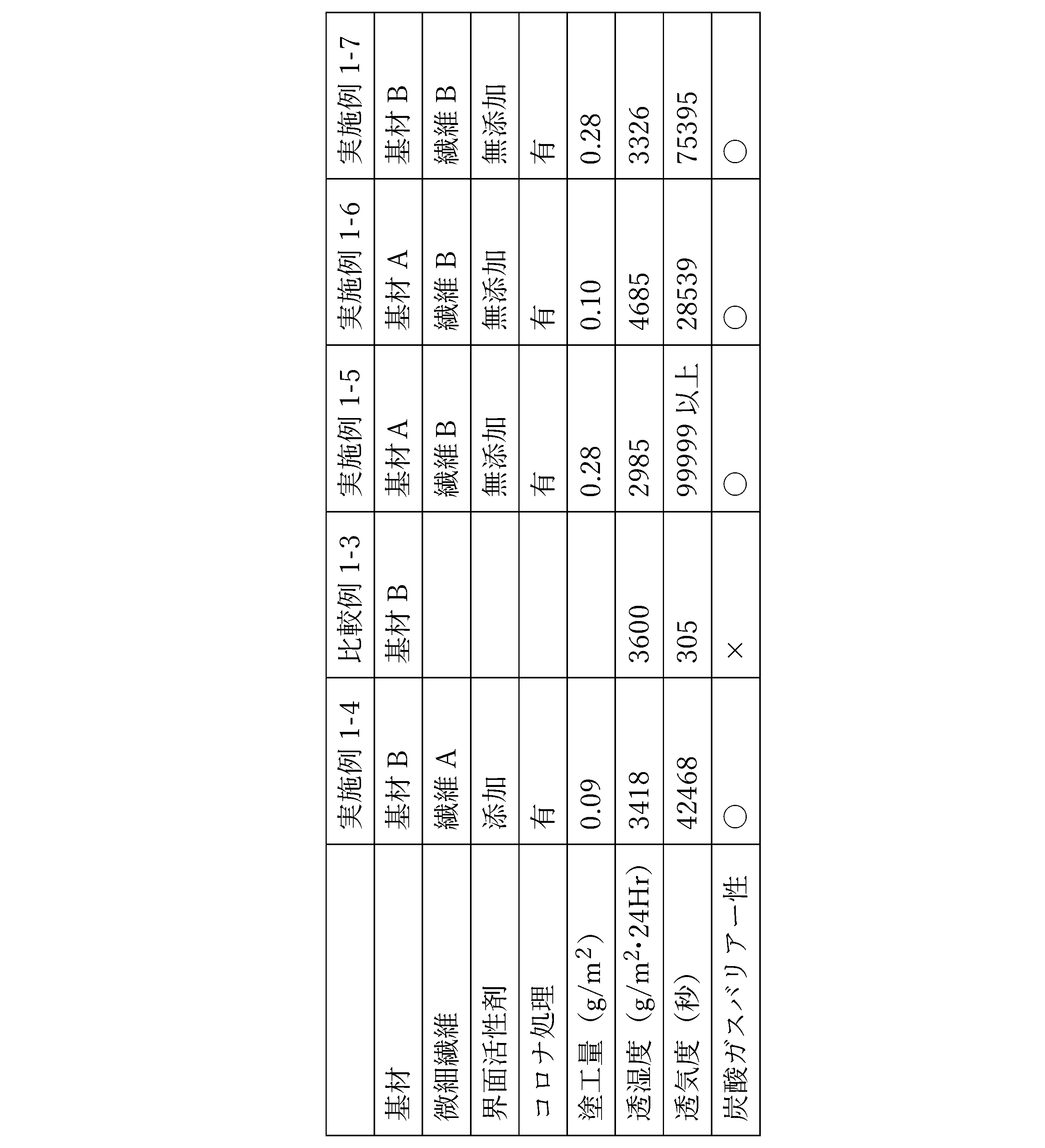
実施例、比較例で得られた全熱交換素子用仕切部材について、透湿度、透気度を測定し、表1、表2に示す。
「透湿度」
20℃、65%RHの条件下で、JIS Z0208:1976に準拠して測定した。但し、下記式により算出した。
透湿度=(a+b)/2
ここで、a=測定開始1時間後の質量増分
b=測定開始1時間後から測定開始2時間後の1時間の質量増分
実施例、比較例で得られた全熱交換素子用仕切部材について、透湿度、透気度を測定し、表1、表2に示す。
「透湿度」
20℃、65%RHの条件下で、JIS Z0208:1976に準拠して測定した。但し、下記式により算出した。
透湿度=(a+b)/2
ここで、a=測定開始1時間後の質量増分
b=測定開始1時間後から測定開始2時間後の1時間の質量増分
「透気度」
JAPAN.TAPPI 紙パルプ試験方法 No.5-2:2000の王研式透気度法に準拠して測定した。
JAPAN.TAPPI 紙パルプ試験方法 No.5-2:2000の王研式透気度法に準拠して測定した。
「二酸化炭素ガスバリアー性」
12cm角の仕切部材を用意し、高濃度のCO2を供試し、CO2濃度を測定する容器Aと、常に外気を通気させる容器Bと、容器Aおよび容器Bの間に用意した仕切部材を配置させた測定装置を用いた。常温・常圧条件下で、容器AにCO2を20000ppm封入した後、15分間放置し、その後容器A内のCO2濃度をCO2分析計を用いて測定した。仕切部材を介して15分間に通過したCO2の透過量は、容器A内のCO2濃度低下として求められる。容器A内のCO2濃度が2500ppm以上のとき、仕切部材の炭酸ガスバリアー性は良好であると判定し〇を、2500ppm未満のときは不良として×の判断とした。
評価結果を下記表1および表2に示す。
12cm角の仕切部材を用意し、高濃度のCO2を供試し、CO2濃度を測定する容器Aと、常に外気を通気させる容器Bと、容器Aおよび容器Bの間に用意した仕切部材を配置させた測定装置を用いた。常温・常圧条件下で、容器AにCO2を20000ppm封入した後、15分間放置し、その後容器A内のCO2濃度をCO2分析計を用いて測定した。仕切部材を介して15分間に通過したCO2の透過量は、容器A内のCO2濃度低下として求められる。容器A内のCO2濃度が2500ppm以上のとき、仕切部材の炭酸ガスバリアー性は良好であると判定し〇を、2500ppm未満のときは不良として×の判断とした。
評価結果を下記表1および表2に示す。

(実施例2-1)
<全熱交換素子用仕切部材の製造>
上記で得られた微細セルロース繊維Aの0.4%水分散液99.2部に、ポリエーテル系の界面活性剤(商品名:SN ウェット 985、サンノプコ社製、76%水分散液)を0.8部添加して塗工液とした。
上記基材Aの一方の面に、塗工液をメイヤーバーで、乾燥後の微細セルロース繊維Aの付着量が0.12g/m2となるように手塗り塗工、乾燥して、全熱交換素子用仕切部材を得た。なお、仕切部材の面密度は10.29g/m2であった。
<全熱交換素子用仕切部材の製造>
上記で得られた微細セルロース繊維Aの0.4%水分散液99.2部に、ポリエーテル系の界面活性剤(商品名:SN ウェット 985、サンノプコ社製、76%水分散液)を0.8部添加して塗工液とした。
上記基材Aの一方の面に、塗工液をメイヤーバーで、乾燥後の微細セルロース繊維Aの付着量が0.12g/m2となるように手塗り塗工、乾燥して、全熱交換素子用仕切部材を得た。なお、仕切部材の面密度は10.29g/m2であった。
(実施例2-2)
実施例2-1において、基材を基材Bに変更した。更に、乾燥後の微細セルロース繊維Aの付着量が0.25g/m2となるように手塗り塗工、乾燥した以外は実施例2-1と同様にして、全熱交換素子用仕切部材を得た。なお、仕切部材の面密度は9.89g/m2であった。
実施例2-1において、基材を基材Bに変更した。更に、乾燥後の微細セルロース繊維Aの付着量が0.25g/m2となるように手塗り塗工、乾燥した以外は実施例2-1と同様にして、全熱交換素子用仕切部材を得た。なお、仕切部材の面密度は9.89g/m2であった。
(実施例2-3)
実施例2-1において、以下のとおり行った以外は実施例2-1と同様にして、全熱交換素子用仕切部材を得た。
実施例2-1において、以下のとおり行った以外は実施例2-1と同様にして、全熱交換素子用仕切部材を得た。
<全熱交換素子用仕切部材の製造>
上記で得られた微細セルロース繊維Bの0.4%分散液を塗工液とした。
上記基材Aの一方の面に、コロナ放電処理を施したのち、塗工液をメイヤーバーで、乾燥後の微細セルロース繊維Bの付着量が0.35g/m2となるように手塗り塗工、乾燥して、全熱交換素子用仕切部材を得た。なお、仕切部材の面密度は10.35g/m2であった。
上記で得られた微細セルロース繊維Bの0.4%分散液を塗工液とした。
上記基材Aの一方の面に、コロナ放電処理を施したのち、塗工液をメイヤーバーで、乾燥後の微細セルロース繊維Bの付着量が0.35g/m2となるように手塗り塗工、乾燥して、全熱交換素子用仕切部材を得た。なお、仕切部材の面密度は10.35g/m2であった。
(比較例2-1)
実施例2-1の全熱交換素子用仕切部材の製造において、乾燥後の微細セルロース繊維Aの付着量が0.02g/m2となるように塗工、乾燥した以外は実施例2-1と同様にして、全熱交換素子用仕切部材を得た。なお、仕切部材の面密度は10.05g/m2であった。
実施例2-1の全熱交換素子用仕切部材の製造において、乾燥後の微細セルロース繊維Aの付着量が0.02g/m2となるように塗工、乾燥した以外は実施例2-1と同様にして、全熱交換素子用仕切部材を得た。なお、仕切部材の面密度は10.05g/m2であった。
(比較例2-2)
全熱交換素子用仕切部材として基材Aをそのまま使用した。
全熱交換素子用仕切部材として基材Aをそのまま使用した。
(比較例2-3)
全熱交換素子用仕切部材として基材Bをそのまま使用した。
全熱交換素子用仕切部材として基材Bをそのまま使用した。
(実施例2-4)
実施例2-1において、以下のとおり行った以外は実施例2-1と同様にして、全熱交換素子用仕切部材を得た。
<全熱交換素子用仕切部材の製造>
上記で得られた微細セルロース繊維Aの0.5%水分散液を塗工液とした。
上記基材Aの一方の面に、塗工液をバーコーターで塗工し、ドライヤー温度が70℃以上にならないように乾燥して、全熱交換素子用仕切部材を得た。微細セルロース繊維Aの付着量は0.05g/m2であった。なお、仕切部材の面密度は10.05g/m2であった。
実施例2-1において、以下のとおり行った以外は実施例2-1と同様にして、全熱交換素子用仕切部材を得た。
<全熱交換素子用仕切部材の製造>
上記で得られた微細セルロース繊維Aの0.5%水分散液を塗工液とした。
上記基材Aの一方の面に、塗工液をバーコーターで塗工し、ドライヤー温度が70℃以上にならないように乾燥して、全熱交換素子用仕切部材を得た。微細セルロース繊維Aの付着量は0.05g/m2であった。なお、仕切部材の面密度は10.05g/m2であった。
(実施例2-5)
実施例2-1において、以下のとおり行った以外は実施例2-1と同様にして、全熱交換素子用仕切部材を得た。
<全熱交換素子用仕切部材の製造>
上記で得られた微細セルロース繊維Aの0.5%水分散液99.6部に、ポリエーテル系の界面活性剤(商品名:SN ウェット 985、サンノプコ社製、76%水分散液)を0.4部添加して塗工液とした。
上記基材Aの一方の面に、塗工液をバーコーターで塗工し、ドライヤー温度が70℃以上にならないように乾燥して、全熱交換素子用仕切部材を得た。微細セルロース繊維Aの付着量は0.15g/m2であった。なお、仕切部材の面密度は10.24g/m2であった。
実施例2-1において、以下のとおり行った以外は実施例2-1と同様にして、全熱交換素子用仕切部材を得た。
<全熱交換素子用仕切部材の製造>
上記で得られた微細セルロース繊維Aの0.5%水分散液99.6部に、ポリエーテル系の界面活性剤(商品名:SN ウェット 985、サンノプコ社製、76%水分散液)を0.4部添加して塗工液とした。
上記基材Aの一方の面に、塗工液をバーコーターで塗工し、ドライヤー温度が70℃以上にならないように乾燥して、全熱交換素子用仕切部材を得た。微細セルロース繊維Aの付着量は0.15g/m2であった。なお、仕切部材の面密度は10.24g/m2であった。
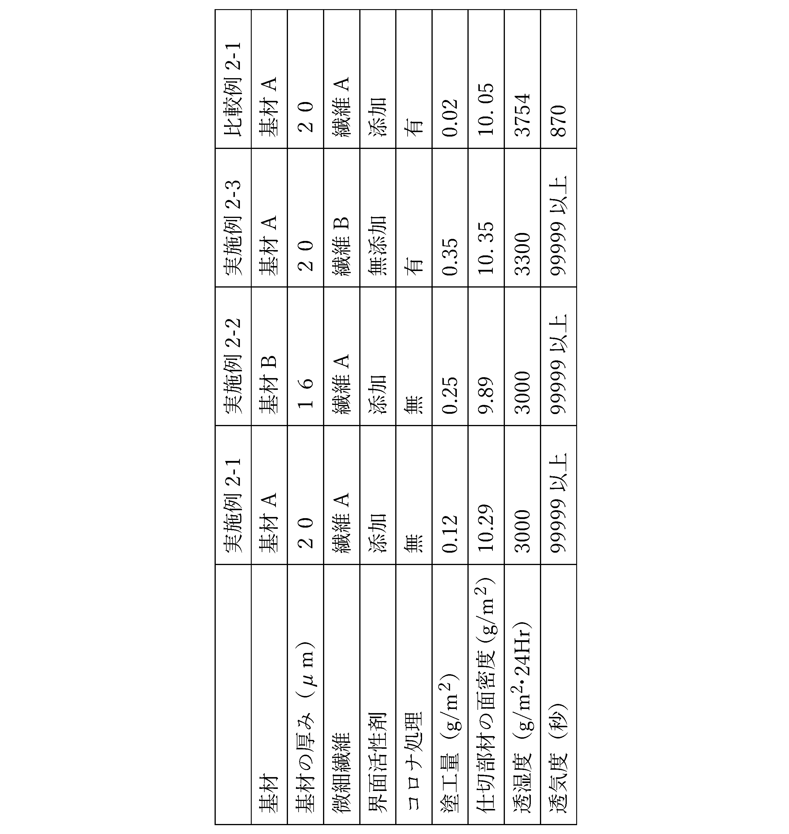
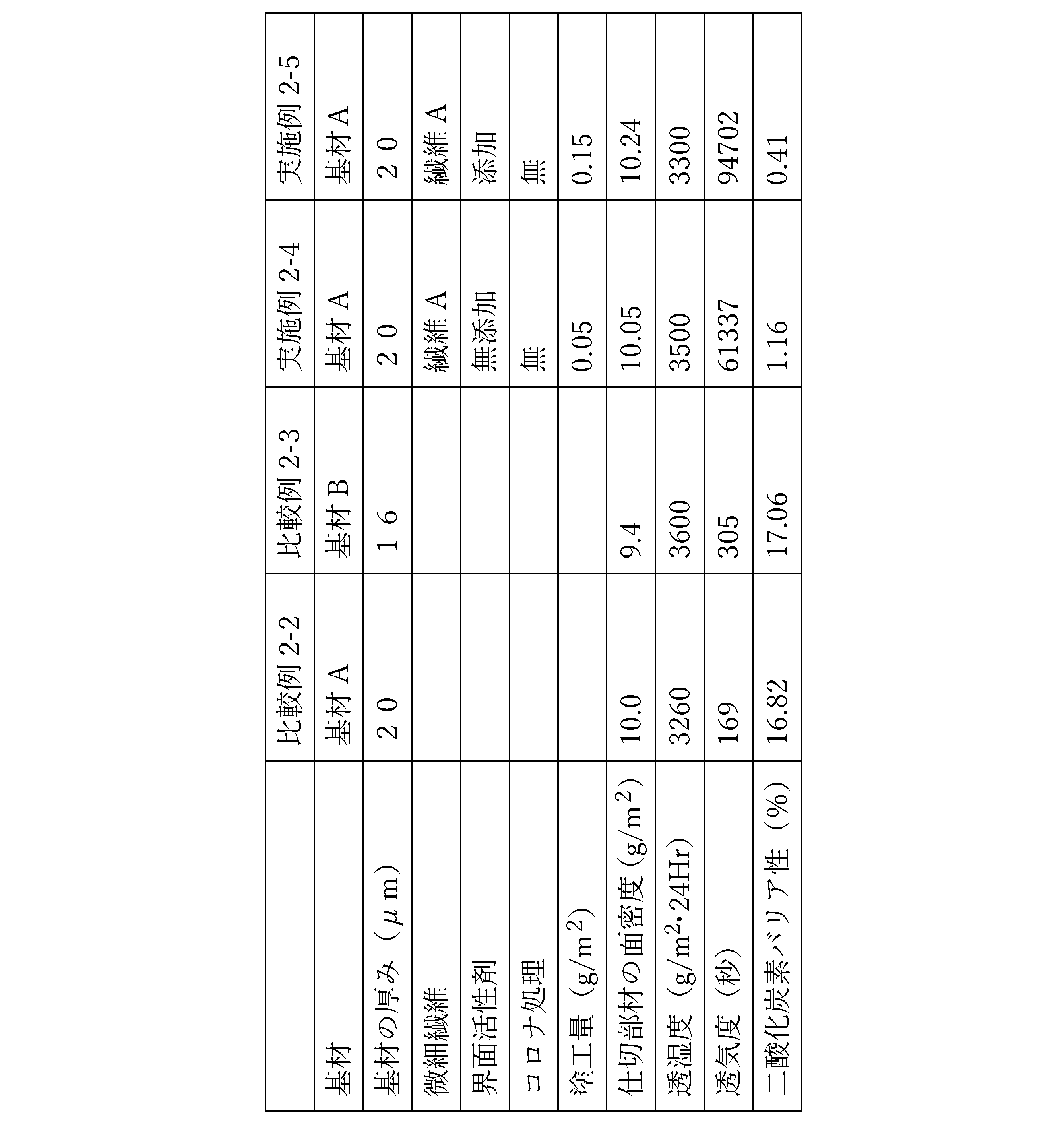
(評価)
実施例、比較例で得られた全熱交換素子用仕切部材について、透湿度、透気度を測定し、表3、表4に示す。また、実施例2-4,2-5、比較例2-2,2-3に関しては、二酸化炭素バリアー性についても評価した。
「透湿度」
20℃×65%RHの条件下で、JIS Z0208:1976に準拠して測定した。但し、下記式により算出した。
透湿度=(a+b)/2
ここで、a=測定開始1時間後の質量増分
b=測定開始1時間後から測定開始2時間後の1時間の質量増分
実施例、比較例で得られた全熱交換素子用仕切部材について、透湿度、透気度を測定し、表3、表4に示す。また、実施例2-4,2-5、比較例2-2,2-3に関しては、二酸化炭素バリアー性についても評価した。
「透湿度」
20℃×65%RHの条件下で、JIS Z0208:1976に準拠して測定した。但し、下記式により算出した。
透湿度=(a+b)/2
ここで、a=測定開始1時間後の質量増分
b=測定開始1時間後から測定開始2時間後の1時間の質量増分
「透気度」
JAPAN.TAPPI 紙パルプ試験方法 No.5-2:2000の王研式透気度法に準拠して測定した。
JAPAN.TAPPI 紙パルプ試験方法 No.5-2:2000の王研式透気度法に準拠して測定した。
<二酸化炭素バリアー性>
側面4面と上面1面の各中央に各辺20cmの正方形の窓部を有するアクリル製の各辺1mの立方体形の容器の内部に二酸化炭素(CO2)分析計を設置したものを測定装置とした。
前記測定装置の各窓部に、25cm角とした仕切部材を貼った状態で、容器内に二酸化炭素を5,000ppm封入し、20℃×65%条件下でCO2の濃度を15分おきに4回、計1時間測定した。
15分後、30分後、45分後、60分後の各測定値より、各時点の二酸化炭素濃度の低下率を求め、更に平均を求めて、測定した試料の二酸化炭素濃度低下率とする。二酸化炭素濃度低下率が低い程、仕切部材は、二酸化炭素(CO2)バリアー性に優れている。
なお、二酸化炭素濃度低下率が1.3%以下のものが仕切部材として好適に用いられる。
側面4面と上面1面の各中央に各辺20cmの正方形の窓部を有するアクリル製の各辺1mの立方体形の容器の内部に二酸化炭素(CO2)分析計を設置したものを測定装置とした。
前記測定装置の各窓部に、25cm角とした仕切部材を貼った状態で、容器内に二酸化炭素を5,000ppm封入し、20℃×65%条件下でCO2の濃度を15分おきに4回、計1時間測定した。
15分後、30分後、45分後、60分後の各測定値より、各時点の二酸化炭素濃度の低下率を求め、更に平均を求めて、測定した試料の二酸化炭素濃度低下率とする。二酸化炭素濃度低下率が低い程、仕切部材は、二酸化炭素(CO2)バリアー性に優れている。
なお、二酸化炭素濃度低下率が1.3%以下のものが仕切部材として好適に用いられる。
1 仕切部材
2 間隔部材
4 第1の空気流路
5 第2の空気流路
10 全熱交換素子
2 間隔部材
4 第1の空気流路
5 第2の空気流路
10 全熱交換素子
Claims (15)
- 疎水性多孔質基材と、親水性材料とを含む全熱交換素子用仕切部材であって、
透気度が10000秒以上であり、20℃、65%RHの条件下での透湿度が2500g/m2・24Hr以上である全熱交換素子用仕切部材。 - 疎水性多孔質基材と、
前記疎水性多孔質基材の少なくとも孔部分に、繊維幅1~1000nmの高分子多糖類の微細繊維とを含有し、
透気度が10000秒以上であり、20℃、65%RHの条件下での透湿度が2500g/m2・24Hr以上である全熱交換素子用仕切部材。 - 前記微細繊維が微細セルロース繊維である請求項2記載の全熱交換素子用仕切部材。
- 前記疎水性多孔質基材の透気度が1000秒以下である請求項2記載の全熱交換素子用仕切部材。
- 前記疎水性多孔質基材の厚みが5μm以上30μm以下である請求項4記載の全熱交換素子用仕切部材。
- 前記疎水性多孔質基材に、前記微細繊維が付着している請求項1記載の全熱交換素子用仕切部材。
- 疎水性多孔質基材と、親水性材料とを含む全熱交換素子用仕切部材であって、
前記親水性材料が、前記疎水性多孔質基材に付着しており、
前記疎水性多孔質基材の厚みが5μm以上30μm以下であり、
前記親水性材料の付着量が0.01g/m2以上8g/m2以下であり、
全熱交換素子用仕切部材としての面密度が30g/m2以下、透気度が10000秒以上である全熱交換素子用仕切部材。 - 請求項1~7のいずれか一つに記載の全熱交換素子用仕切部材を複数備えると共に、
前記全熱交換素子用仕切部材と、その上に設けられた前記間隔保持部材とが形成する第1空気流路と、前記第1空気流路を形成する前記全熱交換素子用仕切部材と、その下に設けられた前記間隔保持部材とが形成する第2空気流路とを有する全熱交換素子。 - 疎水性多孔質基材に、繊維幅1~1000nmの高分子多糖類の微細繊維を含有する塗工液を塗工、乾燥する全熱交換素子用仕切部材の製造方法。
- 前記塗工液が界面活性剤を含有する請求項9記載の全熱交換素子用仕切部材の製造方法。
- 前記微細繊維の塗工量が0.01g/m2以上8g/m2以下である請求項9記載の全熱交換素子用仕切部材の製造方法。
- 前記微細繊維が微細セルロース繊維である請求項9記載の全熱交換素子用仕切部材の製造方法。
- 前記疎水性多孔質基材の透気度が1000秒以下である請求項9記載の全熱交換素子用仕切部材の製造方法。
- 前記疎水性多孔質基材に表面親水化処理を行った後、前記塗工液を塗工する請求項9記載の全熱交換素子用仕切部材の製造方法。
- 厚みが5μm以上30μm以下である疎水性多孔質基材の少なくとも片面に、親水性材料の付着量が0.01g/m2以上8g/m2以下となるように前記親水性材料を含有する塗工液を塗工、乾燥する、面密度が30g/m2以下、透気度が10000秒以上の全熱交換素子用仕切部材の製造方法。
Priority Applications (1)
| Application Number | Priority Date | Filing Date | Title |
|---|---|---|---|
| CN202480037971.5A CN121263650A (zh) | 2023-07-06 | 2024-07-04 | 全热交换元件用分隔构件、使用了全热交换元件用分隔构件的全热交换元件以及全热交换元件用分隔构件的制造方法 |
Applications Claiming Priority (4)
| Application Number | Priority Date | Filing Date | Title |
|---|---|---|---|
| JP2023111450 | 2023-07-06 | ||
| JP2023-111450 | 2023-07-06 | ||
| JP2023-111449 | 2023-07-06 | ||
| JP2023111449 | 2023-07-06 |
Publications (1)
| Publication Number | Publication Date |
|---|---|
| WO2025009600A1 true WO2025009600A1 (ja) | 2025-01-09 |
Family
ID=94171602
Family Applications (1)
| Application Number | Title | Priority Date | Filing Date |
|---|---|---|---|
| PCT/JP2024/024305 Ceased WO2025009600A1 (ja) | 2023-07-06 | 2024-07-04 | 全熱交換素子用仕切部材、それを用いた全熱交換素子、及び全熱交換素子用仕切部材の製造方法 |
Country Status (2)
| Country | Link |
|---|---|
| CN (1) | CN121263650A (ja) |
| WO (1) | WO2025009600A1 (ja) |
Citations (2)
| Publication number | Priority date | Publication date | Assignee | Title |
|---|---|---|---|---|
| WO2019026823A1 (ja) * | 2017-07-31 | 2019-02-07 | 王子ホールディングス株式会社 | 全熱交換器用シート、全熱交換器用素子、及び全熱交換器 |
| JP2019162818A (ja) * | 2018-03-20 | 2019-09-26 | 旭化成株式会社 | 薄膜セルロース微細繊維積層シート |
-
2024
- 2024-07-04 CN CN202480037971.5A patent/CN121263650A/zh active Pending
- 2024-07-04 WO PCT/JP2024/024305 patent/WO2025009600A1/ja not_active Ceased
Patent Citations (2)
| Publication number | Priority date | Publication date | Assignee | Title |
|---|---|---|---|---|
| WO2019026823A1 (ja) * | 2017-07-31 | 2019-02-07 | 王子ホールディングス株式会社 | 全熱交換器用シート、全熱交換器用素子、及び全熱交換器 |
| JP2019162818A (ja) * | 2018-03-20 | 2019-09-26 | 旭化成株式会社 | 薄膜セルロース微細繊維積層シート |
Also Published As
| Publication number | Publication date |
|---|---|
| CN121263650A (zh) | 2026-01-02 |
Similar Documents
| Publication | Publication Date | Title |
|---|---|---|
| EP2026029B1 (en) | Sheets for total heat exchangers | |
| EP2312051B1 (en) | Total heat exchanging element paper | |
| JP6571894B1 (ja) | 全熱交換素子用紙及び全熱交換素子 | |
| JP2021147727A (ja) | 全熱交換素子用紙及び全熱交換素子 | |
| WO2025009600A1 (ja) | 全熱交換素子用仕切部材、それを用いた全熱交換素子、及び全熱交換素子用仕切部材の製造方法 | |
| JP2025010103A (ja) | 全熱交換素子用仕切部材、それを用いた全熱交換素子、及び全熱交換素子用仕切部材の製造方法 | |
| JP2025010102A (ja) | 全熱交換素子用仕切部材、それを用いた全熱交換素子、及び全熱交換素子用仕切部材の製造方法 | |
| WO2020194461A1 (ja) | 全熱交換素子用仕切板およびこれを用いた全熱交換素子および全熱交換器ならびに全熱交換素子用仕切板の製造方法 | |
| CN113424008A (zh) | 全热交换元件用纸和全热交换元件 | |
| JP3223172U (ja) | 全熱交換素子用紙及び全熱交換素子 | |
| JP2025181743A (ja) | 全熱交換素子用仕切部材、及び全熱交換素子 | |
| JP2025181742A (ja) | 全熱交換素子用仕切部材、全熱交換素子、全熱交換素子用仕切部材の製造方法及び塗工液 | |
| WO2025249431A1 (ja) | 全熱交換素子用仕切部材、全熱交換素子、全熱交換素子用仕切部材の製造方法及び塗工液 | |
| JP2025181741A (ja) | ガスバリアシート、及び全熱交換素子 | |
| JP7786033B2 (ja) | 間隔部材用シート及び全熱交換素子 | |
| JPH0124529B2 (ja) | ||
| JP7665281B2 (ja) | 熱交換器 | |
| JPH0515959B2 (ja) | ||
| JP6783975B1 (ja) | 全熱交換素子 | |
| JP2021152230A (ja) | 全熱交換素子用紙及び全熱交換素子 | |
| JP4933279B2 (ja) | 機能性不織布製造方法、機能性不織布、および、立体マスク | |
| JP2019158274A (ja) | 顕熱型熱交換素子 | |
| JP2022129183A (ja) | 全熱交換素子 | |
| JP2022129184A (ja) | 全熱交換素子 | |
| JP2011110495A (ja) | 除湿用シート状物 |
Legal Events
| Date | Code | Title | Description |
|---|---|---|---|
| 121 | Ep: the epo has been informed by wipo that ep was designated in this application |
Ref document number: 24836112 Country of ref document: EP Kind code of ref document: A1 |
|
| NENP | Non-entry into the national phase |
Ref country code: DE |