WO2025009435A1 - 制御デバイス、方法、及びコンピュータプログラム製品 - Google Patents
制御デバイス、方法、及びコンピュータプログラム製品 Download PDFInfo
- Publication number
- WO2025009435A1 WO2025009435A1 PCT/JP2024/022912 JP2024022912W WO2025009435A1 WO 2025009435 A1 WO2025009435 A1 WO 2025009435A1 JP 2024022912 W JP2024022912 W JP 2024022912W WO 2025009435 A1 WO2025009435 A1 WO 2025009435A1
- Authority
- WO
- WIPO (PCT)
- Prior art keywords
- sensor
- obstacle
- information
- driver
- board
- Prior art date
- Legal status (The legal status is an assumption and is not a legal conclusion. Google has not performed a legal analysis and makes no representation as to the accuracy of the status listed.)
- Ceased
Links
Images














Classifications
-
- G—PHYSICS
- G08—SIGNALLING
- G08G—TRAFFIC CONTROL SYSTEMS
- G08G1/00—Traffic control systems for road vehicles
- G08G1/16—Anti-collision systems
- G08G1/167—Driving aids for lane monitoring, lane changing, e.g. blind spot detection
-
- G—PHYSICS
- G08—SIGNALLING
- G08G—TRAFFIC CONTROL SYSTEMS
- G08G1/00—Traffic control systems for road vehicles
- G08G1/16—Anti-collision systems
- G08G1/161—Decentralised systems, e.g. inter-vehicle communication
- G08G1/162—Decentralised systems, e.g. inter-vehicle communication event-triggered
-
- G—PHYSICS
- G08—SIGNALLING
- G08G—TRAFFIC CONTROL SYSTEMS
- G08G1/00—Traffic control systems for road vehicles
- G08G1/16—Anti-collision systems
- G08G1/161—Decentralised systems, e.g. inter-vehicle communication
- G08G1/163—Decentralised systems, e.g. inter-vehicle communication involving continuous checking
-
- G—PHYSICS
- G08—SIGNALLING
- G08G—TRAFFIC CONTROL SYSTEMS
- G08G1/00—Traffic control systems for road vehicles
- G08G1/16—Anti-collision systems
- G08G1/168—Driving aids for parking, e.g. acoustic or visual feedback on parking space
Definitions
- the subject matter relates to a control device, method, and computer program product for controlling a driver assistance system of a vehicle.
- ADAS advanced driver assistance systems
- V2X vehicle to everything
- Patent document 1 describes a system and apparatus for detecting moving objects that enter the field of view of a vehicle's camera device.
- This system uses a positioning device installed in the vehicle itself and location information periodically received from a mobile terminal owned by the moving object.
- a moving object enters the field of view of the camera, an area for detecting the mobile unit is set in the image captured by the camera based on the location information of the mobile terminal of the mobile unit and the vehicle's own traveling direction, and the mobile unit is detected.
- V2X information e.g., in terms of the specifications and scope of application of the external device
- one of the typical application scenarios of V2X is related to blind spot warning, which means that the blind spot warning alerts the driver when an obstacle is detected in the blind spot area of the on-board sensor(s).
- Patent document 2 describes such blind spot warning to the driver of the own vehicle by using V2X information in addition to the own vehicle sensors.
- the system uses the following logic: if an obstacle is detected by both, i.e., the on-board sensor(s) and V2X, the obstacle is not considered to be an obstacle inside the blind spot (i.e., blind spot area); on the other hand, if an obstacle is detected only by V2X, the obstacle is considered to be an obstacle inside the blind spot area.
- the ego-vehicle when the ego-vehicle is running in a forward direction, it is a very dangerous situation if there is a first obstacle in front of the ego-vehicle at a short distance to the ego-vehicle.
- the first obstacle in front of the ego-vehicle blocks the detection area of the sensor, so then other obstacles located behind the first obstacle, such as a second obstacle, a third obstacle, etc., can be detected only by V2X.
- this situation can occur when a first nearby obstacle blocks the sensor view, thereby creating a huge blind spot, in which further obstacles (farther away) may be located, and the further obstacles can be detected only by V2X due to the blind spot created by the first obstacle.
- the subject matter described in this specification addresses the technical object of improving driving safety of vehicles equipped with driver assistance systems and/or automated driving systems.
- safety is increased in situations where obstacles are detected by V2X and not by on-board sensor(s).
- This object is achieved by the subject matter of the independent claims. Further preferred developments are described by the dependent claims.
- a control device, a method and a computer program product are proposed. Furthermore, an own vehicle equipped with a control device of such a computer program product is also part of the present disclosure.
- the subject matter disclosed herein improves the performance of a driver assistance or automated driving system in the event of detection of an obstacle by V2X rather than by on-board sensor(s) of the own vehicle.
- the driver assistance system controlled by the disclosed subject matter may be, for example, automatic emergency braking (AEB), adaptive cruise control (ACC), or lane change assist (LCA). Other types of driver assistance systems may also be combined with the proposed subject matter.
- the system may also include or have automated driving capabilities.
- the vehicle comprises an on-board sensor obstacle information acquisition unit configured to acquire obstacle information detected by one or more on-board sensors covering a sensor detection area and a blind spot area, which is an area outside the sensor detection area.
- the term sensor detection area is used for the area covered by the field of view of the on-board sensor(s) of the own vehicle, and a blind spot or blind spot area is an area not covered by the on-board sensor(s) of the vehicle.
- an external sensor i.e., V2X information provided to the own vehicle, may cover the blind spot area.
- control device has an on-board sensor sensing functionality status acquisition unit configured to acquire the functionality status (functionality status information) of one or more on-board sensors.
- the functionality status will be described below in relation to various examples.
- the functionality status may cover reliability information of the on-board sensor(s), degradation of the on-board sensor's detection area due to various factors, size, shape, dimensions of the sensor's detection area of the host vehicle, etc.
- control device comprises an external sensor obstacle information acquisition unit configured to acquire obstacle information from one or more external sensors, where obstacle information may in particular mean wirelessly received V2X information from other external sensors, such as sensors mounted on other vehicles, to a roadside sensor unit, etc.
- obstacle information may in particular mean wirelessly received V2X information from other external sensors, such as sensors mounted on other vehicles, to a roadside sensor unit, etc.
- the control device then includes an assistance determination unit configured to determine whether an external sensor detected obstacle is inside the blind spot area.
- the term external sensor detected obstacle refers in particular to an object or obstacle detected only by the external sensor. Additionally or alternatively, the control device may also cover a situation where both the on-board sensor and the external sensor detect an obstacle, but the reliability of the external sensor is higher compared to the on-board sensor.
- the situation where the reliability of the external sensor is higher compared to the on-board sensor may be determined by any unit or instance of the control device, for example, when a failure of the on-board sensor is discovered by self-diagnosis or when bad weather conditions may reduce the reliability of the on-board sensor(s). This may preferably be included in the functionality status information.
- a check is performed as to whether an external sensor-detected obstacle is inside the blind spot area by/against functionality status information, which may include the sense in which the actual shape of the sensor detection area is taken into account, its reliability, etc.
- Such information preferably originates from an input to the assistance decision unit, in particular from a detection functionality status acquisition unit of the on-board sensor.
- the control device is able to provide further useful output to the driver of the vehicle, thereby enhancing safety.
- control device may further include an obstacle identification unit configured to identify an obstacle detected by the sensor, where the identification may include identifying the type of obstacle, the class of obstacle, whether two obstacles detected by different sensors are the same, etc. This may further increase the accuracy of the control device and therefore improve reliability and safety.
- an obstacle identification unit configured to identify an obstacle detected by the sensor, where the identification may include identifying the type of obstacle, the class of obstacle, whether two obstacles detected by different sensors are the same, etc. This may further increase the accuracy of the control device and therefore improve reliability and safety.
- control device a first driver assistance execution unit configured to perform driver assistance based on on-board sensor obstacle information regarding an obstacle detected by an on-board sensor(s), the on-board sensor obstacle information including various data such as type, size, pose, speed, etc.; a second driver assistance execution unit configured to execute driver assistance, preferably for the blind spot area, when the assistance determination unit determines that there is an external sensor-detected obstacle in the blind spot area; and a third driver assistance execution unit configured to execute driver assistance when the assistance determination unit determines that there is an external sensor-detected obstacle within the sensor detection area but not in the blind spot area.
- Driver assistance may also include providing various types of guidance and/or warnings, such as visual guidance displayed on the vehicle, audio guidance, etc.
- the assistance determination unit may be configured to determine whether an external sensor-detected obstacle is in a blind spot area based on the functionality status information, the reliability determined for the on-board(s), and/or the risk. In other words, this determination is preferably made based on an input to the assistance determination unit, which may include various data, as will be explained in relation to the embodiment in the figure description.
- control device may include a driving behavior acquisition unit configured to acquire driving behavior of the host vehicle, including speed data, direction data, and other data, which may be provided by an odometry, satellite navigation system, etc.
- driving behavior acquisition unit is part of the control device
- the first driver assistance execution unit may be configured to execute driver assistance based on on-board sensor obstacle information and driving behavior information.
- driver assistance execution units has the advantage that the information of the assistance decision unit can be put into practice and in particular this information can be used to communicate with the driver, resulting in increased driving safety.
- an on-board sensor sensing functionality status acquisition unit configured to acquire a sensor sensing area of one or more on-board sensors
- the assistance judgment unit is configured to judge whether the external sensor-detected obstacle is in the blind spot area according to the position of the external sensor-detected obstacle and the sensor detection area
- the second driver assistance execution unit is configured to send a blind spot warning to a driver of the host vehicle when an external sensor-detected obstacle exists/is outside the detection area, preferably based on reliability and risk
- a third driver assistance execution unit is configured to send an obstacle caution warning to the driver, preferably based on reliability and risk, when an external sensor-detected obstacle is present/located within the detection area (sensor detection area).
- the input from the on-board sensor detection functionality status acquisition unit to the assistance determination unit is in particular related to the determination of the sensor detection area, i.e. the size, shape, dimensions, position, etc. of the sensor detection area.
- driving safety is increased and the second driver assistance execution unit can issue a blind spot warning, in particular when an external sensor-detected obstacle is detected outside the determined sensor detection area.
- the sensor detection area may change from time to time due to the movement of the vehicle, changes in the surroundings of the vehicle, etc., the sensor detection area is refreshed for each new information or at a certain period.
- the third driver assistance execution unit can issue an obstacle caution warning to the driver when an external sensor-detected obstacle is inside the sensor detection area. In other words, various scenarios are covered to provide the driver with more detailed information.
- the third driver assistance execution unit may be configured to additionally send a sensor failure warning if an external sensor detected obstacle is detected inside the detection area more times than a threshold value.
- the threshold value may be preset.
- the threshold value may be replaced by a sensor failure counter or by a certain period of time during which two or more "sensor failures" occur, where a sensor failure includes meaning that the on-board sensor(s) failed to detect an obstacle inside the sensor detection area of the on-board sensor and this obstacle was detected only by an external sensor. This increases the reliability and therefore the safety of the control device.
- the on-board sensor sensing functionality status acquisition unit is configured to determine the sensor sensing area from the mounting position, sensing range, and/or sensing angle of the on-board sensor(s).
- a surrounding map information acquisition unit is provided, configured to acquire information of the position(s) and shape of surrounding buildings from the map information
- the on-board sensor sensing functionality status acquisition unit is additionally configured to calculate the sensor detection area using the building information.
- the building information may also cover other information other than information about buildings, such as any static (or dynamic) objects around the host vehicle, such as trees, walls, natural structures, etc. With this further information, it is possible to more accurately determine the sensor detection area, since for example buildings may block the sensor detection area of the host vehicle, thereby limiting/reducing the sensor detection area of the host vehicle.
- the on-board sensor sensing functionality status acquisition unit is configured to acquire (self-)diagnostic information of the on-board sensor(s), which may be provided by the on-board sensor(s), or from a respective unit performing diagnostics, or from an obstacle detection software program, etc.;
- the assistance judgment unit is configured to judge whether an external sensor-detected obstacle is in a blind spot area based on the self-diagnosis information;
- the second driver assistance execution unit is configured to send a blind spot warning to the driver when there is an external sensor-detected obstacle and the self-diagnosis information indicates a normal status, preferably based on reliability and risk;
- the third driver assistance execution unit is configured to send an obstacle caution warning and a sensor fault warning to the driver, preferably based on reliability and risk, when an external sensor-detected obstacle is present and the self-diagnosis information indicates an abnormal status.
- This modification can cover situations where the sensor detection area is reduced due to on-board sensor failure, etc., and can be used to adapt the behavior of the driver assistance execution unit.
- the on-board sensor sensing functionality status acquisition unit is configured to acquire self-diagnosis information including one or more invalid sensor sensing areas;
- the assistance judgment unit is configured to judge whether the external sensor-detected obstacle is in a blind spot area based on the position of the detected obstacle and the one or more invalid detection areas;
- the second driver assistance execution unit is configured to send a blind spot warning to the driver when an external sensor detected obstacle is present outside the invalid sensor detection area, preferably based on reliability and risk;
- the third driver assistance execution unit is configured to send sensor failure and obstacle caution warnings to the driver, preferably based on reliability and risk, when an external sensor detected obstacle is present within one or more of the invalid sensor detection areas automatically extracted by known mud or raindrop detection algorithms known in the art and not further described herein.
- This modification can cover situations where the sensor detection area is reduced due to on-board sensor failure, etc., and can be used to adapt the behavior of the driver assistance execution unit.
- the on-board sensor sensing functionality status acquisition unit is configured to acquire ambient environment information;
- the assistance judgment unit is configured to judge whether an external sensor-detected obstacle is in a blind spot area based on a sensor specification (which may include an on-board sensor type, a field of view, an on-board pose, etc.) and environmental information;
- the second driver assistance execution unit is configured to send a blind spot warning to the driver when an external sensor detected obstacle is present and the environment is not classified as a severe condition (for the on-board sensor), preferably based on reliability and risk (meaning that a warning can be issued only if the reliability of the detection result is sufficiently confirmed in a known manner and/or the situation is identified as having a predetermined or higher risk, which can also be determined based on a known procedure);
- the third driver assistance execution unit is configured to send an obstacle caution warning and a harsh environment warning to the driver, preferably based on reliability and risk, when an external sensor detected obstacle is present and the environment is classified as harsh conditions (for the on-board sensors).
- Classification of harsh conditions into various categories can be performed in real time, for example based on a predefined method, table, etc.
- This modification can cover situations where the sensor detection area is reduced or the detection of the on-board sensor(s) is less reliable due to external conditions such as heavy rain, snow, dark areas, etc., and can be used to adapt the behavior of the driver assistance execution unit.
- the on-board sensor sensing functionality status acquisition unit is configured to acquire weather information as the ambient environment information.
- the on-board sensor detection functionality status acquisition unit is configured to acquire time information as the ambient environment information.
- the on-board sensor sensing functionality status acquisition unit is configured to acquire intermediate sensing information, e.g., from an obstacle detection program/algorithm;
- the assistance judgment unit is configured to judge whether an external sensor-detected obstacle is in a blind spot area according to the position and the position of the intermediate detection information;
- the second driver assistance execution unit is configured to send a blind spot warning to the driver when the intermediate detection information is not present in proximity to an external sensor detected obstacle, preferably based on reliability and risk;
- the third driver assistance execution unit is configured to send an obstacle caution warning to the driver when the intermediate detection information is in proximity to an external sensor detected obstacle, preferably based on reliability and risk.
- Such a variant uses intermediate (detection) information resulting from possible intermediate steps in the object detection procedure (as known in the art) and which may be raw data or semi-processed raw data regarding the detected object.
- intermediate (detection) information resulting from possible intermediate steps in the object detection procedure (as known in the art) and which may be raw data or semi-processed raw data regarding the detected object.
- it covers cases where possible detected artifacts may be included in the assistance decision process, which may increase the time between detection and warning output, so that the driver may be warned early (even if the detection on which the warning is based may later be considered a false positive).
- the on-board sensor detection functionality status acquisition unit is configured to acquire the position of an on-board sensor obstacle being detected by the on-board sensor(s) and preferably evaluate the risk posed thereby;
- the assistance judgment unit is configured to judge whether the external sensor-detected obstacle is in a blind spot area based on the distance to the detected on-board sensor obstacle;
- the second driver assistance execution unit is configured to send a blind spot warning to the driver, preferably based on reliability and risk, if the closest on-board sensor obstacle is not close, preferably checked by a predetermined threshold distance;
- the third driver assistance execution unit is configured to send a soft warning to the driver, preferably based on reliability and risk, when the distance of the closest on-board sensor obstacle is close, for example less than a predetermined distance.
- This variant can in particular deal with situations where two obstacles are detected, one by the on-board sensor and another one only by the external sensor, for example also due to the fact that the sensor detection area can be reduced due to the presence of a first detected obstacle.
- the control device may not provide a strong warning about the second detected obstacle in the blind spot area, since this may distract the driver from his attempts to deal with the first (very close) detected obstacle.
- a surrounding map acquisition unit configured to acquire road structure information around the vehicle
- the assistance judgment unit is configured to determine that an external sensor-detected obstacle is within a blind spot area when the vehicle is in an intersection.
- the second driving aid is a warning system configured to indicate to the driver the type and direction of an obstacle.
- the second driving assistance and the third driving assistance are configured to use object tracking time information for warning judgment.
- the external sensor obstacle information acquisition unit is configured to acquire identity information including a license plate, blinker on condition, brake on condition, vehicle overall length, vehicle width, and/or vehicle color
- the obstacle identification unit is configured to use the identity information to identify whether the external sensor detected obstacle and the on-board sensor obstacle are the same obstacle, thereby reducing false detection.
- one aspect may relate to a method of controlling a driver assistance system of a vehicle, preferably including the above-mentioned steps performed by a control device.
- one aspect may relate to a computer program product storable in a memory that includes instructions that, when executed by a computer, cause the computer to perform the method(s) described above.
- the present disclosure and claimed subject matter provides additional benefits to vehicle driver safety by improving ADAS/AD-related control.
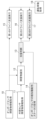
- FIG. 1 shows a schematic representation of a unit of a control device according to the disclosed subject matter.
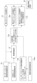
- FIG. 2 illustrates generally an example of a control device in accordance with the disclosed subject matter.
- FIG. 3 shows a schematic representation of a unit of a first embodiment of a control device according to the disclosed subject matter.
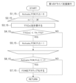
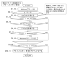
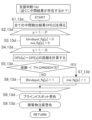
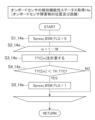
- FIG. 4 shows a flow chart of the steps performed by the first driver execution unit.
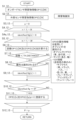
- FIG. 5 shows a flow chart of the steps performed for obstacle identification.
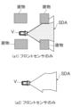
- FIG. 6a illustrates a schematic of an exemplary sensor detection area.
- FIG. 6b illustrates a schematic of an exemplary sensor detection area.
- FIG. 6c illustrates a schematic of an exemplary sensor detection area.
- FIG. 7a illustrates diagrammatically an example of additionally using surrounding map information to determine the sensor detection area.
- FIG. 7b illustrates diagrammatically an example of additionally using surrounding map information to determine the sensor detection area.
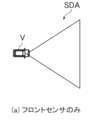
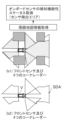
- FIG. 8a illustrates diagrammatically an exemplary front-sensor-only scenario for determining sensor detection area between buildings and the like.
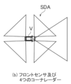
- FIG. 8b illustrates diagrammatically an exemplary front and corner radar sensor scenario for determining the sensor detection area between buildings and the like.
- FIG. 8c illustrates generally an exemplary front sensor and spinning lidar radar sensor scenario for determining the sensor detection area between buildings, etc.
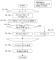
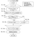
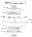
- FIG. 9 shows a flow chart of the steps for determining whether an obstacle detected by an external sensor is inside or outside the sensor detection area.
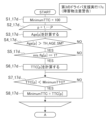
- FIG. 10a shows a flow chart of the steps for determining whether to output a blind spot warning.
- FIG. 10b illustrates an example scenario related to the flowchart of FIG. 10a.
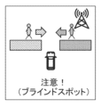
- FIG. 10c illustrates a schematic example of a blind spot warning in relation to the flow chart of FIG. 10a.
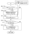
- FIG. 11a shows a part of a flow chart of the steps for determining whether to output an obstacle caution warning and/or a sensor fault warning.
- FIG. 11b shows another part of a flow chart of the steps for determining whether to output an obstacle caution warning and/or a sensor fault warning.
- FIG. 11c illustrates, in a simplified manner, an example of a warning associated with the flow charts of FIGS. 11a and 11b.
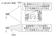
- FIG. 12a shows diagrammatically the sensor detection area defined by the field of view of the on-board sensor and occluding buildings etc.
- FIG. 12a shows diagrammatically the sensor detection area defined by the field of view of the on-board sensor and occluding buildings etc.
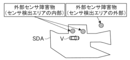
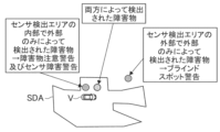
- FIG. 12b illustrates a use case scenario and related technical benefits of the present disclosure in relation to a specific example of a sensor detection area according to FIG. 12a.
- FIG. 12c illustrates a use case scenario and related technical benefits of the present disclosure in relation to a specific example of a sensor detection area according to FIG. 12a.
- FIG. 12d illustrates a use case scenario and related technical benefits of the present disclosure in relation to a specific example of a sensor detection area according to FIG. 12a.
- FIG. 13 illustrates a schematic diagram of a unit of a second embodiment of a control device according to the disclosed subject matter.
- FIG. 14a illustrates diagrammatically a scenario in which the on-board sensors have completely failed.
- FIG. 14b illustrates diagrammatically a scenario in which an on-board sensor has partially failed.
- FIG. 15a shows the steps of a flow chart for processing assistance decisions in case of a full area failure of one or more on-board sensors.
- FIG. 15b shows the steps of a flow chart for processing assistance decisions in case of partial failure of one or more on-board sensors.
- FIG. 16a shows a part of a flow chart of the steps for determining whether to output an obstacle caution warning and/or a sensor fault warning.
- FIG. 16b shows another part of a flow chart of the steps for determining whether to output an obstacle caution warning and/or a sensor fault warning.
- FIG. 16c illustrates, in a simplified manner, an example of a warning associated with the flow charts of FIGS. 16a and 16b.
- FIG. 17 illustrates a schematic diagram of a unit of a third embodiment of a control device according to the disclosed subject matter.
- FIG. 18a shows a schematic of the area of the sensor detection area affected by different environmental conditions.
- FIG. 18b shows a flow chart of the steps of assistance decisions related to environmental conditions as illustrated by FIG. 18a.
- FIG. 19a shows a part of a flow chart of the steps for determining whether to output an obstacle caution warning and/or a sensor fault warning.
- FIG. 19b shows another part of a flow chart of the steps for determining whether to output an obstacle caution warning and/or a sensor fault warning.
- FIG. 19c illustrates, in a simplified manner, an example of a warning associated with the flow charts of FIGS. 19a and 19b.
- FIG. 19a shows a schematic of the area of the sensor detection area affected by different environmental conditions.
- FIG. 18b shows a flow chart of the steps of assistance decisions related to environmental conditions as illustrated by FIG. 18a.
- FIG. 19a shows a
- FIG. 20 illustrates a schematic diagram of a fourth embodiment of a control device according to the disclosed subject matter.
- FIG. 21a illustrates the use of intermediate detection information in a schematic manner.
- FIG. 21b shows a flow chart of the steps of assisted decision making involving the use of intermediate detection information.
- FIG. 22a shows a part of a flow chart of the steps for determining whether to output an obstacle caution warning and/or a sensor fault warning.
- FIG. 22b shows another part of a flow chart of the steps for determining whether to output an obstacle caution warning and/or a sensor fault warning.
- FIG. 22c illustrates, in a simplified manner, an example of a warning associated with the flow charts of FIGS. 22a and 22b.
- FIG. 21a illustrates the use of intermediate detection information in a schematic manner.
- FIG. 21b shows a flow chart of the steps of assisted decision making involving the use of intermediate detection information.
- FIG. 22a shows a part of a flow chart of the steps for determining whether to output an
- FIG. 23 illustrates a schematic diagram of a unit of a fifth embodiment of a control device according to the disclosed subject matter.
- FIG. 24a shows a flow chart of steps associated with a fifth embodiment of the disclosed subject matter.
- FIG. 24b shows a flow chart of steps associated with a fifth embodiment of the disclosed subject matter for providing weak blind spot warning, or blind spot warning.
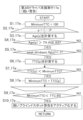
- FIG. 25a shows a flow chart of the steps associated with a fifth embodiment of the disclosed subject matter for generating weak blind spot warning.
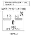
- FIG. 25b illustrates an exemplary blind spot warning schematic.
- FIG. 25c illustrates an exemplary weak blind spot warning schematic.
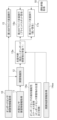
- control device 1 illustrates a control device 1 of the present disclosure, including some of the units of the control device 1 described in more detail below.
- the control device 1 may be mounted on a vehicle V (not shown in FIG. 1, which may instead be identified below as an ego-vehicle).
- vehicle V includes one or more on-board sensors (or simply sensors) that detect one or more obstacles in the vicinity of the vehicle V.
- the on-board sensor(s) may include, for example, radar sensors, camera sensors, lidar sensors, sonar sensors, and/or any other sensor suitable for detecting obstacles in the vicinity of the vehicle V.
- control device 1 is communicatively connected to one or more external sensor(s) (not shown) that may be connected to the control device 1 via vehicle-to-location (V2X) communication.
- the external sensor(s) may also be radar sensors, camera sensors, lidar sensors, sonar sensors, GNSS sensors, and/or any other sensor suitable for detecting obstacles in the surroundings of the vehicle V, and the external sensor(s) may be included, for example, in another vehicle (other than the own vehicle), in a roadside unit, and/or in a mobile device.
- the communication between the on-board sensor(s) and the control device 1 may be performed in real time, while the communication between the external sensor(s) and the control device 1 may be performed, for example, via a cellular network.
- the on-board sensor(s) and the external sensor(s) may both detect obstacles in the area surrounding the vehicle V and may determine multiple obstacle parameters including, for example, obstacle type, position, orientation, speed, yaw rate, and acceleration of the detected obstacles.
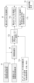
- FIG. 1 shows in particular some of the units of a control device 1 according to the present disclosure, the units being indicated by rectangular boxes containing the name/technical function of the unit.
- the units depicted in FIG. 1 include units that are common to the following embodiments or possible variations of the embodiments not explicitly described, while variations of unit-specific technical functions are possible.
- the units and the entire control device 1 may be constructed by software, hardware, or a combination thereof.
- the unit of FIG. 1 includes an on-board sensor obstacle information acquisition unit 10 that receives (or acquires) data from one or more on-board sensors of the host vehicle V via a communication line (not shown) between the unit and the sensor(s) as is known, which may be a wired line and/or a wireless line.
- a communication line (not shown) between the unit and the sensor(s) as is known, which may be a wired line and/or a wireless line.
- an external sensor obstacle information acquisition unit 11 which receives (or acquires) data from one or more external sensors via a communication line (not shown) between said unit and the external sensor(s) as is known, the communication line being wireless.
- Identification may include a determination that the object (obstacle) detected by the on-board sensor is the same as the object detected by the external sensor, which determination may also be made by comparison of certain characteristics of the detected object, including for example the position of the detected object. Identification may also include identifying which type of obstacle has been detected, for example by a trained Machine Learning or Artificial Intelligence (ML/AI) sub-unit, trained for example to identify humans, other vehicles, traffic signs, etc. For such technical functions, the ML/AI sub-unit is pre-trained by training data including images of each possible detected object/obstacle.
- ML/AI Machine Learning or Artificial Intelligence
- the assistance judgment unit 13 can perform a judgment or discrimination action as described in relation to the specific embodiment below, and based on this result, select or activate further actions by the control device 1 or a unit of the control device 1.
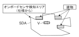
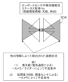
- the assistance judgment includes determining whether an "external sensor-detected obstacle" is within the sensor detection area SDA, which specifies the area/field of view covered by one or more on-board sensors of the host vehicle V.
- An external sensor-detected obstacle is preferably understood as an obstacle/object detected only by the external sensor (and acquired by the respective unit).
- an external sensor-detected obstacle may also be detected by the external sensor(s) and the on-board sensor(s), but in that case the term is only used if the on-board sensor(s) have low reliability or lower reliability compared to the external sensor(s).
- the assistance judgment unit 13 further receives information for making judgment decisions/determinations from the on-board sensor detection functionality status acquisition unit 14.
- modifications of the on-board sensor detection functionality status acquisition unit 14 and the information transmitted to the assistance judgment unit 13 are described in detail. It is possible to combine the various modifications, i.e. to use a combination of the various information of the following various examples.
- FIG. 2 shows further units of the control device 1, which are given the names of their technical configurations/functions as in FIG. 1.
- FIG. 2 shows the assistance decision unit downstream functions/units of the control device 1, which in particular preferably include three driver assistance execution units 15-17, which may be separate units or a combined unit having at least three different driver assistance execution functions.
- the driver assistance execution units receive information from a further unit, which is the driving behavior unit 18.
- driver assistance execution unit 15 that executes standard/normal/known driving assistance as known from ADAS driving or even (semi-)AD driving.
- the output of the assistance decision unit 13 is given to a second driver assistance execution unit 16 and/or a third driver assistance execution unit 17.
- the functions of these driver assistance execution units are explained in more detail below.
- Figure 3 and the following figures show a first embodiment (Example 1) of a preferred specific modification of the control device 1 as generally described above.
- a further surrounding map information acquisition unit 14aa is provided, which inputs information to the on-board sensor detection functionality status acquisition unit 14a.
- the assistance judgment unit 13a in particular performs an internal or external determination of an external sensor-detected obstacle as described above
- the second driver assistance execution unit 16a in particular performs a process for blind spot warning
- the third driver assistance execution unit 17a in particular performs a process for obstacle attention warning and/or sensor failure warning.
- step S1_15 the first driver assistance execution unit 15
- step S2_15 the first driver assistance execution unit 15
- step S2_15 the first driver assistance execution unit 15
- the TTC value in meters which is the time to collision from the actual position of the vehicle V to the detected obstacle, is determined and this TTC value is compared with the respective predefined threshold "TH_TTC" (steps S3, 4_15). If the TTC value is less than the threshold, i.e. if the obstacle detected by the on-board sensors is found to be close to the vehicle V, activate_FCW_FLG is set to the value 1 (step S5_15), whereas if this is not the case, activate_FCW_FLG remains at the value 0. Subsequently (step S6_15), it is determined by the first driver assistance execution unit 15 whether activate_FCW_FLG is at the value 1. If yes, the FCW is activated (step S7_15), if no, the FCW is not activated and the flow returns to START.
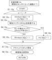
- step 5 shows the steps of the process for obstacle identification performed by the obstacle identification unit 12 receiving obstacle information/parameters OP1[t][M] from on-board sensor(s) as an example, where t denotes time (timestamp/time information) and M denotes a variable M for a matrix of obstacle parameters, and the obstacle identification unit 12 receives obstacle information/parameters OP2[t][N] from external sensor(s), where N is a matrix of obstacle parameters (steps S1, 2_12). Subsequently, the index p is set to zero, n for 1, 2,... N, m for 1, 2,... M and the flag "identified_flg[n]" are set to the value zero (steps S3-4a_12).
- step S6, 7_12 the distance in meters between the obstacle “described” by the detected OP1[t][M] and the detected obstacle OP2[t][N] is determined and a comparison is performed with a threshold "TH_distance" (steps S6, 7_12), which delivers either "YES” if the determined distance is smaller than the threshold, or NO in the other case. If the output is YES, it may further be checked whether attributes are identified. For the latter step, the attribute information of OP2 may be used to identify object class (car, pedestrian, %), size (length, width, etc.), V2X information (only transmitting cars), subclass (car, truck, bus, %), color (white, black, ...), brake light, blinker light, plate number, etc.
- steps S8, 9_12 The logic behind the above steps is that a close distance between an onboard detected obstacle and an external detected obstacle may mean that it is actually the same obstacle, which is further confirmed by attribute check, i.e., if the distance is very close and one or more attributes are identical, the respective identified flags are set to 1, which prevents the externally detected obstacle OP2[t][n] from being registered as OPU[t][p] in steps S10_12 and S11_12 and further warning process flow is executed based on it. In other words, this part filters out the obstacles detected only by the external sensor that are misidentified, which are further processed by the assistance judgment unit 13.
- identified_flg[n] is set to 1.
- the value of identified_flg[n] is compared to the value 0, and if the comparison returns YES, then an OP2[t][n] entry is registered in OPU[t][p] and p is incremented. The process returns to START as if identified_flg[n] was not equal to the value 0.
- Figs. 6a-6c non-exhaustively illustrate examples having different sensor detection areas (different shapes, sizes, etc.) around the host vehicle V.
- the on-board sensor sensing functionality status acquisition unit 14a may determine the accurate and actual sensor detection area SDA of the host vehicle V by using information provided in a database or the like, including sensor specifications such as detection range, detection angle, etc., information from the on-board sensor(s) such as dynamic performance information from the sensor, history of detection results such as maximum distance, maximum angle, etc. Using the information, the sensor field of view (sensor detection area) of the host vehicle V can be determined, and for example, different fields of view as in Figs. 6a-6c can be determined.
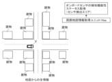
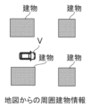
- the surrounding map information acquisition unit 14aa provides map information as shown by Figs. 7a and 7b.
- Fig. 7a shows a case where "all" map information is used, where "all” preferably means that information from a certain radius, etc. around the actual position of the vehicle is used.
- Fig. 7b shows that only surrounding features of the actual position of the vehicle V are used, such as information about the positions and shapes, etc. of buildings, etc. in the immediate surroundings.
- the on-board sensor sensing functionality status acquisition unit 14a can modify the initially determined sensor detection area(s) SDA, for example by reducing parts of the sensor detection area in locations where buildings block the field of view of one or more on-board sensors.
- Figs. 8a-8c Non-exhaustive and schematic examples of the results of such modified sensor detection areas are shown by Figs. 8a-8c.
- the initial sensor detection area SDA is shown, the areas marked in grey are the modified reduced areas, resulting from four exemplary buildings in the vicinity of the position of the ego-vehicle.
- the final sensor detection area SDA is then shown by (a2, b2, c2) for three different exemplary cases. It is clear that the sensor detection area SDA changes due to the movement of the ego-vehicle V and possibly due to the movement of non-static objects that may block the sensor detection area SDA.
- FIG. 9 shows the assistance decision process performed by the assistance decision unit 13a.
- the OPU[p] received from the previous unit is placed in the sensor detection area SDA. This can be done, for example, by projecting the contour of the sensor detection area SDA and the position of the OPU[p] onto a 2D XY map, so that the relationship between position and contour can be examined. Other known calculation methods can be used alternatively or in addition.
- OPU[n] it is checked whether OPU[n] is located inside the sensor detection area SDA, if the result is YES, then mis_flag[p] is set to value 1, if the result is NO, then blindspot_flg[p] is set to value 1. Then, the blind spot warning process and/or the obstacle attention warning process are executed as shown by Figures 10a-c and 11a-c. Note that OPU[n] relates to an obstacle identified as an external sensor detected obstacle.
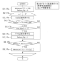
- 10a shows a flow chart in which the steps of possibly activating the blind spot warning are performed in the second driver assistance execution unit 16a.
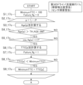
- a minimum TTC value of 1000 is initially set, p is initialized as 1, 2, ... P, and the value of Age[p] is calculated (steps S1-3_16).
- the age value indicates the absolute time length/duration from the first direction of the obstacle to the current/actual time. This calculation can be performed based on known techniques.
- the calculated Age[p] is found to be greater than a predefined threshold TH_AGE_BS, i.e., if YES, then a further check is performed as to whether blindspot_flg[p] is 1, in which case TTC[p] is calculated by known methods (steps S4-6_16), whereas if either of the two previous comparison steps is NO, the process jumps to the comparison of TTC[p] with MinimumTTC (step S7_16). If YES (TTC[p] is less than the MinimumTTC value), then the MinimumTTC value is set to the TTC[p] value (step S8_16), whereas if NO, then the MinimumTTC value is not changed.
- TH_AGE_BS i.e., if YES
- Fig. 10b shows a potential example scenario where the vehicle V is driving along a route and there is a person walking behind a building towards the vehicle's future route (a detected obstacle that can only be detected by an external sensor due to the building blocking the SDA).
- Fig. 10c shows a possible display image displayed to the driver, for example on the screen of the vehicle. In this image, the driver is warned about the person in the blind spot by such an image, whereas the appearance/design of the image may be quite different. Furthermore, a warning sound may be issued.
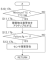
- FIG. 11a further shows a process executed by the third driver assistance execution unit 17a to execute an obstacle attention warning process and/or a sensor failure warning process.
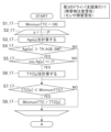
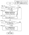
- FIG. 11a shows the first steps of this process up to "A" (steps S1-8_17), after which the process continues as shown in FIG. 11b (steps S9-13_17).
- the threshold TH_AGE_SM is adapted to check whether the sensor failure situation persists, since the obstacle detection algorithm may cause momentary detection failure and the third driver assistance system should not be activated by momentary detection failure.
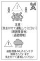
- the MinimumTTC value is compared with a predefined TTC_SM value, which is the TTC threshold of obstacles caused by sensor detection failures, and if the MinimumTTC value is lower (YES), an obstacle attention warning is activated (an exemplary and different design/image or warning may be displayed), and the SensorMissCnt value, which counts sensor failures, is increased and compared with a predefined TH_MissCNT sensor failure count threshold, as shown in the top of Fig. 11c.
- the MinimumTTC value is not lower than TTC_SM (NO)
- the process jumps directly to the comparison of the SensorMissCnt value with the predefined TH_MissCNT sensor failure count threshold.
- a sensor failure warning is activated; if NO, then the sensor failure warning is not activated and the process returns.
- Each sensor failure warning may appear as shown in the lower part of FIG. 11c.
- the sensor detection area SDA can be determined by the above process so that the shape/size/dimension/covered area of the on-board sensor detection area is known to the host vehicle V/control device of the host vehicle at any time.
- FIG. 12b shows a situation in which an object/obstacle is detected in the sensor detection area by the on-board sensor. This can result in normal driver assistance, which in the present disclosure is preferably handled by the first driver assistance execution unit.
- FIG. 12b shows multiple detected obstacles, two of which are inside the sensor detection area (i.e., on-board sensor detection area) and one of which is outside the sensor detection area and can only be detected by the external sensor(s) (V2X information).
- FIG. 12d shows a situation that the present subject matter can advantageously handle compared to the prior art, since one of the obstacles inside the sensor detection area is considered to be detected only by the external sensor(s), even though the on-board sensor(s) should be able to detect this obstacle since it is inside the sensor detection area of the on-board sensor.
- Such a situation then results in two warnings, an obstacle attention warning and a sensor failure warning, which are possible due to the above-described configuration of the control device 1 disclosed herein, in particular the work of the assistance judgment unit and the second and third driver assistance execution units.
- the first embodiment allows a blind spot warning to be issued reliably when an obstacle is in the blind spot of the on-board sensor(s) and the obstacle is detected by the external sensor(s). Furthermore, an obstacle is detected inside the (on-board) sensor detection area (i.e., not in the blind spot area), an obstacle attention warning is issued, and if such an obstacle is detected only by the external sensor(s) and not by the on-board sensor(s), preferably if non-detection occurs more than once within a certain period of time, a sensor failure warning (sensor failure) may be issued. In other words, the present subject matter can actually handle a situation when the on-board sensor cannot detect an obstacle due to a detection failure or the like.
- the ADAS or autonomous driving system provides a warning to the driver, such as a sensor failure condition warning and/or an unreliable status of the ADAS.
- the warning helps the driver understand that ADAS or AD driving is unreliable and that the driver should drive on their own.
- FIG. 13 shows a second embodiment (embodiment 2) that may be an alternative configuration to embodiment 1.
- the functionality described in relation to embodiment 2 may be combined with embodiment 1.
- the control device 1 having the units shown in FIG. 13 differs from Example 1 as follows:
- the assistance judgment unit 13b receives various input information from the on-board sensor detection functionality status acquisition unit 14b, in particular, the assistance judgment unit 13b receives (self-)diagnosis results/information from the on-board sensor(s) or from the respective control programs of the sensor(s) or other units. Using this information, the assistance judgment unit 13b is able to detect a fault in the on-board sensor(s) of the host vehicle V and can notify appropriately. Further details not described in relation to Example 2 shall be considered equivalent or similar to those in Example 1 and described above.
- Example 2 is comparable to Example 1 in that Example 2 can take into account situations where the sensor detection area SDA is not fully reliable or has deteriorated. However, instead of the sensor detection area SDA being modified due to external objects such as buildings, Example 2 takes into account internal sensor failure or deterioration due to mud, rain, etc.
- Figure 14a shows a situation where one of the on-board sensor(s) covering the left rear part of the host vehicle V has completely failed. Such information is provided by a sensor or a sensor control program or a self-diagnosis program/unit (not shown) provided in the host vehicle V or in the control device 1.
- Figure 14a shows one non-limiting example of self-diagnosis from a radar sensor via the CAN bus. Therefore, the sensor detection area of the host vehicle V in Figure 14a does not cover the left rear triangular part marked in grey.
- FIG. 14b Another example is shown in FIG. 14b, where the sensor detection area SDA of a forward vision sensor is partially reduced/degraded due to mud, rain, etc. on the sensor, such as camera, lidar, etc.
- the degraded and newly determined sensor detection area SDA results as shown in the lower part of FIG. 14.
- the determination of the (partially) degraded sensor detection area SDA can be performed, for example, by image analysis as known in the art.
- Fig. 15a is a process showing a situation in which the assistance judgment unit 13b is notified that a whole area fault has been detected, as shown by the example of Fig. 14a.
- steps S1_13b to S8_13b of the workflow in Fig. 15a are executed, which are identical to the steps described in relation to Fig. 9, and therefore the description is omitted.
- the sensor detection area SDA of the steps in Fig. 15a will of course be the sensor detection area SDA resulting from the fault information, as shown by Fig.
- the sensor detection area may be a combination of Fig. 14a and map-based information, for example, as described in Fig. 8.
- the assistance judgment unit 13 will receive both types of information from the on-board sensor detection functionality status acquisition unit 14. Then, as in Fig. 10a, the blind spot warning process is executed, and further warning functions are executed as shown by Fig. 16a and Fig. 16b (steps S1_17b to S13_17b).
- the steps in Fig. 16a and Fig. 16b are similar to Fig. 11a and Fig.
- the failure_flg value is first set to 1 before the comparison of TTC[p] with MinimumTTC.
- the obstacle attention warning is activated after a YES in the comparison of MinimumTTC with TTC_SM, without setting sensormisscnt higher as in Fig. 11b.
- the next step in FIG. 16 is then to check if the failure_flg value is set to 1, and if so, a sensor failure warning is displayed as shown in FIG. 16.
- FIG. 15b is a comparable case to FIG. 15a, but further illustrates the case of a situation where the assistance judgment unit 13b is notified that a partial failure of one or more on-board sensor(s) has occurred, e.g. due to raindrops, snow, mud, etc., with consequences as described in FIG. 14b as one possible example.
- the workflow uses the same method/steps as in FIG. 15a, but the blindspot_flg and miss_flag values are set differently compared to FIG. 15a and FIG. 9, i.e. YES and NO are exchanged.
- the process flow of FIG. 10a is executed with respect to the second assistance execution unit 16b, and the steps of FIG. 16a, b are executed by the third assistance execution unit 17b as described above.
- the embodiments may be combined with each other, i.e., the inputs from the on-board sensor sensing functionality status acquisition units to the assistance decision unit would be combined, either by providing input information of embodiment 1 and embodiment 2, or by having two on-board sensor sensing functionality status acquisition units providing specific information.
- the second and third driver assistance execution units would need to be adapted to be able to execute two different processes as described above, or a combined adaptation process.
- the same considerations regarding possible combinations of embodiment 1 and embodiment 2 apply equally to the following embodiments.
- two or more embodiments of the present disclosure may be combined accordingly.
- Figure 17 shows a third embodiment (embodiment 3) which also takes into account various information from the on-board sensor sensing functionality status acquisition unit 14c, in particular ambient environment information, e.g. regarding weather, time of day, etc.
- the sensor detection area portions marked in grey are impaired or unreliable in terms of their sensor detection function due to adverse weather conditions such as heavy rain that block the respective sensor, e.g. LIDAR, whose information may be received wirelessly by an external information source.
- the illuminance in the surroundings of the vehicle V may be detected based on the time of day, the particular sensor, etc., and when the illuminance is low, the on-board sensor(s), e.g. camera, may be less reliable.
- factors such as those shown in a non-limiting manner in FIG. 18a result in a reduction of the sensor detection area SDA, or at least information that a part or the entire sensor detection area is more unreliable.
- the adapted workflow of FIG. 18b can be executed in the assistance judgment unit 13c using the respective sensor detection area (or reliable parts of the sensor detection area) and the process flow of FIG. 18b (steps S1-8_13c), otherwise the same as described before in FIG. 15, for example.
- step S1-13_17c the process flow executed by the third driver assistance execution unit 17c is shown in Figures 19a and 19b (steps S1-13_17c), which is similar to the process flow of Figures 16a and 16b, except that the sensor fault warning is replaced by a harsh environment warning as illustrated in Figure 19c.
- FIG. 20 shows a fourth embodiment (embodiment 4) as a further modification, in which the assistance judgment unit 17d receives intermediate results/information regarding obstacle detection within the sensor detection area SDA.
- the assistance judgment unit 17d receives intermediate results/information regarding obstacle detection within the sensor detection area SDA.
- Such information is shown in a non-exhaustive list of examples in FIG. 21.
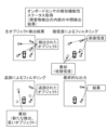
- this may include raw data object detection results as shown in the upper left part of FIG. 21a.
- Such detection results of the on-board sensor(s) are usually first filtered with respect to confidence checks (upper right part of FIG. 21a), as known, and then the detection results are further filtered by tracking the detected object over a period of time (lower left part of FIG. 21a), as known in the art, and then the final result (lower right part of FIG. 21a) is usually produced.
- the detected object at any stage before the final stage as shown in the lower right part of FIG. 21a may be used from the upper left or upper right part or lower left part of FIG. 21a, etc., and input to the assistance judgment unit as "intermediate detection results/information". Therefore, the support judgment workflow as shown in FIG. 21b is executed by the support judgment unit and is modified as follows compared to FIG. 9:
- the assistance judgment unit 13d receives all or part of the intermediate detection results/information from the on-board sensor(s) denoted OPI[Q], then the indexes p and q are set and the respective flag values are set to the value 0. Then the distance between OPU[p] and OPI[q] is calculated and then the distance is compared with a predefined threshold TH_Candidate. If the distance is less than the threshold (YES), the miss_flag[p] value is set to 1, and if the check returns NO, the blindspot_flg[p] is set to a value of 1. Then the blind spot warning procedure continues as described in connection with FIG. 10a and the obstacle caution warning procedure continues as illustrated by FIG. 22.
- OPI[q] is present in close proximity to OPU[p]
- OPI[q] is not present around OPU[p]
- Figures 22a and 22b (steps S1-13_17d) show the workflow as described in relation to Figures 11a and 11b, and the example warning display in Figure 22c is the same as that in Figure 11c.
- FIG. 23 shows a further fifth embodiment (embodiment 5), which is again alternatively arranged with respect to the input to the assistance decision unit 13e, so that the second driver assistance execution unit 16e and the third driver assistance execution unit 17e are also modified.
- This case covers in particular the situation where one detected obstacle blocks part of the sensor detection area SDA, so that further objects/obstacles can only be detected by the external sensor(s), which would normally result in a blind spot warning, for example, in the above embodiment, due to the presence of a detected obstacle in the blind spot area.
- the driver may want to first pay attention to the closer first detected obstacle, so that the driver's safety would be increased if the second (further away) obstacle was not immediately warned by the blind spot warning, or if the warning were to be less distracting to the driver. While the prior art is unable to handle such situations, the present disclosure is able to safely handle such situations, particularly with the configuration of Example 5.
- the assistance judgment unit 13e receives surrounding map information directly or indirectly (from unit 14ee) as in Example 1. The first option is illustrated by FIG. 23.
- the on-board sensor detection functionality status acquisition unit 14e provides input regarding the position and distance of the obstacle(s) detected by the on-board sensor.
- the process of obtaining the information by the on-board sensor detection functionality status acquisition unit 14e is shown in Figure 24a, and the process starts with initializing the index m, Spress_BSW_FLG, which is a predefined threshold for distinguishing whether there is a very close obstacle just in front of or next to the vehicle and activating the weak BSW mode, is set to a value of 0, and then the TTC[m] to the obstacle detected by the on-board sensor is calculated and compared with the predefined threshold TH_TTC (steps S1-4_14e).
- the modified assistance judgment unit workflow is shown by Fig. 24b, including steps S1 to S7_13e. It starts with initializing index p and setting the values of blindspot_flg[p] and weak_blindspot_flg[p] to 0. Then, the Spress_BSW_FLG value is checked whether it is 1 or not. If the Spress_BSW_FLG value is 1 (YES), weak_blindspot_flg[p] is set to the value 1, otherwise (NO), blindspot_flg[p] is set to the value 1. Then, the blind spot warning and weak blind spot warning processes are executed, and Fig. 10a is the case of blind spot warning and weak blind spot warning shown in Fig. 25b (same as in Fig. 10c), and Fig. 25a is the case of weak blind spot warning.
- FIG. 25a shows a modified third driver assistance execution warning process (steps S1-10_17e) that issues a weak blind spot warning comparable to the blind spot warning of FIG. 10a, but checks whether the weak blind spot flag is 1, and thus may result in a weak blind spot warning, as exemplarily shown for FIG. 25c.
- the blind spot warning is shown without an audio warning, as in FIG. 25c, while the standard blind spot warning may issue an audio warning, for example as shown in FIG. 25b.
- Example 5 particularly covers a situation where the prior art has difficulty in prioritizing warnings.
- the host vehicle V when the host vehicle V is running in a forward direction, it is a very dangerous situation if there is a first obstacle in front of the host vehicle V at a short distance to the host vehicle V.
- the first obstacle in front of the host vehicle blocks the detection area of the sensor, so that other obstacles located behind the first obstacle, such as a second obstacle, a third obstacle, etc., can be detected only by V2X.
- this situation can occur when a first nearby obstacle blocks the sensor view, thereby generating a blind spot, in which further obstacles (farther away) may be located, and the further obstacles can be detected only by V2X due to the blind spot generated by the first obstacle.
- a method, device and/or computer program may be provided that improves driving safety, particularly for drivers of vehicles.
- embodiments of the present disclosure may take the form of an entirely hardware embodiment, an entirely software embodiment (including firmware, resident software, microcode, etc.), or an embodiment combining software and hardware aspects.
- embodiments of the present disclosure may take the form of a computer program product on a computer readable medium having computer executable program code embodied in the medium.
- arrows in the drawings may be used to represent communication, transfers, or other activity involving two or more entities.
- a bidirectional arrow generally indicates that activity can occur in both directions (e.g., a command/request in one direction and a corresponding reply in the other direction, or peer-to-peer communication initiated by either entity), although in some situations activity may not necessarily occur in both directions.
- a unidirectional arrow may generally indicate activity that is exclusive or dominant in one direction, in certain circumstances such directional activity may actually involve activity in both directions (e.g., a message from sender to receiver and an acknowledgment from receiver back to sender, or the establishment of a connection before a transfer and the termination of a connection after a transfer). Therefore, arrows of this type used in particular drawings to represent particular activities are illustrative and should not be considered limiting.
- Computer-executable program code may be provided to a processor of a general-purpose computer, special-purpose computer, or other programmable data processing device to produce a particular machine such that the program code, executing via the processor of the computer or other programmable data processing device, creates means for implementing the functions/operations/output specified in one or more blocks of the flowcharts, block diagrams, figures, and/or written descriptions.
- These computer-executable program codes may also be stored in a computer-readable memory, and the computer-executable program codes may instruct a computer or other programmable data processing device to function in a particular manner such that the program code stored in the computer-readable memory produces a product that includes instruction means that implement the functions/operations/output specified in the flowcharts, block diagram block(s), figures, and/or written descriptions.
- the computer-executable program code may also be loaded onto a computer or other programmable data processing apparatus and run on the computer or other programmable data processing apparatus to generate a computer-implemented process such that the program code running on the computer or other programmable data processing apparatus provides steps that implement the functions/operations/outputs specified in the flowcharts, block diagram block(s), figures, and/or written descriptions.
- the steps or operations implemented by the computer program may be combined with steps or operations implemented by an operator or human to perform the embodiments.
- Communication networks may generally include public and/or private networks, may include local area networks, wide area networks, metropolitan area networks, storage, and/or other types of networks, and may employ communication technologies including, but in no way limited to, analog technologies, digital technologies, optical technologies, wireless technologies (e.g., Bluetooth), networking technologies, and internetworking technologies.
- communication technologies including, but in no way limited to, analog technologies, digital technologies, optical technologies, wireless technologies (e.g., Bluetooth), networking technologies, and internetworking technologies.
- devices may use communication protocols and messages (e.g., messages created, transmitted, received, stored, and/or processed by the devices) and that such messages may be conveyed over a communications network or medium.
- communication protocols and messages e.g., messages created, transmitted, received, stored, and/or processed by the devices
- a communication message may generally include, but is not limited to, a frame, a packet, a datagram, a user datagram, a cell, or other type of communication message.
- references to particular communications protocols are exemplary and that alternative embodiments may employ variations of such communications protocols (e.g., modifications or extensions of the protocols as may be made from time to time) or other protocols, whether now known or that may be developed in the future, as appropriate.
- logic flows may be described herein to illustrate various aspects, and that the logic flows should not be construed to limit the disclosure to any particular logic flow or implementation of logic.
- the described logic may be divided into different logic blocks (e.g., programs, modules, functions, or subroutines) without changing the overall result.
- logic elements may be added, modified, omitted, performed in a different order, or implemented using various logic constructs (e.g., logic gates, looping primitives, conditional logic, and other logic constructs) without changing the overall result.
- logic constructs e.g., logic gates, looping primitives, conditional logic, and other logic constructs
- the present disclosure may be embodied in many different forms, including, but not limited to, computer program logic for use with a processor (e.g., a microprocessor, microcontroller, digital signal processor, or general purpose computer), programmable logic for use with a programmable logic device (e.g., a Field Programmable Gate Array (FPGA) or other PLD), discrete components, integrated circuits (e.g., an Application Specific Integrated Circuit (ASIC)), or any other means including any combination thereof.
- Computer program logic implementing some or all of the described functionality is typically implemented as a set of computer program instructions that are converted into a computer executable form, stored intact on a computer readable medium, and executed by a microprocessor under the control of an operating system.
- Hardware-based logic implementing some or all of the described functionality may be implemented using one or more appropriately configured FPGAs.
- Computer program logic implementing all or part of the functionality previously described herein may be embodied in various forms, including, but in no way limited to, source code form, computer executable form, and various intermediate forms (e.g., forms produced by an assembler, compiler, linker, or locator).
- Source code may include a series of computer program instructions implemented in any of a variety of programming languages (e.g., object code, assembly language, or high-level languages such as Fortran, C, C++, JAVA, or HTML) used with a variety of operating systems or operating environments.
- the source code may define and use various data structures and communication messages.
- the source code may be in a computer-executable form (e.g., via an interpreter) or the source code may be converted into a computer-executable form (e.g., via a translator, assembler, or compiler).
- Computer executable program code for carrying out operations of embodiments of the present disclosure may be written in an object-oriented, scripting, or non-scripting programming language, such as Java, Perl, Smalltalk, C++, etc.
- computer program code for carrying out operations of embodiments may also be written in a conventional procedural programming language, such as the "C" programming language or a similar programming language.
- Computer program logic implementing all or part of the functionality previously described herein may execute at different times (e.g., simultaneously) on a single processor, or may execute at the same or different times on multiple processors, and may execute under a single operating system process/thread or under different operating system processes/threads.
- computer process may generally refer to the execution of a set of computer program instructions, regardless of whether different computer processes are executed on the same processor or on different processors, and regardless of whether different computer processes are executed under the same operating system process/thread or under different operating system processes/threads.
- a computer program may be fixed, either permanently or temporarily, in any form (e.g., source code form, computer executable form, or intermediate form) on a tangible storage medium, such as a semiconductor memory device (e.g., RAM, ROM, PROM, EEPROM, or flash programmable RAM), a magnetic memory device (e.g., a diskette or fixed disk), an optical memory device (e.g., a CD-ROM), a PC card (e.g., a PCMCIA card), or other memory device.
- a semiconductor memory device e.g., RAM, ROM, PROM, EEPROM, or flash programmable RAM
- a magnetic memory device e.g., a diskette or fixed disk
- an optical memory device e.g., a CD-ROM
- PC card e.g., a PCMCIA card
- a computer program may be fixed in any form in a signal that is transmittable to a computer using any of a variety of communication technologies, including, but in no way limited to, analog, digital, optical, wireless (e.g., Bluetooth), networking, and internetworking technologies.
- communication technologies including, but in no way limited to, analog, digital, optical, wireless (e.g., Bluetooth), networking, and internetworking technologies.
- the computer program may be distributed in any form, such as on a removable storage medium accompanied by printed or electronic documentation (e.g., commercially available software), or may be preloaded with the computer system (e.g., on a system ROM or fixed disk), or may be distributed from a server or bulletin board via a communications system (e.g., the Internet or the World Wide Web).
- a communications system e.g., the Internet or the World Wide Web.
- Hardware logic including programmable logic used in conjunction with a programmable logic device
- implementing all or a portion of the functionality previously described herein may be designed using traditional manual methods, or may be electronically designed, captured, simulated, or documented using a variety of tools, such as Computer Aided Design (CAD), hardware description languages (e.g., VHDL or AHDL), or PLD programming languages (e.g., PALASM, ABEL, or CUPL).
- CAD Computer Aided Design
- hardware description languages e.g., VHDL or AHDL
- PLD programming languages e.g., PALASM, ABEL, or CUPL
- the computer readable medium may be, for example, but not limited to, an electronic, magnetic, optical, electromagnetic, infrared, or semiconductor system, apparatus, device, or medium.
- Computer readable media include, but are not limited to, electrical connections having one or more wires, or other tangible storage media, such as a portable computer diskette, a hard disk, a random access memory (RAM), a read-only memory (ROM), an erasable programmable read-only memory (EPROM, or flash memory), a compact disc read-only memory (CD-ROM), or other optical or magnetic storage device.
- RAM random access memory
- ROM read-only memory
- EPROM erasable programmable read-only memory
- CD-ROM compact disc read-only memory
- the programmable logic may be fixed, either permanently or temporarily, in a tangible storage medium, such as a semiconductor memory device (e.g., RAM, ROM, PROM, EEPROM, or flash programmable RAM), a magnetic memory device (e.g., a diskette or fixed disk), an optical memory device (e.g., a CD-ROM), or other memory device.
- a semiconductor memory device e.g., RAM, ROM, PROM, EEPROM, or flash programmable RAM
- a magnetic memory device e.g., a diskette or fixed disk
- an optical memory device e.g., a CD-ROM
- the programmable logic may be fixed with signals that are transmittable to a computer using any of a variety of communication technologies, including, but in no way limited to, analog, digital, optical, wireless (e.g., Bluetooth), networking, and internetworking technologies.
- communication technologies including, but in no way limited to, analog, digital, optical, wireless (e.g., Bluetooth), networking, and internetworking technologies.
- the programmable logic may be distributed on a removable storage medium (e.g., commercially available software) accompanied by printed or electronic documentation, may be preloaded with the computer system (e.g., on a system ROM or fixed disk), or may be distributed from a server or bulletin board via a communications system (e.g., the Internet or the World Wide Web).
- a communications system e.g., the Internet or the World Wide Web.
- some aspects may be implemented as a combination of both software (e.g., a computer program product) and hardware. Still other embodiments thereof may be implemented entirely in hardware or entirely in software.
Landscapes
- Physics & Mathematics (AREA)
- General Physics & Mathematics (AREA)
- Traffic Control Systems (AREA)
Abstract
本主題は、車両のドライバ支援システムを制御する制御デバイス、方法、及びコンピュータプログラム製品に関する。
Description
本主題は、車両のドライバ支援システムを制御する制御デバイス、方法、及びコンピュータプログラム製品に関する。
現行の先進運転支援システム(advanced driver assistance system:ADAS)は、車両に搭載されたオンボードセンサを使用して、車両の周囲のエリア内の障害物を検出し、衝突のリスクがある場合に介入する。誤トリガを回避するために、障害物を継続して何度か観測/検出してから、介入をアクティブ化する。これにより、例えば、検出される障害物の位置及び速度の計算の信頼性が高まる。しかしながら、繰り返される検出は、ある一定の観測時間を必要とするため、例えば、次いでADASが大きくブレーキをかけざるを得ない場合があり、このことが、車両のドライバに不快感をもたらし得る。このような状況は、特に、車両の前方または背後のブラインドスポットから障害物が突然現れる場合に起こり得る。このような状況を軽減する可能性があるものは、V2X(車両万物間(vehicle to everything))通信を使用して、車両のオンボードセンサの検出範囲を越える情報を取得することである。
特許文献1は、車両のカメラデバイスの視野に入る移動オブジェクトを検出するシステム及び装置を記載している。このシステムは、車両に搭載された車両自体の測位デバイスと、移動オブジェクトが所有するモバイル端末から定期的に受信される位置情報とを使用する。モバイルユニットのモバイル端末の位置情報と、車両自らの進行方向とに基づいて、移動オブジェクトがカメラの視野に入ったときに、カメラによってキャプチャされた画像に、モバイルユニットを検出するエリアが設定され、モバイルユニットが検出される。
しかしながら、外部デバイスによるADASの直接制御は困難であり、それは、V2X情報の遅延、伝送不安定、及び悪意のある伝送に起因する、外部デバイスの誤ったアクティブ化を回避することが不可欠だからである。したがって、V2X情報を評価し(例えば、外部デバイスの仕様及び適用範囲の観点で)、かつV2X情報の好適なパラメータのみを使用して、ADAS機能を開始することが重要である。
上記の問題は以前に対処されているが、オンボードセンサから生じる情報とV2X情報(外部センサ情報)との混合の使用は、本開示によって対処されるさらなる課題をもたらす。
より具体的には、例えば、V2Xの典型的な適用シナリオのうちの1つは、ブラインドスポット警告に関し、これは、オンボードセンサ(複数可)のブラインドスポットエリアにおいて障害物が検出されたときに、ブラインドスポット警告がドライバに警告することを意味する。
特許文献2は、自車両センサに加えてV2X情報を使用することによる、自車両のドライバへのこのようなブラインドスポット警告を記載している。このシステムは、次の論理を使用する。障害物が、両方、すなわちオンボードセンサ(複数可)及びV2X、によって検出された場合に、障害物は、ブラインドスポット(すなわち、ブラインドスポットエリア)の内部の障害物とみなされない。一方、障害物がV2Xのみによって検出された場合に、障害物は、ブラインドスポットエリアの内部の障害物とみなされる。
しかしながら、運転中に起こり得るいくつかの状況は、当該手法によっては解決/対処されない。例えば、
a)この手法は、オンボードセンサが検出失敗などに起因して障害物を検出することができない状況を処理することができない。障害物がV2Xによってのみ検出された場合であるが、当該検出された障害物がオンボードセンサの検知エリアの内部にある(ブラインドスポットエリアにない)場合に、ADASまたは自動運転システム(automated driving system:AD)は、センサ障害状況警告、及び/またはADASの信頼性のないステータスなどの警告を、ドライバに提供するべきである。この警告は、その場合に、ADAS運転またはAD運転に信頼性がないこと、及びドライバが自力で運転すべきであること、を理解するように、ドライバをサポートする。
b)さらに、上記の説明された先行技術の手法は、警告の優先順位付けについての困難を有する。例えば、自車両が前向きの方向に走っているときに、自車両の前方に、自車両までの短い距離に第1の障害物がある場合は、非常に危険な状況である。この状況では、自車両の前方の第1の障害物がセンサの検知エリアを妨害することから、次いで、第1の障害物の背後に位置する他の第2の障害物、第3の障害物、などの障害物が、V2Xのみによって検出され得る。換言すると、この状況は、第1の近接した障害物がセンサ視界を遮断し、これによって、巨大なブラインドスポットを生成する場合に起こり得るものであり、このブラインドスポットには、さらなる障害物(より遠く離れた)が位置する可能性があり、さらなる障害物は、第1の障害物によって生成されたブラインドスポットに起因して、V2Xのみによって検出され得る。このような状況において、当然ながら、ドライバは、自車両が既に、非常に近接した第1の障害物に直面した危険な状況にあるため、第2の障害物、第3の障害物、などの障害物(より遠く離れた)に対する(強い)ブラインドスポット警告を受け入れないはずであり、その場合に、ドライバは、この瞬間にさほど緊急性がないブラインドスポット警告に気を逸らされるべきではない。
本明細書に記載された主題は、ドライバ支援システム、及び/または自動運転システムが備えられた車両の運転安全性を向上させる技術的目的に対処する。特に、障害物がオンボードセンサ(複数可)によってではなく、V2Xによって検出される状況において、安全性が高まる。この目的は、独立請求項の主題によって達成される。さらなる好ましい発展が、従属請求項によって記載されている。
添付の請求項に明記された主題によれば、制御デバイス、方法、及びコンピュータプログラム製品が提案される。さらに、このようなコンピュータプログラム製品の制御デバイスが備えられた自車両もまた、本開示の一部である。特に、本明細書に開示された主題は、自車両のオンボードセンサ(複数可)ではなく、V2Xによる障害物の検出が発生した場合のドライバ支援システムまたは自動運転システムの特性を向上させる。
開示された主題によって制御されるドライバ支援システムは、例えば、自動緊急制動(automatic emergency braking:AEB)、アダプティブクルーズコントロール(adaptive cruise control:ACC)、または車線変更支援(lane change assist:LCA)であり得る。また、他のタイプのドライバ支援システムが、提案された主題と組み合わされてもよい。このシステムはまた、自動運転機能を含んでもよいし、さらに有してもよい。
本開示の一態様は、車両、すなわち自車両、のドライバ支援システムを制御する制御デバイスに関し、制御デバイスは、
センサ検出エリアをカバーする1つ以上のオンボードセンサによって検出された障害物情報と、センサ検出エリアの外部のエリアであるブラインドスポットエリアとを取得するように構成されたオンボードセンサ障害物情報取得ユニットを備える。換言すると、センサ検出エリアという用語は、自車両のオンボードセンサ(複数可)の視野によってカバーされるエリアに使用され、ブラインドスポットまたはブラインドスポットエリアは、車両のオンボードセンサ(複数可)によってカバーされないエリアである。ただし、外部センサ、すなわち自車両に提供されるV2X情報、は、ブラインドスポットエリアをカバーすることができる。
センサ検出エリアをカバーする1つ以上のオンボードセンサによって検出された障害物情報と、センサ検出エリアの外部のエリアであるブラインドスポットエリアとを取得するように構成されたオンボードセンサ障害物情報取得ユニットを備える。換言すると、センサ検出エリアという用語は、自車両のオンボードセンサ(複数可)の視野によってカバーされるエリアに使用され、ブラインドスポットまたはブラインドスポットエリアは、車両のオンボードセンサ(複数可)によってカバーされないエリアである。ただし、外部センサ、すなわち自車両に提供されるV2X情報、は、ブラインドスポットエリアをカバーすることができる。
さらに、制御デバイスは、1つ以上のオンボードセンサの機能性ステータス(機能性ステータス情報)を取得するように構成されたオンボードセンサの検知機能性ステータス取得ユニットを有する。以下、種々の例に関連して、機能性ステータスについて記載する。機能性ステータスは、オンボードセンサ(複数可)の信頼性情報、種々の要因に起因するオンボードセンサの検出エリアの劣化、自車両のセンサ検出エリアのサイズ、形状、次元などをカバーし得る。
さらに、制御デバイスは、1つ以上の外部センサから障害物情報を取得するように構成された外部センサ障害物情報取得ユニットを備え、障害物情報は、特に、他の車両に搭載されたセンサなどの他の外部センサから、道路脇センサユニットなどへの無線の受信されたV2X情報を意味し得る。
そして、制御デバイスは、外部センサ検出障害物がブラインドスポットエリアの内部にあるか否かを判定するように構成された支援判断ユニットを含む。外部センサ検出障害物という用語は、特に、外部センサのみによって検出されたオブジェクトや障害物を指すものとする。追加的または代替的に、オンボードセンサと外部センサとの両方が障害物を検出したが、外部センサの信頼性がオンボードセンサと比較してより高い、という状況も、この制御デバイスはカバーし得る。外部センサの信頼性がオンボードセンサと比較してより高い、という状況は、例えば、自己診断によってオンボードセンサの故障が発見されたとき、または悪天候によりオンボードセンサ(複数可)の信頼性が低下し得る場合に、制御デバイスの任意のユニットまたはインスタンスによって判断されてもよい。このことは、好ましくは、機能性ステータス情報に含まれ得る。
好ましくは、センサ検出エリアの実際の形状が考慮されているという意味や、その信頼性などを含み得る機能性ステータス情報によって/に対して、外部センサ検出障害物がブラインドスポットエリアの内部にあるか否かの検査が実行される。このような情報は、好ましくは、支援判断ユニットへの入力から、特にオンボードセンサの検知機能性ステータス取得ユニットから、生じる。
支援判断ユニットによって判定された情報に基づいて、制御デバイスは、自車両のドライバにさらなる有用な出力を提供することが可能になり、それにより、安全性が高まる。
好ましくは、制御デバイスは、さらに、センサによって検出された障害物を識別するように構成された障害物識別ユニットを含んでもよく、識別は、障害物のタイプ、障害物のクラス、異なるセンサによって検出された2つの障害物が同じであるかどうかなどを識別すること、などを含んでもよい。これにより、制御デバイスの精度がさらに高まり、それゆえ、信頼性及び安全性が向上し得る。
さらに、制御デバイスは、
オンボードセンサ(複数可)によって検出された障害物に関するオンボードセンサ障害物情報であって、タイプ、サイズ、ポーズ、速度などのような、様々なデータを含むオンボードセンサ障害物情報に基づいてドライバ支援を実行するように構成された第1のドライバ支援実行ユニットと、
支援判断ユニットが、ブラインドスポットエリアに外部センサ検出障害物があると判定する場合に、好ましくはブラインドスポットエリアについて、ドライバ支援を実行するように構成された第2のドライバ支援実行ユニットと、
支援判断ユニットが、センサ検出エリア内に外部センサ検出障害物があるが、ブラインドスポットエリアにはないと判定する場合に、ドライバ支援を実行するように構成された第3のドライバ支援実行ユニットとを含む。
ドライバ支援はまた、自車両に表示される視覚ガイダンス、音声などの、種々のタイプのガイダンス、及び/または警告を発することを含んでもよい。
好ましくは、支援判断ユニットは、機能性ステータス情報、オンボード(複数可)に関して判定された信頼性、及び/またはリスクに基づいて、外部センサ検出障害物がブラインドスポットエリアにあるか否かを判定するように構成されてもよい。換言すると、この判定は、好ましくは、支援判断ユニットへの入力に基づいて行われ、入力は、図の説明において実施例に関連して説明するように、様々なデータを含んでもよい。
好ましくは、制御デバイスは、オドメトリ、衛星ナビゲーションシステムなどによって提供され得る、速度データ、方向データ、及び他のデータを含んでよく、自車両の運転挙動を取得するように構成された運転挙動取得ユニットを含んでもよい。運転挙動取得ユニットが制御デバイスの一部である場合に、第1のドライバ支援実行ユニットは、オンボードセンサ障害物情報及び運転挙動情報に基づいてドライバ支援を実行するように構成されてもよい。
種々のドライバ支援実行ユニットを設けることは、支援判断ユニットの情報を実践することができ、特にこの情報を使用してドライバと通信することができ、その結果、運転安全性が高まる、という利点をもたらす。
さらに、以下の変更例が提供されてもよい。
オンボードセンサの検知機能性ステータス取得ユニットが、1つ以上のオンボードセンサのセンサ検出エリアを取得するように構成され、
支援判断ユニットが、外部センサ検出障害物の位置と、センサ検出エリアとに基づいて、外部センサ検出障害物がブラインドスポットエリアにあるか否かを判定するように構成され、
第2のドライバ支援実行ユニットが、外部センサ検出障害物が検知エリアの外部に存在する/ある場合に、好ましくは信頼性及びリスクに基づいて、自車両のドライバにブラインドスポット警告を送信するように構成され、
第3のドライバ支援実行ユニットが、外部センサ検出障害物が検知エリア(センサ検出エリア)の内部に存在する/ある場合に、好ましくは信頼性及びリスクに基づいて、ドライバに障害物注意警告を送信するように構成される。
支援判断ユニットが、外部センサ検出障害物の位置と、センサ検出エリアとに基づいて、外部センサ検出障害物がブラインドスポットエリアにあるか否かを判定するように構成され、
第2のドライバ支援実行ユニットが、外部センサ検出障害物が検知エリアの外部に存在する/ある場合に、好ましくは信頼性及びリスクに基づいて、自車両のドライバにブラインドスポット警告を送信するように構成され、
第3のドライバ支援実行ユニットが、外部センサ検出障害物が検知エリア(センサ検出エリア)の内部に存在する/ある場合に、好ましくは信頼性及びリスクに基づいて、ドライバに障害物注意警告を送信するように構成される。
この好ましい変更例において、オンボードセンサの検知機能性ステータス取得ユニットから支援判断ユニットへの入力は、特に、センサ検出エリアの判定、すなわち、センサ検出エリアのサイズ、形状、次元、位置などに関するものである。その場合に、運転の安全性が高まり、第2のドライバ支援実行ユニットは、特に、外部センサ検出障害物が、判定されたセンサ検出エリアの外部で検出された場合に、ブラインドスポット警告を発することができる。なお、センサ検出エリアは、自車両の移動、自車両の周囲の変化などに起因して、時々刻々と変化し得るため、センサ検出エリアは、新たな情報ごとに、またはある一定の周期でリフレッシュされる。さらに、第3のドライバ支援実行ユニットは、外部センサ検出障害物がセンサ検出エリアの内部にある場合に、ドライバに障害物注意警告を発することができる。換言すると、ドライバにより詳細な情報を提供するように、種々のシナリオがカバーされる。
さらに、好ましくは、第3のドライバ支援実行ユニットは、外部センサ検出障害物が、閾値よりも多くの回数、検知エリアの内部で検出された場合に、追加的にセンサ障害警告を送信するように構成されてもよい。閾値は、事前に設定されてもよい。代替的に、閾値は、センサ失敗カウンタによって、または2回以上の「センサ失敗」が起こるある一定期間によって置き換えられてもよく、センサ失敗は、オンボードセンサ(複数可)が、オンボードセンサのセンサ検出エリアの内部の障害物を検出することに失敗し、かつこの障害物が外部センサによってのみ検出されたことを意味することを含むものとする。これにより、制御デバイスの信頼性、それゆえ安全性が高まる。
さらに、本開示に提供及び記載された制御デバイスの変更例及び態様の任意のものに、以下の変更例が提供されてもよい。オンボードセンサの検知機能性ステータス取得ユニットは、オンボードセンサ(複数可)の搭載位置、検出範囲、及び/または検出角度から、センサ検出エリアを判定するように構成される。
さらに、本開示に提供及び記載された制御デバイスの変更例及び態様の任意のものに、以下の変更例が提供されてもよい。地図情報から、周囲建物の位置(複数可)及び形状の情報を取得するように構成された周囲地図情報取得ユニットが設けられ、オンボードセンサの検知機能性ステータス取得ユニットは、追加的に建物情報を使用してセンサ検出エリアを計算するように構成される。建物情報はまた、木、壁、自然構造物などのような、自車両の周囲にあるあらゆる静的(または動的)オブジェクトなどの、建物に関する情報以外の他の情報をカバーしてもよい。このさらなる情報を用いると、例えば建物は自車両のセンサ検出エリアを遮断することで、自車両のセンサ検出エリアを制限/縮小し得るため、センサ検出エリアをより正確に判定することが可能である。
上記の態様(複数可)のさらなる好ましい変更例は、以下を含んでもよい。
オンボードセンサの検知機能性ステータス取得ユニットは、オンボードセンサ(複数可)の(自己)診断情報を取得するように構成され、(自己)診断情報は、オンボードセンサ(複数可)によって、または診断を実行するそれぞれのユニットから、または障害物検出ソフトウェアプログラム上からなど、提供されてもよく、
支援判断ユニットは、自己診断情報に基づいて、外部センサ検出障害物がブラインドスポットエリアにあるか否かを判定するように構成され、
第2のドライバ支援実行ユニットは、外部センサ検出障害物が存在し、かつ自己診断情報が正常ステータスを示す場合に、好ましくは信頼性及びリスクに基づいて、ドライバにブラインドスポット警告を送信するように構成され、
第3のドライバ支援実行ユニットは、外部センサ検出障害物が存在し、かつ自己診断情報が異常ステータスを示す場合に、好ましくは信頼性及びリスクに基づいて、ドライバに障害物注意警告及びセンサ障害警告を送信するように構成される。
支援判断ユニットは、自己診断情報に基づいて、外部センサ検出障害物がブラインドスポットエリアにあるか否かを判定するように構成され、
第2のドライバ支援実行ユニットは、外部センサ検出障害物が存在し、かつ自己診断情報が正常ステータスを示す場合に、好ましくは信頼性及びリスクに基づいて、ドライバにブラインドスポット警告を送信するように構成され、
第3のドライバ支援実行ユニットは、外部センサ検出障害物が存在し、かつ自己診断情報が異常ステータスを示す場合に、好ましくは信頼性及びリスクに基づいて、ドライバに障害物注意警告及びセンサ障害警告を送信するように構成される。
この変更例は、オンボードセンサ障害などに起因してセンサ検出エリアが縮小される状況をカバーすることができ、これを使用して、ドライバ支援実行ユニットの挙動を適応させることができる。
好ましくは、
オンボードセンサの検知機能性ステータス取得ユニットは、1つ以上の無効なセンサ検出エリアを含む自己診断情報を取得するように構成され、
支援判断ユニットは、検出された障害物の位置と、1つ以上の無効な検知エリアとに基づいて、外部センサ検出障害物がブラインドスポットエリアにあるか否かを判定するように構成され、
第2のドライバ支援実行ユニットは、外部センサ検出障害物が無効なセンサ検出エリアの外部に存在する場合に、好ましくは信頼性及びリスクに基づいて、ドライバに、ブラインドスポット警告を送信するように構成され、
第3のドライバ支援実行ユニットは、外部センサ検出障害物が、本技術分野で知られており、かつ、これ以上本明細書に記載されない公知の泥または雨滴検出アルゴリズムによって自動抽出された無効なセンサ検出エリアのうちの1つ以上の内部に存在する場合に、好ましくは信頼性及びリスクに基づいて、ドライバに、センサ障害警告及び障害物注意警告を送信するように構成される。
この変更例は、オンボードセンサ障害などに起因してセンサ検出エリアが縮小される状況をカバーすることができ、これを使用して、ドライバ支援実行ユニットの挙動を適応させることができる。
上記の態様(複数可)のさらなる好ましい変更例は、以下を含んでもよい。
オンボードセンサの検知機能性ステータス取得ユニットは、周囲環境情報を取得するように構成され、
支援判断ユニットは、センサの仕様(オンボードセンサのタイプ、視野、搭載ポーズなどを含み得る)及び環境情報に基づいて、外部センサ検出障害物がブラインドスポットエリアにあるか否かを判定するように構成され、
第2のドライバ支援実行ユニットは、外部センサ検出障害物が存在し、かつ環境が(オンボードセンサにとって)過酷条件として分類されない場合に、好ましくは信頼性及びリスクに基づいて、ドライバに、ブラインドスポット警告を送信するように構成され(好ましくは、検出結果の信頼性が知られている方法で十分に確証されている場合、及び/または、状況が、既知の手順に基づいて判定することもできる所定以上のリスクを有すると識別された場合にのみ、警告が発せられ得ることを意味する)、
第3のドライバ支援実行ユニットは、外部センサ検出障害物が存在し、かつ環境が(オンボードセンサにとって)過酷条件として分類される場合に、好ましくは信頼性及びリスクに基づいて、ドライバに障害物注意警告及び過酷環境警告を送信するように構成される。
過酷条件を種々のカテゴリに分類することを、リアルタイムに、例えば所定の方式、テーブルなどに基づいて、実行することができる。
この変更例は、大雨、雪、暗いエリアなどの外部条件に起因して、センサ検出エリアが縮小されるか、またはオンボードセンサ(複数可)の検出にさほど信頼性がない状況をカバーすることができ、これを使用して、ドライバ支援実行ユニットの挙動を適応させることができる。
好ましくは、オンボードセンサの検知機能性ステータス取得ユニットは、周囲環境情報として天候情報を取得するように構成される。
好ましくは、オンボードセンサの検知機能性ステータス取得ユニットは、周囲環境情報として時刻情報を取得するように構成される。
上記の態様(複数可)のさらなる好ましい変更例は、以下を含んでもよい。
オンボードセンサの検知機能性ステータス取得ユニットは、例えば障害物検出プログラム/アルゴリズムから、中間検出情報を取得するように構成され、
支援判断ユニットは、位置と中間検出情報の位置とに基づいて、外部センサ検出障害物がブラインドスポットエリアにあるか否かを判定するように構成され、
第2のドライバ支援実行ユニットは、中間検出情報が外部センサ検出障害物に近接して存在しない場合に、好ましくは、信頼性及びリスクに基づいて、ドライバにブラインドスポット警告を送信するように構成され、
第3のドライバ支援実行ユニットは、中間検出情報が外部センサ検出障害物に近接して存在する場合に、好ましくは信頼性及びリスクに基づいて、ドライバに障害物注意警告を送信するように構成される。
支援判断ユニットは、位置と中間検出情報の位置とに基づいて、外部センサ検出障害物がブラインドスポットエリアにあるか否かを判定するように構成され、
第2のドライバ支援実行ユニットは、中間検出情報が外部センサ検出障害物に近接して存在しない場合に、好ましくは、信頼性及びリスクに基づいて、ドライバにブラインドスポット警告を送信するように構成され、
第3のドライバ支援実行ユニットは、中間検出情報が外部センサ検出障害物に近接して存在する場合に、好ましくは信頼性及びリスクに基づいて、ドライバに障害物注意警告を送信するように構成される。
このような変更例は、オブジェクト検出手順(当該技術分野で知られているような)中の可能な中間ステップから生じ、かつ、検出されたオブジェクトに関する生データまたは半分処理された生データであり得る、中間(検出)情報を使用する。換言すると、特に検出と警告出力との間の時間を増大させ得る、あり得る検出されたアーチファクトが、支援判断処理に含まれ得る場合がカバーされ、この結果、ドライバは、早期に警告され得る(警告の基礎となる検出が後に擬陽性と見なされ得るとしても)。
上記の態様(複数可)のさらなる好ましい変更例は、以下を含んでもよい。
オンボードセンサの検知機能性ステータス取得ユニットは、オンボードセンサ(複数可)によって検出されているオンボードセンサ障害物の位置を取得し、かつ好ましくは、それによってもたらされるリスクを評価するように構成され、
支援判断ユニットは、検出されたオンボードセンサ障害物までの距離に基づいて、外部センサ検出障害物がブラインドスポットエリアにあるか否かを判定するように構成され、
第2のドライバ支援実行ユニットは、好ましくは所定の閾値距離によって検査されて、最も近接したオンボードセンサ障害物が近接していない場合に、好ましくは信頼性及びリスクに基づいて、ドライバにブラインドスポット警告を送信するように構成され、
第3のドライバ支援実行ユニットは、最も近接したオンボードセンサ障害物の距離が近接している、例えば所定の距離未満で近接している、場合に、好ましくは信頼性及びリスクに基づいて、ドライバに弱い警告を送信するように構成される。
この変更例は、例えば同じく、センサ検出エリアが第1の検出された障害物の存在に起因して縮小され得るという事実に起因して、特に、2つの障害物が、1つはオンボードセンサによって、また別の1つは外部センサのみによって検出される状況に対処することができる。このような状況において、第1のオンボードセンサによって検出された障害物が非常に近接しており、それゆえドライバに(高い)リスクをもたらす場合に、制御デバイスは、ブラインドスポットエリアの第2の検出された障害物について強い警報を提供しなくてもよく、それは、これが第1の(非常に近接した)検出された障害物に対処しようとするドライバの試みからドライバの気を逸らし得るからである。
さらに、好ましくは、自車両の周りの道路構造情報を取得するように構成された周囲地図取得ユニットが設けられてもよく、支援判断ユニットは、自車両が交差点内にいる場合に、外部センサ検出障害物がブラインドスポットエリアの内部にあると判定するように構成される。
さらに、好ましくは、第2の運転支援は、ドライバに障害物のタイプ及び方向を示すように構成された警告システムである。
さらに、好ましくは、第2の運転支援及び第3の運転支援は、警告判断にオブジェクト追跡時刻情報を使用するように構成される。
さらに、好ましくは、外部センサ障害物情報取得ユニットは、ナンバープレート、ブリンカ点灯条件、ブレーキ点灯条件、車両の全長、車両の幅、及び/または車両の色を含むアイデンティティ情報を取得するように構成され、障害物識別ユニットは、アイデンティティ情報を使用して、外部センサ検出障害物とオンボードセンサ障害物とが同じ障害物であるか否かを識別するように構成され、これにより、誤検出が低減される。
さらに、一態様は、好ましくは制御デバイスによって実行される上述のステップを含む、車両のドライバ支援システムを制御する方法に関し得る。
さらに、一態様は、コンピュータによって実行されると、コンピュータに上述の方法(複数可)を実行させる命令を含む、メモリに記憶可能なコンピュータプログラム製品に関し得る。
上記に述べたように、本開示と、特許請求された主題とは、ADAS/AD関連の制御を向上させることによって、車両のドライバの安全性についてのさらなる利益を提供する。
図1は、以下でより詳細に説明する制御デバイス1のユニットの一部を含む、本開示の制御デバイス1を示す。なお、一般に、制御デバイス1は、車両V(図1には示されておらず、代わりに、以下では自車両として特定され得る)に搭載されてよい。車両Vは、車両Vの周囲における1つ以上の障害物を検出する1つ以上のオンボードセンサ(または単にセンサ)を備える。オンボードセンサ(複数可)(図示せず)は、例えば、レーダーセンサ、カメラセンサ、ライダーセンサ、ソナーセンサ、及び/または車両Vの周囲における障害物を検出するのに好適な任意の他のセンサを含んでよい。
加えて、制御デバイス1は、車両ロケーション間(vehicle-to-location)(V2X)通信を介して制御デバイス1に接続され得る1つ以上の外部センサ(複数可)(図示せず)と通信可能に接続される。外部センサ(複数可)はまた、レーダーセンサ、カメラセンサ、ライダーセンサ、ソナーセンサ、GNSSセンサ、及び/または、車両Vの周囲における障害物を検出するのに好適な任意の他のセンサであってもよく、外部センサ(複数可)は、例えば、別の車両(自車両以外)に、道路脇ユニットに、及び/またはモバイルデバイスに含まれてもよい。オンボードセンサ(複数可)と制御デバイス1との間の通信は、リアルタイムに実行されてもよい一方、外部センサ(複数可)と制御デバイス1との間の通信は、例えば、セルラネットワークを介して実行されてもよい。
オンボードセンサ(複数可)及び外部センサ(複数可)は、両方とも車両Vの周囲のエリアにおける障害物を検出してもよく、例えば、検出された障害物の障害物タイプ、位置、方角、速度、ヨーレート、及び加速度を含む複数の障害物パラメータを判定してもよい。
図1は、特に、本開示による制御デバイス1のユニットの一部を示し、ユニットは、ユニットの名称/技術的機能を含む矩形ボックスによって示されている。図1に描かれたユニットは、以下の実施例、または明示的に記載されない実施例の可能な変更例に共通であるユニットを含み、一方、ユニット特有の技術的機能の変更例が可能である。ユニット及び制御デバイス1全体は、ソフトウェア、ハードウェア、またはそれらの組み合わせによって構成され得る。
図1のユニットは、自車両Vの1つ以上のオンボードセンサから、知られているような当該ユニットとこのセンサ(複数可)との間の通信回線(図示せず)を介して、データを受信する(または取得する)オンボードセンサ障害物情報取得ユニット10を含み、通信回線は、有線回線、及び/または無線回線であり得る。
さらに、1つ以上の外部センサから、知られているような当該ユニットと外部センサ(複数可)との間の通信回線(図示せず)を介して、データを受信する(または取得する)外部センサ障害物情報取得ユニット11が設けられており、通信回線は、無線である。
上述の両方のユニットは、図1に示すように、取得されたセンサ情報/データを、検出された障害物を識別するように設けられた障害物識別ユニット12に提供/送信する。識別は、オンボードセンサによって検出されたオブジェクト(障害物)が、外部センサによって検出されたオブジェクトと同じであるという判定を含んでよく、この判定はまた、例えば検出されたオブジェクトの位置を含む、検出されたオブジェクトの所定の特性の比較によって行われてもよい。識別はまた、例えば、例えば人間、他の車両、交通標識などを識別するように訓練された、訓練済み機械学習または人工知能(ML(Machine-Learning)/AI(Artificial Intelligence))サブユニットによって、いずれの種類の障害物が検出されたのかを識別することを含んでもよい。このような技術的機能について、ML/AIサブユニットは、それぞれの可能な検出されたオブジェクト/障害物の画像を含む訓練データによって、事前に訓練されている。
支援判断ユニット13は、以下の特定の実施例に関連して説明するように、判定アクションまたは区別アクションを実行し、この結果に基づいて、制御デバイス1または制御デバイス1のユニットによるさらなるアクションを選択またはアクティブ化することができる。特に、支援判断は、「外部センサ検出障害物」がセンサ検出エリアSDA内にあるか否かを判定することを含み、センサ検出エリアSDAは、自車両Vの1つ以上のオンボードセンサによってカバーされるエリア/視界を特定する。外部センサ検出障害物は、好ましくは、外部センサのみによって検出された(及びそれぞれのユニットによって取得された)障害物/オブジェクトとして理解される。代替的に、外部センサ検出障害物はまた、外部センサ(複数可)及びオンボードセンサ(複数可)によって検出されていてもよいが、その場合に、この用語は、オンボードセンサ(複数可)が、低い信頼性、または外部センサ(複数可)と比較してより低い信頼性を有する場合にのみ、使用される。
支援判断ユニット13は、さらに、オンボードセンサの検知機能性ステータス取得ユニット14から、判断意思決定/判定を行うことに向けた情報を受信する。以下の実施例において、オンボードセンサの検知機能性ステータス取得ユニット14の変更例と、支援判断ユニット13に伝送される情報とを詳細に説明する。種々の変更例を組み合わせること、つまり、以下の種々の実施例の種々の情報を組み合わせて使用することが可能である。
図2は、制御デバイス1の、図1におけるような技術的構成/機能の名称を与えたさらなるユニットを示す。具体的には、図2は、特に、好ましくは3つのドライバ支援実行ユニット15~17を含む、制御デバイス1の支援判断ユニット下流機能/ユニットを示し、これらのユニットは、別々のユニットであってもよいし、少なくとも3つの異なるドライバ支援実行機能を有する組み合わされたユニットであってもよい。ドライバ支援実行ユニットは、運転挙動ユニット18であるさらなるユニットから情報を受信する。
図2は、さらに、オンボードセンサ障害物情報取得ユニット10の出力が、障害物識別ユニット12と、ADAS運転またはさらには(半)AD運転から知られているような、標準の/通常の/既知の運転支援を実行する第1のドライバ支援実行ユニット15とへと流れることを示す。支援判断ユニット13の出力は、第2のドライバ支援実行ユニット16、及び/または第3のドライバ支援実行ユニット17に与えられる。これらのドライバ支援実行ユニットの機能を、以下でより詳細に説明する。
図3及び以下の図は、上記で一般的に説明したような制御デバイス1の、好ましい特定の変更例の第1の実施例(実施例1)を示す。上述のユニットの他に、オンボードセンサの検知機能性ステータス取得ユニット14aに情報を入力するさらなる周囲地図情報取得ユニット14aaが設けられている。図3において、さらに、支援判断ユニット13aが特に、上記で説明したような、外部センサ検出障害物の内部判定または外部判定を実行することと、第2のドライバ支援実行ユニット16aが特にブラインドスポット警告のプロセスを実行することと、第3のドライバ支援実行ユニット17aが特に障害物注意警告、及び/またはセンサ障害警告のプロセスを実行することとが、例として特定されている。
図4は、第1のドライバ支援実行ユニット15によって実行される第1のドライバ支援に関するプロセスのステップを示し、第1のドライバ支援実行ユニット15は、例として、ドライバへの前方衝突警告(forward collision warning:FCW)機能、または任意の他の種類のADASや最新の当該技術分野で公知であるような機能などを含む。ただし、それをここで簡潔に記載する。図3に示すように、オンボードセンサ情報は、第1のドライバ支援実行ユニット15に入力され、第1のドライバ支援実行ユニット15は、例えばオンボードセンサによって検出されたオブジェクト/障害物に関するこの情報を受信する。次いで、図4のワークフローがパラメータまたはフラグ(FLG)「activate_FCW_FLG」を値0に設定する(ステップS1_15)ことによって、及び1,2,...~Mのうちの可能な値を有するインデックスmを使用する(ステップS2_15)ことによって開始する。その後、自車両Vの実際の位置から、検出された障害物までの衝突余裕時間である、メートル単位でのTTC値が判定され、このTTC値が、それぞれの所定の閾値「TH_TTC」と比較される(ステップS3、4_15)。TTC値が閾値未満である場合、すなわち、オンボードセンサによって検出された障害物が自車両Vに近接していることが分かった場合に、activate_FCW_FLGは、値1に設定される(ステップS5_15)一方、これが該当しない場合は、activate_FCW_FLGは、値0のままである。続いて(ステップS6_15)、第1のドライバ支援実行ユニット15によって、activate_FCW_FLGが値1にあるかどうかが判定される。YESである場合に、FCWは、アクティブ化され(ステップS7_15)、NOである場合に、FCWは、アクティブ化されず、フローはSTARTに戻る。
図5は、tが時刻(タイムスタンプ/時刻情報)を示し、Mが障害物パラメータの行列についての変数Mを示すとき、一例としてオンボードセンサ(複数可)から障害物情報/パラメータOP1[t][M]を受信する障害物識別ユニット12によって実行される障害物識別に関するプロセスのステップを示し、障害物識別ユニット12は、外部センサ(複数可)から、Nが障害物パラメータの行列である、障害物情報/パラメータOP2[t][N]を受信する(ステップS1、2_12)。続いて、インデックスpがゼロに設定され、1,2,..Nをとるnと、1,2,..Mをとるmと、フラグ「identified_flg[n]」とが、値ゼロに設定される(ステップS3~4a_12)。次いで、検出されたOP1[t][M]によって「記述される」障害物と、検出された障害物OP2[t][N]との間の、メートル単位での距離が判定され、閾値「TH_distance」を用いる比較が実行され(ステップS6、7_12)、この比較により、判定された距離が閾値よりも小さい場合の「YES」、または他方の場合のNO、のいずれかが送られる。出力がYES、である場合に、さらに、属性が識別されるかどうかが検査されてもよい。後者のステップについて、OP2の属性情報を使用して、オブジェクトクラス(車、歩行者、...)、サイズ(長さ、幅など)、V2X情報(送信側の車のみ)、サブクラス(車、トラック、バス、...)、色(白、黒、...)、ブレーキランプ、ブリンカランプ、プレートのナンバー、などを識別してもよい(ステップS8、9_12)。上記のステップを支持する論理は、オンボードによって検出された障害物と外部によって検出された障害物との間の近接した距離が、それが実際には同じ障害物であって、そのことがさらに属性検査によって確証されることを意味し得るということであり、つまり、距離が非常に近接しており、かつ1つ以上の属性が同一である場合に、それぞれの識別されたフラグは1に設定され、これにより、ステップS10_12及びステップS11_12において、外部によって検出された障害物OP2[t][n]がOPU[t][p]として登録され、かつそれに基づいてさらなる警告プロセスフローが実行される、ということが防止される。換言すると、この部分は、誤識別された、外部センサのみによって検出された障害物を除外し、支援判断ユニット13によってさらに処理される。
識別が可能である、すなわち、YES、である場合に、identified_flg[n]は1に設定される。次のステップにおいて、identified_flg[n]の値が値0と比較され、比較がYES、を返す場合に、OP2[t][n]エントリがOPU[t][p]に登録され、pが増加する。プロセスは、identified_flg[n]が値0に等しくない場合と同様に、STARTに戻る。
さらに、図6a~図6cは、自車両Vの周りに異なるセンサ検出エリア(異なる形状、サイズなど)を有する例を非網羅的に示す。オンボードセンサの検知機能性ステータス取得ユニット14aは、この実施例1において、検出範囲、検出角度などのようなセンサ仕様、センサからの動的性能情報などのオンボードセンサ(複数可)からの情報、最大距離、最大角度などのような、検出結果の履歴などを含む、データベースなどに提供された情報を使用することによって、自車両Vの正確な、かつ実際のセンサ検出エリアSDAを判定し得る。情報を用いると、自車両Vのセンサ視野(センサ検出エリア)が判定可能であり、例えば、図6a~図6cにおけるような異なる視野が判定可能であり得る。
さらに、実施例1において、周囲地図情報取得ユニット14aaは、図7a、bによって示されるような地図情報を提供する。例えば、図7aは、「全て」の地図情報が使用されるケースを示すが、「全て」は、好ましくは、自車両の実際の位置の周りのある一定の半径などからの情報が使用されることを意味する。代替的に、図7bは、すぐ周囲にある建物などの位置及び形状などに関する情報などの、自車両Vの実際の位置の周囲特徴量のみが使用されることを示す。
周囲地図情報取得ユニット14aaから受信された情報を用いて、オンボードセンサの検知機能性ステータス取得ユニット14aは、初期判定されたセンサ検出エリア(複数可)SDAを、例えば、建物が1つ以上のオンボードセンサの視野を遮断する位置におけるセンサ検出エリアの一部を削減することによって変更することができる。このような変更されたセンサ検出エリアの結果の非網羅的かつ概略的な例が、図8a~図8cによって示されている。上側セクション(a1、b1、c1)には、初期のセンサ検出エリアSDAが示されており、灰色標記のエリアは、変更された削減されたエリアであり、自車両の位置の近隣にある例示的な4つの建物に起因する。次いで、最終的なセンサ検出エリアSDAが、3つの異なる例としてのケースに、(a2、b2、c2)によって示されている。センサ検出エリアSDAは、自車両Vの移動に起因して、及び場合によっては、センサ検出エリアSDAを遮断し得る非静的オブジェクトの移動に起因して変化するということが明らかである。
次に、図9は、支援判断ユニット13aによって実行される支援判断プロセスを示す。支援判断プロセスは、p=1,2,...Pのインデックス初期化と、フラグblindspot_flg[p]及びmis_flag[p]に0の値を設定することとから開始する(ステップ1~3_13)。さらなるステップ4~8_13aは、以下のとおりである。
前のユニットから受信されたOPU[p]は、センサ検出エリアSDAに配置される。このことを、例えば、センサ検出エリアSDAの輪郭及びOPU[p]の位置を2D X-Y地図に投影することによって行うことができ、これにより、位置と輪郭との間の関係を検査することができる。他の既知の計算方法を、代替的に、または加えて使用することができる。
以下の比較において、OPU[n]がセンサ検出エリアSDAの内部、センサ検出エリアSDA内に位置するかどうかが検査され、結果がYES、である場合に、mis_flag[p]が値1に設定され、結果がNO、である場合に、blindspot_flg[p]が値1に設定される。その後、図10a~c及び図11a~cによって示されたように、ブラインドスポット警告のプロセス、及び/または障害物注意警告のプロセスが実行される。なお、OPU[n]は、外部センサ検出障害物として識別された障害物に関する。
図10aは、場合によってはブラインドスポット警告をアクティブ化するステップが第2のドライバ支援実行ユニット16aにおいて実行されるフローチャートを示す。具体的には、最初に1000の最小のTTC(MinimumTTC)値が設定され、pが1,2,...Pとして初期化され、Age[p]の値が計算される(ステップS1~3_16)。経時値は、現在/実際時刻までの、障害物の第1の方向からの絶対時間長/持続時間を示す。この計算を、既知の技法に基づいて実行することができる。続いて、計算されたAge[p]が、所定の閾値TH_AGE_BSよりも大きいことが分かった場合、すなわち、YES、の場合には、blindspot_flg[p]が1であるかどうかに関するさらなる検査が実行され、YES、の場合に、既知の方法によってTTC[p]が計算される(ステップS4~6_16)一方、2つの前の比較ステップにおいていずれかがNO、の場合は、プロセスは、TTC[p]とMinimumTTCとの比較にジャンプする(ステップS7_16)。YES(TTC[p]がMinimumTTC値よりも小さい)の場合に、MinimumTTC値は、TTC[p]値に設定される一方(ステップS8_16)、NO、の場合に、MinimumTTC値は変更されない。
続いて、MinimumTTCとTTC_BS(ブラインドスポット警告をアクティブ化するためのTTC閾値)とのさらなる比較を行い、MinimumTTCのほうが小さい(YES)場合に、ブラインドスポット警告がアクティブ化され(ステップS9、10_16)、NO、の場合に、プロセスはSTARTに戻る。図10bは、自車両Vが経路に沿って走り、かつ建物の背後に自車両の今後の経路に向かって歩いている人(建物がSDAを遮断することに起因して、外部センサによってのみ検出可能な検出された障害物である)がいる、潜在的な例示的シナリオを示す。次いで、図10cは、ドライバに対して自車両の画面などに表示された起こり得る表示画像を示す。この画像において、ドライバは、このような画像によってブラインドスポットにおける人に関して警告されるのに対して、画像の外見/設計は、全く異なってもよい。さらに、警告音声が発せられてもよい。
さらに、図11aは、障害物注意警告プロセス、及び/またはセンサ障害警告プロセスを実行する第3のドライバ支援実行ユニット17aによって実行されるプロセスを示す。図11aは、このプロセスの「A」までの第1のステップ(ステップS1~8_17)を示しており、その後、プロセスは、図11bに示すように続く(ステップS9~13_17)。図11aのステップは、図10aについて記載された通りであり、所定の閾値TH_AGE_SM(SM=センサ失敗)が使用され、blindspot_flgに代えてmis_flg値が使用されることが異なる。閾値TH_AGE_SMは、センサ失敗状況が継続するか否かを検査するようになっており、これは、障害物検出アルゴリズムが瞬間的な検出失敗を引き起こすことがあり、かつ第3のドライバ支援システムが瞬間的な検出失敗によってアクティブ化されてはならないためである。図11bにおいて、MinimumTTC値が、センサ検出失敗によって引き起こされる障害物のTTC閾値である所定のTTC_SM値と比較され、MinimumTTC値のほうが低い(YES)場合に、図11cの上部に示すように、障害物注意警告がアクティブ化され(例示的な、かつ異なる設計/画像または警告が表示されてもよい)、センサ失敗をカウントするSensorMissCnt値を増加させて、当該SensorMissCntを所定のTH_MissCNTセンサ失敗カウント閾値と比較する。一方、MinimumTTC値がTTC_SMよりも低くない(NO)場合に、プロセスは、SensorMissCnt値と所定のTH_MissCNTセンサ失敗カウント閾値との比較に直接ジャンプする。SensorMissCnt値が所定のTH_MissCNTセンサよりも高い(YES)場合に、さらにまたは代替的に、センサ障害警告がアクティブ化され、NO、の場合に、センサ障害警告はアクティブ化されず、プロセスはリターンする。それぞれのセンサ障害警告は、図11cの下部に示すように見え得る。
図12は、本明細書に開示された、及び上記に明記したような主題の起こり得る利益を図示する4つの概略的な図12a~図12dで表されており、本主題は、特に、自車両Vのドライバにとって有益であり、それは、ADAS運転、AD運転、または任意の他の種類の運転のサポートシステムが障害、問題に遭遇したときに、また単に自動化運転/運転サポートシステムには処理することが困難である状況の場合に、適正に、かつより正確にドライバに警報/警告することができるからである。図12aは、自車両Vの近隣における遮断要素、例えば建物、に起因してセンサ検出エリアが縮小されていることを示す。自車両V/自車両の制御デバイスに、オンボードセンサ検出エリアの形状/サイズ/次元/カバーされるエリアがいつでも分かるように、上記のプロセスによってセンサ検出エリアSDAを判定することができる。図12bには、オンボードセンサによってセンサ検出エリア内にオブジェクト/障害物が検出された状況が示されている。このことは、通常のドライバ支援をもたらすことができ、本開示において、好ましくは、第1のドライバ支援実行ユニットによって処理される。図12bは、複数の検出された障害物を示しており、2つは、センサ検出エリア(すなわち、オンボードセンサ検出エリア)の内部にあり、1つは、センサ検出エリアの外部にあって、外部センサ(複数可)によってのみ検出することができるものである(V2X情報)。この状況を、起こり得るブラインドスポット障害物(外部にある1つ)の警告と、内部障害物に関する第1のドライバ支援実行ユニットによるガイダンスとによって、適切に処理することもできる。次いで、図12dは、先行技術と比較して本主題が有益に処理することができる状況を示しており、それは、センサ検出エリアの内部の障害物のうちの1つが、この障害物がオンボードセンサのセンサ検出エリアの内部にあるために、オンボードセンサ(複数可)がこの障害物を検出することができるはずであっても、外部センサ(複数可)によってのみ検出されるものと考えられるからである。次いで、このような状況は、本明細書に開示された制御デバイス1の上記の説明された構成、特に支援判断ユニットならびに第2及び第3のドライバ支援実行ユニットの作業によって可能である障害物注意警告及びセンサ障害警告という、2つの警告をもたらす。
まとめると、実施例1により、オンボードセンサ(複数可)のブラインドスポットに障害物があり、かつ、この障害物が外部センサ(複数可)によって検出されたときに、ブラインドスポット警告を信頼性を有して発することが可能になる。さらに、(オンボード)センサ検出エリアの内部に検出された(すなわち、ブラインドスポットエリアにない)障害物、障害物注意警告が発せられ、このような障害物が、オンボードセンサ(複数可)によってではなく、外部センサ(複数可)によってのみ検出された場合に、好ましくは、ある一定期間内に2回以上非検出が生じる場合に、センサ障害警告(センサ失敗)が発せられてもよい。換言すると、本主題は、オンボードセンサが検出失敗などに起因して障害物を検出することができないときに、実際に状況を処理することができる。障害物がV2Xによってのみ検出された場合であって、当該検出された障害物がオンボードセンサの検知エリアの内部にある(ブラインドスポットエリアにない)場合には、ADASまたは自動運転システム(AD)は、センサ障害状況警告、及び/またはADASの信頼性のないステータスなどの、警告を、ドライバに提供する。その場合に、この警告は、ADAS運転またはAD運転に信頼性がないこと、及びドライバが自力で運転すべきであることなどを理解するように、ドライバをサポートする。
図13は、実施例1に対する代替構成であり得る第2の実施例(実施例2)を示す。実施例2に関連して記載される機能性は、実施例1と組み合わされてもよい。
図13に示すユニットを有する制御デバイス1は、実施例1と比較して以下のように異なる。支援判断ユニット13bは、オンボードセンサの検知機能性ステータス取得ユニット14bから種々の入力情報を受信し、特に、支援判断ユニット13bは、オンボードセンサ(複数可)から、またはセンサ(複数可)または他のユニットのそれぞれの制御プログラムから、(自己)診断結果/情報を受信する。この情報を使用すると、支援判断ユニット13bは、自車両Vのオンボードセンサ(複数可)の障害を検出することが可能になり、適切に通知することができる。実施例2に関連して記載されないさらなる詳細は、実施例1及び上述したものと同等または同様とみなされるものとする。
実際、実施例2は、実施例2がセンサ検出エリアSDAが完全には信頼性がないか、または劣化している状況を考慮に入れることができる点で、実施例1と比較可能である。ただし、建物などのような外部オブジェクトに起因してセンサ検出エリアSDAが変更されることに代えて、実施例2は、泥、雨などによる内部センサ障害または劣化を考慮に入れる。
図14aは、自車両Vの左後方部分をカバーするオンボードセンサ(複数可)のうちの1つが完全に障害を起こした状況を示す。このような情報は、自車両Vまたは制御デバイス1に設けられた、センサ、またはセンサ制御プログラム、または自己診断プログラム/ユニット(図示せず)によって提供される。図14aは、CANバスを介したレーダーセンサからの自己診断の1つの非限定的な例を示す。それゆえ、図14aの自車両Vのセンサ検出エリアは、灰色で標記された左後方三角形部分をカバーしない。
図14bに別の例が示されており、ここでは、前方視センサのセンサ検出エリアSDAは、カメラ、ライダーなどのような、センサ上の泥、雨などに起因して、部分的に削減され/劣化している。したがって、劣化した、かつ新たに判定されたセンサ検出エリアSDAは、図14の下部に示すように形作られる結果となる。(部分的に)劣化したセンサ検出エリアSDAの判定を、例えば、当該技術分野で知られているような画像分析によって実行することができる。
警告を発することは、実施例1のフローチャートと同様である、図15及び16のフローチャートに関連して描かれている。図15aは、図14aの例によって示されたような、全エリア障害が検出されたことが支援判断ユニット13bに通知される状況を示すプロセスである。このような場合において、図15aにおけるワークフローのステップS1_13b~S8_13bが実行され、これらは、図9に関連して記載されたステップと同一であり、それゆえ、説明は省略されている。なお、当然ながら、図15aにおけるステップのセンサ検出エリアSDAは、図14aによって示されたような、障害情報から生じるセンサ検出エリアSDAとなるであろうし、実施例1と実施例2とが組み合わされた場合に、センサ検出エリアは、図14aと、例えば図8に記載したような地図ベースの情報との組み合わせであってもよい。組み合わされた場合には、支援判断ユニット13は、オンボードセンサ検知機能性ステータス取得ユニット14から両方の種類の情報を受信するであろう。次いで、図10aにおけるように、ブラインドスポット警告プロセスが実行され、図16a及び図16bによって示されたように、さらなる警告機能が実行される(ステップS1_17b~S13_17b)。図16a及び図16bのステップは、図11a及び図11bと同様であるが、異なるのは、値0をとるように最初にfailure_flg値が初期化され、図11aにおけるようにTTC[p]とMinimumTTCとの比較に進むことに代えて、図16aでは、TTC[p]とMinimumTTCとの比較の前に、まずfailure_flg値が1に設定されることである。図16bでは、図11bと比較して、図11bにおけるようにsensormisscntをより高く設定することなく、MinimumTTCとTTC_SMとの比較におけるYESの後に、障害物注意警告がアクティブ化される。さらに、次いで、図16における次のステップは、failure_flg値が1に設定されているかどうかを検査することであり、YESの場合に、図16に示すようなセンサ障害警告が表示される。
図15bは、図15aに対して比較可能なケースであるが、例えば雨滴、雪、泥などに起因し、かつ1つの起こり得る例として図14bに記載したような結果を伴う、1つ以上のオンボードセンサ(複数可)の部分的な障害が起こったことが、支援判断ユニット13bに通知されるという状況についてのケースをさらに示す。したがって、ワークフローは、図15aにおけるものと同じ手法/ステップを使用するが、blindspot_flg値及びmis_flag値は、図15a及び図9と比較して異なるように設定される、すなわち、YESとNOとが交換される。その場合に、図10aのプロセスフローは、第2の支援実行ユニット16bに関して実行され、図16a、bのステップは、上述したように第3の支援実行ユニット17bによって実行される。
なお、ここでも、実施例は互いに組み合わされてもよく、つまり、実施例1及び実施例2の入力情報を与えることによって、または、特定の情報を与える2つのオンボードセンサの検知機能性ステータス取得ユニットを有することによって、オンボードセンサの検知機能性ステータス取得ユニットから支援判断ユニットへの入力が組み合わされることとなろう。さらに、第2及び第3のドライバ支援実行ユニットであれば、上述したような2つの異なるプロセス、または組み合わされた適応プロセスを実行することができるように適応させる必要があろう。実施例1及び2の可能な組み合わせに関する同じ検討が、以下の実施例に同じく適用される。また、本開示の2つ以上の実施例が相応に組み合わされてもよい。
図17は、オンボードセンサの検知機能性ステータス取得ユニット14cからの種々の情報、特に、例えば天候、時刻などに関する、周囲環境情報、をここでも考慮に入れる第3の実施例(実施例3)を示す。
図18aは、灰色に標記されたセンサ検出エリア部分が、それぞれのセンサ、例えば情報が外部情報源によって無線で受信され得るLIDAR、を遮断する大雨などの悪天候条件のために、センサ検出エリア部分のセンサ検出機能に関してどのように障害を起こし、または信頼性がないかに関して示す。さらに、時刻、特定のセンサなどに基づいて、自車両Vの周囲における照度が検出されてもよく、照度が低い場合に、オンボードセンサ(複数可)、例えばカメラ、は、より信頼性がないものとなり得る。ここでも、先の実施例におけるように、図18aに非限定的に示したような要因は、センサ検出エリアSDAの縮小、または少なくとも、センサ検出エリアの部分または全体により信頼性がないという情報をもたらす。このような情報が支援判断ユニット13cに提供される場合に、適応させた図18bのワークフローを、支援判断ユニット13cにおいて、それぞれのセンサ検出エリア(またはセンサ検出エリアの信頼性のある部分)と、図18bのプロセスフロー(ステップS1~8_13c)とを使用して実行することができ、さもなければ、例えば図15の前に記載したものと同じである。
さらに、第3のドライバ支援実行ユニット17cによって実行されるプロセスフローが、図19a及び図19b(ステップS1~13_17c)に示されており、このプロセスフローは、図16a及び図16bのプロセスフローと同様であり、異なる点は、センサ障害警告が、図19cに例示的に描いたような過酷環境警告によって置き換えられていることである。
図20は、さらなる変更例としての第4の実施例(実施例4)を示し、ここでは、支援判断ユニット17dが、センサ検出エリアSDAの内部での障害物検出に関する中間結果/情報を受信する。このような情報は、図21において、非網羅的な実施例のリストに示されている。例えば、これは、図21aの左上部に示すような生データオブジェクト検出結果を含んでよい。オンボードセンサ(複数可)のこのような検出結果は、通常、知られているように、最初に確信度検査に関してフィルタリングされ(図21aの右上部)、次いで、検出結果は、さらに、当該技術分野で知られているように、ある一定の期間にわたる検出されたオブジェクトの追跡によってフィルタリングされ(図21aの左下部)、次いで、通常、最終的な結果(図21aの右下部)が出される。ただし、本実施例4において、図21aの右下部に示すような最終段階の前の任意の段階における検出されたオブジェクトは、図21aの左上部もしくは右上部または左下部などから使用され、支援判断ユニットに「中間検出結果/情報」として入力されてもよい。それゆえ、図21bによって示されたような支援判断ワークフローは、支援判断ユニットによって実行され、図9と比較して以下のように変更されている。
支援判断ユニット13dは、OPI[Q]と示されたオンボードセンサ(複数可)から、中間検出結果/情報の全てまたは一部を受信し、次いで、インデックスp及びqが設定され、それぞれのフラグ値が値0に設定される。続いて、OPU[p]とOPI[q]との間の距離が計算され、次いで、当該距離が所定の閾値TH_Candidateと比較される。距離が閾値未満である(YES)場合に、mis_flag[p]値が1に設定され、検査がNOを返す場合に、blindspot_flg[p]が1の値に設定される。次いで、ブラインドスポット警告の手順が、図10aに関連して記載したように続き、障害物注意警告手順が、図22によって示されたように続く。ここで、OPI[q]がOPU[p]に近接して存在する場合に、このことは、OPU[p]の存在が自身の車両センサによって初期にキャプチャされたが、例えば障害物をバックグランドノイズから区別することが困難であるなど、センサまたはアルゴリズムの使用のために、最終的に検出されないことを意味する。一方、OPI[q]がOPU[p]の周りに存在しない場合に、このことは、OPU[p]が外部センサによってのみキャプチャされ、自身の車両センサのブラインドスポットに障害物がある可能性がより高いことを意味する。
特に、図22a及び図22b(ステップS1~13_17d)は、図11a及び図11bに関連して説明したようなワークフローを示し、図22cの例としての警告表示は、図11cにおけるものと同じである。
図23は、さらなる第5の実施例(実施例5)を示し、これは、ここでも支援判断ユニット13eへの入力に関して代替的に配置されており、その結果、第2のドライバ支援実行ユニット16e及び第3のドライバ支援実行ユニット17eも変更されている。このケースは、特に、1つの検出された障害物がセンサ検出エリアSDAの一部を遮断し、これにより、さらなるオブジェクト/障害物が外部センサ(複数可)によってのみ検出され得る状況をカバーし、この状況は、通常、ブラインドスポットエリアに検出された障害物の存在に起因して、例えば上記の実施例において、ブラインドスポット警告をもたらすであろう。ただし、検出された第1の障害物が、例えば自車両Vに非常に近接している場合に、ドライバはより近い第1の検出された障害物に注意を払うことに最初に気を使うことを望み得るため、第2の(さらに遠い)障害物がブラインドスポット警告によって直ちには警告されなければ、または、警告がドライバにより小さく注意喚起するようになっていれば、ドライバの安全性が増すであろう。先行技術は、このような状況を処理することができない一方、本開示は、このような状況を、特に実施例5の構成によって、安全に処理することが可能である。
支援判断ユニット13eは、実施例1におけるような周囲地図情報を(ユニット14eeから)直接的または間接的に受信する。第1のオプションが、図23によって示されている。加えて、オンボードセンサの検知機能性ステータス取得ユニット14eは、オンボードセンサによって検出された障害物(複数可)の位置及び距離に関する入力を与える。
オンボードセンサの検知機能性ステータス取得ユニット14eによって当該情報を得るプロセスは、図24aに示されており、このプロセスは、インデックスmを初期化することから開始し、車両のすぐ前または隣りに非常に近接した障害物があるかどうかを区別し、かつ弱いBSWモードをアクティブ化するための所定の閾値であるSpress_BSW_FLGが0の値に設定され、次いで、オンボードセンサによって検出された障害物までのTTC[m]が計算され、あらかじめ定められた閾値TH_TTCと比較される(ステップS1~4_14e)。
TTC[m]が閾値よりも低い(YES)場合に、オンボードセンサによって検出された障害物が非常に近接している(閾値の値よりも近接している)ことが分かるため、Spress_BSW_FLGは1の値に設定される一方、NO、の場合は、プロセスは、「RETURN」にジャンプする(ステップS5_14e)。
さらに、変更された支援判断ユニットワークフローが、図24bによって、ステップS1~7_13eを含んで示されている。これは、インデックスpを初期化することから、及びblindspot_flg[p]及びweak_blindspot_flg[p]の値を0に設定することから開始する。その後、Spress_BSW_FLG値が、1であるか否かを検査される。Spress_BSW_FLG値が1である(YES)場合に、weak_blindspot_flg[p]が値1に設定され、そうでなければ(NO)、blindspot_flg[p]が値1に設定される。続いて、ブラインドスポット警告及び弱いブラインドスポット警告のプロセスが実行され、図10aが、図25bに示す(図10cにおけるものと同じ)ブラインドスポット警告及び弱いブラインドスポット警告の場合でありは、また図25aが、弱いブラインドスポット警告の場合である。
図25aは、図10aのブラインドスポット警告と比較可能である弱いブラインドスポット警告を発する、変更された第3のドライバ支援実行警告のプロセス(ステップS1~10_17e)を示すが、弱いブラインドスポットフラグが1であるか否かが検査され、したがって、結果として、図25cについて例示的に示されたような、弱いブラインドスポット警告が発せられ得る。この非限定的な例において、ブラインドスポット警告は、図25cにおけるように、警告音声なしで示されている一方、標準のブラインドスポット警告は、例えば図25bに示す、警報音声を発してもよい。
実施例5は、特に、先行技術が警告の優先順位付けについての困難を有する状況をカバーする。例えば、自車両Vが前向きの方向に走っているときに、自車両Vの前方に、自車両Vまでの短い距離に第1の障害物がある場合は、非常に危険な状況である。この状況では、自車両の前方の第1の障害物がセンサの検知エリアを妨害することから、次いで、第1の障害物の背後に位置する他の第2の障害物、第3の障害物、などの障害物が、V2Xのみによって検出され得る。換言すると、この状況は、第1の近接した障害物がセンサ視界を遮断し、それによってブラインドスポットを生成する場合に起こり得るものであり、このブラインドスポットには、さらなる障害物(より遠く離れた)が位置する可能性があり、さらなる障害物は、第1の障害物によって生成されたブラインドスポットに起因して、V2Xのみによって検出され得る。このような状況において、当然ながら、ドライバは、自車両Vが既に、非常に近接した第1の障害物に直面した危険な状況にあるため、第2の障害物、第3の障害物、などの障害物(より遠く離れた)に対するブラインドスポット警告を受け入れないはずであり、その場合に、ドライバは、この瞬間にさほど緊急性がないブラインドスポット警告に気を逸らされないはずである。
まとめると、特に車両のドライバの運転安全性を向上させる方法、デバイス、及び/またはコンピュータプログラムを提供することができる。
さらに、本開示の実施例は、完全にハードウェアの実施例、完全にソフトウェアの実施例(ファームウェア、常駐ソフトウェア、マイクロコードなどを含む)、またはソフトウェア態様とハードウェア態様とを組み合わせた実施例の形態をとり得ることに留意する。さらに、本開示の実施例は、媒体にコンピュータ実行可能プログラムコードが具現化されたコンピュータ可読媒体上のコンピュータプログラム製品の形態をとってもよい。
図面において矢印は、通信、転送、または2つ以上のエンティティを伴う他のアクティビティを表すために使用され得ることに留意されたい。双方向矢印は、一般に、アクティビティが両方向に行われ得ること(例えば、一方の方向はコマンド/要求であるとともに、他方の方向は対応する返信、またはいずれかのエンティティによって開始されるピアツーピア通信)を示すが、いくつかの状況において、アクティビティは、必ずしも両方向に行われなくてもよい。
単方向矢印は、一般に、一方向の排他的または支配的であるアクティビティを示し得るが、特定の状況において、このような方向性のアクティビティは、実際には、両方向のアクティビティを伴い得る(例えば、送信者から受信者へのメッセージ及び受信者から送信者へ返される確認応答、または転送前の接続の確立及び転送後の接続の終了)ことに留意されたい。それゆえ、特定のアクティビティを表すために特定の図面において使用されるこのタイプの矢印は、例示的であり、限定的とみなされるべきではない。
態様、実施例は、方法及び装置などのフローチャート説明図、及び/またはブロック図を参照して以上に記載されている。フローチャート説明図、及び/またはブロック図の各ブロック、及び/またはフローチャート説明図、及び/またはブロック図中のブロックの組み合わせは、コンピュータ実行可能プログラムコードによって実装することができると理解されたい。
コンピュータ実行可能プログラムコードを、汎用コンピュータ、専用コンピュータ、または他のプログラマブルデータ処理装置のプロセッサに提供して、コンピュータまたは他のプログラマブルデータ処理装置のプロセッサを介して実行するプログラムコードが、フローチャート、ブロック図の1つ以上のブロック、図、及び/または書かれた説明に指定された機能/動作/出力を実装する手段を作成するような特定のマシンを生成してもよい。
これらのコンピュータ実行可能プログラムコードはまた、コンピュータ可読メモリに記憶されてもよく、コンピュータ実行可能プログラムコードは、コンピュータ可読メモリに記憶されたプログラムコードが、フローチャート、ブロック図のブロック(複数可)、図、及び/または書かれた説明に指定された機能/動作/出力を実装する命令手段を含む製品を生成するような特定の様式で機能するようにコンピュータまたは他のプログラマブルデータ処理装置に指示することができる。
コンピュータ実行可能プログラムコードをまた、コンピュータまたは他のプログラマブルデータ処理装置上にロードして、コンピュータまたは他のプログラマブルデータ処理装置上で一連のステップを動作させて、コンピュータまたは他のプログラマブルデータ処理装置上で実行されるプログラムコードが、フローチャート、ブロック図のブロック(複数可)、図、及び/または書かれた説明に指定された機能/動作/出力を実装するステップを提供するようなコンピュータ実装プロセスを生成してもよい。代替的に、コンピュータプログラムによって実装されたステップまたは動作は、実施形態を実行するために、オペレータまたは人間によって実装されたステップまたは動作と組み合わされてもよい。
通信ネットワークは、一般に、パブリックネットワーク、及び/またはプライベートネットワークを含んでもよく、ローカルエリアネットワーク、広域ネットワーク、メトロポリタンエリアネットワーク、ストレージ、及び/または他のタイプのネットワークを含んでもよく、決して限定されるものではないが、アナログ技術、デジタル技術、光技術、無線技術(例えば、Bluetooth)、ネットワーキング技術、及びインターネットワーキング技術を含む、通信技術を採用してもよい。
デバイスが通信プロトコル及びメッセージ(例えば、デバイスによって作成、伝送、受信、記憶、及び/または処理されたメッセージ)を使用してもよく、このようなメッセージが通信ネットワークまたは通信媒体によって伝達されてもよいことにも留意されたい。
文脈が別段必要としない限り、本開示は、いかなる特定の通信メッセージタイプ、通信メッセージフォーマット、または通信プロトコルにも限定されるとみなされるべきではない。それゆえ、通信メッセージは、一般に、限定されないが、フレーム、パケット、データグラム、ユーザデータグラム、セル、または他のタイプの通信メッセージを含んでもよい。
文脈が別段必要としない限り、特定の通信プロトコルへの言及は、例示的であり、代替実施形態は、適宜、このような通信プロトコルの変形例(例えば、時々行われ得るプロトコルの改変または拡張)または既知であっても将来開発されてもよい他のプロトコルを採用してもよいことを理解されたい。
様々な態様を例証するために論理フローが本明細書に記載されている場合があり、論理フローは、任意の特定の論理フローまたは論理の実装態様に本開示を限定すると解釈されるべきではないことにも留意されたい。記載された論理は、全体の結果を変化させることなく、異なる論理ブロック(例えば、プログラム、モジュール、関数、またはサブルーチン)に分割されてもよい。
多くの場合、全体の結果を変化させることなく、論理要素が、追加され、改変され、省略され、異なる順序で実行され、または種々の論理構成(例えば、論理ゲート、ルーピングプリミティブ、条件論理、及び他の論理構成)を使用して実装されてもよい。
本開示は、決して限定されるものではないが、プロセッサ(例えば、マイクロプロセッサ、マイクロコントローラ、デジタル信号プロセッサ、または汎用コンピュータ)で使用するコンピュータプログラムロジック、プログラマブルロジックデバイス(例えば、フィールドプログラマブルゲートアレイ(Field Programmable Gate Array:FPGA)または他のPLD)とともに使用されるプログラマブルロジック、ディスクリート部品、集積回路(例えば、特定用途向け集積回路(Application Specific Integrated Circuit:ASIC))、またはそれらの任意の組み合わせを含む任意の他の手段を含む、多くの異なる形態で具現化されてもよい。記載された機能性の一部または全てを実装するコンピュータプログラムロジックは、典型的には、コンピュータ実行可能形式に変換され、コンピュータ可読媒体にそのまま記憶され、オペレーティングシステムの制御下でマイクロプロセッサによって実行されるコンピュータプログラム命令のセットとして実装される。記載された機能性の一部または全てを実装するハードウェアベースロジックは、1つ以上の適切に構成されたFPGAを使用して実装されてもよい。
本明細書に先述した機能性の全てまたは一部を実装するコンピュータプログラムロジックは、決して限定されるものではないが、ソースコード形式、コンピュータ実行可能形式、及び様々な中間形式(例えば、アセンブラ、コンパイラ、リンカ、またはロケータによって生成された形式)を含む様々な形式で具現化されてもよい。
ソースコードは、様々なオペレーティングシステムまたはオペレーティング環境とともに使用される様々なプログラミング言語(例えば、オブジェクトコード、アセンブリ言語、またはFortran、C、C++、JAVA(登録商標)、もしくはHTMLなどの高水準言語)の任意のものに実装される一連のコンピュータプログラム命令を含んでもよい。ソースコードは、様々なデータ構造及び通信メッセージを定義及び使用してもよい。ソースコードは、コンピュータ実行可能形式であってもよいし(例えば、インタープリタを介して)、ソースコードは、コンピュータ実行可能形式に変換されてもよい(例えば、トランスレータ、アセンブラ、またはコンパイラを介して)。
本開示の実施形態の動作を実行するためのコンピュータ実行可能プログラムコードは、Java、Perl、Smalltalk、C++などのような、オブジェクト指向プログラミング言語、スクリプトプログラミング言語、または非スクリプトプログラミング言語で書かれていてもよい。ただし、実施形態の動作を実行するためのコンピュータプログラムコードはまた、「C」プログラミング言語または同様のプログラミング言語などの、従来の手続き型プログラミング言語で書かれていてもよい。
本明細書に先述した機能性の全てまたは一部を実装するコンピュータプログラムロジックは、単一のプロセッサ上で異なるときに(例えば、同時に)実行されてもよいし、複数のプロセッサ上で同じまたは異なるときに実行されてもよく、単一のオペレーティングシステムのプロセス/スレッド下で、または異なるオペレーティングシステムのプロセス/スレッド下で、実行されてもよい。
それゆえ、「コンピュータプロセス」という用語は、一般に、コンピュータプログラム命令のセットの実行を指し得るものであり、それは、異なるコンピュータプロセスが同じプロセッサ上で実行されるか、または異なるプロセッサ上で実行されるかに関わらず、及び、異なるコンピュータプロセスが同じオペレーティングシステムのプロセス/スレッド下で実行されるか、または異なるオペレーティングシステムのプロセス/スレッド下で実行されるかに関わらない。
コンピュータプログラムは、半導体メモリデバイス(例えば、RAM、ROM、PROM、EEPROM、またはフラッシュプログラマブルRAM)、磁気メモリデバイス(例えば、ディスケットまたは固定ディスク)、光メモリデバイス(例えば、CD-ROM)、PCカード(例えば、PCMCIAカード)、または他のメモリデバイスなどの、有形の記憶媒体に、恒久的に、または一時的に、のいずれかで、任意の形式(例えば、ソースコード形式、コンピュータ実行可能形式、または中間形式)で固定されてもよい。
コンピュータプログラムは、決して限定されるものではないが、アナログ技術、デジタル技術、光技術、無線技術(例えば、Bluetooth)、ネットワーキング技術、及びインターネットワーキング技術を含む、様々な通信技術の任意のものを使用して、コンピュータに伝送可能である信号で任意の形態で固定されてもよい。
コンピュータプログラムは、印刷されたドキュメンテーションまたは電子ドキュメンテーションが付随したリムーバブル記憶媒体(例えば、市販のソフトウェア)として任意の形態で配布されてもよいし、コンピュータシステムを用いてプリロードされてもよいし(例えば、システムROMまたは固定ディスク上に)、または通信システム(例えば、インターネットまたはWorld Wide Web)を介してサーバもしくは電子掲示板から配信されてもよい。
本明細書に先述した機能性の全てまたは一部を実装するハードウェアロジック(プログラマブルロジックデバイスとともに使用されるプログラマブルロジックを含む)は、旧来の手動による方法を使用して設計されてもよいし、コンピュータ支援設計(Computer Aided Design:CAD)、ハードウェア記述言語(例えば、VHDLまたはAHDL)、またはPLDプログラミング言語(例えば、PALASM、ABEL、またはCUPL)などの、様々なツールを使用して電子的に設計、キャプチャ、シミュレート、または文書化されてもよい。
任意の好適なコンピュータ可読媒体が利用されてもよい。コンピュータ可読媒体は、例えば、限定されるものではないが、電子、磁気、光、電磁、赤外線、または半導体のシステム、装置、デバイス、または媒体であってもよい。
コンピュータ可読媒体のより特殊な実施例は、限定されるものではないが、1つ以上のワイヤを有する電気的接続、またはポータブルコンピュータディスケット、ハードディスク、ランダムアクセスメモリ(random access memory:RAM)、読み取り専用メモリ(read-only memory:ROM)、消去可能プログラマブル読み取り専用メモリ(erasable programmable read-only memory:EPROM、またはフラッシュメモリ)、コンパクトディスク読み取り専用メモリ(compact disc read-only memory:CD-ROM)、もしくは他の光記憶デバイスもしくは磁気記憶デバイスなどの、他の有形の記憶媒体を含む。
プログラマブルロジックは、半導体メモリデバイス(例えば、RAM、ROM、PROM、EEPROM、またはフラッシュプログラマブルRAM)、磁気メモリデバイス(例えば、ディスケットまたは固定ディスク)、光メモリデバイス(例えば、CD-ROM)、または他のメモリデバイスなどの、有形の記憶媒体に、恒久的に、または一時的に、いずれかで固定されてもよい。
プログラマブルロジックは、決して限定されるものではないが、アナログ技術、デジタル技術、光技術、無線技術(例えば、Bluetooth)、ネットワーキング技術、及びインターネットワーキング技術を含む、様々な通信技術の任意のものを使用してコンピュータに伝送可能である信号で固定されてもよい。
プログラマブルロジックは、印刷されたドキュメンテーションまたは電子ドキュメンテーションが付随したリムーバブル記憶媒体(例えば、市販のソフトウェア)として配布されてもよいし、コンピュータシステムを用いてプリロードされてもよいし(例えば、システムROMまたは固定ディスク上に)、または通信システム(例えば、インターネットまたはWorld Wide Web)を介してサーバもしくは電子掲示板から配信されてもよい。当然に、いくつかの態様は、ソフトウェア(例えば、コンピュータプログラム製品)とハードウェアとの両方の組み合わせとして実装されてもよい。それのさらに他の実施形態は、完全にハードウェアまたは完全にソフトウェアとして実装されてもよい。
特定の例示的な態様が記載され、添付の図面に示されているが、このような態様は例示的であることと、上記の段落に明記されたものに加えて、様々な他の変更、組み合わせ、省略、改変、及び代用が可能であることから、実施例は、図示及び記載された特定の構成及び配置に限定されないこととを理解されたい。
当業者は、記載された実施形態そのものの様々な適応、改変、及び/または組み合わせを構成することができることを理解するであろう。したがって、添付された請求項の範囲内で、本開示は、本明細書に具体的に記載されたもの以外に実践されてもよいことを理解されたい。例えば、別段明示的に述べない限り、本明細書に記載されたプロセスのステップは、本明細書に記載されたものと異なる順序で実行されてもよく、1つ以上のステップが、組み合わされてもよいし、分割されてもよいし、同時に実行されてもよい。当業者はまた、本開示に照らして、本明細書に記載された異なる実施例または態様を組み合わせて、他の実施例を形成してもよいことを理解するであろう。
1 制御デバイス
10 オンボードセンサ障害物情報取得ユニット
11 外部センサ障害物情報取得ユニット
12 障害物識別ユニット
13 支援判断ユニット
13a 支援判断ユニット
13b 支援判断ユニット
13c 支援判断ユニット
13d 支援判断ユニット
13e 支援判断ユニット
14 オンボードセンサ検知機能性ステータス取得ユニット
14a 検知機能性ステータス取得ユニット
14aa 周囲地図情報取得ユニット
14b 検知機能性ステータス取得ユニット
14c 検知機能性ステータス取得ユニット
14e 検知機能性ステータス取得ユニット
14ee 周囲地図情報取得ユニット
15 第1のドライバ支援実行ユニット
16 第2のドライバ支援実行ユニット
16a 第2のドライバ支援実行ユニット
16b 第2のドライバ支援実行ユニット
16c 第2のドライバ支援実行ユニット
16d 第2のドライバ支援実行ユニット
16e 第2のドライバ支援実行ユニット
17 第3のドライバ支援実行ユニット
17a 第3のドライバ支援実行ユニット
17b 第3のドライバ支援実行ユニット
17c 第3のドライバ支援実行ユニット
17d 第3のドライバ支援実行ユニット
17e 第3のドライバ支援実行ユニット
18 運転挙動ユニット
SDA センサ検出エリア
V 自車両
Claims (19)
- 車両の運転支援システムを制御する制御デバイスであって、
センサ検出エリアをカバーし、かつブラインドスポットエリアをカバーしない1つ以上のオンボードセンサによって検出されたオンボードセンサ障害物情報を取得するように構成されたオンボードセンサ障害物情報取得ユニットと、
前記1つ以上のオンボードセンサの機能性ステータス情報を取得するように構成されたオンボードセンサの検知機能性ステータス取得ユニットと、
1つ以上の外部センサから障害物情報を取得するように構成された外部センサ障害物情報取得ユニットと、
前記機能性ステータス情報に基づいて、外部センサ検出障害物が前記ブラインドスポットエリアの内部にあるか否かを判定するように構成された支援判断ユニットとを備える、制御デバイス。 - 前記オンボードセンサ障害物情報に基づいてドライバ支援を実行するように構成された第1のドライバ支援実行ユニットと、
前記ブラインドスポットエリアに外部センサ検出障害物があると判定した場合に、ドライバ支援を実行するように構成された第2のドライバ支援実行ユニットと、
前記センサ検出エリア内に外部センサ検出障害物があるが、前記ブラインドスポットエリアにはないと判定した場合に、ドライバ支援を実行するように構成された第3のドライバ支援実行ユニットとをさらに備える、請求項1に記載の制御デバイス。 - 前記第2のドライバ支援実行ユニットは、自車両のドライバに、前記外部センサ検出障害物が前記センサ検出エリアの外部に存在することを通知するブラインドスポット警告を送信するように構成され、
前記第3のドライバ支援実行ユニットは、前記ドライバに、前記外部センサ検出障害物が前記センサ検出エリアの内部に存在することを通知する障害物注意警告を送信するように構成される、請求項2に記載の制御デバイス。 - 前記第3のドライバ支援実行ユニットは、前記支援判断ユニットが、前記センサ検出エリア内に外部センサ検出障害物があり、かつ前記1つ以上のオンボードセンサが閾値以下の回数しか前記障害物を検出しないと判定した場合に、センサ障害警告を追加的に送信するように構成される、請求項3に記載の制御デバイス。
- 前記オンボードセンサの検知機能性ステータス取得ユニットは、前記オンボードセンサの搭載位置、検出範囲、及び/または検出角度から前記センサ検出エリアを判定するように構成される、請求項1に記載の制御デバイス。
- 地図情報から周囲の建物の位置及び形状の情報を取得するように構成された周囲地図情報取得ユニットが設けられ、
前記オンボードセンサの検知機能性ステータス取得ユニットは、前記建物の位置及び形状の情報を追加的に使用して前記センサ検出エリアを計算するように構成される、請求項1に記載の制御デバイス。 - 前記オンボードセンサの検知機能性ステータス取得ユニットは、前記オンボードセンサの診断情報を取得するように構成され、
前記支援判断ユニットは、自己診断情報に基づいて、前記外部センサ検出障害物が前記ブラインドスポットエリアにあるか否かを判定するように構成され、
前記第2のドライバ支援実行ユニットは、前記外部センサ検出障害物が存在し、かつ前記自己診断情報が正常ステータスを示す場合に、ドライバにブラインドスポット警告を送信するように構成され、
前記第3のドライバ支援実行ユニットは、前記外部センサ検出障害物が存在し、かつ前記自己診断情報が異常ステータスを示す場合に、前記ドライバに障害物注意警告及びセンサ障害警告を送信するように構成される、請求項2に記載の制御デバイス。 - 前記オンボードセンサの検知機能性ステータス取得ユニットは、1つ以上の無効なセンサ検出エリアを含む前記自己診断情報を取得するように構成され、
前記支援判断ユニットは、前記検出された障害物の位置と、前記1つ以上の無効なセンサ検出エリアとに基づいて、前記外部センサ検出障害物が前記ブラインドスポットエリアにあるか否かを判定するように構成され、
前記第2のドライバ支援実行ユニットは、前記外部センサ検出障害物が前記無効なセンサ検出エリアの外部に存在する場合に、前記ドライバに、ブラインドスポット警告を送信するように構成され、
前記第3のドライバ支援実行ユニットは、前記外部センサ検出障害物が前記無効なセンサ検出エリアのうちの1つ以上の内部に存在する場合に、前記ドライバにセンサ障害警告及び障害物注意警告を送信するように構成される、請求項7に記載の制御デバイス。 - 前記オンボードセンサの検知機能性ステータス取得ユニットは、周囲環境情報を取得するように構成され、
前記支援判断ユニットは、前記オンボードセンサの仕様及び前記周囲環境情報に基づいて、前記外部センサ検出障害物が前記ブラインドスポットエリアにあるか否かを判定するように構成され、
前記第2のドライバ支援実行ユニットは、前記外部センサ検出障害物が存在し、かつ前記周囲環境が過酷条件として分類されない場合に、ドライバにブラインドスポット警告を送信するように構成され、
前記第3のドライバ支援実行ユニットは、前記外部センサ検出障害物が存在し、かつ前記周囲環境が過酷条件として分類される場合に、前記ドライバに障害物注意警告及び過酷環境警告を送信するように構成される、請求項2に記載の制御デバイス。 - 前記オンボードセンサの検知機能性ステータス取得ユニットは、前記周囲環境情報として天候情報を取得するように構成される、請求項9に記載の制御デバイス。
- 前記オンボードセンサの検知機能性ステータス取得ユニットは、前記周囲環境情報として時刻情報を取得するように構成される、請求項9に記載の制御デバイス。
- 前記オンボードセンサの検知機能性ステータス取得ユニットは、中間検出情報を取得するように構成され、前記中間検出情報は、第1のドライバ支援実行ユニットによって使用される前記オンボードセンサ障害物情報とは異なる情報であり、前記中間検出情報は、前記1つ以上のオンボードセンサによって障害物を検出した後の情報であるが、前記検出された障害物が存在すると判定する前の情報であり、
前記支援判断ユニットは、前記検出された障害物の位置と中間検出情報の位置とに基づいて、前記外部センサ検出障害物が前記ブラインドスポットエリアにあるか否かを判定するように構成され、
前記第2のドライバ支援実行ユニットは、前記中間検出情報が前記外部センサ検出障害物に近接して存在しない場合に、信頼性及びリスクに基づいて、ドライバにブラインドスポット警告を送信するように構成され、
前記第3のドライバ支援実行ユニットは、前記中間検出情報が前記外部センサ検出障害物に近接して存在する場合に、前記信頼性及び前記リスクに基づいて、前記ドライバに障害物注意警告を送信するように構成される、請求項2に記載の制御デバイス。 - 前記オンボードセンサの検知機能性ステータス取得ユニットは、オンボードセンサによって取得されたオンボードセンサ障害物の前記位置を取得するように構成され、
前記支援判断ユニットは、検出された前記オンボードセンサ障害物までの距離に基づいて、検出された外部センサ検出障害物が前記ブラインドスポットエリアにあるか否かを判定するように構成され、
前記第2のドライバ支援実行ユニットは、最も近接したオンボードセンサ障害物の前記距離が所定の距離未満で近接していない場合に、ドライバにブラインドスポット警告を送信するように構成され、
前記第3のドライバ支援実行ユニットは、前記最も近接したオンボードセンサ障害物の前記距離が所定の距離未満で近接している場合に、前記ドライバに弱い警告を送信するように構成される、請求項2に記載の制御デバイス。 - 自車両の周りの道路構造情報を取得するように構成された周囲地図情報取得ユニットが設けられ、
前記支援判断ユニットは、前記自車両が交差点内にいる場合に、外部センサ検出障害物が前記ブラインドスポットエリアにあると判定するように構成される、請求項13に記載の制御デバイス。 - 前記第2のドライバ支援実行ユニットは、ドライバに障害物のタイプ及び方向を示すように構成された警告システムである、請求項2に記載の制御デバイス。
- 前記第2のドライバ支援実行ユニット及び前記第3のドライバ支援実行ユニットは、警告判断にオブジェクト追跡時刻情報を使用するように構成される、請求項2に記載の制御デバイス。
- 前記外部センサ障害物情報取得ユニットは、ナンバープレート、ブリンカ点灯条件、ブレーキ点灯条件、車両の全長、車両の幅、及び/または車両の色を含むアイデンティティ情報を取得するように構成され、
障害物識別ユニットは、前記アイデンティティ情報を使用して、外部センサ検出障害物とオンボードセンサ障害物とが同じ障害物であるか否かを識別するように構成される、請求項1に記載の制御デバイス。 - 請求項1に記載の制御デバイスによって実行されるステップを含む、車両のドライバ支援システムを制御する方法。
- コンピュータによって実行されると、前記コンピュータに、請求項18に記載の方法を実行させる命令を含む、メモリに記憶可能なコンピュータプログラム製品。
Priority Applications (2)
| Application Number | Priority Date | Filing Date | Title |
|---|---|---|---|
| CN202480041667.8A CN121399678A (zh) | 2023-07-04 | 2024-06-24 | 控制设备、方法及计算机程序产品 |
| JP2025531502A JPWO2025009435A1 (ja) | 2023-07-04 | 2024-06-24 |
Applications Claiming Priority (2)
| Application Number | Priority Date | Filing Date | Title |
|---|---|---|---|
| DE102023206324.7 | 2023-07-04 | ||
| DE102023206324.7A DE102023206324A1 (de) | 2023-07-04 | 2023-07-04 | Steuereinrichtung, verfahren und computerprogrammprodukt |
Publications (1)
| Publication Number | Publication Date |
|---|---|
| WO2025009435A1 true WO2025009435A1 (ja) | 2025-01-09 |
Family
ID=93931213
Family Applications (1)
| Application Number | Title | Priority Date | Filing Date |
|---|---|---|---|
| PCT/JP2024/022912 Ceased WO2025009435A1 (ja) | 2023-07-04 | 2024-06-24 | 制御デバイス、方法、及びコンピュータプログラム製品 |
Country Status (4)
| Country | Link |
|---|---|
| JP (1) | JPWO2025009435A1 (ja) |
| CN (1) | CN121399678A (ja) |
| DE (1) | DE102023206324A1 (ja) |
| WO (1) | WO2025009435A1 (ja) |
Citations (4)
| Publication number | Priority date | Publication date | Assignee | Title |
|---|---|---|---|---|
| JP2015225366A (ja) * | 2014-05-26 | 2015-12-14 | 株式会社リコー | 事故防止システム、事故防止装置、事故防止方法 |
| WO2016139747A1 (ja) * | 2015-03-03 | 2016-09-09 | パイオニア株式会社 | 車両制御装置、制御方法、プログラム及び記憶媒体 |
| WO2017029847A1 (ja) * | 2015-08-19 | 2017-02-23 | ソニー株式会社 | 情報処理装置、情報処理方法及びプログラム |
| JP2018152056A (ja) * | 2017-02-14 | 2018-09-27 | ホンダ リサーチ インスティテュート ヨーロッパ ゲーエムベーハーHonda Research Institute Europe GmbH | 視界に制限のある交差点への接近のためのリスクベースの運転者支援 |
Family Cites Families (2)
| Publication number | Priority date | Publication date | Assignee | Title |
|---|---|---|---|---|
| JP5600382B2 (ja) | 2007-05-07 | 2014-10-01 | ジェイディーエス ユニフェイズ コーポレーション | 回転により色を呈する構造化表面 |
| JP2015125669A (ja) | 2013-12-27 | 2015-07-06 | 日立オートモティブシステムズ株式会社 | 車両制御装置、車両制御装置を搭載した車両、及び、移動体検出方法 |
-
2023
- 2023-07-04 DE DE102023206324.7A patent/DE102023206324A1/de active Pending
-
2024
- 2024-06-24 JP JP2025531502A patent/JPWO2025009435A1/ja active Pending
- 2024-06-24 WO PCT/JP2024/022912 patent/WO2025009435A1/ja not_active Ceased
- 2024-06-24 CN CN202480041667.8A patent/CN121399678A/zh active Pending
Patent Citations (4)
| Publication number | Priority date | Publication date | Assignee | Title |
|---|---|---|---|---|
| JP2015225366A (ja) * | 2014-05-26 | 2015-12-14 | 株式会社リコー | 事故防止システム、事故防止装置、事故防止方法 |
| WO2016139747A1 (ja) * | 2015-03-03 | 2016-09-09 | パイオニア株式会社 | 車両制御装置、制御方法、プログラム及び記憶媒体 |
| WO2017029847A1 (ja) * | 2015-08-19 | 2017-02-23 | ソニー株式会社 | 情報処理装置、情報処理方法及びプログラム |
| JP2018152056A (ja) * | 2017-02-14 | 2018-09-27 | ホンダ リサーチ インスティテュート ヨーロッパ ゲーエムベーハーHonda Research Institute Europe GmbH | 視界に制限のある交差点への接近のためのリスクベースの運転者支援 |
Also Published As
| Publication number | Publication date |
|---|---|
| DE102023206324A1 (de) | 2025-01-09 |
| JPWO2025009435A1 (ja) | 2025-01-09 |
| CN121399678A (zh) | 2026-01-23 |
Similar Documents
| Publication | Publication Date | Title |
|---|---|---|
| US20230166734A1 (en) | Virtualized Driver Assistance | |
| CN112771592B (zh) | 用于警告机动车的驾驶员的方法、控制设备及机动车 | |
| US10595176B1 (en) | Virtual lane lines for connected vehicles | |
| US9333954B2 (en) | Driver assistance system for a motor vehicle | |
| US10762365B2 (en) | Method and device for traffic sign recognition | |
| US10843693B2 (en) | System and method for rear collision avoidance | |
| US20210124956A1 (en) | Information processing apparatus, information processing method, and program | |
| US9908410B2 (en) | Method and device for warning the driver of a motor vehicle in the event of lack of attention | |
| US10902273B2 (en) | Vehicle human machine interface in response to strained eye detection | |
| CN107209987B (zh) | 用于交通标志验证的驾驶员辅助系统和方法 | |
| CN104787042A (zh) | 车内路线验证 | |
| CN112863244B (zh) | 用于促进车辆的安全行驶的方法和装置 | |
| KR20170099188A (ko) | 차량 운전 보조장치 및 이를 포함하는 차량 | |
| JP2021088289A (ja) | 運転支援装置 | |
| JP2025500379A (ja) | 協調型運転監督を強化するための意識度チェッカ | |
| CN113401071A (zh) | 显示控制装置、显示控制方法以及计算机可读取存储介质 | |
| CN113043955A (zh) | 路况信息显示装置、方法及车辆 | |
| US20210323546A1 (en) | Detection of a rearward approaching emergency vehicle | |
| US20240375613A1 (en) | Information processing device, information processing method, recording medium, and in-vehicle system | |
| JP7548847B2 (ja) | 運転支援装置 | |
| US11052822B2 (en) | Vehicle control apparatus, control method, and storage medium for storing program | |
| US20250242823A1 (en) | Scope manager for autonomous vehicle | |
| CN118289023A (zh) | 车辆控制方法、装置、设备及存储介质 | |
| US11195029B2 (en) | Driver assistance system | |
| CN121399678A (zh) | 控制设备、方法及计算机程序产品 |
Legal Events
| Date | Code | Title | Description |
|---|---|---|---|
| 121 | Ep: the epo has been informed by wipo that ep was designated in this application |
Ref document number: 24835948 Country of ref document: EP Kind code of ref document: A1 |
|
| ENP | Entry into the national phase |
Ref document number: 2025531502 Country of ref document: JP Kind code of ref document: A |
|
| NENP | Non-entry into the national phase |
Ref country code: DE |
|
| 122 | Ep: pct application non-entry in european phase |
Ref document number: 24835948 Country of ref document: EP Kind code of ref document: A1 |