WO2025009409A1 - インシデントレスポンスシステムおよび方法 - Google Patents
インシデントレスポンスシステムおよび方法 Download PDFInfo
- Publication number
- WO2025009409A1 WO2025009409A1 PCT/JP2024/022416 JP2024022416W WO2025009409A1 WO 2025009409 A1 WO2025009409 A1 WO 2025009409A1 JP 2024022416 W JP2024022416 W JP 2024022416W WO 2025009409 A1 WO2025009409 A1 WO 2025009409A1
- Authority
- WO
- WIPO (PCT)
- Prior art keywords
- component
- suspected
- degeneration
- power outage
- unit
- Prior art date
- Legal status (The legal status is an assumption and is not a legal conclusion. Google has not performed a legal analysis and makes no representation as to the accuracy of the status listed.)
- Ceased
Links
Images







Classifications
-
- G—PHYSICS
- G06—COMPUTING OR CALCULATING; COUNTING
- G06F—ELECTRIC DIGITAL DATA PROCESSING
- G06F11/00—Error detection; Error correction; Monitoring
- G06F11/07—Responding to the occurrence of a fault, e.g. fault tolerance
-
- G—PHYSICS
- G06—COMPUTING OR CALCULATING; COUNTING
- G06F—ELECTRIC DIGITAL DATA PROCESSING
- G06F21/00—Security arrangements for protecting computers, components thereof, programs or data against unauthorised activity
- G06F21/50—Monitoring users, programs or devices to maintain the integrity of platforms, e.g. of processors, firmware or operating systems
- G06F21/55—Detecting local intrusion or implementing counter-measures
Definitions
- the present invention relates to an incident response system and method.
- Control systems which were previously operated in closed environments, are increasingly being used in open network environments due to the advancement of open systems, DX (Digital Transformation), and system integration.
- DX Digital Transformation
- Patent document 1 describes a method of storing access permission information for each of a plurality of network interface units, and determining whether access to the network interface unit is permitted based on the access permission information.
- Patent Document 1 unauthorized operations can be quickly blocked based on predefined access permission information.
- the technology is based on the premise that unauthorized applications use communication paths that are different from normal ones. It does not state how to respond when legitimate applications and communication paths are hijacked, or how to deal with simulated intrusions.
- the present invention was made in consideration of the above problems, and its purpose is to provide technology that improves the stability of power supply.
- the present invention provides an incident response system including a memory in which a program is stored and a CPU, the memory including a communication operation database that stores logs of a plurality of components that control a power system, and the CPU executes the program to function as an intrusion detection unit that detects a victim component in which a security incident has occurred among the plurality of components, an extraction unit that extracts a suspect component having a log from the victim component detected by the intrusion detection unit based on the log stored in the communication operation database, a degeneration plan creation unit that creates a degeneration plan for degenerating a suspected lower-level component that is lower than the suspected component extracted by the extraction unit, an evaluation unit that calculates a power outage load and power outage duration of the suspected component when the suspected lower-level component is operated in degenerated mode based on the degeneration plan created by the degeneration plan creation unit, and evaluates the power outage impact on the power system based on the calculated power outage load and power outage duration, and a restoration instruction unit that instruct
- the present invention can improve the stability of the power supply.
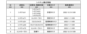
- FIG. 4 is a diagram showing an example of a data structure of system configuration information.
- FIG. 4 is a diagram showing an example of a data structure of control task information.
- FIG. 4 is a diagram showing an example of a data structure of system configuration information.
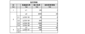
- FIG. 4 is a diagram showing an example of a data structure of load information.
- FIG. 4 is a diagram showing an example of a data structure of control configuration planning information.
- FIG. 4 is a diagram showing an example of a data structure of impact assessment information.
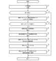
- 4 is a flowchart showing the overall processing by the incident response system.
- 11 is a flowchart showing detailed processing of S5 in FIG. 10;
- FIG. 4 is a diagram showing a display screen of an HMI.
- Figure 1 shows a diagram of the power system and computer components.
- the power system 10 has a plurality of substation equipment 11 and a plurality of switches 12 electrically connected between the substation equipment 11.
- the substation equipment 11 has a transformer 13 and a plurality of switches 14.
- the downstream of the switch 12 is electrically connected to a load L.
- the information on the load L may include the number of consumers W.
- a computer component 20 that controls various facilities included in the power system 10 is connected via communication to the power system 10.
- the computer component 20 has an IT operations layer 21, a supervisory control layer 22, and a field control layer 23.
- the IT operations layer 21, supervisory control layer 22, and field control layer 23 form a hierarchical structure from the top.
- the IT business layer 21 includes a data center (DC in the figure) 24 and an information distribution system 25.
- the data center 24 stores various data.
- the information distribution system 25 may be a workstation.
- the information distribution system 25 will hereinafter also be referred to simply as a component.
- the data center 24 and the information distribution system 25 are communicatively connected to each other via a business network 26.
- the business network 26 may be, for example, a WAN (Wide Area Network).
- the business network 26 is communicatively connected to the external Internet via a firewall (FW in the figure) 27.
- the data center 24 and the information distribution system 25 function as examples of "components".
- the data center 24 and the information distribution system 25 will hereinafter also be referred to simply as components.
- the monitoring and control layer 22 includes, for example, a substation monitoring and control system 28, a plurality of distribution control systems 29, and a firewall network monitor (hereinafter, FW network monitor) 30.
- the substation monitoring and control system 28 and the distribution control system 29 may be control servers (Ctrl servers in the figure).
- the substation monitoring and control system 28 remotely monitors and controls a control controller 35 of the field control layer 23, which will be described later.
- the distribution control system 29 remotely monitors and controls a control controller 36 of the field control layer 23, which will be described later.
- the substation monitoring and control system 28, the plurality of distribution control systems 29, and the FW network monitor 30 are connected to each other for communication via a monitoring and control network 31.
- the FW network monitor 30 is provided between the information distribution system 25 and the monitoring and control network 31.
- the FW network monitor 30 has log collection software and collects communication logs and operation logs of the substation monitoring and control system 28 and the distribution control system 29.
- a firewall (FW in the figure) 32 is provided between multiple distribution control systems 29 in the monitoring and control network 31.
- the substation monitoring and control system 28 and the distribution control system 29 function as examples of "components.”
- the substation monitoring and control system 28 and the distribution control system 29 will also be referred to simply as components.
- the field control layer 23 includes a control controller 35 that is communicatively connected downstream of the substation monitoring control system 28, and a plurality of control controllers (devices) 36 that are communicatively connected downstream of a plurality of power distribution control systems 29.
- the plurality of control controllers 36 are communicatively connected to each other via a field network 37.
- the control controller 35 controls the substation equipment 11.
- the control controller 36 controls the switch 12.
- the control controller 35 and the control controller 36 function as examples of "components.” Hereinafter, the control controller 35 and the control controller 36 will also be simply referred to as components.
- Figure 2 shows the configuration of the computer components.
- the field network 37 is further communicatively connected to a routing network monitor 38.
- the routing network monitor 38 is provided between the field network 37 and the monitoring and control network 31.
- the routing network monitor 38 has log collection software, and collects communication logs and operation logs of the control controller 35 and the control controller 36.
- An HMI (Human Machine Interface) 39 is further connected for communication with the monitoring and control network 31.
- the HMI 39 may be a touch panel operated by a user.
- the incident response system 1 is further connected to the business network 26 for communication.
- the incident response system 1 has log analysis software, and accumulates and analyzes the logs of the components 28, 29, 35, and 36 collected by the FW network monitor 30 and the routing network monitor 38, as well as the log of the component 25.
- the incident response system 1 also has configuration optimization software, and creates an optimal degeneration plan for the power system 10 and the computer component 20.
- Figure 3 shows the software configuration of the computer components.
- the control controller 35 has control logic 35a that controls the substation equipment 11.
- the control controller 36 has control logic 36a that controls the switch 12.
- the routing network monitor 38a which is communicatively connected to the substation monitoring and control system 28, has a status monitoring display unit 40, a control instruction unit 41, and a system information database (hereinafter, DB) 42.
- the status monitoring display unit 40 monitors the status of the control controller 35 and displays the status of the control controller 35 to the user.
- the control instruction unit 41 controls the control controller 35 according to instructions input by the user.
- the system information DB 42 stores various information on the substation equipment 11.
- the substation monitoring and control system 28 has a status monitoring display unit 40, a control instruction unit 41, and a system information DB 42.
- the routing network monitor 38b which is communicatively connected to the power distribution control system 29, has a status monitoring display unit 42, a control instruction unit 43, and a system information DB 44.
- the status monitoring display unit 42 monitors the status of the control controller 36 and displays the status of the control controller 36 to the user.
- the control instruction unit 43 controls the control controller 36 according to instructions input by the user.
- the system information DB 44 stores various information about the switch 12.
- the power distribution control system 29, like the routing network monitor 38b, has a status monitoring display unit 42, a control instruction unit 43, and a system information DB 44.
- the FW network monitor 30 has a log collection and transmission unit 45, a communication management unit (access control unit) 46, and a communication and operation log DB 47.
- the log collection and transmission unit 45 collects communication logs and operation logs of the substation monitoring and control system 28 and the power distribution control system 29, and transmits the collected communication logs and operation logs to the incident response system 1.
- the communication management unit 46 manages communication from the information distribution system 25 to the monitoring and control network 31.
- the communication and operation log 47 stores the communication logs and operation logs of the substation monitoring and control system 28 and the power distribution control system 29 collected by the log collection and transmission unit 45.
- the information distribution system 25 has a system information DB 47, a system information display application 48, and an analysis and optimization application 49.
- the system information DB 47 stores various data on the power system 10.
- the information display application 48 displays the data stored in the system information DB 47 to the user.
- the analysis and optimization application 49 analyzes the data stored in the system information DB 47 and optimizes the analyzed data.
- the incident response system 1 includes a CPU 3 and a memory 4.
- the CPU 4 executes the programs stored in the memory 4, which are described below, to function as a log collection unit 50, an intrusion detection unit 51, a suspicious component extraction unit 52 (an example of an "extraction unit”), a degeneration plan creation unit 53, a power outage evaluation unit 54 (an example of an "evaluation unit”), a recovery plan creation unit 55, and a recovery instruction unit 56.
- the log collection unit 50 collects the communication logs and operation logs of components 28, 29, 35, and 36 collected by the FW network monitor 30 and the routing network monitor 38, and the communication logs and operation logs of components 24 and 25.
- the intrusion detection unit 51 detects victim components in which a security incident has occurred among the components 25, 28, 29, 35, and 36 included in the computer component 20.
- a victim component is a component that is highly likely to have been the subject of unauthorized intrusion.
- a victim component may be detected, for example, by a virus scan.
- the intrusion detection unit 51 extracts victim components based on the operation logs and communication logs of each of the components 28, 29, 35, 36, 24, and 25, and system configuration information as an example of "equipment status".
- the suspect component extraction unit 52 extracts suspect components that have logs from the victim component detected by the intrusion detection unit 51 within a certain period of time.
- the suspect component extraction unit 52 extracts components that have accepted communication and operations from the victim component, i.e., components that are lower than the victim component (hereinafter, suspect lower components).
- the degeneration plan creation unit 53 creates a degeneration plan for degenerating the suspect lower component.
- the degeneration plan is a change plan that degenerates the monitoring and control configuration of the power system 10.
- Degenerate operation may include control transfer, autonomous operation, and shutdown of a component.
- the degenerate planning unit 53 determines whether it is possible to insert (insert) a task of the suspect component into the spare time in the control cycle from among other components that can communicate with the controlled object, and transfers control if the determination result is true. At this time, the degenerate planning unit 53 evaluates the risk that the inserted task due to non-stationary processing will not be executed as the transferable time. Furthermore, when the degenerate planning unit 53 operates the suspect subcomponent autonomously, it evaluates the autonomous operation possible time for the suspect subcomponent that received the operation input from the suspect component from the data freshness required for the operation input (data generated within m minutes is required to operate correctly). Furthermore, when control transfer and autonomous operation are not possible, the degenerate planning unit 53 stops the suspect component and the suspect subcomponent.
- the power outage evaluation unit 54 calculates the power outage load and power outage duration of the suspected sub-component when the suspected sub-component is put into degraded operation based on the degraded plan drawn up by the degraded plan drawing up unit 53.
- the power outage evaluation unit 54 evaluates the power outage impact on the power system 10 based on the calculated power outage load and power outage duration.
- the power outage evaluation unit 54 may determine the degraded plan with the least power outage impact.
- the power outage impact may be an integrated value of the power outage load and power outage duration.
- the recovery plan drawing up unit 55 draws up recovery plans for the damaged component, the suspect component, and the suspected sub-component put into degraded operation.
- the recovery instruction unit 56 instructs recovery work for the damaged component, the suspect component, and the suspected sub-component put into degraded operation based on the recovery plan drawn up by the recovery plan drawing up unit 50.
- Memory 3 has a communication and operation history DB 57 as an example of a "communication operation database", a system configuration information DB 58, a task specification information DB 59, a fault history DB 60, a system configuration DB 61, a demand information DB 62, and a recovery plan DB 63.
- Memory 3 stores programs executed by CPU 3.
- the communication and operation history DB 57 stores the communication logs and operation logs of components 28, 29, 35, and 36 collected by the FW network monitor 30 and the routing network monitor 38, as well as the communication logs and operation logs of components 24 and 25.
- the system configuration information DB 58 stores system configuration information of the various components included in the computer component 20.
- the task specification information DB 59 stores the control tasks executed by the various components included in the computer component 20.
- the fault history DB 60 stores the history of damaged components.
- the system configuration DB 61 stores system configuration information within the power system 10.
- the demand information DB 62 stores information on the load L in the power system 10.
- the recovery plan DB 63 stores recovery plans for damaged components, suspect components, and suspect lower-level components that have been put into degraded operation.
- Figure 4 shows an example of the data structure of system configuration information.
- the system configuration information DB 58 stores system configuration information.
- the system configuration information is a table that stores ID 401, source 402, destination and control target 403, target task 404, and last communication date 405 as item values (column values).
- ID 401 is an identifier that identifies the component.
- Source 402 is the source of the task.
- Destination and control target 403 is the destination of the task (control target).
- Target task 404 indicates the type of task.
- Last communication date 405 is the time of the last communication log.
- Figure 5 shows an example of the data structure of control task information.
- the task specification DB 59 stores control task information.
- the control task information is a table that stores, as item values (column values), an ID 501, a task name 502, an execution component 503, an input source 504, an output destination 505, an execution type 505, an input freshness 507, a control period 508, a CPU time 509, and a last execution time 510.
- ID 501 is an identifier that identifies the task.
- Task name 502 is the name of the task.
- Execution component 503 is the component that executed the task.
- Input source 504 is the input source of the task.
- Output destination 505 is the output destination of the task.
- Execution type 505 is the execution type of the task, which is either periodic stationary or non-stationary.
- Input freshness 507 is the freshness of data required for correct operation.
- Control period 508 is the period for executing the task.
- CPU time 509 is the execution time by the CPU for each task.
- Final execution time 510 is the final execution time of the task.
- Figure 6 shows an example of the data structure of a system configuration DB.
- System configuration DB 61 stores system configuration information.
- the system configuration information is a table that stores ID 601, system line name 602, and connected device 603 as item values (column values).
- ID 601 is an identifier that identifies a system line within power system 10.
- System line name 602 is the name of the system line.
- Connected device 603 is a device that is connected to the system battle.
- Figure 7 shows an example of the data structure of load information.
- the demand information DB stores load information.
- the load information is a table that stores an ID 701, a system line name 702, a maximum load 703, and a number of contracted consumers 704 as item values (column values).
- the ID 701 is an identifier that identifies a system line in the power system 10.
- the system line name 702 is the name of the system line.
- the maximum load 703 is the maximum load on the system line.
- the number of contracted consumers 704 is the number of contracted consumers electrically connected to the system line.
- FIG. 8 shows an example of the data structure of control configuration plan information.
- the recovery plan DB stores control configuration plan information and impact assessment information.
- the control configuration plan information is a table that stores, as item values (column values), ID 801, sender 802, sender and control target 803, target task 804, change type 805, possible continuation time 806, and recovery time 807.
- ID 801 is an identifier that identifies the component.
- Source 802 is the source of the task.
- Destination and controlled object 803 is the destination of the task (controlled object).
- Target task 804 indicates the type of task.
- Change type 805 is either transfer, which transfers a function, autonomous operation, or stop.
- Continuation time 806 is the time during which function transfer or autonomous operation can be continued.
- Recovery time 807 is the time required to recover the component.
- Figure 9 shows an example of the data structure of impact assessment information.
- the impact assessment information is a table that stores the following item values (column values): ID 901, impact scope 902, type 903, maximum load 904, duration 905, power outage duration 906, impact amount 907, and assessment value.
- ID 901 is an identifier that identifies the degeneration plan.
- Impact scope 902 is the scope that is affected by the degeneration plan.
- Type 903 is the type of degeneration plan, which is transfer, autonomous operation, or stop.
- Maximum load 904 is the maximum load amount for each impact scope.
- Duration 905 is the duration of degenerate operation for each impact scope (time during which function can be transferred or autonomous operation is possible).
- Power outage duration 906 is the power outage time required until recovery.
- Impact amount (power outage impact) 907 is the value obtained by integrating the maximum load and power outage time when the duration (time during which function can be transferred or autonomous operation is possible) is shorter than the expected recovery time, and is the impact amount during the power outage for each impact scope.
- Evaluation value 908 is the evaluation value for each degeneration plan.
- Figure 10 is a flowchart showing the overall processing by the incident response system.
- the log collection unit 50 collects the communication logs and operation logs of components 28, 29, 35, and 36 collected by the FW network monitor 30 and the routing network monitor 38, as well as the communication logs and operation logs of components 24 and 25 (S1).
- the intrusion detection unit 51 detects the victim component in which a security incident has occurred among the components 25, 28, 29, 35, and 36 included in the computer component 20, and determines whether an intrusion has been detected (S2).
- the degeneration planning unit 53 extracts a suspect component that has communicated with the victim component (S3).
- the degeneration planning unit 53 determines whether a suspect component has been extracted from all components (S4).
- the degeneration plan creation unit 53 calculates a degeneration plan for stopping the suspect component and performing recovery work, and the power outage evaluation unit 54 calculates the amount of impact (S5).
- the power outage evaluation unit 54 selects the degeneration plan with the least amount of impact (S6).
- the recovery instruction unit 56 stops the damaged component and the suspect component determined to be stopped, and cuts off communication (S7).
- the recovery instruction unit 56 performs recovery work for the stopped components (S8).
- the recovery instruction unit 56 restarts the stopped components and returns to the normal control configuration (S9).
- FIG. 11 is a flowchart showing the detailed processing of S5 in FIG. 10.
- the degeneracy planning unit 53 extracts components that can communicate with the suspected lower-level component (S501). The degeneracy planning unit 53 determines whether there is room to accept control tasks during steady state (S502).
- the degeneracy planning unit 53 extracts the processing time, startup frequency, and interval of the non-stationary task (S503). The degeneracy planning unit 53 determines whether a control task can be accepted in a non-stationary state (S504). If the determination result of S504 is true, the degeneracy planning unit 53 sets the transferable time to a sufficiently large value (S505).
- the degeneration planning unit 53 estimates the next startup time of the non-routine task and sets it as the transferable time (S506).
- the degeneration planning unit 53 determines whether the control task can be accepted in a steady state (S507). If the determination result of S504 is true, the degeneration planning unit 53 stops the suspected lower-level component (S508) and proceeds to S509.
- the degeneration planning unit 53 proceeds to S509.
- the degeneration planning unit 53 calculates the load on the devices controlled by the suspect lower-level component and downstream of the devices from the system configuration.
- the degeneration planning unit 53 calculates the expected power outage time from the difference between the expected recovery time of the suspect component and the time during which it can be handed over or operated autonomously (S510).
- the degeneration planning unit 53 determines the impact of the change in control configuration to be the sum of the load calculated in S509 and the expected power outage time calculated in S510 (S511).
- the degeneration planning unit 53 determines whether the suspected lower-level component is capable of autonomous operation (S512).
- the degeneration planning unit 53 proceeds to S507. If the determination result of S512 is true, the degeneration planning unit 53 obtains the data freshness requirement of the suspicious lower component (S513). The degeneration planning unit 53 sets the data freshness requirement as the autonomous operation possible time (S514).
- Figure 12 shows the HMI display screen.
- the upper left corner of the display screen 120 of the HMI 39 displays a column 121 showing the component where an intrusion was detected and the components that will be affected.
- the lower left corner of the display screen 120 displays a column 122 showing a proposed degeneration plan.
- the lower right corner of the display screen 120 displays a column 123 showing the degenerated simulation and its evaluation (impact of power outage).
- the incident response system 1 includes a memory 4 and a CPU 3.
- the memory 4 includes a communication and operation history database 57 that stores logs of a plurality of components that control the power system 10.
- the CPU 3 includes an intrusion detection unit 51, a suspect component extraction unit 52, a degeneration plan creation unit 53, a power outage evaluation unit 54, and a restoration instruction unit 56.
- the intrusion detection unit 51 detects a victim component in which a security incident has occurred among a plurality of components that control the power system 10.
- the suspect component extraction unit 52 extracts a suspect component that has a log from the victim component.
- the degeneration plan creation unit 53 creates a degeneration plan for degenerating a suspect lower component that is lower than the suspect component.
- the power outage evaluation unit 54 calculates the power outage load and power outage duration of the suspect component when the suspect lower component is degenerated based on the degeneration plan, and evaluates the power outage impact on the power system 10 based on the calculated power outage load and power outage duration.
- the recovery instruction unit 56 instructs the recovery of suspected lower-level components that have been put into degraded operation based on the degraded plan.
- the power outage evaluation unit 54 calculates the integrated value of the power outage load and the power outage duration as the power outage impact. This allows the power outage impact to be calculated with high accuracy using a simple configuration.
- the degeneration plan creation unit 53 extracts, from among the multiple components, a function transfer component capable of transferring the function of the suspected lower component, and creates the degeneration plan when the function of the suspected lower component is transferred to the extracted function transfer component, and the power outage evaluation unit 54 calculates the power outage time as the difference between the expected recovery time of the suspected component and the time during which the function can be transferred to the function transfer component. This makes it possible to minimize the impact of the power outage.
- the degeneration plan creation unit 53 cannot extract a function transfer component, it extracts an autonomous operation component capable of autonomous operation from among the suspected lower-level components, and the power outage evaluation unit 54 calculates the power outage time as the difference between the expected recovery time of the suspected component and the time during which the autonomous operation component is capable of autonomous operation. This makes it possible to operate components capable of autonomous operation as much as possible.
- the power outage evaluation unit 54 evaluates the suspected lower-level component as having stopped functioning. This makes it possible to quickly stop the suspected lower-level component.
- the power outage evaluation unit 54 calculates the load of the suspected lower-level component that will be stopped as the power outage load of the power grid 10. This allows the power outage load to be calculated appropriately.
- the power outage evaluation unit 54 calculates the autonomous operation possible time of the autonomous operation component based on the data freshness required for the operation input from the suspect component to the lower component. This makes it possible to appropriately extract the autonomous operation possible time of the autonomous operation component.
- the suspicious component extraction unit 52 extracts suspicious components based on the operation log, communication log, and equipment status for each of the multiple components. This makes it possible to improve the accuracy of extracting suspicious components.
- the present invention is not limited to the above-described embodiments, but includes various modified examples.
- the above-described embodiments have been described in detail to clearly explain the present invention, and are not necessarily limited to those having all of the configurations described. It is also possible to replace part of the configuration of one embodiment with the configuration of another embodiment, and it is also possible to add the configuration of another embodiment to the configuration of one embodiment. It is also possible to add, delete, or replace part of the configuration of each embodiment with other configurations.
Landscapes
- Engineering & Computer Science (AREA)
- Theoretical Computer Science (AREA)
- Physics & Mathematics (AREA)
- General Engineering & Computer Science (AREA)
- General Physics & Mathematics (AREA)
- Computer Security & Cryptography (AREA)
- Software Systems (AREA)
- Quality & Reliability (AREA)
- Computer Hardware Design (AREA)
- Debugging And Monitoring (AREA)
- Supply And Distribution Of Alternating Current (AREA)
Abstract
電力供給の安定性を向上する。インシデントレスポンスシステム1は、メモリ4とCPU3とを備える。CPUは、プログラムを実行することによって、侵入検知部51、疑いコンポーネント抽出部52、縮退計画立案部53、停電評価部54、および復旧指示部56として機能する。侵入検知部は、セキュリティインシデントが発生した被害コンポーネントを検知する。疑いコンポーネント抽出部は、被害コンポーネントからのログを有する疑いコンポーネントを抽出する。縮退計画立案部は、疑いコンポーネントよりも下位の疑い下位コンポーネントを縮退運転させる縮退計画を立案する。停電評価部は、縮退計画に基づいて疑い下位コンポーネントを縮退運転されたときの疑いコンポーネントの停電負荷量および停電時間を算出し、電力系統の停電影響を評価する。復旧指示部は、縮退計画に基づいて縮退運転させた疑い下位コンポーネントの復旧を指示する。
Description
本発明は、インシデントレスポンスシステムおよび方法に関する。
従来、クローズな環境で運用されていた制御システムは、オープン化、DX(デジタルトランスフォーメーション(Digital Transformation))、およびシステム連携の進展に伴い、オープンなネットワーク環境で利用されることが増えている。
電力システムでも、第5世代移動通信システム(5G)などの広域通信およびクラウドの活用によって、IT(Information Technology)系の業務システムとの連携が可能な場合もある。そのため、ウィルス感染、および外部からの不正な操作などのように、セキュリティインシデントの危険性が高まっている。例えば、オープンな通信環境およびITシステムに起因するセキュリティインシデントにより、停電を含むインフラの障害を引き起こす事例が起きている。
特許文献1には、複数のネットワークインタフェース部のそれぞれに対するアクセス可否情報を記憶し、アクセス可否情報に基づいてネットワークインタフェース部に対するアクセスが許可されているか否かを判断することが記載されている。
特許文献1では、事前に定義されたアクセス可否情報に基づいて、迅速に不正操作を遮断できる。しかし、停電範囲が広がる恐れがあるほか、不正なアプリケーションが正常とは異なる通信経路を使うことを前提としており、正当なアプリケーションおよび通信経路が乗っ取られた際の対象方法や、模擬して侵入された際の対処方法についても述べられていない。
そこで、本発明は、上記課題に鑑みてなされたもので、その目的は、電力供給の安定性を向上する技術を提供することにある。
上記目的を解決するために、本発明は、プログラムが記憶されたメモリと、CPUとを備えたインシデントレスポンスシステムであって、前記メモリには、電力系統を制御する複数のコンポーネントのログとを記憶する通信操作データベースを備え、前記CPUは、前記プログラムを実行することによって、前記複数のコンポーネントのうち、セキュリティインシデントが発生した被害コンポーネントを検知する侵入検知部と、前記通信操作データベースに記憶されたログに基づいて、前記侵入検知部が検知した前記被害コンポーネントからのログを有する疑いコンポーネントを抽出する抽出部と、前記抽出部が抽出した前記疑いコンポーネントよりも下位の疑い下位コンポーネントを縮退運転させる縮退計画を立案する縮退計画立案部と、前記縮退計画立案部が立案した前記縮退計画に基づいて前記疑い下位コンポーネントを縮退運転されたときの前記疑いコンポーネントの停電負荷量および停電時間を算出し、算出した前記停電負荷量および前記停電時間に基づいて前記電力系統の停電影響を評価する評価部と、前記縮退計画に基づいて縮退運転させた前記疑い下位コンポーネントの復旧を指示する復旧指示部として機能する。
本発明によれば、電力供給の安定性を向上することができる。
以下、本発明の実施形態に係るインシデントレスポンスシステムおよび方法の具体例を、図面を参照しつつ説明する。なお、本発明は実施例によって限定されるものではなく、特許請求の範囲によって示される。
図1は、電力系統および計算機コンポーネントの構成図である。
電力系統10は、複数の変電所設備11と、変電所設備11間に電気接続された複数の開閉器12とを有する。変電所設備11は、変圧器13と、複数の開閉器14とを備える。開閉器12の下流は、負荷Lと電気接続されている。負荷Lの情報には、需要家数Wが含まれてよい。
電力系統10には、電力系統10に含まれる各種設備を制御する計算機コンポーネント20が通信接続されている。計算機コンポーネント20は、IT業務層21と、監視制御層22と、フィールド制御層23とを有している。IT業務層21と、監視制御層22と、フィールド制御層23とは、上流から順に階層構造をなしている。
IT業務層21は、データセンタ(図中、DC)24と、情報配信システム25とを備える。データセンタ24は、各種データを記憶する。情報配信システム25は、ワークステーションであってよい。情報配信システム25は、以下、単にコンポーネントとも呼ぶ。データセンタ24と、情報配信システム25とは、業務ネットワーク26を介して相互に通信接続されている。業務ネットワーク26は、例えば、WAN(Wide Area Network)であってよい。業務ネットワーク26は、ファイアウォール(図中、FW)27を介して外部のインターネットに通信接続されている。データセンタ24および情報配信システム25は、「コンポーネント」の一例として機能する。データセンタ24および情報配信システム25は、以下、単にコンポーネントとも呼ぶ。
監視制御層22は、例えば、変電監視制御システム28と、複数の配電制御システム29と、ファイアウォールネットワークモニタ(以下、FWネットワークモニタ)30とを備える。変電監視制御システム28および配電制御システム29は、コントロールサーバ(図中、Ctrlサーバ)であってよい。変電監視制御システム28は、後述するフィールド制御層23の制御コントローラ35を遠隔で監視制御する。配電制御システム29は、後述するフィールド制御層23の制御コントローラ36を遠隔で監視制御する。変電監視制御システム28と、複数の配電制御システム29と、FWネットワークモニタ30とは、監視制御ネットワーク31を介して相互に通信接続されている。FWネットワークモニタ30は、情報配信システム25と、監視制御ネットワーク31との間に設けられている。FWネットワークモニタ30は、ログ収集ソフトウェアを有しており、変電監視制御システム28および配電制御システム29の通信ログおよび操作ログを収集する。監視制御ネットワーク31における複数の配電制御システム29間には、ファイアウォール(図中、FW)32が設けられている。変電監視制御システム28および配電制御システム29は、「コンポーネント」の一例として機能する。変電監視制御システム28および配電制御システム29は、以下、単にコンポーネントとも呼ぶ。
フィールド制御層23は、変電監視制御システム28の下流に通信接続された制御コントローラ35と、複数の配電制御システム29の下流にそれぞれ通信接続された複数の制御コントローラ(デバイス)36とを備える。複数の制御コントローラ36は、フィールドネットワーク37を介して相互に通信接続されている。制御コントローラ35は、変電所設備11を制御する。制御コントローラ36は、開閉器12を制御する。制御コントローラ35および制御コントローラ36は、「コンポーネント」の一例として機能する。制御コントローラ35および制御コントローラ36は、以下、単にコンポーネントとも呼ぶ。
図2は、計算機コンポーネントの構成図である。
フィールドネットワーク37には、さらにルーティングネットワークモニタ38が通信接続されている。ルーティングネットワークモニタ38は、フィールドネットワーク37と、監視制御ネットワーク31との間に設けられている。ルーティングネットワークモニタ38は、ログ収集ソフトウェアを有しており、制御コントローラ35および制御コントローラ36の通信ログおよび操作ログを収集する。
監視制御ネットワーク31には、さらにHMI(Human Machine Interface)39が通信接続されている。HMI39は、ユーザが操作するタッチパネルでよい。
業務ネットワーク26には、さらにインシデントレスポンスシステム1が通信接続される。インシデントレスポンスシステム1は、ログ分析ソフトウェアを有しており、FWネットワークモニタ30およびルーティングネットワークモニタ38が収集したコンポーネント28,29,35,36のログと、コンポーネント25とのログを集積して分析する。インシデントレスポンスシステム1は、さらに構成最適化ソフトウェアを有しており、電力系統10および計算機コンポーネント20の最適な縮退計画を立案する。
図3は、計算機コンポーネントのソフトウェア構成図である。
制御コントローラ35は、変電所設備11を制御する制御ロジック35aを有している。制御コントローラ36は、開閉器12を制御する制御ロジック36aを有している。
変電監視制御システム28に通信接続されたルーティングネットワークモニタ38aは、状態監視表示部40と、制御指示部41と、系統情報データベース(以下、DB)42とを有する。状態監視表示部40は、制御コントローラ35の状態を監視し、その制御コントローラ35の状態をユーザに表示する。制御指示部41は、ユーザが入力した指示に応じて制御コントローラ35を制御する。系統情報DB42は、変電所設備11の各種情報を記憶する。変電監視制御システム28は、ルーティングネットワークモニタ38aと同様に、状態監視表示部40と、制御指示部41と、系統情報DB42とを有する。
配電制御システム29に通信接続されたルーティングネットワークモニタ38bは、状態監視表示部42と、制御指示部43と、系統情報DB44とを有する。状態監視表示部42は、制御コントローラ36の状態を監視し、その制御コントローラ36の状態をユーザに表示する。制御指示部43は、ユーザが入力した指示に応じて制御コントローラ36を制御する。系統情報DB44は、開閉器12の各種情報を記憶する。配電制御システム29は、ルーティングネットワークモニタ38bと同様に、状態監視表示部42と、制御指示部43と、系統情報DB44とを有する。
FWネットワークモニタ30は、ログ収集及び送信部45と、通信管理部(アクセス制御部)46と、通信及び操作ログDB47とを有する。ログ収集及び送信部45は、変電監視制御システム28および配電制御システム29の通信ログおよび操作ログを収集し、収集した通信ログおよび操作ログをインシデントレスポンスシステム1に送信する。通信管理部46は、情報配信システム25から監視制御ネットワーク31への通信を管理する。通信及び操作ログ47は、ログ収集及び送信部45が収集した変電監視制御システム28および配電制御システム29の通信ログおよび操作ログを記憶する。
業務ネットワーク26には、各種の業務システム2と、情報配信システム25と、インシデントレスポンスシステム1が通信接続される。
情報配信システム25は、系統情報DB47と、系統情報表示アプリケーション48と、分析および最適化アプリケーション49とを有する。系統情報DB47は、電力系統10の各種データを記憶する。情報表示アプリケーション48は、系統情報DB47に記憶されたデータをユーザに表示する。分析および最適化アプリケーション49は、系統情報DB47に記憶されたデータを分析し、分析したデータを最適化する。
インシデントレスポンスシステム1は、CPU3と、メモリ4とを備えている。CPU4は、メモリ4に記憶された後述するプログラムを実行することで、ログ収集部50と、侵入検知部51と、「抽出部」の一例としての疑いコンポーネント抽出部52と、縮退計画立案部53と、「評価部」の一例としての停電評価部54と、復旧計画立案部55と、復旧指示部56として機能する。
ログ収集部50は、FWネットワークモニタ30およびルーティングネットワークモニタ38が収集したコンポーネント28,29,35,36の通信ログおよび操作ログと、コンポーネント24,25の通信ログおよび操作ログを収集する。侵入検知部51は、計算機コンポーネント20に含まれるコンポーネント25,28,29,35,36のうち、セキュリティインシデントが発生した被害コンポーネントを検知する。被害コンポーネントとは、不正な侵入の可能性が高いコンポーネントである。被害コンポーネントは、例えばウィルススキャンによって検知してよい。具体的には、侵入検知部51は、コンポーネント28,29,35,36,24,25毎の、操作ログと、通信ログと、「設備状態」の一例としてのシステム構成情報とに基づいて、被害コンポーネントを抽出する。
疑いコンポーネント抽出部52は、侵入検知部51が検知した被害コンポーネントからのログを一定期間内に有する疑いコンポーネントを抽出する。疑いコンポーネント抽出部52は、被害コンポーネントから通信、操作を受け入れていたコンポーネント、即ち被害コンポーネントよりも下位のコンポーネント(以下、疑い下位コンポーネント)を抽出する。縮退計画立案部53は、疑い下位コンポーネントを縮退運転させる縮退計画を立案する。縮退計画は、電力系統10の監視制御構成を縮退させた変更計画である。
縮退運転には、コンポーネントの制御移譲、自律運転および停止が含まれてよい。例えば、縮退計画立案部53は、制御対象に通信可能な他のコンポーネントの中から、制御周期内の余裕時間に疑いコンポーネントのタスクを挿入(差し込み)可能かを判定し、判定結果が真の場合、制御移譲する。このとき、縮退計画立案部53は、非定常処理によって差し込まれたタスクが実行されないリスクを移譲可能時間として評価する。さらに、縮退計画立案部53は、疑い下位コンポーネントを自律運転する場合、疑いコンポーネントから操作入力を受けていた疑い下位コンポーネントについて、操作入力に要求されるデータ鮮度(正しい動作をするためにはm分以内に生成されたデータが必要)から自律運転可能時間を評価する。さらに、縮退計画立案部53は、制御移譲および自律運転が不可能な場合、疑いコンポーネントおよび疑い下位コンポーネントを停止する。
停電評価部54は、縮退計画立案部53が立案した縮退計画に基づいて疑い下位コンポーネントを縮退運転させたときの疑い下位コンポーネントの停電負荷量および停電時間を算出する。停電評価部54は、算出した停電負荷量および停電時間に基づいて電力系統10の停電影響を評価する。停電評価部54は、最も停電影響の少ない縮退計画を決定してよい。停電影響は、停電負荷量と停電時間との積算値であってよい。復旧計画立案部55は、被害コンポーネント、疑いコンポーネントおよび縮退運転させた疑い下位コンポーネントの復旧計画を立案する。復旧指示部56は、復旧計画立案部50が立案した復旧計画に基づいて、被害コンポーネント、疑いコンポーネントおよび縮退運転させた疑い下位コンポーネントの復旧作業を指示する。
メモリ3は、「通信操作データベース」の一例としての通信および操作履歴DB57と、システム構成情報DB58と、タスク仕様情報DB59と、障害履歴DB60と、系統構成DB61と、需要情報DB62と、復旧計画DB63とを有する。メモリ3には、CPU3が実行するプログラムが記憶されている。
通信および操作履歴DB57は、FWネットワークモニタ30およびルーティングネットワークモニタ38が収集したコンポーネント28,29,35,36の通信ログおよび操作ログと、コンポーネント24,25の通信ログおよび操作ログとを記憶する。システム構成情報DB58は、計算機コンポーネント20に含まれる各種コンポーネントのシステム構成情報を記憶する。
タスク仕様情報DB59は、計算機コンポーネント20に含まれる各種コンポーネントで実行された制御タスクを記憶する。障害履歴DB60は、被害コンポーネントの履歴を記憶する。系統構成DB61は、電力系統10内の系統の構成情報を記憶する。需要情報DB62は、電力系統10における負荷Lの情報を記憶する。復旧計画DB63は、被害コンポーネント、疑いコンポーネントおよび縮退運転させた疑い下位コンポーネントの復旧計画を記憶する。
図4は、システム構成情報のデータ構造例を示す図である。
システム構成情報DB58は、システム構成情報を格納する。システム構成情報は、項目値(カラム値)として、ID401と、送信元402と、送信先および制御対象403と、対象タスク404と、最終通信日405とを格納するテーブルである。ID401は、コンポーネントを特定する識別子である。送信元402は、タスクの送信元である。送信先および制御対象403は、タスクの送信先(制御対象)である。対象タスク404は、タスクの種類を示す。最終通信日405は、最終の通信ログの時間である。
図5は、制御タスク情報のデータ構造例を示す図である。
タスク仕様DB59には、制御タスク情報が格納される。制御タスク情報は、項目値(カラム値)として、ID501と、タスク名称502と、実行コンポーネント503と、入力元504と、出力先505と、実行タイプ505と、入力鮮度507と、制御周期508と、CPU時間509と、最終実行時間510とを格納するテーブルである。
ID501は、タスクを特定する識別子である。タスク名称502は、タスクの名称である。実行コンポーネント503は、タスクを実行したコンポーネントである。入力元504は、タスクの入力元である。出力先505は、タスクの出力先である。実行タイプ505は、タスクの実行タイプであり、周期定常または非定常の何れかである。入力鮮度507は、正しい動作をするために要求されるデータの鮮度である。制御周期508は、タスクを実行する周期である。CPU時間509は、タスク毎のCPUによる実行時間である。最終実行時間510は、タスクの最終の実行時間である。
図6は、系統構成DBのデータ構造例を示す図である。
系統構成DB61には、系統構成情報が格納される。系統構成情報は、項目値(カラム値)として、ID601と、系統線名称602と、接続機器603とを格納するテーブルである。ID601は、電力系統10内の系統線を特定する識別子である。系統線名称602は、系統線の名称である。接続機器603は、系統戦に接続されている機器である。
図7は、負荷情報のデータ構造例を示す図である。
需要情報DBには、負荷情報が格納される。負荷情報は、項目値(カラム値)として、ID701と、系統線名称702と、最大負荷703と、契約需要家数704とを格納するテーブルである。ID701は、電力系統10内の系統線を特定する識別子である。系統線名称702は、系統線の名称である。最大負荷703は、系統線における最大の負荷量である。契約需要家数704は、系統線に電気接続される契約需要家の数である。
図8は、制御構成計画情報のデータ構造例を示す図である。
復旧計画DBには、制御構成計画情報および影響評価情報が格納される。制御構成計画情報は、項目値(カラム値)として、ID801と、送信元802と、送信元および制御対象803と、対象タスク804と、変更タイプ805と、継続可能時間806と、復旧時間807とを格納するテーブルである。
ID801は、コンポーネントを特定する識別子である。送信元802は、タスクの送信元である。送信先および制御対象803は、タスクの送信先(制御対象)である。対象タスク804は、タスクの種類を示す。変更タイプ805は、機能を移譲する移譲、自律運転、停止のいずれかである。継続可能時間806は、機能移譲可能時間または自律運転可能時間を継続可能な時間である。復旧時間807は、コンポーネントを復旧するのに要する時間である。
図9は、影響評価情報のデータ構造例を示す図である。
影響評価情報は、項目値(カラム値)として、ID901と、影響範囲902と、タイプ903と、最大負荷904と、持続時間905と、停電時間906と、影響量907、評価値とを格納するテーブルである。
ID901は、縮退計画を特定する識別子である。影響範囲902は、縮退計画が影響する範囲である。タイプ903は、縮退計画のタイプであり、移譲、自律運転または停止である。最大負荷904は、影響範囲毎の最大負荷量である。持続時間905は、影響範囲毎の縮退運転の持続時間(機能移譲可能時間または自律運転可能時間)である。停電時間906は、復旧するまでに要する停電時間である。影響量(停電影響)907は、持続時間(機能移譲可能時間または自律運転可能時間)が復旧見込み時間よりも短い場合に最大負荷と停電時間とを積算した値であり、影響範囲毎の停電中の影響量である。評価値908は、縮退計画毎の評価値である。
図10は、インシデントレスポンスシステムによる全体処理を示すフローチャートである。
まず、ログ収集部50は、FWネットワークモニタ30およびルーティングネットワークモニタ38が収集したコンポーネント28,29,35,36の通信ログおよび操作ログと、コンポーネント24,25の通信ログおよび操作ログを収集する(S1)。
侵入検知部51は、侵入検知部51は、計算機コンポーネント20に含まれるコンポーネント25,28,29,35,36のうち、セキュリティインシデントが発生した被害コンポーネントを検知し、侵入検知の有無を判定する(S2)。
縮退計画立案部53は、S2の判定結果が真の場合、被害コンポーネントと通信送受信を行った疑いコンポーネントを抽出する(S3)。縮退計画立案部53は、全てのコンポーネントの中で疑いコンポーネントを抽出したかを判定する(S4)。
縮退計画立案部53は、S4の判定結果が真の場合、疑いコンポーネントを停止および復旧作業したときの縮退計画を算出し、停電評価部54は、その影響量を算出する(S5)。停電評価部54は、最も影響量が少ない縮退計画を選定する(S6)。復旧指示部56は、被害コンポーネントと、停止と判定された疑いコンポーネントを停止し、通信を遮断する(S7)。
復旧指示部56は、停止したコンポーネントの復旧作業を行う(S8)。復旧指示部56は、停止したコンポーネントを再立ち上げし、通常制御構成に復帰する(S9)。
図11は、図10のS5の詳細処理を示すフローチャートである。
縮退計画立案部53は、疑い下位コンポーネントと通信可能なコンポーネントを抽出する(S501)。縮退計画立案部53は、定常時に制御タスクを受け入れ可能な余裕があるか否かを判定する(S502)。
縮退計画立案部53は、S502の判定結果が真の場合、非定常タスクの処理時間、立ち上げ頻度、間隔を抽出する(S503)。縮退計画立案部53は、非定常時に制御タスクを受け入れ可能かを判定する(S504)。縮退計画立案部53は、S504の判定結果が真の場合、移譲可能時間を十分に大きな値とする(S505)。
縮退計画立案部53は、S504の判定結果が偽の場合、非定常タスクの次回立ち上げ時刻を見積り、移譲可能時間とする(S506)。
縮退計画立案部53は、定常時に制御タスクを受け入れ可能かを判定する(S507)。縮退計画立案部53は、S504の判定結果が真の場合、疑い下位コンポーネントを停止し(S508)、S509に進む。
縮退計画立案部53は、S504の判定結果が偽の場合、S509に進む。S509では、縮退計画立案部53は、系統構成から疑い下位コンポーネントが制御する機器とその下流の負荷量を算出する。縮退計画立案部53は、疑いコンポーネントの復旧見込み時間と、移譲または自律運転可能時間との差分から見込み停電時間を算出する(S510)。縮退計画立案部53は、S509で算出した負荷量と、S510で算出した見込み停電時間の積算を制御構成変更の影響量とする(S511)。
縮退計画立案部53は、S502の判定結果が偽の場合、疑い下位コンポーネントが自律運転可能かを判定する(S512)。
縮退計画立案部53は、S512の判定結果が偽の場合、S507に進む。縮退計画立案部53は、S512の判定結果が真の場合、疑い下位コンポーネントのデータ鮮度欲求を取得する(S513)。縮退計画立案部53は、データ鮮度要求を自律運転可能時間とする(S514)。
図12は、HMIの表示画面を示す図である。
HMI39の表示画面120の左上部には、侵入が検知されたコンポーネントとその影響を受けるコンポーネントとを示す欄121が表示される。表示画面120の左下部には、縮退計画案を示す欄122が表示される。表示画面120の右下部には、縮退片したシミュレーションとその評価(停電影響)の欄123が表示される。
この構成によれば、インシデントレスポンスシステム1は、メモリ4と、CPU3とを備える。メモリ4には、電力系統10を制御する複数のコンポーネントのログを記憶する通信および操作履歴データベース57を備える。CPU3は、侵入検知部51と、疑いコンポーネント抽出部52と、縮退計画立案部53と、停電評価部54と、復旧指示部56と、を備える。侵入検知部51は、電力系統10を制御する複数のコンポーネントのうち、セキュリティインシデントが発生した被害コンポーネントを検知する。疑いコンポーネント抽出部52は、被害コンポーネントからのログを有する疑いコンポーネントを抽出する。縮退計画立案部53は、疑いコンポーネントよりも下位の疑い下位コンポーネントを縮退運転させる縮退計画を立案する。停電評価部54は、縮退計画に基づいて疑い下位コンポーネントを縮退運転されたときの疑いコンポーネントの停電負荷量および停電時間を算出し、算出した停電負荷量および停電時間に基づいて電力系統10の停電影響を評価する。復旧指示部56は、縮退計画に基づいて縮退運転させた疑い下位コンポーネントの復旧を指示する。
これにより、停電影響が最小となる縮退計画を選定することで、電力供給の安定性を向上することができる。
さらに、停電評価部54は、停電負荷量と停電時間との積算値を停電影響として算出する。これにより、簡単な構成で精度の高い停電影響を算出することができる。
さらに、縮退計画立案部53は、複数のコンポーネントのうち、疑い下位コンポーネントの機能移譲を可能な機能移譲コンポーネントを抽出し、抽出した機能移譲コンポーネントに疑い下位コンポーネントの機能を移譲させたときの前記縮退計画を立案し、停電評価部54は、疑いコンポーネントの復旧見込み時間と、機能移譲コンポーネントの機能移譲可能時間との差分を前記停電時間として算出する。これにより、停電影響を最小限に抑制することができる。
さらに、縮退計画立案部53は、機能移譲コンポーネントを抽出できない場合、疑い下位コンポーネントのうち、自律運転が可能な自律運転コンポーネントを抽出し、停電評価部54は、疑いコンポーネントの復旧見込み時間と、自律運転コンポーネントの自律運転可能時間との差分を停電時間として算出する。これにより、自律運転が可能なコンポーネントを可及的に運転させることができる。
さらに、停電評価部54は、縮退計画立案部53が機能移譲コンポーネントおよび自律運転コンポーネントを抽出できない場合、疑い下位コンポーネントを機能停止と評価する。これにより、疑い下位コンポーネントを速やかに停止させることができる。
さらに、停電評価部54は、機能移譲可能時間および自律運転可能時間が復旧見込み時間よりも短い場合、停止する前記疑い下位コンポーネントの負荷量を電力系統10の停電負荷量として算出する。これにより、停電負荷量を適切に算出することができる。
さらに、停電評価部54は、疑いコンポーネントから下位コンポーネントへの操作入力に要求されるデータ鮮度に基づいて、自律運転コンポーネントの自律運転可能時間を算出する。これにより、自律運転コンポーネントの自律運転可能時間を適切に抽出することができる。
さらに、疑いコンポーネント抽出部52は、前記複数のコンポーネント毎の、操作ログと、通信ログと、設備状態とに基づいて、疑いコンポーネントを抽出する。これにより、疑いコンポーネントの抽出精度を高めることができる。
なお、本発明は上記した実施例に限定されるものではなく、様々な変形例が含まれる。例えば、上記した実施例は本発明をわかりやすく説明するために詳細に説明したものであり、必ずしも説明した全ての構成を備えるものに限定されるものではない。また、ある実施例の構成の一部を他の実施例の構成に置き換えことが可能であり、また、ある実施例の構成に他の実施例の構成を加えることも可能である。また、各実施例の構成の一部について、他の構成の追加・削除・置換をすることが可能である。
1…インシデントレスポンスシステム、3…CPU、4…メモリ、10…電力系統、25…情報配信システム、28…変電監視制御システム、29…配電制御システム、35…制御コントローラ、36…制御コントローラ、51…侵入検知部、52…疑いコンポーネント抽出部、53…縮退計画立案部、54…停電評価部、56…復旧指示部、57…通信および操作データベース
Claims (9)
- プログラムが記憶されたメモリと、CPUとを備えたインシデントレスポンスシステムであって、
前記メモリには、電力系統を制御する複数のコンポーネントのログを記憶する通信操作データベースを備え、
前記CPUは、前記プログラムを実行することによって、
前記複数のコンポーネントのうち、セキュリティインシデントが発生した被害コンポーネントを検知する侵入検知部と、
前記通信操作データベースに記憶されたログに基づいて、前記侵入検知部が検知した前記被害コンポーネントからのログを有する疑いコンポーネントを抽出する抽出部と、
前記抽出部が抽出した前記疑いコンポーネントよりも下位の疑い下位コンポーネントを縮退運転させる縮退計画を立案する縮退計画立案部と、
前記縮退計画立案部が立案した前記縮退計画に基づいて前記疑い下位コンポーネントを縮退運転されたときの前記疑いコンポーネントの停電負荷量および停電時間を算出し、算出した前記停電負荷量および前記停電時間に基づいて前記電力系統の停電影響を評価する評価部と、
前記縮退計画に基づいて縮退運転させた前記疑い下位コンポーネントの復旧を指示する復旧指示部と、として機能するインシデントレスポンスシステム。 - 前記評価部は、前記停電負荷量と前記停電時間との積算値を前記停電影響として算出する、
請求項1に記載のインシデントレスポンスシステム。 - 前記縮退計画立案部は、前記複数のコンポーネントのうち、前記疑い下位コンポーネントの機能移譲を可能な機能移譲コンポーネントを抽出し、抽出した機能移譲コンポーネントに前記疑い下位コンポーネントの機能を移譲させたときの前記縮退計画を立案し、
前記評価部は、前記疑いコンポーネントの復旧見込み時間と、前記機能移譲コンポーネントの機能移譲可能時間との差分を前記停電時間として算出する、
請求項2に記載のインシデントレスポンスシステム。 - 前記縮退計画立案部は、前記機能移譲コンポーネントを抽出できない場合、前記疑い下位コンポーネントのうち、自律運転が可能な自律運転コンポーネントを抽出し、
前記評価部は、前記疑いコンポーネントの復旧見込み時間と、前記自律運転コンポーネントの自律運転可能時間との差分を前記停電時間として算出する、
請求項3に記載のインシデントレスポンスシステム。 - 前記評価部は、前記縮退計画立案部が前記機能移譲コンポーネントおよび前記自律運転コンポーネントを抽出できない場合、前記疑い下位コンポーネントを機能停止と評価する、
請求項4に記載のインシデントレスポンスシステム。 - 前記評価部は、前記機能移譲可能時間および前記自律運転可能時間が前記復旧見込み時間よりも短い場合、停止する前記疑い下位コンポーネントの負荷量を前記電力系統の停電負荷量として算出する、
請求項5に記載のインシデントレスポンスシステム。 - 前記評価部は、前記疑いコンポーネントから前記下位コンポーネントへの操作入力に要求されるデータ鮮度に基づいて、前記自律運転コンポーネントの前記自律運転可能時間を算出する、
請求項6に記載のインシデントレスポンスシステム。 - 前記抽出部は、前記複数のコンポーネント毎の、操作ログと、通信ログと、設備状態とに基づいて、前記疑いコンポーネントを抽出する、
請求項1に記載のインシデントレスポンスシステム。 - 電力系統を制御する複数のコンポーネントのうち、セキュリティインシデントが発生した被害コンポーネントを検知するステップと、
前記被害コンポーネントからのログを有する疑いコンポーネントを抽出するステップと、
前記疑いコンポーネントよりも下位の疑い下位コンポーネントを縮退運転させる縮退計画を立案するステップと、
前記縮退計画に基づいて、前記疑い下位コンポーネントを縮退運転されたときの前記疑いコンポーネントの停電負荷量および停電時間を算出し、算出した前記停電負荷量および前記停電時間の積算値を前記電力系統の停電影響として評価するステップと、
前記縮退計画に基づいて縮退運転させた前記疑い下位コンポーネントの復旧を指示するステップと、を有するインシデントレスポンス方法。
Applications Claiming Priority (2)
| Application Number | Priority Date | Filing Date | Title |
|---|---|---|---|
| JP2023111745A JP2025009033A (ja) | 2023-07-06 | 2023-07-06 | インシデントレスポンスシステムおよび方法 |
| JP2023-111745 | 2023-07-06 |
Publications (1)
| Publication Number | Publication Date |
|---|---|
| WO2025009409A1 true WO2025009409A1 (ja) | 2025-01-09 |
Family
ID=94171816
Family Applications (1)
| Application Number | Title | Priority Date | Filing Date |
|---|---|---|---|
| PCT/JP2024/022416 Ceased WO2025009409A1 (ja) | 2023-07-06 | 2024-06-20 | インシデントレスポンスシステムおよび方法 |
Country Status (2)
| Country | Link |
|---|---|
| JP (1) | JP2025009033A (ja) |
| WO (1) | WO2025009409A1 (ja) |
Citations (3)
| Publication number | Priority date | Publication date | Assignee | Title |
|---|---|---|---|---|
| JP2013533531A (ja) * | 2010-05-20 | 2013-08-22 | アクセンチュア グローバル サービスィズ リミテッド | 悪意のある攻撃の検出および分析 |
| WO2017187520A1 (ja) * | 2016-04-26 | 2017-11-02 | 三菱電機株式会社 | 侵入検知装置、侵入検知方法及び侵入検知プログラム |
| JP2018170006A (ja) * | 2017-03-08 | 2018-11-01 | ゼネラル・エレクトリック・カンパニイ | 電力グリッドにおけるサイバー脅威を検出する汎用フレームワーク |
-
2023
- 2023-07-06 JP JP2023111745A patent/JP2025009033A/ja active Pending
-
2024
- 2024-06-20 WO PCT/JP2024/022416 patent/WO2025009409A1/ja not_active Ceased
Patent Citations (3)
| Publication number | Priority date | Publication date | Assignee | Title |
|---|---|---|---|---|
| JP2013533531A (ja) * | 2010-05-20 | 2013-08-22 | アクセンチュア グローバル サービスィズ リミテッド | 悪意のある攻撃の検出および分析 |
| WO2017187520A1 (ja) * | 2016-04-26 | 2017-11-02 | 三菱電機株式会社 | 侵入検知装置、侵入検知方法及び侵入検知プログラム |
| JP2018170006A (ja) * | 2017-03-08 | 2018-11-01 | ゼネラル・エレクトリック・カンパニイ | 電力グリッドにおけるサイバー脅威を検出する汎用フレームワーク |
Also Published As
| Publication number | Publication date |
|---|---|
| JP2025009033A (ja) | 2025-01-20 |
Similar Documents
| Publication | Publication Date | Title |
|---|---|---|
| EP3660612B1 (en) | Method and system for elimination of fault conditions in a technical installation | |
| CN106462137B (zh) | 用于保障工业控制系统的系统和方法 | |
| JP6961740B2 (ja) | 産業用コントローラのデータ完全性を保証するためのaiの使用 | |
| KR102231648B1 (ko) | 소방시설의 점검 이력 정보 관리 방법, 장치 및 컴퓨터-판독가능 기록 매체 | |
| KR101300743B1 (ko) | 전 이중화 방식 직접디지털제어기를 이용한 빌딩설비자동제어 시스템 및 그 제어 방법 | |
| US20220131748A1 (en) | Virtual supervisory control and data acquisition (scada) automation controller | |
| WO2018198733A1 (ja) | セキュリティ監視システム及びセキュリティ監視方法 | |
| EP3571820B1 (en) | Management of federated systems | |
| CN120110893A (zh) | 一种基于数字孪生技术的网络运维方法及系统 | |
| Venkataramanan et al. | Enhancing microgrid resiliency against cyber vulnerabilities | |
| KR20160087280A (ko) | 스마트 워터 그리드 기반 통합 운영 서비스 제공 방법 및 시스템 | |
| Sasaki et al. | Fallback and recovery control system of industrial control system for cybersecurity | |
| US20170244252A1 (en) | Autonomous Operational Platform for Micro-Grid Energy Management | |
| JP2025009033A (ja) | インシデントレスポンスシステムおよび方法 | |
| CN105849699B (zh) | 控制数据中心架构设备的方法 | |
| JP5503321B2 (ja) | 運用管理方法、プログラムおよび運用管理システム | |
| JP6377537B2 (ja) | 電力系統監視装置、電力系統監視方法及び電力系統監視プログラム | |
| Lazarova-Molnar et al. | Reliability analysis of cyber-physical systems | |
| US10878690B2 (en) | Unified status and alarm management for operations, monitoring, and maintenance of legacy and modern control systems from common user interface | |
| GB2558902A (en) | Management of federated systems | |
| CN115660891A (zh) | 一种基于动态本体业务模型实现的预警事件的对象关系关联方法 | |
| KR20210078311A (ko) | 머신러닝 알고리즘 기반 스마트 빌딩 IoT 기기 간 데이터 관리 | |
| Gupta et al. | Why Dealing with Electrical Faults for Smart Microgrid is not Enough? | |
| Chockalingam | Using Decision Trees to Select Effective Response Strategies in Industrial Control Systems | |
| US20210263819A1 (en) | Apparatuses, methods, and computer program products for industrial automation control system configuration error processing |
Legal Events
| Date | Code | Title | Description |
|---|---|---|---|
| 121 | Ep: the epo has been informed by wipo that ep was designated in this application |
Ref document number: 24835922 Country of ref document: EP Kind code of ref document: A1 |
|
| NENP | Non-entry into the national phase |
Ref country code: DE |