WO2025009352A1 - 車両内装システム - Google Patents
車両内装システム Download PDFInfo
- Publication number
- WO2025009352A1 WO2025009352A1 PCT/JP2024/021537 JP2024021537W WO2025009352A1 WO 2025009352 A1 WO2025009352 A1 WO 2025009352A1 JP 2024021537 W JP2024021537 W JP 2024021537W WO 2025009352 A1 WO2025009352 A1 WO 2025009352A1
- Authority
- WO
- WIPO (PCT)
- Prior art keywords
- sensor
- control unit
- vehicle
- message
- seat
- Prior art date
- Legal status (The legal status is an assumption and is not a legal conclusion. Google has not performed a legal analysis and makes no representation as to the accuracy of the status listed.)
- Ceased
Links
Images














Classifications
-
- B—PERFORMING OPERATIONS; TRANSPORTING
- B60—VEHICLES IN GENERAL
- B60N—SEATS SPECIALLY ADAPTED FOR VEHICLES; VEHICLE PASSENGER ACCOMMODATION NOT OTHERWISE PROVIDED FOR
- B60N2/00—Seats specially adapted for vehicles; Arrangement or mounting of seats in vehicles
- B60N2/24—Seats specially adapted for vehicles; Arrangement or mounting of seats in vehicles for particular purposes or particular vehicles
- B60N2/42—Seats specially adapted for vehicles; Arrangement or mounting of seats in vehicles for particular purposes or particular vehicles the seat constructed to protect the occupant from the effect of abnormal g-forces, e.g. crash or safety seats
-
- B—PERFORMING OPERATIONS; TRANSPORTING
- B60—VEHICLES IN GENERAL
- B60N—SEATS SPECIALLY ADAPTED FOR VEHICLES; VEHICLE PASSENGER ACCOMMODATION NOT OTHERWISE PROVIDED FOR
- B60N2/00—Seats specially adapted for vehicles; Arrangement or mounting of seats in vehicles
- B60N2/90—Details or parts not otherwise provided for
Definitions
- This disclosure relates to a vehicle interior system that includes interior components and a control unit.
- a system in which a movable member such as a seat back moves when the user operates a sensor installed in a power seat (see Patent Publication No. 551228).
- the movable parts simply move in response to the user's operation of the sensor, so it lacks entertainment value.
- a vehicle interior system includes an interior component to be placed inside a vehicle, an electric device that causes a portion of the surface of the interior component to move back and forth, a first sensor to which information is input by a user, a display unit, and a control unit.
- the control unit is capable of displaying a character on the display unit, and moves the character based on information from the first sensor, and operates the electrically-driven device in a manner corresponding to the movement of the character.
- the first sensor may also be a pressure sensor, and the control unit may move the character and the electric device based on the pressure value from the pressure sensor.
- the first sensor may also be a tactile sensor that detects displacement in three-dimensional directions, and the control unit may move the character and the electric device based on the direction of displacement obtained from the tactile sensor.
- the control unit may also calculate the degree of intimacy between the user and the character, and change the behavior of at least one of the character and the electric device depending on the degree of intimacy.
- the control unit may also increase the degree of intimacy if the time interval between when information is input to the first sensor and when the next information is input to the first sensor is less than or equal to a predetermined value.
- the control unit may also increase the degree of intimacy when the number of times information is input to the first sensor per predetermined time period is equal to or greater than a predetermined number.
- the interior member may be a seat, and the first sensor may be positioned in a position that avoids the seating surface of the seat.
- the vehicle interior system may further include a switch for switching the control unit between a first mode in which the character and the electric device are not linked, and a second mode in which the electric device is operated in a manner corresponding to the character's movement.
- control unit may end the second mode and execute the first mode.
- the second mode is terminated, making the user aware of something unusual and enabling the user to, for example, assume a posture in preparation for a collision.
- a vehicle system capable of transmitting a message from a first vehicle to a second vehicle is known in the art, which displays multiple messages on a screen and allows a user to select one message from the multiple messages (see JP 2007-148524 A).
- a vehicle system in one aspect is a system capable of transmitting a message from a first vehicle to a second vehicle.
- the first vehicle includes at least one sensor and a first controller.
- the sensor is provided in an interior member excluding the screen and an operation unit for operating an object on the screen.
- the sensor detects contact with a user.
- the first control unit selects one message from a plurality of pre-stored messages based on information obtained from the sensor that changes depending on how the user touches the interior member, and transmits the selected message to the second vehicle.
- the second vehicle may also include a display unit capable of displaying a character and a second control unit, and the second control unit may move the character in a manner corresponding to the message received from the first vehicle.
- the character displayed on the display unit of the second vehicle moves in a way that corresponds to the message, making the experience more entertaining.
- the interior material may also have a cushion.
- the interior member may also be a decorative item attached to the first vehicle.
- the second vehicle may also include a seat, an electric device provided in the seat, and a second control unit, and the second control unit may operate the electric device in accordance with an operation corresponding to the message received from the first vehicle.
- the electric device operates in response to the message, which can enhance entertainment value, for example.
- the electric device may also be a vibration device that vibrates the seating surface of the seat, and the second control unit may operate the vibration device with a vibration pattern corresponding to the message obtained from the first vehicle.
- the senor may be a pressure sensor
- the first control unit may select a message based on a pressure value obtained from the pressure sensor.
- the interior component may also have lighting, and the first control unit may turn on the lighting in a lighting pattern corresponding to the selected message.
- the first vehicle may also include a first sensor and a second sensor disposed at a different position from the first sensor, and the first control unit may select a first message based on a signal from the first sensor, and select a second message different from the first message based on a signal from the second sensor.
- the second vehicle may also include a first electric device arranged at a position corresponding to a first sensor provided on the first vehicle, a second electric device arranged at a position corresponding to a second sensor provided on the first vehicle, and a second control unit, and the second control unit may operate the first electric device when it receives a first message from the first vehicle, and operate the second electric device when it receives a second message from the first vehicle.
- a first electric device located at a position corresponding to the first sensor in the second vehicle is activated, allowing the user of the second vehicle to know the location that the user touched in the first vehicle.
- the interior member may be a seat, and the sensor may be positioned to avoid the seating surface of the seat.
- the second vehicle may also include a seat, a vibration device that vibrates the seating surface of the seat, and a second control unit, and when the first control unit predicts a collision between the first vehicle and the second vehicle based on information from a collision detection unit provided in the first vehicle, the first control unit may transmit a collision message to the second vehicle forecasting the vehicle collision, and the second control unit may operate the vibration device with a vibration pattern corresponding to the collision message obtained from the first vehicle.
- the user of the second vehicle can be informed of a vehicle collision predicted by the first vehicle.
- FIG. 1 is a diagram showing a vehicle interior system according to a first embodiment.
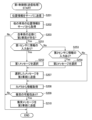
- FIG. 4 is a flowchart showing the operation of a control unit.
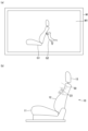
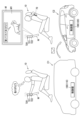
- FIG. 1A shows an image of a cat relaxing, and FIG. 1B shows the state of the seat at that time.
- FIG. 1A shows an image of a cat doing a cat punch, and
- FIG. 1B shows the state of the sheet at that time.
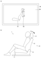
- FIG. 1A shows an image of a cat hanging from a seat back, and FIG. 1B shows the state of the seat at that time.
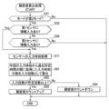
- 13 is a flowchart showing an intimacy calculation process performed by a control unit according to the second embodiment.
- 10 is a flowchart showing an operation of a control unit according to the second embodiment.
- FIG. 13 is a flowchart showing an intimacy degree calculation process performed by a control unit according to the third embodiment. 13 is a flowchart showing an intimacy calculation process performed by a control unit according to the fourth embodiment.
- FIG. 13 is a perspective view showing a modified example of the seat and the sensor position.
- FIG. 13 is a diagram showing a modified example of the sensor position.
- FIG. 13 is a diagram showing a modified example of the sensor position.
- FIG. 13 is a diagram showing a modified example of the sensor position.
- 10 is a flowchart showing a modified example of the operation of the control unit.
- FIG. 13 is a diagram showing a tactile sensor as a modified example of the sensor. 13 is a flowchart showing the operation of a control unit when a tactile sensor is used.
- FIG. 13 is a perspective view showing a modified example of the seat and the sensor position.
- FIG. 13 is a diagram showing a modified example of the sensor position.
- FIG. 13 is a diagram showing a modified
- FIG. 13 is a diagram showing a vehicle system according to a fifth embodiment. This is a rear view of the structure around the dashboard.
- FIG. 13 is a diagram showing an image corresponding to a message of gratitude.
- FIG. 13 is a diagram showing an image corresponding to an apology message.
- FIG. 13 shows an image corresponding to a lane change message.
- 6 is a flowchart showing an operation of a first control unit.
- 10 is a flowchart showing an operation of a second control unit.
- FIG. 11 is a diagram showing the state inside each vehicle when a message is transmitted.
- FIG. 13 is a diagram showing a vehicle system according to a sixth embodiment.
- 13 is a flowchart showing an operation of a first control unit according to the sixth embodiment.
- 13 is a flowchart showing the operation of a second control unit according to the sixth embodiment.
- FIG. 11 is a diagram showing the state inside each vehicle when a message is transmitted.
- the vehicle interior system 1 includes a seat 10 as an example of an interior member, a monitor M as an example of a display unit, and a control unit 100.
- the seat 10 and the monitor M are disposed in a position facing the interior of the vehicle, more specifically, the passenger compartment.
- the seat 10 is a driver's seat or a passenger seat.
- the seat 10 includes a seat cushion 11, a seat back 12, and a headrest 13.
- the seat cushion 11, the seat back 12, and the headrest 13 each constitute a seat body having a seating surface F.
- the seating surface F is a surface that comes into contact with a user seated on the seat 10 and supports the user.
- the seat cushion 11, seat back 12, and headrest 13 each have a metal frame that forms the framework, a pad that covers the frame, and a skin that covers the pad.
- the pad is made of urethane foam or the like.
- the skin is made of synthetic leather, fabric, or the like.
- the seat cushion 11 has a base portion 11A located in the left-right center, and overhanging portions 11B located on both the left and right outer sides of the base portion 11A.
- the base portion 11A has a seating surface F that contacts and supports the user's buttocks and thighs from below.
- the overhanging portions 11B overhang from the seating surface F of the base portion 11A towards the user to support the sides of the user's thighs and buttocks.
- the seat back 12 has a base portion 12A located in the left-right center and overhanging portions 12B located on both the left and right outer sides of the base portion 12A.
- the base portion 12A has a seating surface F that comes into contact with the user's back and supports the back from behind.
- the overhanging portions 12B overhang toward the user from the seating surface F of the base portion 12A to support the sides of the user's upper body.
- the seat 10 further includes an electric reclining mechanism 21 , a plurality of vibration devices 23 , an electric sliding mechanism 30 , two first sensors 41 , two second sensors 42 , and a plurality of speakers 50 .
- the electric reclining mechanism 21 is a mechanism for tilting the seat back 12.
- the electric reclining mechanism 21 includes a motor that is operated when electricity is applied.
- the vibration device 23 is an electric device that vibrates when electricity is passed through it, causing only a portion of the surface of the seat 10 to move back and forth.
- Multiple vibration devices 23, for example, four, are provided on the base portion 12A of the seat back 12.
- the vibration devices 23 are embedded, for example, in a pad.
- the electric slide mechanism 30 is a mechanism that slides the seat 10 in the front-rear direction.
- the seat 10 is supported on a slide rail (not shown) so that it can move in the front-rear direction.
- the electric slide mechanism 30 is equipped with a motor that is activated by the passage of electricity.
- the first sensor 41 and the second sensor 42 are sensors into which information is input by the user.
- the first sensor 41 and the second sensor 42 are pressure sensors that detect pressure from the user.
- the first sensor 41 and the second sensor 42 are provided at positions that avoid the seating surface F, i.e., at positions away from the seating surface F. More specifically, the first sensor 41 is provided on each of the left and right protruding portions 11B of the seat cushion 11.
- the second sensor 42 is disposed at a different position from the first sensor 41. More specifically, the second sensor 42 is provided on each of the left and right sides of the headrest 13. The first sensor 41 and the second sensor 42 are each located between the skin and the pad.
- the speaker 50 is a device that generates sound when electricity is applied.
- One speaker 50 is provided on each of the left and right sides of the upper part of the seat back 12.
- One speaker 50 is provided on each of the left and right sides of the headrest 13.
- the speaker 50 is embedded in a pad, for example.
- the seat 10 further includes a reclining switch 61, a slide switch 62, and a mode change switch 63.
- the reclining switch 61 is an operating unit for operating the electric reclining mechanism 21.
- the reclining switch 61 can be tilted, for example, in the forward and backward directions.
- When the reclining switch 61 is tilted forward it outputs a forward tilt command to the control unit 100 for tilting the seat back 12 forward.
- When the reclining switch 61 is tilted rearward it outputs a rearward tilt command to the control unit 100 for tilting the seat back 12 rearward.
- the slide switch 62 is an operating unit for operating the electric slide mechanism 30.
- the slide switch 62 can slide, for example, in the forward and backward directions.
- the mode change switch 63 is a switch for changing the mode of the control unit 100 between a first mode and a second mode.
- the first mode is a mode forbidding the linked processing described below.
- the second mode is a mode for permitting the linked processing.
- the mode change switch 63 is, for example, a push button type switch. The mode change switch 63 alternates between an ON state and an OFF state each time it is pressed by the user.
- the control unit 100 is configured to include, for example, a CPU, RAM, ROM, input/output circuits, etc.
- the control unit 100 may be provided in the seat 10, or may be provided in a member other than the seat 10.
- the control unit 100 is connected to the monitor M, various switches (61-63), the electric reclining mechanism 21, each vibration device 23, the electric sliding mechanism 30, each first sensor 41, each second sensor 42, and each speaker 50.
- the control unit 100 is capable of individually activating each vibration device 23 and each speaker 50.
- the control unit 100 has a function of displaying a sheet image G1, which is an image of a sheet, and a cat image G2, which is an image of a cat as an example of a character, on the screen M1 of the monitor M.
- the control unit 100 has a function of executing a linkage process that moves the cat image G2 based on information from the first sensor 41 or the second sensor 42, specifically the pressure value, and activates the vibration device 23 with a movement corresponding to the movement of the cat image G2.
- the control unit 100 displays on the screen M1 a first image of a cat relaxing on a seat, as shown in FIG. 3(a).
- the first image may be a still image or a video.
- the cat's back may move up and down in time with its breathing.
- control unit 100 When the control unit 100 displays the first image on the screen M1, it outputs the sound of a cat making a whining noise or a purring sound from the speaker 50. If the seat 10 is provided with air cells that expand and contract with air, the control unit 100 may expand and contract the air cells in accordance with the cat's breathing to cause a part of the seating surface F to move back and forth.
- the control unit 100 displays on the screen M1 a second image of a cat hitting the seat back with its front paws (hereinafter also referred to as a "cat punch") as shown in FIG. 4(a).
- the second image is a video.
- control unit 100 When the control unit 100 displays the second image on the screen M1, it vibrates the vibration device 23 in synchronization with the timing when the cat's front paws touch the seat back, and outputs the cat's angry voice from the speaker 50. Note that there may be one or more vibration devices 23 that are vibrated.
- the control unit 100 displays on the screen M1 a third image, as shown in FIG. 5(a), in which a cat is hanging from the seat back and the seat back gradually tilts backward.
- the third image is a video.
- control unit 100 When the control unit 100 displays the third image on the screen M1, the control unit 100 causes the actual seat back 12 to rotate backwards using the electric reclining mechanism 21 in accordance with the movement of the seat back on the screen M1. In other words, the control unit 100 causes the actual seat back 12 to rotate backwards using the electric reclining mechanism 21 in accordance with the movement of the cat that moves with the seat back on the screen M1.
- the control unit 100 When the mode is the first mode described above, the control unit 100 does not execute the linking process, thereby not linking the cat on the screen M1 with the vibration device 23.
- the control unit 100 executes the linking process, thereby activating the vibration device 23 with a movement corresponding to the cat punch of the cat on the screen M1.
- control unit 100 repeatedly executes the process shown in Fig. 2.
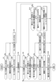
- the control unit 100 first determines whether the mode change switch 63 is ON (S1). If it is determined in step S1 that the mode change switch 63 is not ON (No), the control unit 100 sets the mode to the first mode (S2) and ends this process.
- step S1 If it is determined in step S1 that the mode change switch 63 is ON (Yes), the control unit 100 switches the mode to the second mode (S3) and displays a home screen on the screen M1 (S4).
- the home screen may be any screen.
- the home screen may be a screen on which characters indicating the title of an application program in which a cat performs various actions are displayed.
- step S4 the control unit 100 determines whether the mode change switch 63 is ON (S5). If it is determined in step S5 that the mode change switch 63 is not ON (No), the control unit 100 ends this process.
- step S5 If it is determined in step S5 that the mode changeover switch 63 is ON (Yes), the control unit 100 determines whether the first pressure value acquired by the first sensor 41 is equal to or greater than the first threshold value TH1 (S6). If it is determined in step S6 that the first pressure value is equal to or greater than the first threshold value TH1 (Yes), the control unit 100 determines whether the first pressure value is equal to or greater than the second threshold value TH2 (S7).
- step S7 If it is determined in step S7 that the first pressure value is equal to or greater than the second threshold value TH2 (Yes), the control unit 100 displays a video of the cat punching on the screen M1 (S8). After step S8, the control unit 100 activates the vibration device 23 in time with the cat's cat punching motion (S9).
- step S9 the control unit 100 outputs the cat's angry voice from the speaker 50 (S10) and ends this process.
- step S10 may be performed before step S9 or simultaneously with step S9.
- step S7 If it is determined in step S7 that the first pressure value is not equal to or greater than the second threshold value TH2 (No), the control unit 100 displays an image of a cat relaxing on the screen M1 (S11). After step S11, the control unit 100 outputs the cat's whiny voice from the speaker 50 (S12) and ends this process.
- step S6 determines whether the first pressure value is not equal to or greater than the first threshold value TH1 (No). If it is determined in step S13 that the second pressure value is not equal to or greater than the third threshold value TH3 (No), the control unit 100 returns to the processing of step S5.
- step S13 If it is determined in step S13 that the second pressure value is equal to or greater than the third threshold value TH3 (Yes), the control unit 100 displays on the screen M1 a video of a cat hanging from the seat back, which gradually rotates backwards (S14). After step S14, the control unit 100 operates the electric reclining mechanism 21 in accordance with the movement of the seat back on the screen M1, thereby tilting the actual seat back 12 backwards (S15), and then ends this process.
- control unit 100 When a user sits on the seat 10 shown in FIG. 1 and turns on the mode changeover switch 63, the control unit 100 displays the home screen on the monitor M (S1: Yes ⁇ S3, S4).
- the control unit 100 displays an image of a cat relaxing on the monitor M as shown in FIG. 3(a) and outputs the cat'shieling voice from the speaker 50 (S5: No ⁇ S6: Yes ⁇ S7: No ⁇ S11, S12).
- the control unit 100 will display a video of the cat punching on the monitor M as shown in FIG. 4(a), activate the vibration device 23 in time with the cat punch, and output the cat's angry voice from the speaker 50 (S5: No ⁇ S6: Yes ⁇ S7: Yes ⁇ S8 to S10).
- the control unit 100 will display a video of a cat hanging from the seat back on the monitor M, as shown in FIG. 5(a), and will operate the electric reclining mechanism 21 to tilt the actual seat back 12 backward (S5: No ⁇ S6: No ⁇ S13: Yes ⁇ S14, S15).
- step S10 After executing the process of step S10, step S12 or step S15, the control unit 100 returns the display on the monitor M to the home screen (S1: Yes ⁇ S3 ⁇ S4).
- the control unit 100 changes the mode to the first mode (S5: No ⁇ S1: No ⁇ S2).
- the mode change switch 63 When the mode change switch 63 is switched from ON to OFF, the control unit 100 erases the second mode image that was displayed on the screen M1.
- the control unit 100 moves the cat on the screen M1 and activates the vibration device 23 with movements corresponding to the cat's movements, allowing the user to feel the presence of the cat through the seat 10, thereby enhancing entertainment value.
- the cat on screen M1 behaves differently when the first sensor 41 is operated and when the second sensor 42 is operated, which enhances entertainment value.
- the control unit 100 has a function of executing the intimacy calculation process shown in FIG. 6.
- the intimacy calculation process is a process for calculating the intimacy between the user and the cat on the screen M1.
- the control unit 100 first determines whether the mode is the second mode (S31). If it is determined in step S31 that the mode is not the second mode (No), the control unit 100 ends this process.
- step S31 determines whether or not a pressure equal to or greater than the first threshold value TH1 has been input to the first sensor 41 (S32). If it is determined in step S32 that a pressure equal to or greater than the first threshold value TH1 has been input to the first sensor 41 (Yes), the control unit 100 calculates the time during which a pressure equal to or greater than the first threshold value TH1 has been input to the first sensor 41 (S33).
- step S32 determines whether or not a pressure equal to or greater than the first threshold value TH1 has not been input to the first sensor 41 (No)
- the control unit 100 determines whether or not a pressure equal to or greater than the third threshold value TH3 has been input to the second sensor 42 (S36). If it is determined in step S36 that a pressure equal to or greater than the third threshold value TH3 has been input to the second sensor 42 (Yes), the control unit 100 calculates the time during which a pressure equal to or greater than the third threshold value TH3 has been input to the second sensor 42 (S37).
- control unit 100 calculates the cumulative value of the time that pressure is input to each sensor (41, 42) (S34). After step S34, the control unit 100 calculates the degree of intimacy so that the greater the cumulative value, the higher the degree of intimacy (S35), and ends this process.
- control unit 100 changes the behavior of the cat on the screen M1 and the behavior of the vibration device 23 according to the degree of intimacy.
- the control unit 100 according to the second embodiment executes the process shown in FIG. 7.
- the process shown in FIG. 7 replaces steps S8 to S9, S11, and S12 in the process shown in FIG. 2 with new steps S51 to S55.
- control unit 100 determines in step S7 that the first pressure value is equal to or greater than the second threshold value TH2 (Yes), it displays a video of the cat giving cat punches on the screen M1 in a pattern according to the intimacy level (S51). For example, the control unit 100 reduces the number of cat punches as the intimacy level increases.
- control unit 100 activates the vibration device 23 in a pattern according to the degree of intimacy (S52). For example, the control unit 100 activates the vibration device 23 in accordance with the number of cat punches.
- the control unit 100 After step S52, the control unit 100 outputs the cat's angry voice from the speaker 50 in a pattern according to the intimacy level (S53), and ends this process. For example, the control unit 100 reduces the volume of the cat's angry voice as the intimacy level increases.
- control unit 100 determines in step S7 that the first pressure value is not equal to or greater than the second threshold value TH2 (No), it displays an image of the cat relaxing on the screen M1 in a pattern according to the intimacy level (S54). For example, the higher the intimacy level, the more relaxed the image of the cat appears to be displayed by the control unit 100. As an example, when the intimacy level is equal to or less than a predetermined value, the control unit 100 displays an image of the cat relaxing in a box-like position as shown in FIG. 3(a), and when the intimacy level is higher than the predetermined value, it displays an image of the cat lying down with its belly exposed.
- the control unit 100 After step S54, the control unit 100 outputs the cat's whiny voice from the speaker 50 in a pattern according to the intimacy level (S55), and ends this process. For example, the control unit 100 outputs a voice that sounds like the cat is more affectionate the higher the intimacy level. In one example, the control unit 100 lengthens the duration of the cat's purring sound the higher the intimacy level.
- the behavior of the cat and the vibration device 23 changes depending on the intimacy between the user and the cat, thereby further enhancing entertainment value.
- the voice of the cat changes depending on the intimacy between the user and the cat, thereby further enhancing entertainment value.
- the actions of both the cat and the vibration device 23 are changed according to the intimacy level in steps S51 and S52, and only the cat's action is changed according to the intimacy level in step S54.
- step S14 the action of the cat hanging from the seat back may be changed according to the intimacy level
- step S15 the action of the electric reclining mechanism 21 may be changed according to the intimacy level.
- the control unit 100 according to the third embodiment executes the intimacy calculation process shown in FIG. 8.
- the intimacy calculation process shown in FIG. 8 has steps S31, S32, and S36 similar to the intimacy calculation process according to the second embodiment, and also has steps S71 to S76 different from the second embodiment.
- control unit 100 determines in step S32 that a pressure equal to or greater than the first threshold value TH1 has been input to the first sensor 41 (Yes), it acquires the time when the pressure was input to the first sensor 41 as the current value of the input time (S71). If the control unit 100 determines in step S36 that a pressure equal to or greater than the third threshold value TH3 has been input to the second sensor 42 (Yes), it acquires the time when the pressure was input to the second sensor 42 as the current value of the input time (S71). If the control unit 100 determines in step S36 that a pressure equal to or greater than the third threshold value TH3 has not been input to the second sensor 42 (No), it ends this process.
- step S71 the control unit 100 determines whether or not there is a previous value for the input time (S72). If it is determined in step S71 that there is no previous value for the input time (No), the control unit 100 ends this process.
- step S72 If it is determined in step S72 that there is a previous value for the input time (Yes), the control unit 100 calculates the time interval from the previous value to the current value of the input time (S73). After step S73, the control unit 100 determines whether the time interval is equal to or less than a predetermined value (S74).
- step S74 If it is determined in step S74 that the time interval is equal to or less than the predetermined value (Yes), the control unit 100 counts up the intimacy level (S75) and ends this process. Therefore, if pressure is input to the first sensor 41 again after pressure has been input to the first sensor 41, the control unit 100 increases the intimacy level if the time interval from when pressure is input to the first sensor 41 until the next time pressure is input to the first sensor 41 is equal to or less than the predetermined value.
- the control unit 100 increases the intimacy level if the time interval between when pressure is input to the first sensor 41 and when pressure is input to the second sensor 42 is less than or equal to a predetermined value.
- the control unit 100 increases the intimacy level if the time interval between when pressure is input to the second sensor 42 and when pressure is input to the second sensor 42 is less than or equal to a predetermined value.
- control unit 100 increases the intimacy level if the time interval between when information is input to any of the multiple sensors and when information is next input to any of the sensors is less than or equal to a predetermined value.
- step S74 If it is determined in step S74 that the time interval is not equal to or less than the predetermined value (No), the control unit 100 counts down the intimacy level (S76) and ends this process. Even in the third embodiment, the more the user operates the first sensor 41 or the second sensor 42, the higher the intimacy level can be.
- the control unit 100 according to the fourth embodiment executes the intimacy calculation process shown in FIG. 9.
- the intimacy calculation process shown in FIG. 9 has steps S31, S32, S36, and S71 similar to the intimacy calculation process according to the third embodiment, and also has steps S91 to S94 different from the third embodiment.
- control unit 100 calculates the number of input times acquired during the predetermined time period from the current input time as the number of inputs (S91). After step S91, the control unit 100 determines whether the number of inputs is equal to or greater than the predetermined number (S92).
- step S92 If it is determined in step S92 that the number of inputs is equal to or greater than the predetermined number (Yes), the intimacy level is counted up (S93) and the process ends. Therefore, if only the first sensor 41 has been operated during the past predetermined time, the control unit 100 increases the intimacy level if the number of times pressure has been input to the first sensor 41 per past predetermined time is equal to or greater than the predetermined number.
- the control unit 100 increases the intimacy level if the total number of pressure inputs into the first sensor 41 and the second sensor 42 during the past specified time is equal to or greater than a specified number. In the case where only the second sensor 42 has been operated within the past specified time, the control unit 100 increases the intimacy level if the number of pressure inputs into the second sensor 42 per past specified time is equal to or greater than a specified number.
- step S92 If it is determined in step S92 that the number of inputs is not equal to or greater than the predetermined number (No), the control unit 100 counts down the intimacy level (S94) and ends this process.
- the control unit 100 counts down the intimacy level (S94) and ends this process.
- the more the user operates the first sensor 41 or the second sensor 42 during the past predetermined time period the higher the intimacy level can be.
- the seat is not limited to the structure of the above embodiment.
- the seat 200 may have a seat cushion 210, a seat back 220, and a headrest 230, as well as an ottoman 240 and an armrest 250.
- a console box 300 may also be provided next to the seat 200.
- the seat back 220 has a first member 221 that is rotatably supported on the seat cushion 210, and a second member 222 that is rotatably supported on the upper portion of the first member 221 and has a headrest 230 provided on the upper portion.
- the sensor 40 for moving the character on the screen can be disposed in at least one of the following locations: Left and right overhanging portions 211 of the seat cushion 210 The front end surface of the seat cushion 210 The left and right protruding portions 221A of the first member 221 Left and right protruding portions 222A of the second member 222 The left and right side surfaces or rear surface of the seat back 220 The left and right side surfaces or bottom surface of the head rest 230 The front end surface, top surface, left and right inner side surfaces or left and right outer side surfaces of the arm rest 250 The left and right side surfaces of the ottoman 240 The left and right inner side surfaces or left and right outer side surfaces of the console box 300
- the sensor 40 may be the first sensor 41, the second sensor 42, or another sensor for moving the character in a manner different from the first sensor 41 and the second sensor 42.
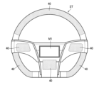
- the sensor 40 may be provided on the steering wheel ST, as indicated by hatching with dots in the figure.
- the screen M1 on which the character is displayed may also be provided on the steering wheel ST.
- the senor 40 may be provided in a center console box 401 located between the driver's seat and the passenger seat, a dashboard 402, an inner panel 403 such as a door or a vehicle side wall, etc., as indicated by hatching with dots in the figure.
- the sensor 40 may also be provided inside a tubular blower 404.
- the tubular blower 404 has a cylindrical body with an air outlet for sending air toward the inside of the vehicle.
- the sensor 40 may be provided in a member (seat cushion, seat back, headrest) constituting at least one of the first row seat 411, the second row seat 412, or the third row seat 413, as indicated by hatching with dots in the figure.
- the sensor 40 may also be provided in the roof 414, the lid 415 for opening and closing the sunroof, the assist grip 416, the upper part of the back of the seatback, the top surface of the dashboard 402, or above the meter hood.
- the sensor 40 may be integrated into the inside of the interior member, or may be positioned so as to protrude from the interior member.
- control unit 100 executes the process shown in FIG. 14.
- the process shown in FIG. 14 is the process shown in FIG. 2 with the addition of a new step S111.
- control unit 100 determines in step S1 that the mode changeover switch 63 is ON (Yes), it determines whether or not there is a possibility of a vehicle collision based on information from the camera 430 (S111). If it determines in step S111 that there is a possibility of a vehicle collision (Yes), the control unit 100 switches the mode to the first mode (S2). If it determines in step S111 that there is no possibility of a vehicle collision (No), it switches the mode to the second mode (S3).
- the control unit 100 may display a message on the monitor M notifying the user of the collision forecast.
- the first sensor may be a tactile sensor 500 that detects displacement in three-dimensional directions.
- the tactile sensor 500 has an operating unit 510 made of sponge, and a substrate 520 that detects the displacement of the operating unit 510.
- the tactile sensor 500 can detect displacement in the X direction, displacement in the Y direction perpendicular to the X direction, and displacement in the Z direction perpendicular to the X and Y directions.
- step S131 determines whether the direction of displacement detected by the tactile sensor 500 is the Y direction (S132). If it is determined in step 132 that the direction of displacement is the Y direction (Yes), the control unit 100 displays an image of a cat relaxing on the monitor M (S11).
- step S132 determines whether the direction of displacement detected by the tactile sensor 500 is the Z direction (S133). If it is determined in step S133 that the direction of displacement is the Z direction (Yes), the control unit 100 displays a video of a cat hanging from the seat back on the screen M1 (S14).
- the vehicle interior system may include a communication unit that communicates with the first sensor, the display unit, and the electric device.
- the electrically powered device may be any of the following devices: ⁇ Height mechanism that moves the seat up and down ⁇ Slide device that moves the seat back and forth ⁇ Movable device that changes the shape of the seat by driving a bag body (air cell) or plate member that operates by letting air in (for example, a device that operates the left and right overhanging parts of the seat cushion or seat back, a device that operates part of the seating surface of the seat back or seat cushion) - A side frame front end lifting mechanism that switches the front end of the seat cushion side frame between a raised up position and a lowered down position (variable cyber angle) A tilt mechanism that moves the cushion pan of the seat cushion up and down.
- ⁇ Height mechanism that moves the seat up and down
- ⁇ Slide device that moves the seat back and forth
- ⁇ Movable device that changes the shape of the seat by driving a bag body (air cell) or plate member that operates by letting air in (for example, a device that operates the left and right overhanging parts of the seat cushion
- a seat back tilt mechanism that tilts the upper part of the seat back forward and backward (a mechanism that tilts the second member 222 in FIG. 10 relative to the first member 221).
- ⁇ Rotation mechanism that rotates the seat on a vertical axis
- ⁇ Mechanism that rotates the ottoman up and down ⁇ Mechanism that rotates the armrest up and down
- Mechanism that expands and contracts the armrest ⁇ Mechanism that switches the armrest between the expanded and bent positions
- the movable device may be one that moves the left and right protruding parts of the seat cushion or the seat back, or one that moves a part of the seating surface of the seat back or the seat cushion.
- the vibration device may be provided in the seat cushion, or in a protruding portion of the seat cushion or seat back.
- the vibration device may be of any type, such as one that has a motor and harness that emits vibrations, one that has an eccentric motor, or one that has a linear motor.
- the control unit may control the speed of movement of a portion of the surface of the interior component to be slower as the degree of intimacy increases.
- the sponge-type tactile sensor may also be embedded in a stuffed toy modeled after a character such as a cat.
- the control unit may recognize the roll, pitch, and yaw directions corresponding to the six axial directions based on information from the tactile sensor. For example, when the control unit detects an input pattern of petting a stuffed toy (holding the stuffed toy in both hands and moving both hands up and down), it may display a cat on the display as if it is being petted by a hand and vibrate the vibration device. Also, for example, the control unit may control multiple air cells so that the action of petting is reproduced on the surface of the seat.
- the control unit will display an indication that the cat's back is being pinched on the display unit and tilt the seat back slightly backward.
- the angrier the cat on the display will be, and the faster the cat punches and vibration device will operate.
- the number of inputs to the sensor per given time period before the character's display action is started may be measured, and the character's display pattern may be determined according to the number of inputs.
- the intimacy level may be calculated in the following manner. - By photographing the occupant using the imaging unit, the number of times they have ridden is counted, and the more times they have ridden, the higher the level of intimacy is. - An occupant recognition unit is provided that recognizes seated occupants by linking with an imaging unit or a smartphone, and stores the number of times the occupant has performed sensor input and displayed a character action. The higher this number, the higher the level of intimacy. - The time that the passenger touches the sensor during the ride is recorded, and the longer the time, the higher the level of intimacy is determined to be. Intimacy level may be reset each time you ride, or it may continue.
- the relationship between the intimacy level and the operation of the electric device may be as follows. - The higher the level of intimacy, the smoother the operation of the electric device will be (at first, operations such as reclining and vibration will be intermittent. For example, the reclining will not be smooth, but will be tilted in stages, the height will increase in stages, and the massage action by the vibration device will be irregular). - The higher the intimacy level, the slower the operating speed of electric devices will be. A coefficient is set for the value of the amount of movement of the electric device, and the amount of movement changes according to the degree of intimacy. The higher the degree of intimacy, the greater the amount of movement. ⁇ The higher the intimacy level, the more variation there is in the character display and the more motorized devices you can choose from. When the intimacy level is low, the display and movement are limited to the vibrator and reclining, but when the intimacy level is high, the lighting, tilt, and air cell movements are added, and the display variations also increase.
- the interior components may be doors, door armrests, steering wheels, dashboards, center consoles, air conditioning vents, etc.
- the interior material may be a material that imitates a part of an animal's body, such as cat ears.
- the interior material may be made of a brushed material.
- the sensor may be a capacitive touch sensor.
- the touch sensors may be provided, for example, on the front end of the seat cushion, the protruding portion of the seat cushion, the protruding portion of the seat back, and the side of the headrest.
- the control unit may display, on the display unit, the action of a cat with its head raised being stroked on its chest, and may repeatedly tilt the seat cushion up and down using the tilt-up mechanism. Also, when there is an input to the touch sensor at the protruding part of the seat cushion, the control unit may display, on the display unit, the action of a cat with its belly facing up being stroked on its belly, and may vibrate a vibration device provided on the seat cushion.
- the color tone of the interior lighting, the display on the screen, the sound, etc. may be changed depending on the time the touch sensor is touched.
- the operation pattern of the vibrator may be changed according to the pressure value input to the touch sensor.
- the control unit may move the vibrator more strongly the harder the touch sensor is pressed.
- the control unit may move the vibrator faster the faster the speed at which the touch sensor is stroked.
- the control unit may display a cat with an angry expression on the display unit when the pressure value from the touch sensor is equal to or greater than a predetermined value.
- the control unit may display a video of a cat moving around on the display unit when the speed at which the touch sensor is stroked is equal to or greater than a predetermined value.
- the control unit may also increase the temperature of a heater provided on the seat when the speed at which the touch sensor is stroked is equal to or greater than a predetermined value.
- the control unit may display a flame on the display unit, and display the flame so that its size increases according to the speed.
- the vehicle interior system may include a seat hardness changing device that changes the hardness of the seat.
- the seat hardness changing device may include, for example, a first pad that supports the user, an air cell, and a second pad that is disposed between the first pad and the air cell.
- the hardness of the first pad is a first hardness
- the hardness of the first pad is a second hardness that is greater than the first hardness.
- the control unit sets the hardness of the first pad to the first state when, for example, a weak force (pressure equal to or greater than a first predetermined value and less than a second predetermined value) is input to the touch sensor for a predetermined period of time.
- the control unit also sets the hardness of the first pad to the second hardness when the speed at which the touch sensor is stroked is equal to or greater than a predetermined value.
- the control unit can put the cat displayed by the display unit into a lazy pose.
- the characters may be animals other than cats, or may be personified objects or living things.
- the vehicle is not limited to an automobile, but may be other vehicles such as motorcycles, trains, etc.
- Examples of methods for manufacturing a vehicle interior system include the following methods.
- a manufacturing method for a vehicle interior system comprising an interior member to be placed within a vehicle, an electric device that moves a portion of a surface of the interior member back and forth, a first sensor to which information is input by a user, a display unit, and a control unit, wherein the control unit is capable of displaying a character using the display unit, and moves the character based on information from the first sensor and operates the electric device with a movement corresponding to the movement of the character
- the manufacturing method for a vehicle interior system having the steps of attaching the electric device to the interior member, and connecting the electric device, the display unit, and the first sensor to the control unit.
- the first sensor or the second sensor may be a sensor that detects biological information (at least one of brain waves, facial expressions, gaze, breathing, heart rate, pulse rate, voice, etc.).
- the collision detection unit may be a vehicle distance sensor that detects the distance between the vehicle and the vehicle ahead.
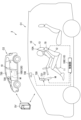
- the vehicle system 2 is a system capable of transmitting a message from a first vehicle C1 to a second vehicle C2.
- the vehicle system 2 includes the first vehicle C1, the second vehicle C2, and a server SV.
- the first vehicle C1 is equipped with a seat 10, an ornament 720 as an example of an interior member, a camera 730 as an example of a collision detection unit, a monitor M as an example of a display unit, and a control unit 100.
- the seat 10, ornament 720, camera 730, and monitor M are arranged in the first vehicle C1, more specifically, in a position facing the passenger compartment.
- the seat 10 is the driver's seat.
- the seat 10 has a seat body 10A and a vibration device 70 as an example of an electric device.
- the seat body 10A is a member having a seating surface that supports the user.
- the seat body 10A is equipped with a seat cushion 11, a seat back 12, and a headrest 13.
- the seat cushion 11, the seat back 12, and the headrest 13 each have a metal frame that forms the skeleton, a pad that covers the frame, and a skin that covers the pad.
- the pad is made of urethane foam or the like.
- the skin is made of synthetic leather, fabric, or the like.
- the upper surface of the seat cushion 11 forms the seating surface.
- the front surfaces of the seat back 12 and the headrest 13 form the seating surface.
- the vibration device 70 is a device that vibrates the seating surface of the seat 10.
- the vibration device 70 is provided in the seat back 12.
- one vibration device 70 is provided on each of the left and right sides of the seating surface of the seat back 12.
- the ornament 720 is a stuffed cat toy.
- the ornament 720 is attached to the dashboard D of the first vehicle C1.
- the ornament 720 has a sensor 721, a light 722, a cushion 723, and a cover 724.
- Sensor 721 is a pressure sensor that detects contact between ornament 720 and the user. Sensor 721 is provided on the body of ornament 720. The position of sensor 721 is arbitrary, and for example, sensor 721 may be located on the head of ornament 720.
- the light 722 can emit light of several different colors.
- the light 722 is located, for example, between the cushion 723 and the skin 724.
- the light 722 emits light to the outside, for example, through a hole or a transparent part provided in the skin 724.
- the light 722 is provided in the body part of the ornament 720.
- the position of the light 722 is arbitrary, and for example, the sensor 721 may be provided in the head of the light 722.
- the light 722 may also be provided on the outer surface of the skin 724.
- Cushion 723 is made of urethane foam or the like, and covers sensor 721.
- the outer shape of cushion 723 resembles a cat.
- the surface 724 is made of synthetic leather, cloth, or the like, and covers the cushion 723 .
- Monitor M has a screen M1 that displays an image.
- the image displayed on monitor M can be changed by control unit 100.
- Monitor M can be placed on dashboard D, for example, so as to be located below the rearview mirror.
- the camera 730 is a camera that captures images of the area ahead of the first vehicle C1. Image information captured by the camera 730 is output to the control unit 100.
- the control unit 100 has a CPU, ROM, RAM, rewritable non-volatile memory, etc. (not shown), and executes pre-stored programs.
- the control unit 100 acquires information from the camera 730 and the sensor 721 in the ornament 720.
- the control unit 100 controls the monitor M and the vibration device 70.
- the control unit 100 is capable of communicating with the server SV.
- first control unit 110 and the second control unit 120 have the same functions, the functions explained for one of the first control unit 110 and the second control unit 120 are also similarly possessed by the other one.
- the first control unit 110 selects a message according to the number of times the user kneads the ornament 720 within a specified time period (hereinafter also referred to as the "number of inputs"). In detail, the first control unit 110 counts up the number of inputs by one when the pressure value acquired from the sensor 721 becomes equal to or greater than a specified value, and thereafter counts up the number of inputs each time the pressure value rises from a value less than the specified value to a value equal to or greater than the specified value within the specified time period.
- the first control unit 110 selects the first message, "Thank you for letting me go.” If the number of inputs within the specified time is two, the first control unit 110 selects the second message, "I'm sorry.” If the number of inputs within the specified time is three, the first control unit 110 selects the third message, "I will change lanes.”
- the first control unit 110 may be configured to select a message indicating a change from the right lane to the left lane if, for example, the number of inputs within a specified time is four.
- the second control unit 120 When the second control unit 120 receives the first message from the first control unit 110, it displays an image of text indicating the first message and a cat character on the screen M1 of the monitor M, as shown in FIG. 19. The second control unit 120 moves the character in a manner corresponding to the first message acquired from the first control unit 110. For example, the second control unit 120 displays an image of the text "Thanks for letting me have your seat” and a video of a cat nodding.
- the second control unit 120 When the second control unit 120 receives the third message from the first control unit 110, as shown in FIG. 21, it displays an image of text indicating the third message and a video of a cat moving in a manner corresponding to the third message on the screen M1 of the monitor M. For example, the second control unit 120 displays an image of the text "Changing lanes" and a video of a cat crossing the road.
- the first control unit 110 has a function of turning on the light 722 in a lighting pattern corresponding to the selected message. For example, when the first message is selected, the first control unit 110 causes the light 722 to emit red light. When the second message is selected, the first control unit 110 causes the light 722 to emit blue light. When the third message is selected, the first control unit 110 causes the light 722 to emit yellow light.
- the lighting pattern is not limited to colors, and may be, for example, a lighting pattern with different blinking intervals.
- the second control unit 120 When the second control unit 120 receives a message from the first control unit 110, it has the function of turning on the light 722 in a lighting pattern corresponding to the received message, and activating the vibration device 70 in a vibration pattern corresponding to the received message.
- the lighting pattern can be, for example, the same pattern as when the first control unit 110 selects a message.
- the vibration pattern can be, for example, a pattern in which the vibration device 70 is activated a different number of times.
- the vibration pattern corresponding to the first message can be set to a pattern in which at least one of the left and right vibration devices 70 vibrates twice during a second specified time.
- the vibration pattern corresponding to the second message can be set to a pattern in which at least one of the left and right vibration devices 70 vibrates six times during a second specified time.
- the vibration pattern corresponding to the third message can be set to a pattern in which the vibration moves from left to right by activating the left vibration device 70 and then the right vibration device 70.
- the first control unit 110 also has a function of predicting a collision between the first vehicle C1 and the second vehicle C2 based on information from the camera 730.
- the first control unit 110 predicts a collision between the first vehicle C1 and the second vehicle C2, it transmits a collision message to the second control unit 120 to forecast a vehicle collision.
- the collision message may be, for example, a message such as "There is a possibility that a following vehicle will collide with your vehicle from behind.”
- the second control unit 120 When the second control unit 120 receives a collision message from the first control unit 110, the second control unit 120 has a function of activating the vibration device with a vibration pattern corresponding to the received collision message.
- the vibration pattern corresponding to the collision message can be set to, for example, a pattern that causes the vibration device 70 to vibrate continuously for a second predetermined time or longer.
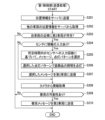
- the first control unit 110 repeatedly executes the transmission process shown in FIG. 22.
- the first control unit 110 transmits the location information of the first vehicle C1 together with the vehicle ID (identification information) of the first vehicle C1 to the server SV using a GPS (Global Positioning System) or the like (S201).
- the second control unit 120 which has the same functions as the first control unit 110, also constantly transmits the vehicle ID and location information of the second vehicle C2 to the server SV.
- the server SV associates the vehicle ID and location information for each vehicle and constantly updates them.
- the first control unit 110 acquires the vehicle ID and location information of the other vehicle from the server SV (S202). After step S202, the first control unit 110 determines whether or not a second vehicle C2 is present in the vicinity of the first vehicle C1 (for example, within a radius of several tens of meters) based on the vehicle ID and location information acquired in step S202 (S203).
- step S203 If it is determined in step S203 that the second vehicle C2 is not present (No), the first control unit 110 ends this process. If it is determined in step S203 that the second vehicle C2 is present (Yes), the first control unit 110 determines whether information has been input to the sensor 721 by determining whether the pressure value acquired from the sensor 721 is equal to or greater than a predetermined value (S204).
- step S204 If it is determined in step S204 that information has been input to the sensor 721 (Yes), the first control unit 110 calculates the number of inputs to the sensor 721 within a predetermined time period, and selects a message and a lighting pattern based on the calculated number of inputs (S205). After step S205, the first control unit 110 turns on the lights 722 of the ornament 720 in the selected lighting pattern (S206).
- step S206 the first control unit 110 transmits the selected message to the second vehicle C2 via the server SV (S207).
- the first control unit 110 acquires information from the camera 730 (S208). Note that if it is determined in step S204 that no information has been input to the sensor 721 (No), the control unit 51 skips steps S205 to S207 and proceeds to the processing of step S208.
- the first control unit 110 determines whether or not there is a possibility that the first vehicle C1 will collide with the second vehicle C2 based on the information obtained from the camera 730 (S209). If it is determined in step S209 that there is a possibility of a collision (Yes), the first control unit 110 transmits a collision message to the second control unit 120 of the second vehicle C2 (S210) and ends this process. If it is determined in step S209 that there is no possibility of a collision (No), the first control unit 110 ends this process as is.
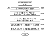
- the second control unit 120 repeatedly executes the reception process shown in FIG. In the reception process, the second control unit 120 determines whether or not a message has been received from the first vehicle C1 (S231). If it is determined in step S231 that a message has not been received (No), the second control unit 120 ends this process.
- step S231 If it is determined in step S231 that a message has been received (Yes), the second control unit 120 selects an action, a vibration pattern, and a lighting pattern for the cat based on the received message (S232). After step S232, the second control unit 120 displays the received message and a video of the cat performing the selected action on the screen M1 (S233).
- the second control unit 120 activates the vibration device 70 with the selected vibration pattern (S234), and turns on the light 722 of the ornament 720 with the selected lighting pattern (S235), and ends this process.
- the control unit 100 displays an image conveying gratitude to the user of the second vehicle C2 on the screen M1.
- the user of the first vehicle C1 can send the first message of gratitude to the second vehicle C2 simply by performing a simple operation such as kneading the ornament 720 once. Furthermore, the user of the second vehicle C2 can feel that he or she has done a good deed by seeing the words of gratitude and the video of the cat nodding displayed on the screen M1.
- the ornament 720 of the first vehicle C1 and the ornament 720 of the second vehicle C2 both glow red. This allows the user who sent the message and the user who received the message to intuitively know that they have sent or received a message expressing gratitude by looking at the ornament 720 glowing red.
- the vibration device 70 vibrates twice in the seat 10 of the second vehicle C2. This allows the user who receives the message to intuitively know that they have received a message expressing gratitude.
- a second message is transmitted from the first vehicle C1 to the second vehicle C2.
- the second control unit 120 receives the second message, it displays an image conveying an apology to the user of the second vehicle C2 on the screen M1, as shown in FIG. 20.
- the user of the first vehicle C1 can send the second message conveying an apology to the second vehicle C2 simply by performing a simple operation such as kneading the ornament 720 twice. Furthermore, the user of the second vehicle C2's anger is alleviated by the apology text and the video of the cat bowing displayed on the screen M1.
- the ornament 720 of the first vehicle C1 and the ornament 720 of the second vehicle C2 both glow blue. This allows the user who sent the message and the user who received it to intuitively know that they have sent or received a message conveying an apology by looking at the ornament 720 glowing blue.
- the vibration device 70 vibrates six times in the seat 10 of the second vehicle C2. This allows the user who receives the message to intuitively know that they have received a message conveying an apology.
- a third message is transmitted from the first vehicle C1 to the second vehicle C2.
- the second control unit 120 receives the third message, it displays an image on the screen M1 informing the user of the second vehicle C2 of the lane change, as shown in FIG. 21.
- the user of the first vehicle C1 can send a third message informing the second vehicle C2 of a lane change simply by performing a simple operation such as kneading the ornament 720 three times.
- the user of the second vehicle C2 is also soothed by the text indicating a lane change and the video of a cat displayed on the screen M1.
- the ornament 720 of the first vehicle C1 and the ornament 720 of the second vehicle C2 both glow yellow. Furthermore, in the seat 10 of the second vehicle C2, the vibration device 70 on the left side vibrates, and then the vibration device 70 on the right side vibrates. This allows the user who receives the message to know that the lane will be changed from the left lane to the right lane.
- the cat character displayed on the monitor M of the second vehicle C2 moves in a way that corresponds to the message, enhancing entertainment value.
- Messages are sent when the user touches the ornament 720, which adds to the entertainment value.
- the vibration device 70 operates in response to a message, allowing the user to intuitively understand the message based on the vibration pattern.
- the lights come on in a pattern that corresponds to the message, so you can intuitively understand the message by the lighting pattern.
- the vibration device 70 operates with a vibration pattern corresponding to the collision message, so that the user of the second vehicle C2 can be informed of the vehicle collision predicted by the first vehicle C1.
- the vehicle system 601 includes a seat 610 as an example of an interior member.
- the seat 610 includes a seat body 610A having a configuration substantially similar to the seat body 10A according to the fifth embodiment, a first vibration device 671 and a second vibration device 672 having a configuration substantially similar to the vibration device 70 according to the fifth embodiment, and further includes a first sensor 41 and a second sensor 42.
- FIG. 25 illustrates the configuration provided on the first vehicle C1, this configuration is also provided on the second vehicle C2.
- the first vehicle C1 and the second vehicle C2 do not include the ornament 20 of the fifth embodiment.
- the seat cushion 11 has a base portion 11A located in the left-right center, and overhanging portions 11B located on both the left and right outer sides of the base portion 11A.
- the base portion 11A has a seating surface F that contacts and supports the user's buttocks and thighs from below.
- the overhanging portions 11B overhang from the seating surface F of the base portion 11A towards the user to support the sides of the user's thighs and buttocks.
- the seat back 12 has a base portion 12A located in the left-right center and overhanging portions 12B located on both the left and right outer sides of the base portion 12A.
- the base portion 12A has a seating surface F that comes into contact with the user's back and supports the back from behind.
- the overhanging portions 12B overhang toward the user from the seating surface F of the base portion 12A to support the sides of the user's upper body.
- the seat cushion 11 has a first vibration device 671 and a first sensor 41.
- the headrest 13 has a second vibration device 672 and a second sensor 42.
- the first sensor 41 and the second sensor 42 are pressure sensors that detect pressure from the user.
- the first sensor 41 and the second sensor 42 are provided at positions that avoid the seating surface F, i.e., at positions away from the seating surface F.
- the first sensors 41 are provided on the left and right protruding portions 11B of the seat cushion 11, one each.
- the second sensor 42 is disposed at a position different from that of the first sensor 41. More specifically, the second sensor 42 is provided on each of the left and right side surfaces of the headrest 13.
- the first sensor 41 and the second sensor 42 are each located between the skin and the pad.
- the first vibration device 671 is disposed at a position corresponding to the first sensor 41 (near the first sensor 41). In other words, the first vibration device 671 and the first sensor 41 are provided on the same member (the seat cushion 11).
- first vibration devices 671 are provided side by side in the base portion 11A of the seat cushion 11. Each first vibration device 671 is located between the left and right first sensors 41. By arranging the first vibration device 671 at a position (component) corresponding to the first sensor 41, the second vehicle C2 having the same seat 610 as the first vehicle C1 is provided with a first vibration device 671 that is located at a position corresponding to the first sensor 41 provided in the first vehicle C1.
- the second vibration device 672 is disposed at a position corresponding to the second sensor 42 (near the second sensor 42). In other words, the second vibration device 672 and the second sensor 42 are provided on the same member (the headrest 13).
- two second vibration devices 672 are provided side by side on the left and right in the headrest 13. Each second vibration device 672 is located between the left and right second sensors 42. By arranging the second vibration device 672 at a position (component) corresponding to the second sensor 42, the second vehicle C2 having the same seat 610 as the first vehicle C1 is provided with a second vibration device 672 located at a position corresponding to the second sensor 42 provided in the first vehicle C1.
- the first control unit 110 can acquire information from the first sensor 41 and the second sensor 42.
- the first control unit 110 selects a first message based on a signal from the first sensor 41, and selects a second message different from the first message based on a signal from the second sensor 42. Note that in the sixth embodiment, the contents of the first message and the second message are the same as those in the fifth embodiment.
- the second control unit 120 which is the control unit 100 of the second vehicle C2 receives the first message from the first vehicle C1, it activates the first vibration device 671 of the second vehicle C2.
- the second control unit 120 receives the second message from the first vehicle C1, it activates the second vibration device 672 of the second vehicle C2.
- the first control unit 110 executes the process shown in FIG. 26.
- the process in FIG. 26 includes steps S201 to S203 and S207 to S210 in the process in FIG. 22, as well as new steps S251 to S254.
- step S203 determines whether information has been input to the first sensor 41 (S251). If the first control unit 110 determines in step S251 that information has been input to the first sensor 41 (Yes), it selects the first message (S252).
- step S251 If it is determined in step S251 that no information has been input to the first sensor 41 (No), the first control unit 110 determines whether or not information has been input to the second sensor 42 (S253). If it is determined in step S253 that information has been input to the second sensor 42 (Yes), the first control unit 110 selects the second message (S254).
- step S253 If it is determined in step S253 that no information has been input to the second sensor 42 (No), the first control unit 110 proceeds to the process of step S208. After step S252 or step S254, the first control unit 110 transmits the selected message to the second vehicle C2 (S207).
- the second control unit 120 executes the process shown in FIG. 27.
- the process in FIG. 27 includes steps S231 and S233 in the process in FIG. 23, as well as new steps S271 and S272.
- step S231 If the second control unit 120 determines in step S231 that a message has been received (Yes), it selects an action for the cat and a vibration device to activate based on the message (S271). After step S271, the second control unit 120 displays the received message and a video of the cat performing the selected action on the screen M1 (S233). After step S233, the second control unit 120 activates the selected vibration device (S272) and ends this process.
- the control unit 100 for example, in a situation where the first vehicle C1 suddenly cuts in front of the second vehicle C2, when the user of the first vehicle C1 presses either the left or right side of the headrest 13, the second message is transmitted from the first vehicle C1 to the second vehicle C2.
- the second control unit 120 receives the second message, it displays an image conveying an apology to the user of the second vehicle C2 on the screen M1 and vibrates the second vibration device 672 of the headrest 13.
- the user of the first vehicle C1 can send the second message conveying an apology to the second vehicle C2 by simply performing a simple operation such as pressing the side of the headrest 13. Furthermore, when the user of the first vehicle C1 presses the headrest 13, the headrest 13 of the second vehicle C2 vibrates, allowing the user of the second vehicle C2 to know the position (component) that the user touched in the first vehicle C1. Therefore, the user of the first vehicle C1 and the user of the second vehicle C2 can come into contact with each other through the seat 610.
- a first message is transmitted from the first vehicle C1 to the second vehicle C2.
- the second control unit 120 receives the first message, as shown in FIG. 19, it displays an image conveying gratitude to the user of the second vehicle C2 on the screen M1 and vibrates the first vibration device 671 of the seat cushion 11.
- the user of the first vehicle C1 can send a first message of gratitude to the second vehicle C2 by simply performing a simple operation such as pressing the protruding portion 11B of the seat cushion 11. Furthermore, when the user of the first vehicle C1 presses the seat cushion 11, the seat cushion 11 of the second vehicle C2 vibrates, allowing the user of the second vehicle C2 to know the position (component) that the user touched in the first vehicle C1. Therefore, the user of the first vehicle C1 and the user of the second vehicle C2 can come into contact with each other via the seat 610.
- the seat is not limited to the structure of the above embodiment.
- the seat 200 may have a seat cushion 210, a seat back 220, and a headrest 230, as well as an ottoman 240 and an armrest 250.
- a console box 300 may also be provided next to the seat 200.
- the seat back 220 has a first member 221 that is rotatably supported on the seat cushion 210, and a second member 222 that is rotatably supported on the upper portion of the first member 221 and has a headrest 230 provided on the upper portion.
- the sensor 40 through which information is input by the user can be disposed in at least one of the following locations.
- Left and right overhanging portions 211 of the seat cushion 210 The front end surface of the seat cushion 210
- Left and right protruding portions 222A of the second member 222 The left and right side surfaces or rear surface of the seat back 220
- the left and right side surfaces of the ottoman 240 The left and right inner side surfaces or left and right outer side surfaces of the console box 300
- the sensor 40 may be the first sensor 41, the second sensor 42, or another sensor for transmitting a message different from the first sensor 41 and the second sensor 42.
- the sensor 40 may be provided on the steering wheel ST, as indicated by hatching with dots in the figure.
- the screen M1 on which the character is displayed may also be provided on the steering wheel ST.
- the senor 40 may be provided in a center console box 401 located between the driver's seat and the passenger seat, a dashboard 402, an inner panel 403 such as a door or a vehicle side wall, etc., as indicated by hatching with dots in the figure.
- the sensor 40 may also be provided inside a tubular blower 404.
- the tubular blower 404 has a cylindrical body with an air outlet for sending air toward the inside of the vehicle.
- the sensor 40 may be provided in a member (seat cushion, seat back, headrest) constituting at least one of the first row seat 411, the second row seat 412, or the third row seat 413, as indicated by hatching with dots in the figure.
- the sensor 40 may also be provided in the roof 414, the lid 415 for opening and closing the sunroof, the assist grip 416, the upper part of the back of the seatback, the top surface of the dashboard 402, or above the meter hood.
- the sensor 40 may be integrated into the inside of the interior member, or may be positioned so as to protrude from the interior member.
- the sensor may be a tactile sensor 500 that detects displacement in three-dimensional directions.
- the tactile sensor 500 has an operating unit 510 made of sponge, and a substrate 520 that detects the displacement of the operating unit 510.
- the tactile sensor 500 can detect displacement in the X direction, displacement in the Y direction perpendicular to the X direction, and displacement in the Z direction perpendicular to the X and Y directions.
- control unit 100 may select a message based on the direction of displacement obtained from the tactile sensor 500. For example, the control unit 100 may select a message expressing gratitude when the tactile sensor 500 is operated in a circular motion.
- the sponge-type tactile sensor may also be embedded in a stuffed toy modeled after a character such as a cat.
- the control unit may recognize the roll, pitch, and yaw directions corresponding to the six axial directions based on information from the tactile sensor. For example, when the control unit detects an input pattern of rubbing a stuffed toy (holding the stuffed toy in both hands and moving both hands up and down), it may select a message expressing gratitude. Also, for example, the control unit may control multiple air cells so that the action of rubbing is reproduced on the surface of a seat in the second vehicle.
- the first control unit may select the message "Thank you” when it determines that strong pressure has been applied to the right side of the stuffed animal.
- the first control unit may select the message “I'm sorry” when it determines that strong pressure has been applied to the left side of the stuffed animal.
- the first control unit may select the message “I'll go first” when it determines that the stuffed animal has been squeezed multiple times.
- the first control unit may select the message "I'll go first” when it determines that the stuffed animal has been pinched.
- the first control unit may decide whether or not to transmit the selected message based on information from a sensor.
- a transmitting sensor may be provided on the top of the stuffed animal, and the selected message may be transmitted when the transmitting sensor is tapped twice.
- the electrically powered device may be any of the following devices: A reclining device that tilts the seat back; A height mechanism that moves the seat up and down; A sliding device that moves the seat back and forth; A movable device that changes the shape of the seat by driving a bag (air cell) or a plate member that is operated by letting air in; A side frame front end lifting mechanism that switches the front end of the side frame of the seat cushion between an up position where it is raised and a down position where it is lowered; A tilt mechanism that moves the cushion pan of the seat cushion up and down; A center folding mechanism that tilts the upper part of the seat back back and forth (a mechanism that tilts the second member 222 in FIG.
- a mechanism for rotating the seat on a vertical axis A cushion front-rear adjustment mechanism for adjusting the length of the front end of the seat cushion; A mechanism for rotating the ottoman up and down; A mechanism for rotating the armrest up and down; A mechanism for extending and retracting the armrest; A mechanism for switching the armrest between an extended state and a bent state; Lighting; and Headrest speakers (The headrest speakers may rotate or move in at least one of the following directions: front-rear, left-right, up-down.) - A heater installed in the seat back or seat cushion - A seat blower, which is a seat air conditioning device that circulates air on the surface of the seat cushion and seat back
- the movable device may be one that moves the left and right protruding parts of the seat cushion or the seat back, or one that moves a part of the seating surface of the seat back or the seat cushion.
- the air cell may be connected to an air pump by an air tube, and when air is injected, it may expand toward the seated occupant and press against the occupant.
- the air cell may be placed at a position corresponding to the occupant's lower back like a lumbar support, or may be provided in multiple places on the seat.
- the vibration device may be provided on a protruding portion of the seat cushion or seat back.
- the vibration device may be of any type, such as one that has a motor and harness that emits vibrations, one that has an eccentric motor, or one that has a linear motor.
- the display unit may be located in any position, such as on the instrument panel, center console, steering wheel, meter, back of the seat, side of the door, or decorative item.
- the display unit may also be a projection device that projects an image.
- the display unit may also be a mobile device such as a smartphone or tablet carried by the seat occupant.
- the control unit may select a message to warn the driver and tilt the seat back slightly backward.
- the number of inputs to the sensor per given time period before the character's display action is started may be measured, and the character's display pattern may be determined according to the number of inputs.
- the interior components may be doors, door armrests, steering wheels, dashboards, center consoles, air conditioning vents, etc.
- the interior material may be a material that imitates a part of an animal's body, such as cat ears.
- the interior material may be made of a brushed material.
- the sensor may be a capacitive touch sensor.
- the touch sensors may be provided, for example, on the front end of the seat cushion, the protruding portion of the seat cushion, the protruding portion of the seat back, and the side of the headrest.
- the color tone of the interior lighting, the display on the screen, the sound, etc. may be changed depending on the time the touch sensor is touched.
- the operation pattern of the vibrator may be changed according to the pressure value input to the touch sensor.
- the control unit may move the vibrator more strongly the harder the touch sensor is pressed.
- the control unit may move the vibrator faster the faster the touch sensor is stroked.
- the character may be an animal other than a cat, or may be an anthropomorphized object or living thing.
- the character may be set in advance, and may be, for example, an image of a deformed passenger.
- the vehicle is not limited to an automobile, but may be other vehicles such as motorcycles, trains, etc.
- the collision detection unit may be a vehicle distance sensor that detects the distance between the vehicle and the vehicle ahead.
- the first sensor or the second sensor may be a sensor that detects biological information (at least one of brain waves, facial expressions, gaze, breathing, heart rate, pulse rate, voice, etc.).
- Examples of methods for manufacturing a vehicle interior system include the following methods.
- a manufacturing method for a vehicle system capable of sending a message from a first vehicle to a second vehicle, the first vehicle comprising: at least one sensor that is provided in an interior member excluding a screen and an operation unit that operates an object on the screen and detects contact with a user; and a first control unit; the first control unit selecting one message from a plurality of pre-stored messages based on information obtained from the sensor that changes depending on how the user touches the interior member, and transmitting the selected message to the second vehicle, the manufacturing method for a vehicle interior system comprising the steps of: attaching the sensor to the interior member; attaching the interior member and the first control unit to the first vehicle; and connecting the sensor to the control unit.
- the first and second vehicles may be able to communicate directly without going through a server.
- the interior parts may be any interior parts other than the screen and the operation part for operating the objects on the screen.
- the method of determining the recipient may be, for example, as follows. - A method in which the passenger's gestures (pointing direction, or hand movements to indicate forward, backward, left, right, and diagonal) are captured by a camera and the recipient is determined based on the information from the camera. A method of determining the transmission partner based on information from a switch or sensor (which has a cursor button or a sensor part that determines direction) that can input forward, backward, left, right, and diagonal directions.
- a switch or sensor which has a cursor button or a sensor part that determines direction
- the first control unit may determine the direction from the vehicle itself to each of the second vehicles based on the position information of the vehicle itself and the position information of each of the second vehicles, and may determine as the destination of the message the second vehicle whose direction matches the direction specified by the occupant, which is determined from information from a camera or the like.
- message patterns for each category such as “greetings,””thanks,””apology,””roadenvironment,” and “vehicle movement (yielding)” may be set.
- the sensor input pattern is not character input, but a variation in touch, i.e. a single touch generates a message and does not include input from the display.
- the association between the message pattern and the sensor can also be set in advance.
- the way of touching the sensor (interior component) to select the message "Thank you” can be selected from applying strong pressure to the sensor (the direction and strength of the pressure), drawing a circle around the sensor (the way the sensor is touched by an electrostatic sensor), touching the sensor on the door (the position where the sensor is installed), etc.
- the cat may display an action of stroking the cheek.
- the cat may display an action of curling up.
- an action display of a cat stroking its cheek may be displayed, and the air cell in the recipient's seat may be weakly activated.
- a vibration device in the recipient's seat back may vibrate.
- the recipient's air conditioning system may operate its air vent to blow air toward the occupant in the driver's seat.
- multiple vibration device operation patterns may be transmitted to the other vehicle in a wave-like manner.
- the vibration device may transmit vibrations to the other vehicle in a position corresponding to the direction of the transmitting vehicle's position (when moving from the right lane to the left lane, the right side of the seat of the other vehicle may vibrate).
- the air cell may be connected to an air pump by an air tube, and when air is injected, it may expand and press against the occupant.
- the air cell may be in the lower back like a lumbar support, or multiple air cells may be provided so that the shape can be changed more locally.
- the ornament may have a vibration device.
- the ornament on the second vehicle may vibrate.
- the color of the lighting that changes in response to the message is “red” for messages of "gratitude” and “blue” for messages of "apology,” but the color assignment for each message can be set arbitrarily.
- the first control unit may select a message based on a change in the force input to the sensor (the amount of pressure applied to the sensor). For example, the first control unit may select the message “I'm sorry” when strong pressure is applied to the sensor. The first control unit may select the message “I'll give way” when the sensor is squeezed multiple times.
- the relationship between the way the sensor is touched and the message can be set arbitrarily.
- the first control unit may select the message “I'm sorry” when a force in the forward/backward direction is applied to the sensor.
- the first control unit may select the message “I'll give way” when a force in the left/right direction is applied to the sensor.
- the first control unit may select a message depending on the number of fingers touching the sensor. For example, when a force in the forward/backward direction is applied to the sensor with three fingers, the message "Thank you” may be selected.
- the second control unit may increase the heater temperature of the other vehicle in response to the message "Thank you,” or may operate a vibration device of the other vehicle in response to the message "Thank you.”
- the first control unit may select a message based on the number of times a force is applied to the sensor within a predetermined time (the number of inputs within a predetermined time). For example, the first control unit may select the message "I'm sorry” when the sensor receives multiple inputs quickly (e.g., three times per second), or may select the message "Thank you” when the sensor receives a slow input (e.g., once per second).
- the multiple sensors may be attached at any desired positions.
- the first control unit may select the message "Thank you” when the user touches a sensor on the side of the headrest.
- the first control unit may select the message "I'm sorry” when the user touches a sensor on the top surface of the headrest.
- the first control unit may select the message "No thanks” when the user touches a sensor on the back of the headrest.
- the first control unit may select the message "I'll go ahead” when the user touches a sensor on the door.
- the second control unit may operate an electric device that is not located at a position corresponding to the first sensor provided in the first vehicle. For example, if the first sensor is located in a seat cushion, the second control unit may operate a vibration device located in a headrest when the second control unit receives the first message.
- the type of message may be the direction of travel of the vehicle. Lighting may be provided on the door.
- the control unit may change the intensity of the light.
- the first control unit may select an action for the character to be moved on the screen of the second vehicle, a vibration pattern for the vibration device of the second vehicle, and a lighting pattern for the lights of the second vehicle based on the selected message.
- the first control unit may transmit the message, action, vibration pattern, and lighting pattern to the second control unit, and the second control unit may display the screen, operate the vibration device, and turn on the lights based on the received message, action, vibration pattern, and lighting pattern.
Landscapes
- Engineering & Computer Science (AREA)
- Aviation & Aerospace Engineering (AREA)
- Transportation (AREA)
- Mechanical Engineering (AREA)
- Seats For Vehicles (AREA)
Abstract
娯楽性を高めることができる車両内装システムを提供する。車両内装システム(1)は、車両内に配置される内装部材(シート10)と、内装部材の表面の一部を往復動作させる電動デバイス(振動デバイス23)と、ユーザから情報が入力される第1センサ(41)と、表示部(モニタM)と、制御部(100)と、を備える。制御部(100)は、表示部によってキャラクタを表示可能であり、第1センサ(41)からの情報に基づいて、キャラクタを動かすとともに、キャラクタの動作に対応した動きで電動デバイスを作動させる。
Description
本開示は、内装部材と制御部を備えた車両内装システムに関する。
従来、パワーシートに設けられたセンサをユーザが操作することで、シートバックなどの可動部材が動くシステムが知られている(特許551228号公報参照)。
しかしながら、従来技術では、ユーザによるセンサの操作に応じて可動部材が動くだけなので、娯楽性が不足していた。
そこで、娯楽性を高めることができる車両内装システムを提供することが望まれている。
上述の背景に鑑み、車両内に配置される内装部材と、内装部材の表面の一部を往復動作させる電動デバイスと、ユーザから情報が入力される第1センサと、表示部と、制御部と、を備える車両内装システムを開示する。
制御部は、表示部によってキャラクタを表示可能であり、第1センサからの情報に基づいて、キャラクタを動かすとともに、キャラクタの動作に対応した動きで電動デバイスを作動させる。
制御部は、表示部によってキャラクタを表示可能であり、第1センサからの情報に基づいて、キャラクタを動かすとともに、キャラクタの動作に対応した動きで電動デバイスを作動させる。
この構成によれば、ユーザが第1センサに情報を入力すると、制御部が、キャラクタを動かし、キャラクタ動作に対応した動きで電動デバイスを作動させるので、ユーザが内装部材を介してキャラクタの存在を感じることができ、娯楽性を高めることができる。
また、第1センサは、圧力センサであり、制御部は、圧力センサからの圧力値に基づいて、キャラクタと電動デバイスを動かしてもよい。
また、第1センサは、三次元方向の変位を検出する触覚センサであり、制御部は、触覚センサから取得した変位の方向に基づいて、キャラクタと電動デバイスを動かしてもよい。
また、制御部は、ユーザとキャラクタとの親密度を算出し、親密度に応じてキャラクタおよび電動デバイスの少なくとも一方の動作を変更してもよい。
これによれば、ユーザとキャラクタとの親密度に応じて、キャラクタおよび電動デバイスの少なくとも一方の動作が変更されるので、娯楽性をより高めることができる。
また、制御部は、第1センサへの情報の入力時間の累積値が大きいほど、親密度を高くしてもよい。
また、制御部は、第1センサに情報が入力されてから次に第1センサに情報が入力されるまでの時間間隔が所定値以下の場合に、親密度を高くしてもよい。
また、制御部は、所定時間当たりの第1センサへの情報の入力回数が所定回数以上の場合に、親密度を高くしてもよい。
また、車両内装システムは、ユーザから情報が入力される第2センサであって、第1センサとは異なる位置に配置される第2センサをさらに備え、制御部は、第1センサに情報が入力された場合、キャラクタを第1動作で動かし、第2センサに情報が入力された場合、キャラクタを第1動作とは異なる第2動作で動かしてもよい。
これによれば、操作するセンサに応じてキャラクタの動作が異なるので、娯楽性をより高めることができる。
また、内装部材は、シートであり、第1センサは、シートの着座面を避けた位置に配置されていてもよい。
また、車両内装システムは、制御部を、キャラクタと電動デバイスを連動させない第1モードと、キャラクタの動作に対応した動きで電動デバイスを作動させる第2モードと、に切り替えるスイッチをさらに備えていてもよい。
また、制御部は、第2モードの実行中に、車両に設けられた衝突検知部からの情報に基づいて車両の衝突を予測した場合、第2モードを終了して、第1モードを実行してもよい。
この構成によれば、第2モードの実行中に車両が衝突しそうになった場合には、第2モードが終了するので、ユーザに異変を感じさせることができ、例えばユーザが衝突に備えた姿勢をとることができる。
さらに、従来、第1車両から第2車両にメッセージを送信可能な車両システムとして、複数のメッセージを画面に表示し、複数のメッセージから一のメッセージをユーザが選択可能な車両システムが知られている(特開2007-148524号公報参照)。
さらに、従来、第1車両から第2車両にメッセージを送信可能な車両システムとして、複数のメッセージを画面に表示し、複数のメッセージから一のメッセージをユーザが選択可能な車両システムが知られている(特開2007-148524号公報参照)。
しかしながら、従来技術では、ユーザが、画面に表示された複数のメッセージを確認する手間が生じるので、メッセージを送信する操作が煩雑になるといった問題があった。
そこで、第1車両から第2車両にメッセージを送信する操作を簡易にすることが望まれている。
上述の背景に鑑み、一態様における車両システムは、第1車両から第2車両にメッセージを送信可能なシステムである。
第1車両は、少なくとも1つのセンサと、第1制御部と、を備える。
センサは、画面および画面上の対象を操作する操作部を除く内装部材に設けられる。センサは、ユーザとの接触を検知する。
第1制御部は、センサから取得した、ユーザによる内装部材の触り方によって変化する情報に基づいて、予め記憶している複数のメッセージの中から1のメッセージを選択し、選択したメッセージを第2車両に送信する。
第1車両は、少なくとも1つのセンサと、第1制御部と、を備える。
センサは、画面および画面上の対象を操作する操作部を除く内装部材に設けられる。センサは、ユーザとの接触を検知する。
第1制御部は、センサから取得した、ユーザによる内装部材の触り方によって変化する情報に基づいて、予め記憶している複数のメッセージの中から1のメッセージを選択し、選択したメッセージを第2車両に送信する。
この構成によれば、ユーザが内装部材を所定の触り方で触ると、ユーザの触り方に対応したメッセージが第1車両から第2車両に送信されるので、メッセージを送信する操作を簡易にすることができる。
また、第2車両は、キャラクタを表示可能な表示部と、第2制御部と、を備え、第2制御部は、第1車両から取得したメッセージに対応した動作でキャラクタを動かしてもよい。
この構成によれば、第2車両の表示部によって表示されるキャラクタが、メッセージに対応した動作で動くので、娯楽性を高めることができる。
また、内装部材は、クッションを有していてもよい。
また、内装部材は、第1車両に取り付けられた装飾品であってもよい。
この構成によれば、ユーザが装飾品を触ることでメッセージが送信されるので、娯楽性を高めることができる。
また、第2車両は、シートと、シートに設けられる電動デバイスと、第2制御部と、を備え、第2制御部は、第1車両から取得したメッセージに対応した動作で電動デバイスを作動させてもよい。
この構成によれば、メッセージに対応した動作で電動デバイスが作動するので、例えば娯楽性を高めることができる。
また、電動デバイスは、シートの着座面を振動させる振動デバイスであり、第2制御部は、第1車両から取得したメッセージに対応した振動パターンで振動デバイスを作動させてもよい。
また、センサは、圧力センサであり、第1制御部は、圧力センサから取得した圧力値に基づいて、メッセージを選択してもよい。
また、内装部材は、照明を有し、第1制御部は、選択したメッセージに対応した点灯パターンで照明を点灯させてもよい。
また、第1車両は、第1センサと、第1センサとは異なる位置に配置された第2センサと、を備え、第1制御部は、第1センサからの信号に基づいて、第1メッセージを選択し、第2センサからの信号に基づいて、第1メッセージとは異なる第2メッセージを選択してもよい。
この構成によれば、ユーザが触れた位置に応じて、異なるメッセージを送信することができる。
また、第2車両は、第1車両に設けられた第1センサに対応した位置に配置される第1電動デバイスと、第1車両に設けられた第2センサに対応した位置に配置される第2電動デバイスと、第2制御部と、を備え、第2制御部は、第1車両から第1メッセージを取得した場合、第1電動デバイスを作動させ、第1車両から第2メッセージを取得した場合、第2電動デバイスを作動させてもよい。
この構成によれば、例えば、第1車両のユーザが第1センサを利用してメッセージを送信すると、第2車両において、第1センサに対応した位置に配置された第1電動デバイスが作動するので、第1車両でユーザが触った箇所を、第2車両のユーザが知ることができる。
また、内装部材は、シートであり、センサは、シートの着座面を避けた位置に配置されていてもよい。
また、第2車両は、シートと、シートの着座面を振動させる振動デバイスと、第2制御部と、を備え、第1制御部は、第1車両に設けられた衝突検知部からの情報に基づいて第1車両と第2車両の衝突を予測した場合、車両の衝突を予報する衝突メッセージを第2車両に送信し、第2制御部は、第1車両から取得した衝突メッセージに対応した振動パターンで振動デバイスを作動させてもよい。
この構成によれば、第1車両で予測された車両の衝突を、第2車両のユーザが知ることができる。
[第1実施形態]
以下、添付の図面を参照しながら車両内装システムの第1実施形態について説明する。
図1に示すように、車両内装システム1は、内装部材の一例としてのシート10と、表示部の一例としてのモニタMと、制御部100とを備えている。シート10およびモニタMは、車両内、詳しくは車室に臨む位置に配置されている。本実施形態では、シート10を、運転席または助手席とする。
以下、添付の図面を参照しながら車両内装システムの第1実施形態について説明する。
図1に示すように、車両内装システム1は、内装部材の一例としてのシート10と、表示部の一例としてのモニタMと、制御部100とを備えている。シート10およびモニタMは、車両内、詳しくは車室に臨む位置に配置されている。本実施形態では、シート10を、運転席または助手席とする。
シート10は、シートクッション11と、シートバック12と、ヘッドレスト13を備えている。シートクッション11、シートバック12およびヘッドレスト13は、それぞれ、着座面Fを有するシート本体を構成する。着座面Fは、シート10に着座したユーザと接触してユーザを支える面である。
シートクッション11、シートバック12およびヘッドレスト13は、それぞれ、骨格を構成する金属製のフレームと、フレームを覆うパッドと、パッドを覆う表皮とを有している。パッドは、ウレタンフォームなどからなる。表皮は、合成皮革や布地などからなる。
シートクッション11は、左右中央に配置されたベース部11Aと、ベース部11Aの左右両方の外側に配置された張り出し部11Bを有する。ベース部11Aは、ユーザの臀部および太ももを下から接触して支える着座面Fを有する。張り出し部11Bは、ユーザの太ももおよび臀部の側部を支持するためにベース部11Aの着座面Fからユーザ側に張り出している。
また、シートバック12も同様に、左右中央に配置されたベース部12Aと、ベース部12Aの左右両方の外側に配置された張り出し部12Bを有する。ベース部12Aは、ユーザの背中に接触して背中を後から支える着座面Fを有する。張り出し部12Bは、ユーザの上体の側部を支持するためにベース部12Aの着座面Fからユーザ側に張り出している。
シート10は、電動リクライニング機構21と、複数の振動デバイス23と、電動スライド機構30と、2つの第1センサ41と、2つの第2センサ42と、複数のスピーカ50とをさらに備えている。
電動リクライニング機構21は、シートバック12を傾動させる機構である。電動リクライニング機構21は、通電により作動するモータを備えている。
電動リクライニング機構21は、シートバック12を傾動させる機構である。電動リクライニング機構21は、通電により作動するモータを備えている。
振動デバイス23は、通電により振動することで、シート10の表面の一部のみを往復動作させる電動デバイスである。振動デバイス23は、シートバック12のベース部12Aに、複数、例えば4つ設けられている。振動デバイス23は、例えば、パッドの中に埋め込まれている。
電動スライド機構30は、シート10を前後方向にスライドさせる機構である。ここで、シート10は、図示せぬスライドレールに前後方向に移動可能に支持されている。電動スライド機構30は、通電により作動するモータを備えている。
第1センサ41および第2センサ42は、ユーザから情報が入力されるセンサである。本実施形態では、第1センサ41および第2センサ42は、ユーザからの圧力を検知する圧力センサである。
第1センサ41および第2センサ42は、着座面Fを避けた位置、つまり着座面Fから離れた位置に設けられている。詳しくは、第1センサ41は、シートクッション11の左右の張り出し部11Bに1つずつ設けられている。
第2センサ42は、第1センサ41とは異なる位置に配置されている。詳しくは、第2センサ42は、ヘッドレスト13の左右に1つずつ設けられている。第1センサ41および第2センサ42は、それぞれ、表皮とパッドの間に位置する。
スピーカ50は、通電により音を発生するデバイスである。スピーカ50は、シートバック12の上部の左右に1つずつ設けられている。スピーカ50は、ヘッドレスト13の左右に1つずつ設けられている。スピーカ50は、例えば、パッドの中に埋め込まれている。
シート10は、リクライニングスイッチ61と、スライドスイッチ62と、モード切替スイッチ63とをさらに備えている。
リクライニングスイッチ61は、電動リクライニング機構21を作動させるための操作部である。リクライニングスイッチ61は、例えば、前後方向に傾動可能となっている。リクライニングスイッチ61は、前方に傾動されると、シートバック12を前傾させるための前傾指令を制御部100に出力する。リクライニングスイッチ61は、後方に傾動されると、シートバック12を後傾させるための後傾指令を制御部100に出力する。
スライドスイッチ62は、電動スライド機構30を作動させるための操作部である。スライドスイッチ62は、例えば、前後方向にスライド可能となっている。スライドスイッチ62は、前方にスライドされると、シート10を前方に移動させるための前進指令を制御部100に出力する。スライドスイッチ62は、後方にスライドされると、シート10を後方に移動させるための後退指令を制御部100に出力する。
モード切替スイッチ63は、制御部100のモードを、第1モードと、第2モードとに切り替えるためのスイッチである。ここで、第1モードは、後述する連動処理を禁止するモードである。また、第2モードは、連動処理を許可するモードである。モード切替スイッチ63は、例えば、押しボタン式のスイッチである。モード切替スイッチ63は、ユーザによって押されるたびに、ON状態とOFF状態とに交互に切り替わる。
制御部100は、例えば、CPU、RAM、ROM、入出力回路などを備えて構成されている。制御部100は、シート10に設けられていてもよいし、シート10以外の部材に設けられていてもよい。
制御部100は、モニタMと、各種スイッチ(61~63)と、電動リクライニング機構21と、各振動デバイス23と、電動スライド機構30と、各第1センサ41と、各第2センサ42と、各スピーカ50とに接続されている。制御部100は、各振動デバイス23および各スピーカ50をそれぞれ、個別に作動させることが可能である。
図3(a)に示すように、制御部100は、モニタMの画面M1に、シートの画像であるシート画像G1と、キャラクタの一例としての猫の画像である猫画像G2とを表示する機能を有する。制御部100は、第1センサ41または第2センサ42からの情報、詳しくは圧力値に基づいて、猫画像G2を動かすとともに、猫画像G2の動作に対応した動きで振動デバイス23を作動させる連動処理を実行する機能を有する。
詳しくは、制御部100は、連動処理において、第1センサ41から取得した圧力値が第1閾値TH1以上、かつ、第2閾値TH2未満である場合には、図3(a)に示すような、猫がシート上でくつろぐような第1画像を画面M1に表示する。第1画像は、静止画であってもよいし、動画であってもよい。動画の場合、例えば猫の背中を呼吸に合わせて上下動させてもよい。
制御部100は、画面M1に第1画像を表示する場合、猫の甘えた声や、ゴロゴロといった猫が喉を鳴らす音を、スピーカ50から出力する。なお、空気によって膨張・収縮するエアセルをシート10に設けた場合、制御部100は、猫の呼吸に合わせてエアセルを膨張・収縮させて着座面Fの一部を往復動作させてもよい。
制御部100は、連動処理において、第1センサ41から取得した圧力値が第2閾値TH2以上である場合、図4(a)に示すような、猫が前足でシートバックを叩く(以下、「猫パンチ」ともいう。)第2画像を画面M1に表示する。第2画像は、動画である。
制御部100は、画面M1に第2画像を表示する場合、猫の前足がシートバックに触れるタイミングに合わせて振動デバイス23を振動させるとともに、猫の怒った声をスピーカ50から出力する。なお、振動させる振動デバイス23は、1つであってもよいし、複数であってもよい。
制御部100は、連動処理において、第2センサ42から取得した圧力値が第3閾値TH3以上である場合、図5(a)に示すような、猫がシートバックにぶら下がり、シートバックが徐々に後ろに倒れていくような第3画像を画面M1に表示する。第3画像は、動画である。
制御部100は、画面M1に第3画像を表示する場合、画面M1上のシートバックの動きに合わせて、実際のシートバック12を電動リクライニング機構21によって後ろに回動させる。言い換えると、制御部100は、画面M1上でシートバックとともに動く猫の動きに合わせて、実際のシートバック12を電動リクライニング機構21によって後ろに回動させる。
制御部100は、モードが前述した第1モードである場合、連動処理を実行しないことで、画面M1上の猫と振動デバイス23を連動させない。制御部100は、モードが前述した第2モードである場合、連動処理を実行することで、画面M1上の猫の猫パンチに対応した動きで振動デバイス23を作動させる。
次に、制御部100の動作について詳細に説明する。
制御部100は、図2に示す処理を繰り返し実行する。図2に示す処理において、制御部100は、まず、モード切替スイッチ63がONであるか否かを判定する(S1)。ステップS1においてモード切替スイッチ63がONでないと判定した場合には(No)、制御部100は、モードを第1モードにして(S2)、本処理を終了する。
制御部100は、図2に示す処理を繰り返し実行する。図2に示す処理において、制御部100は、まず、モード切替スイッチ63がONであるか否かを判定する(S1)。ステップS1においてモード切替スイッチ63がONでないと判定した場合には(No)、制御部100は、モードを第1モードにして(S2)、本処理を終了する。
ステップS1においてモード切替スイッチ63がONであると判定した場合には(Yes)、制御部100は、モードを第2モードにして(S3)、画面M1にホーム画面を表示する(S4)。なお、ホーム画面は、どのような画面であってもよい。例えば、猫が様々なアクションを行うアプリケーションプログラムのタイトルを示す文字が表示された画面を、ホーム画面とすることができる。
ステップS4の後、制御部100は、モード切替スイッチ63がONであるか否かを判定する(S5)。ステップS5においてモード切替スイッチ63がONでないと判定した場合には(No)、制御部100は、本処理を終了する。
ステップS5においてモード切替スイッチ63がONであると判定した場合には(Yes)、制御部100は、第1センサ41で取得した第1圧力値が第1閾値TH1以上であるか否かを判定する(S6)。ステップS6において第1圧力値が第1閾値TH1以上であると判定した場合には(Yes)、制御部100は、第1圧力値が第2閾値TH2以上であるか否かを判定する(S7)。
ステップS7において第1圧力値が第2閾値TH2以上であると判定した場合には(Yes)、制御部100は、猫が猫パンチする動画を画面M1に表示する(S8)。ステップS8の後、制御部100は、猫の猫パンチの動作に合わせて振動デバイス23を作動させる(S9)。
ステップS9の後、制御部100は、猫の怒った声をスピーカ50から出力して(S10)、本処理を終了する。なお、ステップS10は、ステップS9の前に行ってもよいし、ステップS9と同時に行ってもよい。
ステップS7において第1圧力値が第2閾値TH2以上でないと判定した場合には(No)、制御部100は、猫がくつろぐ画像を画面M1に表示する(S11)。ステップS11の後、制御部100は、猫の甘えた声をスピーカ50から出力して(S12)、本処理を終了する。
ステップS6において第1圧力値が第1閾値TH1以上でないと判定した場合には(No)、制御部100は、第2センサ42で取得した第2圧力値が第3閾値TH3以上であるか否かを判定する(S13)。ステップS13において第2圧力値が第3閾値TH3以上でないと判定した場合には(No)、制御部100は、ステップS5の処理に戻る。
ステップS13において第2圧力値が第3閾値TH3以上であると判定した場合には(Yes)、制御部100は、猫がシートバックにぶら下がり、シートバックが徐々に後ろに回動する動画を画面M1に表示する(S14)。ステップS14の後、制御部100は、画面M1上のシートバックの動きに合わせて電動リクライニング機構21を作動することで、実際のシートバック12を後ろに倒した後(S15)、本処理を終了する。
次に、制御部100の動作の具体例について説明する。
図1に示すシート10にユーザが着座して、モード切替スイッチ63をONにすると、制御部100は、モニタMにホーム画面を表示する(S1:Yes→S3,S4)。
図1に示すシート10にユーザが着座して、モード切替スイッチ63をONにすると、制御部100は、モニタMにホーム画面を表示する(S1:Yes→S3,S4)。
その後、ユーザが第1センサ41を手で撫でることで、第1センサ41が、第1閾値TH1以上、かつ、第2閾値TH2未満の圧力値を取得すると、制御部100は、図3(a)に示すように、猫がくつろぐ画像をモニタMに表示するとともに、スピーカ50から猫が甘える声を出力する(S5:No→S6:Yes→S7:No→S11,S12)。
また、第2モードの実行中において、ユーザが第1センサ41を強く押し込んだり、強く叩いたりすることで、第1センサ41が、第2閾値TH2以上の圧力値を取得すると、制御部100は、図4(a)に示すように、猫パンチの動画をモニタMに表示するとともに、猫パンチに合わせて振動デバイス23を作動し、スピーカ50から猫が怒った声を出力する(S5:No→S6:Yes→S7:Yes→S8~S10)。
また、第2モードの実行中において、例えば助手席や後部座席の人が悪戯で第2センサ42を押すことで、第2センサ42が、第3閾値TH3以上の圧力値を取得すると、制御部100は、図5(a)に示すように、猫がシートバックにぶら下がる動画をモニタMに表示するとともに、電動リクライニング機構21を作動して実際のシートバック12を後ろに倒す(S5:No→S6:No→S13:Yes→S14,S15)。
制御部100は、ステップS10、ステップS12またはステップS15の処理を実行した後、モニタMの表示をホーム画面に戻す(S1:Yes→S3→S4)。ホーム画面がモニタMに表示されているときにおいて、第2モードを終了すべく、ユーザがモード切替スイッチ63をOFFにすると、制御部100は、モードを第1モードにする(S5:No→S1:No→S2)。なお、制御部100は、モード切替スイッチ63がONからOFFに切り替えられると、画面M1に表示していた第2モードの画像を消す。
以上、本実施形態によれば以下のような効果を得ることができる。
ユーザが第1センサ41に情報を入力すると、制御部100が、画面M1上の猫を動かし、猫の動作に対応した動きで振動デバイス23を作動させるので、ユーザがシート10を介して猫の存在を感じることができ、娯楽性を高めることができる。
ユーザが第1センサ41に情報を入力すると、制御部100が、画面M1上の猫を動かし、猫の動作に対応した動きで振動デバイス23を作動させるので、ユーザがシート10を介して猫の存在を感じることができ、娯楽性を高めることができる。
第1センサ41を操作した場合と、第2センサ42を操作した場合で、画面M1上の猫の動作が異なるので、娯楽性をより高めることができる。
[第2実施形態]
次に、第2実施形態について、適宜図面を参照しながら詳細に説明する。なお、本実施形態は、前記した第1実施形態に係る制御部100の処理の一部を変更したものであるため、第1実施形態と略同様の構造と処理については、同一符号を付し、その説明を省略することとする。
次に、第2実施形態について、適宜図面を参照しながら詳細に説明する。なお、本実施形態は、前記した第1実施形態に係る制御部100の処理の一部を変更したものであるため、第1実施形態と略同様の構造と処理については、同一符号を付し、その説明を省略することとする。
第2実施形態に係る制御部100は、図6に示す親密度算出処理を実行する機能を有する。親密度算出処理は、ユーザと画面M1上の猫との親密度を算出するための処理である。
親密度算出処理において、制御部100は、まず、モードが第2モードであるか否かを判定する(S31)。ステップS31においてモードが第2モードでないと判定した場合には(No)、制御部100は、本処理を終了する。
ステップS31においてモードが第2モードであると判定した場合には(Yes)、制御部100は、第1センサ41に第1閾値TH1以上の圧力が入力されたか否かを判定する(S32)。ステップS32において第1センサ41に第1閾値TH1以上の圧力が入力されたと判定した場合には(Yes)、制御部100は、第1センサ41に第1閾値TH1以上の圧力が入力されている時間を算出する(S33)。
ステップS32において第1センサ41に第1閾値TH1以上の圧力が入力されていないと判定した場合には(No)、制御部100は、第2センサ42に第3閾値TH3以上の圧力が入力されたか否かを判定する(S36)。ステップS36において第2センサ42に第3閾値TH3以上の圧力が入力されたと判定した場合には(Yes)、制御部100は、第2センサ42に第3閾値TH3以上の圧力が入力されている時間を算出する(S37)。
ステップS33またはステップS37の後、制御部100は、各センサ(41,42)への圧力の入力時間の累積値を算出する(S34)。ステップS34の後、制御部100は、累積値が大きいほど親密度が高くなるように親密度を算出して(S35)、本処理を終了する。
制御部100は、第2モードにおいて、親密度に応じて、画面M1上の猫の動作と、振動デバイス23の動作を変更する。詳しくは、第2実施形態に係る制御部100は、図7に示す処理を実行する。図7に示す処理は、図2に示す処理におけるステップS8~S9,S11,S12を、新たなステップS51~S55に置き換えたものである。
制御部100は、ステップS7において第1圧力値が第2閾値TH2以上であると判定した場合には(Yes)、猫が猫パンチする動画を、親密度に応じたパターンで画面M1に表示する(S51)。例えば、制御部100は、親密度が高いほど、猫パンチの回数を少なくする。
ステップS51の後、制御部100は、振動デバイス23を、親密度に応じたパターンで作動させる(S52)。例えば、制御部100は、猫パンチの回数に合わせて振動デバイス23を作動させる。
ステップS52の後、制御部100は、猫の怒った声を、親密度に応じたパターンでスピーカ50から出力して(S53)、本処理を終了する。例えば、制御部100は、親密度が高いほど、猫の怒った声の大きさを小さくする。
制御部100は、ステップS7において第1圧力値が第2閾値TH2以上でないと判定した場合には(No)、猫がくつろぐ画像を、親密度に応じたパターンで画面M1に表示する(S54)。例えば、制御部100は、親密度が高いほど、猫のくつろぎ度合いが高くなっている画像を表示する。一例を示すと、制御部100は、親密度が所定値以下の場合、図3(a)に示すような猫が香箱座りでくつろぐ画像を表示し、親密度が所定値より高い場合、猫が腹を見せて寝転ぶような画像を表示する。
ステップS54の後、制御部100は、猫の甘えた声を、親密度に応じたパターンでスピーカ50から出力して(S55)、本処理を終了する。例えば、制御部100は、親密度が高いほど、猫の甘え度が高くなっているような声を出力する。一例を示すと、制御部100は、猫が喉を鳴らす音の時間を、親密度が高いほど長くする。
以上、第2実施形態によれば、ユーザと猫との親密度に応じて、猫と振動デバイス23の動作が変更されるので、娯楽性をより高めることができる。また、ユーザと猫との親密度に応じて、猫の声が変わるので、娯楽性をより高めることができる。
ユーザが第1センサ41または第2センサ42を操作すればするほど、つまり画面M1上の猫とシート10を介して触れ合うほど、親密度が高くなるので、画面M1上の猫がユーザに懐いていく感覚をユーザが味わうことができる。
なお、第2実施形態では、ステップS51,S52によって、猫と振動デバイス23の両方の動作を親密度に応じて変更し、ステップ54において猫の動作のみを親密度に応じて変更したが、例えば、猫の動作を変えずに、振動デバイス23のみの動作を親密度に応じて変更してもよい。また、ステップS14において、猫がシートバックにぶら下がる動きを、親密度に応じて変更してもよいし、ステップS15において、電動リクライニング機構21の動作を、親密度に応じて変更してもよい。
[第3実施形態]
次に、第3実施形態について、適宜図面を参照しながら詳細に説明する。なお、本実施形態は、前記した第2実施形態に係る親密度算出処理の一部を変更したものであるため、第2実施形態と略同様の構造と処理については、同一符号を付し、その説明を省略することとする。
次に、第3実施形態について、適宜図面を参照しながら詳細に説明する。なお、本実施形態は、前記した第2実施形態に係る親密度算出処理の一部を変更したものであるため、第2実施形態と略同様の構造と処理については、同一符号を付し、その説明を省略することとする。
第3実施形態に係る制御部100は、図8に示す親密度算出処理を実行する。図8に示す親密度算出処理は、第2実施形態に係る親密度算出処理と同様のステップS31,S32,S36を有する他、第2実施形態とは異なるステップS71~S76を有する。
制御部100は、ステップS32において第1センサ41に第1閾値TH1以上の圧力が入力されたと判定した場合には(Yes)、第1センサ41に圧力が入力された時刻を入力時刻の今回値として取得する(S71)。制御部100は、ステップS36において第2センサ42に第3閾値TH3以上の圧力が入力されたと判定した場合には(Yes)、第2センサ42に圧力が入力された時刻を入力時刻の今回値として取得する(S71)。制御部100は、ステップS36において第2センサ42に第3閾値TH3以上の圧力が入力されていないと判定した場合には(No)、本処理を終了する。
ステップS71の後、制御部100は、入力時刻の前回値があるか否かを判定する(S72)。ステップS71において入力時刻の前回値がないと判定した場合には(No)、制御部100は、本処理を終了する。
ステップS72において入力時刻の前回値があると判定した場合には(Yes)、制御部100は、入力時刻の前回値から今回値までの時間間隔を算出する(S73)。ステップS73の後、制御部100は、時間間隔が所定値以下であるか否かを判定する(S74)。
ステップS74において時間間隔が所定値以下であると判定した場合には(Yes)、制御部100は、親密度をカウントアップして(S75)、本処理を終了する。そのため、第1センサ41に圧力が入力された後、再度第1センサ41に圧力が入力された場合には、制御部100は、第1センサ41に圧力が入力されてから次に第1センサ41に圧力が入力されるまでの時間間隔が所定値以下の場合に、親密度を高くする。
また、第1センサ41に圧力が入力されてから次に第2センサ42に圧力が入力された場合には、制御部100は、第1センサ41に圧力が入力されてから第2センサ42に圧力が入力されるまでの時間間隔が所定値以下の場合に、親密度を高くする。第2センサ42に圧力が入力されてから次に第2センサ42に圧力が入力された場合には、制御部100は、第2センサ42に圧力が入力されてから第2センサ42に圧力が入力されるまでの時間間隔が所定値以下の場合に、親密度を高くする。
つまり、制御部100は、第2モードに使用されるセンサが複数ある場合、複数のうちいずれかのセンサに情報が入力されてから、次にいずれかのセンサに情報が入力されるまでの時間間隔が所定値以下の場合に、親密度を高くする。
ステップS74において時間間隔が所定値以下でないと判定した場合には(No)、制御部100は、親密度をカウントダウンして(S76)、本処理を終了する。第3実施形態でも、ユーザが第1センサ41または第2センサ42を操作すればするほど、親密度を高くすることができる。
[第4実施形態]
次に、第4実施形態について、適宜図面を参照しながら詳細に説明する。なお、本実施形態は、前記した第3実施形態に係る親密度算出処理の一部を変更したものであるため、第3実施形態と略同様の構造と処理については、同一符号を付し、その説明を省略することとする。
次に、第4実施形態について、適宜図面を参照しながら詳細に説明する。なお、本実施形態は、前記した第3実施形態に係る親密度算出処理の一部を変更したものであるため、第3実施形態と略同様の構造と処理については、同一符号を付し、その説明を省略することとする。
第4実施形態に係る制御部100は、図9に示す親密度算出処理を実行する。図9に示す親密度算出処理は、第3実施形態に係る親密度算出処理と同様のステップS31,S32,S36,S71を有する他、第3実施形態とは異なるステップS91~S94を有する。
制御部100は、ステップS71の後、今回の入力時刻から過去所定時間の間に取得した入力時刻の数を、入力回数として算出する(S91)。ステップS91の後、制御部100は、入力回数が所定回数以上であるか否かを判定する(S92)。
ステップS92において入力回数が所定回数以上であると判定した場合には(Yes)、親密度をカウントアップして(S93)、本処理を終了する。そのため、過去所定時間の間に第1センサ41のみが操作された場合には、制御部100は、過去所定時間当たりの第1センサ41への圧力の入力回数が所定回数以上の場合に、親密度を高くする。
また、過去所定時間の間に第1センサ41と第2センサ42が両方とも操作された場合には、制御部100は、過去所定時間の間における第1センサ41への圧力の入力回数と第2センサ42への圧力の入力回数を合算した総入力回数が所定回数以上の場合に、親密度を高くする。過去所定時間の間に第2センサ42のみが操作された場合には、制御部100は、過去所定時間当たりの第2センサ42への圧力の入力回数が所定回数以上の場合に、親密度を高くする。
ステップS92において入力回数が所定回数以上でないと判定した場合には(No)、制御部100は、親密度をカウントダウンして(S94)、本処理を終了する。第4実施形態でも、過去所定時間の間にユーザが第1センサ41または第2センサ42を操作すればするほど、親密度を高くすることができる。
シートは、前記実施形態の構造に限定されない。例えば、図10に示すように、シート200は、シートクッション210、シートバック220およびヘッドレスト230を有する他、オットマン240とアームレスト250を有していてもよい。また、シート200の隣にコンソールボックス300が設けられていてもよい。
図10の形態において、シートバック220は、シートクッション210に回動可能に支持される第1部材221と、第1部材221の上部に回動可能に支持され、かつ、上部にヘッドレスト230が設けられる第2部材222とを有している。
この場合、画面上のキャラクタを動かすためのセンサ40は、以下に示す部位の少なくとも1つに配置することができる。
・シートクッション210の左右の張り出し部211
・シートクッション210の前端面
・第1部材221の左右の張り出し部221A
・第2部材222の左右の張り出し部222A
・シートバック220の左右の側面または背面
・ヘッドレスト230の左右の側面または下面
・アームレスト250の前端面、上面、左右内側の側面または左右外側の側面
・オットマン240の左右の側面
・コンソールボックス300の左右内側の側面または左右外側の側面
・シートクッション210の左右の張り出し部211
・シートクッション210の前端面
・第1部材221の左右の張り出し部221A
・第2部材222の左右の張り出し部222A
・シートバック220の左右の側面または背面
・ヘッドレスト230の左右の側面または下面
・アームレスト250の前端面、上面、左右内側の側面または左右外側の側面
・オットマン240の左右の側面
・コンソールボックス300の左右内側の側面または左右外側の側面
なお、センサ40は、第1センサ41であってもよいし、第2センサ42であってもよいし、第1センサ41および第2センサ42とは異なる動作でキャラクタを動かすためのその他のセンサであってもよい。
また、図11に示すように、センサ40は、図にドットのハッチングで示すように、ステアリングSTに設けられていてもよい。キャラクタが表示される画面M1も、ステアリングSTに設けられていてもよい。
図12に示すように、センサ40は、図にドットのハッチングで示すように、運転席と助手席の間に位置するセンターコンソールボックス401、ダッシュボード402、ドアや車両側壁などのインナーパネル403などに設けられていてもよい。なお、センサ40は、筒状の送風機404の内側に設けられていてもよい。筒状の送風機404は、円筒状の機体に、空気を車内に向けて送るための送風口を有する。
また、図13に示すように、センサ40は、図にドットのハッチングで示すように、一列目のシート411、二列目のシート412または三列目シート413の少なくとも1つを構成する部材(シートクッション、シートバック、ヘッドレスト)に設けられていてもよい。また、センサ40は、ルーフ414、サンルーフを開閉する蓋415、アシストグリップ416、シートバック背面の上部、ダッシュボード402の上面やメータフードの上方などに設けられていてもよい。センサ40は、内装部材の内側に一体化していてもよいし、内装部材から突出して配置されていてもよい。
また、図13に示すように、車両は、衝突検知部の一例としてのカメラ430を備えていてもよい。この場合、制御部100は、第2モードの実行中に、カメラ430からの情報に基づいて車両の衝突を予測した場合、第2モードを終了して、第1モードを実行してもよい。
具体的には、例えば、制御部100は、図14に示す処理を実行する。図14に示す処理は、図2に示す処理に、新たなステップS111を加えたものである。
制御部100は、ステップS1においてモード切替スイッチ63がONになったと判定すると(Yes)、カメラ430からの情報に基づいて、車両が衝突する可能性があるか否かを判定する(S111)。ステップS111において車両の衝突の可能性があると判定した場合には(Yes)、制御部100は、モードを第1モードにする(S2)。ステップS111において車両の衝突の可能性がないと判定した場合には(No)、モードを第2モードにする(S3)。
この形態によれば、第2モードの実行中に車両が衝突しそうになった場合には、第2モードが終了するので、ユーザに異変を感じさせることができ、例えばユーザが衝突に備えた姿勢をとることができる。なお、制御部100は、車両の衝突を予測した場合、衝突の予報を報知するメッセージをモニタMに表示してもよい。
図15に示すように、第1センサは、三次元方向の変位を検出する触覚センサ500であってもよい。触覚センサ500は、スポンジからなる操作部510と、操作部510の変位を検知する基板520とを有している。触覚センサ500は、X方向の変位と、X方向に直交するY方向の変位と、X方向およびY方向に直交するZ方向の変位とを検出可能である。
この場合、制御部100は、触覚センサ500から取得した変位の方向に基づいて、キャラクタと電動デバイスを動かしてもよい。具体的には、例えば、制御部100は、図16に示す処理を実行する。図16に示す処理は、図2に示す処理のステップS6,S7,S13の代わりに、新たなステップS131~S133を加えたものである。
制御部100は、ステップS5においてモード切替スイッチ63がONであると判定した場合には(Yes)、触覚センサ500で検出した変位の方向がX方向であるか否かを判定する(S131)。ステップS131において変位の方向がX方向であると判定した場合には(Yes)、制御部100は、猫パンチする動画を画面M1に表示する(S8)。
ステップS131において変位の方向がX方向でないと判定した場合には(No)、制御部100は、触覚センサ500で検出した変位の方向がY方向であるか否かを判定する(S132)。ステップ132において変位の方向がY方向であると判定した場合には(Yes)、制御部100は、猫がくつろぐ画像をモニタMに表示する(S11)。
ステップ132において変位の方向がY方向でないと判定した場合には(No)、制御部100は、触覚センサ500で検出した変位の方向がZ方向であるか否かを判定する(S133)。ステップS133において変位の方向がZ方向であると判定した場合には(Yes)、制御部100は、猫がシートバックにぶら下がる動画を画面M1に表示する(S14)。
ステップS133において変位の方向がZ方向でないと判定した場合には(No)、制御部100は、ステップS5の処理に戻る。この形態でも、触覚センサ500の操作によって、画面M1上の猫が動き、猫の動作に対応してシート10が動くので、ユーザがシート10を介して猫の存在を感じることができる。
車両内装システムは、第1センサ、表示部および電動デバイスを通信させる通信部を備えていてもよい。
電動デバイスは、以下に示すデバイスであってもよい。
・シートを上下方向に動作させるハイト機構
・シートを前後に移動させるスライド装置
・空気を流入して動作させる袋体(エアセル)または板部材を駆動させることでシート形状を変形させる可動装置(例えば、シートクッションまたはシートバックの左右の張り出し部を動作させる装置、シートバックやシートクッションの着座面の一部を動作させる装置)
・シートクッションのサイドフレームの前端を上昇させたアップ位置と、下降させたダウン位置とに切り替えるサイドフレーム前端部上昇機構(サイバー角可変)
・シートクッションのクッションパンを上下に動作させるチルト機構
・シートバック上部を前後に傾動させる中折れ機構(図10の第2部材222を第1部材221に対して傾動させる機構)
・シートを鉛直軸で回転させる回転機構
・オットマンを上下に回動させる機構
・アームレストを上下に回動させる機構
・アームレストを伸縮させる機構
・アームレストを伸ばした状態と曲げた状態に切り替える機構
・シートを上下方向に動作させるハイト機構
・シートを前後に移動させるスライド装置
・空気を流入して動作させる袋体(エアセル)または板部材を駆動させることでシート形状を変形させる可動装置(例えば、シートクッションまたはシートバックの左右の張り出し部を動作させる装置、シートバックやシートクッションの着座面の一部を動作させる装置)
・シートクッションのサイドフレームの前端を上昇させたアップ位置と、下降させたダウン位置とに切り替えるサイドフレーム前端部上昇機構(サイバー角可変)
・シートクッションのクッションパンを上下に動作させるチルト機構
・シートバック上部を前後に傾動させる中折れ機構(図10の第2部材222を第1部材221に対して傾動させる機構)
・シートを鉛直軸で回転させる回転機構
・オットマンを上下に回動させる機構
・アームレストを上下に回動させる機構
・アームレストを伸縮させる機構
・アームレストを伸ばした状態と曲げた状態に切り替える機構
なお、可動装置は、シートクッションまたはシートバックの左右の張り出し部を動作させるものであってもよいし、シートバックやシートクッションの着座面の一部を動作させるものであってもよい。
エアセルは、エアポンプとエアチューブによって接続されていて、空気が注入されると着座者側に膨張して着座者を押圧してもよい。エアセルは、ランバーサポートのように着座者の腰に対応した位置に配置されていてもよいし、シートの複数個所に設けられていてもよい。
振動デバイスは、シートクッションに設けられていてもよいし、シートクッションまたはシートバックの張り出し部に設けられていてもよい。
振動デバイスは、振動を発するモータとハーネスを有するものや、偏心モータを有するものや、リニアモータを有するものなど、どのようなものであってもよい。
表示部は、インストルメントパネル、センターコンソール、ステアリング、メータ、シート背面、ドア側面など、どのような位置に配置されていてもよい。また、表示部は、画像を投影する投影装置であってもよい。表示部は、着座者が所持するスマートフォンやタブレットなどの携帯端末であってもよい。
制御部は、親密度が高いほど、内装部材の表面の一部の動きの速さが小さくなるように制御してもよい。
制御部100は、センサからの情報に基づいて、センサの触り方を判定し、触り方に応じて猫の動きやシートの動きを変更してもよい。例えば、制御部は、触覚センサが円を描くように操作された場合に、猫が目を回すような表示と、シートを鉛直軸で回転させる動作とを行ってもよい。
また、スポンジ型の触覚センサは、猫などのキャラクタを模したぬいぐるみなどに埋め込まれていてもよい。制御部は、触覚センサからの情報に基づいて、6軸方向に対応して、ロール・ピッチ・ヨー方向を認識してもよい例えば、制御部は、ぬいぐるみをわしゃわしゃ触る入力パターン(ぬいぐるみを両手で挟み込んで両手を上下動させる動き)を検知したとき、表示部の猫が手でわしゃわしゃなでられているような表示をし、振動デバイスを振動させてもよい。また、例えば、わしゃわしゃ触った動作をシートの表面で再現するように、制御部が複数のエアセルを制御してもよい。
シートの張り出し部にセンサを設けた場合には、例えば、制御部は、張り出し部が手でつままれる動作をセンサで検出すると、表示部の猫の背中がつままれた表示をし、シートバックを後ろに小さく傾動させる。
また、例えば、1秒間にセンサへの入力を行う回数が多ければ多いほど、表示部での猫が怒り、猫パンチと振動デバイスの動作を早くしてもよい。
また、キャラクタの表示アクションが開始される前の段階のセンサへの所定時間当たりの入力回数を計測し、入力回数に応じてキャラクタの表示パターンを決定してもよい。
親密度は、以下の方法で算出してもよい。
・撮像部によって乗員を撮影することで、乗車した回数をカウントし、乗車回数が多いほど親密度を高くする。
・撮像部やスマートフォンとの連携によって着座している乗員を認識する乗員認識部が設けられ、乗員がセンサ入力を行ってキャラクタアクションの表示を行った回数を記憶し、この回数が多いほど親密度を高くする。
・乗車時間の中で乗員がセンサを触った時間を記憶して、時間が長いほど親密度が高いと判断する。
・親密度は、乗車毎にリセットされてもよいし、継続してもよい。
・撮像部によって乗員を撮影することで、乗車した回数をカウントし、乗車回数が多いほど親密度を高くする。
・撮像部やスマートフォンとの連携によって着座している乗員を認識する乗員認識部が設けられ、乗員がセンサ入力を行ってキャラクタアクションの表示を行った回数を記憶し、この回数が多いほど親密度を高くする。
・乗車時間の中で乗員がセンサを触った時間を記憶して、時間が長いほど親密度が高いと判断する。
・親密度は、乗車毎にリセットされてもよいし、継続してもよい。
親密度と電動デバイスの動作の関係は、以下のようにしてもよい。
・親密度が高いほど、電動デバイスの動作をなめらかにする(最初のうちはリクライニングや振動などの動作を途切れ途切れに行う。例えばリクライングがスムーズではなく、段階的に倒される、段階的にハイトが上昇する、振動デバイスによるマッサージ動作が不規則)。
・親密度が高いほど電動デバイスの動作スピードをゆっくりにする。
・電動デバイスの動作量の値に係数が設定され、親密度に応じて動作量が変化する。親密度が高いほど動作量を大きくする。
・親密度が高いほどキャラクタ表示のバリエーションと選択される電動デバイスが増加する。親密度が低いときは、振動子と、リクライングに基づいた表示と動作に限られるが、親密度が高いと、照明部やチルト、エアセルの動作が追加され、表示バリエーションも増える。
・親密度が高いほど、電動デバイスの動作をなめらかにする(最初のうちはリクライニングや振動などの動作を途切れ途切れに行う。例えばリクライングがスムーズではなく、段階的に倒される、段階的にハイトが上昇する、振動デバイスによるマッサージ動作が不規則)。
・親密度が高いほど電動デバイスの動作スピードをゆっくりにする。
・電動デバイスの動作量の値に係数が設定され、親密度に応じて動作量が変化する。親密度が高いほど動作量を大きくする。
・親密度が高いほどキャラクタ表示のバリエーションと選択される電動デバイスが増加する。親密度が低いときは、振動子と、リクライングに基づいた表示と動作に限られるが、親密度が高いと、照明部やチルト、エアセルの動作が追加され、表示バリエーションも増える。
内装部材は、ドア、ドアのアームレスト、ステアリング、ダッシュボード、センターコンソール、エアコンの吹き出し口などであってもよい。
内装部材は、猫耳のような動物の身体の一部を模した部材であってもよい。内装部材は、起毛部材で構成されていてもよい。
センサは、静電容量方式のタッチセンサであってもよい。
タッチセンサは、例えば、シートクッションの前端部と、シートクッションの張り出し部と、シートバックの張り出し部と、ヘッドレストの側面に設けてもよい。
タッチセンサは、例えば、シートクッションの前端部と、シートクッションの張り出し部と、シートバックの張り出し部と、ヘッドレストの側面に設けてもよい。
この場合、シートクッションの前端部のタッチセンサに入力があったとき、制御部は、表示部によって首を上げている猫の胸がなでられている動作を表示し、チルトアップ機構によってシートクッションのチルトアップとダウンを繰り返してもよい。また、シートクッションの張り出し部のタッチセンサに入力があったとき、制御部は、表示部によってお腹を上に向けた状態の猫のお腹がなでられている動作を表示し、シートクッションに設けられた振動デバイスを振動させてもよい。
シートバックの張り出し部のタッチセンサに入力があったとき、制御部は、表示部によって猫の背中がなでられ、猫が背中を伸ばしている動作を表示し、シートバックに設けられた振動デバイスを振動させてもよい。ヘッドレストのタッチセンサに入力があったとき、制御部は、表示部によって猫の頭がなでられ、猫が頭を左右に振る動作を表示し、リクライニング装置によりシートバックを傾動させてもよい。
タッチセンサに触れた時間に応じて内装照明の色調、画面の表示、音声などを変化させてもよい。
タッチセンサに入力された圧力値に応じて振動子の動作パターンを変化させてもよい。
タッチセンサに入力された圧力値に応じて振動子の動作パターンを変化させてもよい。
制御部は、タッチセンサを強く押せば押すほど、強く振動子を動かしてもよい。制御部は、タッチセンサをなでる速度が早くなればなるほど、振動子の動作を早くしてもよい。制御部は、タッチセンサからの圧力値が所定値以上の場合、表示部によって怒った表情の猫を表示してもよい。制御部は、タッチセンサをなでる速度が所定値以上の場合、表示部によって猫が動き回る動画を表示してもよい。
また、制御部は、タッチセンサをなでる速度が所定値以上の場合、シートに設けたヒータの温度を上昇させてもよい。この場合、制御部は、表示部に炎を表示し、炎の大きさを速度に応じて大きくなるように表示してもよい。
車両内装システムは、シートの硬度を変更するシート硬度変更装置を備えていてもよい。シート硬度変更装置は、例えば、ユーザを支持する第1パッドと、エアセルと、第1パッドとエアセルの間に配置される第2パッドと、を備えていてもよい。エアセルが第1状態の場合、第1パッドの硬度は第1硬度であり、エアセルが第1状態よりも膨らんだ第2状態の場合、第1パッドの硬度は、第1硬度よりも大きな第2硬度となる。
この場合、制御部は、例えば、タッチセンサに弱い力(第1所定値以上、かつ、第2所定値未満の圧力)が所定時間入力された場合に、第1パッドの硬度を第1状態にする。また、制御部は、タッチセンサをなでる速度が所定値以上の場合に、第1パッドの硬度を第2硬度にする。この場合、制御部は、表示部によって表示する猫を、だらけたようなポーズにすることができる。
キャラクタは、猫以外の動物であってもよいし、物や生物などを擬人化したキャラクタであってもよい。
車両は、自動車に限らず、その他の車両、例えば、二輪車、電車などであってもよい。
車両内装システムの製造方法としては、例えば以下の方法が挙げられる。
車両内に配置される内装部材と、前記内装部材の表面の一部を往復動作させる電動デバイスと、ユーザから情報が入力される第1センサと、表示部と、制御部と、を備え、前記制御部は、前記表示部によってキャラクタを表示可能であり、前記第1センサからの情報に基づいて、前記キャラクタを動かすとともに、前記キャラクタの動作に対応した動きで前記電動デバイスを作動させる車両内装システムの製造方法であって、前記内装部材に前記電動デバイスを取り付ける工程と、前記電動デバイス、前記表示部、前記第1センサを前記制御部に接続させる工程と、を有する車両内装システムの製造方法。
車両内に配置される内装部材と、前記内装部材の表面の一部を往復動作させる電動デバイスと、ユーザから情報が入力される第1センサと、表示部と、制御部と、を備え、前記制御部は、前記表示部によってキャラクタを表示可能であり、前記第1センサからの情報に基づいて、前記キャラクタを動かすとともに、前記キャラクタの動作に対応した動きで前記電動デバイスを作動させる車両内装システムの製造方法であって、前記内装部材に前記電動デバイスを取り付ける工程と、前記電動デバイス、前記表示部、前記第1センサを前記制御部に接続させる工程と、を有する車両内装システムの製造方法。
第1センサまたは第2センサは、生体情報(脳波、顔の表情、目線、呼吸、心拍、脈拍、音声などのうち少なくとも1つ)を検知するセンサであってもよい。
衝突検知部は、自車と前方の車両の間隔を検出する車間距離センサであってもよい。
[第5実施形態]
以下、図面を参照しながら、第5実施形態について説明する。
図17に示すように、車両システム2は、第1車両C1から第2車両C2にメッセージを送信可能なシステムである。車両システム2は、第1車両C1と、第2車両C2と、サーバSVとを備えている。
以下、図面を参照しながら、第5実施形態について説明する。
図17に示すように、車両システム2は、第1車両C1から第2車両C2にメッセージを送信可能なシステムである。車両システム2は、第1車両C1と、第2車両C2と、サーバSVとを備えている。
第1車両C1は、シート10と、内装部材の一例としての装飾品720と、衝突検知部の一例としてのカメラ730と、表示部の一例としてのモニタMと、制御部100とを備えている。シート10、装飾品720、カメラ730およびモニタMは、第1車両C1内、詳しくは車室に臨む位置に配置されている。本実施形態では、シート10を、運転席とする。
シート10は、シート本体10Aと、電動デバイスの一例としての振動デバイス70とを有している。
シート本体10Aは、ユーザを支持する着座面を有する部材である。シート本体10Aは、シートクッション11と、シートバック12と、ヘッドレスト13とを備えている。シートクッション11、シートバック12およびヘッドレスト13は、それぞれ、骨格を構成する金属製のフレームと、フレームを覆うパッドと、パッドを覆う表皮とを有している。パッドは、ウレタンフォームなどからなる。表皮は、合成皮革や布地などからなる。シートクッション11の上面は、着座面となっている。シートバック12およびヘッドレスト13の各前面は、着座面となっている。
振動デバイス70は、シート10の着座面を振動させるデバイスである。本実施形態では、振動デバイス70は、シートバック12に設けられている。振動デバイス70は、例えば、シートバック12の着座面の左側と右側に1つずつ設けられている。
図18に示すように、装飾品720は、猫のぬいぐるみである。装飾品720は、第1車両C1のダッシュボードDに取り付けられている。装飾品720は、センサ721と、照明722と、クッション723と、表皮724とを有する。
センサ721は、圧力センサであり、装飾品720とユーザとの接触を検知する。センサ721は、装飾品720の胴体部分に設けられている。なお、センサ721の位置は、任意であり、例えば、装飾品720の頭部にセンサ721が配置されていてもよい。
照明722は、数種類の色の光を照射可能となっている。照明722は、例えば、クッション723と表皮724の間に位置する。照明722は、例えば表皮724に設けられた孔や透明な部分を通して光を外部に照射する。照明722は、装飾品720の胴体部分に設けられている。なお、照明722の位置は、任意であり、例えば、照明722の頭部にセンサ721が配置されていてもよい。また、照明722は、表皮724の外面に配置されていてもよい。
クッション723は、ウレタンフォームなどからなり、センサ721を覆っている。クッション723の外形は、猫を模した形状となっている。
表皮724は、合成皮革や布地などからなり、クッション723を覆っている。
表皮724は、合成皮革や布地などからなり、クッション723を覆っている。
モニタMは、画像を表示する画面M1を有する。モニタMに表示される画像は、制御部100によって変更可能となっている。モニタMは、例えば、ルームミラーの下に位置するように、ダッシュボードDに配置することができる。
図17に戻って、カメラ730は、第1車両C1の前方を撮影するカメラである。カメラ730で撮影された画像情報は、制御部100に出力される。
制御部100は、図示しないCPU、ROM、RAM、書換可能な不揮発性メモリ等を有し、予め記憶されたプログラムを実行する。制御部100は、カメラ730および装飾品720内のセンサ721から情報を取得する。制御部100は、モニタMおよび振動デバイス70を制御する。制御部100は、サーバSVと通信可能となっている。
第2車両C2は、第1車両C1と同様の、シート10、装飾品720、カメラ730、モニタMおよび制御部100を備えている。第2車両C2の制御部100は、サーバSVを介して第1車両C1の制御部100と通信可能である。なお、以下の説明では、第1車両C1の制御部100を「第1制御部110」とも称し、第2車両C2の制御部100を「第2制御部120」とも称する。
以下に、第1制御部110の機能と第2制御部120の機能を説明する。なお、第1制御部110と第2制御部120は、同じ機能を有するため、第1制御部110および第2制御部120の一方について説明した機能は、他方についても同様に有する。
第1制御部110は、センサ721から取得した情報(圧力値)に基づいて、予め記憶している複数のメッセージの中から1のメッセージを選択し、選択したメッセージを第2制御部120(第2車両C2の制御部100)に送信する機能を有する。ここで、センサ721が取得する情報は、ユーザによる装飾品720の触り方によって変化する。第1制御部110は、ユーザの触り方に対応したメッセージを、複数のメッセージの中から選択する。
本実施形態では、第1制御部110は、所定時間内においてユーザが装飾品720を揉んだ回数(以下、「入力回数」ともいう。)に応じて、メッセージを選択する。詳しくは、第1制御部110は、センサ721から取得する圧力値が所定値以上になったときに入力回数を1つカウントアップし、その後、所定時間の間において圧力値が所定値未満の値から所定値以上の値に上昇するたびに入力回数をカウントアップする。
第1制御部110は、所定時間内の入力回数が1回である場合、「譲ってくれてありがとう」という第1メッセージを選択する。第1制御部110は、所定時間内の入力回数が2回である場合、「申し訳ございません」という第2メッセージを選択する。第1制御部110は、所定時間内の入力回数が3回である場合、「車線変更します」という第3メッセージを選択する。
なお、車線変更には、左車線から右車線に変更する場合と、右車線から左車線に変更する場合があるが、本実施形態では、左車線から右車線に変更する場合のみを代表して説明する。右車線から左車線に変更する場合には、例えば、所定時間内の入力回数が4回である場合に、右車線から左車線に変更することを示すメッセージを、第1制御部110が選択するように構成されていてもよい。
第2制御部120は、第1制御部110から第1メッセージを受信すると、図19に示すように、第1メッセージを示す文字の画像と、猫のキャラクタとを、モニタMの画面M1に表示する。第2制御部120は、第1制御部110から取得した第1メッセージに対応した動作でキャラクタを動かす。例えば、第2制御部120は、「譲ってくれてありがとう」という文字の画像を表示するとともに、猫が会釈をする動画を表示する。
第2制御部120は、第1制御部110から第2メッセージを受信すると、図20に示すように、第2メッセージを示す文字の画像と、第2メッセージに対応した動作で動く猫の動画を、モニタMの画面M1に表示する。例えば、第2制御部120は、「申し訳ございません」という文字の画像を表示するとともに、猫が頭を下げて謝っている動画を表示する。
第2制御部120は、第1制御部110から第3メッセージを受信すると、図21に示すように、第3メッセージを示す文字の画像と、第3メッセージに対応した動作で動く猫の動画を、モニタMの画面M1に表示する。例えば、第2制御部120は、「車線を変更します」という文字の画像を表示するとともに、猫が道路を横切る動画を表示する。
また、第1制御部110は、メッセージを選択した場合、選択したメッセージに対応した点灯パターンで照明722を点灯させる機能を有する。例えば、第1制御部110は、第1メッセージを選択した場合、赤色の光を照明722から照射させる。第1制御部110は、第2メッセージを選択した場合、青色の光を照明722から照射させる。第1制御部110は、第3メッセージを選択した場合、黄色の光を照明722から照射させる。なお、点灯パターンは、色に限らず、例えば、点滅の間隔が異なる点灯パターンであってもよい。
第2制御部120は、第1制御部110からメッセージを取得した場合、取得したメッセージに対応した点灯パターンで照明722を点灯させるとともに、取得したメッセージに対応した振動パターンで振動デバイス70を作動させる機能を有する。点灯パターンは、例えば、第1制御部110がメッセージを選択した場合と同様のパターンにすることができる。
振動パターンは、例えば、振動デバイス70の作動回数が異なるパターンにすることができる。例えば、第1メッセージに対応した振動パターンは、左右のうち少なくとも1つの振動デバイス70を第2所定時間の間に2回振動させるパターンに設定できる。第2メッセージに対応した振動パターンは、左右のうち少なくとも1つの振動デバイス70を第2所定時間の間に6回振動させるパターンに設定できる。第3メッセージに対応した振動パターンは、左側の振動デバイス70を作動させた後、右側の振動デバイス70を作動させることで、振動が左から右に移動するようなパターンに設定できる。
また、第1制御部110は、カメラ730からの情報に基づいて第1車両C1と第2車両C2の衝突を予測する機能を有する。第1制御部110は、第1車両C1と第2車両C2の衝突を予測した場合、車両の衝突を予報する衝突メッセージを第2制御部120に送信する。なお、衝突メッセージとしては、例えば、「後続の車両が自車に追突する可能性があります」といったメッセージとすることができる。
第2制御部120は、第1制御部110から衝突メッセージを取得した場合、取得した衝突メッセージに対応した振動パターンで振動デバイスを作動させる機能を有する。衝突メッセージに対応した振動パターンは、例えば、振動デバイス70を第2所定時間以上、連続して振動させるパターンに設定できる。
次に、第1制御部110および第2制御部120の動作について詳細に説明する。第1制御部110は、図22に示す送信処理を繰り返し実行している。
送信処理において、第1制御部110は、第1車両C1の位置情報を、第1車両C1の車両ID(識別情報)とともに、GPS(全地球測位システム)などを利用してサーバSVに送信する(S201)。ここで、第1制御部110と同様の機能を有する第2制御部120も、常時、第2車両C2の車両IDと位置情報をサーバSVに送信している。サーバSVは、車両IDと位置情報を車両ごとに関連付けて、常時更新している。
ステップS201の後、第1制御部110は、他の車両の車両IDと位置情報をサーバSVから取得する(S202)。ステップS202の後、第1制御部110は、ステップS202で取得した車両IDと位置情報に基づいて、第1車両C1の近傍(例えば、半径数十m以内)に、第2車両C2が存在するか否かを判定する(S203)。
ステップS203において第2車両C2が存在しないと判定した場合(No)、第1制御部110は、本処理を終了する。ステップS203において第2車両C2が存在すると判定した場合には(Yes)、第1制御部110は、センサ721から取得する圧力値が所定値以上であるか否かを判定することで、センサ721に情報の入力があったか否かを判定する(S204)。
ステップS204においてセンサ721に情報の入力があったと判定した場合には(Yes)、第1制御部110は、所定時間内のセンサ721への入力回数を算出し、算出した入力回数に基づいて、メッセージと点灯パターンを選択する(S205)。ステップS205の後、第1制御部110は、選択した点灯パターンで装飾品720の照明722を点灯させる(S206)。
ステップS206の後、第1制御部110は、選択したメッセージをサーバSVを介して第2車両C2に送信する(S207)。ステップS207の後、第1制御部110は、カメラ730から情報を取得する(S208)。なお、ステップS204においてセンサ721に情報の入力がないと判定した場合には(No)、制御部51は、ステップS205~S207を飛ばして、ステップS208の処理に移行する。
ステップS208の後、第1制御部110は、カメラ730から取得した情報に基づいて、第1車両C1が第2車両C2に衝突する可能性があるか否かを判定する(S209)。ステップS209において衝突の可能性があると判定した場合には(Yes)、第1制御部110は、衝突メッセージを第2車両C2の第2制御部120に送信して(S210)、本処理を終了する。ステップS209において衝突の可能性がないと判定した場合には(No)、第1制御部110は、そのまま本処理を終了する。
第2制御部120は、図23に示す受信処理を繰り返し実行している。
受信処理において、第2制御部120は、第1車両C1からメッセージを受信したか否かを判定する(S231)。ステップS231においてメッセージを受信していないと判定した場合には(No)、第2制御部120は、本処理を終了する。
受信処理において、第2制御部120は、第1車両C1からメッセージを受信したか否かを判定する(S231)。ステップS231においてメッセージを受信していないと判定した場合には(No)、第2制御部120は、本処理を終了する。
ステップS231においてメッセージを受信したと判定した場合には(Yes)、第2制御部120は、受信したメッセージに基づいて、猫のアクション、振動パターンおよび点灯パターンを選択する(S232)。ステップS232の後、第2制御部120は、受信したメッセージと、選択したアクションで動作する猫の動画を、画面M1に表示する(S233)。
ステップS233の後、第2制御部120は、選択した振動パターンで振動デバイス70を作動させるとともに(S234)、選択した点灯パターンで装飾品720の照明722を点灯させて(S235)、本処理を終了する。
次に、制御部100の動作の具体例について説明する。
図24に示すように、例えば車線変更により第1車両C1に道を譲ってくれた第2車両C2を、第1車両C1が追い抜いた状況において、第1車両C1のユーザが装飾品720を1回揉むと、第1メッセージが第1車両C1から第2車両C2に送信される。第2制御部120は、第1メッセージを受信すると、第2車両C2のユーザに感謝を伝える画像を画面M1に表示する。
図24に示すように、例えば車線変更により第1車両C1に道を譲ってくれた第2車両C2を、第1車両C1が追い抜いた状況において、第1車両C1のユーザが装飾品720を1回揉むと、第1メッセージが第1車両C1から第2車両C2に送信される。第2制御部120は、第1メッセージを受信すると、第2車両C2のユーザに感謝を伝える画像を画面M1に表示する。
これにより、第1車両C1のユーザは装飾品720を1回揉むといった簡単な操作を行うだけで、感謝を伝える第1メッセージを第2車両C2に送信することができる。また、第2車両C2のユーザは、画面M1に表示された感謝の文字や猫の会釈の動画によって、良い行為を行ったと感じることができる。
また、第1メッセージが第1車両C1から第2車両C2に送信された場合には、第1車両C1の装飾品720と第2車両C2の装飾品720は、ともに赤色に光る。これにより、メッセージを送ったユーザと受け取ったユーザが、赤色に光った装飾品720を見ることで、直観的に、感謝の気持ちを伝えるメッセージを送信または受信したことを知ることができる。
また、第2車両C2のシート10では、振動デバイス70が2回振動する。これにより、メッセージを受け取ったユーザが、直観的に、感謝の気持ちを伝えるメッセージを受信したことを知ることができる。
例えば第1車両C1が第2車両C2の前に急に割り込んでしまった状況において、第1車両C1のユーザが装飾品720を2回揉むと、第2メッセージが第1車両C1から第2車両C2に送信される。第2制御部120は、第2メッセージを受信すると、図20に示すように、第2車両C2のユーザに謝罪を伝える画像を画面M1に表示する。
これにより、第1車両C1のユーザは装飾品720を2回揉むといった簡単な操作を行うだけで、謝罪を伝える第2メッセージを第2車両C2に送信することができる。また、第2車両C2のユーザは、画面M1に表示された謝罪の文字や猫のお辞儀の動画によって、怒りが和らぐ。
また、第2メッセージが第1車両C1から第2車両C2に送信された場合には、第1車両C1の装飾品720と第2車両C2の装飾品720は、ともに青色に光る。これにより、メッセージを送ったユーザと受け取ったユーザが、青色に光った装飾品720を見ることで、直観的に、謝罪の気持ちを伝えるメッセージを送信または受信したことを知ることができる。
また、第2車両C2のシート10では、振動デバイス70が6回振動する。これにより、メッセージを受け取ったユーザが、直観的に、謝罪の気持ちを伝えるメッセージを受信したことを知ることができる。
例えば第1車両C1が車線変更する状況において、第1車両C1のユーザが装飾品720を3回揉むと、第3メッセージが第1車両C1から第2車両C2に送信される。第2制御部120は、第3メッセージを受信すると、図21に示すように、第2車両C2のユーザに車線変更を伝える画像を画面M1に表示する。
これにより、第1車両C1のユーザは装飾品720を3回揉むといった簡単な操作を行うだけで、車線変更を伝える第3メッセージを第2車両C2に送信することができる。また、第2車両C2のユーザは、画面M1に表示された車線変更を示す文字や猫の動画によって、癒される。
また、第3メッセージが第1車両C1から第2車両C2に送信された場合には、第1車両C1の装飾品720と第2車両C2の装飾品720は、ともに黄色に光る。また、第2車両C2のシート10では、左側の振動デバイス70が振動した後、右側の振動デバイス70が振動する。これにより、メッセージを受け取ったユーザが、左車線から右車線に車線変更されることを知ることができる。
以上、本実施形態によれば以下のような効果を得ることができる。
ユーザが装飾品720を所定の触り方で触ると、ユーザの触り方に対応したメッセージが第1車両C1から第2車両C2に送信されるので、メッセージを送信する操作を簡易にすることができる。
ユーザが装飾品720を所定の触り方で触ると、ユーザの触り方に対応したメッセージが第1車両C1から第2車両C2に送信されるので、メッセージを送信する操作を簡易にすることができる。
第2車両C2のモニタMによって表示される猫のキャラクタが、メッセージに対応した動作で動くので、娯楽性を高めることができる。
ユーザが装飾品720を触ることでメッセージが送信されるので、娯楽性を高めることができる。
メッセージに対応した動作で振動デバイス70が作動するので、振動パターンによってメッセージを直観的に把握できる。
メッセージに対応した点灯パターンで照明が点灯するので、点灯パターンによってメッセージを直観的に把握できる。
衝突メッセージに対応した振動パターンで振動デバイス70が作動するので、第1車両C1で予測された車両の衝突を、第2車両C2のユーザが知ることができる。
[第6実施形態]
次に、第6実施形態について、適宜図面を参照しながら詳細に説明する。なお、本実施形態は、前記した第5実施形態に係る車両システムの構成の一部と制御部100の動作の一部を変更したものであるため、第5実施形態と同様の構成および処理については、同一符号を付し、その説明を省略することとする。
次に、第6実施形態について、適宜図面を参照しながら詳細に説明する。なお、本実施形態は、前記した第5実施形態に係る車両システムの構成の一部と制御部100の動作の一部を変更したものであるため、第5実施形態と同様の構成および処理については、同一符号を付し、その説明を省略することとする。
図25に示すように、第6実施形態に係る車両システム601は、内装部材の一例としてのシート610を備えている。シート610は、第5実施形態のシート本体10Aと略同様の構成となるシート本体610Aと、第5実施形態の振動デバイス70と略同様の構成となる第1振動デバイス671および第2振動デバイス672を備える他、第1センサ41および第2センサ42をさらに備えている。
なお、図25には、第1車両C1に設けられる構成を図示しているが、この構成は、第2車両C2にも設けられている。また、第6実施形態では、第1車両C1および第2車両C2は、第5実施形態の装飾品20を備えていない。
シートクッション11は、左右中央に配置されたベース部11Aと、ベース部11Aの左右両方の外側に配置された張り出し部11Bを有する。ベース部11Aは、ユーザの臀部および太ももを下から接触して支える着座面Fを有する。張り出し部11Bは、ユーザの太ももおよび臀部の側部を支持するためにベース部11Aの着座面Fからユーザ側に張り出している。
また、シートバック12も同様に、左右中央に配置されたベース部12Aと、ベース部12Aの左右両方の外側に配置された張り出し部12Bを有する。ベース部12Aは、ユーザの背中に接触して背中を後から支える着座面Fを有する。張り出し部12Bは、ユーザの上体の側部を支持するためにベース部12Aの着座面Fからユーザ側に張り出している。
シートクッション11は、第1振動デバイス671と第1センサ41を有している。ヘッドレスト13は、第2振動デバイス672と第2センサ42を有している。
第1センサ41および第2センサ42は、ユーザからの圧力を検知する圧力センサである。第1センサ41および第2センサ42は、着座面Fを避けた位置、つまり着座面Fから離れた位置に設けられている。
詳しくは、第1センサ41は、シートクッション11の左右の張り出し部11Bに1つずつ設けられている。
第2センサ42は、第1センサ41とは異なる位置に配置されている。詳しくは、第2センサ42は、ヘッドレスト13の左右の側面に1つずつ設けられている。第1センサ41および第2センサ42は、それぞれ、表皮とパッドの間に位置する。
第2センサ42は、第1センサ41とは異なる位置に配置されている。詳しくは、第2センサ42は、ヘッドレスト13の左右の側面に1つずつ設けられている。第1センサ41および第2センサ42は、それぞれ、表皮とパッドの間に位置する。
第1振動デバイス671は、第1センサ41に対応した位置(第1センサ41の近傍)に配置されている。言い換えると、第1振動デバイス671と第1センサ41は、同じ部材(シートクッション11)に設けられている。
詳しくは、第1振動デバイス671は、シートクッション11のベース部11A内に左右に並んで2つ設けられている。各第1振動デバイス671は、左右の第1センサ41の間に位置する。第1振動デバイス671が第1センサ41に対応した位置(部材)に配置されることで、第1車両C1と同じシート610を有する第2車両C2は、第1車両C1に設けられた第1センサ41に対応した位置に配置される第1振動デバイス671を備えることになる。
第2振動デバイス672は、第2センサ42(第2センサ42の近傍)に対応した位置に配置されている。言い換えると、第2振動デバイス672と第2センサ42は、同じ部材(ヘッドレスト13)に設けられている。
詳しくは、第2振動デバイス672は、ヘッドレスト13内において左右に並んで2つ設けられている。各第2振動デバイス672は、左右の第2センサ42の間に位置する。第2振動デバイス672が第2センサ42に対応した位置(部材)に配置されることで、第1車両C1と同じシート610を有する第2車両C2は、第1車両C1に設けられた第2センサ42に対応した位置に配置される第2振動デバイス672を備えることになる。
第1制御部110は、第1センサ41および第2センサ42から情報を取得可能である。第1制御部110は、第1センサ41からの信号に基づいて、第1メッセージを選択し、第2センサ42からの信号に基づいて、第1メッセージとは異なる第2メッセージを選択する。なお、第6実施形態において、第1メッセージおよび第2メッセージの内容は、第5実施形態と同様とする。
第2車両C2の制御部100である第2制御部120は、第1車両C1から第1メッセージを取得した場合、第2車両C2の第1振動デバイス671を作動させる。第2制御部120は、第1車両C1から第2メッセージを取得した場合、第2車両C2の第2振動デバイス672を作動させる。
第1制御部110は、図26に示す処理を実行する。図26の処理は、図22の処理におけるステップS201~S203,S207~S210を有する他、新たなステップS251~S254を有している。
第1制御部110は、ステップS203において自車両の近傍に第2車両C2が存在すると判定した場合には(Yes)、第1センサ41に情報の入力があったか否かを判定する(S251)。ステップS251において第1センサ41に情報の入力があったと判定した場合には(Yes)、第1制御部110は、第1メッセージを選択する(S252)。
ステップS251において第1センサ41に情報の入力がないと判定した場合には(No)、第1制御部110は、第2センサ42に情報の入力があったか否かを判定する(S253)。ステップS253において第2センサ42に情報の入力があったと判定した場合には(Yes)、第1制御部110は、第2メッセージを選択する(S254)。
ステップS253において第2センサ42に情報の入力がないと判定した場合には(No)、第1制御部110は、ステップS208の処理に移行する。ステップS252またはステップS254の後、第1制御部110は、選択したメッセージを第2車両C2に送信する(S207)。
第2制御部120は、図27に示す処理を実行する。図27の処理は、図23の処理におけるステップS231,S233を有する他、新たなステップS271,S272を有している。
第2制御部120は、ステップS231においてメッセージを受信したと判定した場合には(Yes)、メッセージに基づいて、猫のアクションと、作動させる振動デバイスを選択する(S271)。ステップS271の後、第2制御部120は、受信したメッセージと、選択したアクションで動作する猫の動画を、画面M1に表示する(S233)。ステップS233の後、第2制御部120は、選択した振動デバイスを作動させて(S272)、本処理を終了する。
次に、制御部100の動作の具体例について説明する。
図28に示すように、例えば第1車両C1が第2車両C2の前に急に割り込んでしまった状況において、第1車両C1のユーザが、ヘッドレスト13の左右のいずれかの側面を押すと、第2メッセージが第1車両C1から第2車両C2に送信される。第2制御部120は、第2メッセージを受信すると、第2車両C2のユーザに謝罪を伝える画像を画面M1に表示するとともに、ヘッドレスト13の第2振動デバイス672を振動させる。
図28に示すように、例えば第1車両C1が第2車両C2の前に急に割り込んでしまった状況において、第1車両C1のユーザが、ヘッドレスト13の左右のいずれかの側面を押すと、第2メッセージが第1車両C1から第2車両C2に送信される。第2制御部120は、第2メッセージを受信すると、第2車両C2のユーザに謝罪を伝える画像を画面M1に表示するとともに、ヘッドレスト13の第2振動デバイス672を振動させる。
これにより、第1車両C1のユーザは、ヘッドレスト13の側面を押すといった簡単な操作を行うだけで、謝罪を伝える第2メッセージを第2車両C2に送信することができる。また、第1車両C1のユーザがヘッドレスト13を押すと、第2車両C2のヘッドレスト13が振動するので、第1車両C1でユーザが触った位置(部材)を、第2車両C2のユーザが知ることができる。そのため、第1車両C1のユーザと第2車両C2のユーザが、シート610を介して触れ合うことができる。
例えば第1車両C1の前を走っている第2車両C2が車線変更して第1車両C1に道を譲ってくれた状況において、第1車両C1のユーザが、シートクッション11の左右のいずれかの張り出し部11Bを押すと、第1メッセージが第1車両C1から第2車両C2に送信される。第2制御部120は、第1メッセージを受信すると、図19に示すように、第2車両C2のユーザに感謝を伝える画像を画面M1に表示するとともに、シートクッション11の第1振動デバイス671を振動させる。
これにより、第1車両C1のユーザは、シートクッション11の張り出し部11Bを押すといった簡単な操作を行うだけで、感謝を伝える第1メッセージを第2車両C2に送信することができる。また、第1車両C1のユーザがシートクッション11を押すと、第2車両C2のシートクッション11が振動するので、第1車両C1でユーザが触った位置(部材)を、第2車両C2のユーザが知ることができる。そのため、第1車両C1のユーザと第2車両C2のユーザが、シート610を介して触れ合うことができる。
シートは、前記実施形態の構造に限定されない。例えば、図10に示すように、シート200は、シートクッション210、シートバック220およびヘッドレスト230を有する他、オットマン240とアームレスト250を有していてもよい。また、シート200の隣にコンソールボックス300が設けられていてもよい。
図10の形態において、シートバック220は、シートクッション210に回動可能に支持される第1部材221と、第1部材221の上部に回動可能に支持され、かつ、上部にヘッドレスト230が設けられる第2部材222とを有している。
この場合、ユーザから情報が入力されるセンサ40は、以下に示す部位の少なくとも1つに配置することができる。
・シートクッション210の左右の張り出し部211
・シートクッション210の前端面
・第1部材221の左右の張り出し部221A
・第2部材222の左右の張り出し部222A
・シートバック220の左右の側面または背面
・ヘッドレスト230の左右の側面、下面または背面
・アームレスト250の前端面、上面、左右内側の側面または左右外側の側面
・オットマン240の左右の側面
・コンソールボックス300の左右内側の側面または左右外側の側面
・シートクッション210の左右の張り出し部211
・シートクッション210の前端面
・第1部材221の左右の張り出し部221A
・第2部材222の左右の張り出し部222A
・シートバック220の左右の側面または背面
・ヘッドレスト230の左右の側面、下面または背面
・アームレスト250の前端面、上面、左右内側の側面または左右外側の側面
・オットマン240の左右の側面
・コンソールボックス300の左右内側の側面または左右外側の側面
なお、センサ40は、第1センサ41であってもよいし、第2センサ42であってもよいし、第1センサ41および第2センサ42とは異なるメッセージを送信するためのその他のセンサであってもよい。
また、図11に示すように、センサ40は、図にドットのハッチングで示すように、ステアリングSTに設けられていてもよい。キャラクタが表示される画面M1も、ステアリングSTに設けられていてもよい。
図12に示すように、センサ40は、図にドットのハッチングで示すように、運転席と助手席の間に位置するセンターコンソールボックス401、ダッシュボード402、ドアや車両側壁などのインナーパネル403などに設けられていてもよい。なお、センサ40は、筒状の送風機404の内側に設けられていてもよい。筒状の送風機404は、円筒状の機体に、空気を車内に向けて送るための送風口を有する。
また、図13に示すように、センサ40は、図にドットのハッチングで示すように、一列目のシート411、二列目のシート412または三列目シート413の少なくとも1つを構成する部材(シートクッション、シートバック、ヘッドレスト)に設けられていてもよい。また、センサ40は、ルーフ414、サンルーフを開閉する蓋415、アシストグリップ416、シートバック背面の上部、ダッシュボード402の上面やメータフードの上方などに設けられていてもよい。センサ40は、内装部材の内側に一体化していてもよいし、内装部材から突出して配置されていてもよい。
図15に示すように、センサは、三次元方向の変位を検出する触覚センサ500であってもよい。触覚センサ500は、スポンジからなる操作部510と、操作部510の変位を検知する基板520とを有している。触覚センサ500は、X方向の変位と、X方向に直交するY方向の変位と、X方向およびY方向に直交するZ方向の変位とを検出可能である。
この場合、制御部100は、触覚センサ500から取得した変位の方向に基づいて、メッセージを選択してもよい。例えば、制御部100は、触覚センサ500が円を描くように操作された場合に、感謝を示すメッセージを選択してもよい。
また、スポンジ型の触覚センサは、猫などのキャラクタを模したぬいぐるみなどに埋め込まれていてもよい。制御部は、触覚センサからの情報に基づいて、6軸方向に対応して、ロール・ピッチ・ヨー方向を認識してもよい。例えば、制御部は、ぬいぐるみをわしゃわしゃ触る入力パターン(ぬいぐるみを両手で挟み込んで両手を上下動させる動き)を検知したとき、感謝を示すメッセージを選択してもよい。また、例えば、わしゃわしゃ触った動作を第2車両のシートの表面で再現するように、制御部が複数のエアセルを制御してもよい。
また、この場合、第1制御部は、ぬいぐるみの右側面に強い圧力が加わったと判定したときに、「ありがとう」のメッセージを選択してもよい。第1制御部は、ぬいぐるみの左側面に強い圧力が加わったと判定したときに、「ごめんなさい」のメッセージを選択してもよい。第1制御部は、ぬいぐるみが複数回揉まれたと判定したときに、「先譲ります」のメッセージを選択してもよい。第1制御部は、ぬいぐるみがつままれたと判定したときに、「先に行きます」のメッセージを選択してもよい。
第1制御部は、選択したメッセージの送信を、センサからの情報に基づいて実行するか否かを決定してもよい。例えば、ぬいぐるみの上部に送信用のセンサが設けられ、送信用のセンサを2回たたくと、選択されたメッセージが送信されてもよい。
電動デバイスは、以下に示すデバイスであってもよい。
・シートバックを傾動させるリクライニング装置
・シートを上下方向に動作させるハイト機構
・シートを前後に移動させるスライド装置
・空気を流入して動作させる袋体(エアセル)または板部材を駆動させることでシート形状を変形させる可動装置
・シートクッションのサイドフレームの前端を上昇させたアップ位置と、下降させたダウン位置とに切り替えるサイドフレーム前端部上昇機構
・シートクッションのクッションパンを上下に動作させるチルト機構
・シートバック上部を前後に傾動させる中折れ機構(図13の第2部材222を第1部材221に対して傾動させる機構)
・シートを鉛直軸で回転させる回転機構
・シートクッションの前端部の長さを調整するクッション前後調節機構
・オットマンを上下に回動させる機構
・アームレストを上下に回動させる機構
・アームレストを伸縮させる機構
・アームレストを伸ばした状態と曲げた状態に切り替える機構
・照明
・ヘッドレストスピーカ(ヘッドレストスピーカが回動または前後左右上下の少なくとも一方向に動作してもよい。)
・シートバックまたはシートクッションに設けられたヒータ
・シートクッションとシートバックの表面の空気を流動させるシート空調装置であるシートブロア
・シートバックを傾動させるリクライニング装置
・シートを上下方向に動作させるハイト機構
・シートを前後に移動させるスライド装置
・空気を流入して動作させる袋体(エアセル)または板部材を駆動させることでシート形状を変形させる可動装置
・シートクッションのサイドフレームの前端を上昇させたアップ位置と、下降させたダウン位置とに切り替えるサイドフレーム前端部上昇機構
・シートクッションのクッションパンを上下に動作させるチルト機構
・シートバック上部を前後に傾動させる中折れ機構(図13の第2部材222を第1部材221に対して傾動させる機構)
・シートを鉛直軸で回転させる回転機構
・シートクッションの前端部の長さを調整するクッション前後調節機構
・オットマンを上下に回動させる機構
・アームレストを上下に回動させる機構
・アームレストを伸縮させる機構
・アームレストを伸ばした状態と曲げた状態に切り替える機構
・照明
・ヘッドレストスピーカ(ヘッドレストスピーカが回動または前後左右上下の少なくとも一方向に動作してもよい。)
・シートバックまたはシートクッションに設けられたヒータ
・シートクッションとシートバックの表面の空気を流動させるシート空調装置であるシートブロア
なお、可動装置は、シートクッションまたはシートバックの左右の張り出し部を動作させるものであってもよいし、シートバックやシートクッションの着座面の一部を動作させるものであってもよい。
エアセルは、エアポンプとエアチューブによって接続されていて、空気が注入されると着座者側に膨張して着座者を押圧してもよい。エアセルは、ランバーサポートのように着座者の腰に対応した位置に配置されていてもよいし、シートの複数個所に設けられていてもよい。
振動デバイスは、シートクッションまたはシートバックの張り出し部に設けられていてもよい。
振動デバイスは、振動を発するモータとハーネスを有するものや、偏心モータを有するものや、リニアモータを有するものなど、どのようなものであってもよい。
表示部は、インストルメントパネル、センターコンソール、ステアリング、メータ、シート背面、ドア側面、装飾品など、どのような位置に配置されていてもよい。また、表示部は、画像を投影する投影装置であってもよい。表示部は、着座者が所持するスマートフォンやタブレットなどの携帯端末であってもよい。
シートの張り出し部にセンサを設けた場合には、例えば、制御部は、張り出し部が手でつままれる動作をセンサで検出すると、注意を促すメッセージを選択し、シートバックを後ろに小さく傾動させてもよい。
また、キャラクタの表示アクションが開始される前の段階のセンサへの所定時間当たりの入力回数を計測し、入力回数に応じてキャラクタの表示パターンを決定してもよい。
内装部材は、ドア、ドアのアームレスト、ステアリング、ダッシュボード、センターコンソール、エアコンの吹き出し口などであってもよい。
内装部材は、猫耳のような動物の身体の一部を模した部材であってもよい。内装部材は、起毛部材で構成されていてもよい。
センサは、静電容量方式のタッチセンサであってもよい。
タッチセンサは、例えば、シートクッションの前端部と、シートクッションの張り出し部と、シートバックの張り出し部と、ヘッドレストの側面に設けてもよい。
タッチセンサは、例えば、シートクッションの前端部と、シートクッションの張り出し部と、シートバックの張り出し部と、ヘッドレストの側面に設けてもよい。
タッチセンサに触れた時間に応じて内装照明の色調、画面の表示、音声などを変化させてもよい。
タッチセンサに入力された圧力値に応じて振動子の動作パターンを変化させてもよい。
タッチセンサに入力された圧力値に応じて振動子の動作パターンを変化させてもよい。
制御部は、タッチセンサを強く押せば押すほど、強く振動子を動かしてもよい。制御部は、タッチセンサをなでる速度が早くなればなるほど、振動子の動作を早くしてもよい。
キャラクタは、猫以外の動物であってもよいし、物や生物などを擬人化したキャラクタであってもよい。キャラクタは、事前に設定でき、例えば乗員をデフォルメしている画像であってもよい。
車両は、自動車に限らず、その他の車両、例えば、二輪車、電車などであってもよい。
衝突検知部は、自車と前方の車両の間隔を検出する車間距離センサであってもよい。
第1センサまたは第2センサは、生体情報(脳波、顔の表情、目線、呼吸、心拍、脈拍、音声などのうち少なくとも1つ)を検知するセンサであってもよい。
車両内装システムの製造方法としては、例えば以下の方法が挙げられる。
第1車両から第2車両にメッセージを送信可能な車両システムであって、前記第1車両が、画面および画面上の対象を操作する操作部を除く内装部材に設けられ、ユーザとの接触を検知する少なくとも1つのセンサと、第1制御部と、を備え、前記第1制御部が、前記センサから取得した、ユーザによる前記内装部材の触り方によって変化する情報に基づいて、予め記憶している複数のメッセージの中から1のメッセージを選択し、選択したメッセージを前記第2車両に送信する車両システムの製造方法であって、前記センサを前記内装部材に取り付ける工程と、前記内装部材および前記第1制御部を前記第1車両に取り付ける工程と、前記センサを前記制御部に接続させる工程と、を有する車両内装システムの製造方法。
第1車両から第2車両にメッセージを送信可能な車両システムであって、前記第1車両が、画面および画面上の対象を操作する操作部を除く内装部材に設けられ、ユーザとの接触を検知する少なくとも1つのセンサと、第1制御部と、を備え、前記第1制御部が、前記センサから取得した、ユーザによる前記内装部材の触り方によって変化する情報に基づいて、予め記憶している複数のメッセージの中から1のメッセージを選択し、選択したメッセージを前記第2車両に送信する車両システムの製造方法であって、前記センサを前記内装部材に取り付ける工程と、前記内装部材および前記第1制御部を前記第1車両に取り付ける工程と、前記センサを前記制御部に接続させる工程と、を有する車両内装システムの製造方法。
第1車両と第2車両は、サーバを介さずに直接通信可能であってもよい。
内装部材は、画面および画面上の対象を操作する操作部を除く内装部材であれば、どのような内装部材であってもよい。
第1車両と通信可能な第2車両は、複数であってもよい。この場合、メッセージの送信相手を選択可能になっていてもよい。送信相手を決める方法としては、例えば、以下の方法が挙げられる。
・乗員のジェスチャー(指さした方向、手の動作で前後左右斜めを指定)をカメラで撮影し、カメラからの情報に基づいて送信相手を決める方法。
・前後左右斜めの方向を入力可能なスイッチやセンサ(カーソルボタンがある、方向決めを行うセンサ部がある。)からの情報に基づいて送信相手を決める方法。
・乗員のジェスチャー(指さした方向、手の動作で前後左右斜めを指定)をカメラで撮影し、カメラからの情報に基づいて送信相手を決める方法。
・前後左右斜めの方向を入力可能なスイッチやセンサ(カーソルボタンがある、方向決めを行うセンサ部がある。)からの情報に基づいて送信相手を決める方法。
なお、ジェスチャー等によって送信相手を決める方法では、複数の第2車両のそれぞれ位置情報も使用とするとよい。例えば、第1制御部は、自車両の位置情報と各第2車両の位置情報に基づいて、自車両から各第2車両に向かう方向を決定し、この方向と、カメラ等の情報から決定される、乗員が指定する方向とが一致した第2車両を、メッセージの送信先として決定するとよい。
メッセージパターンとして、「挨拶」「感謝」「謝罪」「道路環境」「車の動き(譲る)」などのそれぞれの系統のメッセージパターンが設定されていてもよい。
センサ入力パターンは文字入力ではなく、触り方のバリエーションによる。つまりワンタッチでメッセージを生成し、表示部による入力を含まない。
センサ入力パターンは文字入力ではなく、触り方のバリエーションによる。つまりワンタッチでメッセージを生成し、表示部による入力を含まない。
メッセージパターンとセンサの関連付けは事前に設定することも可能である。
例えば、「ありがとう」のメッセージを選択するためのセンサ(内装部材)の触り方としては、センサに強い圧力をかける(圧力の方向や強弱)、センサに円を描く(静電センサによるセンサの触り方)、ドアのセンサを触る(センサの設けられた位置)等から選ぶことができる。
例えば、「ありがとう」のメッセージを選択するためのセンサ(内装部材)の触り方としては、センサに強い圧力をかける(圧力の方向や強弱)、センサに円を描く(静電センサによるセンサの触り方)、ドアのセンサを触る(センサの設けられた位置)等から選ぶことができる。
また、「ありがとう」のメッセージに対応して、猫が頬をなでるアクション表示がされてもよい。「ごめんなさい」のメッセージに対応して、猫が縮こまっているアクション表示がされてもよい。画面に、文字だけでなく、キャラクタアクションが表示されることで親しみを感じることができる。
また、「ありがとう」のメッセージに対応して、猫が頬をなでるアクション表示がされるとともに、送信相手のシートのエアセルが弱く動作してもよい。「先譲ります」のメッセージに対応して、送信相手のシートバックの振動デバイスが振動してもよい。「お疲れ様です。」のメッセージに対応して、送信相手の空調装置が運転席の乗員に向けて送風するよう送風口を動作させてもよい。
「先行ってください」のメッセージに対応して、波を打つように複数の振動デバイスの動作パターンを相手車両に送信してもよい。「車線変更します」のメッセージに対応して、振動デバイスが送信側の車両位置の方向と対応した位置の振動を相手車両に送信してもよい(右車線から左車線に移動する場合、相手車両はシートの右側が振動してもよい)。
エアセルは、エアポンプとエアチューブによって接続されていて、空気が注入されると乗員側に膨張して押圧してもよい。エアセルは、ランバーサポートのように腰部であってもよいし、複数設けられ、より局所的に形状を変更できてもよい。
装飾品は、振動デバイスを有していてもよい。第2車両がメッセージを受信すると、第2車両の装飾品が振動してもよい。
前記実施形態では、メッセージに対応して変化する照明の色を、「感謝」系統のメッセージでは「赤色」、「謝罪」系統のメッセージでは「青色」にしたが、メッセージごとの色の割り当ては、任意に設定できる。
第1制御部は、センサに入力される力の変化(センサに加わる圧力の大きさ)に基づいてメッセージを選択してもよい。例えば、第1制御部は、センサに強い圧力が加わった場合に、「ごめんなさい」のメッセージを選択してもよい。第1制御部は、センサが複数回揉まれた場合に、「先譲ります」のメッセージを選択してもよい。
センサの触り方とメッセージの関係は、任意に設定できる。
例えば、第1制御部は、センサに前後方向の力が加わった場合、「ごめんなさい」のメッセージを選択してもよい。第1制御部は、センサに左右方向の力が加わった場合、「先譲ります」のメッセージを選択してもよい。
例えば、第1制御部は、センサに前後方向の力が加わった場合、「ごめんなさい」のメッセージを選択してもよい。第1制御部は、センサに左右方向の力が加わった場合、「先譲ります」のメッセージを選択してもよい。
第1制御部は、センサに触れた指の本数によって、メッセージを選択してもよい。
例えば、指三本でセンサに前後方向の力が加わった場合、「ありがとう」のメッセージを選択してもよい。また、第2制御部は、「ありがとう」のメッセージに対応して、相手車両のヒータ温度を上げてもよいし、「ありがとう」のメッセージに対応して、相手車両の振動デバイスを動作させてもよい。
例えば、指三本でセンサに前後方向の力が加わった場合、「ありがとう」のメッセージを選択してもよい。また、第2制御部は、「ありがとう」のメッセージに対応して、相手車両のヒータ温度を上げてもよいし、「ありがとう」のメッセージに対応して、相手車両の振動デバイスを動作させてもよい。
第1制御部は、所定時間内にセンサに力が加わった回数(所定時間における入力回数)に基づいて、メッセージを選択してもよい。
例えば、第1制御部は、センサに複数回の入力が素早く行われると(例えば、一秒間に3回)、「ごめんなさい」のメッセージを選択してもよい。また、第1制御部は、センサへの入力がゆっくりであると(例えば、1秒間に1回)、「ありがとう」のメッセージを選択してもよい。
例えば、第1制御部は、センサに複数回の入力が素早く行われると(例えば、一秒間に3回)、「ごめんなさい」のメッセージを選択してもよい。また、第1制御部は、センサへの入力がゆっくりであると(例えば、1秒間に1回)、「ありがとう」のメッセージを選択してもよい。
また、複数のセンサの取り付け位置は、任意である。
この場合、例えば、第1制御部は、ヘッドレストの側面のセンサをユーザが触ると、「ありがとう」のメッセージを選択してもよい。第1制御部は、ヘッドレストの上面のセンサをユーザが触ると、「ごめんなさい」のメッセージを選択してもよい。第1制御部は、ヘッドレストの背面のセンサをユーザが触ると、「とんでもないです」のメッセージを選択してもよい。第1制御部は、ユーザがドアのセンサを触ると、「先行きます」のメッセージを選択してもよい。
この場合、例えば、第1制御部は、ヘッドレストの側面のセンサをユーザが触ると、「ありがとう」のメッセージを選択してもよい。第1制御部は、ヘッドレストの上面のセンサをユーザが触ると、「ごめんなさい」のメッセージを選択してもよい。第1制御部は、ヘッドレストの背面のセンサをユーザが触ると、「とんでもないです」のメッセージを選択してもよい。第1制御部は、ユーザがドアのセンサを触ると、「先行きます」のメッセージを選択してもよい。
第2制御部は、第1メッセージを取得した場合、第1車両に設けられた第1センサに対応した位置に配置されていない電動デバイスを作動してもよい。例えば、第1センサがシートクッションに配置されている場合、第2制御部は、第1メッセージを取得した際に、ヘッドレストに配置されている振動デバイスを作動させてもよい。
メッセージの種類は、車両の進行方向であってもよい。ドアに照明が設けられていてもよい。制御部は、照明の光の強弱を変更してもよい。
第1制御部は、選択したメッセージに基づいて、第2車両の画面で動かすキャラクタのアクションと、第2車両の振動デバイスの振動パターンと、第2車両の照明の点灯パターンを選択してもよい。この場合、第1制御部は、メッセージ、アクション、振動パターンおよび点灯パターンを第2制御部に送信し、第2制御部は、受信したメッセージ、アクション、振動パターンおよび点灯パターンに基づいて、画面の表示、振動デバイスの作動および照明の点灯を行ってもよい。
前記した実施形態および変形例で説明した各要素を、任意に組み合わせて実施してもよい。
Claims (11)
- 車両内に配置される内装部材と、
前記内装部材の表面の一部を往復動作させる電動デバイスと、
ユーザから情報が入力される第1センサと、
表示部と、
制御部と、を備えた車両内装システムであって、
前記制御部は、
前記表示部によってキャラクタを表示可能であり、
前記第1センサからの情報に基づいて、前記キャラクタを動かすとともに、前記キャラクタの動作に対応した動きで前記電動デバイスを作動させることを特徴とする車両内装システム。 - 前記第1センサは、圧力センサであり、
前記制御部は、前記圧力センサからの圧力値に基づいて、前記キャラクタと前記電動デバイスを動かすことを特徴とする請求項1に記載の車両内装システム。 - 前記第1センサは、三次元方向の変位を検出する触覚センサであり、
前記制御部は、前記触覚センサから取得した変位の方向に基づいて、前記キャラクタと前記電動デバイスを動かすことを特徴とする請求項1に記載の車両内装システム。 - 前記制御部は、
ユーザと前記キャラクタとの親密度を算出し、
親密度に応じて前記キャラクタおよび前記電動デバイスの少なくとも一方の動作を変更することを特徴とする請求項1に記載の車両内装システム。 - 前記制御部は、前記第1センサへの情報の入力時間の累積値が大きいほど、前記親密度を高くすることを特徴とする請求項4に記載の車両内装システム。
- 前記制御部は、前記第1センサに情報が入力されてから次に前記第1センサに情報が入力されるまでの時間間隔が所定値以下の場合に、前記親密度を高くすることを特徴とする請求項4に記載の車両内装システム。
- 前記制御部は、所定時間当たりの前記第1センサへの情報の入力回数が所定回数以上の場合に、前記親密度を高くすることを特徴とする請求項4に記載の車両内装システム。
- ユーザから情報が入力される第2センサであって、前記第1センサとは異なる位置に配置される第2センサをさらに備え、
前記制御部は、
前記第1センサに情報が入力された場合、前記キャラクタを第1動作で動かし、
前記第2センサに情報が入力された場合、前記キャラクタを前記第1動作とは異なる第2動作で動かすことを特徴とする請求項1に記載の車両内装システム。 - 前記内装部材は、シートであり、
前記第1センサは、前記シートの着座面を避けた位置に配置されていることを特徴とする請求項1に記載の車両内装システム。 - 前記制御部を、前記キャラクタと前記電動デバイスを連動させない第1モードと、前記キャラクタの動作に対応した動きで前記電動デバイスを作動させる第2モードと、に切り替えるスイッチをさらに備えることを特徴とする請求項1に記載の車両内装システム。
- 前記制御部は、前記第2モードの実行中に、車両に設けられた衝突検知部からの情報に基づいて車両の衝突を予測した場合、前記第2モードを終了して、前記第1モードを実行することを特徴とする請求項10に記載の車両内装システム。
Priority Applications (1)
| Application Number | Priority Date | Filing Date | Title |
|---|---|---|---|
| CN202480042099.3A CN121368539A (zh) | 2023-07-05 | 2024-06-13 | 车辆内饰系统 |
Applications Claiming Priority (10)
| Application Number | Priority Date | Filing Date | Title |
|---|---|---|---|
| US202363511938P | 2023-07-05 | 2023-07-05 | |
| US63/511,938 | 2023-07-05 | ||
| US202363586719P | 2023-09-29 | 2023-09-29 | |
| US63/586,719 | 2023-09-29 | ||
| US202363602161P | 2023-11-22 | 2023-11-22 | |
| US63/602,161 | 2023-11-22 | ||
| JP2023222700A JP7705063B2 (ja) | 2023-09-29 | 2023-12-28 | 車両内装システム |
| JP2023-222700 | 2023-12-28 | ||
| JP2024005481A JP7851338B2 (ja) | 2023-07-05 | 2024-01-17 | 車両システム |
| JP2024-005481 | 2024-01-17 |
Publications (1)
| Publication Number | Publication Date |
|---|---|
| WO2025009352A1 true WO2025009352A1 (ja) | 2025-01-09 |
Family
ID=94171705
Family Applications (1)
| Application Number | Title | Priority Date | Filing Date |
|---|---|---|---|
| PCT/JP2024/021537 Ceased WO2025009352A1 (ja) | 2023-07-05 | 2024-06-13 | 車両内装システム |
Country Status (2)
| Country | Link |
|---|---|
| CN (1) | CN121368539A (ja) |
| WO (1) | WO2025009352A1 (ja) |
Citations (3)
| Publication number | Priority date | Publication date | Assignee | Title |
|---|---|---|---|---|
| JP2018036869A (ja) * | 2016-08-31 | 2018-03-08 | カシオ計算機株式会社 | オブジェクト表示システム、ユーザ端末装置、オブジェクト表示方法及びプログラム |
| JP2020042334A (ja) * | 2018-09-06 | 2020-03-19 | トヨタ紡織株式会社 | 空間提供システム |
| JP2020175802A (ja) * | 2019-04-19 | 2020-10-29 | テイ・エス テック株式会社 | シートシステム |
-
2024
- 2024-06-13 CN CN202480042099.3A patent/CN121368539A/zh active Pending
- 2024-06-13 WO PCT/JP2024/021537 patent/WO2025009352A1/ja not_active Ceased
Patent Citations (3)
| Publication number | Priority date | Publication date | Assignee | Title |
|---|---|---|---|---|
| JP2018036869A (ja) * | 2016-08-31 | 2018-03-08 | カシオ計算機株式会社 | オブジェクト表示システム、ユーザ端末装置、オブジェクト表示方法及びプログラム |
| JP2020042334A (ja) * | 2018-09-06 | 2020-03-19 | トヨタ紡織株式会社 | 空間提供システム |
| JP2020175802A (ja) * | 2019-04-19 | 2020-10-29 | テイ・エス テック株式会社 | シートシステム |
Also Published As
| Publication number | Publication date |
|---|---|
| CN121368539A (zh) | 2026-01-20 |
Similar Documents
| Publication | Publication Date | Title |
|---|---|---|
| JP7311798B2 (ja) | 乗物用シート | |
| JP7801626B2 (ja) | シートシステム | |
| CN111746398B (zh) | 车辆的非接触操作装置和车辆 | |
| JP7705063B2 (ja) | 車両内装システム | |
| JP2025009750A (ja) | 車両システム | |
| WO2025009350A1 (ja) | シートおよびシートシステム | |
| CN121368539A (zh) | 车辆内饰系统 | |
| JP7304184B2 (ja) | 車両の非接触操作装置、および車両 | |
| JP7716007B2 (ja) | シートシステムおよび車両 | |
| WO2025120980A1 (ja) | 車両システム | |
| JP7716021B2 (ja) | 車両内装システム | |
| WO2025225149A1 (ja) | 車両内装システム | |
| JP7610169B1 (ja) | 車両内装システム | |
| JP2025168165A (ja) | 車両内装システム | |
| JP7709072B2 (ja) | 車両内装システム | |
| WO2025109807A1 (ja) | シートシステムおよび車両内装システム | |
| JP2025137581A (ja) | シートシステムおよび車両 | |
| JP7290972B2 (ja) | 車両の同乗者コミュニケーション装置 | |
| WO2025225665A1 (ja) | 車両内装システム | |
| JP2025161957A (ja) | シートシステム |
Legal Events
| Date | Code | Title | Description |
|---|---|---|---|
| 121 | Ep: the epo has been informed by wipo that ep was designated in this application |
Ref document number: 24835869 Country of ref document: EP Kind code of ref document: A1 |
|
| NENP | Non-entry into the national phase |
Ref country code: DE |