WO2025009307A1 - アクチュエータ、およびステアリング装置 - Google Patents
アクチュエータ、およびステアリング装置 Download PDFInfo
- Publication number
- WO2025009307A1 WO2025009307A1 PCT/JP2024/020415 JP2024020415W WO2025009307A1 WO 2025009307 A1 WO2025009307 A1 WO 2025009307A1 JP 2024020415 W JP2024020415 W JP 2024020415W WO 2025009307 A1 WO2025009307 A1 WO 2025009307A1
- Authority
- WO
- WIPO (PCT)
- Prior art keywords
- motor
- stator
- steering
- steering wheel
- adjustment mechanism
- Prior art date
- Legal status (The legal status is an assumption and is not a legal conclusion. Google has not performed a legal analysis and makes no representation as to the accuracy of the status listed.)
- Ceased
Links
Images




Classifications
-
- B—PERFORMING OPERATIONS; TRANSPORTING
- B62—LAND VEHICLES FOR TRAVELLING OTHERWISE THAN ON RAILS
- B62D—MOTOR VEHICLES; TRAILERS
- B62D5/00—Power-assisted or power-driven steering
- B62D5/04—Power-assisted or power-driven steering electrical, e.g. using an electric servo-motor connected to, or forming part of, the steering gear
Definitions
- the present invention relates to an actuator and a steering device.
- Patent Document 1 a separate type power steering device in which the steering device and the turning device are not mechanically connected to each other, a so-called steer-by-wire type steering device, is known (for example, Patent Document 1).
- one of the objectives of the present invention is to provide an actuator and a steering device that can reduce the size of the steering device.
- One embodiment of the actuator of the present invention is an actuator that is provided in a steer-by-wire steering device mounted on a vehicle and generates a steering reaction force on the steering wheel of the vehicle, and includes a motor that generates a steering reaction force around a central axis on the steering wheel.
- the motor has a rotor and a stator.
- the stator is disposed axially opposite the rotor. No reduction mechanism is provided between the motor and the steering wheel.
- One embodiment of the steering device of the present invention is a steer-by-wire type steering device mounted on a vehicle, which includes a steering device having a steering wheel and the above-mentioned actuator that applies force to the steering wheel, and a turning device that is driven based on the steering angle of the steering wheel.
- the steering device can be made smaller.
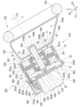
- FIG. 1 is a diagram illustrating a steering device according to a first embodiment.
- FIG. 2 is a partial cross-sectional view showing a part of the steering device in the first embodiment.
- FIG. 3 is a partial cross-sectional view showing a part of the steering device according to the second embodiment.
- FIG. 4 is a partial cross-sectional view showing a part of a steering device according to the third embodiment.
- FIG. 5 is a partial cross-sectional view showing a part of a steering device according to a fourth embodiment.
- FIG. 6 is a partial cross-sectional view showing a part of a steering device according to a fifth embodiment.
- the XYZ coordinate system is appropriately shown as a three-dimensional orthogonal coordinate system.
- the Z axis direction is the up-down direction.
- the side where the Z axis arrow points (+Z side) is the upper side, and the opposite side to the side where the Z axis arrow points (-Z side) is the lower side.
- the X axis direction is a direction perpendicular to the Z axis direction, and is the front-rear direction of the vehicle in which the steering device in the following embodiment is mounted.
- the side where the X axis arrow points (+X side) is the front side of the vehicle, and the opposite side to the side where the X axis arrow points (-X side) is the rear side of the vehicle.
- the Y axis direction is a direction perpendicular to both the X axis direction and the Z axis direction, and is the left-right direction of the vehicle, i.e., the vehicle width direction.
- the side where the Y axis arrow points (+Y side) is the left side of the vehicle, and the opposite side to the side where the Y axis arrow points (-Y side) is the right side of the vehicle.
- the Z axis direction is, for example, a vertical direction.
- the X-axis direction and the Y-axis direction are, for example, horizontal directions.
- a steering device 100 of this embodiment shown in Fig. 1 is mounted on a vehicle.
- the steering device 100 is a steer-by-wire type steering device.
- the steering device 100 includes a steering device 101 and a turning device 102.
- the steering device 101 includes a steering wheel 103 that is steered by a driver, and an actuator 10 that applies a force to the steering wheel 103.
- the turning device 102 includes a turning mechanism 90 and a turning-side actuator 107.
- the steering device 101 and the turning device 102 are not mechanically connected to each other.
- the turning device 102 is driven based on the steering angle ⁇ of the steering wheel 103.
- the steering mechanism 90 has a first steered wheel 94a, a second steered wheel 94b, a rack shaft 91, tie rods 92a, 92b, and knuckle arms 93a, 93b.
- the rack shaft 91 extends in the left-right direction of the vehicle, i.e., in the vehicle width direction.
- the first steered wheel 94a is connected to one end of the rack shaft 91 via the tie rod 92a and the knuckle arm 93a.
- the second steered wheel 94b is connected to the other end of the rack shaft 91 via the tie rod 92b and the knuckle arm 93b.
- the steering wheel 103 is rotated around the central axis J by the driver.
- the central axis J is a virtual axis. As shown in FIG. 2, in this embodiment, the central axis J extends in a direction inclined vertically with respect to the front-rear direction. The central axis J is positioned upward as it approaches the rear (-X side). The direction in which the central axis J extends is perpendicular to the left-right direction (Y-axis direction) of the vehicle.
- the axial direction in which the central axis J extends is simply referred to as the "axial direction.”
- the radial direction centered on the central axis J is simply referred to as the "radial direction”
- the circumferential direction centered on the central axis J is simply referred to as the “circumferential direction.”
- the rotation angle of the steering wheel 103 around the central axis J is the steering angle ⁇ .
- the direction in which the central axis J extends is indicated by an arrow D1.
- the side toward which arrow D1 points (+D1 side) is called “one axial side,” and the side opposite to the side toward which arrow D1 points (-D1 side) is called “the other axial side.”
- One axial side is the rear and upper side.
- the other axial side is the front (+X side) and lower side.
- the direction perpendicular to both the left-right direction (Y-axis direction) and the axial direction of the vehicle is indicated by arrow D2.
- the direction in which arrow D2 extends is called the "orthogonal direction”
- the side to which arrow D2 faces (+D2 side) is called “one side of the orthogonal direction”
- the side opposite to the side to which arrow D2 faces (-D2 side) is called “the other side of the orthogonal direction”.
- One side of the orthogonal direction is the upper and front side (+X side).
- the other side of the orthogonal direction is the lower and rear side (-X side).
- the steering wheel 103 has a base 104 and a wheel main body 105 fixed to the base 104.
- the base 104 has a storage section 104d. Although not shown in the figure, an airbag is stored inside the storage section 104d.
- the base 104 has an opposing wall section 104c located on the other axial side (-D1 side).
- the opposing wall section 104c is a wall section located on the other axial side among the walls constituting the storage section 104d.
- the base 104 has a connecting tube section 104b that protrudes to one axial side from a surface on one axial side (+D1 side) of the opposing wall section 104c.
- the surface on one axial side of the opposing wall section 104c constitutes part of the inner surface of the storage section 104d.
- the connecting tube section 104b is cylindrical, centered on the central axis J and opening to the other axial side.
- the opening on the other axial side of the connecting tube portion 104b opens to the surface on the other axial side of the opposing wall portion 104c.
- the actuator 10 is an actuator that generates a steering reaction force on the steering wheel 103 of a vehicle.
- the actuator 10 includes a motor 20, an adjustment mechanism 30, and a control device 40.
- the steering device 100 includes the motor 20, the adjustment mechanism 30, and the control device 40.
- the motor 20 generates a steering reaction force around the central axis J in the steering wheel 103 of the vehicle. As shown in FIG. 2, the motor 20 is located on the other axial side (-D1 side) of the steering wheel 103. No reduction mechanism is provided between the motor 20 and the steering wheel 103. This allows the steering device 101 to be made smaller in the axial direction than when a reduction mechanism is provided between the motor 20 and the steering wheel 103.
- the motor 20 includes a housing 50, a rotor 60, a stator 70, and a bearing 63.
- the housing 50 accommodates the rotor 60, the stator 70, and the bearing 63 inside.
- the housing 50 includes a lid portion 51, a cylindrical portion 52, a bottom portion 53, and a bearing holder 54.
- the motor 20 includes a lid portion 51, a cylindrical portion 52, a bottom portion 53, and a bearing holder 54.
- the lid portion 51, the tubular portion 52, the bottom portion 53, and the bearing holder 54 may be separate from one another. Also, two or three of the lid portion 51, the tubular portion 52, the bottom portion 53, and the bearing holder 54 may be part of the same single member, and the remaining portions of the lid portion 51, the tubular portion 52, the bottom portion 53, and the bearing holder 54 may be separate from the single member.
- the bearing retaining portion 54 is provided on the radial inner edge of the lid portion 51.
- the bearing retaining portion 54 protrudes from the lid portion 51 to one axial side (+D1 side).
- the bearing retaining portion 54 is cylindrical with the center on the central axis J.
- the bearing retaining portion 54 has a peripheral wall portion 54a that protrudes from the radial inner edge of the lid portion 51 to one axial side, and an annular wall portion 54b that protrudes radially inward from the end of the peripheral wall portion 54a on one axial side.
- the annular wall portion 54b is annular with the center on the central axis J.
- the rotor 60 can rotate around the central axis J.
- the rotor 60 has a motor shaft 61 and a rotor body 62.
- the motor shaft 61 extends in the axial direction of the central axis J.
- the motor shaft 61 is generally cylindrical with the central axis J as its center.
- the motor shaft 61 passes axially through the radial inside of the cover portion 51 and the radial inside of the bearing holder 54.
- the end of the motor shaft 61 on one axial side (+D1 side) is located axially further to the one axial side than the bearing holder 54 and is located outside the housing 50.
- the motor shaft 61 is directly connected to the steering wheel 103. Therefore, compared to when the motor shaft 61 and the steering wheel 103 are connected via a steering shaft and a reduction mechanism, the steering device 101 can be made smaller in the axial direction by the amount that a steering shaft and a reduction mechanism are not provided.
- the motor shaft 61 instead of providing a steering shaft connected to the steering wheel 103, the motor shaft 61 is directly connected to the steering wheel 103.
- the structure in which the motor shaft 61 is directly connected to the steering wheel 103 can also be said to be a structure in which the motor shaft 61 doubles as a steering shaft.
- no steering shaft is provided separately from the motor shaft 61, and no connecting member is required to connect the motor shaft 61 and the steering shaft. Therefore, according to this embodiment, compared to when the motor shaft 61 is connected to the steering shaft, the steering device 101 can be made smaller in the axial direction.
- the motor shaft 61 is fitted and fixed in the connecting hole portion 104a, i.e., the connecting tube portion 104b. More specifically, one axial end (+D1 side) of the motor shaft 61 is fitted and fixed in the connecting hole portion 104a, i.e., the connecting tube portion 104b.
- the method of fixing the motor shaft 61 to the steering wheel 103 is not particularly limited.
- the motor shaft 61 may be fixed to the steering wheel 103 by being pressed into the connecting hole portion 104a, may be fixed to the steering wheel 103 by a screw, or may be fixed to the steering wheel 103 by an adhesive.
- the rotor body 62 is fixed to the motor shaft 61.
- the rotor body 62 has a rotor core 62c, a first magnet 62d, and a second magnet 62e.
- the rotor core 62c is fixed to the outer peripheral surface of the motor shaft 61.
- the rotor core 62c is annular about the central axis J.
- the rotor core 62c is plate-shaped with its plate surface facing the axial direction.
- the first magnet 62d is fixed to a surface on one axial side (+D1 side) of the rotor core 62c.
- the second magnet 62e is fixed to a surface on the other axial side (-D1 side) of the rotor core 62c.
- the first magnet 62d and the second magnet 62e are annular surrounding the central axis J.
- the first magnet 62d and the second magnet 62e are plate-shaped with their plate surface facing the axial direction.
- the radial inner edge of the first magnet 62d and the radial inner edge of the second magnet 62e are disposed radially outwardly away from the outer circumferential surface of the motor shaft 61.
- the magnetic poles of the first magnet 62d and the magnetic poles of the second magnet 62e each include multiple N poles and multiple S poles that are alternately arranged around the central axis J.
- the stator 70 faces the rotor 60 across a gap.
- the stator 70 is disposed axially opposite the rotor 60. More specifically, the stator 70 is disposed axially opposite the rotor body 62.
- the motor 20 is an axial gap type motor in which the rotor 60 and the stator 70 face each other across an axial gap.
- the stator 70 is disposed axially opposite the rotor body 62, and the motor shaft 61 is directly connected to the steering wheel 103, so that the torque of the motor 20 can be increased while the steering device 101 is suitably downsized in the axial direction. Also, in this embodiment, the stator 70 is disposed axially opposite the rotor 60, and no reduction mechanism is provided between the motor 20 and the steering wheel 103, so that the torque of the motor 20 can be increased while the steering device 101 is suitably downsized in the axial direction.
- the stator 70 is annular and surrounds the motor shaft 61. More specifically, the stator 70 is substantially annular and centered on the central axis J.
- the stator 70 is fixed to the inner circumferential surface of the tubular portion 52. More specifically, the radially outer surface of the stator 70 is fixed to the inner circumferential surface of the tubular portion 52.
- the method of fixing the stator 70 to the tubular portion 52 is not particularly limited.
- the stator 70 may be fixed to the tubular portion 52 by press-fitting, by shrink fitting, or by screws, adhesive, or the like.
- the stator 70 has a stator core 73 and a coil 74. In this embodiment, a plurality of stator cores 73 and coils 74 are provided at intervals in the circumferential direction.
- the plurality of coils 74 are attached to the plurality of stator cores 73, respectively. Each coil 74 is attached to each stator core 73, for example, via an insulator not shown.
- the stator 70 includes a first stator 71 and a second stator 72.
- the first stator 71 is located on one axial side (+D1 side) of the rotor body 62.
- the second stator 72 is located on the other axial side (-D1 side) of the rotor body 62.
- the rotating parts provided in the motor 20 can be made smaller and the structure of the motor 20 can be simplified compared to an axial gap type motor in which two rotor bodies 62 are provided for one stator 70.
- the first stator 71 is annular and surrounds a portion of the motor shaft 61 located on one axial side (+D1 side) of the rotor body 62.
- the second stator 72 is annular and surrounds a portion of the motor shaft 61 located on the other axial side (-D1 side) of the rotor body 62.
- the first stator 71 and the second stator 72 sandwich the rotor body 62 in the axial direction.
- the stator core 73 of the first stator 71 faces the first magnet 62d of the rotor body 62 in the axial direction with a gap therebetween.
- the stator core 73 of the second stator 72 faces the second magnet 62e of the rotor body 62 in the axial direction with a gap therebetween.
- the motor 20 has a conductive part 74a electrically connected to the stator 70.
- the conductive part 74a extends radially outward from the stator 70 and is connected to the substrate 41 described below.
- the conductive part 74a is a coil lead wire drawn radially outward from the coil 74.
- the conductive part 74a which is a coil lead wire, is formed by the end of the conductor that constitutes the coil 74.
- the conductive part 74a may be a bus bar electrically connected to the coil 74.
- the conductive part 74a includes a plurality of conductive parts 74a extending radially outward from the first stator 71 and a plurality of conductive parts 74a extending radially outward from the second stator 72.
- the bearing 63 rotatably supports the rotor 60.
- the bearing 63 is a rolling bearing. More specifically, the bearing 63 is a ball bearing.
- the bearing 63 includes a first bearing 63a and a second bearing 63b. That is, the motor 20 includes the first bearing 63a and the second bearing 63b.
- the first bearing 63a rotatably supports a portion of the motor shaft 61 located on one axial side (+D1 side) of the rotor body 62.
- the second bearing 63b rotatably supports a portion of the motor shaft 61 located on the other axial side (-D1 side) of the rotor body 62.
- the first bearing 63a is located on one axial side of the stator 70.
- the second bearing 63b is located on the other axial side of the stator 70.
- the first bearing 63a is held inside the bearing holder 54.
- the first bearing 63a is supported from one axial side by the annular wall portion 54b.
- the second bearing 63b is held in a bearing holder 55 housed inside the housing 50.
- the bearing holder 55 is annular and surrounds the motor shaft 61.
- the radial outer edge of the bearing holder 55 is fixed to the inner peripheral surface of the cylindrical portion 52.
- the bearing holder 55 is located on the other axial side of the two stators 70.
- the bearing holder 55 is disposed opposite the other axial side of the second stator 72 with a gap between them.
- the control device 40 controls the motor 20.
- the control device 40 is electrically connected to the stator 70.
- the control device 40 is located radially outside the motor 20. Therefore, the steering device 101 can be made smaller in the axial direction than when the control device 40 is located axially of the motor 20.
- the space radially outside the motor 20 is less likely to be used for arranging other parts, and is more likely to be empty space, compared to the space radially outside the adjustment mechanism 30. Therefore, by using the space radially outside the motor 20 as the space for arranging the control device 40, the space within the vehicle can be effectively utilized.
- control device 40 is located on the other orthogonal side (-D2 side) of the housing 50.
- the control device 40 has a substrate 41 and a case 42.
- the case 42 is fixed to the surface of the housing 50 on the other orthogonal side.
- the case 42 is box-shaped and opens on one side in the orthogonal direction (+D2 side).
- the plate surface of the substrate 41 faces in the radial direction. Therefore, the control device 40 can be made smaller in the radial direction compared to when the plate surface of the substrate 41 faces in the axial direction. This allows the steering device 101 to be made smaller in the radial direction.
- the plate surface of the substrate 41 faces in the orthogonal direction (D2 axis direction).
- the substrate 41 is housed inside the case 42. In this embodiment, the substrate 41 is fixed to the case 42.
- a conductive portion 74a is connected to the substrate 41.
- the substrate 41 is electrically connected to the coil 74 of the stator 70 via the conductive portion 74a.
- the substrate 41 is electrically connected to both the first stator 71 and the second stator 72 via the conductive portion 74a.
- the conductive portion 74a extending radially outward from the coil 74 of the first stator 71 is connected to the substrate 41 through a through hole 52c provided in the cylindrical portion 52.
- the conductive portion 74a extending radially outward from the coil 74 of the second stator 72 is connected to the substrate 41 through a through hole 52d provided in the cylindrical portion 52.
- the conductive portion 74a extends radially outward from the stator 70 and is connected to the substrate 41, so that the substrate 41 and the stator 70, whose plate surfaces face radially, can be easily connected to each other.
- the substrate 41 is provided with an inverter circuit that supplies power to the stator 70. Power is supplied from the inverter circuit provided on the substrate 41 to the coil 74 of the stator 70 via the conductive portion 74a, thereby driving the motor 20.
- the actuator 10 is equipped with a rotation detection device 80 capable of detecting the rotation angle of the rotor 60.
- the rotation detection device 80 is accommodated inside the housing 50.
- the rotation detection device 80 is located inside the housing 50, axially between the bearing holder 55 and the bottom 53.
- the rotation detection device 80 has a sensor board 81, a rotation sensor 82, and a sensor magnet 83.
- the plate surface of the sensor board 81 faces the axial direction.
- the sensor board 81 is fixed to the bottom 53.
- the sensor board 81 is electrically connected to the board 41 by a wiring 84.
- the wiring 84 extends from inside the case 42 through a through hole 52e provided in the tube portion 52 to inside the housing 50.
- the rotation sensor 82 is attached to the surface of one axial side (+D1 side) of the sensor board 81.
- the rotation sensor 82 is a magnetic sensor.
- the rotation sensor 82 may be a magnetoresistance effect element, i.e., an MR (Magneto Resistive) sensor, or a Hall element.
- the rotation sensor 82 may be any type of sensor that can detect the rotation of the rotor 60.
- the sensor magnet 83 is fixed to the rotor 60. In this embodiment, the sensor magnet 83 is fixed to the end face of the motor shaft 61 on the other axial side (-D1 side).
- the sensor magnet 83 is disk-shaped with the central axis J as its center. The sensor magnet 83 faces the rotation sensor 82 with a gap in the axial direction.
- the rotation sensor 82 can detect the rotation angle of the rotor 60 by detecting the magnetic field of the sensor magnet 83.
- the motor 20 has a torque sensor 85.
- the torque sensor 85 is a sensor capable of detecting torque around the central axis J generated in the motor shaft 61.
- the torque sensor 85 is, for example, a strain gauge.
- the torque sensor 85 is attached to the outer peripheral surface of the motor shaft 61. In this embodiment, the torque sensor 85 is attached to the outer peripheral surface of a portion of the motor shaft 61 located on one axial side (+D1 side) of the rotor body 62.
- the torque sensor 85 may be attached to any location on the motor shaft 61 as long as it can detect torque around the central axis J generated in the motor shaft 61.
- the torque sensor 85 may be any type of sensor as long as it can detect torque around the central axis J generated in the motor shaft 61.
- the control device 40 determines a target value of the steering reaction force to be generated in the steering wheel 103 based on the output from the rotation sensor 82 and the torque sensor 85, and controls the motor 20 based on the target value.
- the control device 40 detects the steering angle ⁇ of the steering wheel 103 based on the output from the rotation sensor 82 and the torque sensor 85, and sends a signal to the steering side control device 108 based on the steering angle ⁇ .
- the adjustment mechanism 30 can adjust the position of the steering wheel 103.
- the adjustment mechanism 30 has, for example, a telescopic mechanism that can adjust the position of the steering wheel 103 in the axial direction (D1 axis direction), and a tilt mechanism that can adjust the angle of the steering wheel 103 relative to the horizontal direction.
- the tilt mechanism can adjust the position of the steering wheel 103 in the up-down direction (Z axis direction) by changing the angle of the central axis J relative to the horizontal direction.
- the adjustment mechanism 30 is located on the other axial side (-D1 side) of the motor 20.
- the adjustment mechanism 30 is fixed to the housing 50 of the motor 20.
- the motor 20 is arranged between the steering wheel 103 and the adjustment mechanism 30 in the axial direction.
- the adjustment mechanism 30 needs to have the motor shaft 61 pass through it in the axial direction, or the adjustment mechanism 30 needs to be connected to the motor shaft 61, etc., which may cause problems such as an increase in the number of parts of the adjustment mechanism 30 and a complication of the connection structure of the adjustment mechanism 30.
- the motor 20 is arranged between the steering wheel 103 and the adjustment mechanism 30 in the axial direction. Therefore, there is no need to pass the motor shaft 61 through the adjustment mechanism 30 in the axial direction, and there is no need to connect the adjustment mechanism 30 to the motor shaft 61.
- This makes it possible to suppress an increase in the number of parts of the adjustment mechanism 30 and to suppress a complication of the connection structure of the adjustment mechanism 30. This makes it easier to miniaturize the adjustment mechanism 30 and the steering device 101, making it easier to miniaturize the steering device 101 in the axial direction.
- the adjustment mechanism 30 can adjust the position of the steering wheel 103 by moving the position of the motor 20 connected to the steering wheel 103. Therefore, the adjustment mechanism 30 can adjust the position of the steering wheel 103 together with the motor 20. This makes it possible to easily adjust the position of the steering wheel 103 by the adjustment mechanism 30. Also, compared to a case where the position of the steering wheel 103 is adjusted without moving the position of the motor 20, it is easier to prevent the structure of the adjustment mechanism 30 from becoming complicated. Therefore, it is easier to make the adjustment mechanism 30 more compact, and it is easier to make the steering device 101 more compact in the axial direction.
- the tubular portion 252 of the housing 250 of the motor 220 is tubular and opens on both axial ends. Therefore, it is easier to reduce the size of the housing 250 in the axial direction compared to a case where the housing 250 is provided with portions that close both axial ends of the tubular portion 252. This makes it easier to reduce the size of the steering device 201 in the axial direction.
- the housing 250 does not have a cover portion 51 and a bottom portion 53. In this embodiment, the housing 250 is made of the tubular portion 252.
- the cylindrical portion 252 has a small diameter portion 252a and a large diameter portion 252b.
- the end of the small diameter portion 252a on one axial side (+D1 side) is the end of the cylindrical portion 252 on one axial side.
- the first stator 71 and the second stator 72 are fixed to the inner peripheral surface of the small diameter portion 252a.
- the end face of the small diameter portion 252a on one axial side i.e., the end face of the cylindrical portion 252 on one axial side, is provided at the same axial position as the end face of the first stator 71 on one axial side.
- the large diameter portion 252b is connected to the end of the small diameter portion 252a on the other axial side (-D1 side).
- the end of the large diameter portion 252b on the other axial side is the end of the cylindrical portion 252 on the other axial side.
- the inner diameter of the large diameter portion 252b is larger than the inner diameter of the small diameter portion 252a.
- the outer diameter of the large diameter portion 252b is larger than the outer diameter of the small diameter portion 252a.
- the axial dimension of the large diameter portion 252b is smaller than the axial dimension of the small diameter portion 252a.
- a step portion 252d having a step surface 252c facing one axial side is provided between the outer circumferential surface of the small diameter portion 252a and the outer circumferential surface of the large diameter portion 252b.
- the step surface 252c is annular about the central axis J.
- the cylindrical portion 252 is cylindrical with an opening 252e that opens on the axial side where the adjustment mechanism 230 is located, i.e., on the other axial side (-D1 side).
- the opening 252e is an opening on the other axial side of the large diameter portion 252b.
- the opening 252e is blocked by the adjustment mechanism 230. In this way, by configuring the opening 252e to be blocked by the adjustment mechanism 230, the adjustment mechanism 230 can be brought closer to the motor 220 in the axial direction. This allows the steering device 201 to be made more compact in the axial direction.
- the adjustment mechanism housing 231 of the adjustment mechanism 230 has a top wall portion 232, a peripheral wall portion 233, and a fitting portion 234.
- the top wall portion 232 is disk-shaped and centered on the central axis J. One axial side (+D1 side) surface of the top wall portion 232 faces the inside of the housing 250.
- a sensor board 281 of the rotation detection device 280 is fixed to one axial side surface of the top wall portion 232.
- the rotation detection device 280 is similar to the rotation detection device 80 in the first embodiment, except that the sensor board 281 is fixed to the top wall portion 232.
- the peripheral wall portion 233 extends from the radial outer edge of the top wall portion 232 to the other axial side (-D1 side).
- the fitting portion 234 protrudes from the top wall portion 232 to one axial side (+D1 side).
- the fitting portion 234 is cylindrical with its center on the central axis J.
- the fitting portion 234 is fitted into the radial inner side of the large diameter portion 252b. In other words, the fitting portion 234 is fitted into the opening 252e.
- the adjustment mechanism 230 can be attached to the housing 250 with good axial accuracy while blocking the opening 252e of the tube portion 252 with the adjustment mechanism 230. Furthermore, by configuring the tube portion 252 to have an opening 252e, it is possible to couple the adjustment mechanism 230 to the motor 220 without using a screw member by fitting it into the opening 252e as described above, but it is also possible to fix the adjustment mechanism 230 to the motor 220 using a screw member. In this way, according to this embodiment, the degree of freedom of the structure that can be adopted to fix the adjustment mechanism 230 to the motor 220 can be improved. Furthermore, since a structure that is easy to assemble can be adopted to fix the adjustment mechanism 230 to the motor 220 in accordance with the structure of the adjustment mechanism 230, the assembly of the actuator 210 can be improved.
- the motor 220 does not have the bearing holder 55 of the first embodiment.
- the motor 220 includes a first bearing retaining member 256 and a second bearing retaining member 257.
- the first bearing retaining member 256 is located radially inside the first stator 71.
- the first bearing retaining member 256 is fixed to the first stator 71.
- the second bearing retaining member 257 is located radially inside the second stator 72.
- the second bearing retaining member 257 is fixed to the second stator 72.
- the first bearing retaining member 256 and the second bearing retaining member 257 are axially symmetrical to each other.
- the material constituting the first bearing retaining member 256 and the material constituting the second bearing retaining member 257 are non-magnetic.
- the first bearing retaining member 256 has a first peripheral wall portion 256a surrounding the central axis J, and a first annular wall portion 256b protruding radially inward from an end portion on one axial side (+D1 side) of the first peripheral wall portion 256a.
- the first peripheral wall portion 256a is cylindrical and has a center on the central axis J and opens to the other axial side (-D1 side).
- the first peripheral wall portion 256a is fitted to the radial inner side of the first stator 71.
- the outer peripheral surface of the first peripheral wall portion 256a contacts the radial inner surface of the stator core 73 of the first stator 71.
- the first peripheral wall portion 256a is fixed to, for example, the stator core 73.
- the axial dimension of the first peripheral wall portion 256a is the same as the axial dimension of the first stator 71.
- the first annular wall portion 256b is annular and surrounds the motor shaft 61.
- the first annular wall portion 256b is annular and centered on the central axis J.
- the second bearing retaining member 257 has a second peripheral wall portion 257a surrounding the central axis J, and a second annular wall portion 257b protruding radially inward from the end of the second peripheral wall portion 257a on the other axial side (-D1 side).
- the second peripheral wall portion 257a is cylindrical with the central axis J as its center and opening on one axial side (+D1 side).
- the second peripheral wall portion 257a is fitted to the radial inner side of the second stator 72.
- the outer peripheral surface of the second peripheral wall portion 257a contacts the radial inner surface of the stator core 73 of the second stator 72.
- the second peripheral wall portion 257a is fixed to, for example, the stator core 73.
- the axial dimension of the second peripheral wall portion 257a is the same as the axial dimension of the second stator 72.
- the second annular wall portion 257b is annular and surrounds the motor shaft 61.
- the second annular wall portion 257b is annular and centered on the central axis J.
- the bearing 263 includes a first bearing 263a and a second bearing 263b.
- the first bearing 263a is a bearing 263 that rotatably supports a portion of the motor shaft 61 that is located on one axial side (+D1 side) of the rotor body 62.
- the second bearing 263b is a bearing 263 that rotatably supports a portion of the motor shaft 61 that is located on the other axial side (-D1 side) of the rotor body 62.
- At least a portion of the first bearing 263a is located radially inside the first stator 71.
- At least a portion of the second bearing 263b is located radially inside the second stator 72. Therefore, at least a portion of each of the two bearings 263 can be disposed radially inside the stator 70. This allows the motor 220 to be made smaller in the axial direction, and the steering device 201 to be made smaller in the axial direction.
- the entire first bearing 263a is located radially inside the first stator 71.
- the entire second bearing 263b is located radially inside the second stator 72. Therefore, the entire two bearings 263 can be arranged radially inside the stator 70. This allows the motor 220 to be made smaller in the axial direction, and the steering device 201 to be made smaller in the axial direction.
- the first bearing 263a is held by the first bearing retaining member 256.
- the second bearing 263b is held by the second bearing retaining member 257. Therefore, each bearing 263 can be stably arranged radially inside each stator 70.
- the position of the stator 70 and the relative positional relationship between the stator 70 and the rotor body 62 can be determined by adjusting the axial position and spacing between the rotor body 62 and the first bearing 263a and the second bearing 263b. This also makes it easier to optimize the air gap between the rotor body 62 and the stator 70 in the axial direction.
- the first bearing 263a is supported from one axial side (+D1 side) by the first annular wall portion 256b.
- the second bearing 263b is supported from the other axial side (-D1 side) by the second annular wall portion 257b.
- the other configurations of the bearing 263 are similar to the other configurations of the bearing 63 in the first embodiment.
- the other configurations of the motor 220 are similar to the other configurations of the motor 20 in the first embodiment.
- the end of the control device 240 on the other axial side contacts the step surface 252c.
- the rest of the configuration of the control device 240 is similar to the rest of the configuration of the control device 40 in the first embodiment.
- the other configurations of the actuator 210 are similar to the other configurations of the actuator 10 in the first embodiment.
- the other configurations of the steering device 201 are similar to the other configurations of the steering device 101 in the first embodiment.
- the housing 350 of the motor 320 has a bottom member 353.
- the bottom member 353 closes the opening 252e on the other axial side (-D1 side) of the cylindrical portion 352.
- the cylindrical portion 352 is similar to the cylindrical portion 252 of the second embodiment, except that the small diameter portion 352a does not have the through holes 52c, 52d, and 52e.
- the bottom member 353 is fixed to the cylindrical portion 352.
- the bottom member 353 has a bottom wall portion 353a that closes the opening 252e, and a fitting portion 353b that protrudes from the bottom wall portion 353a to one axial side (+D1 side).
- the fitting portion 353b is annular about the central axis J. The fitting portion 353b is fitted into the opening 252e.
- the motor 320 has a portion located radially outward from the adjustment mechanism 330.
- the radial dimension of the adjustment mechanism 330 is smaller than the radial dimension of the adjustment mechanism 30 in the first embodiment.
- at least a portion of the control device 340 is located radially outward from the adjustment mechanism 330 and overlaps in the axial direction with a portion of the motor 320 located radially outward from the adjustment mechanism 330. Therefore, the actuator 310 can be made smaller in the axial direction than when the control device 340 is arranged axially next to the motor 320 or the adjustment mechanism 330. This allows the steering device 301 to be made smaller in the axial direction.
- control device 340 can be arranged in the step portion generated between the motor 320 and the adjustment mechanism 330, the actuator 310 can be prevented from becoming larger in the radial direction. Therefore, the steering device 301 can be prevented from becoming larger in the radial direction.
- the entire control device 340 is located radially outward of the adjustment mechanism 330, and overlaps in the axial direction with a portion of the motor 320 that is located radially outward of the adjustment mechanism 330. This allows the actuator 310 to be made smaller in the axial and radial directions.
- the other configurations of the motor 320 are similar to the other configurations of the motor 220 in the second embodiment.
- the control device 340 is located on one side of the adjustment mechanism 330 in the orthogonal direction (+D2 side).
- the control device 340 is fixed to a surface on the other axial side (-D1 side) of a portion of the motor 320 located on one side of the adjustment mechanism 330 in the orthogonal direction.
- the control device 340 is fixed to the bottom wall portion 353a.
- the plate surface of the substrate 341 of the control device 340 faces in the radial direction.
- the plate surface of the substrate 341 faces in the orthogonal direction (D2 axial direction).
- the case 342 that houses the substrate 341 inside is fixed to a portion of the bottom wall portion 353a that is located radially outward of the adjustment mechanism 330.
- the case 342 is fixed to a portion of the bottom wall portion 353a that is located on one side of the adjustment mechanism 330 in the orthogonal direction.
- the substrate 341 is electrically connected to the coils 74 of the first stator 71 and the coils 74 of the second stator 72 by a plurality of conductive parts 374a passing through through holes 353c provided in the bottom wall portion 353a.
- the substrate 341 is electrically connected to the sensor substrate 81 via wiring 384 passing through the through holes 353c.
- the sensor substrate 81 is fixed to a surface on one axial side (+D1 side) of the bottom wall portion 353a.
- the other configurations of the actuator 310 are similar to the other configurations of the actuator 210 in the second embodiment.
- the other configurations of the steering device 301 are similar to the other configurations of the steering device 201 in the second embodiment.
- the rotor body 462 includes a first rotor body 462a and a second rotor body 462b.
- the first rotor body 462a is located on one axial side (+D1 side) of the stator 470.
- the second rotor body 462b is located on the other axial side (-D1 side) of the stator 470.
- the motor 420 an axial gap type motor in which two rotor bodies 462 are provided for one stator 470, the torque density can be increased compared to the case of an axial gap type motor in which two stators 470 are provided for one rotor body 462.
- the first rotor body 462a and the second rotor body 462b sandwich the stator 470 in the axial direction.
- the first rotor body 462a and the second rotor body 462b are similar to the rotor body 62 in the first embodiment, except that their axial positions are different.
- the control device 440 is similar to the control device 40 in the first embodiment, except that the substrate 41 is electrically connected to the coil 74 of one of the stators 470.
- the other configurations of the motor 420 are similar to the other configurations of the motor 20 in the first embodiment.
- the other configurations of the actuator 410 are similar to the other configurations of the actuator 10 in the first embodiment.
- the other configurations of the steering device 401 are similar to the other configurations of the steering device 101 in the first embodiment.
- the motor 520 includes two rotor bodies 462 and one stator 470, as in the fourth embodiment.
- the motor 520 is not provided with the bearing holder 55 in the first embodiment.
- the motor 520 includes a second bearing holding member 557.
- the second bearing holding member 557 is located radially inside the stator 470.
- the structure of the second bearing holding member 557 is the same as that of the second bearing holding member 257 in the second embodiment.
- the second bearing holding member 557 includes a cylindrical second peripheral wall portion 557a that opens on one axial side (+D1 side), and a second annular wall portion 557b that protrudes radially inward from the end of the second peripheral wall portion 557a on the other axial side (-D1 side).
- the second bearing 563b is held by the second bearing holding member 557. At least a portion of the second bearing 563b is located radially inside the stator 470. More specifically, the entire second bearing 563b is located radially inside the stator 470. That is, in this embodiment, of the first bearing 63a and the second bearing 563b, only the second bearing 563b is located radially inside the stator 470, and the first bearing 63a is arranged axially offset relative to the stator 470. Even in this case, the steering device 501 can be made smaller in the axial direction than when both the first bearing 63a and the second bearing 563b are arranged axially offset relative to the stator 470.
- the other configurations of the second bearing 563b are similar to the other configurations of the second bearing 263b in the second embodiment.
- the rest of the configuration of the motor 520 is similar to the rest of the configuration of the motor 420 in the fourth embodiment.
- the rest of the configuration of the actuator 510 is similar to the rest of the configuration of the actuator 410 in the fourth embodiment.
- the rest of the configuration of the steering device 501 is similar to the rest of the configuration of the steering device 401 in the fourth embodiment.
- the present invention is not limited to the above-described embodiment, and other configurations and methods may be adopted within the scope of the technical concept of the present invention.
- the number of bearings that rotatably support the motor shaft is not particularly limited as long as it is one or more.
- the type of bearing is not particularly limited. When a first bearing and a second bearing are provided, only a portion of each of the first bearing and the second bearing may be located radially inside the stator. The first bearing and the second bearing may be directly held by the stator without a bearing holding member. At least a portion of the first bearing and at least a portion of the second bearing may be located radially inside the same stator.
- the control device may be provided in any position.
- the adjustment mechanism may be any mechanism that can adjust the position of the steering wheel.
- the adjustment mechanism may have only one of the telescopic mechanism and the tilt mechanism described above.
- the central axis may extend in any direction.
- the motor and the steering wheel may be connected to each other in any manner.
- a steering shaft may be connected to the steering wheel, and the motor shaft of the motor may be connected to the steering shaft.
- the actuator described in (1) including an adjustment mechanism capable of adjusting a position of the steering wheel, the motor being disposed axially between the steering wheel and the adjustment mechanism on the central axis.
- the actuator described in (2) in which the adjustment mechanism is capable of adjusting the position of the steering wheel by moving the position of the motor connected to the steering wheel.
- the actuator according to (2) or (3) further comprising a control device electrically connected to the stator, the motor having a portion located radially outward from the adjustment mechanism, and at least a portion of the control device located radially outward from the adjustment mechanism and overlapping in the axial direction with a portion of the motor located radially outward from the adjustment mechanism.
- the actuator according to any one of (2) to (4) further comprising a tubular portion for holding the stator therein, the tubular portion being tubular with an opening that opens on the axial side where the adjustment mechanism is located, and the opening is blocked by the adjustment mechanism.
- a steer-by-wire type steering device mounted on a vehicle, the steering device having a steering wheel and an actuator described in any one of (1) to (7) that applies a force to the steering wheel, and a turning device that is driven based on the steering angle of the steering wheel.
Landscapes
- Engineering & Computer Science (AREA)
- Chemical & Material Sciences (AREA)
- Combustion & Propulsion (AREA)
- Transportation (AREA)
- Mechanical Engineering (AREA)
- Power Steering Mechanism (AREA)
Abstract
本発明のアクチュエータの一つの態様は、車両に搭載されるステアバイワイヤ方式のステアリング装置に備えられ、車両のステアリングホイールに操舵反力を発生させるアクチュエータであって、ステアリングホイールに中心軸線周りの操舵反力を発生させるモータを備える。モータは、ロータおよびステータを有する。ステータは、ロータと軸方向に対向して配置される。本発明のアクチュエータにおいて、モータとステアリングホイールとの間には減速機構が設けられない。
Description
本発明は、アクチュエータ、およびステアリング装置に関する。
従来、操舵装置と転舵装置とが互いに機械的に連結されない分離型パワーステアリング装置、いわゆるステアバイワイヤ方式のステアリング装置が知られる(例えば、特許文献1)。
上記のようなステアリング装置においては、操舵装置を小型化することが望まれていた。
本発明は、上記事情に鑑みて、操舵装置を小型化できるアクチュエータ、およびステアリング装置を提供することを目的の一つとする。
本発明のアクチュエータの一つの態様は、車両に搭載されるステアバイワイヤ方式のステアリング装置に備えられ、前記車両のステアリングホイールに操舵反力を発生させるアクチュエータであって、前記ステアリングホイールに中心軸線周りの操舵反力を発生させるモータを備える。前記モータは、ロータおよびステータを有する。前記ステータは、前記ロータと軸方向に対向して配置される。前記モータと前記ステアリングホイールとの間には減速機構は設けられていない。
本発明のステアリング装置の一つの態様は、車両に搭載されるステアバイワイヤ方式のステアリング装置であって、ステアリングホイールおよび前記ステアリングホイールに力を加える上記のアクチュエータを有する操舵装置と、前記ステアリングホイールの操舵角に基づいて駆動される転舵装置と、を備える。
本発明の一つの態様によれば、ステアリング装置において、操舵装置を小型化できる。
図面においては、適宜3次元直交座標系としてXYZ座標系を示す。XYZ座標系において、Z軸方向は、上下方向である。Z軸の矢印が向く側(+Z側)は、上側であり、Z軸の矢印が向く側と逆側(-Z側)は、下側である。X軸方向は、Z軸方向と直交する方向であって、以下の実施形態におけるステアリング装置が搭載される車両の前後方向である。以下の実施形態において、X軸の矢印が向く側(+X側)は、車両における前側であり、X軸の矢印が向く側と逆側(-X側)は、車両における後側である。Y軸方向は、X軸方向とZ軸方向との両方と直交する方向であって、車両の左右方向、すなわち車幅方向である。以下の実施形態において、Y軸の矢印が向く側(+Y側)は、車両における左側であり、Y軸の矢印が向く側と逆側(-Y側)は、車両における右側である。Z軸方向は、例えば、鉛直方向である。X軸方向およびY軸方向は、例えば、水平方向である。
<第1実施形態>
図1に示す本実施形態のステアリング装置100は、車両に搭載される。ステアリング装置100は、ステアバイワイヤ方式のステアリング装置である。図1に示すように、ステアリング装置100は、操舵装置101と、転舵装置102と、を備える。操舵装置101は、操舵者によって操舵されるステアリングホイール103と、ステアリングホイール103に力を加えるアクチュエータ10と、を有する。転舵装置102は、転舵機構90と、転舵側アクチュエータ107と、を有する。操舵装置101と転舵装置102とは、互いに機械的に連結されていない。転舵装置102は、ステアリングホイール103の操舵角θに基づいて駆動される。
図1に示す本実施形態のステアリング装置100は、車両に搭載される。ステアリング装置100は、ステアバイワイヤ方式のステアリング装置である。図1に示すように、ステアリング装置100は、操舵装置101と、転舵装置102と、を備える。操舵装置101は、操舵者によって操舵されるステアリングホイール103と、ステアリングホイール103に力を加えるアクチュエータ10と、を有する。転舵装置102は、転舵機構90と、転舵側アクチュエータ107と、を有する。操舵装置101と転舵装置102とは、互いに機械的に連結されていない。転舵装置102は、ステアリングホイール103の操舵角θに基づいて駆動される。
転舵機構90は、第1転舵輪94aと、第2転舵輪94bと、ラック軸91と、タイロッド92a,92bと、ナックルアーム93a,93bと、を有する。ラック軸91は、車両の左右方向、すなわち車幅方向に延びる。第1転舵輪94aは、ラック軸91の一端部にタイロッド92aおよびナックルアーム93aを介して接続される。第2転舵輪94bは、ラック軸91の他端部にタイロッド92bおよびナックルアーム93bを介して接続される。
転舵側アクチュエータ107は、転舵側制御装置108と、転舵側モータ109と、を有する。転舵側制御装置108は、後述する制御装置40からの信号に基づいて転舵側モータ109を制御する。転舵側モータ109は、ラック軸91に接続される。転舵側モータ109は、ラック軸91を介して転舵機構90を駆動する。転舵側モータ109によって転舵機構90が駆動されることによって、第1転舵輪94aの角度および第2転舵輪94bの角度が変えられ、車両の進行方向が変化する。第1転舵輪94aおよび第2転舵輪94bは、車両におけるフロント側の一対のタイヤである。第1転舵輪94aの角度および第2転舵輪94bの角度は、実舵角である。
ステアリングホイール103は、操舵者によって中心軸線J周りに回転させられる。中心軸線Jは、仮想軸線である。図2に示すように、本実施形態において中心軸線Jは、前後方向に対して上下方向に傾いた方向に延びる。中心軸線Jは、後側(-X側)に向かうに従って上側に位置する。中心軸線Jが延びる方向は、車両の左右方向(Y軸方向)と直交する。以下の説明においては、特に断りのない限り、中心軸線Jが延びる軸方向を単に「軸方向」と呼ぶ。また、中心軸線Jを中心とする径方向を単に「径方向」と呼び、中心軸線Jを中心とする周方向を単に「周方向」と呼ぶ。ステアリングホイール103の中心軸線J周りの回転角度は、操舵角θである。図面においては、中心軸線Jが延びる方向を矢印D1で示す。矢印D1が向く側(+D1側)を「軸方向一方側」と呼び、矢印D1が向く側と逆側(-D1側)を「軸方向他方側」と呼ぶ。軸方向一方側は、後側かつ上側である。軸方向他方側は、前側(+X側)かつ下側である。
図面には、車両の左右方向(Y軸方向)および軸方向の両方と直交する方向を、矢印D2で示す。以下の説明においては、矢印D2が延びる方向を「直交方向」と呼び、矢印D2が向く側(+D2側)を「直交方向一方側」と呼び、矢印D2が向く側と逆側(-D2側)を「直交方向他方側」と呼ぶ。直交方向一方側は、上側かつ前側(+X側)である。直交方向他方側は、下側かつ後側(-X側)である。
ステアリングホイール103は、基部104と、基部104に固定されたホイール本体部105と、を有する。基部104は、収容部104dを有する。図示は省略するが、収容部104dの内部には、エアバッグが収容される。基部104は、軸方向他方側(-D1側)に位置する対向壁部104cを有する。対向壁部104cは、収容部104dを構成する壁部のうち軸方向他方側に位置する壁部である。基部104は、対向壁部104cの軸方向一方側(+D1側)の面から軸方向一方側に突出する連結筒部104bを有する。対向壁部104cの軸方向一方側の面は、収容部104dの内面の一部を構成する。連結筒部104bは、中心軸線Jを中心とし、軸方向他方側に開口する円筒状である。連結筒部104bの軸方向他方側の開口は、対向壁部104cの軸方向他方側の面に開口する。連結筒部104bが設けられることによって、基部104の軸方向他方側の面から軸方向一方側に窪む連結穴部104aが設けられる。
図1に示すように、アクチュエータ10は、車両のステアリングホイール103に操舵反力を発生させるアクチュエータである。アクチュエータ10は、モータ20と、調整機構30と、制御装置40と、を備える。つまり、ステアリング装置100は、モータ20と、調整機構30と、制御装置40と、を備える。
モータ20は、車両のステアリングホイール103に中心軸線J周りの操舵反力を発生させる。図2に示すように、モータ20は、ステアリングホイール103の軸方向他方側(-D1側)に位置する。モータ20とステアリングホイール103との間には、減速機構は設けられていない。これにより、モータ20とステアリングホイール103との間に減速機構が設けられる場合に比べて、操舵装置101を軸方向に小型化できる。モータ20は、ハウジング50と、ロータ60と、ステータ70と、軸受63と、を備える。ハウジング50は、ロータ60、ステータ70、および軸受63を内部に収容する。ハウジング50は、蓋部51と、筒部52と、底部53と、軸受保持部54と、を有する。つまり、モータ20は、蓋部51と、筒部52と、底部53と、軸受保持部54と、を備える。なお、蓋部51と筒部52と底部53と軸受保持部54とは、互いに別体であってもよい。また、蓋部51と筒部52と底部53と軸受保持部54とのうちの2つまたは3つの部位が同一の単一部材の一部であり、かつ、蓋部51と筒部52と底部53と軸受保持部54とのうちの残りの部位が当該単一部材と別体であってもよい。
筒部52は、中心軸線Jを囲む筒状である。より詳細には、筒部52は、中心軸線Jを中心とする略円筒状である。筒部52は、ステータ70を内部に保持する。蓋部51は、筒部52の軸方向一方側(+D1側)の端部に設けられる。蓋部51は、中心軸線Jを中心とする円環状である。蓋部51は、板面が軸方向を向く板状である。蓋部51の径方向外縁部は、筒部52の軸方向一方側の端部に繋がる。蓋部51は、ステータ70を軸方向一方側から覆う。蓋部51は、対向壁部104cと軸方向に隙間を空けて対向する。底部53は、筒部52の軸方向他方側(-D1側)の端部に設けられる。底部53は、中心軸線Jを中心とする円板状である。底部53は、筒部52の軸方向他方側の端部を塞ぐ。
軸受保持部54は、蓋部51の径方向内縁部に設けられる。軸受保持部54は、蓋部51から軸方向一方側(+D1側)に突出する。軸受保持部54は、中心軸線Jを中心とする円筒状である。軸受保持部54は、蓋部51の径方向内縁部から軸方向一方側に突出する周壁部54aと、周壁部54aの軸方向一方側の端部から径方向内側に突出する環状壁部54bと、を有する。環状壁部54bは、中心軸線Jを中心とする円環状である。
ロータ60は、中心軸線Jを中心として回転可能である。ロータ60は、モータシャフト61と、ロータ本体62と、を有する。モータシャフト61は、中心軸線Jの軸方向に延びる。モータシャフト61は、中心軸線Jを中心とする略円柱状である。モータシャフト61は、蓋部51の径方向内側および軸受保持部54の径方向内側に軸方向に通される。モータシャフト61の軸方向一方側(+D1側)の端部は、軸受保持部54よりも軸方向一方側に位置し、ハウジング50の外部に位置する。
モータシャフト61は、ステアリングホイール103に直接的に接続される。そのため、モータシャフト61とステアリングホイール103とがステアリングシャフトおよび減速機構を介して接続される場合に比べて、ステアリングシャフトおよび減速機構が設けられない分だけ操舵装置101を軸方向に小型化できる。本実施形態では、ステアリングホイール103に接続されるステアリングシャフトが設けられない代わりに、モータシャフト61がステアリングホイール103に直接的に接続される。モータシャフト61がステアリングホイール103に直接的に接続される構造は、モータシャフト61がステアリングシャフトを兼ねている構造であるとも言える。本実施形態では、モータシャフト61とは別にステアリングシャフトが設けられておらず、モータシャフト61とステアリングシャフトとを接続する接続部材も必要ない。そのため、本実施形態によれば、モータシャフト61がステアリングシャフトに接続される場合に比べて、操舵装置101をより軸方向に小型化できる。
本実施形態においてモータシャフト61は、連結穴部104a内、すなわち連結筒部104b内に嵌め合わされて固定される。より詳細には、モータシャフト61の軸方向一方側(+D1側)の端部が、連結穴部104a内、すなわち連結筒部104b内に嵌め合わされて固定される。これにより、モータシャフト61がステアリングホイール103に直接的に接続される。モータシャフト61がステアリングホイール103に固定される固定方法は、特に限定されない。モータシャフト61は、連結穴部104a内に圧入されてステアリングホイール103に固定されてもよいし、ねじによってステアリングホイール103に固定されてもよいし、接着剤によってステアリングホイール103に固定されてもよい。
ロータ本体62は、モータシャフト61に固定される。ロータ本体62は、ロータコア62cと、第1マグネット62dと、第2マグネット62eと、を有する。ロータコア62cは、モータシャフト61の外周面に固定される。ロータコア62cは、中心軸線Jを中心とする円環状である。ロータコア62cは、板面が軸方向を向く板状である。第1マグネット62dは、ロータコア62cの軸方向一方側(+D1側)の面に固定される。第2マグネット62eは、ロータコア62cの軸方向他方側(-D1側)の面に固定される。第1マグネット62dおよび第2マグネット62eは、中心軸線Jを囲む環状である。第1マグネット62dおよび第2マグネット62eは、板面が軸方向を向く板状である。第1マグネット62dの径方向内縁部および第2マグネット62eの径方向内縁部は、モータシャフト61の外周面から径方向外側に離れて設けられる。第1マグネット62dの磁極および第2マグネット62eの磁極は、それぞれ中心軸線J周りに交互に並ぶ複数のN極および複数のS極を含む。
ステータ70は、ロータ60と隙間を介して対向する。本実施形態においてステータ70は、ロータ60と軸方向に対向して配置される。より詳細には、ステータ70は、ロータ本体62と軸方向に対向して配置される。つまり、モータ20は、ロータ60とステータ70とが軸方向の隙間を介して対向するアキシャルギャップ型のモータである。このようにモータ20をアキシャルギャップ型のモータとすることによって、モータ20をラジアルギャップ型のモータとする場合に比べて、モータ20を軸方向に小型化しやすい。これにより、操舵装置101をより軸方向に小型化できる。また、モータ20をアキシャルギャップ型のモータにすることによって、モータ20をラジアルギャップ型のモータとする場合に比べて、モータ20のトルクを大きくしやすい。
以上のように、本実施形態では、ステータ70がロータ本体62と軸方向に対向して配置され、かつ、モータシャフト61がステアリングホイール103に直接的に接続されることによって、操舵装置101を軸方向に好適に小型化しつつ、モータ20のトルクを大きくすることができる。また、本実施形態では、ステータ70がロータ60と軸方向に対向して配置され、モータ20とステアリングホイール103との間に減速機構が設けられないことによって、操舵装置101を軸
方向に好適に小型化しつつ、モータ20のトルクを大きくすることができる。
方向に好適に小型化しつつ、モータ20のトルクを大きくすることができる。
ステータ70は、モータシャフト61を囲む環状である。より詳細には、ステータ70は、中心軸線Jを中心とする略円環状である。ステータ70は、筒部52の内周面に固定される。より詳細には、ステータ70の径方向外側面が、筒部52の内周面に固定される。ステータ70の筒部52への固定方法は、特に限定されない。ステータ70は、圧入によって筒部52に固定されてもよいし、焼き嵌めによって筒部52に固定されてもよいし、ねじまたは接着剤などによって筒部52に固定されてもよい。ステータ70は、ステータコア73と、コイル74と、を有する。本実施形態においてステータコア73およびコイル74は、周方向に間隔を空けて複数設けられる。複数のコイル74は、複数のステータコア73にそれぞれ取り付けられる。各コイル74は、例えば、図示しないインシュレータを介して各ステータコア73に取り付けられる。
本実施形態においてステータ70は、第1ステータ71と、第2ステータ72と、を含む。第1ステータ71は、ロータ本体62の軸方向一方側(+D1側)に位置する。第2ステータ72は、ロータ本体62の軸方向他方側(-D1側)に位置する。このように、モータ20を、1つのロータ本体62に対して2つのステータ70を設けるアキシャルギャップ型のモータとすることによって、1つのステータ70に対して2つのロータ本体62を設けるアキシャルギャップ型のモータとする場合に比べて、モータ20に設けられる回転部分を小さくでき、モータ20の構造を簡易化しやすい。また、ステータ70が2つのロータ本体62に軸方向に挟まれる場合に比べて、各ステータ70をハウジング50内に固定しやすい。
第1ステータ71は、モータシャフト61のうちロータ本体62よりも軸方向一方側(+D1側)に位置する部分を囲む環状である。第2ステータ72は、モータシャフト61のうちロータ本体62よりも軸方向他方側(-D1側)に位置する部分を囲む環状である。第1ステータ71と第2ステータ72とは、ロータ本体62を軸方向に挟む。第1ステータ71のステータコア73は、ロータ本体62の第1マグネット62dと隙間を介して軸方向に対向する。第2ステータ72のステータコア73は、ロータ本体62の第2マグネット62eと隙間を介して軸方向に対向する。
モータ20は、ステータ70に電気的に接続された導電部74aを有する。導電部74aは、ステータ70から径方向外側に延びて後述する基板41に接続される。本実施形態において導電部74aは、コイル74から径方向外側に引き出されるコイル引出線である。コイル引出線である導電部74aは、コイル74を構成する導線の端部によって構成される。なお、導電部74aは、コイル74に電気的に接続されるバスバーであってもよい。本実施形態において導電部74aは、第1ステータ71から径方向外側に延びる複数の導電部74aと、第2ステータ72から径方向外側に延びる複数の導電部74aと、を含む。
軸受63は、ロータ60を回転可能に支持する。本実施形態において軸受63は、転がり軸受である。より詳細には、軸受63は、ボールベアリングである。本実施形態において軸受63は、第1軸受63aと、第2軸受63bと、を含む。つまり、モータ20は、第1軸受63aと、第2軸受63bと、を備える。第1軸受63aは、モータシャフト61のうちロータ本体62よりも軸方向一方側(+D1側)に位置する部分を回転可能に支持する。第2軸受63bは、モータシャフト61のうちロータ本体62よりも軸方向他方側(-D1側)に位置する部分を回転可能に支持する。第1軸受63aは、ステータ70よりも軸方向一方側に位置する。第2軸受63bは、ステータ70よりも軸方向他方側に位置する。第1軸受63aは、軸受保持部54の内部に保持される。第1軸受63aは、環状壁部54bによって軸方向一方側から支持される。第2軸受63bは、ハウジング50の内部に収容されたベアリングホルダ55に保持される。ベアリングホルダ55は、モータシャフト61を囲む円環状である。ベアリングホルダ55の径方向外縁部は、筒部52の内周面に固定される。ベアリングホルダ55は、2つのステータ70よりも軸方向他方側に位置する。ベアリングホルダ55は、第2ステータ72の軸方向他方側に隙間を介して対向して配置される。
制御装置40は、モータ20を制御する。制御装置40は、ステータ70に電気的に接続される。本実施形態において制御装置40は、モータ20の径方向外側に位置する。そのため、制御装置40をモータ20の軸方向に配置する場合に比べて、操舵装置101をより軸方向に小型化できる。また、車両内において、調整機構30の径方向外側の空間に比べて、モータ20の径方向外側の空間の方が他の部品などが配置されにくく、空いた空間となりやすい。そのため、モータ20の径方向外側の空間を、制御装置40を配置する空間として利用することによって、車両内の空間を有効に活用できる。
本実施形態において制御装置40は、ハウジング50の直交方向他方側(-D2側)に位置する。制御装置40は、基板41と、ケース42と、を有する。ケース42は、ハウジング50の直交方向他方側の面に固定される。ケース42は、直交方向一方側(+D2側)の開口する箱状である。
基板41の板面は、径方向を向く。そのため、基板41の板面が軸方向を向く場合に比べて、制御装置40を径方向に小型化できる。これにより、操舵装置101を径方向に小型化できる。本実施形態において基板41の板面は、直交方向(D2軸方向)を向く。基板41は、ケース42の内部に収容される。本実施形態において基板41は、ケース42に固定される。基板41には、導電部74aが接続される。基板41は、導電部74aを介してステータ70のコイル74と電気的に接続される。本実施形態において基板41は、第1ステータ71および第2ステータ72の両方と導電部74aを介して電気的に接続される。第1ステータ71のコイル74から径方向外側に延びる導電部74aは、筒部52に設けられた貫通孔52cを通って、基板41に接続される。第2ステータ72のコイル74から径方向外側に延びる導電部74aは、筒部52に設けられた貫通孔52dを通って、基板41に接続される。本実施形態においては、導電部74aがステータ70から径方向外側に延びて基板41に接続されるため、板面が径方向を向く基板41とステータ70とを、容易に互いに接続することができる。
基板41には、ステータ70に電力を供給するインバータ回路が設けられる。基板41に設けられるインバータ回路から導電部74aを介してステータ70のコイル74に電力が供給され、モータ20が駆動される。
アクチュエータ10は、ロータ60の回転角度を検出可能な回転検出装置80を備える。回転検出装置80は、ハウジング50の内部に収容される。回転検出装置80は、ハウジング50の内部のうちベアリングホルダ55と底部53との軸方向の間に位置する。回転検出装置80は、センサ基板81と、回転センサ82と、センサマグネット83と、を有する。センサ基板81の板面は、軸方向を向く。センサ基板81は、底部53に固定される。センサ基板81は、配線84によって基板41に電気的に接続される。配線84は、ケース42の内部から、筒部52に設けられた貫通孔52eを通って、ハウジング50の内部に延びる。
回転センサ82は、センサ基板81の軸方向一方側(+D1側)の面に取り付けられる。本実施形態において回転センサ82は、磁気センサである。回転センサ82は、磁気抵抗効果素子、すなわちMR(Magneto Resistive)センサであってもよいし、ホール素子であってもよい。回転センサ82は、ロータ60の回転を検出可能なセンサであれば、どのような種類のセンサであってもよい。センサマグネット83は、ロータ60に固定される。本実施形態においてセンサマグネット83は、モータシャフト61の軸方向他方側(-D1側)の端面に固定される。センサマグネット83は、中心軸線Jを中心とする円板状である。センサマグネット83は、回転センサ82と軸方向に隙間を介して対向する。回転センサ82は、センサマグネット83の磁界を検出することによって、ロータ60の回転角度を検出可能である。
モータ20は、トルクセンサ85を有する。トルクセンサ85は、モータシャフト61に生じる中心軸線J周りのトルクを検出可能なセンサである。トルクセンサ85は、例えば、ひずみゲージである。トルクセンサ85は、モータシャフト61の外周面に取り付けられる。本実施形態においてトルクセンサ85は、モータシャフト61のうちロータ本体62よりも軸方向一方側(+D1側)に位置する部分の外周面に取り付けられる。トルクセンサ85は、モータシャフト61に生じる中心軸線J周りのトルクを検出可能ならば、モータシャフト61のいずれの箇所に取り付けられてもよい。トルクセンサ85は、モータシャフト61に生じる中心軸線J周りのトルクを検出可能であれば、どのような種類のセンサであってもよい。
制御装置40は、回転センサ82およびトルクセンサ85からの出力に基づいて、ステアリングホイール103に発生させる操舵反力の目標値を決定し、当該目標値に基づいてモータ20を制御する。制御装置40は、回転センサ82およびトルクセンサ85からの出力に基づいてステアリングホイール103の操舵角θを検出し、操舵角θに基づいて転舵側制御装置108に信号を送る。
調整機構30は、ステアリングホイール103の位置を調整可能である。図示は省略するが、調整機構30は、例えば、ステアリングホイール103の軸方向(D1軸方向)の位置を調整可能なテレスコピック機構と、ステアリングホイール103の水平方向に対する角度を調整可能なチルト機構と、を有する。チルト機構は、中心軸線Jの水平方向に対する角度を変化させることによって、ステアリングホイール103の上下方向(Z軸方向)の位置を調整可能である。
調整機構30は、モータ20の軸方向他方側(-D1側)に位置する。調整機構30は、モータ20のハウジング50に固定される。本実施形態においてモータ20は、ステアリングホイール103と調整機構30との軸方向の間に配置される。例えば、調整機構30がモータ20とステアリングホイール103との軸方向の間に位置する場合、調整機構30にはモータシャフト61を軸方向に通す必要がある、または調整機構30をモータシャフト61に接続する必要があるなどのため、調整機構30の部品点数が増加する問題、および調整機構30の接続構造が複雑化するなどの問題が生じる恐れがある。これに対して、本実施形態では、モータ20がステアリングホイール103と調整機構30との軸方向の間に配置される。そのため、調整機構30に対してモータシャフト61を軸方向に通す必要もなく、調整機構30をモータシャフト61と接続する必要もない。これにより、調整機構30の部品点数が増加することを抑制でき、かつ、調整機構30の接続構造が複雑化することを抑制できる。したがって、調整機構30を小型化しやすく、操舵装置101をより軸方向に小型化しやすい。
調整機構30は、ステアリングホイール103に接続されたモータ20の位置を移動させることによって、ステアリングホイール103の位置を調整可能である。そのため、調整機構30によって、モータ20ごとステアリングホイール103の位置を調整できる。これにより、調整機構30によってステアリングホイール103の位置を容易に調整できる。また、モータ20の位置を動かさずにステアリングホイール103の位置を調整する場合に比べて、調整機構30の構造が複雑化することをより抑制しやすい。そのため、調整機構30をより小型化しやすく、操舵装置101を
より軸方向に小型化しやすい。
より軸方向に小型化しやすい。
以下、上述した実施形態と異なる実施形態について説明する。以下の各実施形態の説明においては、各実施形態の説明よりも上段において説明した構成と同様の構成については、適宜同一の符号を付すなどにより説明を省略する場合がある。また、各実施形態の説明よりも上段において説明した構成の各部に対応する部分については、同一の名称を付すとともに異なる符号を付して、上述した構成とは異なる点を説明し、上述した構成と同様の点については説明を省略する場合がある。なお、以下の各実施形態において説明を省略した構成としては、矛盾しない範囲内において、各実施形態よりも上段において説明した構成と同様の構成を採用できる。
<第2実施形態>
図3に示すように、本実施形態の操舵装置201のアクチュエータ210において、モータ220のハウジング250の筒部252は、軸方向両側に開口する筒状である。そのため、ハウジング250に筒部252の軸方向両端部を塞ぐ部分が設けられる場合に比べて、ハウジング250を軸方向に小型化しやすい。これにより、操舵装置201をより軸方向に小型化しやすい。ハウジング250は、第1実施形態におけるハウジング50と異なり、蓋部51および底部53を有しない。本実施形態においてハウジング250は、筒部252からなる。
図3に示すように、本実施形態の操舵装置201のアクチュエータ210において、モータ220のハウジング250の筒部252は、軸方向両側に開口する筒状である。そのため、ハウジング250に筒部252の軸方向両端部を塞ぐ部分が設けられる場合に比べて、ハウジング250を軸方向に小型化しやすい。これにより、操舵装置201をより軸方向に小型化しやすい。ハウジング250は、第1実施形態におけるハウジング50と異なり、蓋部51および底部53を有しない。本実施形態においてハウジング250は、筒部252からなる。
筒部252は、小径部252aと、大径部252bと、を有する。小径部252aの軸方向一方側(+D1側)の端部は、筒部252の軸方向一方側の端部である。小径部252aの内周面には、第1ステータ71および第2ステータ72が固定される。本実施形態において小径部252aの軸方向一方側の端面、すなわち筒部252の軸方向一方側の端面は、第1ステータ71の軸方向一方側の端面と軸方向において同じ位置に設けられる。大径部252bは、小径部252aの軸方向他方側(-D1側)の端部に繋がる。大径部252bの軸方向他方側の端部は、筒部252の軸方向他方側の端部である。大径部252bの内径は、小径部252aの内径よりも大きい。大径部252bの外径は、小径部252aの外径よりも大きい。大径部252bの軸方向の寸法は、小径部252aの軸方向の寸法よりも小さい。小径部252aの外周面と大径部252bの外周面との軸方向の間には、軸方向一方側を向く段差面252cを有する段差部252dが設けられる。段差面252cは、中心軸線Jを中心とする円環状である。
筒部252は、軸方向のうち調整機構230が位置する側、すなわち軸方向他方側(-D1側)に開口する開口部252eを有する筒状である。開口部252eは、大径部252bの軸方向他方側の開口である。開口部252eは、調整機構230によって塞がれる。このように、調整機構230によって開口部252eを塞ぐ構成とすることによって、調整機構230をよりモータ220に軸方向に近づけることができる。これにより、操舵装置201をより軸方向に小型化できる。本実施形態において調整機構230の調整機構ハウジング231は、天壁部232と、周壁部233と、嵌合部234と、を有する。
天壁部232は、中心軸線Jを中心とする円板状である。天壁部232の軸方向一方側(+D1側)の面は、ハウジング250の内部に面する。天壁部232の軸方向一方側の面には、回転検出装置280のセンサ基板281が固定される。回転検出装置280は、センサ基板281が天壁部232に固定される点を除いて、第1実施形態における回転検出装置80と同様である。
周壁部233は、天壁部232の径方向外縁部から軸方向他方側(-D1側)に延びる。嵌合部234は、天壁部232から軸方向一方側(+D1側)に突出する。嵌合部234は、中心軸線Jを中心とする円筒状である。嵌合部234は、大径部252bの径方向内側に嵌め合わされる。言い換えれば、嵌合部234は、開口部252eに嵌め合わされる。このように調整機構230の一部が開口部252eに嵌め合わされることによって、調整機構230をモータ220に対して連結しやすい。また、調整機構230によって筒部252の開口部252eを塞ぎつつ、ハウジング250に対して調整機構230を軸精度よく取り付けることができる。また、筒部252が開口部252eを有する構造とすることによって、上述したように調整機構230を開口部252eに嵌め合わせてねじ部材などを使わずにモータ220と連結することも可能である一方、ねじ部材を用いて調整機構230をモータ220に固定することもできる。このように、本実施形態によれば、調整機構230をモータ220に固定する構造として採用できる構造の自由度を向上できる。また、調整機構230の構造などに合わせて、調整機構230をモータ220に固定する構造として組み立てやすい構造を採用できるため、アクチュエータ210の組立性を向上できる。
本実施形態においてモータ220には、第1実施形態におけるベアリングホルダ55が設けられていない。本実施形態においてモータ220は、第1軸受保持部材256と、第2軸受保持部材257と、を備える。第1軸受保持部材256は、第1ステータ71の径方向内側に位置する。第1軸受保持部材256は、第1ステータ71に固定される。第2軸受保持部材257は、第2ステータ72の径方向内側に位置する。第2軸受保持部材257は、第2ステータ72に固定される。本実施形態において第1軸受保持部材256と第2軸受保持部材257とは、互いに軸方向に対称な形状である。第1軸受保持部材256を構成する材料および第2軸受保持部材257を構成する材料は、非磁性体である。
第1軸受保持部材256は、中心軸線Jを囲む第1周壁部256aと、第1周壁部256aの軸方向一方側(+D1側)の端部から径方向内側に突出する第1環状壁部256bと、を有する。第1周壁部256aは、中心軸線Jを中心とし、軸方向他方側(-D1側)に開口する円筒状である。第1周壁部256aは、第1ステータ71の径方向内側に嵌め合わされる。第1周壁部256aの外周面は、第1ステータ71のステータコア73における径方向内側面に接触する。第1周壁部256aは、例えば、ステータコア73に固定される。本実施形態において第1周壁部256aの軸方向の寸法は、第1ステータ71の軸方向の寸法と同じである。第1環状壁部256bは、モータシャフト61を囲む環状である。第1環状壁部256bは、中心軸線Jを中心とする円環状である。
第2軸受保持部材257は、中心軸線Jを囲む第2周壁部257aと、第2周壁部257aの軸方向他方側(-D1側)の端部から径方向内側に突出する第2環状壁部257bと、を有する。第2周壁部257aは、中心軸線Jを中心とし、軸方向一方側(+D1側)に開口する円筒状である。第2周壁部257aは、第2ステータ72の径方向内側に嵌め合わされる。第2周壁部257aの外周面は、第2ステータ72のステータコア73における径方向内側面に接触する。第2周壁部257aは、例えば、ステータコア73に固定される。第2周壁部257aの軸方向の寸法は、第2ステータ72の軸方向の寸法と同じである。第2環状壁部257bは、モータシャフト61を囲む環状である。第2環状壁部257bは、中心軸線Jを中心とする円環状である。
本実施形態において軸受263の少なくとも一部は、ステータ70の径方向内側に位置する。そのため、軸受263の全体がステータ70と軸方向に異なる位置に配置される場合に比べて、モータ220を軸方向に小型化できる。これにより、操舵装置201をより軸方向に小型化できる。本実施形態において軸受263は、第1軸受263aと、第2軸受263bと、を含む。第1軸受263aは、モータシャフト61のうちロータ本体62よりも軸方向一方側(+D1側)に位置する部分を回転可能に支持する軸受263である。第2軸受263bは、モータシャフト61のうちロータ本体62よりも軸方向他方側(-D1側)に位置する部分を回転可能に支持する軸受263である。
本実施形態において第1軸受263aの少なくとも一部は、第1ステータ71の径方向内側に位置する。第2軸受263bの少なくとも一部は、第2ステータ72の径方向内側に位置する。そのため、2つの軸受263の少なくとも一部をそれぞれステータ70の径方向内側に配置できる。これにより、モータ220をより軸方向に小型化でき、操舵装置201をより軸方向に小型化できる。
本実施形態では、第1軸受263aの全体は、第1ステータ71の径方向内側に位置する。第2軸受263bの全体は、第2ステータ72の径方向内側に位置する。そのため、2つの軸受263の全体をステータ70の径方向内側に配置できる。これにより、モータ220をより軸方向に小型化でき、操舵装置201をより軸方向に小型化できる。本実施形態において第1軸受263aは、第1軸受保持部材256に保持される。第2軸受263bは、第2軸受保持部材257に保持される。そのため、各ステータ70の径方向内側に各軸受263を安定して配置できる。また、第1軸受263aおよび第2軸受263bがそれぞれステータ70に保持されるため、モータシャフト61に対してロータ本体62と第1軸受263aおよび第2軸受263bとを圧入して固定する際に、ロータ本体62と第1軸受263aおよび第2軸受263bとの軸方向の位置および間隔を調整すれば、ステータ70の位置、およびステータ70とロータ本体62との相対位置関係などを決めることができる。また、これにより、ロータ本体62とステータ70との軸方向の間のエアギャップを最適化しやすい。
第1軸受263aは、第1環状壁部256bによって軸方向一方側(+D1側)から支持される。第2軸受263bは、第2環状壁部257bによって軸方向他方側(-D1側)から支持される。軸受263のその他の構成は、第1実施形態における軸受63のその他の構成と同様である。モータ220のその他の構成は、第1実施形態におけるモータ20のその他の構成と同様である。
本実施形態において制御装置240の軸方向他方側(-D1側)の端部は、段差面252cに接触する。これにより、制御装置240を、ハウジング250に対して軸方向に位置決めできる。より詳細には、制御装置240のケース242における軸方向他方側の端部が段差面252cに接触する。制御装置240のその他の構成は、第1実施形態における制御装置40のその他の構成と同様である。
アクチュエータ210のその他の構成は、第1実施形態におけるアクチュエータ10のその他の構成と同様である。操舵装置201のその他の構成は、第1実施形態における操舵装置101のその他の構成と同様である。
<第3実施形態>
図4に示すように、本実施形態の操舵装置301のアクチュエータ310において、モータ320のハウジング350は、底部材353を有する。底部材353は、筒部352の軸方向他方側(-D1側)の開口部252eを塞ぐ。筒部352は、小径部352aに貫通孔52c,52d,52eが設けられていない点を除いて、第2実施形態の筒部252と同様である。底部材353は、筒部352に固定される。底部材353は、開口部252eを塞ぐ底壁部353aと、底壁部353aから軸方向一方側(+D1側)に突出する嵌合部353bと、を有する。嵌合部353bは、中心軸線Jを中心とする円環状である。嵌合部353bは、開口部252eに嵌め合わされる。
図4に示すように、本実施形態の操舵装置301のアクチュエータ310において、モータ320のハウジング350は、底部材353を有する。底部材353は、筒部352の軸方向他方側(-D1側)の開口部252eを塞ぐ。筒部352は、小径部352aに貫通孔52c,52d,52eが設けられていない点を除いて、第2実施形態の筒部252と同様である。底部材353は、筒部352に固定される。底部材353は、開口部252eを塞ぐ底壁部353aと、底壁部353aから軸方向一方側(+D1側)に突出する嵌合部353bと、を有する。嵌合部353bは、中心軸線Jを中心とする円環状である。嵌合部353bは、開口部252eに嵌め合わされる。
本実施形態においてモータ320は、調整機構330よりも径方向外側に位置する部分を有する。本実施形態において調整機構330の径方向の寸法は、第1実施形態における調整機構30の径方向の寸法よりも小さい。本実施形態において制御装置340の少なくとも一部は、調整機構330の径方向外側に位置し、かつ、モータ320のうち調整機構330よりも径方向外側に位置する部分と軸方向に重なる。そのため、制御装置340をモータ320または調整機構330と軸方向に並べて配置する場合に比べて、アクチュエータ310を軸方向に小型化できる。これにより、操舵装置301をより軸方向に小型化できる。また、モータ320と調整機構330との間に生じた段差部分に制御装置340を配置できるため、アクチュエータ310が径方向に大型化することを抑制できる。したがって、操舵装置301が径方向に大型化することを抑制できる。本実施形態においては、制御装置340の全体が、調整機構330の径方向外側に位置し、かつ、モータ320のうち調整機構330よりも径方向外側に位置する部分と軸方向に重なる。そのため、アクチュエータ310をより軸方向および径方向に小型化できる。モータ320のその他の構成は、第2実施形態におけるモータ220のその他の構成と同様である。
制御装置340は、調整機構330の直交方向一方側(+D2側)に位置する。制御装置340は、モータ320のうち調整機構330よりも直交方向一方側に位置する部分における軸方向他方側(-D1側)の面に固定される。本実施形態において制御装置340は、底壁部353aに固定される。制御装置340の基板341の板面は、径方向を向く。本実施形態において基板341の板面は、直交方向(D2軸方向)を向く。基板341を内部に収容するケース342は、底壁部353aのうち調整機構330よりも径方向外側に位置する部分に固定される。より詳細には、ケース342は、底壁部353aのうち調整機構330よりも直交方向一方側に位置する部分に固定される。基板341は、底壁部353aに設けられた貫通孔353cを通る複数の導電部374aによって、第1ステータ71のコイル74および第2ステータ72のコイル74とそれぞれ電気的に接続される。基板341は、貫通孔353cを通る配線384を介して、センサ基板81と電気的に接続される。本実施形態においてセンサ基板81は、底壁部353aの軸方向一方側(+D1側)の面に固定される。
アクチュエータ310のその他の構成は、第2実施形態におけるアクチュエータ210のその他の構成と同様である。操舵装置301のその他の構成は、第2実施形態における操舵装置201のその他の構成と同様である。
<第4実施形態>
図5に示すように、本実施形態の操舵装置401のアクチュエータ410において、モータ420のステータ470は、1つのみ設けられる。ステータ470は、第1実施形態におけるステータ70と同様である。本実施形態のロータ460において、ロータ本体462は、第1ロータ本体462aと、第2ロータ本体462bと、を含む。第1ロータ本体462aは、ステータ470の軸方向一方側(+D1側)に位置する。第2ロータ本体462bは、ステータ470の軸方向他方側(-D1側)に位置する。このように、モータ420を、1つのステータ470に対して2つのロータ本体462を設けるアキシャルギャップ型のモータとすることによって、1つのロータ本体462に対して2つのステータ470を設けるアキシャルギャップ型のモータとする場合に比べて、トルク密度を大きくできる。第1ロータ本体462aと第2ロータ本体462bとは、ステータ470を軸方向に挟む。第1ロータ本体462aおよび第2ロータ本体462bは、それぞれ軸方向の位置が異なる点を除いて、第1実施形態におけるロータ本体62と同様である。
図5に示すように、本実施形態の操舵装置401のアクチュエータ410において、モータ420のステータ470は、1つのみ設けられる。ステータ470は、第1実施形態におけるステータ70と同様である。本実施形態のロータ460において、ロータ本体462は、第1ロータ本体462aと、第2ロータ本体462bと、を含む。第1ロータ本体462aは、ステータ470の軸方向一方側(+D1側)に位置する。第2ロータ本体462bは、ステータ470の軸方向他方側(-D1側)に位置する。このように、モータ420を、1つのステータ470に対して2つのロータ本体462を設けるアキシャルギャップ型のモータとすることによって、1つのロータ本体462に対して2つのステータ470を設けるアキシャルギャップ型のモータとする場合に比べて、トルク密度を大きくできる。第1ロータ本体462aと第2ロータ本体462bとは、ステータ470を軸方向に挟む。第1ロータ本体462aおよび第2ロータ本体462bは、それぞれ軸方向の位置が異なる点を除いて、第1実施形態におけるロータ本体62と同様である。
制御装置440は、基板41が1つのステータ470のコイル74と電気的に接続されている点を除いて、第1実施形態における制御装置40と同様である。モータ420のその他の構成は、第1実施形態におけるモータ20のその他の構成と同様である。アクチュエータ410のその他の構成は、第1実施形態におけるアクチュエータ10のその他の構成と同様である。操舵装置401のその他の構成は、第1実施形態における操舵装置101のその他の構成と同様である。
<第5実施形態>
図6に示すように、本実施形態の操舵装置501のアクチュエータ510において、モータ520は、第4実施形態と同様に、2つのロータ本体462と、1つのステータ470と、を備える。本実施形態においてモータ520には、第1実施形態におけるベアリングホルダ55が設けられていない。モータ520は、第2軸受保持部材557を備える。第2軸受保持部材557は、ステータ470の径方向内側に位置する。第2軸受保持部材557の構造は、第2実施形態における第2軸受保持部材257と同様の構造である。第2軸受保持部材557は、軸方向一方側(+D1側)に開口する筒状の第2周壁部557aと、第2周壁部557aの軸方向他方側(-D1側)の端部から径方向内側に突出する第2環状壁部557bと、を有する。
図6に示すように、本実施形態の操舵装置501のアクチュエータ510において、モータ520は、第4実施形態と同様に、2つのロータ本体462と、1つのステータ470と、を備える。本実施形態においてモータ520には、第1実施形態におけるベアリングホルダ55が設けられていない。モータ520は、第2軸受保持部材557を備える。第2軸受保持部材557は、ステータ470の径方向内側に位置する。第2軸受保持部材557の構造は、第2実施形態における第2軸受保持部材257と同様の構造である。第2軸受保持部材557は、軸方向一方側(+D1側)に開口する筒状の第2周壁部557aと、第2周壁部557aの軸方向他方側(-D1側)の端部から径方向内側に突出する第2環状壁部557bと、を有する。
第2軸受563bは、第2軸受保持部材557に保持される。第2軸受563bの少なくとも一部は、ステータ470の径方向内側に位置する。より詳細には、第2軸受563bの全体は、ステータ470の径方向内側に位置する。つまり、本実施形態では、第1軸受63aと第2軸受563bとのうち第2軸受563bのみがステータ470の径方向内側に位置し、第1軸受63aはステータ470に対して軸方向にずれて配置される。この場合であっても、第1軸受63aと第2軸受563bとの両方がステータ470に対して軸方向にずれて配置される場合に比べて、操舵装置501を軸方向に小型化できる。第2軸受563bのその他の構成は、第2実施形態における第2軸受263bのその他の構成と同様である。
モータ520のその他の構成は、第4実施形態におけるモータ420のその他の構成と同様である。アクチュエータ510のその他の構成は、第4実施形態におけるアクチュエータ410のその他の構成と同様である。操舵装置501のその他の構成は、第4実施形態における操舵装置401のその他の構成と同様である。
本発明は上述の実施形態に限られず、本発明の技術的思想の範囲内において、他の構成および他の方法を採用することもできる。モータシャフトを回転可能に支持する軸受の数は、1つ以上であれば、特に限定されない。軸受の種類は、特に限定されない。第1軸受と第2軸受とが設けられる場合、第1軸受と第2軸受とは、それぞれ一部のみがステータの径方向内側に位置してもよい。第1軸受と第2軸受とは、軸受保持部材を介さずにステータに対して直接的に保持されてもよい。第1軸受の少なくとも一部および第2軸受の少なくとも一部は、同一のステータの径方向内側に位置してもよい。制御装置は、どのような位置に設けられてもよい。調整機構は、ステアリングホイールの位置を調整可能であれば、どのような機構であってもよい。調整機構は、上述したテレスコピック機構とチルト機構とのいずれか一方のみを有してもよい。中心軸線は、どのような方向に延びてもよい。
モータとステアリングホイールとの間に減速機構が設けられていなければ、モータとステアリングホイールとは、どのように互いに接続されてもよい。例えば、ステアリングホイールにステアリングシャフトが接続され、モータにおけるモータシャフトが、当該ステアリングシャフトに接続されてもよい。
なお、本技術は以下のような構成をとることが可能である。(1) 車両に搭載されるステアバイワイヤ方式のステアリング装置に備えられ、前記車両のステアリングホイールに操舵反力を発生させるアクチュエータであって、前記ステアリングホイールに中心軸線周りの操舵反力を発生させるモータを備え、前記モータは、ロータおよびステータを有し、前記ステータは、前記ロータと軸方向に対向して配置され、前記モータと前記ステアリングホイールとの間には減速機構が設けられない、アクチュエータ。(2) 前記ステアリングホイールの位置を調整可能な調整機構を備え、前記モータは、前記ステアリングホイールと前記調整機構との前記中心軸線の軸方向の間に配置される、(1)に記載のアクチュエータ。(3) 前記調整機構は、前記ステアリングホイールに接続された前記モータの位置を移動させることによって、前記ステアリングホイールの位置を調整可能である、(2)に記載のアクチュエータ。(4) 前記ステータに電気的に接続された制御装置を備え、前記モータは、前記調整機構よりも径方向外側に位置する部分を有し、前記制御装置の少なくとも一部は、前記調整機構の径方向外側に位置し、かつ、前記モータのうち前記調整機構よりも径方向外側に位置する部分と軸方向に重なる、(2)または(3)に記載のアクチュエータ。(5) 前記モータは、前記ステータを内部に保持する筒部を有し、前記筒部は、軸方向のうち前記調整機構が位置する側に開口する開口部を有する筒状であり、前記開口部は、前記調整機構によって塞がれる、(2)から(4)のいずれか一項に記載のアクチュエータ。(6) 前記モータに電気的に接続された制御装置を備え、前記制御装置は、前記モータの径方向外側に位置する、(1)から(5)のいずれか一項に記載のアクチュエータ。(7) 前記モータは、前記ステータに電気的に接続された導電部を有し、前記制御装置は、板面が径方向を向く基板を有し、前記導電部は、前記ステータから径方向外側に延びて前記基板に接続される、(6)に記載のアクチュエータ。(8) 車両に搭載されるステアバイワイヤ方式のステアリング装置であって、ステアリングホイールおよび前記ステアリングホイールに力を加える(1)から(7)のいずれか一項に記載のアクチュエータを有する操舵装置と、前記ステアリングホイールの操舵角に基づいて駆動される転舵装置と、を備える、ステアリング装置。
以上、本明細書において説明した構成および方法は、相互に矛盾しない範囲内において、適宜組み合わせることができる。
10,210,310,410,510…アクチュエータ、20,220,320,420,520…モータ、30,230,330…調整機構、40,240,340,440…制御装置、41,341…基板、52,252,352…筒部、60,460…ロータ、61…モータシャフト、62,462…ロータ本体、70,470…ステータ、74a,374a…導電部、100…ステアリング装置、101,201,301,401,501…操舵装置、102…転舵装置、103…ステアリングホイール、252e…開口部、J…中心軸線、θ…操舵角
Claims (8)
- 車両に搭載されるステアバイワイヤ方式のステアリング装置に備えられ、前記車両のステアリングホイールに操舵反力を発生させるアクチュエータであって、
前記ステアリングホイールに中心軸線周りの操舵反力を発生させるモータを備え、
前記モータは、ロータおよびステータを有し、
前記ステータは、前記ロータと軸方向に対向して配置され、
前記モータと前記ステアリングホイールとの間には減速機構が設けられない、アクチュエータ。 - 前記ステアリングホイールの位置を調整可能な調整機構を備え、
前記モータは、前記ステアリングホイールと前記調整機構との前記中心軸線の軸方向の間に配置される、請求項1に記載のアクチュエータ。 - 前記調整機構は、前記ステアリングホイールに接続された前記モータの位置を移動させることによって、前記ステアリングホイールの位置を調整可能である、請求項2に記載のアクチュエータ。
- 前記ステータに電気的に接続された制御装置を備え、
前記モータは、前記調整機構よりも径方向外側に位置する部分を有し、
前記制御装置の少なくとも一部は、前記調整機構の径方向外側に位置し、かつ、前記モータのうち前記調整機構よりも径方向外側に位置する部分と軸方向に重なる、請求項2に記載のアクチュエータ。 - 前記モータは、前記ステータを内部に保持する筒部を有し、
前記筒部は、軸方向のうち前記調整機構が位置する側に開口する開口部を有する筒状であり、
前記開口部は、前記調整機構によって塞がれる、請求項2に記載のアクチュエータ。 - 前記モータに電気的に接続された制御装置を備え、
前記制御装置は、前記モータの径方向外側に位置する、請求項1に記載のアクチュエータ。 - 前記モータは、前記ステータに電気的に接続された導電部を有し、
前記制御装置は、板面が径方向を向く基板を有し、
前記導電部は、前記ステータから径方向外側に延びて前記基板に接続される、請求項6に記載のアクチュエータ。 - 車両に搭載されるステアバイワイヤ方式のステアリング装置であって、
ステアリングホイールおよび前記ステアリングホイールに力を加える請求項1から7のいずれか一項に記載のアクチュエータを有する操舵装置と、
前記ステアリングホイールの操舵角に基づいて駆動される転舵装置と、を備える、ステアリング装置。
Priority Applications (1)
| Application Number | Priority Date | Filing Date | Title |
|---|---|---|---|
| CN202480030254.XA CN121057684A (zh) | 2023-07-06 | 2024-06-04 | 致动器和转向装置 |
Applications Claiming Priority (4)
| Application Number | Priority Date | Filing Date | Title |
|---|---|---|---|
| US202363525160P | 2023-07-06 | 2023-07-06 | |
| US63/525,160 | 2023-07-06 | ||
| JP2024033940 | 2024-03-06 | ||
| JP2024-033940 | 2024-03-06 |
Publications (1)
| Publication Number | Publication Date |
|---|---|
| WO2025009307A1 true WO2025009307A1 (ja) | 2025-01-09 |
Family
ID=94171998
Family Applications (1)
| Application Number | Title | Priority Date | Filing Date |
|---|---|---|---|
| PCT/JP2024/020415 Ceased WO2025009307A1 (ja) | 2023-07-06 | 2024-06-04 | アクチュエータ、およびステアリング装置 |
Country Status (2)
| Country | Link |
|---|---|
| CN (1) | CN121057684A (ja) |
| WO (1) | WO2025009307A1 (ja) |
Citations (3)
| Publication number | Priority date | Publication date | Assignee | Title |
|---|---|---|---|---|
| EP3476692A1 (en) * | 2017-10-26 | 2019-05-01 | FERRARI S.p.A. | "steer by wire" road vehicle steering system provided with a telescopic support element for the steering wheel |
| WO2020240764A1 (ja) * | 2019-05-30 | 2020-12-03 | 株式会社ショーワ | 車両用電動パワーステアリング装置 |
| JP2023008007A (ja) * | 2021-07-05 | 2023-01-19 | 日本精工株式会社 | 電動パワーステアリング装置及びアキシャルギャップ型電動モータ |
-
2024
- 2024-06-04 WO PCT/JP2024/020415 patent/WO2025009307A1/ja not_active Ceased
- 2024-06-04 CN CN202480030254.XA patent/CN121057684A/zh active Pending
Patent Citations (3)
| Publication number | Priority date | Publication date | Assignee | Title |
|---|---|---|---|---|
| EP3476692A1 (en) * | 2017-10-26 | 2019-05-01 | FERRARI S.p.A. | "steer by wire" road vehicle steering system provided with a telescopic support element for the steering wheel |
| WO2020240764A1 (ja) * | 2019-05-30 | 2020-12-03 | 株式会社ショーワ | 車両用電動パワーステアリング装置 |
| JP2023008007A (ja) * | 2021-07-05 | 2023-01-19 | 日本精工株式会社 | 電動パワーステアリング装置及びアキシャルギャップ型電動モータ |
Also Published As
| Publication number | Publication date |
|---|---|
| CN121057684A (zh) | 2025-12-02 |
Similar Documents
| Publication | Publication Date | Title |
|---|---|---|
| KR101074319B1 (ko) | 자기 베어링 장치 및 진공 펌프 | |
| WO2016158978A1 (ja) | モータ、および電動パワーステアリング装置 | |
| CN111746640B (zh) | 传感器装置 | |
| JP2005241269A (ja) | 角度センサ | |
| WO2016098627A1 (ja) | 回転角検出装置およびパワーステアリング装置 | |
| JP2018170875A (ja) | 電動アクチュエータ | |
| US11130515B2 (en) | Cover assembly, motor and electric steering device including same | |
| WO2007125820A1 (ja) | シャシーダイナモメータ | |
| CN111071336B (zh) | 方向盘装置 | |
| JP5128120B2 (ja) | 回転センサ | |
| JP2023008007A (ja) | 電動パワーステアリング装置及びアキシャルギャップ型電動モータ | |
| JP5041401B2 (ja) | 回転センサ | |
| WO2025009309A1 (ja) | モータ、アクチュエータ、およびステアリング装置 | |
| WO2025009308A1 (ja) | モータ、アクチュエータ、およびステアリング装置 | |
| US6327065B1 (en) | Fine pointing assembly configuration | |
| WO2023171649A1 (ja) | 車両用検出装置 | |
| US20190199177A1 (en) | Electric actuator and rotation control mechanism | |
| US6814178B2 (en) | Electric power steering apparatus | |
| JP4685519B2 (ja) | 電動パワーステアリング装置及び電動パワーステアリング装置のセンサ位置調整方法 | |
| CN121057684A (zh) | 致动器和转向装置 | |
| EP1354784B1 (en) | Electric Power Steering Apparatus | |
| JP2018128387A (ja) | 電動パワーステアリング装置、及び車両 | |
| JP2020112391A (ja) | センサ | |
| JPH0854020A (ja) | 磁気軸受装置 | |
| JP2023111076A (ja) | ステアリング用ボールねじ装置及びねじ軸の振れ測定方法 |
Legal Events
| Date | Code | Title | Description |
|---|---|---|---|
| 121 | Ep: the epo has been informed by wipo that ep was designated in this application |
Ref document number: 24835827 Country of ref document: EP Kind code of ref document: A1 |
|
| WWE | Wipo information: entry into national phase |
Ref document number: CN202480030254X Country of ref document: CN |
|
| NENP | Non-entry into the national phase |
Ref country code: DE |