WO2025009293A1 - ガスセンサ - Google Patents
ガスセンサ Download PDFInfo
- Publication number
- WO2025009293A1 WO2025009293A1 PCT/JP2024/019677 JP2024019677W WO2025009293A1 WO 2025009293 A1 WO2025009293 A1 WO 2025009293A1 JP 2024019677 W JP2024019677 W JP 2024019677W WO 2025009293 A1 WO2025009293 A1 WO 2025009293A1
- Authority
- WO
- WIPO (PCT)
- Prior art keywords
- measurement
- electrode
- pump
- gas
- pump cell
- Prior art date
- Legal status (The legal status is an assumption and is not a legal conclusion. Google has not performed a legal analysis and makes no representation as to the accuracy of the status listed.)
- Ceased
Links
Images



Classifications
-
- G—PHYSICS
- G01—MEASURING; TESTING
- G01N—INVESTIGATING OR ANALYSING MATERIALS BY DETERMINING THEIR CHEMICAL OR PHYSICAL PROPERTIES
- G01N27/00—Investigating or analysing materials by the use of electric, electrochemical, or magnetic means
- G01N27/26—Investigating or analysing materials by the use of electric, electrochemical, or magnetic means by investigating electrochemical variables; by using electrolysis or electrophoresis
- G01N27/403—Cells and electrode assemblies
- G01N27/406—Cells and probes with solid electrolytes
- G01N27/407—Cells and probes with solid electrolytes for investigating or analysing gases
- G01N27/41—Oxygen pumping cells
-
- F—MECHANICAL ENGINEERING; LIGHTING; HEATING; WEAPONS; BLASTING
- F01—MACHINES OR ENGINES IN GENERAL; ENGINE PLANTS IN GENERAL; STEAM ENGINES
- F01N—GAS-FLOW SILENCERS OR EXHAUST APPARATUS FOR MACHINES OR ENGINES IN GENERAL; GAS-FLOW SILENCERS OR EXHAUST APPARATUS FOR INTERNAL-COMBUSTION ENGINES
- F01N11/00—Monitoring or diagnostic devices for exhaust-gas treatment apparatus
-
- G—PHYSICS
- G01—MEASURING; TESTING
- G01N—INVESTIGATING OR ANALYSING MATERIALS BY DETERMINING THEIR CHEMICAL OR PHYSICAL PROPERTIES
- G01N27/00—Investigating or analysing materials by the use of electric, electrochemical, or magnetic means
- G01N27/26—Investigating or analysing materials by the use of electric, electrochemical, or magnetic means by investigating electrochemical variables; by using electrolysis or electrophoresis
- G01N27/403—Cells and electrode assemblies
- G01N27/406—Cells and probes with solid electrolytes
- G01N27/407—Cells and probes with solid electrolytes for investigating or analysing gases
- G01N27/4071—Cells and probes with solid electrolytes for investigating or analysing gases using sensor elements of laminated structure
-
- G—PHYSICS
- G01—MEASURING; TESTING
- G01N—INVESTIGATING OR ANALYSING MATERIALS BY DETERMINING THEIR CHEMICAL OR PHYSICAL PROPERTIES
- G01N27/00—Investigating or analysing materials by the use of electric, electrochemical, or magnetic means
- G01N27/26—Investigating or analysing materials by the use of electric, electrochemical, or magnetic means by investigating electrochemical variables; by using electrolysis or electrophoresis
- G01N27/403—Cells and electrode assemblies
- G01N27/406—Cells and probes with solid electrolytes
- G01N27/407—Cells and probes with solid electrolytes for investigating or analysing gases
- G01N27/4075—Composition or fabrication of the electrodes and coatings thereon, e.g. catalysts
-
- G—PHYSICS
- G01—MEASURING; TESTING
- G01N—INVESTIGATING OR ANALYSING MATERIALS BY DETERMINING THEIR CHEMICAL OR PHYSICAL PROPERTIES
- G01N27/00—Investigating or analysing materials by the use of electric, electrochemical, or magnetic means
- G01N27/26—Investigating or analysing materials by the use of electric, electrochemical, or magnetic means by investigating electrochemical variables; by using electrolysis or electrophoresis
- G01N27/416—Systems
- G01N27/417—Systems using cells, i.e. more than one cell and probes with solid electrolytes
-
- G—PHYSICS
- G01—MEASURING; TESTING
- G01N—INVESTIGATING OR ANALYSING MATERIALS BY DETERMINING THEIR CHEMICAL OR PHYSICAL PROPERTIES
- G01N33/00—Investigating or analysing materials by specific methods not covered by groups G01N1/00 - G01N31/00
- G01N33/0004—Gaseous mixtures, e.g. polluted air
- G01N33/0009—General constructional details of gas analysers, e.g. portable test equipment
- G01N33/0027—General constructional details of gas analysers, e.g. portable test equipment concerning the detector
-
- F—MECHANICAL ENGINEERING; LIGHTING; HEATING; WEAPONS; BLASTING
- F01—MACHINES OR ENGINES IN GENERAL; ENGINE PLANTS IN GENERAL; STEAM ENGINES
- F01N—GAS-FLOW SILENCERS OR EXHAUST APPARATUS FOR MACHINES OR ENGINES IN GENERAL; GAS-FLOW SILENCERS OR EXHAUST APPARATUS FOR INTERNAL-COMBUSTION ENGINES
- F01N2550/00—Monitoring or diagnosing the deterioration of exhaust systems
- F01N2550/02—Catalytic activity of catalytic converters
-
- G—PHYSICS
- G01—MEASURING; TESTING
- G01N—INVESTIGATING OR ANALYSING MATERIALS BY DETERMINING THEIR CHEMICAL OR PHYSICAL PROPERTIES
- G01N27/00—Investigating or analysing materials by the use of electric, electrochemical, or magnetic means
- G01N27/26—Investigating or analysing materials by the use of electric, electrochemical, or magnetic means by investigating electrochemical variables; by using electrolysis or electrophoresis
- G01N27/403—Cells and electrode assemblies
- G01N27/406—Cells and probes with solid electrolytes
- G01N27/407—Cells and probes with solid electrolytes for investigating or analysing gases
- G01N27/4073—Composition or fabrication of the solid electrolyte
- G01N27/4074—Composition or fabrication of the solid electrolyte for detection of gases other than oxygen
Definitions
- the present invention relates to a gas sensor.
- Patent Document 1 describes a gas sensor that includes a sensor element having an oxygen ion conductive solid electrolyte layer and a gas flow section provided therein, and measures the concentrations of water vapor and carbon dioxide components in a measured gas.
- the gas flow section is formed so that a gas inlet, a first diffusion rate limiting section, a first internal space, a second diffusion rate limiting section, and a second internal space are connected in this order.
- the main pump cell is configured to include a main inner pump electrode disposed in the first internal space and an outer pump electrode disposed on the outer surface of the sensor element.
- the first measurement pump cell is configured to include a first measurement inner pump electrode and an outer pump electrode disposed in the second internal space.
- the second measurement pump cell is configured to include a second measurement inner pump electrode and an outer pump electrode disposed on the opposite side of the second diffusion rate limiting section with respect to the first measurement inner pump electrode.
- the oxygen partial pressure in the first internal space is adjusted by the main pump cell so that the water vapor and carbon dioxide components in the measured gas are substantially all decomposed in the first internal space.
- oxygen is supplied to the second internal space by the first measurement pump cell so that hydrogen generated by decomposition of the water vapor component is selectively burned (oxidized) in the second internal space, and the concentration of the water vapor component present in the measured gas is measured based on the magnitude of the current flowing at this time. Also, oxygen is supplied to the vicinity of the surface of the second measurement inner pump electrode by the second measurement pump cell so that carbon monoxide generated by decomposition of the carbon dioxide component is selectively burned (oxidized) near the surface of the second measurement inner pump electrode, and the concentration of the carbon dioxide component present in the measured gas is measured based on the magnitude of the current flowing at this time.
- Patent Document 2 also describes that in a gas sensor that measures the concentration of water vapor in a gas to be measured, the metal component in the inner pump electrode for measuring the concentration of the water vapor component is made of an alloy of gold and a precious metal other than gold (e.g., platinum). This makes the inner pump electrode inactive against carbon monoxide, and the inner pump electrode can selectively burn (oxidize) hydrogen, making it possible to accurately determine the concentration of the water vapor component even when the gas to be measured contains carbon dioxide.
- the metal component in the inner pump electrode for measuring the concentration of the water vapor component is made of an alloy of gold and a precious metal other than gold (e.g., platinum).
- the second inner electrode (the first inner pump electrode for measurement in Patent Document 1) for oxidizing hydrogen can deteriorate with use of the gas sensor, resulting in a decrease in the accuracy of measuring the water concentration (concentration of the water vapor component).
- the present invention was made to solve these problems, and its main purpose is to determine the deterioration of the second inner electrode.
- the present invention takes the following measures to achieve the above-mentioned main objective.
- the gas sensor of the present invention comprises: A gas sensor for measuring a water concentration and/or a carbon dioxide concentration in a measurement gas, comprising a sensor element and a control device,
- the sensor element includes: an element body having an oxygen ion conductive solid electrolyte layer and a measurement gas flow section for introducing and flowing the measurement gas therein; a first pump cell including a first inner electrode disposed in a first chamber of the measurement target gas flow portion and a first outer electrode disposed on an outer surface of the element body; a second pump cell including a second inner electrode disposed in a second chamber located downstream of the first chamber in the measurement gas flow portion, and a second outer electrode disposed on an outer surface of the element body; a third pump cell including: a third inner electrode disposed in a third chamber located downstream of the second chamber in the measurement gas flow portion; and a third outer electrode disposed on an outer surface of the element body; a reference electrode disposed inside the element body so as to be in contact with a reference gas; having
- the control device includes
- the control device performs a second inner electrode deterioration determination process to determine deterioration of the second inner electrode based on whether the absolute value of the third voltage while the first and second pump cell control processes are being executed and while the third pump cell control process is stopped is within a predetermined high voltage region.
- the second inner electrode deteriorates, the hydrogen oxidation ability of the second inner electrode decreases, so that some of the hydrogen that reaches the second chamber reaches the third chamber without being oxidized.
- the absolute value of the third voltage is larger than when almost no hydrogen reaches the third chamber. Therefore, deterioration of the second inner electrode can be determined based on whether the absolute value of the third voltage is within a predetermined high voltage region.
- the inventors have confirmed this through experiments, analysis, etc.
- the measured gas may be exhaust gas from an internal combustion engine
- the control device may perform the second inner electrode deterioration determination process while the internal combustion engine is in a fuel-cut state or while the engine is stopped.
- the exhaust gas from the internal combustion engine during fuel-cut or while the engine is stopped has a lower carbon dioxide concentration than the exhaust gas from the internal combustion engine during operation other than when the engine is in a fuel-cut state. Therefore, the influence of carbon monoxide reaching the third chamber is smaller with respect to the magnitude of the absolute value of the third voltage, and the influence of hydrogen becomes dominant. Therefore, the timing for performing the second inner electrode deterioration determination process is suitable when the internal combustion engine is in a fuel-cut state or while the engine is stopped.
- the second inner electrode may contain a first type precious metal having catalytic activity and a second type precious metal that suppresses the catalytic activity of the first type precious metal against carbon monoxide.
- the second inner electrode contains the first type precious metal and the second type precious metal, it is possible to suppress the carbon monoxide generated from carbon dioxide in the first chamber from being oxidized around the second inner electrode before it reaches the third inner electrode, and therefore it is possible to suppress a decrease in the measurement accuracy of the carbon dioxide concentration based on the third pump current flowing through the third inner electrode.
- the second inner electrode contains the second type precious metal
- one aspect of deterioration of the second inner electrode is the evaporation of the second type precious metal from the second inner electrode as the gas sensor is used, which reduces the measurement accuracy of the water concentration and/or the carbon dioxide concentration. Therefore, when the second inner electrode contains the second type precious metal, it is highly significant to determine the deterioration of the third inner electrode.
- two or more of the first outer electrode, the second outer electrode, and the third outer electrode may be common electrodes.
- FIG. 1 is a schematic cross-sectional view illustrating an example of the configuration of a gas sensor 100.
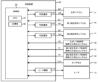
- FIG. 4 is a block diagram showing the electrical connection between a control device 95 and each cell, etc.
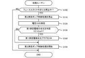
- 11 is a flowchart showing an example of a processing routine.
- 11 is a graph showing a change in voltage V2 depending on whether or not the first measurement electrode 51 has deteriorated.
- 13 is a graph showing the relationship between carbon monoxide concentration and hydrogen concentration and voltage V2.
- FIG. 11 is a schematic cross-sectional view of a sensor element 201 according to a modified example.
- FIG. 1 is a schematic cross-sectional view showing an example of the configuration of a gas sensor 100 according to an embodiment of the present invention.
- FIG. 2 is a block diagram showing the electrical connection between a control device 95 and each cell and a heater 72.
- the gas sensor 100 is attached to a pipe such as an exhaust gas pipe of an internal combustion engine.
- the gas sensor 100 measures a specific gas concentration, which is the concentration of a specific gas in a measured gas, which is exhaust gas from an internal combustion engine.
- the gas sensor 100 measures the water concentration and carbon dioxide concentration as the specific gas concentration.
- the gas sensor 100 includes a sensor element 101 having an element body 102 in the shape of a long rectangular parallelepiped, each cell 21, 41, 50, 80 to 83 included in the sensor element 101, a heater section 70 provided inside the sensor element 101, and a control device 95 having variable power sources 24, 46, 52 and a heater power source 76 and controlling the entire gas sensor 100.
- the longitudinal direction of the sensor element 101 (left-right direction in FIG. 1) is defined as the front-rear direction
- the thickness direction of the sensor element 101 up-down direction in FIG. 1
- the width direction of the sensor element 101 (direction perpendicular to the front-rear direction and up-down direction) is defined as the left-right direction.
- the element body 102 is a laminate in which six layers, namely a first substrate layer 1 , a second substrate layer 2, a third substrate layer 3, a first solid electrolyte layer 4, a spacer layer 5, and a second solid electrolyte layer 6, each of which is made of an oxygen ion conductive solid electrolyte layer such as zirconia (ZrO2), are laminated in this order from the bottom as viewed in the drawing.
- the solid electrolyte forming these six layers is dense and airtight.
- the element body 102 is manufactured, for example, by performing a predetermined processing and printing a circuit pattern on ceramic green sheets corresponding to each layer, laminating them, and further firing them to integrate them.
- the gas inlet 10 At the front end side of the sensor element 101 (element body 102), between the lower surface of the second solid electrolyte layer 6 and the upper surface of the first solid electrolyte layer 4, the gas inlet 10, the first diffusion rate-controlling section 11, the buffer space 12, the second diffusion rate-controlling section 13, the first internal cavity 20, the third diffusion rate-controlling section 30, the second internal cavity 40, the fourth diffusion rate-controlling section 60, and the third internal cavity 61 are adjacently formed and communicated in this order.
- the gas inlet 10, buffer space 12, first internal cavity 20, second internal cavity 40, and third internal cavity 61 are spaces inside the sensor element 101, which are defined by a hollowed-out portion of the spacer layer 5, with the upper portion defined by the underside of the second solid electrolyte layer 6, the lower portion defined by the upper surface of the first solid electrolyte layer 4, and the sides defined by the side surfaces of the spacer layer 5.
- the first diffusion rate-controlling section 11, the second diffusion rate-controlling section 13, and the third diffusion rate-controlling section 30 are each provided as two horizontally elongated slits (with the opening extending in the direction perpendicular to the drawing).
- the fourth diffusion rate-controlling section 60 is provided as a single horizontally elongated slit (with the opening extending in the direction perpendicular to the drawing) formed as a gap with the underside of the second solid electrolyte layer 6.
- the area extending from the gas inlet 10 to the third internal space 61 is also referred to as the measured gas flow section.
- the sensor element 101 (element body 102) is provided with a reference gas inlet 49 that allows a reference gas to flow from the outside of the sensor element 101 to the reference electrode 42 when measuring the concentration of a specific gas.
- the reference gas inlet 49 has a reference gas inlet space 43 and a reference gas inlet layer 48.
- the reference gas inlet space 43 is a space provided inward from the rear end surface of the sensor element 101.
- the reference gas inlet space 43 is provided between the upper surface of the third substrate layer 3 and the lower surface of the spacer layer 5, at a position defined by the side surface of the first solid electrolyte layer 4.
- the reference gas inlet space 43 opens at the rear end surface of the sensor element 101, and this opening functions as an inlet portion 49a of the reference gas inlet 49.
- the reference gas is introduced into the reference gas inlet space 43 from this inlet portion 49a.
- the reference gas inlet 49 introduces the reference gas introduced from the inlet portion 49a into the reference electrode 42 while providing a predetermined diffusion resistance to the reference gas introduced from the inlet portion 49a.
- the reference gas is air.
- the reference gas introduction layer 48 is provided between the upper surface of the third substrate layer 3 and the lower surface of the first solid electrolyte layer 4.
- the reference gas introduction layer 48 is a porous body made of ceramics such as alumina. A portion of the upper surface of the reference gas introduction layer 48 is exposed in the reference gas introduction space 43.
- the reference gas introduction layer 48 is formed so as to cover the reference electrode 42.
- the reference gas introduction layer 48 allows the reference gas to flow from the reference gas introduction space 43 to the reference electrode 42.
- the reference electrode 42 is an electrode formed in a manner sandwiched between the upper surface of the third substrate layer 3 and the first solid electrolyte layer 4, and as described above, a reference gas introduction layer 48 connected to the reference gas introduction space 43 is provided around the reference electrode 42. As will be described later, the reference electrode 42 can be used to measure the oxygen concentration (oxygen partial pressure) in the first internal space 20, the second internal space 40, and the third internal space 61.
- the reference electrode 42 is formed as a porous cermet electrode (for example, a cermet electrode of Pt and ZrO2 ).
- the gas inlet 10 is a section that opens to the external space, and the measured gas is taken into the sensor element 101 from the external space through the gas inlet 10.
- the first diffusion rate-controlling section 11 is a section that imparts a predetermined diffusion resistance to the measured gas taken in from the gas inlet 10.
- the buffer space 12 is a space provided to guide the measured gas introduced from the first diffusion rate-controlling section 11 to the second diffusion rate-controlling section 13.
- the second diffusion rate-controlling section 13 is a section that imparts a predetermined diffusion resistance to the measured gas introduced from the buffer space 12 into the first internal space 20.
- the first internal space 20 is provided as a space for adjusting the oxygen partial pressure in the measurement gas introduced through the second diffusion rate-controlling section 13. The oxygen partial pressure is adjusted by the operation of the main pump cell 21.
- the main pump cell 21 is an electrochemical pump cell that is composed of an inner pump electrode 22 having a ceiling electrode portion 22a provided on almost the entire lower surface of the second solid electrolyte layer 6 facing the first internal space 20, an outer pump electrode 23 provided in a region corresponding to the ceiling electrode portion 22a on the upper surface of the second solid electrolyte layer 6 in a manner that exposes it to the outside of the sensor element 101, and the second solid electrolyte layer 6, spacer layer 5, and first solid electrolyte layer 4 that form a current path between these electrodes.
- the inner pump electrode 22 is formed across the upper and lower solid electrolyte layers (second solid electrolyte layer 6 and first solid electrolyte layer 4) that define the first internal cavity 20, and the spacer layer 5 that provides the side walls. Specifically, a ceiling electrode portion 22a is formed on the lower surface of the second solid electrolyte layer 6 that provides the ceiling surface of the first internal cavity 20, and a bottom electrode portion 22b is formed on the upper surface of the first solid electrolyte layer 4 that provides the bottom surface.
- Side electrode portions are formed on the side wall surfaces (inner surfaces) of the spacer layer 5 that constitute both side wall portions of the first internal cavity 20 so as to connect the ceiling electrode portion 22a and the bottom electrode portion 22b, and are arranged in a tunnel-shaped structure at the locations where the side electrode portions are arranged.
- an electrochemical sensor cell i.e., an oxygen partial pressure detection sensor cell 80 for controlling the main pump, is configured by the inner pump electrode 22, the second solid electrolyte layer 6, the spacer layer 5, the first solid electrolyte layer 4, the third substrate layer 3, and the reference electrode 42.
- the oxygen concentration (oxygen partial pressure) in the first internal space 20 can be determined by measuring the electromotive force (voltage V0) in the oxygen partial pressure detection sensor cell 80 for controlling the main pump. Furthermore, the pump current Ip0 is controlled by feedback controlling the voltage Vp0 of the variable power supply 24 so that the voltage V0 becomes the target value. This adjusts the oxygen concentration in the first internal space 20.
- the third diffusion control section 30 is a section that imparts a predetermined diffusion resistance to the measured gas, the oxygen concentration (oxygen partial pressure) of which is controlled by the operation of the main pump cell 21 in the first internal space 20, and guides the measured gas to the second internal space 40.
- the second internal space 40 is provided as a space for adjusting the oxygen partial pressure of the measurement gas introduced through the third diffusion-controlling section 30 using the first measurement pump cell 50, and for carrying out processing related to measuring the water concentration in the measurement gas.
- the first measurement pump cell 50 is an electrochemical pump cell that is composed of a first measurement electrode 51 having a ceiling electrode portion 51a provided on substantially the entire lower surface of the second solid electrolyte layer 6 facing the second internal space 40, an outer pump electrode 23 (not limited to the outer pump electrode 23, but any suitable electrode disposed on the outer surface of the sensor element 101 will suffice), the second solid electrolyte layer 6, the spacer layer 5, and the first solid electrolyte layer 4.
- the first measurement electrode 51 is disposed in the second internal space 40 in a tunnel-shaped structure similar to the inner pump electrode 22 disposed in the first internal space 20. That is, a ceiling electrode portion 51a is formed on the second solid electrolyte layer 6 that provides the ceiling surface of the second internal space 40, and a bottom electrode portion 51b is formed on the first solid electrolyte layer 4 that provides the bottom surface of the second internal space 40. Side electrodes (not shown) that connect the ceiling electrode portion 51a and the bottom electrode portion 51b are formed on both wall surfaces of the spacer layer 5 that provides the side walls of the second internal space 40, forming a tunnel-shaped structure.
- the first measurement pump cell 50 by applying a desired voltage Vp1 between the first measurement electrode 51 and the outer pump electrode 23, it is possible to pump oxygen in the atmosphere in the second internal space 40 out to the external space, or pump oxygen from the external space into the second internal space 40.
- the first measurement electrode 51, the reference electrode 42, the second solid electrolyte layer 6, the spacer layer 5, the first solid electrolyte layer 4, and the third substrate layer 3 constitute an electrochemical sensor cell, i.e., an oxygen partial pressure detection sensor cell 81 for controlling the first measurement pump.
- the fourth diffusion rate control section 60 is a section that imparts a predetermined diffusion resistance to the measurement gas, the oxygen concentration (oxygen partial pressure) of which has been controlled by the operation of the first measuring pump cell 50 in the second internal space 40, and guides the measurement gas to the third internal space 61.
- the third internal space 61 is provided as a space for adjusting the oxygen partial pressure of the measurement gas introduced through the fourth diffusion-controlling section 60 using the second measurement pump cell 41, and for carrying out processing related to measuring the carbon dioxide concentration in the measurement gas.
- the second measurement pump cell 41 is an electrochemical pump cell composed of a second measurement electrode 44 provided on the upper surface of the first solid electrolyte layer 4 facing the third internal space 61, an outer pump electrode 23 (not limited to the outer pump electrode 23, but any suitable electrode disposed on the outer surface of the sensor element 101 will suffice), a second solid electrolyte layer 6, a spacer layer 5, and the first solid electrolyte layer 4.
- the second measurement pump cell 41 by applying a desired voltage Vp2 between the second measurement electrode 44 and the outer pump electrode 23, it is possible to pump oxygen in the atmosphere in the third internal space 61 out to the external space, or pump oxygen from the external space into the second internal space 40.
- the first solid electrolyte layer 4, the third substrate layer 3, the second measurement electrode 44, and the reference electrode 42 constitute an electrochemical sensor cell, i.e., an oxygen partial pressure detection sensor cell 82 for controlling the second measurement pump.
- variable power supply 46 is controlled based on the electromotive force (voltage V2) detected by the oxygen partial pressure detection sensor cell 82 for controlling the second measurement pump, and the voltage Vp2 of the variable power supply 46 is applied to the second measurement pump cell 41.
- the oxygen partial pressure in the atmosphere in the third internal space 61 is adjusted by the pump current Ip2 flowing through the second measurement pump cell 41.
- the second solid electrolyte layer 6, the spacer layer 5, the first solid electrolyte layer 4, the third substrate layer 3, the outer pump electrode 23, and the reference electrode 42 constitute an electrochemical sensor cell 83, and the electromotive force (voltage Vref) obtained by this sensor cell 83 makes it possible to detect the partial pressure of oxygen in the measured gas outside the sensor.
- the inner pump electrode 22, the first measurement electrode 51, and the second measurement electrode 44 each contain a first-class precious metal having catalytic activity.
- the first-class precious metal include at least one of Pt, Rh, Ir, Ru, and Pd.
- the outer pump electrode 23 and the reference electrode 42 also contain a first-class precious metal. It is preferable that the first measurement electrode 51 contains a second-class precious metal that suppresses the catalytic activity of the first-class precious metal against carbon monoxide. Since the first measurement electrode 51 contains the second-class precious metal, the first measurement electrode 51 has a weakened oxidation ability against carbon monoxide. Examples of the second-class precious metal include Au.
- the inner pump electrode 22 and the second measurement electrode 44 do not contain the second-class precious metal. It is also preferable that the outer pump electrode 23 and the reference electrode 42 do not contain the second-class precious metal.
- Each of the electrodes 22, 23, 42, 44, and 51 is preferably a cermet containing a precious metal and a solid electrolyte (e.g., ZrO2 ) having oxygen ion conductivity.
- Each of the electrodes 22, 23, 42, 44, and 51 is preferably a porous body.
- the first measurement electrode 51 is a porous cermet electrode of Pt containing 1% Au and ZrO2 .
- the inner pump electrode 22, the outer pump electrode 23, the reference electrode 42, and the second measurement electrode 44 are all porous cermet electrodes of Pt and ZrO2.
- the sensor element 101 is equipped with a heater section 70 that adjusts the temperature by heating and keeping the sensor element 101 warm in order to increase the oxygen ion conductivity of the solid electrolyte.
- the heater section 70 is equipped with a heater connector electrode 71, a heater 72, a through hole 73, a heater insulating layer 74, and a pressure release hole 75.
- the heater connector electrode 71 is an electrode formed in such a manner that it is in contact with the underside of the first substrate layer 1. By connecting the heater connector electrode 71 to a heater power supply 76 (see FIG. 2), it is possible to supply power from the heater power supply 76 to the heater section 70.
- the heater 72 is an electrical resistor sandwiched between the second substrate layer 2 and the third substrate layer 3.
- the heater 72 is connected to a heater connector electrode 71 via a through hole 73, and generates heat when power is supplied from a heater power source 76 through the heater connector electrode 71, thereby heating and keeping warm the solid electrolyte that forms the sensor element 101.
- the heater 72 is embedded throughout the entire area from the first internal space 20 to the third internal space 61, making it possible to adjust the temperature of the entire sensor element 101 to a temperature at which the solid electrolyte described above is activated.
- the heater insulating layer 74 is an insulating layer formed of an insulator such as alumina on the upper and lower surfaces of the heater 72.
- the heater insulating layer 74 is formed for the purpose of obtaining electrical insulation between the second substrate layer 2 and the heater 72, and between the third substrate layer 3 and the heater 72.
- the pressure relief hole 75 is a portion that penetrates the third substrate layer 3 and the reference gas introduction layer 48 and is provided so as to communicate with the reference gas introduction space 43, and is formed for the purpose of mitigating the increase in internal pressure that accompanies a rise in temperature within the heater insulation layer 74.
- the control device 95 includes the variable power supplies 24, 46, 52, the heater power supply 76, and a control unit 96.
- the control unit 96 is a microprocessor including a CPU 97 and a memory unit 98.
- the memory unit 98 is a non-volatile memory that allows information to be rewritten, and can store, for example, various programs and various data.
- the control unit 96 inputs the voltage V0 of the oxygen partial pressure detection sensor cell 80 for controlling the main pump, the voltage V1 of the oxygen partial pressure detection sensor cell 81 for controlling the first measurement pump, the voltage V2 of the oxygen partial pressure detection sensor cell 82 for controlling the second measurement pump, the voltage Vref of the sensor cell 83, the pump current Ip0 flowing through the main pump cell 21, the pump current Ip1 flowing through the first measurement pump cell 50, and the pump current Ip2 flowing through the second measurement pump cell 41.
- the control unit 96 also outputs control signals to the variable power sources 24, 52, 46 to control the voltages Vp0, Vp1, Vp2 output by the variable power sources 24, 52, 46, thereby controlling the main pump cell 21, the first measurement pump cell 50, and the second measurement pump cell 41.
- the control unit 96 outputs control signals to the heater power source 76 to control the power supplied by the heater power source 76 to the heater 72.
- the memory unit 98 also stores target values V0*, V1*, V2*, etc., which will be described later.
- the CPU 97 of the control unit 96 controls the cells 21, 50, 41 by referring to these target values V0*, V1*, V2*.
- the control unit 96 performs a main pump control process (an example of a first pump cell control process) that controls the main pump cell 21 to pump oxygen from the periphery of the inner pump electrode 22 to the periphery of the outer pump electrode 23. Specifically, the control unit 96 controls the main pump cell 21 by feedback-controlling the voltage Vp0 of the variable power supply 24 so that the voltage V0 becomes the target value V0*.
- the target value V0* is set as a value that makes the oxygen concentration in the first internal space 20 a predetermined low concentration that is low enough to reduce substantially all of the water and carbon dioxide in the measured gas.
- the water in the measured gas is reduced to generate hydrogen and oxygen
- the carbon dioxide in the measured gas is reduced to generate carbon monoxide and oxygen.
- the generated oxygen is pumped from the periphery of the inner pump electrode 22 to the periphery of the outer pump electrode 23 by the pump current Ip0 flowing through the main pump cell 21.
- the control unit 96 performs a first measurement pump control process (an example of a second pump cell control process) that controls the first measurement pump cell 50 to pump oxygen from around the outer pump electrode 23 to around the first measurement electrode 51. Specifically, the control unit 96 controls the first measurement pump cell 50 by feedback controlling the voltage Vp1 of the variable power supply 52 so that the voltage V1 becomes the target value V1*.
- the target value V1* is set as a value that causes the oxygen concentration in the second internal space 40 to become a predetermined concentration that substantially all of the hydrogen in the second internal space 40 is oxidized.
- the pump current Ip1 flowing through the first measuring pump cell 50 is correlated with the amount of oxygen pumped into the second internal space 40 to oxidize the hydrogen in the second internal space 40, and is also correlated with the amount of water in the measured gas in the first internal space 20 from which the hydrogen in the second internal space 40 was generated. Therefore, the pump current Ip1 is correlated with the water concentration in the measured gas, and the water concentration in the measured gas can be measured based on the pump current Ip1.
- the control unit 96 derives the water concentration in the measured gas based on the pump current Ip1, for example, by using the correspondence between the pump current Ip1 and the water concentration stored in the memory unit 98.
- the correspondence between the pump current Ip1 and the water concentration can be obtained in advance by experiment as a relational equation (for example, a linear or quadratic function equation) or a map.
- a relational equation for example, a linear or quadratic function equation
- a map for example, a map
- the process of measuring the water concentration in the measured gas based on the pump current Ip1 is referred to as a water concentration measurement process.
- the control unit 96 performs a second measurement pump control process (an example of a third pump cell control process) that controls the second measurement pump cell 41 to pump oxygen from around the outer pump electrode 23 to around the second measurement electrode 44. Specifically, the control unit 96 controls the second measurement pump cell 41 by feedback controlling the voltage Vp2 of the variable power supply 46 so that the voltage V2 becomes the target value V2*.
- the target value V2* is set as a value that causes the oxygen concentration in the third internal space 61 to become a predetermined concentration that substantially all of the carbon monoxide in the third internal space 61 is oxidized.
- the pump current Ip2 flowing through the second measuring pump cell 41 is correlated with the amount of oxygen pumped into the third internal space 61 to oxidize the carbon monoxide in the third internal space 61, and is also correlated with the amount of carbon dioxide in the measured gas in the first internal space 20 from which the carbon monoxide in the third internal space 61 was generated. Therefore, the pump current Ip2 is correlated with the carbon dioxide concentration in the measured gas, and the carbon dioxide concentration in the measured gas can be measured based on the pump current Ip2.
- the control unit 96 derives the carbon dioxide concentration in the measured gas based on the pump current Ip2, for example, using the correspondence between the pump current Ip2 and the carbon dioxide concentration stored in the memory unit 98.
- the correspondence between the pump current Ip2 and the carbon dioxide concentration can be determined in advance by experiment as a relational equation (for example, a linear or quadratic function equation) or a map.
- a relational equation for example, a linear or quadratic function equation
- the process of measuring the carbon dioxide concentration in the measured gas based on the pump current Ip2 will be referred to as the carbon dioxide concentration measurement process.
- both hydrogen and carbon monoxide generated in the first internal space 20 reach the second internal space 40.
- hydrogen has a faster gas diffusion rate than carbon monoxide, and hydrogen is more likely to combine with oxygen. Therefore, in the second internal space 40, hydrogen can be selectively oxidized between hydrogen and carbon monoxide by the first measurement pump control process. Since almost no hydrogen reaches the third internal space 61 downstream of the second internal space 40, carbon monoxide can be oxidized by the second measurement pump control process.
- the first measurement electrode 51 contains the second precious metal as described above, which weakens its ability to oxidize carbon monoxide. Therefore, in the vicinity of the first measurement electrode 51, i.e., in the second internal space 40, hydrogen can be selectively oxidized between hydrogen and carbon monoxide by the first measurement pump control process.
- the control unit 96 performs a heater control process that outputs a control signal to the heater power supply 76 to control the temperature of the heater 72 to a target temperature (e.g., 800°C).
- a target temperature e.g. 800°C
- the target temperature of the heater 72 is determined as a temperature at which the above-mentioned solid electrolyte is activated plus a margin.
- the temperature of the heater 72 can be expressed by an equation that is a linear function of the resistance value of the heater 72.
- the control unit 96 calculates the resistance value of the heater 72 as a value that can be regarded as the temperature of the heater 72 (a value that can be converted into a temperature), and feedback controls the heater power supply 76 so that the calculated resistance value becomes the target resistance value (resistance value corresponding to the target temperature).
- the control unit 96 can, for example, obtain the voltage of the heater 72 and the current flowing through the heater 72, and calculate the resistance value of the heater 72 based on the obtained voltage and current.
- the control unit 96 may calculate the resistance value of the heater 72 by, for example, a three-terminal method or a four-terminal method.
- the heater power supply 76 adjusts the power supplied to the heater 72 by, for example, changing the value of the voltage applied to the heater 72 based on a control signal from the control unit 96.
- the control device 95 including the variable power sources 24, 46, 52 and heater power source 76 shown in FIG. 2, is actually connected to each electrode inside the sensor element 101 via lead wires (not shown) formed within the sensor element 101 and connector electrodes (not shown) formed on the rear end side of the sensor element 101 (only the heater connector electrode 71 is shown in FIG. 1).
- the CPU 97 of the control unit 96 first performs the heater control process described above to control the temperature of the heater 72 to the target temperature.
- the CPU 97 starts controlling the pump cells 21, 41, 50 described above (main pump control process, first measurement pump control process, and second measurement pump control process) and acquiring the voltages V0, V1, V2, and Vref from the sensor cells 80 to 83 described above.
- the control unit 96 repeatedly performs a water concentration measurement process and a carbon dioxide concentration measurement process, and performs a deterioration determination process for the first measurement electrode 51 described below.
- the period from the start to the end of the heater control process is considered to be one use of the gas sensor 100.
- the control unit 96 starts the heater control process when it receives a command from the engine ECU (not shown) when the internal combustion engine starts operating, and ends the heater control process when it receives a command from the engine ECU when the internal combustion engine stops operating.
- FIG. 3 is a flow chart showing an example of a processing routine including a deterioration determination process for the first measurement electrode 51.
- This routine is stored in, for example, the memory unit 98 of the control unit 96, and is repeatedly executed by the CPU 97.
- the CPU 97 first determines whether the internal combustion engine is in a fuel cut or stopped state (step S100). For example, the CPU 97 obtains information from the engine ECU that can identify whether the internal combustion engine is in a fuel cut or stopped state, and makes the determination in step S100 based on the obtained information. Alternatively, the CPU 97 may detect the oxygen concentration in the measured gas around the sensor element 101 based on the voltage Vref of the sensor cell 83 described above, and make the determination in step S100 based on whether the detected oxygen concentration is within a high concentration region that can be considered to indicate a fuel cut or stopped state. If the CPU 97 determines in step S100 that the internal combustion engine is neither in a fuel cut nor stopped state, it ends this routine.
- step S100 If the CPU 97 determines in step S100 that the internal combustion engine is in a fuel cut or stopped state, it stops the second measurement pump control process (step S110) and measures the voltage V2 in that state (step S120). That is, the CPU 97 measures the voltage V2 while the main pump control process and the first measurement pump control process are being executed and while the second measurement pump control process is stopped. The CPU 97 then performs a deterioration determination process for the first measurement electrode 51 based on the measured voltage V2 (step S130). The CPU 97 determines whether or not the first measurement electrode 51 has deteriorated based on whether or not the absolute value of the measured voltage V2 is included in a predetermined high voltage region.
- the CPU 97 determines that the first measurement electrode 51 has deteriorated if the absolute value of the measured voltage V2 is greater than a predetermined threshold value V2ref1, and determines that the first measurement electrode 51 has not deteriorated if the absolute value of the measured voltage V2 is equal to or less than the threshold value V2ref1. If the absolute value of the voltage V2 is greater than the threshold value V2ref1 in step S130, the CPU 97 turns on the first measurement electrode deterioration flag (step S140), starts (resumes) the second measurement pump control process (step S150), and ends this routine.
- step S130 If the absolute value of the voltage V2 is equal to or less than the threshold value V2ref1 in step S130, the CPU 97 performs step S150 without turning on the first measurement electrode deterioration flag, and ends this routine.
- the CPU 97 determines in step S130 that the first measurement electrode 51 is deteriorated, it is preferable to notify other devices such as the engine ECU and a user such as a driver of an abnormality in the gas sensor 100.
- the CPU 97 may not perform at least one of the water concentration measurement process and the carbon dioxide concentration measurement process.
- the CPU 97 turns off the first measurement electrode deterioration flag based on an operation by the operator when the deterioration of the first measurement electrode 51 is resolved, for example, after replacing the sensor element 101 in which the first measurement electrode 51 is deteriorated.
- FIG. 4 is a graph showing the change in voltage V2 depending on whether the first measurement electrode 51 is deteriorated.
- FIG. 5 is a graph showing the relationship between the carbon monoxide concentration and hydrogen concentration and the voltage V2.
- the inventors performed the following experiment on the gas sensor 100 to obtain the graphs in FIGS. 4 and 5.
- a gas sensor 100 including an unused (initial state) sensor element 101 and a gas sensor 100 including a sensor element 101 after deterioration of the first measurement electrode 51 were prepared.
- a sensor element 101 was used in which the first measurement electrode 51 was deteriorated by executing a heater control process and a first measurement pump control process for 1000 hours while exposing the tip side of the sensor element 101 to exhaust gas from an internal combustion engine.
- the relationship between the water concentration in the measured gas and the voltage V2 was examined for each of the sensor element 101 in the initial state and the sensor element 101 after deterioration, and the graph in FIG. 4 was obtained.
- the gas sensor 100 equipped with the sensor element 101 in the initial state was attached to the pipe so that the tip side of the sensor element 101 protruded into the pipe.
- a model gas was flowed as the measured gas in the pipe, and the control unit 96 was made to execute the heater control process, the main pump control process, the first measurement pump control process, and the second measurement pump control process.
- the model gas used was a gas in which nitrogen was used as the base gas, the carbon dioxide concentration was 10%, and the water concentration was gradually changed. Then, steps S110 and S120 in FIG.
- the relationship between the carbon monoxide concentration and hydrogen concentration and the voltage V2 was examined for the sensor element 101 in the initial state, and the graph in FIG. 5 was obtained.
- the gas sensor 100 was attached to a pipe in the same manner as in the above-mentioned experiment, and the voltage V2 was measured while a model gas was flowing as the measured gas.
- the control unit 96 was made to execute the heater control process, and the main pump control process, the first measurement pump control process, and the second measurement pump control process were not executed.
- the model gas used was a gas containing carbon monoxide with nitrogen as the base gas.
- the voltage V2 was measured while gradually changing the carbon monoxide concentration of the model gas, and multiple pieces of data were obtained that corresponded between the voltage V2 and the carbon monoxide concentration.
- the model gas was a gas containing hydrogen with nitrogen as the base gas, and the voltage V2 was measured while gradually changing the hydrogen concentration of the model gas, and multiple pieces of data were obtained that corresponded between the voltage V2 and the hydrogen concentration.
- the graph in FIG. 5 plots these data.
- the voltage V2 in the initial state of the sensor element 101, the voltage V2 was almost constant (about 870 mV) regardless of the water concentration, and this value was almost equal to the value of the voltage V2 in FIG. 5 when the carbon monoxide concentration was 10%.
- the voltage V2 in the deteriorated sensor element 101, when the water concentration was 5% or less, the voltage V2 was the same as the voltage V2 of the initial state sensor element 101, but when the water concentration was 10% or more, the voltage V2 was higher than that of the initial state sensor element 101.
- the voltage V2 of the deteriorated sensor element 101 at this time was almost equal to the voltage V2 (about 970 mV) in FIG. 5 when the hydrogen concentration was 10% or more.
- step S130 in FIG. 3 it is determined whether the voltage V2 is included in a predetermined high voltage region, thereby determining whether the first measurement electrode 51 is deteriorated.
- the predetermined high voltage region can be determined in advance by experiments, etc., as a region that the absolute value of the voltage V2 does not reach when carbon monoxide is present around the second measurement electrode 44 but is almost absent, and reaches when hydrogen is present around the second measurement electrode 44.
- the above-mentioned threshold value V2ref1 is set to 920 mV as a value that can distinguish between the voltage V2 when the carbon monoxide concentration is the highest, 15%, in FIG. 5, and the voltage V2 when the hydrogen concentration is the lowest, 0.1%, in FIG. 5, and the region exceeding this threshold value is defined as the high voltage region.
- the voltage V2 also changes depending on the structure of the sensor element 101 (for example, the positions of the second measurement electrode 44 and the reference electrode 42 relative to the heater 72, etc.), so the values of the voltage V2 and the threshold value V2ref1 shown in FIGS. 4 and 5 are merely examples.
- the voltage V2 is controlled to be the target value V2*, and therefore the voltage V2 does not become a value corresponding to the hydrogen concentration or carbon monoxide concentration around the second measurement electrode 44, and therefore deterioration of the first measurement electrode 51 cannot be determined based on the voltage V2.
- the voltage V2 is measured in step S120 with the second measurement pump control process stopped in step S110.
- the main pump control process is not performed, hydrogen is not produced from the water in the measured gas, and if the first measurement pump control process is not performed even if the main pump control process is being performed, hydrogen will reach the second measurement electrode 44 even if the first measurement electrode 51 is not deteriorated. Therefore, the voltage V2 is measured in step S120 while the main pump control process and the first measurement pump control process are being executed.
- the voltage V2 is the same as the voltage V2 of the initial sensor element 101. This is thought to be because even with a deteriorated first measurement electrode 51, if only a small amount of hydrogen reaches the second internal space 40, all of the hydrogen can be oxidized, and no hydrogen reaches the second measurement electrode 44. Therefore, if the first measurement electrode 51 deteriorates further, the voltage V2 will exceed the threshold value V2ref1 even if the water concentration is 5% or less, and it is thought that deterioration can be detected based on the voltage V2.
- deterioration of the first measurement electrode 51 include a decrease in catalytic active sites due to the sintering of the first type precious metal contained in the electrode, which reduces the oxidation ability of the electrode.
- the first measurement electrode 51 contains a second type precious metal, the evaporation of this second type precious metal reduces the three-phase interface between the precious metal, solid electrolyte, and measured gas in the first measurement electrode 51, increasing the resistance of the first measurement electrode 51 and making it difficult for the pump current Ip1 to flow (i.e., the hydrogen oxidation ability of the first measurement electrode 51 decreases).
- the sensor element 101 of this embodiment corresponds to the sensor element of the present invention
- the control device 95 corresponds to the control device.
- the element body 102 corresponds to the element body
- the first internal space 20 corresponds to the first chamber
- the inner pump electrode 22 corresponds to the first inner electrode
- the main pump cell 21 corresponds to the first pump cell
- the second internal space 40 corresponds to the second chamber
- the first measurement electrode 51 corresponds to the second inner electrode
- the first measurement pump cell 50 corresponds to the second pump cell
- the third internal space 61 corresponds to the third chamber
- the second measurement electrode 44 corresponds to the third inner electrode
- the second measurement pump cell 41 corresponds to the third pump cell
- the outer pump electrode 23 corresponds to the first outer electrode
- the reference electrode 42 corresponds to the reference electrode.
- the main pump control process corresponds to the first pump cell control process
- the first measurement pump control process corresponds to the second pump cell control process
- the second measurement pump control process corresponds to the third pump cell control process.
- the pump current Ip1 corresponds to the second pump current
- the pump current Ip2 corresponds to the third pump current
- the voltage V2 corresponds to the third voltage
- the corrected pump current Ip2ad corresponds to the corrected third pump current.
- the deterioration determination process for the first measurement electrode 51 corresponds to the second inner electrode deterioration determination process.
- the control device 95 performs a deterioration determination process for the first measurement electrode 51 based on whether or not the absolute value of the voltage V2 during execution of the main pump control process and the first measurement pump control process and while the second measurement pump control process is stopped is within a predetermined high voltage region.
- the absolute value of the voltage V2 increases as hydrogen reaches the second measurement electrode 44, and therefore deterioration of the first measurement electrode 51 can be determined based on whether or not the absolute value of the voltage V2 is within a predetermined high voltage region.
- the gas to be measured is exhaust gas from an internal combustion engine, and the control device 95 performs a deterioration determination process for the first measurement electrode 51 while the internal combustion engine is being cut off or stopped.
- the exhaust gas (gas in the exhaust gas pipe) while the internal combustion engine is being cut off or stopped has a lower carbon dioxide concentration than the exhaust gas while the internal combustion engine is operating other than when the fuel is cut off, so the influence of carbon monoxide reaching the third internal space 61 becomes smaller in terms of the magnitude of the absolute value of voltage V2, and the influence of hydrogen becomes dominant. Therefore, the timing for performing the deterioration determination process for the first measurement electrode 51 is suitable when the internal combustion engine is being cut off or stopped.
- the first measurement electrode 51 contains the second type precious metal
- one aspect of deterioration of the first measurement electrode 51 is the evaporation of the second type precious metal from the first measurement electrode 51 as the gas sensor 100 is used, which reduces the measurement accuracy of the water concentration and the carbon dioxide concentration. Therefore, when the first measurement electrode 51 contains the second type precious metal, it is highly meaningful to determine the deterioration of the first measurement electrode 51.
- the CPU 97 may perform step S120 after a predetermined waiting time Tw1 has elapsed since executing step S110.
- the waiting time Tw1 may be determined in advance according to the time from when the second measurement pump control process is stopped (the pump current Ip2 is stopped) until the voltage V2 reaches a value corresponding to the hydrogen concentration in the third internal space 61.
- the waiting time Tw1 may be, for example, several milliseconds to a dozen milliseconds.
- the CPU 97 performs the deterioration determination process for the first measurement electrode 51 when the internal combustion engine is in a fuel cut or stopped state, but this is not limited to this.
- the voltage V2 caused by carbon monoxide around the second measurement electrode 44 and the voltage V2 caused by hydrogen have different values. Therefore, even if carbon monoxide is present around the second measurement electrode 44, it is possible to determine whether or not hydrogen is present around the second measurement electrode 44 based on, for example, the measured value of the voltage V2 and the threshold value V2ref1. Therefore, the CPU 97 can perform the deterioration determination process for the first measurement electrode 51 not only during a fuel cut (a timing when the carbon dioxide concentration in the measured gas is low).
- the CPU 97 may determine whether or not the deterioration determination process for the first measurement electrode 51 has not been performed or a predetermined time T1 has elapsed since the previous execution of the process when the gas sensor 100 is currently used, and perform the process from step S110 onwards if the process has not been performed or if the predetermined time T1 has elapsed since the previous execution of the process.
- the predetermined time T1 may be set to, for example, the time from the initial state until the first measurement electrode 51 is likely to deteriorate, or a shorter time, and may be, for example, a few seconds to a few minutes, or about 1,000 hours to a few thousand hours.
- the CPU 97 measures the water concentration and carbon dioxide concentration in the measured gas by executing a water concentration measurement process and a carbon dioxide concentration measurement process.
- the control device 95 may measure only one of the water concentration and carbon dioxide concentration in the measured gas by executing only one of the water concentration measurement process and the carbon dioxide concentration measurement process.
- the outer pump electrode 23 serves as a first outer electrode paired with the inner pump electrode 22 in the main pump cell 21, a second outer electrode paired with the first measurement electrode 51 in the first measurement pump cell 50, and a third outer electrode paired with the second measurement electrode 44 in the second measurement pump cell 41. That is, the first to third outer electrodes are configured as a common outer pump electrode 23. However, this is not limited to this. For example, two of the first to third outer electrodes may be common outer pump electrodes 23, and the remaining one may be an electrode independent of the outer pump electrode 23 and provided on the outer surface of the element body 102 so as to come into contact with the measured gas. Also, the first to third outer electrodes may be provided as independent electrodes so as to come into contact with the measured gas on the outer surface of the element body 102.
- the sensor element 101 of the gas sensor 100 includes the first internal space 20, the second internal space 40, and the third internal space 61, but is not limited thereto.
- the third internal space 61 may not be included.
- the gas inlet 10, the first diffusion rate-controlling portion 11, the buffer space 12, the second diffusion rate-controlling portion 13, the first internal space 20, the third diffusion rate-controlling portion 30, and the second internal space 40 are adjacently formed in this order between the lower surface of the second solid electrolyte layer 6 and the upper surface of the first solid electrolyte layer 4 in a manner that they communicate with each other.
- the second measurement electrode 44 is disposed on the upper surface of the first solid electrolyte layer 4 in the second internal space 40.
- the second measurement electrode 44 is covered with a fourth diffusion rate-controlling portion 45.
- the fourth diffusion rate-controlling portion 45 is a film made of a ceramic porous body such as alumina (Al 2 O 3 ).
- the fourth diffusion rate-controlling portion 45 like the fourth diffusion rate-controlling portion 60 of the above-mentioned embodiment, plays a role of imparting a predetermined diffusion resistance to the measurement gas in the second internal space 40 and guiding it to the second measurement electrode 44.
- the fourth diffusion rate-controlling portion 45 also functions as a protective film for the second measurement electrode 44.
- the ceiling electrode portion 51a of the first measurement electrode 51 is formed up to just above the second measurement electrode 44. Even with the sensor element 201 having such a configuration, like the above-mentioned embodiment, the carbon dioxide concentration can be measured based on the pump current Ip2 flowing through the second measurement pump cell 41.
- the periphery of the second measurement electrode 44 functions as the third chamber. That is, the periphery of the second measurement electrode 44 plays the same role as the third internal space 61.
- the element body 102 of the sensor element 101 is a laminate having multiple solid electrolyte layers (layers 1 to 6), but is not limited to this.
- the element body of the sensor element 101 only needs to have at least one oxygen ion conductive solid electrolyte layer and have a measured gas flow section provided therein.
- layers 1 to 5 other than the second solid electrolyte layer 6 may be structural layers made of a material other than a solid electrolyte (for example, a layer made of alumina).
- each electrode of the sensor element 101 may be disposed on the second solid electrolyte layer 6.
- the second measurement electrode 44 in FIG. 1 may be disposed on the underside of the second solid electrolyte layer 6.
- the reference gas introduction space 43 may be provided in the spacer layer 5 instead of the first solid electrolyte layer 4
- the reference gas introduction layer 48 may be provided between the second solid electrolyte layer 6 and the spacer layer 5 instead of between the first solid electrolyte layer 4 and the third substrate layer 3
- the reference electrode 42 may be provided behind the third internal space 61 and on the underside of the second solid electrolyte layer 6.
- the present invention can be used in gas sensors that measure the water concentration and/or carbon dioxide concentration in a measured gas, such as automobile exhaust gas.
- Second substrate layer 1. First substrate layer, 2. Second substrate layer, 3. Third substrate layer, 4. First solid electrolyte layer, 5. Spacer layer, 6. Second solid electrolyte layer, 10. Gas inlet, 11. First diffusion rate limiting portion, 12. Buffer space, 13. Second diffusion rate limiting portion, 20. First internal space, 21. Main pump cell, 22. Inner pump electrode, 22a. Ceiling electrode portion, 22b. Bottom electrode portion, 23. Outer pump electrode, 24. Variable power source, 30. Third diffusion rate limiting portion, 40. Second internal space, 41. Second measurement pump cell, 42. Reference electrode, 43. Reference gas introduction space, 44. Second measurement electrode, 45. Fourth diffusion rate limiting portion, 46. Variable power source, 48. Reference gas introduction layer, 49. Reference gas introduction portion, 49a. Inlet portion, 50.
- First measurement pump cell 51 first measurement electrode, 51a ceiling electrode portion, 51b bottom electrode portion, 52 variable power supply, 60 fourth diffusion rate control portion, 61 third internal space, 70 heater portion, 71 heater connector electrode, 72 heater, 73 through hole, 74 heater insulating layer, 75 pressure release hole, 76 heater power supply, 80 oxygen partial pressure detection sensor cell for controlling main pump, 81 oxygen partial pressure detection sensor cell for controlling first measurement pump, 82 oxygen partial pressure detection sensor cell for controlling second measurement pump, 83 sensor cell, 95 control device, 96 control portion, 97 CPU, 98 memory portion, 100 gas sensor, 101, 201 sensor element, 102 element body.
Landscapes
- Chemical & Material Sciences (AREA)
- Life Sciences & Earth Sciences (AREA)
- Health & Medical Sciences (AREA)
- Pathology (AREA)
- Chemical Kinetics & Catalysis (AREA)
- Physics & Mathematics (AREA)
- Analytical Chemistry (AREA)
- Biochemistry (AREA)
- General Health & Medical Sciences (AREA)
- General Physics & Mathematics (AREA)
- Immunology (AREA)
- Engineering & Computer Science (AREA)
- Electrochemistry (AREA)
- Molecular Biology (AREA)
- Combustion & Propulsion (AREA)
- Food Science & Technology (AREA)
- Medicinal Chemistry (AREA)
- Mechanical Engineering (AREA)
- General Engineering & Computer Science (AREA)
- Measuring Oxygen Concentration In Cells (AREA)
Priority Applications (4)
| Application Number | Priority Date | Filing Date | Title |
|---|---|---|---|
| DE112024001761.4T DE112024001761T5 (de) | 2023-07-03 | 2024-05-29 | Gassensor |
| CN202480030796.7A CN121420194A (zh) | 2023-07-03 | 2024-05-29 | 气体传感器 |
| JP2025531421A JPWO2025009293A1 (https=) | 2023-07-03 | 2024-05-29 | |
| US19/424,364 US20260110659A1 (en) | 2023-07-03 | 2025-12-18 | Gas sensor |
Applications Claiming Priority (2)
| Application Number | Priority Date | Filing Date | Title |
|---|---|---|---|
| JP2023-109463 | 2023-07-03 | ||
| JP2023109463 | 2023-07-03 |
Related Child Applications (1)
| Application Number | Title | Priority Date | Filing Date |
|---|---|---|---|
| US19/424,364 Continuation US20260110659A1 (en) | 2023-07-03 | 2025-12-18 | Gas sensor |
Publications (1)
| Publication Number | Publication Date |
|---|---|
| WO2025009293A1 true WO2025009293A1 (ja) | 2025-01-09 |
Family
ID=94172015
Family Applications (1)
| Application Number | Title | Priority Date | Filing Date |
|---|---|---|---|
| PCT/JP2024/019677 Ceased WO2025009293A1 (ja) | 2023-07-03 | 2024-05-29 | ガスセンサ |
Country Status (5)
| Country | Link |
|---|---|
| US (1) | US20260110659A1 (https=) |
| JP (1) | JPWO2025009293A1 (https=) |
| CN (1) | CN121420194A (https=) |
| DE (1) | DE112024001761T5 (https=) |
| WO (1) | WO2025009293A1 (https=) |
Citations (6)
| Publication number | Priority date | Publication date | Assignee | Title |
|---|---|---|---|---|
| JPS61195349A (ja) * | 1985-02-25 | 1986-08-29 | Ngk Spark Plug Co Ltd | 内燃機関の空燃比検出装置 |
| JP2015031604A (ja) * | 2013-08-02 | 2015-02-16 | 日本碍子株式会社 | ガスセンサ |
| JP2016142575A (ja) * | 2015-01-30 | 2016-08-08 | 日本碍子株式会社 | ガスセンサ |
| JP2017187403A (ja) * | 2016-04-06 | 2017-10-12 | 日本特殊陶業株式会社 | ガスセンサ素子の劣化判定装置 |
| JP2021135176A (ja) * | 2020-02-27 | 2021-09-13 | 株式会社デンソー | 制御装置 |
| JP2023090025A (ja) * | 2021-12-17 | 2023-06-29 | 日本碍子株式会社 | ガスセンサ |
Family Cites Families (2)
| Publication number | Priority date | Publication date | Assignee | Title |
|---|---|---|---|---|
| JP6469462B2 (ja) | 2015-01-27 | 2019-02-13 | 日本碍子株式会社 | ガスセンサ |
| JP7759616B2 (ja) | 2022-01-27 | 2025-10-24 | パナソニックIpマネジメント株式会社 | 管理装置、収納システム、物品受渡システム及び管理方法 |
-
2024
- 2024-05-29 JP JP2025531421A patent/JPWO2025009293A1/ja active Pending
- 2024-05-29 CN CN202480030796.7A patent/CN121420194A/zh active Pending
- 2024-05-29 WO PCT/JP2024/019677 patent/WO2025009293A1/ja not_active Ceased
- 2024-05-29 DE DE112024001761.4T patent/DE112024001761T5/de active Pending
-
2025
- 2025-12-18 US US19/424,364 patent/US20260110659A1/en active Pending
Patent Citations (6)
| Publication number | Priority date | Publication date | Assignee | Title |
|---|---|---|---|---|
| JPS61195349A (ja) * | 1985-02-25 | 1986-08-29 | Ngk Spark Plug Co Ltd | 内燃機関の空燃比検出装置 |
| JP2015031604A (ja) * | 2013-08-02 | 2015-02-16 | 日本碍子株式会社 | ガスセンサ |
| JP2016142575A (ja) * | 2015-01-30 | 2016-08-08 | 日本碍子株式会社 | ガスセンサ |
| JP2017187403A (ja) * | 2016-04-06 | 2017-10-12 | 日本特殊陶業株式会社 | ガスセンサ素子の劣化判定装置 |
| JP2021135176A (ja) * | 2020-02-27 | 2021-09-13 | 株式会社デンソー | 制御装置 |
| JP2023090025A (ja) * | 2021-12-17 | 2023-06-29 | 日本碍子株式会社 | ガスセンサ |
Also Published As
| Publication number | Publication date |
|---|---|
| US20260110659A1 (en) | 2026-04-23 |
| DE112024001761T5 (de) | 2026-03-05 |
| CN121420194A (zh) | 2026-01-27 |
| JPWO2025009293A1 (https=) | 2025-01-09 |
Similar Documents
| Publication | Publication Date | Title |
|---|---|---|
| JP7590277B2 (ja) | ガスセンサ | |
| JP7653905B2 (ja) | ガスセンサ | |
| US20210302400A1 (en) | Gas sensor and method for controlling operation of gas sensor | |
| US12372494B2 (en) | Gas sensor | |
| JP7286519B2 (ja) | ガスセンサ及びクラック検出方法 | |
| US20240192161A1 (en) | Gas sensor and control method of gas sensor | |
| WO2025009293A1 (ja) | ガスセンサ | |
| WO2025009261A1 (ja) | ガスセンサ | |
| US20260110661A1 (en) | Gas sensor | |
| JP7730753B2 (ja) | ガスセンサ及びガスセンサの制御方法 | |
| JP7695873B2 (ja) | ガスセンサ及びガスセンサの制御方法 | |
| US20240192160A1 (en) | Gas sensor | |
| US12546742B2 (en) | Gas sensor | |
| US20250189481A1 (en) | Gas sensor and method for controlling gas sensor | |
| JP2025111011A (ja) | ガスセンサ | |
| WO2024084889A1 (ja) | ガスセンサ | |
| CN102362174A (zh) | 用于运行传感器元件的方法和传感器元件 | |
| JP2024119106A (ja) | ガスセンサ | |
| WO2024202763A1 (ja) | ガスセンサ | |
| WO2024202731A1 (ja) | ガスセンサ | |
| JP2022153758A (ja) | センサ素子及びガスセンサ | |
| CN117043593A (zh) | 传感器元件以及气体传感器 | |
| JP2016217863A (ja) | ガス濃度検出装置 | |
| JP2022153759A (ja) | センサ素子及びガスセンサ |
Legal Events
| Date | Code | Title | Description |
|---|---|---|---|
| 121 | Ep: the epo has been informed by wipo that ep was designated in this application |
Ref document number: 24835814 Country of ref document: EP Kind code of ref document: A1 |
|
| ENP | Entry into the national phase |
Ref document number: 2025531421 Country of ref document: JP Kind code of ref document: A |
|
| WWE | Wipo information: entry into national phase |
Ref document number: 112024001761 Country of ref document: DE |
|
| WWP | Wipo information: published in national office |
Ref document number: 112024001761 Country of ref document: DE |