WO2025009261A1 - ガスセンサ - Google Patents
ガスセンサ Download PDFInfo
- Publication number
- WO2025009261A1 WO2025009261A1 PCT/JP2024/017338 JP2024017338W WO2025009261A1 WO 2025009261 A1 WO2025009261 A1 WO 2025009261A1 JP 2024017338 W JP2024017338 W JP 2024017338W WO 2025009261 A1 WO2025009261 A1 WO 2025009261A1
- Authority
- WO
- WIPO (PCT)
- Prior art keywords
- pump
- measurement
- electrode
- gas
- pump cell
- Prior art date
- Legal status (The legal status is an assumption and is not a legal conclusion. Google has not performed a legal analysis and makes no representation as to the accuracy of the status listed.)
- Ceased
Links
Images

Classifications
-
- G—PHYSICS
- G01—MEASURING; TESTING
- G01N—INVESTIGATING OR ANALYSING MATERIALS BY DETERMINING THEIR CHEMICAL OR PHYSICAL PROPERTIES
- G01N27/00—Investigating or analysing materials by the use of electric, electrochemical, or magnetic means
- G01N27/26—Investigating or analysing materials by the use of electric, electrochemical, or magnetic means by investigating electrochemical variables; by using electrolysis or electrophoresis
- G01N27/403—Cells and electrode assemblies
- G01N27/406—Cells and probes with solid electrolytes
- G01N27/407—Cells and probes with solid electrolytes for investigating or analysing gases
- G01N27/41—Oxygen pumping cells
-
- G—PHYSICS
- G01—MEASURING; TESTING
- G01N—INVESTIGATING OR ANALYSING MATERIALS BY DETERMINING THEIR CHEMICAL OR PHYSICAL PROPERTIES
- G01N27/00—Investigating or analysing materials by the use of electric, electrochemical, or magnetic means
- G01N27/26—Investigating or analysing materials by the use of electric, electrochemical, or magnetic means by investigating electrochemical variables; by using electrolysis or electrophoresis
- G01N27/403—Cells and electrode assemblies
- G01N27/406—Cells and probes with solid electrolytes
- G01N27/407—Cells and probes with solid electrolytes for investigating or analysing gases
- G01N27/4077—Means for protecting the electrolyte or the electrodes
-
- G—PHYSICS
- G01—MEASURING; TESTING
- G01N—INVESTIGATING OR ANALYSING MATERIALS BY DETERMINING THEIR CHEMICAL OR PHYSICAL PROPERTIES
- G01N27/00—Investigating or analysing materials by the use of electric, electrochemical, or magnetic means
- G01N27/26—Investigating or analysing materials by the use of electric, electrochemical, or magnetic means by investigating electrochemical variables; by using electrolysis or electrophoresis
- G01N27/416—Systems
- G01N27/417—Systems using cells, i.e. more than one cell and probes with solid electrolytes
- G01N27/419—Measuring voltages or currents with a combination of oxygen pumping cells and oxygen concentration cells
-
- G—PHYSICS
- G01—MEASURING; TESTING
- G01N—INVESTIGATING OR ANALYSING MATERIALS BY DETERMINING THEIR CHEMICAL OR PHYSICAL PROPERTIES
- G01N33/00—Investigating or analysing materials by specific methods not covered by groups G01N1/00 - G01N31/00
- G01N33/0004—Gaseous mixtures, e.g. polluted air
- G01N33/0009—General constructional details of gas analysers, e.g. portable test equipment
- G01N33/0027—General constructional details of gas analysers, e.g. portable test equipment concerning the detector
Definitions
- the present invention relates to a gas sensor.
- oxygen is supplied to the vicinity of the surface of the second measurement inner pump electrode by the second measurement pump cell so that carbon monoxide generated by decomposition of the carbon dioxide component is selectively burned near the surface of the second measurement inner pump electrode, and the concentration of the carbon dioxide component present in the measured gas is measured based on the magnitude of the current flowing at this time.
- gas when the gas sensor is in use or not in use, gas may be adsorbed onto at least one of the main inner pump electrode, the first measurement inner pump electrode, and the second measurement inner pump electrode, resulting in a decrease in the reduction or oxidation ability, and thus a decrease in the measurement accuracy of the water concentration and/or the carbon dioxide component concentration.
- the gas sensor of the present invention employs the following means to achieve the above-mentioned main objective.
- the gas sensor of the present invention comprises: A gas sensor for measuring a water concentration and/or a carbon dioxide concentration in a measurement gas, comprising a sensor element and a control device,
- the sensor element includes: an element body having an oxygen ion conductive solid electrolyte layer and a measurement gas flow section for introducing and flowing a measurement gas therein; a first pump cell including a first inner electrode disposed in a first chamber of the measurement target gas flow portion and a first outer electrode disposed on an outer surface of the element body; a second pump cell including a second inner electrode disposed in a second chamber located downstream of the first chamber in the measurement gas flow portion, and a second outer electrode disposed on an outer surface of the element body; a third pump cell including a third inner electrode disposed in a third chamber located downstream of the second chamber in the measurement gas flow portion, and a third outer electrode disposed on an outer surface of the element body,
- the control device includes: a first pump cell control process for controlling the first pump cell to pump oxygen from the periphery
- a first refresh process for controlling the first pump cell to pump oxygen from around the first outer electrode to around the first inner electrode
- a second refresh process for controlling the second pump cell to pump more oxygen from around the second outer electrode to around the second inner electrode compared to the second pump cell control process
- a third refresh process for controlling the third pump cell to pump more oxygen from around the third outer electrode to around the third inner electrode compared to the third pump cell control process.
- the gas adsorbed to the second inner electrode can be oxidized and desorbed from the second inner electrode, and the oxidation ability of the second inner electrode can be restored.
- the third refresh process the gas adsorbed to the third inner electrode can be oxidized and desorbed from the third inner electrode, and the oxidation ability of the third inner electrode can be restored. As a result, the measurement accuracy of the water concentration and/or carbon dioxide concentration in the measured gas can be suppressed from decreasing.
- the gas adsorbed to at least one of the first inner electrode, the second inner electrode, and the third inner electrode can be an exhaust gas component contained in the exhaust gas of the internal combustion engine, or a derived component derived from the exhaust gas component.
- the derived component can be, for example, a reduced component reduced from the exhaust gas component, or an oxidized component oxidized from the reduced component.
- the predetermined conditions may include conditions under which the solid electrolyte layer is activated.
- At least two of the first, second, and third outer electrodes may be common electrodes.
- FIG. 1 is a schematic cross-sectional view showing an example of the configuration of a gas sensor 100 according to an embodiment of the present invention.
- FIG. 2 is a block diagram showing the electrical connection between a control device 95 and each cell and a heater 72.
- the gas sensor 100 is attached to a pipe such as an exhaust gas pipe of an internal combustion engine.
- the gas sensor 100 measures a specific gas concentration, which is the concentration of a specific gas in a measured gas, which is exhaust gas from an internal combustion engine.
- the gas sensor 100 measures the water concentration and carbon dioxide concentration as the specific gas concentration.
- the gas sensor 100 includes a sensor element 101 having an element body 102 in the shape of a long rectangular parallelepiped, each cell 21, 41, 50, 80 to 83 included in the sensor element 101, a heater section 70 provided inside the sensor element 101, and a control device 95 having variable power sources 24, 46, 52 and a heater power source 76 and controlling the entire gas sensor 100.
- the longitudinal direction of the sensor element 101 (left-right direction in FIG. 1) is defined as the front-rear direction
- the thickness direction of the sensor element 101 up-down direction in FIG. 1
- the width direction of the sensor element 101 (direction perpendicular to the front-rear direction and up-down direction) is defined as the left-right direction.
- the element body 102 is a laminate in which six layers, namely a first substrate layer 1 , a second substrate layer 2, a third substrate layer 3, a first solid electrolyte layer 4, a spacer layer 5, and a second solid electrolyte layer 6, each of which is made of an oxygen ion conductive solid electrolyte layer such as zirconia (ZrO2), are laminated in this order from the bottom as viewed in the drawing.
- the solid electrolyte forming these six layers is dense and airtight.
- the element body 102 is manufactured, for example, by performing a predetermined processing and printing a circuit pattern on ceramic green sheets corresponding to each layer, laminating them, and further firing them to integrate them.
- the gas inlet 10 At the front end side of the sensor element 101 (element body 102), between the lower surface of the second solid electrolyte layer 6 and the upper surface of the first solid electrolyte layer 4, the gas inlet 10, the first diffusion rate-controlling section 11, the buffer space 12, the second diffusion rate-controlling section 13, the first internal cavity 20, the third diffusion rate-controlling section 30, the second internal cavity 40, the fourth diffusion rate-controlling section 60, and the third internal cavity 61 are adjacently formed and communicated in this order.
- the gas inlet 10, buffer space 12, first internal cavity 20, second internal cavity 40, and third internal cavity 61 are spaces inside the sensor element 101, which are defined by a hollowed-out portion of the spacer layer 5, with the upper portion defined by the underside of the second solid electrolyte layer 6, the lower portion defined by the upper surface of the first solid electrolyte layer 4, and the sides defined by the side surfaces of the spacer layer 5.
- the first diffusion rate-controlling section 11, the second diffusion rate-controlling section 13, and the third diffusion rate-controlling section 30 are each provided as two horizontally elongated slits (with the opening extending in the direction perpendicular to the drawing).
- the fourth diffusion rate-controlling section 60 is provided as a single horizontally elongated slit (with the opening extending in the direction perpendicular to the drawing) formed as a gap with the underside of the second solid electrolyte layer 6.
- the area extending from the gas inlet 10 to the third internal space 61 is also referred to as the measured gas flow section.
- the sensor element 101 (element body 102) is provided with a reference gas inlet 49 that allows a reference gas to flow from the outside of the sensor element 101 to the reference electrode 42 when measuring the concentration of a specific gas.
- the reference gas inlet 49 has a reference gas inlet space 43 and a reference gas inlet layer 48.
- the reference gas inlet space 43 is a space provided inward from the rear end surface of the sensor element 101.
- the reference gas inlet space 43 is provided between the upper surface of the third substrate layer 3 and the lower surface of the spacer layer 5, at a position defined by the side surface of the first solid electrolyte layer 4.
- the reference gas inlet space 43 opens at the rear end surface of the sensor element 101, and this opening functions as an inlet portion 49a of the reference gas inlet 49.
- the reference gas is introduced into the reference gas inlet space 43 from this inlet portion 49a.
- the reference gas inlet 49 introduces the reference gas introduced from the inlet portion 49a into the reference electrode 42 while providing a predetermined diffusion resistance to the reference gas introduced from the inlet portion 49a.
- the reference gas is air.
- the reference gas introduction layer 48 is provided between the upper surface of the third substrate layer 3 and the lower surface of the first solid electrolyte layer 4.
- the reference gas introduction layer 48 is a porous body made of ceramics such as alumina. A portion of the upper surface of the reference gas introduction layer 48 is exposed in the reference gas introduction space 43.
- the reference gas introduction layer 48 is formed so as to cover the reference electrode 42.
- the reference gas introduction layer 48 allows the reference gas to flow from the reference gas introduction space 43 to the reference electrode 42.
- the reference electrode 42 is an electrode formed in a manner sandwiched between the upper surface of the third substrate layer 3 and the first solid electrolyte layer 4, and as described above, a reference gas introduction layer 48 connected to the reference gas introduction space 43 is provided around the reference electrode 42. As will be described later, the reference electrode 42 can be used to measure the oxygen concentration (oxygen partial pressure) in the first internal space 20, the second internal space 40, and the third internal space 61.
- the reference electrode 42 is formed as a porous cermet electrode (for example, a cermet electrode of Pt and ZrO2 ).
- the gas inlet 10 is a section that opens to the external space, and the measured gas is taken into the sensor element 101 from the external space through the gas inlet 10.
- the first diffusion rate-controlling section 11 is a section that imparts a predetermined diffusion resistance to the measured gas taken in from the gas inlet 10.
- the buffer space 12 is a space provided to guide the measured gas introduced from the first diffusion rate-controlling section 11 to the second diffusion rate-controlling section 13.
- the second diffusion rate-controlling section 13 is a section that imparts a predetermined diffusion resistance to the measured gas introduced from the buffer space 12 into the first internal space 20.
- the first internal space 20 is provided as a space for adjusting the oxygen partial pressure in the measurement gas introduced through the second diffusion rate-controlling section 13. The oxygen partial pressure is adjusted by the operation of the main pump cell 21.
- the main pump cell 21 is an electrochemical pump cell that is composed of an inner pump electrode 22 having a ceiling electrode portion 22a provided on almost the entire lower surface of the second solid electrolyte layer 6 facing the first internal space 20, an outer pump electrode 23 provided in a region corresponding to the ceiling electrode portion 22a on the upper surface of the second solid electrolyte layer 6 in a manner that exposes it to the outside of the sensor element 101, and the second solid electrolyte layer 6, spacer layer 5, and first solid electrolyte layer 4 that form a current path between these electrodes.
- the inner pump electrode 22 is formed across the upper and lower solid electrolyte layers (second solid electrolyte layer 6 and first solid electrolyte layer 4) that define the first internal cavity 20, and the spacer layer 5 that provides the side walls. Specifically, a ceiling electrode portion 22a is formed on the lower surface of the second solid electrolyte layer 6 that provides the ceiling surface of the first internal cavity 20, and a bottom electrode portion 22b is formed on the upper surface of the first solid electrolyte layer 4 that provides the bottom surface.
- Side electrode portions are formed on the side wall surfaces (inner surfaces) of the spacer layer 5 that constitute both side wall portions of the first internal cavity 20 so as to connect the ceiling electrode portion 22a and the bottom electrode portion 22b, and are arranged in a tunnel-shaped structure at the locations where the side electrode portions are arranged.
- the oxygen concentration (oxygen partial pressure) in the first internal space 20 can be determined by measuring the electromotive force (voltage V0) in the oxygen partial pressure detection sensor cell 80 for controlling the main pump. Furthermore, the pump current Ip0 is controlled by feedback controlling the voltage Vp0 of the variable power supply 24 so that the voltage V0 becomes the target value. This adjusts the oxygen concentration in the first internal space 20.
- the third diffusion control section 30 is a section that imparts a predetermined diffusion resistance to the measured gas, the oxygen concentration (oxygen partial pressure) of which is controlled by the operation of the main pump cell 21 in the first internal space 20, and guides the measured gas to the second internal space 40.
- the second internal space 40 is provided as a space for adjusting the oxygen partial pressure of the measurement gas introduced through the third diffusion-controlling section 30 using the first measurement pump cell 50, and for carrying out processing related to measuring the water concentration in the measurement gas.
- the first measurement pump cell 50 is an electrochemical pump cell that is composed of a first measurement electrode 51 having a ceiling electrode portion 51a provided on substantially the entire lower surface of the second solid electrolyte layer 6 facing the second internal space 40, an outer pump electrode 23 (not limited to the outer pump electrode 23, but any suitable electrode disposed on the outer surface of the sensor element 101 will suffice), the second solid electrolyte layer 6, the spacer layer 5, and the first solid electrolyte layer 4.
- the first measurement electrode 51 is disposed in the second internal space 40 in a tunnel-shaped structure similar to the inner pump electrode 22 disposed in the first internal space 20. That is, a ceiling electrode portion 51a is formed on the second solid electrolyte layer 6 that provides the ceiling surface of the second internal space 40, and a bottom electrode portion 51b is formed on the first solid electrolyte layer 4 that provides the bottom surface of the second internal space 40. Side electrodes (not shown) that connect the ceiling electrode portion 51a and the bottom electrode portion 51b are formed on both wall surfaces of the spacer layer 5 that provides the side walls of the second internal space 40, forming a tunnel-shaped structure.
- the first measurement pump cell 50 by applying a desired voltage Vp1 between the first measurement electrode 51 and the outer pump electrode 23, it is possible to pump oxygen in the atmosphere in the second internal space 40 out to the external space, or pump oxygen from the external space into the second internal space 40.
- the first measurement electrode 51, the reference electrode 42, the second solid electrolyte layer 6, the spacer layer 5, the first solid electrolyte layer 4, and the third substrate layer 3 constitute an electrochemical sensor cell, i.e., an oxygen partial pressure detection sensor cell 81 for controlling the first measurement pump.
- the first measurement pump cell 50 performs pumping using a variable power supply 52 whose voltage is controlled based on the electromotive force (voltage V1) detected by the oxygen partial pressure detection sensor cell 81 for controlling the first measurement pump.
- V1 electromotive force
- the fourth diffusion rate control section 60 is a section that imparts a predetermined diffusion resistance to the measurement gas whose oxygen concentration (oxygen partial pressure) has been controlled by the operation of the first measuring pump cell 50 in the second internal space 40, and guides the measurement gas to the third internal space 61.
- the third internal space 61 is provided as a space for adjusting the oxygen partial pressure of the measurement gas introduced through the fourth diffusion-controlling section 60 using the second measurement pump cell 41, and for carrying out processing related to measuring the carbon dioxide concentration in the measurement gas.
- the second measurement pump cell 41 is an electrochemical pump cell composed of a second measurement electrode 44 provided on the upper surface of the first solid electrolyte layer 4 facing the third internal space 61, an outer pump electrode 23 (not limited to the outer pump electrode 23, but any suitable electrode disposed on the outer surface of the sensor element 101 will suffice), a second solid electrolyte layer 6, a spacer layer 5, and the first solid electrolyte layer 4.
- the second measurement pump cell 41 by applying a desired voltage Vp2 between the second measurement electrode 44 and the outer pump electrode 23, it is possible to pump oxygen in the atmosphere in the third internal space 61 out to the external space, or pump oxygen from the external space into the second internal space 40.
- the first solid electrolyte layer 4, the third substrate layer 3, the second measurement electrode 44, and the reference electrode 42 constitute an electrochemical sensor cell, i.e., an oxygen partial pressure detection sensor cell 82 for controlling the second measurement pump.
- variable power supply 46 is controlled based on the electromotive force (voltage V2) detected by the oxygen partial pressure detection sensor cell 82 for controlling the second measurement pump, and the voltage Vp2 of the variable power supply 46 is applied to the second measurement pump cell 41.
- the oxygen partial pressure in the atmosphere in the third internal space 61 is adjusted by the pump current Ip2 flowing through the second measurement pump cell 41.
- the second solid electrolyte layer 6, the spacer layer 5, the first solid electrolyte layer 4, the third substrate layer 3, the outer pump electrode 23, and the reference electrode 42 constitute an electrochemical sensor cell 83, and the electromotive force (voltage Vref) obtained by this sensor cell 83 makes it possible to detect the partial pressure of oxygen in the measured gas outside the sensor.
- the inner pump electrode 22, the first measurement electrode 51, and the second measurement electrode 44 each contain a first-class precious metal having catalytic activity.
- the first-class precious metal include at least one of Pt, Rh, Ir, Ru, and Pd.
- the outer pump electrode 23 and the reference electrode 42 also contain a first-class precious metal. It is preferable that the first measurement electrode 51 contains a second-class precious metal that suppresses the catalytic activity of the first-class precious metal against carbon monoxide. Since the first measurement electrode 51 contains the second-class precious metal, the first measurement electrode 51 has a weakened oxidation ability against carbon monoxide. Examples of the second-class precious metal include Au.
- the inner pump electrode 22 and the second measurement electrode 44 do not contain the second-class precious metal. It is also preferable that the outer pump electrode 23 and the reference electrode 42 do not contain the second-class precious metal.
- Each of the electrodes 22, 23, 42, 44, and 51 is preferably a cermet containing a precious metal and an oxide having oxygen ion conductivity (e.g., ZrO2 ) .
- Each of the electrodes 22, 23, 42, 44, and 51 is preferably a porous body.
- the first measurement electrode 51 is a porous cermet electrode of Pt containing 1% Au and ZrO2.
- the inner pump electrode 22, the outer pump electrode 23, the reference electrode 42, and the second measurement electrode 44 are all porous cermet electrodes of Pt and ZrO2 .
- the sensor element 101 is equipped with a heater section 70 that adjusts the temperature by heating and keeping the sensor element 101 warm in order to increase the oxygen ion conductivity of the solid electrolyte.
- the heater section 70 is equipped with a heater connector electrode 71, a heater 72, a through hole 73, a heater insulating layer 74, and a pressure release hole 75.
- the heater connector electrode 71 is an electrode formed in such a manner that it is in contact with the underside of the first substrate layer 1. By connecting the heater connector electrode 71 to a heater power supply 76 (see FIG. 2), it is possible to supply power from the heater power supply 76 to the heater section 70.
- the heater 72 is an electrical resistor sandwiched between the second substrate layer 2 and the third substrate layer 3.
- the heater 72 is connected to a heater connector electrode 71 via a through hole 73, and generates heat when power is supplied from a heater power source 76 through the heater connector electrode 71, thereby heating and keeping warm the solid electrolyte that forms the sensor element 101.
- the heater 72 is embedded throughout the entire area from the first internal space 20 to the third internal space 61, making it possible to adjust the temperature of the entire sensor element 101 to a temperature at which the solid electrolyte described above is activated.
- the pressure relief hole 75 is a portion that penetrates the third substrate layer 3 and the reference gas introduction layer 48 and is provided so as to communicate with the reference gas introduction space 43, and is formed for the purpose of mitigating the increase in internal pressure that accompanies an increase in temperature within the heater insulation layer 74.
- the control device 95 includes the variable power supplies 24, 46, 52, the heater power supply 76, and a control unit 96.
- the control unit 96 is a microprocessor including a CPU 97 and a memory unit 98.
- the memory unit 98 is a non-volatile memory that allows information to be rewritten, and can store, for example, various programs and various data.
- the control unit 96 inputs the voltage V0 of the oxygen partial pressure detection sensor cell 80 for controlling the main pump, the voltage V1 of the oxygen partial pressure detection sensor cell 81 for controlling the first measurement pump, the voltage V2 of the oxygen partial pressure detection sensor cell 82 for controlling the second measurement pump, the voltage Vref of the sensor cell 83, the pump current Ip0 flowing through the main pump cell 21, the pump current Ip1 flowing through the first measurement pump cell 50, and the pump current Ip2 flowing through the second measurement pump cell 41.
- the control unit 96 also outputs control signals to the variable power sources 24, 52, 46 to control the voltages Vp0, Vp1, Vp2 output by the variable power sources 24, 52, 46, thereby controlling the main pump cell 21, the first measurement pump cell 50, and the second measurement pump cell 41.
- the control unit 96 outputs control signals to the heater power source 76 to control the power supplied by the heater power source 76 to the heater 72.
- the memory unit 98 also stores target values V0*, V1*, V2*, etc., which will be described later.
- the CPU 97 of the control unit 96 controls the cells 21, 50, 41 by referring to these target values V0*, V1*, V2*.
- the control unit 96 performs a main pump control process (an example of a first pump cell control process) that controls the main pump cell 21 to pump oxygen from the periphery of the inner pump electrode 22 to the periphery of the outer pump electrode 23. Specifically, the control unit 96 controls the main pump cell 21 by feedback-controlling the voltage Vp0 of the variable power supply 24 so that the voltage V0 becomes the target value V0*.
- the target value V0* is set as a value that makes the oxygen concentration in the first internal space 20 a predetermined low concentration that is low enough to reduce substantially all of the water and carbon dioxide in the measured gas.
- the water in the measured gas is reduced to generate hydrogen and oxygen
- the carbon dioxide in the measured gas is reduced to generate carbon monoxide and oxygen.
- the generated oxygen is pumped from the periphery of the inner pump electrode 22 to the periphery of the outer pump electrode 23 by the pump current Ip0 flowing through the main pump cell 21.
- the control unit 96 performs a first measurement pump control process (an example of a second pump cell control process) that controls the first measurement pump cell 50 to pump oxygen from around the outer pump electrode 23 to around the first measurement electrode 51. Specifically, the control unit 96 controls the first measurement pump cell 50 by feedback controlling the voltage Vp1 of the variable power supply 52 so that the voltage V1 becomes the target value V1*.
- the target value V1* is set as a value that causes the oxygen concentration in the second internal space 40 to become a predetermined concentration that substantially all of the hydrogen in the second internal space 40 is oxidized.
- the pump current Ip1 flowing through the first measuring pump cell 50 is correlated with the amount of oxygen pumped into the second internal space 40 to oxidize the hydrogen in the second internal space 40, and is also correlated with the amount of water in the measured gas in the first internal space 20 that was the source of the hydrogen in the second internal space 40. Therefore, the pump current Ip1 is correlated with the water concentration in the measured gas, and the water concentration in the measured gas can be measured based on the pump current Ip1.
- the process of measuring the water concentration in the measured gas based on the pump current Ip1 is referred to as the water concentration measurement process.
- the control unit 96 performs a second measurement pump control process (an example of a third pump cell control process) that controls the second measurement pump cell 41 to pump oxygen from around the outer pump electrode 23 to around the second measurement electrode 44. Specifically, the control unit 96 controls the second measurement pump cell 41 by feedback controlling the voltage Vp2 of the variable power supply 46 so that the voltage V2 becomes the target value V2*.
- the target value V2* is set as a value that causes the oxygen concentration in the third internal space 61 to become a predetermined concentration that substantially all of the carbon monoxide in the third internal space 61 is oxidized.
- both hydrogen and carbon monoxide generated in the first internal space 20 reach the second internal space 40.
- hydrogen has a faster gas diffusion rate than carbon monoxide, and hydrogen is more likely to combine with oxygen. Therefore, in the second internal space 40, hydrogen can be selectively oxidized between hydrogen and carbon monoxide by the first measurement pump control process. Since almost no hydrogen reaches the third internal space 61 downstream of the second internal space 40, carbon monoxide can be oxidized by the second measurement pump control process.
- the first measurement electrode 51 contains the second precious metal, which weakens its ability to oxidize carbon monoxide. Therefore, in the vicinity of the first measurement electrode 51, i.e., in the second internal space 40, hydrogen can be more selectively oxidized between hydrogen and carbon monoxide by the first measurement pump control process.
- the control unit 96 performs a heater control process that outputs a control signal to the heater power supply 76 to control the temperature of the heater 72 to a target temperature (e.g., 800°C).
- a target temperature e.g. 800°C
- the target temperature of the heater 72 is determined as a temperature at which the above-mentioned solid electrolyte is activated plus a margin.
- the temperature of the heater 72 can be expressed by an equation that is a linear function of the resistance value of the heater 72.
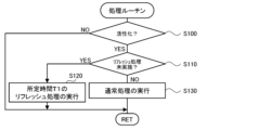
- FIG. 3 is a flow chart showing an example of a processing routine executed by the CPU 97 of the control unit 96.
- This routine is stored in, for example, the memory unit 98 of the control unit 96, and is repeatedly executed by the CPU 97.
- the CPU 97 controls the temperature of the heater 72 to a target temperature (for example, 800°C) through a heater control process.
- a target temperature for example, 800°C
- the period from the start to the end of the heater control process is considered to be one use of the gas sensor 100.
- the predetermined time T1 is, for example, a few seconds to a few minutes.
- the CPU 97 executes the first, second, and third refresh processes.
- the first refresh process is a process for controlling the main pump cell 21 so as to pump oxygen from around the outer pump electrode 23 to around the inner pump electrode 22.
- the second refresh process is a process for controlling the first measurement pump cell 50 so as to pump more oxygen from around the outer pump electrode 23 to around the first measurement electrode 51 compared to the first measurement pump control process.
- the third refresh process is a process for controlling the second measurement pump cell 41 so as to pump more oxygen from around the outer pump electrode 23 to around the second measurement electrode 44 compared to the second measurement pump control process.
- the CPU 97 controls the main pump cell 21 by feedback-controlling the voltage Vp0 of the variable power supply 24 so that the voltage V0 becomes a target value V0r* that is smaller in absolute value than the target value V0*.
- the target value V0r* is set as a value that makes the oxygen concentration in the first internal space 20 higher than when the main pump control process is executed.
- the control unit 96 controls the first measurement pump cell 50 by feedback-controlling the voltage Vp1 of the variable power supply 52 so that the voltage V1 becomes a target value V1r* that is smaller in absolute value than the target value V1*.
- the target value V1r* is set as a value that makes the oxygen concentration in the second internal space 40 higher (closer to the reference gas) than when the first measurement pump control process is executed.
- the control unit 96 controls the second measurement pump cell 41 by feedback-controlling the voltage Vp2 of the variable power supply 46 so that the voltage V2 becomes a target value V2r* whose absolute value is smaller than the target value V2*.
- the target value V2r* is set as a value that makes the oxygen concentration in the third internal space 61 higher (closer to the reference gas) than when the second measurement pump control process is executed.
- gas when the gas sensor 100 is in use or is not in use, gas may be adsorbed to at least one of the inner pump electrode 22, the first measurement electrode 51, and the second measurement electrode 44, resulting in a decrease in the reduction ability or oxidation ability, and thus a decrease in the measurement accuracy of the water concentration and the concentration of the carbon dioxide component.
- the gas adsorbed to the inner pump electrode 22 can be oxidized and desorbed from the inner pump electrode 22, and the reduction ability of the inner pump electrode 22 can be restored.
- the second refresh process the gas adsorbed to the first measurement electrode 51 can be oxidized and desorbed from the first measurement electrode 51, and the oxidation ability of the first measurement electrode 51 can be restored.
- the gas adsorbed to the second measurement electrode 44 can be oxidized and desorbed from the second measurement electrode 44, and the oxidation ability of the second measurement electrode 44 can be restored.
- the gas sensor 100 is attached to an exhaust gas pipe of an internal combustion engine.
- the gas adsorbed to at least one of the inner pump electrode 22, the first measurement electrode 51, and the second measurement electrode 44 may be an exhaust gas component that is a component contained in the exhaust gas of the internal combustion engine, or a derived component derived from the exhaust gas component.
- the derived component may be, for example, a reduced component that is reduced from the exhaust gas component, or an oxidized component that is oxidized from the reduced component.
- the CPU 97 determines in step S110 that the refresh process has been performed for the current use of the gas sensor 100, it executes normal processing (step S130) and ends this routine.
- the CPU 97 executes a main pump control process, a first measurement pump control process, a second measurement pump control process, a water concentration measurement process, and a carbon dioxide concentration measurement process.
- the gas sensor 100 was attached to the pipe so that the tip side portion of the sensor element 101 protruded into the pipe, the solid electrolyte of the sensor element 101 was activated by the heater control processing, and the refresh processing was performed (step S120), and the carbon dioxide concentration was gradually increased, and the pump current Ip2 was detected at each concentration (step S130), after which the heater control processing was terminated and the gas sensor 100 was removed from the pipe.
- nitrogen was used as the base gas as a model gas with gradually changing carbon dioxide concentrations.
- the refresh process by performing the refresh process, it is possible to suppress the decrease in the measurement accuracy of the carbon dioxide concentration in the measured gas compared to the first, second, and fourth experimental processes. Similarly, it is considered that when the refresh process is performed, the decrease in the measurement accuracy of the water concentration in the measured gas can also be suppressed compared to when the refresh process is not performed.
- the sensor element 101 of this embodiment corresponds to the sensor element of the present invention
- the control device 95 corresponds to the control device.
- the element body 102 corresponds to the element body
- the first internal space 20 corresponds to the first chamber
- the inner pump electrode 22 corresponds to the first inner electrode
- the main pump cell 21 corresponds to the first pump cell
- the second internal space 40 corresponds to the second chamber
- the first measurement electrode 51 corresponds to the second inner electrode
- the first measurement pump cell 50 corresponds to the second pump cell
- the third internal space 61 corresponds to the third chamber
- the second measurement electrode 44 corresponds to the third inner electrode
- the second measurement pump cell 41 corresponds to the third pump cell
- the outer pump electrode 23 corresponds to the first outer electrode, the second outer electrode, and the third outer electrode.
- the main pump control process corresponds to the first pump cell control process
- the first measurement pump control process corresponds to the second pump cell control process
- the second measurement pump control process corresponds to the third pump cell control process.
- the control device 95 executes a refresh process, specifically, the first to third refresh processes, when the solid electrolyte of the sensor element 101 is activated. This makes it possible to recover the reducing and oxidizing capabilities of the inner pump electrode 22, the first measurement electrode 51, and the second measurement electrode 44. As a result, it is possible to suppress a decrease in the measurement accuracy of the water concentration and carbon dioxide concentration in the measured gas.
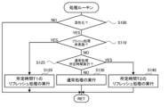
- the CPU 97 executes the processing routine of FIG. 3, but instead, it may execute the processing routine of FIG. 5.
- the processing routine of FIG. 5 is the same as the processing routine of FIG. 3 except for the addition of steps S125 and S140. Therefore, the same step numbers are used for the processing in the processing routine of FIG. 5 that is the same as the processing routine of FIG. 3, and detailed explanations will be omitted.
- step S110 determines whether or not the normal process has been continuously performed for a predetermined time ⁇ T (the predetermined time ⁇ T has elapsed since the previous refresh process) (step S125).
- the normal process has been continuously performed for a predetermined time ⁇ T means that in this routine, the normal process (step S130) has been repeatedly performed without performing the refresh process for the predetermined time ⁇ T.
- the predetermined time ⁇ T is a few seconds to a few minutes.
- the CPU 97 determines in step S125 that normal processing has been performed continuously for a predetermined time ⁇ T, it performs a refresh process for a predetermined time T2 (step S140) and ends this routine.
- the predetermined time T2 is set to a time equal to or less than the predetermined time T1, and may be, for example, several milliseconds to several seconds. This allows the refresh process to be performed periodically (at intervals of the predetermined time ⁇ T). As a result, the frequency of the refresh process can be ensured, and a decrease in the measurement accuracy of the water concentration and carbon dioxide concentration in the measured gas can be suppressed.
- the CPU 97 executes a refresh process for a predetermined time T1 when the solid electrolyte of the sensor element 101 is activated (step S120), and thereafter executes a refresh process for a predetermined time T2 (step S140) each time normal processing is continuously executed for a predetermined time ⁇ T. However, the CPU 97 does not have to execute the refresh process for the predetermined time T1.
- the CPU 97 determines whether the solid electrolyte of the sensor element 101 is activated by determining whether the resistance value of the heater 72 is equal to or less than a predetermined resistance value, but this is not limited to the above.
- the CPU 97 may determine whether the solid electrolyte is activated by determining whether the execution time of the heater control process is equal to or more than a predetermined time.
- the CPU 97 controls the main pump cell 21 as the first refresh process by feedback-controlling the voltage Vp0 of the variable power supply 24 so that the voltage V0 becomes a target value V0r* that is smaller in absolute value than the target value V0*, but this is not limited to the above.
- the CPU 97 may control the main pump cell 21 as the first refresh process by feedback-controlling the voltage Vp0 of the variable power supply 24 so that the pump current Ip0 becomes the target value Ip0r*.
- the target value Ip0r* is a value in the direction in which oxygen is pumped into the first internal space 20, and is set to a value with an opposite sign to that when the main pump control process is being executed.
- the CPU 97 controls the first measurement pump cell 50 as the second refresh process by feedback-controlling the voltage Vp1 of the variable power supply 52 so that the voltage V1 becomes the target value V1r* which is smaller in absolute value than the target value V1*, but this is not limited to the above.
- the CPU 97 may control the first measurement pump cell 50 as the second refresh process by feedback-controlling the voltage Vp1 of the variable power supply 52 so that the pump current Ip1 becomes the target value Ip1r*.
- the target value Ip1r* is set to a value larger in absolute value than the pump current Ip1 that normally flows when the first measurement pump control process is being executed.
- the CPU 97 controls the second measurement pump cell 41 as the third refresh process by feedback-controlling the voltage Vp2 of the variable power supply 46 so that the voltage V2 becomes the target value V2r*, which has an absolute value smaller than the target value V2*; however, this is not limited to this.
- the CPU 97 may control the second measurement pump cell 41 as the third refresh process by feedback-controlling the voltage Vp2 of the variable power supply 46 so that the pump current Ip2 becomes the target value Ip2r*.
- the target value Ip2r* is set to a value with an absolute value larger than the pump current Ip2 that normally flows when the second measurement pump control process is being executed.
- the CPU 97 executes the first, second, and third refresh processes as the refresh process.
- only parts of the first, second, and third refresh processes may be executed as the refresh process.
- the inventors have found through experiments and analysis that when the gas sensor 100 is in use or not in use, gas is likely to be adsorbed onto the inner pump electrode 22, the first measurement electrode 51, and the second measurement electrode 44, particularly the inner pump electrode 22, which may cause a decrease in the reduction ability. For this reason, when only parts of the first, second, and third refresh processes are executed as the refresh process, it is preferable to execute at least the first refresh process.
- the CPU 97 measures the water concentration and carbon dioxide concentration in the measured gas by executing a water concentration measurement process and a carbon dioxide concentration measurement process.
- the control device 95 may measure only one of the water concentration and carbon dioxide concentration in the measured gas by executing only one of the water concentration measurement process and the carbon dioxide concentration measurement process.
- the outer pump electrode 23 serves as a first outer electrode paired with the inner pump electrode 22 in the main pump cell 21, a second outer electrode paired with the first measurement electrode 51 in the first measurement pump cell 50, and a third outer electrode paired with the second measurement electrode 44 in the second measurement pump cell 41. That is, the first to third outer electrodes are configured as a common outer pump electrode 23. However, this is not limited to this. For example, two of the first to third outer electrodes may be common outer pump electrodes 23, and the remaining one may be an electrode independent of the outer pump electrode 23 and provided on the outer surface of the element body 102 so as to come into contact with the measured gas. Also, the first to third outer electrodes may be provided as independent electrodes so as to come into contact with the measured gas on the outer surface of the element body 102.
- the sensor element 101 of the gas sensor 100 includes the first internal space 20, the second internal space 40, and the third internal space 61, but is not limited thereto.
- the third internal space 61 may not be included.
- the gas inlet 10, the first diffusion rate-controlling portion 11, the buffer space 12, the second diffusion rate-controlling portion 13, the first internal space 20, the third diffusion rate-controlling portion 30, and the second internal space 40 are adjacently formed in this order between the lower surface of the second solid electrolyte layer 6 and the upper surface of the first solid electrolyte layer 4 in a manner that they communicate with each other.
- the second measurement electrode 44 is disposed on the upper surface of the first solid electrolyte layer 4 in the second internal space 40.
- the second measurement electrode 44 is covered with a fourth diffusion rate-controlling portion 45.
- the fourth diffusion rate-controlling portion 45 is a film made of a ceramic porous body such as alumina (Al 2 O 3 ).
- the fourth diffusion rate-controlling portion 45 like the fourth diffusion rate-controlling portion 60 of the above-mentioned embodiment, plays a role of imparting a predetermined diffusion resistance to the measurement gas in the second internal space 40 and guiding it to the second measurement electrode 44.
- the fourth diffusion rate-controlling portion 45 also functions as a protective film for the second measurement electrode 44.
- the ceiling electrode portion 51a of the first measurement electrode 51 is formed up to just above the second measurement electrode 44. Even with the sensor element 201 having such a configuration, like the above-mentioned embodiment, the carbon dioxide concentration can be measured based on the pump current Ip2 flowing through the second measurement pump cell 41.
- the periphery of the second measurement electrode 44 functions as the third chamber. That is, the periphery of the second measurement electrode 44 plays the same role as the third internal space 61.
- the element body 102 of the sensor element 101 is a laminate having multiple solid electrolyte layers (layers 1 to 6), but is not limited to this.
- the element body of the sensor element 101 only needs to have at least one oxygen ion conductive solid electrolyte layer and have a measured gas flow section provided therein.
- layers 1 to 5 other than the second solid electrolyte layer 6 may be structural layers made of a material other than a solid electrolyte (for example, a layer made of alumina).
- each electrode of the sensor element 101 may be disposed on the second solid electrolyte layer 6.
- the second measurement electrode 44 in FIG. 1 may be disposed on the underside of the second solid electrolyte layer 6.
- the reference gas introduction space 43 may be provided in the spacer layer 5 instead of the first solid electrolyte layer 4
- the reference gas introduction layer 48 may be provided between the second solid electrolyte layer 6 and the spacer layer 5 instead of between the first solid electrolyte layer 4 and the third substrate layer 3
- the reference electrode 42 may be provided behind the third internal space 61 and on the underside of the second solid electrolyte layer 6.
- the first diffusion rate-controlling section 11, the second diffusion rate-controlling section 13, and the third diffusion rate-controlling section 30 are each provided as two horizontally long slits, but this is not limited to this.
- one or more of the first diffusion rate-controlling section 11, the second diffusion rate-controlling section 13, and the third diffusion rate-controlling section 30 may be provided as a single horizontally long slit.
- the present invention can be used in gas sensors that measure the water concentration and/or carbon dioxide concentration in a measured gas, such as automobile exhaust gas.
- Second substrate layer 1. First substrate layer, 2. Second substrate layer, 3. Third substrate layer, 4. First solid electrolyte layer, 5. Spacer layer, 6. Second solid electrolyte layer, 10. Gas inlet, 11. First diffusion rate limiting portion, 12. Buffer space, 13. Second diffusion rate limiting portion, 20. First internal space, 21. Main pump cell, 22. Inner pump electrode, 22a. Ceiling electrode portion, 22b. Bottom electrode portion, 23. Outer pump electrode, 24. Variable power source, 30. Third diffusion rate limiting portion, 40. Second internal space, 41. Second measurement pump cell, 42. Reference electrode, 43. Reference gas introduction space, 44. Second measurement electrode, 45. Fourth diffusion rate limiting portion, 46. Variable power source, 48. Reference gas introduction layer, 49. Reference gas introduction portion, 49a. Inlet portion, 50.
- First measurement pump cell 51 first measurement electrode, 51a ceiling electrode portion, 51b bottom electrode portion, 52 variable power supply, 60 fourth diffusion rate control portion, 61 third internal space, 70 heater portion, 71 heater connector electrode, 72 heater, 73 through hole, 74 heater insulating layer, 75 pressure release hole, 76 heater power supply, 80 oxygen partial pressure detection sensor cell for controlling main pump, 81 oxygen partial pressure detection sensor cell for controlling first measurement pump, 82 oxygen partial pressure detection sensor cell for controlling second measurement pump, 83 sensor cell, 95 control device, 96 control portion, 97 CPU, 98 memory portion, 100 gas sensor, 101, 201 sensor element, 102 element body.
Landscapes
- Chemical & Material Sciences (AREA)
- Health & Medical Sciences (AREA)
- Life Sciences & Earth Sciences (AREA)
- Analytical Chemistry (AREA)
- General Health & Medical Sciences (AREA)
- Pathology (AREA)
- Immunology (AREA)
- Physics & Mathematics (AREA)
- General Physics & Mathematics (AREA)
- Biochemistry (AREA)
- Molecular Biology (AREA)
- Chemical Kinetics & Catalysis (AREA)
- Electrochemistry (AREA)
- Engineering & Computer Science (AREA)
- Combustion & Propulsion (AREA)
- Medicinal Chemistry (AREA)
- Food Science & Technology (AREA)
- Measuring Oxygen Concentration In Cells (AREA)
Abstract
Description
センサ素子および制御装置を備え、被測定ガス中の水濃度および/または二酸化炭素濃度を測定するガスセンサであって、
前記センサ素子は、
酸素イオン伝導性の固体電解質層を有し、被測定ガスを導入して流通させる被測定ガス流通部が内部に設けられた素子本体と、
前記被測定ガス流通部のうちの第1室に配設された第1内側電極と、前記素子本体の外面に配設された第1外側電極と、を含んで構成された第1ポンプセルと、
前記被測定ガス流通部のうちの前記第1室よりも下流に位置する第2室に配設された第2内側電極と、前記素子本体の外面に配設された第2外側電極と、を含んで構成された第2ポンプセルと、
前記被測定ガス流通部のうちの前記第2室よりも下流に位置する第3室に配設された第3内側電極と、前記素子本体の外面に配設された第3外側電極と、を含んで構成された第3ポンプセルとを有し、
前記制御装置は、
前記第1内側電極の周囲から前記第1外側電極の周囲に酸素を汲み出すように前記第1ポンプセルを制御して前記第1室内の前記被測定ガス中の水と二酸化炭素とを還元する第1ポンプセル制御処理と、
前記第2外側電極の周囲から前記第2内側電極の周囲に酸素を汲み入れるように前記第2ポンプセルを制御して、前記第1室内における水の還元で生じた水素を前記第2室で酸化させる第2ポンプセル制御処理と、
前記第3外側電極の周囲から前記第3内側電極の周囲に酸素を汲み入れるように前記第3ポンプセルを制御して、前記第1室内における二酸化炭素の還元で生じた一酸化炭素を前記第3室で酸化させる第3ポンプセル制御処理と、
前記第2ポンプセル制御処理により前記第2ポンプセルに流れる第2ポンプ電流に基づいて前記被測定ガス中の水濃度を測定する水濃度測定処理、および/または、前記第3ポンプセル制御処理により前記第3ポンプセルに流れる第3ポンプ電流に基づいて前記被測定ガス中の二酸化炭素濃度を測定する二酸化炭素濃度測定処理とを実行し、
前記制御装置は、所定条件が成立したときには、
前記第1外側電極の周囲から前記第1内側電極の周囲に酸素を汲み入れるように前記第1ポンプセルを制御する第1リフレッシュ処理と、
前記第2外側電極の周囲から前記第2内側電極の周囲に前記第2ポンプセル制御処理に比して多くの酸素を汲み入れるように前記第2ポンプセルを制御する第2リフレッシュ処理と、
前記第3外側電極の周囲から前記第3内側電極の周囲に前記第3ポンプセル制御処理に比して多くの酸素を汲み入れるように前記第3ポンプセルを制御する第3リフレッシュ処理と、
のうちの少なくとも1つをリフレッシュ処理として実行する、
ことを要旨とする。
Claims (5)
- センサ素子および制御装置を備え、被測定ガス中の水濃度および/または二酸化炭素濃度を測定するガスセンサであって、
前記センサ素子は、
酸素イオン伝導性の固体電解質層を有し、被測定ガスを導入して流通させる被測定ガス流通部が内部に設けられた素子本体と、
前記被測定ガス流通部のうちの第1室に配設された第1内側電極と、前記素子本体の外面に配設された第1外側電極と、を含んで構成された第1ポンプセルと、
前記被測定ガス流通部のうちの前記第1室よりも下流に位置する第2室に配設された第2内側電極と、前記素子本体の外面に配設された第2外側電極と、を含んで構成された第2ポンプセルと、
前記被測定ガス流通部のうちの前記第2室よりも下流に位置する第3室に配設された第3内側電極と、前記素子本体の外面に配設された第3外側電極と、を含んで構成された第3ポンプセルとを有し、
前記制御装置は、
前記第1内側電極の周囲から前記第1外側電極の周囲に酸素を汲み出すように前記第1ポンプセルを制御して前記第1室内の前記被測定ガス中の水と二酸化炭素とを還元する第1ポンプセル制御処理と、
前記第2外側電極の周囲から前記第2内側電極の周囲に酸素を汲み入れるように前記第2ポンプセルを制御して、前記第1室内における水の還元で生じた水素を前記第2室で酸化させる第2ポンプセル制御処理と、
前記第3外側電極の周囲から前記第3内側電極の周囲に酸素を汲み入れるように前記第3ポンプセルを制御して、前記第1室内における二酸化炭素の還元で生じた一酸化炭素を前記第3室で酸化させる第3ポンプセル制御処理と、
前記第2ポンプセル制御処理により前記第2ポンプセルに流れる第2ポンプ電流に基づいて前記被測定ガス中の水濃度を測定する水濃度測定処理、および/または、前記第3ポンプセル制御処理により前記第3ポンプセルに流れる第3ポンプ電流に基づいて前記被測定ガス中の二酸化炭素濃度を測定する二酸化炭素濃度測定処理とを実行し、
前記制御装置は、所定条件が成立したときには、
前記第1外側電極の周囲から前記第1内側電極の周囲に酸素を汲み入れるように前記第1ポンプセルを制御する第1リフレッシュ処理と、
前記第2外側電極の周囲から前記第2内側電極の周囲に前記第2ポンプセル制御処理に比して多くの酸素を汲み入れるように前記第2ポンプセルを制御する第2リフレッシュ処理と、
前記第3外側電極の周囲から前記第3内側電極の周囲に前記第3ポンプセル制御処理に比して多くの酸素を汲み入れるように前記第3ポンプセルを制御する第3リフレッシュ処理と、
のうちの少なくとも1つをリフレッシュ処理として実行する、
ガスセンサ。 - 請求項1記載のガスセンサであって、
前記制御装置は、前記リフレッシュ処理として、少なくとも前記第1リフレッシュ処理を実行する、
ガスセンサ。 - 請求項1または2記載のガスセンサであって、
前記所定条件は、前記固体電解質層が活性化した条件を含む、
ガスセンサ。 - 請求項1または2記載のガスセンサであって、
前記所定条件は、前記第1、第2、第3ポンプセル制御処理を所定時間に亘って継続して実行した条件を含む、
ガスセンサ。 - 請求項1または2記載のガスセンサであって、
前記第1、第2、第3外側電極のうちの少なくとも2つは、共通の電極である、
ガスセンサ。
Priority Applications (4)
| Application Number | Priority Date | Filing Date | Title |
|---|---|---|---|
| JP2025530997A JPWO2025009261A1 (ja) | 2023-07-03 | 2024-05-10 | |
| DE112024001745.2T DE112024001745T5 (de) | 2023-07-03 | 2024-05-10 | Gassensor |
| CN202480035018.7A CN121420192A (zh) | 2023-07-03 | 2024-05-10 | 气体传感器 |
| US19/424,239 US20260118310A1 (en) | 2023-07-03 | 2025-12-18 | Gas sensor |
Applications Claiming Priority (2)
| Application Number | Priority Date | Filing Date | Title |
|---|---|---|---|
| JP2023109464 | 2023-07-03 | ||
| JP2023-109464 | 2023-07-03 |
Related Child Applications (1)
| Application Number | Title | Priority Date | Filing Date |
|---|---|---|---|
| US19/424,239 Continuation US20260118310A1 (en) | 2023-07-03 | 2025-12-18 | Gas sensor |
Publications (1)
| Publication Number | Publication Date |
|---|---|
| WO2025009261A1 true WO2025009261A1 (ja) | 2025-01-09 |
Family
ID=94171894
Family Applications (1)
| Application Number | Title | Priority Date | Filing Date |
|---|---|---|---|
| PCT/JP2024/017338 Ceased WO2025009261A1 (ja) | 2023-07-03 | 2024-05-10 | ガスセンサ |
Country Status (5)
| Country | Link |
|---|---|
| US (1) | US20260118310A1 (ja) |
| JP (1) | JPWO2025009261A1 (ja) |
| CN (1) | CN121420192A (ja) |
| DE (1) | DE112024001745T5 (ja) |
| WO (1) | WO2025009261A1 (ja) |
Citations (6)
| Publication number | Priority date | Publication date | Assignee | Title |
|---|---|---|---|---|
| JPH09101285A (ja) * | 1995-10-04 | 1997-04-15 | Ngk Spark Plug Co Ltd | 酸素センサの劣化抑制方法及び装置 |
| JP2002243697A (ja) * | 2001-02-19 | 2002-08-28 | Matsushita Electric Ind Co Ltd | 一酸化炭素センサおよびそれを用いた燃料電池システム |
| JP2004271515A (ja) * | 2003-02-20 | 2004-09-30 | Nippon Soken Inc | ガスセンサ素子とガスセンサ素子の制御方法および製造方法。 |
| JP2005055279A (ja) * | 2003-08-04 | 2005-03-03 | Toyota Motor Corp | 内燃機関の排気ガスセンサの制御装置 |
| JP2015031604A (ja) * | 2013-08-02 | 2015-02-16 | 日本碍子株式会社 | ガスセンサ |
| JP2016142575A (ja) * | 2015-01-30 | 2016-08-08 | 日本碍子株式会社 | ガスセンサ |
Family Cites Families (1)
| Publication number | Priority date | Publication date | Assignee | Title |
|---|---|---|---|---|
| JP7580416B2 (ja) | 2022-01-27 | 2024-11-11 | エヌ・ティ・ティ・コミュニケーションズ株式会社 | 面談支援装置、面談支援方法及びコンピュータプログラム |
-
2024
- 2024-05-10 JP JP2025530997A patent/JPWO2025009261A1/ja active Pending
- 2024-05-10 CN CN202480035018.7A patent/CN121420192A/zh active Pending
- 2024-05-10 DE DE112024001745.2T patent/DE112024001745T5/de active Pending
- 2024-05-10 WO PCT/JP2024/017338 patent/WO2025009261A1/ja not_active Ceased
-
2025
- 2025-12-18 US US19/424,239 patent/US20260118310A1/en active Pending
Patent Citations (6)
| Publication number | Priority date | Publication date | Assignee | Title |
|---|---|---|---|---|
| JPH09101285A (ja) * | 1995-10-04 | 1997-04-15 | Ngk Spark Plug Co Ltd | 酸素センサの劣化抑制方法及び装置 |
| JP2002243697A (ja) * | 2001-02-19 | 2002-08-28 | Matsushita Electric Ind Co Ltd | 一酸化炭素センサおよびそれを用いた燃料電池システム |
| JP2004271515A (ja) * | 2003-02-20 | 2004-09-30 | Nippon Soken Inc | ガスセンサ素子とガスセンサ素子の制御方法および製造方法。 |
| JP2005055279A (ja) * | 2003-08-04 | 2005-03-03 | Toyota Motor Corp | 内燃機関の排気ガスセンサの制御装置 |
| JP2015031604A (ja) * | 2013-08-02 | 2015-02-16 | 日本碍子株式会社 | ガスセンサ |
| JP2016142575A (ja) * | 2015-01-30 | 2016-08-08 | 日本碍子株式会社 | ガスセンサ |
Also Published As
| Publication number | Publication date |
|---|---|
| JPWO2025009261A1 (ja) | 2025-01-09 |
| CN121420192A (zh) | 2026-01-27 |
| DE112024001745T5 (de) | 2026-03-05 |
| US20260118310A1 (en) | 2026-04-30 |
Similar Documents
| Publication | Publication Date | Title |
|---|---|---|
| JP5074358B2 (ja) | ガスセンサ制御装置、及び窒素酸化物濃度検出方法 | |
| JP7590277B2 (ja) | ガスセンサ | |
| JP7653905B2 (ja) | ガスセンサ | |
| JP7263349B2 (ja) | ガスセンサ | |
| JP4865572B2 (ja) | ガスセンサ素子、ガスセンサ及びNOxセンサ | |
| US20220178869A1 (en) | Gas sensor | |
| US20170059510A1 (en) | Method of recovering process for gas sensor | |
| US20260118310A1 (en) | Gas sensor | |
| WO2025009293A1 (ja) | ガスセンサ | |
| US12546742B2 (en) | Gas sensor | |
| JP7695873B2 (ja) | ガスセンサ及びガスセンサの制御方法 | |
| US20250264438A1 (en) | Gas sensor | |
| JP7730753B2 (ja) | ガスセンサ及びガスセンサの制御方法 | |
| WO2025009256A1 (ja) | ガスセンサ | |
| WO2024202763A1 (ja) | ガスセンサ | |
| US20240230582A9 (en) | Gas sensor | |
| US20250189481A1 (en) | Gas sensor and method for controlling gas sensor | |
| JP2025111011A (ja) | ガスセンサ | |
| WO2024202731A1 (ja) | ガスセンサ | |
| JP7539809B2 (ja) | ガスセンサ | |
| CN117043593A (zh) | 传感器元件以及气体传感器 | |
| CN117751287A (zh) | 气体传感器 | |
| JP2023089944A (ja) | ガスセンサ及びガスセンサの制御方法 | |
| JP2022153758A (ja) | センサ素子及びガスセンサ | |
| JP2017146199A (ja) | 硫黄酸化物検出装置 |
Legal Events
| Date | Code | Title | Description |
|---|---|---|---|
| 121 | Ep: the epo has been informed by wipo that ep was designated in this application |
Ref document number: 24835783 Country of ref document: EP Kind code of ref document: A1 |
|
| ENP | Entry into the national phase |
Ref document number: 2025530997 Country of ref document: JP Kind code of ref document: A |
|
| WWE | Wipo information: entry into national phase |
Ref document number: 2025530997 Country of ref document: JP |
|
| WWE | Wipo information: entry into national phase |
Ref document number: 112024001745 Country of ref document: DE |
|
| WWP | Wipo information: published in national office |
Ref document number: 112024001745 Country of ref document: DE |