WO2025009243A1 - 複合エンジンおよび航空機 - Google Patents
複合エンジンおよび航空機 Download PDFInfo
- Publication number
- WO2025009243A1 WO2025009243A1 PCT/JP2024/014531 JP2024014531W WO2025009243A1 WO 2025009243 A1 WO2025009243 A1 WO 2025009243A1 JP 2024014531 W JP2024014531 W JP 2024014531W WO 2025009243 A1 WO2025009243 A1 WO 2025009243A1
- Authority
- WO
- WIPO (PCT)
- Prior art keywords
- engine
- flow path
- rotating member
- aircraft
- air
- Prior art date
- Legal status (The legal status is an assumption and is not a legal conclusion. Google has not performed a legal analysis and makes no representation as to the accuracy of the status listed.)
- Ceased
Links
Images









Classifications
-
- B—PERFORMING OPERATIONS; TRANSPORTING
- B64—AIRCRAFT; AVIATION; COSMONAUTICS
- B64C—AEROPLANES; HELICOPTERS
- B64C30/00—Supersonic type aircraft
-
- B—PERFORMING OPERATIONS; TRANSPORTING
- B64—AIRCRAFT; AVIATION; COSMONAUTICS
- B64D—EQUIPMENT FOR FITTING IN OR TO AIRCRAFT; FLIGHT SUITS; PARACHUTES; ARRANGEMENT OR MOUNTING OF POWER PLANTS OR PROPULSION TRANSMISSIONS IN AIRCRAFT
- B64D27/00—Arrangement or mounting of power plants in aircraft; Aircraft characterised by the type or position of power plants
- B64D27/02—Aircraft characterised by the type or position of power plants
-
- B—PERFORMING OPERATIONS; TRANSPORTING
- B64—AIRCRAFT; AVIATION; COSMONAUTICS
- B64D—EQUIPMENT FOR FITTING IN OR TO AIRCRAFT; FLIGHT SUITS; PARACHUTES; ARRANGEMENT OR MOUNTING OF POWER PLANTS OR PROPULSION TRANSMISSIONS IN AIRCRAFT
- B64D27/00—Arrangement or mounting of power plants in aircraft; Aircraft characterised by the type or position of power plants
- B64D27/40—Arrangements for mounting power plants in aircraft
-
- B—PERFORMING OPERATIONS; TRANSPORTING
- B64—AIRCRAFT; AVIATION; COSMONAUTICS
- B64D—EQUIPMENT FOR FITTING IN OR TO AIRCRAFT; FLIGHT SUITS; PARACHUTES; ARRANGEMENT OR MOUNTING OF POWER PLANTS OR PROPULSION TRANSMISSIONS IN AIRCRAFT
- B64D33/00—Arrangement in aircraft of power plant parts or auxiliaries not otherwise provided for
-
- F—MECHANICAL ENGINEERING; LIGHTING; HEATING; WEAPONS; BLASTING
- F02—COMBUSTION ENGINES; HOT-GAS OR COMBUSTION-PRODUCT ENGINE PLANTS
- F02K—JET-PROPULSION PLANTS
- F02K7/00—Plants in which the working fluid is used in a jet only, i.e. the plants not having a turbine or other engine driving a compressor or a ducted fan; Control thereof
- F02K7/10—Plants in which the working fluid is used in a jet only, i.e. the plants not having a turbine or other engine driving a compressor or a ducted fan; Control thereof characterised by having ram-action compression, i.e. aero-thermo-dynamic-ducts or ram-jet engines
- F02K7/16—Composite ram-jet/turbo-jet engines
Definitions
- This disclosure relates to composite engines and aircraft.
- a composite engine includes multiple engines that correspond to multiple speed ranges.
- the composite engine is provided with a movable element that can switch between opening and closing the air flow path of each of the multiple engines. In this configuration, the movable element can rotate up and down to switch between the two air flow paths.
- Patent Document 1 does not disclose a mechanism for rotating the movable element, and therefore cannot solve the above problem.
- the objective of this disclosure is to provide a composite engine and aircraft that can smoothly switch flow paths.
- the compound engine according to the present disclosure comprises: A composite engine installed in an aircraft, a first engine corresponding to a first speed range; a second engine corresponding to a second speed range faster than the first speed range; a flow passage portion having a first flow passage that is an air flow passage of the first engine and a second flow passage that is an air flow passage of the second engine; a switching unit capable of switching between opening and closing the first flow path in the flow path unit; Equipped with The switching unit is a rotating member that is rotatable between a first position that opens the first flow path and a second position that closes the first flow path; a slide member that slides to rotate the rotating member between the first position and the second position; has.
- the aircraft according to the present disclosure comprises: The aircraft and The above-mentioned composite engine is provided on the underside of the airframe; and Equipped with The surface on the underside of the fuselage from the tip of the fuselage to the compound engine is inclined downward from the tip to the compound engine.
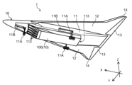
- FIG. 1 is a diagram showing an aircraft equipped with a composite engine according to a first embodiment of the present disclosure.
- FIG. 2 is a perspective view of the aircraft from below.
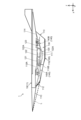
- FIG. 1 is a side view of an aircraft.
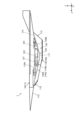
- FIG. 1 is a side view of an aircraft.
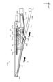
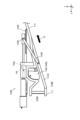
- FIG. FIG. 4 is a side view of the first switching portion in the first position.
- FIG. 4 is a side view of the first switching portion in the second position.
- FIG. FIG. 11 is a side view of the second switching portion in the third position.
- FIG. 13 is a side view of the second switching portion in the fourth position.
- FIG. 2 is a diagram showing an aircraft equipped with a composite engine according to a second embodiment of the present disclosure.
- FIG. 2 is a side cross-sectional view of a first duct portion of the composite engine.
- FIG. 4 is a side cross-sectional view of a second duct portion of the composite engine.
- FIG. 13 is a diagram showing the switching portion in a state where the first inlet is open.
- FIG. 13 is a diagram showing the switching portion in a state where the second inlet is open.
- FIG. 1 is a diagram showing an aircraft equipped with a combined engine according to the first embodiment of the present disclosure.
- Cartesian coordinate system shown in each drawing will be used to explain the structure of the aircraft 1 of this embodiment.
- the X direction is the front-to-rear direction
- the Y direction is the left-to-right direction
- the Z direction is the up-to-down direction.
- aircraft 1 is, for example, a hypersonic aircraft capable of flying in the atmosphere at hypersonic speeds of Mach 5 or more, and has an airframe 10 and a composite engine 100.
- Aircraft 1 has a shape (a so-called wave rider shape) in which shock waves generated at the leading edge of the airframe 10 (wing portion) increase pressure on the underside of the airframe 10, generating a large lift force.
- the aircraft 10 is configured in a roughly triangular shape when viewed from the Z direction, and has a fuselage section 11, main wings 12, control surfaces 13, outer wings 14, and a vertical tail 15.
- the fuselage section 11 is a part that constitutes the fuselage of the aircraft 1, and is located in the center of the aircraft 10 in the Y direction.
- the part of the fuselage section 11 near the end on the positive side in the X direction is the passenger cabin (not shown).
- the part of the fuselage section 11 on the negative side in the X direction of the passenger cabin is a section that stores a fuel tank (not shown). Thermal insulation is provided around the passenger cabin and the fuel tank.
- legs 11A are provided on the negative surface (lower surface) of the fuselage 11 in the Z direction.
- One leg 11A is provided on the positive portion of the fuselage 11 in the X direction, and two legs 11A are provided on the negative portion of the fuselage 11 in the X direction.
- a storage section 11B for storing legs 11A is provided in a portion of the fuselage 11 corresponding to legs 11A.
- Legs 11A are rotatable between a position inside storage section 11B and a position outside storage section 11B, and are stored in storage section 11B while the aircraft 1 is in flight.
- the fuselage 11 has a negative surface (lower surface) in the Z direction on the negative side.
- a surface 11C on the negative surface of the fuselage 11 in the Z direction from the tip of the aircraft 10 to the compound engine 100 (housing 110 described later) is inclined so as to be positioned on the negative side (lower side) in the Z direction as it moves from the tip to the compound engine 100.
- the angle of surface 11C with respect to the X direction is smaller than the angle of a line L connecting the tip of the aircraft 10 and the lower edge of the compound engine 100 (the inlet 112 of the housing 110 described later) with respect to the X direction.
- the main wings 12 are disposed at both ends of the fuselage section 11 in the Y direction.
- the main wings 12 are provided over substantially the entire fuselage section 11 in the X direction.
- the main wings 12 extend from the fuselage section 11 so that the amount of protrusion from the fuselage section 11 increases toward the negative side in the X direction.
- the +Z side surfaces (top surfaces) of the fuselage 11 and main wing 12 are configured to be approximately parallel to the XY plane so as not to interfere with the air (see also Figure 3).
- the control surface 13 is provided at the end (rear end) of the main wing 12 on the negative side in the X direction (see also Figure 2).
- the control surface 13 is provided on the main wing 12 so that the height of the trailing edge is constant in the neutral position.
- the height of the main wing 12 is set so that the height of the trailing edge of the control surface 13 is constant in the neutral position.
- the outer wings 14 adjust the aerodynamic center to maintain the flight attitude of the aircraft 10, and are located on the negative end portion of the Y-direction of each main wing 12 in the X-direction.
- Two vertical tails 15 are provided on the upper surface (the surface on the + side of the main wing 12 in the Z direction) at the rear end (the - side in the X direction) of the main wing 12.
- the two vertical tails 15 are arranged at an incline so that they move away from each other as they approach the + side in the Z direction. This makes it possible to obtain directional stability by preventing the vertical tail 15 from being hidden behind the main wing 12 when viewed from ahead of the airflow when the aircraft 10 flies at a high angle of attack relative to the airflow.
- the compound engine 100 is provided with two types of engines, and is mounted on the negative surface of the fuselage section 11 in the Z direction.
- the compound engine 100 has a housing 110, a first engine 120, a second engine 130, and a switching section 140.
- the first engine 120 is a turbojet engine that corresponds to a first speed range.
- the first speed range may be, for example, a speed range from takeoff (Mach 0) to Mach 5.
- the first engine 120 has a precooler 121, a turbojet 122, and a ram combustor 123.
- the first engine 120 is also provided with a duct 122A that can introduce air into the ram combustor 123 without passing through the turbojet 122. This allows the first engine 120 to operate as a turbo-ramjet as required by the flight plan of the aircraft 1.
- air passing through the inlet 112 is introduced into the scram combustor, and the exhaust gas heated by supersonic combustion in the scram combustor is discharged to the rear of the aircraft 10 through the outlet 113.
- lift is generated on the negative side of the inlet 112 in the X direction of the housing 110 and on the positive side of the outlet 113 in the X direction, pushing the aircraft 10 to the positive side in the Z direction.
- a drag is generated in the inlet 112 portion, pushing the aircraft 10 backward (the negative side in the X direction), and a thrust is generated in the outlet 113 portion, pushing the aircraft 10 forward (the positive side in the X direction).
- the switching unit 140 is provided in the housing 110 and switches the air flow path in the housing 110 between the first flow path 110A and the second flow path 110B.
- the switching unit 140 is configured to be able to switch between opening and closing the first flow path 110A and the second flow path 110B in the housing 110.
- the first flow path 110A is an air flow path corresponding to the first engine 120, and is a flow path corresponding to the space on the + side in the Z direction from the isolation wall 111.
- air is introduced into the first flow path 110A, air is also supplied to the space on the - side in the Z direction from the isolation wall 111.
- the first switching unit 140A is disposed on the + side in the Z direction from the partition wall 111 and on the + side in the X direction from the first engine 120. As shown in FIG. 5, the first switching unit 140A has a rotating member 141A, a guide rail 142A, a slide member 143A, an actuator 144A, a link member 145A, a first opposing member 146, and a second opposing member 147.
- the rotating member 141A is supported at the front end (the end on the positive side in the X direction) of the isolation wall 111 so as to be rotatable about its base end.
- the length of the rotating member 141A is such that its tip contacts the lower edge of the inlet 112. Therefore, when the rotating member 141A is positioned so that its tip contacts the lower edge of the inlet 112 (first position shown in Figures 5 and 6), it causes air to flow into the first flow path 110A.
- the rotating member 141A rotates from the first position toward the positive side (upward) in the Z direction, thereby coming into contact with a first opposing member 146, which will be described later.
- the rotating member 141A when the rotating member 141A is positioned so that its tip comes into contact with the first opposing member 146 (the second position shown in FIG. 7), it closes the first flow path 110A.
- the guide rail 142A is a rail member that extends in the X direction, and is disposed on the positive side of the rotating member 141A in the Z direction in the housing 110, facing the rotating member 141A.
- the guide rail 142A supports the sliding member 143A so that it can slide in the X direction.
- the slide member 143A is connected to the actuator 144A, and slides on the guide rail 142A based on the operation of the actuator 144A.
- the actuator 144A may be of any type, such as a known configuration, as long as it is capable of sliding the slide member 143A.
- the slide member 143A also has three shafts A1, A2, and A3.
- the shafts A1, A2, and A3 are provided so as to protrude from the slide member 143A on both sides in the Y direction.
- the shaft A1 is located on the most positive side in the X direction.
- the shaft A2 is located on the more negative side in the X direction than the shaft A1.
- the shaft A3 is located on the most negative side in the X direction.
- a support member A4 is provided at each tip of the three shaft portions A1, A2, and A3.
- the support members A4 are plate-shaped and are provided on both sides of the slide member 143A in the Y direction.
- the support members A4 support the link member 145A.
- the link member 145A is a member that links the rotating member 141A and the sliding member 143A via the support member A4. One end of the link member 145A is connected to a portion of the support member A4 that is on the negative side of the shaft portion A1 in the Z direction, and the other end is connected to a portion of the rotating member 141A other than the base end and tip end.
- the link member 145A rotates the rotating member 141A in conjunction with the sliding movement of the slide member 143A.
- the sliding movement of the slide member 143A rotates the rotating member 141A between the first position and the second position.
- the first opposing member 146 is formed in a plate shape and is disposed in a position facing the rotating member 141A in the housing 110. Specifically, the base end 146A of the first opposing member 146 is supported at a location on the +X side of the guide rail 142A inside the housing 110, and the first opposing member 146 is rotatable around the base end 146A. The first opposing member 146 is disposed in a position that is inclined so that it is positioned on the -X side as it approaches the -Z side. The tip of the first opposing member 146 is disposed between the rotating member 141A and the slide member 143A. The tip of the first opposing member 146 is provided with a supported portion 146B that is supported by the shaft portion A2.
- the supported portion 146B extends in an inclined direction from the tip of the first opposing member 146 toward the + side of the Z direction so that it is positioned toward the - side of the X direction.
- a long hole 146C is formed in the supported portion 146B.
- the supported portion 146B is supported by the shaft portion A2 as the shaft portion A2 engages with the long hole 146C.
- the first opposing member 146 comes into contact with the rotating member 141A when the rotating member 141A is in the second position. At this time, the tip of the rotating member 141A separates from the lower edge of the inlet 112. This causes the first flow path 110A to be blocked, and air J1 passes under the first opposing member 146 and the rotating member 141A to enter the second flow path 110B.
- the first opposing member 146 can change its posture to follow the rotational movement of the rotating member 141A while being in contact with the rotating member 141A, making it easier to position the rotating member 141A in the desired position.
- the second opposing member 147 is formed in a plate shape and is disposed in a position facing the rotating member 141A in the housing 110. Specifically, the second opposing member 147 is capable of rotating about the base end 147A by being supported at a portion on the negative side of the guide rail 142A in the X direction inside the housing 110. The second opposing member 147 is disposed in an attitude that is inclined so that it is positioned on the positive side of the X direction as it approaches the negative side of the Z direction, and the tip of the second opposing member 147 is positioned between the rotating member 141A and the slide member 143A. The tip of the second opposing member 147 is provided with a supported portion 147B that is supported by the shaft portion A3.
- the supported portion 147B extends from the tip of the second opposing member 147 toward the + side in the Z direction.
- a long hole 147C is formed in the supported portion 147B.
- the supported portion 147B is supported by the shaft portion A3 as the shaft portion A3 engages with the long hole 147C.
- the second opposing member 147 forms part of the first flow path 110A between the rotating member 141A and the second opposing member 147.
- the second opposing member 147 can change its posture, so that even if the rotating member 141A moves from the first position to the second position, the second opposing member 147 can be prevented from interfering with the movement of the rotating member 141A.
- the first opposing member 146 and the second opposing member 147 are positioned so that a second force acts on the slide member 143A in a direction that counteracts the first force acting on the slide member 143A due to the air in the first flow path 110A.
- a force caused by the pressure P1 applied to the rotating member 141A acts on the sliding member 143A.
- a force F1 is applied in the same direction as the pressure P1 (towards the negative side of the Z direction) at the connection part between the rotating member 141A and the link member 145A.
- the force F1 is a force calculated by integrating the area of the pressure P1.
- link member 145A is inclined toward the - side in the X direction as it moves toward the - side in the Z direction, a force F2 is applied to link member 145A in a direction along link member 145A due to force F1.
- a force F3 which is the horizontal component of force F2 (in a direction toward the - side in the X direction) is applied to the connection portion between link member 145A and slide member 143A.
- a horizontal force F3 is applied to slide member 143A due to pressure P1 applied to pivot member 141A.
- the vertical component of force F2 at the connection portion between link member 145A and slide member 143A is restrained by guide rail 142A.
- the first opposing member 146 is arranged in a direction that is inclined so that it is positioned on the negative side of the X direction as it approaches the negative side of the Z direction, the first flow path 110A narrows as it approaches the negative side of the X direction. As a result, the air J1 flowing at supersonic speed through the first flow path 110A is compressed by the shock wave.
- the compressed air flows from the gap on the negative side of the X direction of the first opposing member 146 to the positive side of the Z direction, and pressure P2 is applied to the first opposing member 146 in a direction that narrows the first flow path 110A (a direction that is inclined so that it is positioned on the positive side of the X direction as it approaches the negative side of the Z direction).
- Pressure P2 is the differential pressure applied to both sides of the first opposing member 146.
- a force F4 is applied to the shaft portion A2 of the slide member 143A in a direction parallel to the pressure P2. Therefore, a force F5, which is the horizontal component of the force F4 (towards the +X side) is applied to the shaft portion A2 of the slide member 143A.
- a horizontal force F5 is applied to the slide member 143A due to the pressure P2 applied to the first opposing member 146.
- the force F5 is a force calculated by integrating the area of the pressure P2.
- the vertical component of the force F4 at the shaft portion A2 of the slide member 143A is restrained by the guide rail 142A.
- the force F5 is a force in the opposite direction to the force F3 caused by the pressure P1 acting on the rotating member 141A, and therefore cancels out the force F3.
- the second opposing member 147 is arranged in a direction that is inclined so that it is positioned on the + side of the X direction as it moves toward the - side of the Z direction, the first flow path 110A widens as it moves toward the - side of the X direction.
- a pressure P3 is applied to the second opposing member 147 in a direction that expands the first flow path 110A (a direction that is inclined so that it is positioned on the + side of the X direction as it moves toward the + side of the Z direction).
- Pressure P3 is the differential pressure applied to both sides of the second opposing member 147.
- the supported portion 147B of the second opposing member 147 is in contact with the shaft portion A3 of the slide member 143A, a force F6 parallel to the pressure P3 is applied to the shaft portion A3 of the slide member 143A. Therefore, the horizontal component of the force F6 (direction toward the +X side) F7 is applied to the shaft portion A3 of the slide member 143A. In other words, the horizontal force F7 is applied to the slide member 143A due to the pressure P3 applied to the second opposing member 147.
- the force F7 is a force calculated by integrating the area of the pressure P3.
- the vertical component of the force F6 at the shaft portion A3 of the slide member 143A is restrained by the guide rail 142A.
- a horizontal force F3 is applied to the slide member 143A due to pressure P1 applied to the rotating member 141A.
- forces F5 and F7 that counteract force F3 are applied to the slide member 143A due to pressures P2 and P3 applied to the first opposing member 146 and the second opposing member 147.
- the first opposing member 146 and the second opposing member 147 can reduce the horizontal force F3 applied to the slide member 143A due to the rotating member 141A.
- the second switching unit 140B is disposed on the housing 110 on the positive side in the Z direction of the isolation wall 111 and on the negative side in the X direction of the first engine 120.
- the second switching unit 140B has a rotating member 141B, a guide rail 142B, a slide member 143B, an actuator 144B, a link member 145B, and an opposing member 148.
- the rotating member 141B is supported at the rear end of the isolation wall 111 (the end on the negative side in the X direction) so that it can rotate around the base end.
- a flow path forming wall 114 is provided on the housing 110 on the + side in the Z direction of the isolation wall 111 and the rotating member 141B.
- the flow path forming wall 114 extends from a portion corresponding to a fuel injector 115 provided at the rear end of the isolation wall 111 to the - side in the X direction and is connected to the upper edge of the outlet 113.
- the fuel injector 115 is a portion configured to inject additional fuel into the combustion gas injected from the first engine 120.
- the flow path forming wall 114 is disposed opposite the rotating member 141B, forming part of the first flow path between itself and the rotating member 141B.
- the rotating member 141B opens the first flow path 110A by being rotated to the negative side (lower side) in the Z direction (third position shown in Figures 8 and 9).
- the guide rail 142B is a rail member that extends in the X direction and is disposed on the opposite side of the flow path forming wall 114 from the rotating member 141B.
- the guide rail 142B supports the sliding member 143B so that it can slide in the X direction.
- the slide member 143B is connected to the actuator 144B, and slides on the guide rail 142B based on the operation of the actuator 144B.
- the actuator 144B may be of any type, such as a known configuration, as long as it is capable of sliding the slide member 143B.
- the slide member 143B also has one shaft portion B1.
- the shaft portion B1 protrudes from the slide member 143B on both sides in the Y direction.
- Each tip of the shaft portion B1 supports the link member 145B.
- the link member 145B is a member that links the rotating member 141B and the slide member 143B. One end of the link member 145B is connected to the shaft portion B1, and the other end is connected to a portion of the rotating member 141B other than the base end and the tip end.
- the link member 145B causes the rotating member 141B to rotate in conjunction with the sliding movement of the slide member 143B.
- the sliding movement of the slide member 143B causes the rotating member 141B to rotate between the third position and the fourth position.
- the opposing member 148 is disposed at a position opposing the rotating member 141B, and has a supported portion 148A and an opposing portion 148B.
- the supported portion 148A is rotatably supported by a moving member 149 connected to the actuator 144B.
- the moving member 149 is connected to the linearly moving portion of the actuator 144B together with the sliding member 143B.
- the moving member 149 is located on the + side in the X direction of the sliding member 143B.
- the opposing portion 148B is connected to the supported portion 148A and is positioned opposite the rotating member 141B.
- the surface of the opposing portion 148B facing the rotating member 141B is an inclined surface B2 that inclines toward the + side of the Z direction as it approaches the - side of the X direction.
- the length of the rotating member 141B is such that its tip contacts the flow path forming wall 114. Therefore, when the rotating member 141B is positioned so that its tip contacts the flow path forming wall 114 (fourth position shown in FIG. 10), it blocks the first flow path 110A and forms the wall surface on the +Z direction side of the second flow path 110B.
- the opposing member 148 is positioned so as to apply a second force to the slide member 143B in a direction that counteracts the first force acting on the slide member 143B due to the air in the first flow path 110A.
- the rotating member 141B forms the wall on the negative side of the first flow path 110A in the Z direction, so pressure P4 is applied in the direction toward the negative side in the Z direction.
- Pressure P4 is the differential pressure between the pressures applied to both sides of the rotating member 141B.
- the pressure P4 applied to the rotating member 141B affects the slide member 143A. Specifically, due to the pressure P4, a force F8 is applied in the same direction as the pressure P4 (towards the negative side in the Z direction) at the connection between the rotating member 141B and the link member 145B.
- a force F9 is applied to the link member 145B in a direction that inclines it to be positioned on the + side of the X direction as it approaches the - side of the Z direction due to the force F8.
- a force F10 which is the horizontal component of the force F9 (in the direction toward the + side of the X direction)
- a horizontal force F10 is applied to the slide member 143B due to the pressure P4 applied to the rotating member 141B.
- the force F10 is a force calculated by integrating the area of the pressure P4.
- the vertical component of the force F9 at the connection portion between the link member 145B and the slide member 143B is restrained by the guide rail 142B.
- the surface of the opposing member 148 facing the rotating member 141B is an inclined surface B2 that is inclined toward the positive side of the Z direction as it approaches the negative side of the X direction, so the first flow path 110A widens as it approaches the negative side of the X direction. As a result, pressure P5 is applied by the air flowing through the first flow path 110A.
- a force F11 is applied to the opposing member 148 in a direction parallel to the pressure P5. Furthermore, since the supported portion 148A is in contact with the moving member 149 that is connected to the actuator 144B to which the slide member 143B is connected, a horizontal force F12 is applied to the connection portion with the moving member 149 due to the moment generated around the rotation axis of the opposing member by the force F11. In other words, the horizontal force F12 is applied to the moving member 149 due to the pressure P5 applied to the opposing member 148.
- the force F11 is a force calculated by integrating the area of the pressure P5.
- the force F12 is a force in the opposite direction to the force F10 caused by the pressure P4 acting on the rotating member 141B, and therefore cancels out the force F10.
- a horizontal force F10 is applied to the slide member 143B due to pressure P4 applied to the rotating member 141B.
- a force F12 that counteracts the force F10 is applied to the slide member 143B via the moving member 149 due to pressure P5 applied to the opposing member 148.
- the horizontal force F10 caused by the rotating member 141B and applied to the slide member 143B can be reduced by the opposing member 148.
- the sliding movement of the slide member rotates the rotating member between the first position and the second position, or between the third position and the fourth position.
- the slide member assists the rotational movement of the rotating member, so that the rotating member can be rotated smoothly, and thus the flow path can be switched smoothly.
- the slide member moves on the guide rail and rotates the rotating member via the link member, so the slide member can be moved smoothly while the rotating member can be rotated smoothly in conjunction with the movement.
- the opposing member is arranged so that its position can be changed in accordance with the movement of the sliding member, and therefore can form part of the first flow path in relation to the rotating member, and by changing its position when blocking the first flow path, interference with the movement of the rotating member can be suppressed.
- the opposing member is also positioned in such a way that a second force, based on pressure, acts on the sliding member in a direction that counteracts the first force acting on the sliding member due to the aerodynamic force of the first flow path.
- the opposing member can reduce the horizontal force acting on the sliding member due to the rotating member.
- the surface on the underside of the aircraft 10 from the tip of the aircraft 10 to the compound engine 100 is inclined downward as it moves from the tip to the compound engine 100, so the flow path of the air entering the compound engine 100 becomes narrower by the time it reaches the compound engine 100.
- the angle of the plane on the underside of the aircraft 10 from the tip of the aircraft 10 to the compound engine 100 relative to the horizontal is smaller than the angle of the line connecting the tip of the aircraft 10 and the lower edge of the air inlet 112 in the compound engine 100 relative to the horizontal.
- the angle of the above plane relative to the horizontal can be minimized, allowing the lift from the shock wave to be obtained while minimizing the effects of drag.
- the housing 110 may be set so that the line connecting the tip of the aircraft 10 and the lower edge of the air inlet 112 in the composite engine 100 coincides with the shock wave generated at, for example, the maximum speed or a frequently used speed.
- the first engine 120 and the second engine 130 are stored side by side in the Z direction within the housing 110 with the isolation wall 111 between them.
- the first engine and the second engine may be stored side by side in the X direction within the housing.
- the aircraft 1 according to the second embodiment has an airframe 10 and a compound engine 200.
- the configuration of the aircraft 1 other than the compound engine 200 may be the same as that of the first embodiment.
- the compound engine 200 is housed in an engine housing 10A provided on the negative side of the aircraft 10 in the Z direction. As shown in FIG. 12, the compound engine 200 has a housing 210, a turbojet 220, a ram combustor 230, and a switching unit 240.
- the housing 210 is configured in a cylindrical shape extending in the X direction.
- a turbojet 220 and a ram combustor 230 are housed inside the housing 210.
- the housing 210 is provided with a first duct 211 and a second duct 212.
- the first duct 211 and the second duct 212 are ducts that form a flow path for the air taken into the housing 210, and are configured to extend in the X direction.
- Each of the first duct 211 and the second duct 212 is arranged at different positions in the circumferential direction of the circle that forms the tip surface (end surface in the X direction) of the housing 210 (see also Figures 14 and 15).
- the turbojet 220 is disposed in the center of the housing 210 in the X direction.
- the ram combustor 230 is disposed at the end portion on the negative side of the housing 210 in the X direction.
- the switching unit 240 is disposed at the end portion on the positive side of the housing 210 in the X direction.
- the first duct 211 extends from the switching section 240 towards the turbojet 220, and is a duct capable of introducing air into the turbojet 220.
- the first duct 211 also includes a portion that connects the turbojet 220 to the ram combustor 230.
- the air introduced into the first duct 211 is introduced into the turbojet 220, passes through the ram combustor 230, and is discharged from the end of the housing 210 on the negative side in the X direction.
- the first duct 211 is applied when the turbojet is operating and the speed range of the aircraft 1 is a first speed range (e.g., Mach 0 to Mach 2).
- a rotary generator connected to the turbojet 220 operates to supply power to the aircraft 10.
- the turbojet 220 and the ram combustor 230 correspond to the "first engine” in the second embodiment.
- the first duct 211 corresponds to the "first flow path" in the second embodiment.
- the second duct 212 extends from the switching section 240 directly toward the ram combustor 230, and is a duct that can introduce air directly into the ram combustor 230.
- the air introduced into the second duct 212 passes through the ram combustor 230 and is exhausted from the end of the housing 210 on the negative side in the X direction.
- the second duct 212 is applied when the ramjet is operating and the aircraft 1 is in a second speed range (e.g., Mach 2 to Mach 5).
- a second speed range e.g., Mach 2 to Mach 5.
- electricity is generated by a fuel cell 231 arranged near the ram combustor 230, and power is supplied to the aircraft 10.
- the ram combustor 230 corresponds to the "second engine” in the second embodiment.
- the second duct 212 corresponds to the "second flow path" in the second embodiment.
- the switching unit 240 switches between opening and closing the first air inlet 211A in the first duct 211 and the second air inlet 212A in the second duct 212.
- the switching unit 240 has a rotating member 241 and a sliding member 242.
- the rotating member 241 is a rotatable member and has an inner annular portion 241A, an outer annular portion 241B, and a blocking portion 241C.
- the inner annular portion 241A and the outer annular portion 241B are configured in an annular shape.
- the inner annular portion 241A is disposed inside the outer annular portion 241B and is configured to have a smaller diameter than the outer annular portion 241B.
- the outer annular portion 241B is configured to have approximately the same diameter as the diameter of the circle at the tip of the housing 210.
- the blocking portion 241C connects the inner annular portion 241A and the outer annular portion 241B, and is configured to be able to block either the first inlet 211A or the second inlet 212A.
- a plurality of blocking portions 241C are provided.
- the number of blocking portions 241C is set according to the number of first ducts 211 or the number of second ducts 212.
- first ducts 211 and second ducts 212 are 12 each, the number of blocking sections 241C is set to 12. Note that the number of first ducts 211, second ducts 212, and blocking sections 241C can be appropriately set to a number equal to or greater than 1.
- each blocking portion 241C has a shape in which the central portion of a plate-like member is bent, specifically, a shape that tapers toward the + side in the X direction.
- the force acting on the slide member 242 is offset by each surface and has a sufficiently reduced component in the rotation direction.
- the force acting on the slide member 242 can be sufficiently reduced.
- the multiple blocking sections 241C are each disposed at a position corresponding to the first inlet 211A or the second inlet 212A. Specifically, as shown in FIG. 14, the multiple blocking sections 241C are capable of opening all of the multiple first inlets 211A and blocking all of the multiple second inlets 212A. Also, as shown in FIG. 15, the multiple blocking sections 241C are capable of blocking all of the multiple first inlets 211A and opening all of the multiple second inlets 212A.
- the slide member 242 is, for example, an expandable actuator.
- two slide members 242 are provided.
- the two slide members 242 are arranged symmetrically with respect to the center of the circle that constitutes the rotating member 241.
- the number of slide members 242 can be set appropriately to a number equal to or greater than one. Furthermore, if there are two or more slide members 242, the slide members 242 may be disposed at equal intervals so that a force is applied evenly to the rotating member 241.
- One end 242A of the slide member 242 is connected to the inner annular portion 241A of the rotating member 241.
- the other end 242B of the slide member 242 is connected to, for example, any fixed portion of the housing 210.
- the slide member 242 rotates the rotating member 241 by expanding and contracting one end 242A with the other end 242B as a fulcrum.
- the blocking portion 241C is located at a position (first position) corresponding to the second inlet 212A and blocks the second inlet 212A. Since the first inlet 211A is in an open state, air is introduced into the first duct 211 through the first inlet 211A.
- the blocking portion 241C is located in a position (second position) corresponding to the first inlet 211A and blocks the first inlet 211A. Since the second inlet 212A is in an open state, air is introduced into the second duct 212 through the second inlet 212A.
- the sliding movement of the slide member 242 rotates the rotating member 241 between the first position and the second position. Specifically, when opening the first duct 211, the sliding movement of the slide member 242 rotates the rotating member 241, and the blocking portion 241C moves to a position where it blocks the second duct 212 (second inlet 212A). Also, when opening the second duct 212, the sliding movement of the slide member 242 rotates the rotating member 241, and the blocking portion 241C moves to a position where it blocks the first duct 211 (first inlet 211A).
- the flow path can be switched smoothly with a simple configuration.
- the configuration is capable of sufficiently reducing the force acting on the sliding member 242 due to the pressure acting on the rotating member 241, allowing for smoother switching of the flow path.
- the compound engine 200 according to the second embodiment may also be housed in the housing 110 of the compound engine 100 according to the first embodiment.
- the compound engine 200 may be housed in the space (first flow path 110A) in the housing 110 in which the first engine 120 is housed.
- the aircraft body is configured in a substantially triangular shape, but the present disclosure is not limited to this, and it does not have to be configured in a substantially triangular shape.
- the aircraft is a hypersonic aircraft, but the present disclosure is not limited to this and may be, for example, a supersonic aircraft, an aircraft that is not capable of supersonic speed, etc.
- the device disclosed herein is useful for composite engines and aircraft that can smoothly switch between flow paths.
Landscapes
- Engineering & Computer Science (AREA)
- Aviation & Aerospace Engineering (AREA)
- Chemical & Material Sciences (AREA)
- Combustion & Propulsion (AREA)
- Mechanical Engineering (AREA)
- General Engineering & Computer Science (AREA)
- Structures Of Non-Positive Displacement Pumps (AREA)
- Multiple-Way Valves (AREA)
Abstract
複合エンジンは、第1エンジンと、第2エンジンと、第1流路と、第2流路とを有する流路部と、切替部と、を備え、切替部は、第1流路を開放する第1位置と、第1流路を閉塞する第2位置との間を回動可能な回動部材と、回動部材を第1位置と第2位置との間を回動させるスライド部材と、を有する。
Description
本開示は、複合エンジンおよび航空機に関する。
従来、航空機において、複合エンジンを備えたものが知られている(例えば、特許文献1参照)。複合エンジンは、複数の速度域のそれぞれに対応した複数のエンジンを含む。複合エンジンでは、複数のエンジンのそれぞれの空気流路の開放/閉塞を切り替え可能な可動要素が設けられている。この構成では、可動要素が上下に回動することで、2つの空気流路を切り替えることが可能である。
しかしながら、可動要素には圧力がかかるため、空気流路を切り替える際に、可動要素が圧力の影響により、動作しにくくなり、ひいては流路の切替をスムーズに行うことができないという問題が生じる。特許文献1に記載の構成は、可動要素を回動させる機構について開示されていないので、上記の問題を解決することができない。
本開示の目的は、流路の切替をスムーズに行うことが可能な複合エンジンおよび航空機を提供することである。
本開示に係る複合エンジンは、
航空機に搭載される複合エンジンであって、
第1速度域に対応する第1エンジンと、
前記第1速度域よりも速い第2速度域に対応する第2エンジンと、
前記第1エンジンの空気流路である第1流路と、前記第2エンジンの空気流路である第2流路とを有する流路部と、
前記流路部における前記第1流路の開放/閉塞を切替可能な切替部と、
を備え、
前記切替部は、
前記第1流路を開放する第1位置と、前記第1流路を閉塞する第2位置との間を回動可能な回動部材と、
スライド移動することで、前記回動部材を前記第1位置と前記第2位置との間を回動させるスライド部材と、
を有する。
航空機に搭載される複合エンジンであって、
第1速度域に対応する第1エンジンと、
前記第1速度域よりも速い第2速度域に対応する第2エンジンと、
前記第1エンジンの空気流路である第1流路と、前記第2エンジンの空気流路である第2流路とを有する流路部と、
前記流路部における前記第1流路の開放/閉塞を切替可能な切替部と、
を備え、
前記切替部は、
前記第1流路を開放する第1位置と、前記第1流路を閉塞する第2位置との間を回動可能な回動部材と、
スライド移動することで、前記回動部材を前記第1位置と前記第2位置との間を回動させるスライド部材と、
を有する。
本開示に係る航空機は、
機体と、
前記機体の下面に設けられる、上記の複合エンジンと、
を備え、
前記機体の下面における前記機体の先端部から前記複合エンジンまでの面は、前記先端部から前記複合エンジンに向かうにつれ下に位置するように傾斜している。
機体と、
前記機体の下面に設けられる、上記の複合エンジンと、
を備え、
前記機体の下面における前記機体の先端部から前記複合エンジンまでの面は、前記先端部から前記複合エンジンに向かうにつれ下に位置するように傾斜している。
本開示によれば、流路の切替をスムーズに行うことができる。
以下、本開示の第1の実施の形態を図面に基づいて詳細に説明する。図1は、本開示の第1の実施の形態に係る複合エンジンを備えた航空機を示す図である。また、本実施の形態の航空機1の構造を説明するにあたり、各図に示す直交座標系を使用する。航空機1は、例えば、地上に位置した際に、X方向が前後方向、Y方向が左右方向、Z方向が上下方向となるように配置される。
図1に示すように、航空機1は、例えば、大気中をマッハ5以上の極超音速で飛行可能な極超音速機であり、機体10と、複合エンジン100とを有する。航空機1は、機体10(主翼部分)の前縁で発生する衝撃波によって、機体10の下面の圧力が上昇して大きな揚力を発生する形状(いわゆるウェーブライダー形状)を有する。
機体10は、Z方向から見て、略三角形状に構成されており、胴体部11と、主翼12と、操舵翼13と、外翼14と、垂直尾翼15とを有する。
胴体部11は、航空機1の胴体を構成する部分であり、機体10のY方向の中央部分に位置している。胴体部11におけるX方向の+側の端部付近の部分は、客室(不図示)である。胴体部11における客室よりもX方向の-側の部分は、燃料タンクを格納する部分(不図示)である。客室および燃料タンクの周囲には、断熱材が設けられる。
図2に示すように、胴体部11のZ方向の-側の面(下面)には、脚部11Aが設けられている。脚部11Aは、胴体部11のX方向の+側の部分に1つ、胴体部11のX方向の-側の部分に2つ、設けられている。また、胴体部11の脚部11Aに対応する部分には、脚部11Aを格納するための格納部11Bが設けられている。脚部11Aは、格納部11B内の位置と、格納部11B外の位置との間で回動可能となっており、航空機1の飛行中は、格納部11B内に格納される。
また、胴体部11のZ方向の-側の面(下面)には、複合エンジン100が設けられている。また、図3に示すように、胴体部11のZ方向の-側の面における、機体10の先端部から複合エンジン100(後述する筐体110)までの面11Cは、先端部から複合エンジン100に向かうにつれZ方向の-側(下側)に位置するように傾斜している。具体的には、面11CにおけるX方向(水平方向)に対する角度は、機体10の先端部と、複合エンジン100(後述する筐体110の流入口112)の下縁部とを結ぶ線Lの、X方向に対する角度より小さくなっている。
図1に示すように、主翼12は、胴体部11のY方向の両端部に配置される。主翼12は、胴体部11のX方向の略全体にわたって設けられている。主翼12は、X方向の-側に向かうにつれ、胴体部11からの突出量が大きくなるように、胴体部11から延びて構成されている。
また、胴体部11および主翼12のZ方向の+側の面(上面)は、空気と干渉しないように、XY平面と略平行になるように構成されている(図3も参照)。
操舵翼13は、主翼12のX方向の-側の端部(後端)に設けられている(図2も参照)。操舵翼13は、中立位置で後縁の高さが一定となるように、主翼12に設けられている。言い換えると、中立位置で操舵翼13の後縁の高さが一定となるように、主翼12の高さが設定されている。
外翼14は、空力中心を調整して機体10の飛行姿勢を維持するものであり、各主翼12のY方向の端部における、X方向の-側の端部部分に設けられている。
垂直尾翼15は、主翼12の後端部(X方向の-側)における、上面(主翼12のZ方向の+側の面)に2つ設けられている。2つの垂直尾翼15は、Z方向の+側に向かうにつれ、互いに離れるように傾斜してそれぞれ配置されている。これにより、機体10が気流に対して高い迎角で飛行する際、気流前方から見て垂直尾翼15が主翼12の背後に隠れないようにして方向安定性を得ることが可能となる。
図3に示すように、複合エンジン100は、2種類のエンジンが設けられており、胴体部11のZ方向の-側の面に設けられている。複合エンジン100が胴体部11のZ方向の-側の面(下面)に設けられることで、当該下面に発生した衝撃波によって圧力が高まった空気を複合エンジン100に取り込むことが可能となり、ひいてはエンジンの推力を増大させることができる。複合エンジン100は、筐体110と、第1エンジン120と、第2エンジン130と、切替部140とを有する。
筐体110は、第1エンジン120および第2エンジン130を収納している。筐体110の内部には、隔離壁111が設けられている。隔離壁111は、第1エンジン120と第2エンジン130とを隔離するためのものである。隔離壁111に対してZ方向の+側の空間には、第1エンジン120が配置され、隔離壁111に対してZ方向の-側の空間には、第2エンジン130が配置されている。
筐体110のX方向の+側には、第1エンジン120または第2エンジン130に向かう空気の流入口112が設けられている。筐体110のX方向の-側には、第1エンジン120または第2エンジン130から排出される空気の流出口113が設けられている。筐体110における流入口112および流出口113付近には、可動壁が装着されており、飛行速度に応じて最適な空気流入および燃焼ガス排出を行うことが可能である。
第1エンジン120は、第1速度域に対応するターボジェットエンジンである。第1速度域は、例えば、離陸(マッハ0)からマッハ5までの速度域であっても良い。第1エンジン120は、予冷器121と、ターボジェット122と、ラム燃焼器123とを有する。
予冷器121は、ターボジェット122よりもX方向の+側に設けられている。この予冷器121により、航空機1の高速飛行時の空力加熱を緩和することができ、ひいては、第1速度域の範囲における連続作動が可能となっている。
ラム燃焼器123は、ターボジェット122よりもX方向の-側に設けられている。第1エンジン120では、流入口112から流入した空気が、予冷器121、ターボジェット122およびラム燃焼器123を経由して流出口113から排出されるようになっている。
また、第1エンジン120には、ターボジェット122を経由せずに、ラム燃焼器123に空気を導入可能なダクト122Aが設けられている。これにより、航空機1の飛行計画の必要に応じて、ターボ・ラムジェットとして作動することが可能である。
第2エンジン130は、第1エンジン120とは異なる速度域(第2速度域)に対応するスクラムジェットエンジンである。第2速度域は、例えば、マッハ5以上の速度域であっても良い。第2エンジン130は、例えば、公知の構成であっても良い。
第2エンジン130では、流入口112を通過した空気がスクラム燃焼器に導入され、スクラム燃焼器で超音速燃焼によって高温となった排気ガスが、流出口113を通過して機体10の後方に排出される。このとき、筐体110の流入口112のX方向の-側および流出口113のX方向の+側部分には、機体10をZ方向の+側に押す揚力が発生する。また、流入口112部分には、機体10を後方(X方向の-側)に押す抗力が発生し、流出口113部分には、機体10を前方(X方向の+側)に押す推力が発生する。この場合、スクラム燃焼器での超音速燃焼によって、圧力が高まっているので、流入口112における抗力よりも、流出口113における推力が大きくなることにより、機体10全体をX方向の+側に押す推力が発生する。
切替部140は、筐体110内に設けられ、筐体110における空気流路を第1流路110Aと、第2流路110Bとの何れかに切り替える。つまり、切替部140は、筐体110における第1流路110Aと第2流路110Bとの間の開放/閉塞を切替可能に構成されている。
第1流路110Aは、第1エンジン120に対応する空気流路であり、隔離壁111よりもZ方向の+側の空間に対応する流路である。第1流路110Aに空気を導入する場合、隔離壁111よりもZ方向の-側の空間にも空気が供給される状態となる。
第2流路110Bは、第2エンジン130に対応する空気流路であり、隔離壁111よりもZ方向の-側の空間に対応する流路である。第2流路110Bに空気を導入して第2エンジン130を作動させる場合、図4に示すように、隔離壁111よりもZ方向の+側の空間は、切替部140により、流入口112に対して閉塞された状態となる。筐体110は、本開示の「流路部」に対応する。
切替部140は、第1切替部140Aと、第2切替部140Bとを有する。第1切替部140Aは、筐体110の流入口112のX方向の+側に設けられ、流入口112から流入する空気を第1流路110Aに流すか第2流路に流すかを選択できるように構成されている。第2切替部140Bは、筐体110の流出口113に設けられ、流出口113のZ方向の上側に流出する空気流路を第1流路および第2流路の何れかに切替可能に構成されている。
まず、第1切替部140Aの詳細について説明する。
第1切替部140Aは、隔離壁111よりもZ方向の+側、かつ、第1エンジン120よりもX方向の+側に配置されている。図5に示すように、第1切替部140Aは、回動部材141Aと、ガイドレール142Aと、スライド部材143Aと、アクチュエータ144Aと、リンク部材145Aと、第1対向部材146と、第2対向部材147と、を有する。
回動部材141Aは、隔離壁111の前端部(X方向の+側の端部)において、基端部を中心に回動可能に支持されている。回動部材141Aの長さは、先端部が流入口112の下縁部と接触する程度の長さである。そのため、回動部材141Aは、先端部が流入口112の下縁部と接触する位置(図5、図6に示す第1位置)に配置された際、第1流路110Aに空気を流入させる。
また、回動部材141Aは、第1位置よりZ方向の+側(上側)に回動することにより、後述する第1対向部材146と接触する。言い換えると、回動部材141Aは、先端部が第1対向部材146と接触する位置(図7に示す第2位置)に配置された際、第1流路110Aを閉塞する。
ガイドレール142Aは、X方向に延びるレール部材であり、筐体110における回動部材141AよりもZ方向の+側で、回動部材141Aと対向する位置に配置されている。ガイドレール142Aは、スライド部材143AをX方向にスライド移動可能に支持する。
スライド部材143Aは、アクチュエータ144Aに接続されており、アクチュエータ144Aの動作に基づいて、ガイドレール142A上をスライド移動する。アクチュエータ144Aは、例えば、公知の構成等、スライド部材143Aをスライド移動可能な構成である限り、どのようなものであっても良い。
また、スライド部材143Aは、3つの軸部A1,A2,A3を有する。軸部A1,A2,A3は、スライド部材143AからY方向の両側にそれぞれ突出して設けられている。軸部A1は、3つの軸部A1,A2,A3のうち、X方向において最も+側に位置する。軸部A2は、軸部A1よりもX方向の-側に位置する。軸部A3は、3つの軸部A1,A2,A3のうち、X方向において最も-側に位置する。
3つの軸部A1,A2,A3の各先端部には、支持部材A4が設けられている。支持部材A4は、板状に構成されており、スライド部材143AのY方向の両側のそれぞれに設けられている。支持部材A4は、リンク部材145Aを支持する。
リンク部材145Aは、支持部材A4を介して、回動部材141Aとスライド部材143Aとをリンクする部材である。リンク部材145Aは、一端が、支持部材A4における、軸部A1よりもZ方向の-側の部位に接続され、他端が、回動部材141Aの基端部および先端部以外の部位に接続されている。
リンク部材145Aにより、スライド部材143Aのスライド移動に連動して、回動部材141Aが回動する。すなわち、スライド部材143Aは、スライド移動することで、回動部材141Aを第1位置と第2位置との間を回動させる。
具体的には、図6に示すように、スライド部材143Aが、ガイドレール142Aにおける、X方向の最も-側に位置する場合、回動部材141Aは、第1位置に位置する。図7に示すように、スライド部材143Aが、ガイドレール142Aにおける、X方向の最も-側の位置からX方向の+側に移動すると、回動部材141Aは、リンク部材145Aにより、第1位置からZ方向の+側に回動して、第2位置に移動する。
第1対向部材146は、板状に構成されており、筐体110における回動部材141Aと対向する位置に配置される。具体的には、第1対向部材146は、筐体110内のガイドレール142AよりもX方向の+側の部位に基端部146Aが支持され、基端部146Aを中心に回動可能である。また、第1対向部材146は、Z方向の-側に向かうにつれX方向の-側に位置するように傾斜した方向に沿った姿勢で配置されている。第1対向部材146の先端部は、回動部材141Aと、スライド部材143Aとの間に位置する。第1対向部材146の先端部には、軸部A2に支持される被支持部146Bが設けられる。
被支持部146Bは、第1対向部材146の先端部から、Z方向の+側に向かうにつれX方向の-側に位置するように傾斜した方向に延びている。被支持部146Bには、長孔146Cが形成されている。被支持部146Bは、軸部A2と長孔146Cとが係合することで、軸部A2に支持される。
また、スライド部材143Aがスライド移動すると、長孔146C内を軸部A2がスライドするので、スライド部材143Aのスライド移動に伴い、第1対向部材146の姿勢が変更される。
具体的には、図6に示すように、第1対向部材146は、回動部材141Aが第1位置に位置する場合、回動部材141Aと離間している。これにより、第1流路110Aが開放されるので、第1対向部材146と回動部材141Aとの間を空気J1が通過して、第1流路110Aに入り込む。この場合、長孔146Cの上縁と、軸部A2とが係合した状態となっている。また、この状態において、回動部材141AのZ方向の―側を通過する空気が第2流路110Bに流入する。
このように、回動部材141Aが第1位置に位置する場合、第1対向部材146は、回動部材141Aとの間で、第1流路110Aの一部を構成する。
また、図7に示すように、第1対向部材146は、回動部材141Aが第2位置に位置する場合、回動部材141Aと接触する。この際、回動部材141Aの先端部が、流入口112の下縁部と離間する。これにより、第1流路110Aが閉塞され、第1対向部材146および回動部材141Aの下方を空気J1が通過して、第2流路110Bに入り込む。
この場合、長孔146Cの下縁と、軸部A2とが係合した状態となり、第1対向部材146の姿勢が、図6に示す位置よりも、Z方向の+側に回動した状態となる。つまり、第1対向部材146の姿勢は、回動部材141Aの回動動作に倣う側に変更される。
このように、回動部材141Aが第2位置に位置する場合、第1対向部材146が回動部材141Aと接触しつつ、回動部材141Aの回動動作に倣う側に姿勢を変更可能であるので、所望の位置に回動部材141Aを位置させやすくすることができる。
第2対向部材147は、板状に構成されており、筐体110における回動部材141Aと対向する位置に配置される。具体的には、第2対向部材147は、筐体110内のガイドレール142AよりもX方向の-側の部位に基端部147Aが支持されることで、基端部147Aを中心に回動可能である。第2対向部材147は、Z方向の-側に向かうにつれX方向の+側に位置するように傾斜した方向に沿った姿勢で配置されており、第2対向部材147の先端部が、回動部材141Aと、スライド部材143Aとの間に位置する。第2対向部材147の先端部には、軸部A3に支持される被支持部147Bが設けられる。
被支持部147Bは、第2対向部材147の先端部から、Z方向の+側に延びている。被支持部147Bには、長孔147Cが形成されている。被支持部147Bは、軸部A3と長孔147Cとが係合することで、軸部A3に支持される。
また、スライド部材143Aがスライド移動すると、長孔147C内を軸部A3がスライドするので、スライド部材143Aのスライド移動に伴い、第2対向部材147の姿勢が変更される。
具体的には、図6に示すように、第2対向部材147は、回動部材141Aが第1位置に位置する場合、回動部材141Aと離間している。これにより、第2対向部材147と回動部材141Aとの間を空気J1が、通過して、第1流路110Aのさらに奥に入り込む。この場合、長孔147Cの上縁と、軸部A3とが係合した状態となっている。
このように、回動部材141Aが第1位置に位置する場合、第2対向部材147は、回動部材141Aとの間で、第1流路110Aの一部を構成する。
また、図7に示すように、第2対向部材147は、回動部材141Aが第2位置に位置する場合、回動部材141Aの上方に位置する。この場合、長孔147Cの下縁と、軸部A3とが係合した状態となっている。
このように、回動部材141Aが第2位置に位置する場合、第2対向部材147が姿勢を変更可能であるので、回動部材141Aが第1位置から第2位置に移動しても、第2対向部材147が回動部材141Aの移動を干渉することを抑制することができる。
また、図6に示すように、第1対向部材146および第2対向部材147は、第1流路110Aの空気に起因してスライド部材143Aにかかる第1力を打ち消す方向の第2力を、スライド部材143Aに作用させる姿勢で配置される。
第1対向部材146および第2対向部材147のそれぞれと、回動部材141Aとで、第1流路110Aの一部を構成するので、各部材には、第1流路110Aに入り込む空気J1に起因した圧力がかかる。回動部材141Aは、第1流路110AのZ方向の-側の壁を構成するため、回動部材141Aには、Z方向の-側に向かう方向に圧力P1がかかる。圧力P1は、回動部材141Aの両面に係る圧力の差圧である。
回動部材141Aはリンク部材145Aを介してスライド部材143Aと接続されているので、回動部材141Aにかかる圧力P1に起因した力がスライド部材143Aに作用する。具体的には、圧力P1に起因して、回動部材141Aとリンク部材145Aとの接続部分において、圧力P1と同じ方向(Z方向の-側に向かう方向)に力F1がかかる。力F1は、圧力P1の面積積分によって求まる力である。
この場合、リンク部材145Aは、Z方向の-側に向かうにつれ、X方向の-側に位置するように傾斜しているため、リンク部材145Aには、力F1に起因して、リンク部材145Aに沿った方向の力F2がかかる。これにより、リンク部材145Aと、スライド部材143Aとの接続部分には、力F2の水平方向成分(X方向の-側に向かう方向)の力F3がかかることになる。つまり、回動部材141Aにかかる圧力P1に起因して、スライド部材143Aに水平方向の力F3がかかる。なお、リンク部材145Aと、スライド部材143Aとの接続部分における、力F2の垂直成分は、ガイドレール142Aで拘束される。
また、第1対向部材146は、Z方向の-側に向かうにつれX方向の-側に位置するように傾斜した方向に沿って配置されているため、第1流路110Aが、X方向の-側に向かうにつれ狭まる。その結果、第1流路110Aを超音速で流れる空気J1が衝撃波によって圧縮される。この空気J1の圧縮に起因して、圧縮された空気が第1対向部材146のX方向-側の隙間からZ方向+側に流入することで、第1対向部材146には、第1流路110Aを縮小する方向(Z方向の-側に向かうにつれX方向の+側に位置するように傾斜した方向)の圧力P2がかかる。圧力P2は、第1対向部材146の両面にかかる圧力の差圧である。
また、第1対向部材146は、被支持部146Bが、スライド部材143Aの軸部A2と接しているので、スライド部材143Aの軸部A2の部分に、圧力P2と平行な方向の力F4がかかる。そのため、スライド部材143Aの軸部A2の部分には、力F4の水平方向成分(X方向の+側に向かう方向)の力F5がかかることになる。つまり、第1対向部材146にかかる圧力P2に起因して、スライド部材143Aに水平方向の力F5がかかる。力F5は、圧力P2の面積積分によって求まる力である。なお、スライド部材143Aの軸部A2の部分における、力F4の垂直成分は、ガイドレール142Aで拘束される。
力F5は、回動部材141Aにかかる圧力P1に起因する力F3とは逆向きの力であるので、力F3を打ち消す力である。
また、第2対向部材147は、Z方向の-側に向かうにつれX方向の+側に位置するように傾斜した方向に沿って配置されているため、第1流路110Aが、X方向の-側に向かうにつれ広がる。その結果、第1流路110Aを流れる音速以下の空気J1の速度が低下し、圧力が上昇する。この空気J1の圧力上昇に起因して、第2対向部材147には、第1流路110Aを拡大する方向(Z方向の+側に向かうにつれX方向の+側に位置するように傾斜した方向)の圧力P3がかかる。圧力P3は、第2対向部材147の両面にかかる圧力の差圧である。
また、第2対向部材147は、被支持部147Bが、スライド部材143Aの軸部A3と接しているので、スライド部材143Aの軸部A3の部分に、圧力P3と平行な力F6がかかる。そのため、スライド部材143Aの軸部A3の部分には、力F6の水平方向成分(X方向の+側に向かう方向)のF7がかかることになる。つまり、第2対向部材147にかかる圧力P3に起因して、スライド部材143Aに水平方向の力F7がかかる。力F7は、圧力P3の面積積分によって求まる力である。なお、スライド部材143Aの軸部A3の部分における、力F6の垂直成分は、ガイドレール142Aで拘束される。
力F7は、回動部材141Aにかかる圧力P1に起因する力F3とは逆向きの力であるので、力F3を打ち消す力である。
以上のことから、第1切替部140Aでは、回動部材141Aにかかる圧力P1に起因して、スライド部材143Aに水平方向の力F3がかかる。その一方、第1対向部材146および第2対向部材147にかかる圧力P2,P3に起因して、スライド部材143Aに力F3を打ち消す力F5,F7がかかる。すなわち、第1対向部材146および第2対向部材147により、スライド部材143Aにかかる、回動部材141Aに起因した水平方向の力F3を低減することができる。
次に、第2切替部140Bの詳細について説明する。
図3に示すように、第2切替部140Bは、筐体110における、隔離壁111よりもZ方向の+側、かつ、第1エンジン120よりもX方向の-側に配置されている。図8に示すように、第2切替部140Bは、回動部材141Bと、ガイドレール142Bと、スライド部材143Bと、アクチュエータ144Bと、リンク部材145Bと、対向部材148と、を有する。
回動部材141Bは、隔離壁111の後端部(X方向の-側の端部)において、基端部を中心に回動可能に支持されている。
また、筐体110における、隔離壁111および回動部材141BよりもZ方向の+側には、流路形成壁114が設けられている。流路形成壁114は、隔離壁111の後端部に設けられる燃料噴射器115に対応する部分から、X方向の-側に延びて、流出口113の上縁に接続される。燃料噴射器115は、第1エンジン120から噴射される燃焼ガスに更に燃料を噴射するために構成された部分である。
流路形成壁114は、回動部材141Bと対向して配置されることで、回動部材141Bとの間で、第1流路の一部を構成する。
また、回動部材141Bは、Z方向の-側(下側)に回動した位置(図8、図9に示す第3位置)に配置することで、第1流路110Aを開放する。
ガイドレール142Bは、X方向に延びるレール部材であり、流路形成壁114における、回動部材141Bとは反対側に配置されている。ガイドレール142Bは、スライド部材143BをX方向にスライド移動可能に支持する。
スライド部材143Bは、アクチュエータ144Bに接続されており、アクチュエータ144Bの動作に基づいて、ガイドレール142B上をスライド移動する。なお、アクチュエータ144Bは、例えば、公知の構成等、スライド部材143Bをスライド移動可能な構成である限り、どのようなものであっても良い。
また、スライド部材143Bは、1つの軸部B1を有する。軸部B1は、スライド部材143BからY方向の両側にそれぞれ突出して設けられている。軸部B1の各先端部は、リンク部材145Bを支持する。
リンク部材145Bは、回動部材141Bとスライド部材143Bとをリンクする部材である。リンク部材145Bは、一端が、軸部B1に接続され、他端が、回動部材141Bの基端部および先端部以外の部位に接続されている。
リンク部材145Bにより、スライド部材143Bのスライド移動に連動して、回動部材141Bが回動する。すなわち、スライド部材143Bは、スライド移動することで、回動部材141Bを第3位置と第4位置との間を回動させる。
具体的には、図9に示すように、スライド部材143Bが、ガイドレール142Bにおける、X方向の+側の端部付近に位置する場合、回動部材141Bは、第3位置に位置する。これにより、第1流路110Aが開放され、燃料噴射器115の隙間を通過した空気J2が筐体110の外部に排出される。
また、スライド部材143Bが、ガイドレール142Bにおける、X方向の+側の端部付近の位置(図9に示す位置)からX方向の-側の端部付近の位置(図10に示す位置)に移動すると、図10に示すように、回動部材141Bは、リンク部材145Bにより、第3位置からZ方向の+側に回動して、第4位置に移動する。これにより、第2流路110Bを流れる空気J3が、回動部材141Bの下方を通過して、筐体110の外部に排出される。
対向部材148は、回動部材141Bと対向する位置に配置され、被支持部148Aと、対向部148Bとを有する。被支持部148Aは、アクチュエータ144Bに接続された移動部材149に回動可能に支持されている。移動部材149は、アクチュエータ144Bの直線移動する部分にスライド部材143Bとともに接続されている。移動部材149は、スライド部材143BよりもX方向の+側に位置している。
対向部148Bは、被支持部148Aに接続され、回動部材141Bと対向する位置に配置される。対向部148Bの回動部材141Bとの対向面は、X方向の-側に向かうにつれ、Z方向の+側に位置するように傾斜する傾斜面B2となっている。
回動部材141Bが第3位置に位置する際、回動部材141Bと傾斜面B2とで第1流路110Aの一部を構成する。
回動部材141Bの長さは、先端部が流路形成壁114と接触する程度の長さである。そのため、回動部材141Bは、先端部が流路形成壁114と接触する位置(図10に示す第4位置)に配置された際、第1流路110Aを閉塞するとともに、第2流路110BのZ方向+側の壁面を構成する。
また、図10に示すように、移動部材149がスライド部材143BとともにX方向の-側に移動すると、対向部148Bが被支持部148Aを中心にZ方向の+側およびX方向の+側に回動する。すなわち、対向部材148の姿勢が変更される。
このように、回動部材141Bが第1流路110Aを閉塞する側に移動しても、対向部材148が姿勢を変更するので、対向部材148が回動部材141Bの移動を干渉することを抑制することができる。
また、対向部材148は、第1流路110Aの空気に起因してスライド部材143Bにかかる第1力を打ち消す方向の第2力を、スライド部材143Bに作用させる姿勢で配置される。
図9に示すように、回動部材141Bには、第1流路110AのZ方向の-側の壁を構成するため、Z方向の-側に向かう方向に圧力P4がかかる。圧力P4は、回動部材141Bの両面にかかる圧力の差圧である。
回動部材141Bはリンク部材145Bを介してスライド部材143Bと接続されているので、回動部材141Bにかかる圧力P4がスライド部材143Aに影響する。具体的には、圧力P4に起因して、回動部材141Bとリンク部材145Bとの接続部分において、圧力P4と同じ方向(Z方向の-側に向かう方向)に力F8がかかる。
この場合、リンク部材145Bは、Z方向の-側に向かうにつれ、X方向の+側に位置するように傾斜しているため、リンク部材145Bには、力F8に起因して、Z方向の-側に向かうにつれ、X方向の+側に位置するように傾斜した方向の力F9がかかる。これにより、リンク部材145Bと、スライド部材143Bとの接続部分には、力F9の水平方向成分(X方向の+側に向かう方向)の力F10がかかることになる。つまり、回動部材141Bにかかる圧力P4に起因して、スライド部材143Bに水平方向の力F10がかかる。力F10は、圧力P4の面積積分によって求まる力である。なお、リンク部材145Bと、スライド部材143Bとの接続部分における、力F9の垂直成分は、ガイドレール142Bで拘束される。
また、対向部材148の回動部材141Bとの対向面は、X方向の-側に向かうにつれ、Z方向の+側に位置するように傾斜する傾斜面B2であるため、第1流路110Aが、X方向の-側に向かうにつれ広がる。その結果、第1流路110Aを流れる空気の圧力P5がかかる。
また、対向部材148には、圧力P5と平行な方向の力F11がかかる。また、被支持部148Aが、スライド部材143Bが接続されたアクチュエータ144Bに接続された移動部材149と接しているので、移動部材149との接続部分に、力F11によって対向部材の回転軸周りに発生するモーメントを受けて水平方向の力F12がかかることになる。つまり、対向部材148にかかる圧力P5に起因して、移動部材149に水平方向の力F12がかかる。力F11は、圧力P5の面積積分によって求まる力である。
力F12は、回動部材141Bにかかる圧力P4に起因する力F10とは逆向きの力であるので、力F10を打ち消す力である。
以上のことから、第2切替部140Bでは、回動部材141Bにかかる圧力P4に起因して、スライド部材143Bに水平方向の力F10がかかる。その一方、対向部材148にかかる圧力P5に起因して、移動部材149を介して、スライド部材143Bに力F10を打ち消す力F12がかかる。すなわち、対向部材148により、スライド部材143Bにかかる、回動部材141Bに起因した水平方向の力F10を低減することができる。
以上のように構成された第1の実施の形態によれば、スライド部材がスライド移動することで、回動部材を第1位置と第2位置との間、または第3位置と第4位置の間を回動させる。すなわち、スライド部材が回動部材の回動動作をアシストするので、回動部材をスムーズに回動させることができ、ひいては流路の切替をスムーズに行うことができる。
また、スライド部材が、ガイドレール上を移動し、かつ、リンク部材を介して、回動部材を回動させるので、スライド部材をスムーズに移動させつつ、その移動に連動して回動部材をスムーズに回動させることができる。
また、対向部材は、スライド部材の移動に伴い姿勢変更可能に設けられるので、回動部材との関係で、第1流路の一部を構成することができ、かつ、第1流路を閉塞する際に姿勢を変更させることで回動部材の移動を干渉することを抑制することができる。
また、対向部材は、第1流路の空気力に起因してスライド部材にかかる第1力を打ち消す方向の第2力を、圧力に基づいてスライド部材に作用させる姿勢で配置される。その結果、対向部材により、スライド部材にかかる、回動部材に起因した水平方向の力を低減することができる。
また、機体10の下面における機体10の先端部から複合エンジン100までの面が、先端部から複合エンジンに向かうにつれ下に位置するように傾斜しているので、複合エンジン100に入り込む空気の流路が、複合エンジン100に到達するまでに狭くなる。
そのため、複合エンジン100の筐体110に入り込む空気を圧縮することができる。
ところで、機体10の前縁で発生する衝撃波によって空気の圧力が高まることにより、機体10の下面が揚力を受けることができる一方、下面の傾斜角が比較的大きいと、衝撃波に基づく抗力の影響を受ける可能性がある。
本実施の形態では、機体10の下面における機体10の先端部から複合エンジン100までの面における水平方向に対する角度が、機体10の先端部と、複合エンジン100における空気の流入口112の下縁部とを結ぶ線の、水平方向に対する角度より小さい。
つまり、上記の面における水平方向に対する角度を最低限に抑えることができるので、衝撃波に基づく揚力の恩恵を受けつつ、抗力の影響を最低限に抑えることができる。
また、機体10の前縁で発生する衝撃波が、複合エンジン100における流入口112の下縁部に当たる場合、複合エンジン100における空気の流入の効率が良好になる。しかし、航空機1の速度に応じて発生する衝撃波の角度(方向)は異なるものとなる。そのため、機体10の先端部と、複合エンジン100における空気の流入口112の下縁部とを結ぶ線が、例えば、最高速度や利用頻度の高い速度で発生する衝撃波と一致するように、筐体110を設定しても良い。
次に、本開示の第2の実施の形態について説明する。第1の実施の形態では、第1エンジン120と第2エンジン130とが、筐体110内で、隔離壁111を介してZ方向に並んで収納されていた。第2の実施の形態では、第1エンジンおよび第2エンジンが筐体内で、X方向に並んで収納されていても良い。
図11に示すように、第2の実施の形態に係る航空機1は、機体10と、複合エンジン200とを有する。航空機1は、複合エンジン200以外の構成は、第1の実施の形態と同様であっても良い。
複合エンジン200は、機体10のZ方向の-側の面に設けられたエンジン筐体部10Aに格納されている。図12に示すように、複合エンジン200は、筐体210と、ターボジェット220と、ラム燃焼器230と、切替部240とを有する。
筐体210は、X方向に延びる筒状に構成されている。筐体210の内部には、ターボジェット220およびラム燃焼器230が収納されている。また、図12および図13に示すように、筐体210には、第1ダクト211と、第2ダクト212とが設けられている。
第1ダクト211および第2ダクト212は、筐体210に取り込んだ空気の流路を構成するダクトであり、X方向に延びて構成される。第1ダクト211および第2ダクト212のそれぞれは、筐体210の先端面(X方向の端面)を構成する円の周方向において異なる位置に配置されている(図14および図15も参照)。第1ダクト211および第2ダクト212のそれぞれは、複数設けられており、第1ダクト211と第2ダクト212とが交互に並ぶように配置されている。
ターボジェット220は、X方向において筐体210の中央部分に配置されている。ラム燃焼器230は、X方向において筐体210の-側の端部部分に配置されている。また、切替部240は、X方向において筐体210の+側の端部部分に配置されている。
第1ダクト211は、切替部240から、ターボジェット220に向けて延びており、ターボジェット220に空気を導入可能なダクトである。また、第1ダクト211は、ターボジェット220からラム燃焼器230に接続される部分を含む。つまり、第1ダクト211に導入された空気は、ターボジェット220に導入され、ラム燃焼器230を経由して、筐体210のX方向の-側の端部から排出される。
第1ダクト211は、航空機1の速度域が第1速度域(例えば、マッハ0~マッハ2)である、ターボジェット作動時に適用される。ターボジェット作動時は、ターボジェット220に接続された回転式発電機が作動して、機体10に電力が供給される。ターボジェット220およびラム燃焼器230は、第2の実施の形態における「第1エンジン」に対応する。第1ダクト211は、第2の実施の形態における「第1流路」に対応する。
第2ダクト212は、切替部240から、直接ラム燃焼器230に向けて延びており、ラム燃焼器230に直接空気を導入可能なダクトである。第2ダクト212に導入された空気は、ラム燃焼器230を経由して、筐体210のX方向の-側の端部から排出される。
第2ダクト212は、航空機1の速度域が第2速度域(例えば、マッハ2~マッハ5)である、ラムジェット作動時に適用される。ラムジェット作動時は、ラム燃焼器230付近に配置された燃料電池231で発電して、機体10に電力が供給される。ラム燃焼器230は、第2の実施の形態における「第2エンジン」に対応する。第2ダクト212は、第2の実施の形態における「第2流路」に対応する。
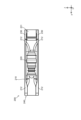
図14に示すように、切替部240は、第1ダクト211における空気の第1流入口211Aと、第2ダクト212における空気の第2流入口212Aとの開放/閉塞を切り替える。切替部240は、回動部材241と、スライド部材242とを有する。
回動部材241は、回動可能な部材であり、内側円環部241Aと、外側円環部241Bと、閉塞部241Cとを有する。
内側円環部241Aおよび外側円環部241Bは、円環状に構成されている。内側円環部241Aは、外側円環部241Bの内側に配置され、外側円環部241Bよりも径が小さく構成されている。外側円環部241Bは、筐体210の先端部の円の径と略同じ径で構成されている。
閉塞部241Cは、内側円環部241Aと外側円環部241Bとを接続し、第1流入口211Aおよび第2流入口212Aの何れかを閉塞可能に構成されている。閉塞部241Cは、複数設けられている。閉塞部241Cの数は、第1ダクト211の数または第2ダクト212の数に応じた数に設定されている。
第2の実施の形態では、第1ダクト211および第2ダクト212の数が、それぞれ12個であるので、閉塞部241Cの数は12個に設定されている。なお、第1ダクト211、第2ダクト212および閉塞部241Cの数は、1以上の数に適宜設定可能である。
また、各閉塞部241Cは、板状の部材の中央部分を折り曲げた形状、具体的には、X方向の+側に向かうにつれ、先細りとなる形状を有する。このような構成により、空気流が形成されているときに、中央部分を挟む2つの面にかかる圧力は同じであり、圧力のX方向の成分(軸方向成分)は、回動部材241の軸受けで受け止められる。また、圧力の回動方向の成分は、2つの面で互いに逆向きとなり、相殺される。
これにより、スライド部材242には、各面により相殺されて、十分に低減された回動方向の成分の力がかかることになる。すなわち、第2の実施の形態では、スライド部材242にかかる力を十分に低減することができる。
複数の閉塞部241Cは、第1流入口211Aまたは第2流入口212Aに対応した位置にそれぞれ配置されている。具体的には、図14に示すように、複数の閉塞部241Cは、複数の第1流入口211Aの全てを開放し、かつ、複数の第2流入口212Aの全てを閉塞可能である。また、図15に示すように、複数の閉塞部241Cは、複数の第1流入口211Aの全てを閉塞し、かつ、複数の第2流入口212Aの全てを開放可能である。
スライド部材242は、例えば、伸縮可能なアクチュエータである。スライド部材242は、例えば、2つ設けられている。2つのスライド部材242は、回動部材241を構成する円の中心に対して対称に配置されている。
なお、スライド部材242の数は、1以上の数に適宜設定可能である。また、スライド部材242の数が2つ以上である場合、回動部材241に均等に力がかかるように、各スライド部材242は等間隔に配置されていても良い。
スライド部材242の一端部242Aは、回動部材241の内側円環部241Aに接続されている。スライド部材242の他端部242Bは、例えば、筐体210の任意の固定部位に接続されている。つまり、スライド部材242は、他端部242Bを支点として、一端部242Aが伸縮することで、回動部材241を回動させる。
例えば、図14に示すように、スライド部材242の一端部242Aが比較的大きく伸びた位置に位置する場合、閉塞部241Cは、第2流入口212Aに対応した位置(第1位置)に位置して、第2流入口212Aを閉塞する。第1流入口211Aは、開放された状態となるので、第1流入口211Aを介して第1ダクト211に空気が導入される。
また、図15に示すように、スライド部材242の一端部242Aが比較的大きく縮んだ位置に位置する場合、閉塞部241Cは、第1流入口211Aに対応した位置(第2位置)に位置して、第1流入口211Aを閉塞する。第2流入口212Aは、開放された状態となるので、第2流入口212Aを介して第2ダクト212に空気が導入される。
以上のように構成された第2の実施の形態によれば、スライド部材242がスライド移動することで、回動部材241を第1位置と第2位置との間を回動させる。具体的には、第1ダクト211を開放する際には、スライド部材242のスライド移動により、回動部材241が回動して、閉塞部241Cが、第2ダクト212(第2流入口212A)を閉塞する位置に移動する。また、第2ダクト212を開放する際には、スライド部材242のスライド移動により、回動部材241が回動して、閉塞部241Cが、第1ダクト211(第1流入口211A)を閉塞する位置に移動する。
すなわち、第2の実施の形態では、簡易な構成により、流路の切替をスムーズに行うことができる。
また、回動部材241にかかる圧力に起因してスライド部材242にかかる力を十分に低減することが可能な構成であるので、流路の切替をよりスムーズに行うことができる。
また、第2の実施の形態に係る複合エンジン200が、第1の実施の形態に係る複合エンジン100の筐体110に収納されていても良い。この場合、例えば、筐体110における第1エンジン120が収納されている空間(第1流路110A)に複合エンジン200が収納されていても良い。
また、上記実施の形態では、航空機の機体が略三角形状に構成されていたが、本開示はこれに限定されず、略三角形状に構成されていなくても良い。
また、上記実施の形態では、航空機が極超音速機であったが、本開示はこれに限定されず、例えば、超音速機、超音速に対応していない航空機等であっても良い。
その他、上記実施の形態は、何れも本開示を実施するにあたっての具体化の一例を示したものに過ぎず、これらによって本開示の技術的範囲が限定的に解釈されてはならないものである。すなわち、本開示はその要旨、またはその主要な特徴から逸脱することなく、様々な形で実施することができる。
2023年7月3日出願の特願2023-109294の日本出願に含まれる明細書、図面および要約書の開示内容は、すべて本願に援用される。
本開示の装置は、流路の切替をスムーズに行うことが可能な複合エンジンおよび航空機として有用である。
1 航空機
10 機体
11 胴体部
12 主翼
13 操舵翼
14 外翼
15 垂直尾翼
100 複合エンジン
110 筐体
111 隔離壁
112 流入口
113 流出口
120 第1エンジン
130 第2エンジン
140 切替部
140A 第1切替部
140B 第2切替部
141A 回動部材
141B 回動部材
142A ガイドレール
142B ガイドレール
143A スライド部材
143B スライド部材
144A アクチュエータ
144B アクチュエータ
145A リンク部材
145B リンク部材
146 第1対向部材
147 第2対向部材
148 対向部材
200 複合エンジン
210 筐体
211 第1ダクト
211A 第1流入口
212 第2ダクト
212A 第2流入口
220 ターボジェット
230 ラム燃焼器
240 切替部
241 回動部材
241A 内側円環部
241B 外側円環部
241C 閉塞部
242 スライド部材
242A 一端部
242B 他端部
10 機体
11 胴体部
12 主翼
13 操舵翼
14 外翼
15 垂直尾翼
100 複合エンジン
110 筐体
111 隔離壁
112 流入口
113 流出口
120 第1エンジン
130 第2エンジン
140 切替部
140A 第1切替部
140B 第2切替部
141A 回動部材
141B 回動部材
142A ガイドレール
142B ガイドレール
143A スライド部材
143B スライド部材
144A アクチュエータ
144B アクチュエータ
145A リンク部材
145B リンク部材
146 第1対向部材
147 第2対向部材
148 対向部材
200 複合エンジン
210 筐体
211 第1ダクト
211A 第1流入口
212 第2ダクト
212A 第2流入口
220 ターボジェット
230 ラム燃焼器
240 切替部
241 回動部材
241A 内側円環部
241B 外側円環部
241C 閉塞部
242 スライド部材
242A 一端部
242B 他端部
Claims (12)
- 航空機に搭載される複合エンジンであって、
第1速度域に対応する第1エンジンと、
前記第1速度域よりも速い第2速度域に対応する第2エンジンと、
前記第1エンジンの空気流路である第1流路と、前記第2エンジンの空気流路である第2流路とを有する流路部と、
前記流路部における前記第1流路の開放/閉塞を切替可能な切替部と、
を備え、
前記切替部は、
前記第1流路を開放する第1位置と、前記第1流路を閉塞する第2位置との間を回動可能な回動部材と、
スライド移動することで、前記回動部材を前記第1位置と前記第2位置との間を回動させるスライド部材と、
を有する、
複合エンジン。 - 前記回動部材は、基端部を中心に回動可能に構成され、
前記切替部は、
所定方向に延び、前記スライド部材をスライド移動させるガイドレールと、
前記スライド部材と前記回動部材の前記基端部以外の部位とをリンクすることで、前記スライド部材の移動により前記回動部材を回動させるリンク部材と、
を有する、
請求項1に記載の複合エンジン。 - 前記流路部は、前記第1エンジン、前記第2エンジン、および前記切替部を含む筐体で構成され、
前記流路部は、前記第1エンジンと、前記第2エンジンとを隔離する隔離壁を有し、
前記隔離壁は、前記回動部材を回動可能に、前記基端部を支持する、
請求項2に記載の複合エンジン。 - 前記切替部は、前記流路部における空気の流入口と、前記流路部における空気の流出口とのそれぞれに設けられている、
請求項3に記載の複合エンジン。 - 前記回動部材と対向する位置に配置され、前記回動部材との間で、前記第1流路および前記第2流路の少なくとも1つの流路の一部を構成する対向部材をさらに備え、
前記対向部材は、前記スライド部材において、前記スライド部材の移動に伴い姿勢変更可能に設けられる、
請求項2に記載の複合エンジン。 - 前記対向部材は、前記少なくとも1つの流路の空気に起因して前記スライド部材にかかる第1力を打ち消す方向の第2力を前記スライド部材に作用させる姿勢で配置される、
請求項5に記載の複合エンジン。 - 前記第1エンジン、前記第2エンジンおよび前記流路部を含む、筒状の筐体をさらに備え、
前記第1流路における空気の第1流入口と、前記第2流路における空気の第2流入口とは、それぞれ前記筐体の先端部における異なる位置に配置され、
前記回動部材は、前記第1流入口および前記第2流入口の何れかを閉塞可能な閉塞部を有する、
請求項1に記載の複合エンジン。 - 前記スライド部材は、一端が前記回動部材に取り付けられ、伸縮することで前記回動部材を回動させる、
請求項7に記載の複合エンジン。 - 前記航空機は、超音速機である、
請求項1に記載の複合エンジン。 - 前記航空機は、極超音速機である、
請求項9に記載の複合エンジン。 - 機体と、
前記機体の下面に設けられる、請求項1に記載の複合エンジンと、
を備え、
前記機体の下面における前記機体の先端部から前記複合エンジンまでの面は、前記先端部から前記複合エンジンに向かうにつれ下に位置するように傾斜している、
航空機。 - 前記面における水平方向に対する角度は、前記機体の先端部と、前記複合エンジンにおける空気の流入口の下縁部とを結ぶ線の、前記水平方向に対する角度より小さい、
請求項11に記載の航空機。
Applications Claiming Priority (2)
| Application Number | Priority Date | Filing Date | Title |
|---|---|---|---|
| JP2023-109294 | 2023-07-03 | ||
| JP2023109294A JP2025007714A (ja) | 2023-07-03 | 2023-07-03 | 複合エンジンおよび航空機 |
Publications (2)
| Publication Number | Publication Date |
|---|---|
| WO2025009243A1 true WO2025009243A1 (ja) | 2025-01-09 |
| WO2025009243A8 WO2025009243A8 (ja) | 2025-04-03 |
Family
ID=94171564
Family Applications (1)
| Application Number | Title | Priority Date | Filing Date |
|---|---|---|---|
| PCT/JP2024/014531 Ceased WO2025009243A1 (ja) | 2023-07-03 | 2024-04-10 | 複合エンジンおよび航空機 |
Country Status (2)
| Country | Link |
|---|---|
| JP (1) | JP2025007714A (ja) |
| WO (1) | WO2025009243A1 (ja) |
Citations (7)
| Publication number | Priority date | Publication date | Assignee | Title |
|---|---|---|---|---|
| JPH07306120A (ja) * | 1994-05-11 | 1995-11-21 | Kobe Steel Ltd | 可変マッハ数ノズル及び可変マッハ数ノズルを用いたラムジェットエンジンの試験装置 |
| JPH10281003A (ja) * | 1997-04-07 | 1998-10-20 | Ishikawajima Harima Heavy Ind Co Ltd | 流路開閉装置とそのシール構造 |
| JP2000008955A (ja) * | 1998-06-29 | 2000-01-11 | Natl Aerospace Lab | ターボジェットエンジン及び該ターボジェットエンジンを備えた複合エンジン |
| JP2004270691A (ja) | 2003-02-06 | 2004-09-30 | Boeing Co:The | 複合サイクルエンジン発明の詳細な説明 |
| JP2007526418A (ja) * | 2004-02-19 | 2007-09-13 | アエロジェット ジェネラル コーポレイション | 多重推進航空エンジンのための一体化空気取入れシステム |
| US20200131933A1 (en) * | 2018-10-29 | 2020-04-30 | Rolls-Royce North American Technologies Inc. | Isolated turbine engine cooling |
| JP2023109294A (ja) | 2022-01-27 | 2023-08-08 | ダイハツ工業株式会社 | 内燃機関の潤滑流路構造 |
-
2023
- 2023-07-03 JP JP2023109294A patent/JP2025007714A/ja active Pending
-
2024
- 2024-04-10 WO PCT/JP2024/014531 patent/WO2025009243A1/ja not_active Ceased
Patent Citations (7)
| Publication number | Priority date | Publication date | Assignee | Title |
|---|---|---|---|---|
| JPH07306120A (ja) * | 1994-05-11 | 1995-11-21 | Kobe Steel Ltd | 可変マッハ数ノズル及び可変マッハ数ノズルを用いたラムジェットエンジンの試験装置 |
| JPH10281003A (ja) * | 1997-04-07 | 1998-10-20 | Ishikawajima Harima Heavy Ind Co Ltd | 流路開閉装置とそのシール構造 |
| JP2000008955A (ja) * | 1998-06-29 | 2000-01-11 | Natl Aerospace Lab | ターボジェットエンジン及び該ターボジェットエンジンを備えた複合エンジン |
| JP2004270691A (ja) | 2003-02-06 | 2004-09-30 | Boeing Co:The | 複合サイクルエンジン発明の詳細な説明 |
| JP2007526418A (ja) * | 2004-02-19 | 2007-09-13 | アエロジェット ジェネラル コーポレイション | 多重推進航空エンジンのための一体化空気取入れシステム |
| US20200131933A1 (en) * | 2018-10-29 | 2020-04-30 | Rolls-Royce North American Technologies Inc. | Isolated turbine engine cooling |
| JP2023109294A (ja) | 2022-01-27 | 2023-08-08 | ダイハツ工業株式会社 | 内燃機関の潤滑流路構造 |
Also Published As
| Publication number | Publication date |
|---|---|
| WO2025009243A8 (ja) | 2025-04-03 |
| JP2025007714A (ja) | 2025-01-17 |
Similar Documents
| Publication | Publication Date | Title |
|---|---|---|
| CA2660001C (en) | Thrust reverser nozzle for a turbofan gas turbine engine | |
| US8371104B2 (en) | System and apparatus for vectoring nozzle exhaust plume from a nozzle | |
| EP1995443B1 (en) | Method and valve assembly for regulating fluid flow through a turbine engine | |
| EP2447519B1 (en) | Gas turbine engine with variable area fan nozzle | |
| EP2108806B1 (en) | Gas turbine engine systems involving variable nozzles with sliding doors | |
| US8844262B2 (en) | Exhaust for a gas turbine engine | |
| EP3452713B1 (en) | Thrust reverser assembly | |
| JPS6056255B2 (ja) | ガスタ−ビンエンジン推進装置並びに飛行操縦性排気装置 | |
| JP2007526418A (ja) | 多重推進航空エンジンのための一体化空気取入れシステム | |
| EP3347587B1 (en) | Thrust reverser assembly | |
| US10190539B2 (en) | Inlet flow restrictor | |
| EP4242444B1 (en) | Thrust reverser for variable area nozzle | |
| US11486307B2 (en) | Aircraft comprising a gas turbine engine having an axially adjustable intake and a nacelle | |
| JP2024508176A (ja) | 可動空力部品を備えたエンジン | |
| US6896100B2 (en) | Noise reducing apparatus and exhaust nozzle for jet engine | |
| US20160053718A1 (en) | Thrust Reverse Variable Area Fan Nozzle | |
| EP4242445B1 (en) | Variable area nozzle assembly and method for operating a variable area nozzle assembly | |
| WO2025009243A1 (ja) | 複合エンジンおよび航空機 | |
| CN110645116A (zh) | 涡轮风扇发动机及包括其的飞行器 | |
| EP4206456B1 (en) | Variable area nozzle and method for operating same | |
| JP2008075582A (ja) | V/stol機用推進システム | |
| US12209554B2 (en) | Thrust reverser having three gates | |
| US12018628B2 (en) | Turbojet engine rear part comprising a nozzle having flaps comprising levers that are movable by means of upstream and downstream bearing walls | |
| US11913403B2 (en) | Door thrust reverser comprising a deflector for redirecting an air flow in the upstream direction | |
| US20130026301A1 (en) | Nacelle for variable section nozzle propulsion unit |
Legal Events
| Date | Code | Title | Description |
|---|---|---|---|
| 121 | Ep: the epo has been informed by wipo that ep was designated in this application |
Ref document number: 24835765 Country of ref document: EP Kind code of ref document: A1 |
|
| WWE | Wipo information: entry into national phase |
Ref document number: 2024835765 Country of ref document: EP |
|
| NENP | Non-entry into the national phase |
Ref country code: DE |
|
| ENP | Entry into the national phase |
Ref document number: 2024835765 Country of ref document: EP Effective date: 20260203 |