WO2025009147A1 - 画像診断支援装置、画像診断支援システム、及び画像診断支援方法 - Google Patents
画像診断支援装置、画像診断支援システム、及び画像診断支援方法 Download PDFInfo
- Publication number
- WO2025009147A1 WO2025009147A1 PCT/JP2023/025097 JP2023025097W WO2025009147A1 WO 2025009147 A1 WO2025009147 A1 WO 2025009147A1 JP 2023025097 W JP2023025097 W JP 2023025097W WO 2025009147 A1 WO2025009147 A1 WO 2025009147A1
- Authority
- WO
- WIPO (PCT)
- Prior art keywords
- image
- processed
- unit
- magnitude
- diagnosis support
- Prior art date
- Legal status (The legal status is an assumption and is not a legal conclusion. Google has not performed a legal analysis and makes no representation as to the accuracy of the status listed.)
- Ceased
Links
Images







Classifications
-
- A—HUMAN NECESSITIES
- A61—MEDICAL OR VETERINARY SCIENCE; HYGIENE
- A61B—DIAGNOSIS; SURGERY; IDENTIFICATION
- A61B1/00—Instruments for performing medical examinations of the interior of cavities or tubes of the body by visual or photographical inspection, e.g. endoscopes; Illuminating arrangements therefor
- A61B1/00002—Operational features of endoscopes
- A61B1/00004—Operational features of endoscopes characterised by electronic signal processing
- A61B1/00009—Operational features of endoscopes characterised by electronic signal processing of image signals during a use of endoscope
- A61B1/000096—Operational features of endoscopes characterised by electronic signal processing of image signals during a use of endoscope using artificial intelligence
-
- A—HUMAN NECESSITIES
- A61—MEDICAL OR VETERINARY SCIENCE; HYGIENE
- A61B—DIAGNOSIS; SURGERY; IDENTIFICATION
- A61B1/00—Instruments for performing medical examinations of the interior of cavities or tubes of the body by visual or photographical inspection, e.g. endoscopes; Illuminating arrangements therefor
- A61B1/00002—Operational features of endoscopes
- A61B1/00043—Operational features of endoscopes provided with output arrangements
- A61B1/00045—Display arrangement
-
- A—HUMAN NECESSITIES
- A61—MEDICAL OR VETERINARY SCIENCE; HYGIENE
- A61B—DIAGNOSIS; SURGERY; IDENTIFICATION
- A61B1/00—Instruments for performing medical examinations of the interior of cavities or tubes of the body by visual or photographical inspection, e.g. endoscopes; Illuminating arrangements therefor
- A61B1/04—Instruments for performing medical examinations of the interior of cavities or tubes of the body by visual or photographical inspection, e.g. endoscopes; Illuminating arrangements therefor combined with photographic or television appliances
- A61B1/045—Control thereof
-
- A—HUMAN NECESSITIES
- A61—MEDICAL OR VETERINARY SCIENCE; HYGIENE
- A61B—DIAGNOSIS; SURGERY; IDENTIFICATION
- A61B1/00—Instruments for performing medical examinations of the interior of cavities or tubes of the body by visual or photographical inspection, e.g. endoscopes; Illuminating arrangements therefor
- A61B1/06—Instruments for performing medical examinations of the interior of cavities or tubes of the body by visual or photographical inspection, e.g. endoscopes; Illuminating arrangements therefor with illuminating arrangements
- A61B1/0655—Control therefor
Definitions
- the present invention relates to an image diagnosis support device, an image diagnosis support system, and an image diagnosis support method.
- Patent Document 1 image recognition techniques based on AI (Artificial Intelligence) have been proposed in the medical field (see, for example, Patent Document 1).
- AI Artificial Intelligence
- Patent Document 1 an estimation process is performed on an image captured by an endoscope using a trained model, thereby estimating a diagnostic candidate region such as a lesion in the captured image.
- doctors may consider increasing the observation speed in less important observation areas by relying on the AI-based image recognition technology and removing the endoscope.
- the accuracy of the AI-based image recognition technology in estimating candidate diagnostic areas for lesions, etc. decreases due to image blurring caused by high-speed movement. For this reason, the endoscope cannot be removed quickly in less important observation areas, and the burden on the doctor cannot be reduced.
- the present invention has been made in consideration of the above, and aims to provide an image diagnosis support device, an image diagnosis support system, and an image diagnosis support method that can realize diagnostic support that reduces the burden on doctors.
- the image diagnosis support device of the present invention includes an image acquisition unit that acquires an image captured by an imaging device that captures an image of a subject, a motion determination unit that determines the magnitude of relative motion between the imaging device and the subject, an image processing unit that performs image processing on the captured image and outputs a processed image, an image generation unit that generates an image to be diagnosed based on the processed image, and an estimation unit that estimates a diagnostic candidate region in the processed image that will be a diagnostic candidate by performing estimation processing on the processed image using a trained model, and the input frame rate of the processed image that is sequentially generated by the image generation unit to generate the image to be diagnosed and the input frame rate of the processed image that is sequentially input to the estimation unit differ depending on the magnitude of the motion.
- the image diagnosis support device includes an image acquisition unit that acquires an image captured by an imaging device that captures an image of a subject, a motion determination unit that determines the magnitude of relative motion between the imaging device and the subject, an image processing unit that performs image processing on the captured image and outputs a processed image, an image generation unit that generates a high-definition image with higher resolution than the processed image by performing high-definition processing on the processed image, an estimation unit that estimates a diagnostic candidate region in the processed image that is a diagnostic candidate by performing estimation processing on the processed image using a learned model, and a display control unit that generates a display image based on the high-definition image and the diagnostic candidate region, and the display control unit switches the form of the display image depending on the magnitude of the motion.
- the image diagnosis support system comprises an imaging device that generates an image by imaging a subject, and an image diagnosis support device that processes the image.
- the image diagnosis support device comprises an image acquisition unit that acquires the image, a motion determination unit that determines the magnitude of relative motion between the imaging device and the subject, an image processing unit that performs image processing on the image and outputs a processed image, an image generation unit that generates a high-definition image with higher resolution than the processed image by performing high-definition processing on the processed image, and an estimation unit that estimates a diagnostic candidate region in the processed image that becomes a diagnostic candidate by performing estimation processing on the processed image using a trained model.
- the input frame rate of the processed image that is sequentially subjected to the high-definition processing in the image generation unit and the input frame rate of the processed image that is sequentially input to the estimation unit differ depending on the magnitude of the motion.
- the image diagnosis support method is an image diagnosis support method executed by an image diagnosis support device, and includes the steps of acquiring an image captured by an imaging device that captures an image of a subject, determining the magnitude of relative movement between the imaging device and the subject, executing image processing on the captured image to output a processed image, generating a high-definition image with higher resolution than the processed image by executing a high-definition process on the processed image, and estimating a diagnostic candidate region in the processed image that is a diagnostic candidate by executing an estimation process on the processed image using a trained model, and the input frame rate of the processed image that is sequentially executed by the high-definition process in an image generation unit that executes the high-definition process and the input frame rate of the processed image that is sequentially input to an estimation unit that executes the estimation process differ according to the magnitude of the movement.
- the image diagnosis support device, image diagnosis support system, and image diagnosis support method according to the present invention can provide diagnostic support that reduces the burden on doctors.
- FIG. 1 is a diagram illustrating a configuration of an endoscope system according to an embodiment.
- FIG. 2 is a diagram illustrating a configuration of an endoscope system according to an embodiment.
- FIG. 3 is a flowchart showing the image diagnosis support method.
- FIG. 4 is a diagram for explaining the image diagnosis support method.
- FIG. 5 is a diagram for explaining the image diagnosis support method.
- FIG. 6 is a diagram showing a specific example of a display image.
- FIG. 7 is a diagram showing a specific example of a display image.
- FIG. 8 is a diagram showing a specific example of a display image.
- FIG. 9 is a diagram showing a specific example of a display image.
- FIG. 10 is a diagram illustrating a first modified example of the embodiment.
- FIG. 11 is a diagram illustrating a first modification of the embodiment.
- FIG. 12 is a diagram illustrating a second modification of the embodiment.
- FIGS. 1 and 2 are diagrams illustrating a configuration of an endoscope system 1 according to an embodiment.
- the endoscope system 1 corresponds to an image diagnosis support system according to the present invention.
- This endoscope system 1 is used in the medical field and is a system for observing the inside (the large intestine in this embodiment) of a subject PA (FIG. 1) who is a patient on a bed BD (FIG. 1).
- this endoscope system 1 includes an endoscope 2 and a processing device 3.
- the endoscope 2 corresponds to the imaging device according to the present invention.
- the endoscope 2 is a so-called flexible endoscope.
- a portion of the endoscope 2 is inserted into the body of the subject PA, images the inside of the body, and outputs an image signal generated by the imaging.
- the endoscope 2 comprises an insertion section 21, an operation section 22, a universal cord 23, and a connector section 24. Note that for ease of explanation, the operation section 22, universal cord 23, and connector section 24 are not shown in Figure 2.
- the insertion section 21 is at least partially flexible and is inserted into the body of the subject PA. As shown in FIG. 2, the insertion section 21 contains a light guide 25, an illumination lens 26, an imaging section 27, and first and second sensors 28 and 29.
- the light guide 25 is routed from the insertion section 21 through the operation section 22 and the universal cord 23 to the connector section 24.
- One end of the light guide 25 is located at the tip portion inside the insertion section 21.
- the other end of the light guide 25 is located inside the processing device 3.
- the light guide 25 transmits observation light supplied from the light source device 4 in the processing device 3 from the other end to one end.
- the illumination lens 26 faces one end of the light guide 25 inside the insertion portion 21. The illumination lens 26 irradiates the observation light transmitted by the light guide 25 onto the inside of the subject PA.
- the imaging unit 27 is provided at the tip of the insertion unit 21.
- the imaging unit 27 captures an image of the inside of the subject PA and outputs an image signal generated by the image capture.
- the imaging unit 27 includes a lens unit 271 and an image sensor 272.
- the lens unit 271 captures the return light (subject image) of the observation light irradiated from the illumination lens 26 into the body of the subject PA, and forms the subject image on the light receiving surface of the image sensor 272.
- the image sensor 272 is composed of a CCD (Charge Coupled Device) or CMOS (Complementary Metal Oxide Semiconductor) that receives the subject image and converts it into an electrical signal, and generates an image signal by capturing the subject image. Note that, hereinafter, the image signal generated by the imaging unit 27 is referred to as a captured image.
- CCD Charge Coupled Device
- CMOS Complementary Metal Oxide Semiconductor
- the first sensor 28 is a sensor used to determine the magnitude of relative movement between the insertion portion 21 and the subject.
- the first sensor 28 is provided at the tip of the insertion portion 21 and is configured as an acceleration sensor or an angular velocity sensor.
- the second sensor 29 is a sensor used to calculate the tip position of the insertion portion 21.
- the second sensor 29 is configured by a magnetic coil that generates magnetism.
- the operation unit 22 is connected to the base end portion of the insertion unit 21.
- the operation unit 22 receives various operations on the endoscope 2.
- the universal cord 23 extends from the operating section 22 in a direction different from the direction in which the insertion section 21 extends, and is a cord on which a signal line that electrically connects the imaging section 27 and the control device 5 in the processing device 3, a light guide 25, etc. are arranged.
- the connector portion 24 is provided at the end of the universal cord 23 and is detachably connected to the processing device 3.
- the processing device 3 includes a light source device 4 and a control device 5.
- the light source device 4 supplies observation light to be irradiated onto the subject to the other end of the light guide 25.
- the observation light include white light, excitation light for exciting a fluorescent agent such as indocyanine green, and narrowband light used in NBI (Narrow Band Imaging).
- the control device 5 corresponds to the image diagnosis support device according to the present invention. As shown in FIG. 2, the control device 5 includes a control unit 51, a display unit 52, an input unit 53, a storage unit 54, and a receiving unit 55.
- the control unit 51 includes a controller such as a CPU (Central Processing Unit) or an MPU (Micro Processing Unit), or an integrated circuit such as an ASIC (Application Specific Integrated Circuit) or an FPGA (Field Programmable Gate Array), and controls the operation of the entire endoscope system 1.
- the control unit 51 includes a motion determination unit 510, a position calculation unit 511, an imaging control unit 512, a light source control unit 513, a captured image acquisition unit 514, an image processing unit 515, an image generation unit 516, an estimation unit 517, and a display control unit 518.
- the functions of the motion determination unit 510, the position calculation unit 511, the imaging control unit 512, the light source control unit 513, the captured image acquisition unit 514, the image processing unit 515, the image generation unit 516, the estimation unit 517, and the display control unit 518 in the control unit 51 will be described in the "Image diagnosis support method” and “Specific examples of displayed images” described later.
- the display unit 52 corresponds to the notification unit according to the present invention.
- the display unit 52 is an LCD (Liquid Crystal Display) or an EL (Electro Luminescence) display, and displays the display image generated by the control unit 51 under the control of the control unit 51.
- the input unit 53 corresponds to the operation reception unit according to the present invention.
- This input unit 53 is configured using a keyboard, a mouse, a switch, a touch panel, etc., and receives user operations by a user such as a surgeon. Then, the input unit 53 outputs an operation signal corresponding to the user operation to the control unit 51.
- the storage unit 54 stores various programs executed by the control unit 51, as well as information necessary for the processing of the control unit 51.
- the receiver 55 is used together with the second sensor 29 to calculate the tip position of the insertion section 21, and receives the magnetic field emitted from the second sensor 29 under the control of the control section 51.
- FIG. 3 is a flowchart showing the image diagnosis support method
- Figs. 4 and 5 are diagrams for explaining the image diagnosis support method.
- the movement determining unit 510 determines the magnitude of the relative movement between the insertion portion 21 and the subject based on the signal output from the first sensor 28 (step S1).
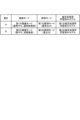
- step S2 If the magnitude of the movement determined in step S1 is less than a predetermined threshold (if the magnitude of the movement is small) (step S2: Yes), the imaging control unit 512 and the light source control unit 513 switch the imaging mode to the first imaging mode and switch the illumination mode to the first illumination mode (step S3).
- the magnitude of movement is determined during the removal operation.
- the image changes in posture significantly because the insertion must be performed while searching for a path that is gentle on the living body.
- the image changes in posture only slightly because the removal can be performed with a relatively simple operation, making observation and diagnosis relatively easy. Note that, regardless of the above, the magnitude of movement may be determined regardless of the direction of operation.
- the first imaging mode is a mode in which the imaging frame rate (FPS) of the imaging unit 27 is a normal imaging frame rate (normal FPS) such as 60 (FPS), and the resolution is a resolution that uses all pixels in the effective pixel area (normal resolution). That is, in step S3, the imaging control unit 512 controls the operation of the imaging unit 27 and switches the imaging mode to the first imaging mode.
- FPS imaging frame rate
- normal FPS normal imaging frame rate
- the resolution is a resolution that uses all pixels in the effective pixel area
- the first lighting mode is a mode in which the observation light output from the light source device 4 is normal, as shown in FIG. 4. That is, in step S3, the light source control unit 513 controls the operation of the light source device 4 to switch the lighting mode to the first lighting mode.
- the captured image acquisition unit 514 sequentially acquires captured images generated by the imaging unit 27 capturing the return light of the observation light from inside the subject PA while the observation light of normal output is irradiated from the light source device 4 into the subject PA (step S4). Since the captured images are in the first imaging mode, they are images of normal resolution captured at normal FPS. For ease of explanation, the captured images will be referred to as first captured images below.
- the image processing unit 515 executes image processing on the first captured images sequentially acquired in step S4 (step S5).
- the first captured image after image processing by the image processing unit 515 in step S5 is referred to as a first processed image.
- the image processing unit 515 outputs the first processed image to the image generating unit 516 and the estimation unit 517.
- Examples of the image processing include known image processing such as gain adjustment, white balance adjustment, gamma correction, edge emphasis correction, and enlargement/reduction adjustment.
- the image generating unit 516 After step S5, the image generating unit 516 generates an image suitable for display from the first processed image and outputs it (step S6).
- the image generating unit 516 estimates the image quality of the input first processed image using the trained model for high-definition processing, and if it is estimated that the first processed image has low image quality, it performs high-definition processing to generate a high-definition image with high image quality as if it was generated by an endoscope that generates high-image quality images (hereinafter referred to as a high-image-quality endoscope).
- a high-image-quality endoscope an endoscope that generates high-image quality images
- the high-definition image generated in step S6 will be referred to as the first high-definition image.
- the first high-definition image and the image with the image quality of the first processed image described above correspond to the image to be diagnosed according to the present invention.
- the high-definition processing corresponds to the generation processing of the image to be diagnosed according to the present invention.
- the first high-definition image is an image captured in normal FPS because it is captured in the first imaging mode.
- the trained model for high definition processing is stored in advance in the storage unit 54.
- the trained model for high definition processing is a trained model obtained by repeatedly executing a training process on the trained model using multiple sets of training images and teacher data, each set being a training image and teacher data.
- the training image is an image obtained by lowering the image quality of an image captured by a high image quality endoscope (hereinafter referred to as a high image quality image) to an image quality corresponding to the first processed image.
- the teacher data is the high image quality image.
- the trained model used in the training process is, for example, a CNN (Convolutional Neural Network).
- the trained model for high image quality processing includes a weight file (learning parameters) having weight values and bias values for each layer of the CNN.
- the neural network used in the learning process to generate a trained model for image quality improvement processing is not limited to CNN, and other neural networks may be used.
- various well-known learning algorithms can be used as the machine learning algorithm in the neural network.
- a supervised learning algorithm using the backpropagation method can be used.
- step S5 the estimation unit 517 performs an estimation process on the first processed image using the learned model for the first estimation process, thereby estimating diagnostic candidate areas that become diagnostic candidates for each specified area in the first processed image (step S7).
- FIG. 3 shows step S7 being executed after step S6, in reality steps S6 and S7 are executed in parallel substantially simultaneously.
- the first trained model for estimation processing corresponds to the trained model according to the present invention.
- This first trained model for estimation processing is stored in advance in the storage unit 54.
- the first trained model for estimation processing is a trained model obtained by repeatedly executing a training process on the trained model using multiple sets of training images and teacher data, each set being a training image and teacher data.
- the training images are images captured inside a living body.
- the teacher data are data annotated with the classification class, correct position, and size of lesions and the like in the training images.
- the training model used in the training process is, for example, a CNN.
- the trained model for estimation processing includes a weight file (learning parameters) having weight values and bias values for each layer of the CNN.
- the neural network used in the learning process to generate the trained model for the first estimation process is not limited to CNN, and other neural networks may be used.
- neural networks such as DNN (Deep Neural Network), Transformer, and GAN (Generative Adversarial Network) may be used as appropriate.
- various well-known learning algorithms may be used as the machine learning algorithm in the neural network. For example, a supervised learning algorithm using the backpropagation method may be used.
- the estimation unit 517 also performs an estimation process to output the reliability of the diagnostic candidate region for each specified region in the first processed image.
- the reliability of a diagnostic candidate region is a value indicating the level of reliability. Specifically, the reliability is a value that indicates the accuracy of image recognition in the diagnostic candidate region, and can also be considered as an index that indicates the probability that the object in the image is predicted to belong to a specific class. From the reliability of the diagnostic candidate region, it is possible to determine whether the object has been accurately recognized in the region.
- the estimation unit 517 estimates as a diagnostic candidate region an area whose reliability is equal to or exceeds the reliability threshold for a first number of consecutive frames out of the reliability for each predetermined region in the first processed image output by the estimation process. If there is an area whose reliability is momentarily equal to or exceeds the reliability threshold for only one frame in the time series, the estimated area may be a misdetected area and is therefore not treated as a diagnostic candidate region.
- FIG. 5 illustrates an example in which the first number of frames is "4". That is, even if the reliability of the region Ar in the first processed image F1(n) of the nth frame is equal to or greater than the reliability threshold, the estimation unit 517 does not yet estimate the region Ar as a diagnostic candidate region. Then, when the reliability of the region Ar is equal to or greater than the reliability threshold for four consecutive frames from the first processed image F1(n) of the nth frame to the first processed image F1(n+3) of the n+3th frame, the estimation unit 517 estimates the region Ar as a diagnostic candidate region.
- the input frame rate of the first processed images that are sequentially subjected to high definition processing in the image generation unit 516 and the input frame rate of the first processed images that are sequentially input to the estimation unit 517 are the same, at a normal FPS such as 60 (FPS).
- step S1 determines whether the magnitude of the movement determined in step S1 is equal to or greater than the predetermined threshold (if the magnitude of the movement is large) (step S2: No)
- step S2 determines whether the magnitude of the movement is large.
- the second imaging mode is a mode in which the imaging frame rate (FPS) of the imaging unit 27 is 120, 240, 480 (FPS) or the like (high FPS) which is higher than the normal FPS.
- the resolution is set to a resolution (low resolution) in which the number of pixels is lower than the normal resolution by thinning readout and pixel addition. That is, in step S8, the imaging control unit 512 controls the operation of the imaging unit 27 and switches the imaging mode to the second imaging mode.
- the second illumination mode is a mode in which the observation light from the light source device 4 is pulsed light with a higher output than the normal output. That is, in step S8, the light source control unit 513 controls the operation of the light source device 4 to switch the illumination mode to the second illumination mode.
- the image acquisition unit 514 sequentially acquires captured images generated by the imaging unit 27 capturing the return light of the observation light from inside the subject PA while the observation light, which is high-output pulsed light, is irradiated from the light source device 4 into the subject PA (step S9).
- the captured images are low-resolution images captured at a high FPS because they are in the second imaging mode.
- the captured images will be referred to as second captured images below.
- the image processing unit 515 sequentially performs image processing on the second captured images acquired in step S9, similar to step S5 (step S10).
- the second captured image after image processing by the image processing unit 515 in step S10 is referred to as a second processed image.
- the image processing unit 515 outputs the second processed image to the image generation unit 516 and the estimation unit 517, respectively.
- the image generating unit 516 thins out frames of the input second processed image to sequentially reduce the input frame rate at which high definition processing is performed, in order to obtain a frame rate that can be displayed on the display unit 52.
- the image generating unit 516 estimates the image quality of the input second processed image using a trained model for high definition processing, and if the second processed image is estimated to have low image quality, it performs high definition processing to generate a high definition image that is high image quality (high resolution) as if it was generated by a high image quality endoscope (step S11).
- the input second processed image is estimated to have high image quality, it outputs an image of the image quality of the second processed image without performing high definition processing.
- the image generating unit 516 since the image is a low resolution image in the second imaging mode, the image generating unit 516 often performs high definition processing on the second processed image.
- the execution of the high definition processing is determined according to the estimation result of whether the first and second processed images have high definition image quality, but this is not limited to the present configuration.
- the execution of the high definition processing may be switched according to the first imaging mode and the second imaging mode.
- the high definition image generated in step S11 will be referred to as the second high definition image.
- the second high definition image and the image of the image quality of the above-mentioned second processed image correspond to the image to be diagnosed according to the present invention.
- the second high definition image in this embodiment is in the second imaging mode, and the input frame rate is a normal FPS such as 60 (FPS) because the frames are thinned by the image generation unit 516.
- FPS normal FPS
- step S10 the estimation unit 517 performs an estimation process on the second processed image using the second learned model for estimation process, thereby estimating diagnostic candidate areas that become diagnostic candidates for each specified area in the second processed image (step S12).
- step S12 is executed after step S11, but in reality, steps S11 and S12 are executed in parallel substantially simultaneously.
- the second trained model for estimation processing corresponds to the trained model according to the present invention.
- This second trained model for estimation processing is pre-stored in the storage unit 54.
- the second trained model for estimation processing is a model in which the size of the feature map output by each layer is different from that of the first trained model for estimation processing. Therefore, the second trained model for estimation processing is a trained model generated using the same training images and teacher data as the first trained model for estimation processing, but is a model in which the layer structure and the number of channels in the network model of the neural network are different from those of the first trained model for estimation processing. That is, the estimation unit 517 switches the trained model for estimation processing depending on the magnitude of the movement determined in step S1 (FIG. 4).
- step S12 the estimation unit 517 estimates, as a diagnostic candidate region, a region in which the reliability is equal to or greater than the reliability threshold for a second number of consecutive frames that is smaller than the first number of frames, out of the reliability for each predetermined region in the second processed image output by the estimation process. That is, the estimation unit 517 switches the number of frames to the first number of frames or the second number of frames depending on the magnitude of the movement determined in step S1.
- the input frame rate of the second processed images that are successively subjected to high definition processing in the image generation unit 516 differs from the input frame rate of the second processed images that are successively input to the estimation unit 517.
- the input frame rate of the second processed images that are successively subjected to high definition processing in the image generation unit 516 is smaller than the input frame rate of the second processed images that are successively input to the estimation unit 517.
- the display control unit 518 After steps S6 and S7, or after steps S11 and S12, the display control unit 518 generates a display image to be displayed on the display unit 52 (step S13). Specifically, after steps S6 and S7, the display control unit 518 generates a display image based on the first high-definition image generated in step S6 and the diagnostic candidate region estimated in step S7. Also, after steps S11 and S12, the display control unit 518 generates a display image based on the second high-definition image generated in step S11 and the diagnostic candidate region estimated in step S12. Details of the display image will be described later in the section "Specific examples of display images.”
- FIG. 6 are diagrams showing specific examples of display images.
- the display control unit 518 generates a display image F1 shown in Fig. 6. Then, the display control unit 518 causes the display unit 52 to display the display image F1.
- the display image F1 includes an observation position image F11 and a diagnostic image F12.
- the observation position image F11 is an image in which the current observation position (tip position of the insertion section 21) OP is superimposed on an image showing the shape of the observation target (the large intestine in this embodiment).
- the position calculation unit 511 calculates the tip position OP of the insertion section 21 by a known method based on the magnetism emitted from the second sensor 29 and received by the receiving unit 55.
- the display control unit 518 then generates an observation position image F11 in which the tip position OP of the insertion section 21 (current observation position) calculated by the position calculation unit 511 is superimposed on an image showing the shape of the observation target, the position of which has been specified in advance.
- the diagnostic image F12 will have different forms depending on the magnitude of the movement determined in step S1.
- the diagnostic image F12 is the image shown in FIG. 7.
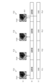
- FIG. 7(a) shows the diagnostic image F12 that is generated sequentially, with the horizontal axis representing time.
- FIG. 7(b) shows the frames of the first high-definition image that are generated sequentially, with the horizontal axis representing time.
- the frames are labeled "super-resolution.”
- the first processed image is often high-definition as described above, and the diagnostic image F12 has the image quality of the first processed image.
- FIG. 7(c) shows the frames of the first processed image that are subjected to estimation processing sequentially, with the horizontal axis representing time.
- the frames are labeled "CAD.”
- the input frame rate of the first processed images that are sequentially subjected to high definition processing in the image generation unit 516 and the input frame rate of the first processed images that are sequentially input to the estimation unit 517 are the same as a normal FPS, such as 60 (FPS).
- the display control unit 518 When the magnitude of the movement is small, the display control unit 518 generates a diagnostic image F12 in which the diagnostic candidate area Ar1 is superimposed on the first high-definition image F121 based on the first high-definition image F121 and the diagnostic candidate area Ar1 processed by the image generation unit 516 and the estimation unit 517 on the first processed image of the same frame (frame FL4 in the example of FIG. 7), as shown in FIG. 7.
- the display control unit 518 generates only the first high-definition image F121 as the diagnostic image F12 (frames FL1 to FL3 in the example of Figure 7).
- step S2 No
- the diagnostic image F12 becomes the image shown in FIG. 8.
- FIG. 8 shows the diagnostic image F12 which is generated sequentially, with the horizontal axis representing time.
- (b) of FIG. 8 shows the frames of the second high-definition image which are generated sequentially, with the horizontal axis representing time.
- the frames are labeled with the word "super-resolution.”
- (c) of FIG. 8 shows the frames of the second processed image which are subjected to estimation processing sequentially, with the horizontal axis representing time.
- the frames are labeled with the word "CAD.”
- the input frame rate of the second processed images that are sequentially subjected to high definition processing in the image generation unit 516 differs from the input frame rate of the second processed images that are sequentially input to the estimation unit 517.
- the input frame rate of the second processed images that are sequentially subjected to high definition processing in the image generation unit 516 is 60 (FPS).
- the input frame rate of the second processed images that are sequentially input to the estimation unit 517 is 240 (FPS).
- the display control unit 518 If the magnitude of the movement is large, the display control unit 518 generates a diagnostic image F12 shown below. As shown in Figure 8, the display control unit 518 generates a diagnostic image F12 in which a diagnostic candidate area Ar2 is superimposed on the second high-definition image F122 based on a second high-definition image F122 and a diagnostic candidate area Ar2 processed by the image generation unit 516 and the estimation unit 517 on a second processed image of the same frame (frame FL1 in the example of Figure 8).
- the display control unit 518 generates a diagnostic image F12 including the second high-definition image F122 and frame position information IF indicating the frame in which the diagnostic candidate area Ar2 was estimated (frame FL11 in the example of FIG. 8) based on the second high-definition image F122 and the diagnostic candidate area Ar2 processed by the image generation unit 516 and the estimation unit 517 on the second processed image of different frames (frames FL11 and FL13 in the example of FIG. 8), as shown in FIG. 8.
- the frame FL11 in which the diagnostic candidate area Ar2 was estimated is a frame captured at the back side of the second high-definition image F122 relative to frame FL13 of the second high-definition image F122, when the insertion unit 21 is removed.
- the diagnostic candidate region Ar2 may be superimposed as the diagnostic image F12 on a second high-definition image F122 of the frame FL13 that is closest to the frame FL11 in which the diagnostic candidate region Ar2 was estimated.
- the display control unit 518 generates only the second high-definition image F122 as the diagnostic image F12 (frames FL5 and FL9 in the example of Figure 8).
- the display control unit 518 then causes the display unit 52 to display the display image F2, for example.
- the control unit 51 stores in the storage unit 54 a diagnostic image F12 in which the diagnostic candidate regions Ar1 and Ar2 are superimposed on the first and second high-definition images F121 and F122.
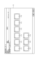
- the display control unit 518 in response to a user operation on the input unit 53, the display control unit 518 generates a display image F2 that displays a list of thumbnail images FT1 to FT9 of the multiple diagnostic images F12 stored in the storage unit .
- the control device 5 when the magnitude of the movement is large, the imaging mode is switched to the second imaging mode, and the illumination mode is switched to the second illumination mode. Therefore, the control device 5 can perform estimation processing on the second processed image without image blur caused by the high-speed movement of the insertion portion 21, and can accurately estimate the diagnostic candidate region.
- the control device 5 generates a second high-definition image in which the image quality (resolution) is increased by the high-definition processing on the second processed image that has been reduced in resolution by the second imaging mode. Therefore, the doctor or the like can confirm the appropriate diagnostic image F12. Therefore, according to the control device 5 of this embodiment, it is possible to quickly remove the insertion portion 21 in an observation area of low importance, thereby realizing diagnostic support that reduces the burden on the doctor.
- control device 5 switches the trained model for estimation processing depending on the magnitude of the movement determined in step S1. Therefore, by using an appropriate trained model for estimation processing according to the magnitude of movement, it is possible to appropriately estimate the diagnostic candidate area.
- control device 5 switches the number of frames used to estimate the diagnostic candidate region between the first number of frames or the second number of frames depending on the magnitude of the movement determined in step S1. This makes it possible to prevent erroneous estimation of a diagnostic candidate region.
- the image diagnosis support device according to the present invention is mounted on the endoscope system 1 in which the insertion section 21 is configured by a flexible endoscope, but the present invention is not limited to this.
- the image diagnosis support device according to the present invention may be mounted on an endoscope system in which the insertion section 21 is configured by a rigid endoscope.
- the image diagnosis support device may be mounted on a medical observation system such as a surgical microscope (see, for example, JP 2016-42981 A) that enlarges and observes a predetermined field of view area inside a subject (inside a living body) or on a subject's surface (surface of a living body).
- a medical observation system such as a surgical microscope (see, for example, JP 2016-42981 A) that enlarges and observes a predetermined field of view area inside a subject (inside a living body) or on a subject's surface (surface of a living body).
- the image generation unit 516 performs high-definition processing on the first and second processed images using a trained model for high-definition processing, thereby generating first and second high-definition images with improved image quality that appear as if they were generated by a high-image-quality endoscope that generates high-image-quality captured images, but the present invention is not limited to this.
- the image generating unit 516 may generate an image after filter processing such as edge enhancement or image enhancement, a contrast enhanced image, an image after filter processing such as structural color enhancement, an image after blur restoration (deconvolution image), or the like as the first and second high-definition images.
- the motion determination unit 510 determines the magnitude of relative motion between the insertion portion 21 and the subject based on a signal output from the first sensor 28 constituted by an acceleration sensor or an angular velocity sensor, but this is not limited to this.
- the movement determining section 510 may determine the magnitude of the relative movement between the insertion section 21 and the subject by a known method such as a block matching method or a gradient method based on the captured image.
- the diagnostic image F12 may include discrimination information that can distinguish when the insertion portion 21 is inserted into the body and when the insertion portion 21 is removed from the body. Furthermore, if a diagnostic candidate region is estimated at the time of insertion, the tip position of the insertion portion 21 at the time of estimation may be stored in the memory unit 54, and when the tip position of the insertion portion 21 approaches the tip position stored in the memory unit 54 at the time of removal, a notification unit such as the display unit 52 may be configured to notify the user of the approach.
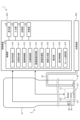
- Fig. 10 and Fig. 11 are diagrams for explaining the first modified example of the embodiment. Specifically, Fig. 10 is a diagram corresponding to Fig. 2. Fig. 11 is a block diagram showing the functions of the control unit 51. As shown in Figs. 10 and 11, in the control unit 51 according to the present modified example 1, a frame selection unit 519 is added to the control unit 51 explained in the above embodiment.
- the image generating unit 516 when the magnitude of the motion is large, the image generating unit 516 thins out frames of the input second processed image and sequentially reduces the input frame rate at which the high definition processing is executed. In other words, the image generating unit 516 itself performs the above-described thinning.
- the frame selection unit 519 performs the above-mentioned thinning out, rather than the image generation unit 516. That is, when the magnitude of the movement is large, the frame selection unit 519 performs the above-mentioned thinning out, and sequentially inputs the second processed images having the input frame rate reduced by the thinning out to the image generation unit 516.
- the frame selection unit 519 when the magnitude of the movement is small, the frame selection unit 519 does not perform the above-mentioned thinning out. That is, the first processed images are sequentially input to the image generation unit 516 while the frame rate is maintained.
- the image generating unit 516 also estimates the image quality of the image input from the frame selecting unit 519, and if it is estimated that the image quality is low, it performs high definition processing to generate and output a high definition image with high image quality, and if it is estimated that the image quality is high, it outputs an image of the input image quality without performing high definition processing.
- the high definition image and the image of the input image quality described above correspond to the image to be diagnosed according to the present invention.
- Fig. 12 is a diagram for explaining the second modified example of the embodiment. Specifically, Fig. 12 corresponds to Fig. 4 .
- the estimation unit 517 switches the trained model for estimation processing depending on the magnitude of the movement determined in step S1, but this is not limited to the above.
- the estimation unit 517 uses the same trained model for estimation processing both when the magnitude of the movement is small and when it is large.
- the estimation unit 517 uses a first threshold stored in the storage unit 54 as a reliability threshold used in the estimation processing.
- the estimation unit 517 uses a second threshold stored in the storage unit 54 as a reliability threshold used in the estimation processing.
- the first threshold and the second threshold are different thresholds.
- the control device 5 according to the present modified example 2 switches the reliability threshold used in the estimation process, that is, the detection sensitivity of the diagnostic candidate region, depending on the magnitude of the movement determined in step S1. Therefore, by using an appropriate reliability threshold according to the magnitude of the movement, it is possible to appropriately estimate the diagnosis candidate region.
Landscapes
- Health & Medical Sciences (AREA)
- Life Sciences & Earth Sciences (AREA)
- Surgery (AREA)
- Engineering & Computer Science (AREA)
- Medical Informatics (AREA)
- Biomedical Technology (AREA)
- Animal Behavior & Ethology (AREA)
- Radiology & Medical Imaging (AREA)
- Optics & Photonics (AREA)
- Nuclear Medicine, Radiotherapy & Molecular Imaging (AREA)
- Physics & Mathematics (AREA)
- Heart & Thoracic Surgery (AREA)
- Biophysics (AREA)
- Molecular Biology (AREA)
- Pathology (AREA)
- General Health & Medical Sciences (AREA)
- Public Health (AREA)
- Veterinary Medicine (AREA)
- Artificial Intelligence (AREA)
- Evolutionary Computation (AREA)
- Signal Processing (AREA)
- Endoscopes (AREA)
- Closed-Circuit Television Systems (AREA)
Abstract
Description
特許文献1に記載の技術では、内視鏡で撮像された撮像画像に対して学習済みモデルを用いて推定処理を実行することによって、当該撮像画像中の病変等の診断候補領域を推定している。
図1及び図2は、実施の形態に係る内視鏡システム1の構成を説明する図である。
内視鏡システム1は、本発明に係る画像診断支援システムに相当する。この内視鏡システム1は、医療分野において用いられ、ベッドBD(図1)上の患者である被検体PA(図1)の体内(本実施の形態では大腸)を観察するシステムである。この内視鏡システム1は、図1及び図2に示すように、内視鏡2と、処理装置3とを備える。
照明レンズ26は、挿入部21内において、ライトガイド25の一端に対向する。そして、照明レンズ26は、ライトガイド25によって伝達された観察光を被検体PAの体内に照射する。
次に、上述した制御装置5が実行する画像診断支援方法について説明する。
図3は、画像診断支援方法を示すフローチャートである。図4及び図5は、画像診断支援方法を説明する図である。
先ず、動き判定部510は、第1のセンサ28から出力された信号に基づいて、挿入部21と被写体との間の相対的な動きの大きさを判定する(ステップS1)。
当該画像処理としては、例えば、ゲイン調整、ホワイトバランス調整、ガンマ補正、輪郭強調補正、拡大縮小調整等の既知の画像処理を挙げることができる。
なお、図3では、ステップS6の後にステップS7が実行される形で記載しているが、実際には、ステップS6,S7は、略同時に並列に実行されるものである。
具体的には、信頼度は、診断候補領域における画像の認識の正確さを示す値であり、画像となる物体が、特定のクラスに属していると予測された確率を示す値を意味する指標ともいえる。診断候補領域の信頼度から、領域内で物体を正確に認識されているかを判定することができる。
なお、図3では、ステップS11の後にステップS12が実行される形で記載しているが、実際には、ステップS11,S12は、略同時に並列に実行されるものである。
具体的に、表示制御部518は、ステップS6,S7の後、当該ステップS6において生成された第1の高精細画像と、当該ステップS7において推定された診断候補領域とに基づいて、表示画像を生成する。また、表示制御部518は、ステップS11,S12の後、当該ステップS11において生成された第2の高精細画像と、当該ステップS12において推定された診断候補領域とに基づいて、表示画像を生成する。
なお、表示画像の詳細については、後述する「表示画像の具体例」において説明する。
次に、表示部52に表示される表示画像の具体例について説明する。
図6ないし図9は、表示画像の具体例を示す図である。
例えば、表示制御部518は、上述した画像診断支援方法において、図6に示す表示画像F1を生成する。そして、表示制御部518は、当該表示画像F1を表示部52に表示させる。
表示制御部518は、図8に示すように、画像生成部516及び推定部517によって同一フレーム(図8の例ではフレームFL1)の第2の処理済画像に対して処理された第2の高精細画像F122及び診断候補領域Ar2に基づいて、当該第2の高精細画像F122上に診断候補領域Ar2を重畳した診断画像F12を生成する。
ここで、制御部51は、第1,第2の高精細画像F121,F122上に診断候補領域Ar1,Ar2が重畳された診断画像F12を記憶部54に記憶する。
そして、表示制御部518は、入力部53へのユーザ操作に応じて、記憶部54に記憶された複数の診断画像F12のサムネイル画像FT1~FT9を一覧表示した表示画像F2を生成する。
本実施の形態に係る制御装置5では、動きの大きさが大である場合には、撮像モードを第2の撮像モードに切り替え、照明モードを第2の照明モードに切り替える。このため、制御装置5は、挿入部21の高速移動による画像ブレのない第2の処理済画像に対して推定処理を行うことができ、診断候補領域を精度良く推定することができる。また、制御装置5は、第2の撮像モードによって低解像度となった第2の処理済画像に対して高精細化処理によって高画質化(高解像度化)された第2の高精細画像を生成する。このため、医師等は、適切な診断画像F12を確認することができる。
したがって、本実施の形態に係る制御装置5によれば、重要度の低い観察領域エリアにおいて素早く挿入部21を抜去することができ、医師の負担を軽減する診断支援を実現することができる。
このため、動きの大きさに応じた適切な推定処理用学習済みモデルを用いることで、診断候補領域を適切に推定することができる。
このため、診断候補領域を誤って推定してしまうことを抑制することができる。
ここまで、本発明を実施するための形態を説明してきたが、本発明は上述した実施の形態によってのみ限定されるべきものではない。
上述した実施の形態では、挿入部21を軟性内視鏡によって構成した内視鏡システム1に本発明に係る画像診断支援装置を搭載していたが、これに限らない。例えば、挿入部21を硬性内視鏡によって構成した内視鏡システムに本発明に係る画像診断支援装置を搭載しても構わない。また、被写体内(生体内)や被写体表面(生体表面)の所定の視野領域を拡大して観察する手術用顕微鏡(例えば、特開2016-42981号公報参照)等の医療用観察システムに本発明に係る画像診断支援装置を搭載しても構わない。
例えば、画像生成部516は、エッジ強調や画像強調等のフィルタ処理後の画像、コントラスト強調画像、構造色彩強調のフィルタ処理後の画像、ボケ復元後の画像(デコンボリューション画像)等を第1,第2の高精細画像として生成しても構わない。
例えば、動き判定部510は、撮像画像に基づいて、ブロックマッチング法や勾配法等の公知の方法によって挿入部21と被写体との間の相対的な動きの大きさを判定しても構わない。
図10及び図11は、実施の形態の変形例1を説明する図である。具体的に、図10は、図2に対応した図である。図11は、制御部51の機能を示すブロック図である。
本変形例1に係る制御部51では、図10及び図11に示すように、上述した実施の形態において説明した制御部51に対して、フレーム選択部519が追加されている。
これに対して、本変形例1では、画像生成部516ではなくフレーム選択部519が上述した間引きを行う。すなわち、フレーム選択部519は、動きの大きさが大である場合には、上述した間引きを行い、当該間引きによって小さくなった入力フレームレートの第2の処理済画像を順次、画像生成部516に入力する。一方、フレーム選択部519は、動きの大きさが小である場合には、上述した間引きを行わない。すなわち、画像生成部516には、フレームレートが維持された状態で、順次、第1の処理済画像が入力される。
図12は、実施の形態の変形例2を説明する図である。具体的に、図12は、図4に対応した図である。
上述した実施の形態では、推定部517は、ステップS1において判定された動きの大きさに応じて、推定処理用学習済みモデルを切り替えていたが、これに限らない。
本変形例2では、推定部517は、動きの大きさが小である場合、大である場合の双方において、同一の推定処理用学習済みモデルを用いる。また、推定部517は、動きの大きさが小である場合には、推定処理で用いる信頼度閾値として、記憶部54に記憶された第1の閾値を用いる。一方、推定部517は、動きの大きさが大である場合には、推定処理で用いる信頼度閾値として、記憶部54に記憶された第2の閾値を用いる。当該第1の閾値と当該第2の閾値とは異なる閾値である。
本変形例2に係る制御装置5では、ステップS1において判定された動きの大きさに応じて、推定処理で用いる信頼度閾値を、つまりは診断候補領域の検出感度を切り替える。
このため、動きの大きさに応じた適切な信頼度閾値を用いることで、診断候補領域を適切に推定することができる。
2 内視鏡
3 処理装置
4 光源装置
5 制御装置
21 挿入部
22 操作部
23 ユニバーサルコード
24 コネクタ部
25 ライトガイド
26 照明レンズ
27 撮像部
28 第1のセンサ
29 第2のセンサ
51 制御部
52 表示部
53 入力部
54 記憶部
55 受信部
271 レンズユニット
272 撮像素子
510 動き判定部
511 位置算出部
512 撮像制御部
513 光源制御部
514 撮像画像取得部
515 画像処理部
516 画像生成部
517 推定部
518 表示制御部
519 フレーム選択部
Ar,Ar1,Ar2 診断候補領域
BD ベッド
F1,F2 表示画像
F11 観察位置画像
F12 診断画像
F121 第1の高精細画像
F122 第2の高精細画像
FT1~FT9 サムネイル画像
IF フレーム位置情報
OP 観察位置
PA 被検体
Claims (24)
- 被写体を撮像する撮像装置で撮像された撮像画像を取得する撮像画像取得部と、
前記撮像装置と前記被写体との間の相対的な動きの大きさを判定する動き判定部と、
前記撮像画像に対して画像処理を実行して処理済画像を出力する画像処理部と、
前記処理済画像に基づいて診断対象となる画像を生成する画像生成部と、
学習済みモデルを用いて前記処理済画像に対して推定処理を実行することによって、前記処理済画像中の診断候補となる診断候補領域を推定する推定部とを備え、
前記画像生成部において順次、前記診断対象となる画像の生成処理を実行する前記処理済画像の入力フレームレートと、前記推定部に順次、入力する前記処理済画像の入力フレームレートとは、
前記動きの大きさに応じて異なる画像診断支援装置。 - 前記画像生成部は、
学習済みモデルを用いて前記処理済画像の画質に応じて高精細化処理を実行することによって、前記診断対象となる画像を生成する請求項1に記載の画像診断支援装置。 - 前記画像生成部は、
前記処理済画像に対して高精細化処理を実行することによって前記処理済画像よりも高精細な高精細画像を前記診断対象となる画像として生成する請求項1に記載の画像診断支援装置。 - 前記診断対象となる画像と、前記診断候補領域とに基づいて、表示画像を生成する表示制御部をさらに備える請求項1に記載の画像診断支援装置。
- 前記画像生成部は、
前記処理済画像に対して高精細化処理を実行することによって前記処理済画像よりも高画質の高精細画像を前記診断対象となる画像として生成する請求項4に記載の画像診断支援装置。 - 前記動きの大きさに応じて、前記画像生成部において順次、前記診断対象となる画像の生成処理を実行する前記処理済画像の入力フレームレートと、前記推定部に順次、入力する前記処理済画像の入力フレームレートを異なるものとするフレーム選択部をさらに備える請求項1に記載の画像診断支援装置。
- 前記動きの大きさに応じて前記撮像装置の撮像モードを切り替える撮像制御部をさらに備える請求項1に記載の画像診断支援装置。
- 前記撮像制御部は、
前記動きの大きさに応じて前記撮像装置による撮像フレームレートを切り替える請求項7に記載の画像診断支援装置。 - 前記動きの大きさに応じて前記被写体に照明光を供給する光源装置の照明モードを切り替える光源制御部をさらに備える請求項1に記載の画像診断支援装置。
- 前記動きの大きさが所定の閾値以上である場合には、前記推定部に順次、入力する前記処理済画像の入力フレームレートは、前記画像生成部において順次、前記診断対象となる画像の生成処理を実行する前記処理済画像の入力フレームレートよりも大きい請求項1に記載の画像診断支援装置。
- 前記画像生成部は、
前記動きの大きさが所定の閾値以上である場合には、入力する前記処理済画像のフレームを間引き、前記画像生成部において前記診断対象となる画像の生成処理を実行する前記処理済画像の入力フレームレートを前記推定部に順次、入力する前記処理済画像の入力フレームレートよりも小さくする請求項10に記載の画像診断支援装置。 - 前記診断対象となる画像と、前記診断候補領域とに基づいて、表示画像を生成する表示制御部をさらに備え、
前記表示制御部は、
前記画像生成部及び前記推定部によって同一フレームの前記処理済画像に対して処理された前記診断対象となる画像及び前記診断候補領域に基づいて前記診断対象となる画像上に前記診断候補領域を重畳した前記表示画像を生成する請求項1に記載の画像診断支援装置。 - 前記診断対象となる画像と、前記診断候補領域とに基づいて、表示画像を生成する表示制御部をさらに備え、
前記表示制御部は、
前記画像生成部及び前記推定部によって異なるフレームの前記処理済画像に対して処理された前記診断対象となる画像及び前記診断候補領域に基づいて、前記診断対象となる画像と前記診断候補領域を推定したフレームを示す情報とを含む前記表示画像を生成する請求項1に記載の画像診断支援装置。 - 前記診断対象となる画像と、前記診断候補領域とに基づいて、表示画像を生成する表示制御部をさらに備え、
前記表示制御部は、
前記画像生成部及び前記推定部によって異なるフレームの前記処理済画像に対して処理された前記診断対象となる画像及び前記診断候補領域に基づいて、前記診断候補領域を推定したフレームの前記処理済画像に対して直近のフレームの前記処理済画像から生成された前記診断対象となる画像上に前記診断候補領域を重畳した前記表示画像を生成する請求項1に記載の画像診断支援装置。 - 前記動き判定部は、
前記撮像装置に設けられた加速度センサまたは角速度センサの少なくとも1つの出力に基づいて、前記動きの大きさを判定する請求項1に記載の画像診断支援装置。 - 前記動き判定部は、
前記処理済画像に基づいて、前記動きの大きさを判定する請求項1に記載の画像診断支援装置。 - 前記推定部は、
前記動きの大きさに応じて、前記学習済みモデルを切り替える請求項1に記載の画像診断支援装置。 - 前記推定部は、
前記推定処理によって出力する前記処理済画像における所定の領域毎の信頼度のうち、信頼度閾値以上となる信頼度の領域を前記診断候補領域として推定し、前記動きの大きさに応じて、前記信頼度閾値を切り替える請求項1に記載の画像診断支援装置。 - 前記推定部は、
前記推定処理によって出力する前記処理済画像における所定の領域毎の信頼度のうち、所定のフレーム数だけ連続して信頼度閾値以上となる信頼度の領域を前記診断候補領域として推定し、前記動きの大きさに応じて、前記所定のフレーム数を切り替える請求項1に記載の画像診断支援装置。 - 被写体を撮像する撮像装置で撮像された撮像画像を取得する撮像画像取得部と、
前記撮像装置と前記被写体との間の相対的な動きの大きさを判定する動き判定部と、
前記撮像画像に対して画像処理を実行して処理済画像を出力する画像処理部と、
前記処理済画像に対して高精細化処理を実行することによって前記処理済画像よりも高精細な高精細画像を生成する画像生成部と、
学習済みモデルを用いて前記処理済画像に対して推定処理を実行することによって、前記処理済画像中の診断候補となる診断候補領域を推定する推定部と、
前記高精細画像と、前記診断候補領域とに基づいて、表示画像を生成する表示制御部とを備え、
前記表示制御部は、
前記動きの大きさに応じて、前記表示画像の形態を切り替える画像診断支援装置。 - 前記動きの大きさが所定の閾値以上である場合には、前記推定部に順次、入力する前記処理済画像の入力フレームレートは、前記画像生成部において順次、前記高精細化処理を実行する前記処理済画像の入力フレームレートよりも大きい請求項20に記載の画像診断支援装置。
- 前記表示制御部は、
前記動きの大きさが前記所定の閾値未満である場合には、前記画像生成部及び前記推定部によって同一フレームの前記処理済画像に対して処理された前記高精細画像及び前記診断候補領域に基づいて前記高精細画像上に前記診断候補領域を重畳した前記表示画像を生成し、
前記動きの大きさが前記所定の閾値以上である場合には、前記画像生成部及び前記推定部によって同一フレームの前記処理済画像に対して処理された前記高精細画像及び前記診断候補領域に基づいて前記高精細画像上に前記診断候補領域を重畳した前記表示画像を生成するとともに、前記画像生成部及び前記推定部によって異なるフレームの前記処理済画像に対して処理された前記高精細画像及び前記診断候補領域に基づいて、前記高精細画像と前記診断候補領域を推定したフレームを示す情報とを含む前記表示画像を生成する請求項21に記載の画像診断支援装置。 - 被写体を撮像することによって撮像画像を生成する撮像装置と、
前記撮像画像を処理する画像診断支援装置とを備え、
前記画像診断支援装置は、
前記撮像画像を取得する撮像画像取得部と、
前記撮像装置と前記被写体との間の相対的な動きの大きさを判定する動き判定部と、
前記撮像画像に対して画像処理を実行して処理済画像を出力する画像処理部と、
前記処理済画像に対して高精細化処理を実行することによって前記処理済画像よりも高精細な高精細画像を生成する画像生成部と、
学習済みモデルを用いて前記処理済画像に対して推定処理を実行することによって、前記処理済画像中の診断候補となる診断候補領域を推定する推定部とを備え、
前記画像生成部において順次、前記高精細化処理を実行する前記処理済画像の入力フレームレートと、前記推定部に順次、入力する前記処理済画像の入力フレームレートとは、
前記動きの大きさに応じて異なる画像診断支援システム。 - 画像診断支援装置が実行する画像診断支援方法であって、
被写体を撮像する撮像装置で撮像された撮像画像を取得するステップと、
前記撮像装置と前記被写体との間の相対的な動きの大きさを判定するステップと、
前記撮像画像に対して画像処理を実行して処理済画像を出力するステップと、
前記処理済画像に対して高精細化処理を実行することによって前記処理済画像よりも高精細な高精細画像を生成するステップと、
学習済みモデルを用いて前記処理済画像に対して推定処理を実行することによって、前記処理済画像中の診断候補となる診断候補領域を推定するステップとを備え、
前記高精細化処理を実行する画像生成部において順次、前記高精細化処理を実行する前記処理済画像の入力フレームレートと、前記推定処理を実行する推定部に順次、入力する前記処理済画像の入力フレームレートとは、
前記動きの大きさに応じて異なる画像診断支援方法。
Priority Applications (4)
| Application Number | Priority Date | Filing Date | Title |
|---|---|---|---|
| PCT/JP2023/025097 WO2025009147A1 (ja) | 2023-07-06 | 2023-07-06 | 画像診断支援装置、画像診断支援システム、及び画像診断支援方法 |
| JP2025530927A JPWO2025009147A1 (ja) | 2023-07-06 | 2023-07-06 | |
| CN202380099373.6A CN121311160A (zh) | 2023-07-06 | 2023-07-06 | 图像诊断辅助装置、图像诊断辅助系统以及图像诊断辅助方法 |
| US19/421,368 US20260102052A1 (en) | 2023-07-06 | 2025-12-16 | Image diagnosis assistance apparatus, image diagnosis assistance system, and image diagnosis assistance method |
Applications Claiming Priority (1)
| Application Number | Priority Date | Filing Date | Title |
|---|---|---|---|
| PCT/JP2023/025097 WO2025009147A1 (ja) | 2023-07-06 | 2023-07-06 | 画像診断支援装置、画像診断支援システム、及び画像診断支援方法 |
Related Child Applications (1)
| Application Number | Title | Priority Date | Filing Date |
|---|---|---|---|
| US19/421,368 Continuation US20260102052A1 (en) | 2023-07-06 | 2025-12-16 | Image diagnosis assistance apparatus, image diagnosis assistance system, and image diagnosis assistance method |
Publications (1)
| Publication Number | Publication Date |
|---|---|
| WO2025009147A1 true WO2025009147A1 (ja) | 2025-01-09 |
Family
ID=94171811
Family Applications (1)
| Application Number | Title | Priority Date | Filing Date |
|---|---|---|---|
| PCT/JP2023/025097 Ceased WO2025009147A1 (ja) | 2023-07-06 | 2023-07-06 | 画像診断支援装置、画像診断支援システム、及び画像診断支援方法 |
Country Status (4)
| Country | Link |
|---|---|
| US (1) | US20260102052A1 (ja) |
| JP (1) | JPWO2025009147A1 (ja) |
| CN (1) | CN121311160A (ja) |
| WO (1) | WO2025009147A1 (ja) |
Citations (7)
| Publication number | Priority date | Publication date | Assignee | Title |
|---|---|---|---|---|
| WO2012176561A1 (ja) * | 2011-06-21 | 2012-12-27 | オリンパスメディカルシステムズ株式会社 | 医療機器 |
| JP2016042981A (ja) | 2014-08-21 | 2016-04-04 | ソニー・オリンパスメディカルソリューションズ株式会社 | 医療用観察装置および医療用観察システム |
| WO2019221306A1 (ja) * | 2018-05-18 | 2019-11-21 | オリンパス株式会社 | 内視鏡システム |
| WO2020003992A1 (ja) * | 2018-06-28 | 2020-01-02 | 富士フイルム株式会社 | 学習装置及び学習方法、並びに、医療画像処理装置 |
| WO2020230332A1 (ja) * | 2019-05-16 | 2020-11-19 | オリンパス株式会社 | 内視鏡、画像処理装置、内視鏡システム、画像処理方法およびプログラム |
| WO2021156974A1 (ja) * | 2020-02-05 | 2021-08-12 | オリンパス株式会社 | 画像処理装置、画像処理方法、画像処理プログラム、表示制御装置及び内視鏡装置 |
| WO2022004056A1 (ja) | 2020-07-03 | 2022-01-06 | 富士フイルム株式会社 | 内視鏡システム及びその作動方法 |
-
2023
- 2023-07-06 WO PCT/JP2023/025097 patent/WO2025009147A1/ja not_active Ceased
- 2023-07-06 JP JP2025530927A patent/JPWO2025009147A1/ja active Pending
- 2023-07-06 CN CN202380099373.6A patent/CN121311160A/zh active Pending
-
2025
- 2025-12-16 US US19/421,368 patent/US20260102052A1/en active Pending
Patent Citations (7)
| Publication number | Priority date | Publication date | Assignee | Title |
|---|---|---|---|---|
| WO2012176561A1 (ja) * | 2011-06-21 | 2012-12-27 | オリンパスメディカルシステムズ株式会社 | 医療機器 |
| JP2016042981A (ja) | 2014-08-21 | 2016-04-04 | ソニー・オリンパスメディカルソリューションズ株式会社 | 医療用観察装置および医療用観察システム |
| WO2019221306A1 (ja) * | 2018-05-18 | 2019-11-21 | オリンパス株式会社 | 内視鏡システム |
| WO2020003992A1 (ja) * | 2018-06-28 | 2020-01-02 | 富士フイルム株式会社 | 学習装置及び学習方法、並びに、医療画像処理装置 |
| WO2020230332A1 (ja) * | 2019-05-16 | 2020-11-19 | オリンパス株式会社 | 内視鏡、画像処理装置、内視鏡システム、画像処理方法およびプログラム |
| WO2021156974A1 (ja) * | 2020-02-05 | 2021-08-12 | オリンパス株式会社 | 画像処理装置、画像処理方法、画像処理プログラム、表示制御装置及び内視鏡装置 |
| WO2022004056A1 (ja) | 2020-07-03 | 2022-01-06 | 富士フイルム株式会社 | 内視鏡システム及びその作動方法 |
Also Published As
| Publication number | Publication date |
|---|---|
| JPWO2025009147A1 (ja) | 2025-01-09 |
| US20260102052A1 (en) | 2026-04-16 |
| CN121311160A (zh) | 2026-01-09 |
Similar Documents
| Publication | Publication Date | Title |
|---|---|---|
| US9154745B2 (en) | Endscope apparatus and program | |
| JP6478136B1 (ja) | 内視鏡システム、内視鏡システムの作動方法 | |
| US11025835B2 (en) | Imaging device, endoscope apparatus, and method for operating imaging device | |
| CN110099599B (zh) | 医学图像处理设备、医学图像处理方法和程序 | |
| JP6453905B2 (ja) | フォーカス制御装置、内視鏡装置及びフォーカス制御装置の制御方法 | |
| JP6996901B2 (ja) | 内視鏡システム | |
| US9826884B2 (en) | Image processing device for correcting captured image based on extracted irregularity information and enhancement level, information storage device, and image processing method | |
| JP6574448B2 (ja) | 内視鏡装置及び内視鏡装置のフォーカス制御方法 | |
| CN115066196B (zh) | 医用图像处理装置、内窥镜系统、医用图像处理方法及记录介质 | |
| JP7387859B2 (ja) | 医用画像処理装置、プロセッサ装置、内視鏡システム、医用画像処理装置の作動方法及びプログラム | |
| WO2018021035A1 (ja) | 画像処理装置および方法、内視鏡システム、並びにプログラム | |
| EP3886681B1 (en) | Medical imaging systems and methods | |
| US20220296082A1 (en) | Surgical information processing apparatus, surgical information processing method, and surgical information processing program | |
| JP2011024628A (ja) | 画像処理装置、画像処理プログラムおよび画像処理方法 | |
| US11523729B2 (en) | Surgical controlling device, control method, and surgical system | |
| JP2017213058A (ja) | 画像処理装置、内視鏡装置、画像処理方法、及び画像処理プログラム | |
| US20230414066A1 (en) | Endoscope image processing apparatus, endoscope image processing method, and endoscope image processing program | |
| JPWO2018225346A1 (ja) | 医療用システム及び制御ユニット | |
| WO2025009147A1 (ja) | 画像診断支援装置、画像診断支援システム、及び画像診断支援方法 | |
| CN114269221A (zh) | 医疗图像处理装置、内窥镜系统、医疗图像处理方法以及程序 | |
| WO2021149141A1 (ja) | フォーカス制御装置、内視鏡システム及びフォーカス制御装置の作動方法 | |
| JP2014003990A (ja) | 内視鏡装置および内視鏡観察システム | |
| WO2025009124A1 (ja) | 画像診断支援装置、画像診断支援システム、及び画像診断支援方法 | |
| JP6655433B2 (ja) | 電子内視鏡システム | |
| JPWO2020009127A1 (ja) | 医療用観察システム、医療用観察装置、及び医療用観察装置の駆動方法 |
Legal Events
| Date | Code | Title | Description |
|---|---|---|---|
| 121 | Ep: the epo has been informed by wipo that ep was designated in this application |
Ref document number: 23944395 Country of ref document: EP Kind code of ref document: A1 |
|
| ENP | Entry into the national phase |
Ref document number: 2025530927 Country of ref document: JP Kind code of ref document: A |
|
| WWE | Wipo information: entry into national phase |
Ref document number: 2025530927 Country of ref document: JP |
|
| WWE | Wipo information: entry into national phase |
Ref document number: 2023944395 Country of ref document: EP |
|
| NENP | Non-entry into the national phase |
Ref country code: DE |
|
| ENP | Entry into the national phase |
Ref document number: 2023944395 Country of ref document: EP Effective date: 20260206 |