WO2025009043A1 - 映像表示方法、映像情報作成装置、及び映像情報表示システム - Google Patents
映像表示方法、映像情報作成装置、及び映像情報表示システム Download PDFInfo
- Publication number
- WO2025009043A1 WO2025009043A1 PCT/JP2023/024700 JP2023024700W WO2025009043A1 WO 2025009043 A1 WO2025009043 A1 WO 2025009043A1 JP 2023024700 W JP2023024700 W JP 2023024700W WO 2025009043 A1 WO2025009043 A1 WO 2025009043A1
- Authority
- WO
- WIPO (PCT)
- Prior art keywords
- user
- display
- information
- area
- identification object
- Prior art date
- Legal status (The legal status is an assumption and is not a legal conclusion. Google has not performed a legal analysis and makes no representation as to the accuracy of the status listed.)
- Ceased
Links
Images

















Classifications
-
- G—PHYSICS
- G09—EDUCATION; CRYPTOGRAPHY; DISPLAY; ADVERTISING; SEALS
- G09G—ARRANGEMENTS OR CIRCUITS FOR CONTROL OF INDICATING DEVICES USING STATIC MEANS TO PRESENT VARIABLE INFORMATION
- G09G5/00—Control arrangements or circuits for visual indicators common to cathode-ray tube indicators and other visual indicators
Definitions
- This technology relates to a video display method, a video display device, and a video information display system, and in particular to a video information creation device, a video information display system, and an information terminal device that use AR (Augmented Reality) to provide guidance for finding a desired object.
- AR Augmented Reality
- Patent Document 1 discloses the following statement: "The information processing device includes a display method setting unit that sets a display method for visual information to be displayed superimposed on the field of view of multiple users, and a display control unit that controls the display of the visual information according to the set display method.
- the display method includes an individual display that displays the visual information for each user individually, and an integrated display that integrates and displays the visual information for multiple users. This technology can be applied, for example, to a vehicle that displays visual information using AR (summary excerpt)."
- Patent Document 1 is a technology for an in-vehicle HUD (head-up display) that uses a stereo camera to measure the distance to an object and focuses the image (visual information) at the same position as the object, making it difficult for the visual information and the object's position to shift even if the driver's viewpoint shifts sideways. Therefore, since a vehicle is driven by only one person, Patent Document 1 does not take into consideration the possibility of multiple users viewing from various positions.
- Patent Document 1 is applied to a situation where it is desired to simultaneously provide multiple users with guide information that allows them to see an object of interest, such as a tourist guide for an observation deck, etc., the multiple users will be searching for the object from different viewpoints, and so there remain issues such as the guidance not being appropriate for each user and directing their gaze in the wrong direction, or it becoming unclear which user the guidance is for when guidance is given to each user at the same time.
- the present invention has been made to solve the above problems, and aims to simultaneously guide multiple users in the direction of an object as seen by each of them.
- the present invention has the configuration described in the claims.
- FIG. 2 is a hardware configuration diagram of the video information creation device according to the first embodiment.
- 1 is a diagram showing a functional block configuration of a video information creation device according to a first embodiment
- FIG. 2 is a diagram illustrating a first example of visual information of the video information creation device according to the first embodiment.
- FIG. 2 is a diagram showing a main process flow of a first example of the video information creation device according to the first embodiment.
- FIG. 11 is a diagram showing a second example for explaining visual information of the video information creation device of the first embodiment.
- FIG. 11 is a diagram showing a main process flow of a second example of the video information creation device of the first embodiment.
- FIG. 2 is a diagram showing a first example of object creation by the video information creation device of the first embodiment.
- FIG. 11 is a diagram showing a second example of object creation by the video information creation device of the first embodiment.
- FIG. 11 is a diagram showing a third example of object creation by the video information creation device of the first embodiment.
- FIG. 11 is a diagram showing a third example for explaining visual information of the video information creation device of the first embodiment.
- FIG. 11 is a diagram showing a main process flow of a third example of the video information creation device according to the first embodiment.
- FIG. 13 is a diagram showing a fourth example A for explaining visual information of the video information creation device of the first embodiment.
- FIG. 13 is a diagram showing a fourth example B for explaining visual information of the video information creation device of the first embodiment.
- FIG. 13 is a diagram showing a fourth C example for explaining visual information of the video information creation device of the first embodiment.
- FIG. 13A to 13C are diagrams illustrating main process flows of fourth A example, fourth B example, and fourth C example of the video information creation device of the first embodiment.
- FIG. 13 is a diagram showing a fifth example for explaining visual information of the video information creation device of the first embodiment.
- FIG. 13 is a diagram showing a main process flow of a fifth example of the video information creation device according to the first embodiment.
- FIG. 13 is a diagram showing a sixth example for explaining visual information of the video information creation device of the first embodiment.
- FIG. 13 is a diagram showing a main process flow of a sixth example of the video information creation device according to the first embodiment.
- FIG. 11 is a diagram showing a functional block configuration of a video information display system according to a second embodiment.
- FIG. 13 is a diagram showing a first example for explaining visual information of the video information display system according to the second embodiment.
- FIG. FIG. 13 is a diagram showing a main process flow of a first example of a video information display system according to a second embodiment.
- FIG. 13 is a diagram showing a main process flow of a first example of a video information display system according to a second embodiment.
- FIG. 13 is a diagram showing a main process flow of a first example of a video information display system according to a second embodiment.
- FIG. 11 is a diagram showing a second example for explaining visual information of the video information display system according to the second embodiment.
- FIG. 11 is a diagram showing a main process flow of a second example of the video information display system according to the second embodiment.
- FIG. 11 is a diagram showing a main process flow of a second example of the video information display system according to the second embodiment.
- FIG. 13 is a diagram illustrating a functional block configuration of an information terminal device according to a third embodiment.
- FIG. 13 is a diagram showing a first example for explaining visual information of an information terminal device according to the third embodiment.
- FIG. 13 is a diagram showing a first example for explaining visual information of an information terminal device according to the third embodiment.
- FIG. 13 is a diagram illustrating a main processing flow of a first example of an information terminal device according to the third embodiment.
- FIG. 13 is a diagram illustrating a main processing flow of a first example of an information terminal device according to the third embodiment.
- FIG. 13 is a diagram illustrating a main processing flow of a first example of an information terminal device according to the third embodiment.
- FIG. 13 is a diagram illustrating a main transmission/reception process flow of a first example of an information terminal device according to the third embodiment.
- FIG. 13 is a diagram illustrating a main transmission/reception process flow of a first example of an information terminal device according to the third embodiment.
- FIG. 13 is a diagram showing a second example for explaining visual information of the information terminal device of the third embodiment.
- FIG. 13 is a diagram showing another example of the second example for explaining visual information of the information terminal device of the third embodiment.
- FIG. 13 is a diagram illustrating a main processing flow of a second example of the information terminal device of the third embodiment.
- FIG. 13 is a diagram showing a transmission/reception process flow between the information terminal device of the third embodiment and a second example of the server.
- FIG. 13 is a diagram showing a third example for explaining visual information of the information terminal device of the third embodiment.
- FIG. 13 is a diagram showing another example of the third example for explaining visual information of the information terminal device of the third embodiment.
- FIG. 13 is a diagram showing a fourth example for explaining visual information of the information terminal device of the third embodiment.
- the present invention is expected to contribute to the achievement of the United Nations' Sustainable Development Goal (SDGs) 8.2 (increase economic productivity through diversification, technological improvement and innovation, particularly in industries that add value to goods and services and labor-intensive industries) by improving technology to create more effective use of virtual reality displays in labor-intensive industries through displaying virtual reality objects and guiding multiple users in the same space to a specific object that they can simultaneously view.
- SDGs Sustainable Development Goal
- the video information creation device 100 simultaneously displays directions to specific objects that can be seen in large, medium, and small observation rooms, building windows, school windows, vehicle windows such as trains and tourist buses, HUDs, and aquariums for multiple users.
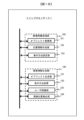
- FIG. 1A is a diagram showing the hardware configuration of a video information creation device according to a first embodiment of the present invention
- Fig. 1B is a diagram showing the functional block configuration of the video information creation device according to the first embodiment of the present invention.
- the video information creation device 100 in this embodiment is, for example, a see-through display, a head-up display, a smartphone, a tablet terminal, a personal computer, etc.
- the video information creation device 100 includes a main processor 101, a memory 110, an input/output interface 120, a display 134, a sensor group 150, a communication interface (I/F) 160, and an audio processing unit 170. These components are connected to each other via a bus 102.
- the memory 110 includes a RAM 111, a ROM 112, a flash memory 113, etc.
- the input/output interface 120 includes various button switches 121, a touch panel 122, etc.
- Display 134 is composed of a transparent display that allows you to see through to what is behind it (such as a transparent organic EL display, a transparent inorganic EL display, a transparent LCD display, or glass that can reflect and display projected information).
- a transparent display that allows you to see through to what is behind it (such as a transparent organic EL display, a transparent inorganic EL display, a transparent LCD display, or glass that can reflect and display projected information).
- the sensor group 150 includes a satellite positioning sensor 151, a geomagnetic sensor 152, a distance sensor 153, an in-camera 154, an out-camera 155, and other sensors 156.
- the communication interface 160 includes a wireless communication interface 161, a user information communication interface 162, a short-range wireless communication interface 163, etc.
- the audio processing unit 170 includes a speaker 171 as an audio output device and a microphone 172 as an audio input device.
- the memory 110 stores programs and the like for controlling the entire video information creation device 100 by the main processor 101. Various data and the like processed by each component are temporarily stored via the bus 102.
- the input/output interface 120 operates as follows.
- the various button switches 121 are, for example, switches that turn the operation of this function on or off.
- the touch panel 122 is composed of a means for inputting information by touching buttons and the like displayed on the display 134.
- the operation of the sensor group 150 is as follows.
- the satellite positioning sensor 151 is a sensor for measuring position using a satellite positioning system such as the Global Positioning System (GPS), and receives signals from multiple GPS satellites to obtain highly accurate three-dimensional current location information.
- GPS Global Positioning System
- RNSS Registered Public Information Satellite System
- SBAS Segmenting satellite group
- the geomagnetic sensor 152 detects the Earth's magnetic field and measures two-dimensional and three-dimensional directions.
- the distance sensor 153 measures distance by emitting ultrasonic waves or pulses of laser light, hitting the target and measuring the time it takes for the light to return.
- the in-camera 154 is an image capture device that captures the user looking at the display 134.
- the rear camera 155 is an image capture device that captures what is in front of the display 134 as seen by the user.
- Other sensors 156 are detectors for obtaining necessary information about the surrounding environment (brightness, temperature, noise, etc.) etc.
- the operation of the communication interface 160 is as follows.
- the wireless communication interface 161 is an interface that has the function of transmitting and receiving wireless communication used in mobile communications such as 4G/5G.
- the wireless communication interface 161 can obtain necessary information from a server on an external network.
- the user information communication interface 162 is an interface that has the function of transmitting and receiving medium-range wireless communication such as Wi-Fi (registered trademark).
- the short-range wireless communication interface 163 is an interface that has the function of transmitting and receiving short-range wireless communication such as Bluetooth (registered trademark) and NFC (Near Field Communication).
- the video information creation device 100 includes a video information processing unit 180 and a visual information generating unit 190 as its main functional blocks.
- the video information processing unit 180 includes an object superimposition unit 181, a position information creation unit 182, and a display method setting unit 183.
- the visual information generation unit 190 includes an object generation unit 191, a display method change unit 192, a user recognition unit 193, and a gaze position detection unit 194.
- the operation of the video information processing unit 180 is as follows.
- the position information creation unit 182 performs calculations to determine where on the display 134 the objects for each user created by the object generation unit 191 or the display method change unit 192 should be placed.
- the display method setting unit 183 sets the display method for the video information.
- the object superimposition unit 181 superimposes and displays the object for each user created by the object generation unit 191 or the display method change unit 192 at the placement position determined by the position information creation unit 182.
- the operation of the visual information generation unit 190 is as follows.
- the user recognition unit 193 detects and recognizes the user using the in-camera 154, etc.
- the object generation unit 191 creates objects that enable identification of each user recognized by the user recognition unit 193.
- the gaze position detection unit 194 detects which part of the display 134 is visible for each user.
- the display method change unit 192 appropriately changes the display method when the identification objects for each user cannot be displayed properly due to overlapping with each other, etc.
- the components included in the video information processing unit 180 and visual information generating unit 190 are configured by the main processor 101 executing the video display program according to this embodiment stored in the memory 110, and the hardware and the program work together to realize the functions of each component.
- the first example is characterized in that the specific object, which is an object that guides the user in the viewing direction, is a stationary object.
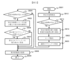
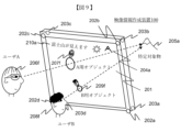
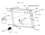
- Fig. 2 is a diagram showing a first example for explaining visual information of the video information creation device of the first embodiment.
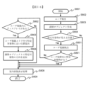
- Fig. 3 is a diagram showing a main processing flow of the first example of the video information creation device of the first embodiment.
- the video information creation device 100 includes a transparent display 201 as the display 134 for viewing the scenery from within the observation room, four sensor cameras 202a, 202b, 202c, and 202d as the in-cameras 154 arranged inside the four corners of the transparent display 201, and four sensor cameras 203a, 203b, 203c, and 203d as the out-cameras 155 arranged outside the four corners of the transparent display 201.
- the number and positions of the cameras arranged as the in-cameras 154 and out-cameras 155 are merely examples, and the number and positions of the cameras may be different from those in FIG. 2 as long as the desired image can be captured. This also applies to the other drawings.
- Mount Fuji, the sunset, etc. are displayed as at least one or more objects 204a that are points of interest from within the observation room.
- the object selected to guide the user in the direction to view is the specific object.
- the specific objects are selected one by one at a predetermined time interval from among the at least one object 204a.
- FIG. 2 it is assumed that specific object 205a (Mount Fuji) has been selected.
- the selection process for the specific object may be performed by the object generation unit 191, or the user may ordinarily speak the name of the specific object about which the user wishes to be guided, and the microphone 172 may collect the sound, and the object generation unit 191 may perform voice analysis to select the specific object.
- the object superimposition unit 181 displays guidance information with an identification object 207a for A added to the area on the transparent display 201 that is in the line of sight of the user A 206a looking at the specific object 205a (Mt. Fuji).
- the object superimposition unit 181 finds the area where a virtual line connecting the user's position and the position of the specific object intersects with the display, and uses this area as the area for displaying the identification object 207a for A.
- the guidance information is a figure that includes part or all of the specific object, and by adding an identification object, it is possible to know which user the guidance information is for.
- the object superimposition unit 181 displays guidance information with an identification object 209a for B added in the area on the transparent display 201 in the line of sight of user B 208a looking at the specific object 205a (Mt. Fuji). At this time, the object superimposition unit 181 displays text information 210 such as "Mt. Fuji is visible" in the upper left corner of the transparent display 201.
- the object 204a and text information 210 are stored in advance in the memory 110 according to the installation location of the video information creation device 100.
- the user recognition unit 193 recognizes a user (user A 206a or user B 208a) who is looking at the outdoor view through the transparent display 201 based on the image data obtained from the four sensor cameras 202a, 202b, 202c, and 202d arranged inside the four corners of the transparent display 201 (S802).
- the position information creation unit 182 determines the three-dimensional arrangement information of the specific object 205a (Mt. Fuji) and the transparent display 201 that it has previously determined, and the newly obtained three-dimensional position information of user A 206a and user B 208a. More precisely, the position information creation unit 182 detects the position information of the eyes of each user as the position information of user A 206a and user B 208a.
- the object generation unit 191 creates a different identification object for A 207a and an identification object for B 209a so that the detected user A 206a and user B 208a can be individually identified (S803).
- the position information creation unit 182 judges whether or not the user A 206a and the user B 208a are in a position where the specific object 205a (Mt. Fuji) can be seen through the transparent display 201 (S804). If it is judged in step 804 that the user A 206a and the user B 208a are not in a position where the specific object 205a (Mt. Fuji) can be seen (S804: No), the identification object 207a for A and the identification object 209a for B are not output, and the process proceeds directly to step 808, where other guidance information display processing is performed, and the process ends in step 809.
- the position information creation unit 182 determines that the user A 206a and the user B 208a are in a position where the specific object 205a (Mt. Fuji) is visible (S804: Yes)
- the position where the identification object 207a for A and the identification object 209a for B are displayed on the transparent display 201 connecting the specific object 205a (Mt. Fuji) and the user A 206a and the user B 208a is calculated in step 805 (S805). Note that if the distance between the specific object and the transparent display is sufficiently farther than the distance between the transparent display and the user and the distance between the users, the directions in which the users are viewing the specific object are considered to be almost the same.
- the object display position for each user may be calculated by calculating a three-dimensional direction vector to the specific object relative to the transparent display in advance, and translating the direction vector according to the user's position to simply calculate the position of the identification object, thereby reducing the amount of calculation processing. This is also true for other embodiments.
- the position information creation unit 182 judges whether the multiple identified objects for each user are adjacent or overlapping on the transparent display 201 (S806). For the multiple identified objects for which it is judged that the multiple identified objects for each user are adjacent or overlapping (S806: Yes), the display method change unit 192 changes them to an integrated object (described later) and outputs the changed object (S807), and the object superimposition unit 181 displays the integrated object on the transparent display 201 (S808), providing guidance to the position where the specific object 205a (Mt. Fuji) can be seen. The process then ends in step 809.
- the object generation unit 191 outputs the identified object 207a for A and the identified object 209a for B, and the object superimposition unit 181 displays guidance information with the identified objects (the identified object 207a for A and the identified object 209a for B) added on the transparent display 201 (S808), providing guidance to the position where the specific object 205a (Mt. Fuji) can be seen.
- the process then ends in step 809.
- the process in FIG. 3 is repeated in a cycle (e.g., 60, 120, 240 frames per second) in which one image is detected or displayed on the sensor cameras 202a, 202b, 202c, 202d or the transparent display 201.
- a cycle e.g., 60, 120, 240 frames per second
- the main processor 101 may output the text information 210 as audio guidance information from the speaker 171.
- the second example is characterized in that the specific object is a moving object.
- the sunset is taken as an example of the specific object.
- the position of the sunset relative to the user changes from moment to moment.
- FIG. 4 is a diagram showing a second example for explaining visual information of the video information creation device of the first embodiment.
- FIG. 5 is a diagram showing a main processing flow of the second example of the video information creation device of the first embodiment.
- the second example shows an example in which the specific object 205e (sunset) moves from moment to moment compared to the first example.
- the same reference numerals are used for the same or similarly functional parts as those in FIG. 2, and their explanation will be omitted.
- the video information creation device 100 is equipped with a transparent display 201 and sensor cameras 202a-d and 203a-d.
- a sunset is displayed as an example of an object 204e that can be seen from inside the observation room, and guidance information for a specific object 205e (sunset) is displayed.
- the object superimposition unit 181 displays an identification object 207e for A in an area on the transparent display 201 that is in the line of sight of user A 206e when he sees the specific object 205e (sunset). Similarly, the object superimposition unit 181 displays an identification object 209e for B in an area on the transparent display 201 that is in the line of sight of user B 208e when he sees the specific object 205e (sunset). At this time, text information 210e such as "You can see the sunset" is displayed in the upper left corner of the transparent display 201.
- FIG. 5 steps that perform the same processes or functions as those in FIG. 3 are given the same reference numerals, and their description will be omitted.
- the position information creation unit 182 detects a specific object 205e (sunset) based on the image data obtained from the four sensor cameras 203a, 203b, 203c, and 203d arranged on the outside of the four corners of the transparent display 201 (S812).
- the object generation unit 191 does not output the identified object, but proceeds directly to step 808 to perform other guidance information display processing, and ends at step 809.
- the position information creation unit 182 determines that the specific object 205e (sunset) has been detected (S813: Yes)
- the position information creation unit 182 calculates the position of the specific object 205e (sunset) from the output of the sensor cameras 203a, 203b, 203c, and 203d (S814).
- the position information creation unit 182 calculates the position information of the image information creation device 100 in the world coordinate system using the satellite positioning sensor 151 or the like, and communicates with a server on an external network via the wireless communication interface 161, and if the time at the location of the image information creation device 100 is known, the position information of the celestial body can be obtained.
- the sensor cameras 203a-d are also provided with the functionality of the distance sensor 153. If the specific object is a closer object such as an airplane, a bird, or a fish in an aquarium, the position information creation unit 182 may successively calculate the movement of the specific object by triangulation using the outputs of at least two or more of the sensor cameras 203a-d. From here on, steps 802-S809 are the same as those in FIG. 3.
- the process in FIG. 5 is repeated in a cycle (e.g., 60, 120, 240 frames per second) in which one image is detected or displayed on the sensor cameras 202a-d, 203a-d, or the transparent display 201.
- a cycle e.g., 60, 120, 240 frames per second
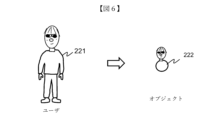
- FIG. 6 is a diagram showing the object generation unit 191 of the video information creation device of the first embodiment and a first example of the creation of an identification object in step 803.
- Fig. 7 is a diagram showing a second example of the creation of an object in the video information creation device of the first embodiment.
- Fig. 8 is a diagram showing a third example of the creation of an object in the video information creation device of the first embodiment.
- FIG. 6 shows a user 221 and an identification object 222 generated by the object generation unit 191 in step 803.
- the object generation unit 191 captures the external characteristics of the user 221 with the in-camera 154 as identification information for the user 221, and generates and displays an identification object 222 that highlights and identifies the face or characteristic parts of the entire body of the user 221 (face shape, hairstyle, eyebrows, eyes, nose, mouth, glasses, hat, body shape, clothing).
- the object generation unit 191 particularly extracts facial features, and creates an identification object 222 that represents a round body part and guides the user to see specific objects 205a, 205e within this circle.
- FIG. 7 shows an example of an integrated identification object.
- identification object 223 and identification object 224 for two users are adjacent or overlapping, parts of each identification object are integrated to form integrated object 225.
- the display method change unit 192 creates an integrated object 225 that uses the round body part in common in step 807. This makes it easier to see than displaying two identification objects overlapping each other.
- Figure 8 shows another example of an integrated object, integrated object 230, which integrates identification objects 226, 227, 228, and 229 of four users.
- the third example is an improved technology for making it easier to distinguish between identified objects of users close to the display 134 and those far from it.
- Fig. 9 is a diagram showing a third example for explaining visual information of the video information creation device of the first embodiment.
- Fig. 10 is a diagram showing a main processing flow of the third example of the video information creation device of the first embodiment.
- the same reference numerals are used for the same or similarly functional parts as those in Figs. 2 and 4, and their explanation will be omitted.
- the video information creation device 100 is equipped with a transparent display 201 and sensor cameras 202a-d and 203a-d.
- Mount Fuji is selected as the object 204a to be viewed from the observation deck, and guide information for the specific object 205a (Mount Fuji) is displayed.
- the object superimposition unit 181 displays an identification object 207f for A in an area on the transparent display 201 that is in the line of sight of user A 206f when looking at the specific object 205a (Mt. Fuji). Similarly, the object superimposition unit 181 displays an identification object 209e for B in an area on the transparent display 201 that is in the line of sight of user B 208f when looking at the specific object 205a (Mt. Fuji). At this time, text information 210a such as "Mt. Fuji is visible" is displayed in the upper left corner of the transparent display 201.
- the display mode of an identified object is different between an identified object of a user closer to the video information creation device 100 and an identified object of a user farther from the video information creation device 100.
- the display mode at least one of the size, resolution, brightness, and saturation of a part or all of the identified object may be changed. This improves the ease with which each user can find their own identified object.
- FIG. 10 steps that perform the same processes or functions as those in FIG. 3 and FIG. 5 are given the same reference numerals, and their description will be omitted.
- the display method change unit 192 executes the processing.
- the display method change unit 192 calculates the distance from the transparent display 201 for each detected user (user A 206f and user B 208f).
- the calculation method is triangulation using the outputs of at least two or more of the four sensor cameras 202a-d arranged inside the four corners of the transparent display 201.
- the sensor cameras 202a-d may also be provided with the function of the distance sensor 153 to calculate the distance.
- the display method change unit 192 changes at least one of the size, resolution, brightness, and saturation of the identified object created in step 803 for each user (user A 206f and user B 208f) in part or all of the identified object according to the distance calculated in step 831.
- the identified object 209f for B which is closer, is displayed with the size of the round circle of the whole body reduced relative to the identified object 209f for B without changing the size of the facial features.
- user B 208f who approaches the transparent display 201 can display guidance information by narrowing down the range of positions where the specific object 205a can be seen more accurately.
- the positional relationship with other user A 206f makes it easier to distinguish between the user's own identification object 209f for B and the other user's identification object 207f for A, making it easier to find the user's own object on the transparent display 201.
- the same effect can be obtained by changing the resolution, brightness, saturation, etc. according to the distance.
- Examples 4A, 4B, and 4C are examples in which, when the identified objects of a user close to the display 134 and a user far from the display 134 overlap, the identified object of the closer user is preferentially displayed. Also shown is an example in which the visual information generating unit 190 and the video information processing unit 180 perform a method of displaying the identified object of the farther user so as not to obstruct the identified object of the closer user.
- FIGS. 11A, 11B, and 11C are diagrams showing examples 4A, 4B, and 4C for explaining the visual information of the video information creating device of the first embodiment.
- FIGS. 11A, 11B, and 11C are diagram showing the main processing flow of examples 4A, 4B, and 4C of the video information creating device of the first embodiment.
- FIGS. 11A, 11B, and 11C the same reference numerals are used for the same or similarly functional objects as those in FIGS. 2, 4, and 9, and their explanations are omitted.
- the video information creation device 100 is equipped with a transparent display 201 and sensor cameras 202a-d and 203a-d.
- Mount Fuji is selected as the object 204a to be viewed from inside the observation room, and guide information for the specific object 205a (Mount Fuji) is displayed.
- the fourth example A of the video information creation device shown in FIG. 11A is an example in which when the identification objects of a user close to the display 134 and a user far away overlap, the identification object of the closer user is preferentially displayed.
- the display of the identification object 207g (not shown) for A and the identification object 209g for B are adjacent to or overlapping in an area on the transparent display 201 in the line of sight of the user A 206g and the user B 208g looking at the specific object 205a (Mt.
- the object superimposition unit 181 preferentially displays the identification object 209g for B of the user B 208g who is closer to the display 134, and does not display part or all of the identification object 207g (not shown) for A of the user A 206g who is farther from the display 134, improving visibility on the transparent display 201.
- the display method change unit 192 preferentially displays the identification object 209g for B of the closer user B 208g when the display of the identification object 207g for A (not shown) and the identification object 209g for B overlap for each user (user A 206g and user B 208g) in step 806, and does not output part or all of the identification object 207g for A (not shown) of the farther user A 206g.
- the A-use identification object 207g of the distant user A 206g may be larger in size than the B-use identification object 209g of the close user B 208g.
- the A-use identification object 207g is displayed protruding from behind the B-use identification object 209g displayed preferentially, and the distant user A 206g also simultaneously displays the guidance information in step 808.
- the fourth example B of the video information creation device shown in FIG. 11B is one example of displaying an identification object 207g1 for A of a distant user A 206g.
- the identification object of a distant user is displayed outside the area that preferentially displays closer users.
- the user recognition unit 193 detects and recognizes each user (user A 206g and user B 208g), and the position information creation unit 182 calculates and determines the location of each user. Then, in step 841, the display method change unit 192, based on the above user identification results and the calculation results of the user locations, prevents the display of the A identification object 207g1 that overlaps with the area of the transparent display 201 that is hidden by the closer user B 208g as seen from the farther user A 206g (dashed line area in FIG. 11B).
- the fourth example C of the video information creation device shown in FIG. 11C is one of different display examples of the identification object 207g2 for A of a distant user A 206g.
- the fourth example C is outside the area in which a closer user is preferentially displayed, and the identification object of the distant user is more actively enlarged and displayed so that it is easy to see from a distance.
- the display method change unit 192 changes the size of the identification object for A of the distant user A to be actively larger than the identification object for B of the close user B.
- the identification object 207g2 for A of user A 206g is displayed larger so as not to interfere with user B 208g's view of the identification object 209g for B (and the specific object 205a visible beyond it) (as shown in FIG. 11C).
- the display of an identified object of a user who is farther away on the display does not obscure the identified object and specific object of a user who is closer to the display, making it easier for the closer user to see the specific object.
- the farther away user can display an identified object of a larger size that is easy to see even from a distance.
- the fifth example is an example in which a method of identifying users who are viewing the display 134 and users who are not viewing the display 134 and displaying identified objects only for users who are viewing the display 134 is performed by the gaze position detection unit 194 and the display method change unit 192.
- Fig. 13 is a diagram showing a fifth example for explaining visual information of the video information creation device of the first embodiment.
- Fig. 14 is a diagram showing a main processing flow of the fifth example of the video information creation device of the first embodiment.
- the same reference numerals are used for the same or similarly functional parts as those in Figs. 2, 4, 9, 11A, 11B, and 11C, and their explanations are omitted.
- the video information creation device 100 is equipped with a transparent display 201 and sensor cameras 202a-d and 203a-d.
- Mount Fuji is selected as the object 204a to be viewed from inside the observation room, and guide information for the specific object 205a (Mount Fuji) is displayed.
- an identification object 207h (not shown) for A and an identification object 209h for B are displayed in an area on the transparent display 201 that is in the line of sight of user A 206h and user B 208h looking at a specific object 205a (Mt. Fuji), if user A 206h is not looking in the direction of the transparent display 201, the identification object 207h (not shown) for A is not displayed, improving visibility on the transparent display 201.
- the gaze position detection unit 194 detects the eyes of each user from the user's face images obtained by the four sensor cameras 202a-d arranged inside the four corners of the transparent display 201, detects the gaze of each user, and generates gaze information.
- the gaze position detection unit 194 detects the gaze based on the position of the iris, with the inner corner of the eye or the like as a reference point (for example, if the iris of the left eye is far from the inner corner of the eye, the user is looking to the left, and if the inner corner of the left eye and the iris are close, the user is looking to the right).
- the field of view is set to approximately 60 degrees, for example, with the center of the gaze as the reference point.
- step 852 the gaze position detection unit 194 determines that a specific object 205a (Mt. Fuji) is present within the user's field of view via the transparent display 201 based on the user's gaze information (S852: Yes), the process proceeds to step 805 and the required identification object 209h for B is displayed.
- a specific object 205a Mt. Fuji
- the process proceeds to step 808 and guidance information based on the identified object is not displayed.
- the number of identification objects displayed on the display 134 can be reduced, and the viewing experience of users who are looking at the display 134 can be prevented from being hindered.
- the sixth example is an example of a method of displaying guidance information when a user who is not looking in the direction of the transparent display 201 in the fifth example starts to turn toward the transparent display 201.
- Fig. 15 is a diagram showing a sixth example for explaining visual information of the video information creation device of the first embodiment.
- Fig. 16 is a diagram showing a main processing flow of the sixth example of the video information creation device of the first embodiment.
- the same reference numerals are used for the same or similarly functional parts as those in Figs. 2, 4, 9, 11A, 11B, 11C, and 13, and description thereof will be omitted.
- the video information creation device 100 is equipped with a transparent display 201, and sensor cameras 202a-d and 203a-d.
- the sunset and Mt. Fuji which are the highlights from inside the observation room, are displayed as objects 204a, and guide information for a specific object 205a (Mt. Fuji) is displayed.
- identification object 207t1 (207t2, 207t3) for A
- a part of the identification object is displayed with information (an arrow mark in this embodiment) indicating the direction in which the specific object 205a (Mt. Fuji) can be seen. This makes it possible to guide the user's line of sight toward the specific object 205a when the user is looking in a direction different from the position where the specific object 205a is located.
- step 861, S862, and S863 the gaze position detection unit 194 is processed by the detection sensor 157, and step 864 is processed by the display method change unit 192 in FIG. 1.
- the process proceeds to step 808, where the object superimposition unit 181 displays the required identification object 209i for B (although not shown, steps 805 to S807 in FIG. 16 may be provided).
- the gaze position detection unit 194 determines whether or not a part of the transparent display 201 is within the user's line of sight (S862).
- the gaze position detection unit 194 determines that the user is in a position where the entire transparent display 201 is not visible within the user's gaze (S862: No), the identification object 207i for A is not displayed, and the process proceeds to step 808, where the object superimposition unit 181 displays other guidance information.
- the gaze position detection unit 194 determines that the user is in a position where a part of the transparent display 201 is visible within the user's gaze (S862: Yes)
- the object superimposition unit 181 displays guidance information by adding information indicating the direction in which the specific object 205a (Mt. Fuji) is visible to a part of the identified object as shown in the identified object 207t1 for A (S864).
- the displayed identification objects 207t1-207t3 for A and the identification object 207i for A are highlighted using video effects such as blinking, zooming out, fading in, etc. for a predetermined period of time. This process is performed by, for example, the display method change unit 192.
- the second embodiment relates to a video information display system in which the video information creation device 300 (100) of the first embodiment is combined with an information terminal device 400, and is an embodiment in which guidance information generated and displayed by the video information creation device is transmitted to an information terminal device carried by a user.
- Fig. 17 is a diagram showing the functional block configuration of the video information display system of the second embodiment.
- the video information creation device 300 of this second embodiment is, for example, a see-through display, a head-up display, a smartphone, a tablet terminal, a personal computer, etc., as described in Figures 1 to 16.
- the information terminal device 400 is, for example, a portable smartphone, a tablet terminal, a personal computer, a head-up display, etc.
- the video information creation device 300 in this embodiment includes a main processor 301, memory 310, an input/output interface 320, a sensor group 350, a communication interface 360, an audio processing unit 370, etc. These components are connected to each other via a bus 302. The details of each part are as explained in Figures 1 to 16 of the first embodiment.
- the video information processing unit 380 and the visual information generating unit 390 are configured by the main processor 301 executing the video display processing program according to this embodiment.
- the video information processing unit 380 and the visual information generating unit 390 which are functional blocks configured by cooperation between hardware and software, are also illustrated in FIG. 17 in the same manner as the hardware elements that configure the video information creation device 300, but the video information processing unit 380 and the visual information generating unit 390 are the same elements as the video information processing unit 180 and the visual information generating unit 190 described in FIG. 1B.
- the information terminal device 400 includes a main processor 401, a memory 410, an input/output interface 420, a display 434, a video information processing unit 480, a group of sensors 450, a communication interface 460, and an audio processing unit 470. These components are connected to each other via a bus 402.
- the memory 410 includes a RAM 411, a ROM 412, a flash memory 413, etc.
- the input/output interface 420 includes various button switches 421, a touch panel 422, etc.
- the video information processing unit 480 includes an object superimposition unit 481, a position information creation unit 482, and a display method setting unit 483.
- the sensor group 450 includes a satellite positioning sensor 451, a geomagnetic sensor 452, a distance sensor 453, an in-camera 454, an out-camera 455, other sensors 456, an acceleration sensor 457, a gyro sensor 458, a biometric information acquisition sensor 459, etc.
- the communication interface 460 includes a wireless communication interface 461, a user information communication interface 462, and a short-range wireless communication interface 463.
- the audio processing unit 470 includes a speaker 471, a microphone 472, etc.
- the memory 410 stores programs and the like for controlling the entire information terminal device 400 by the main processor 401. Various data and the like processed by each component is temporarily stored via the bus 402.
- the various button switches 421 are, for example, switches for switching the operation of this function on or off.
- the touch panel 422 is composed of a means for inputting by touching buttons and the like displayed on the display 434.
- the display 434 receives and displays video information between the communication interface 460 and the communication interface 360 directly or via the communication line 501.
- the satellite positioning sensor 451 is a sensor for measuring position using a satellite positioning system such as GPS, and receives signals from multiple GPS satellites to obtain highly accurate three-dimensional current location information.
- a satellite positioning system such as GPS
- receives signals from multiple GPS satellites to obtain highly accurate three-dimensional current location information.
- RNSS Registered Public Information Satellite System
- SBAS Segmenting satellite constellation
- the geomagnetic sensor 452 detects the Earth's magnetic field and measures two-dimensional and three-dimensional directions.
- the distance sensor 453 measures distance by emitting ultrasonic waves or pulses of laser light, hitting the target and measuring the time it takes for the light to return.
- the in-camera 454 is an image capture device that captures the user looking at the display 434.
- the rear camera 455 is an image capture device that captures what is in front of the display 434 as seen by the user.
- Other sensors 456 are detectors for obtaining necessary information about the surrounding environment (brightness, temperature, noise, etc.).
- the acceleration sensor 457 detects changes in the speed of movement of the information terminal device 400.
- the gyro sensor 458 detects the rotation speed of the information terminal device 400.
- the biometric information acquisition sensor 459 acquires the user's fingerprints, palm print, veins, face, voiceprint, iris, etc., and performs authentication of the owner of the information terminal device.
- the wireless communication interface 461 is an interface that has a function of transmitting and receiving wireless communication used for mobile communications such as 4G/5G.
- the wireless communication interface 461 can obtain necessary information between the communication interface 360 of the video information creation device 300 and a server on the external network via the external network.
- the user information communication interface 462 is an interface that has a function for transmitting and receiving medium-range wireless communication such as Wi-Fi (registered trademark), and can communicate directly with the communication interface 360 of the video information creation device 300.
- medium-range wireless communication such as Wi-Fi (registered trademark)
- the short-range wireless communication interface 463 has a function for transmitting and receiving short-range wireless communication such as Bluetooth (registered trademark) or NFC, and can directly communicate small amounts of information with the communication interface 360 of the video information creation device 300.
- short-range wireless communication such as Bluetooth (registered trademark) or NFC
- the speaker 471 outputs the guidance information created by the video information processing unit 480 as audio information.
- the microphone 472 inputs the information to be input via the input/output interface 420 as audio.
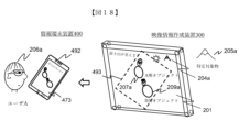
- FIG. 18 is a diagram showing a first example for explaining visual information of the video information display system of the second embodiment.
- FIGS. 19, 20, and 21 are diagrams showing the main processing flow of the first example of the video information display system of the second embodiment.
- the video information creation device 300 has a transparent display 201 as the display 334 for viewing the scenery from within the observation room, and at least one object 204a that is a point of interest from within the observation room, such as Mt. Fuji or a sunset, displayed. Of these objects of interest 204a, the object selected to guide the user in the direction to look is the specific object. In FIG. 18, the specific object 205a (Mt. Fuji) is selected and displayed highlighted.
- the display 434 is composed of an organic EL display or a liquid crystal display 473.
- the liquid crystal display 473 on the smartphone 492 displays transmission guidance information 493 (shown by a dashed line) including a part or all of the display screen of the transparent display 201.
- the video information creation device 300 in this second embodiment is the same as or has the same functions as the video information creation device 100 of the first embodiment.
- the information terminal device 400 allows the user to freely view the transparent display 201 on a smartphone 492 or the like that is at hand, for example, in situations where it is difficult to view the transparent display 201 directly.
- FIG. 19 shows the processing steps of the video information creation device 300.
- steps that perform the same processes or functions as those in FIG. 3, FIG. 5, FIG. 10, FIG. 12, FIG. 14, and FIG. 16 are given the same reference numerals, and their explanations are omitted.
- the transparent display 201 displays the real world or an image of the real world captured by the outer camera 155, and at the same time, guidance information for user A 206a with an identification object 207a for A is superimposed on the transparent display 201 on the line connecting the user's position and the specific object. Then, out of the display contents of the transparent display 201, transmission guidance information 493 is generated that includes part or all of the guidance information including at least the identification object 207a for A, and is transmitted from the communication interface 360 directly or via the communication line 501 to the information terminal device 400.
- the process in FIG. 19 is repeated in a cycle (e.g., 60, 120, 240 frames per second) in which one image is detected or displayed on the sensor cameras 202a-d or the transparent display 201.
- a cycle e.g., 60, 120, 240 frames per second
- the information terminal device 400 is a smartphone 492 with a built-in liquid crystal display 473.
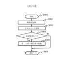
- Figures 20 and 21 show the processing steps of the information terminal device 400.
- step 901 of FIG. 20 the imaging section of the outer camera 455 is started (S902), and a two-dimensional code indicating connection information with the image information creation device 300 is captured on the periphery of the image information creation device 300 or on part of the transparent display 201, and the two-dimensional code is read (S903).
- the information terminal device 400 determines whether or not connection information has been obtained from the read two-dimensional code, and if connection information has not been obtained (S904: No), the process proceeds to step 906 and ends.
- the information terminal device 400 connects the communication interface 460 of the information terminal device 400 to the communication interface 360 of the video information production device 300, and proceeds to step 906 and ends.
- the information terminal device 400 receives the real-world image transmitted from the image information creation device 300 in step 871 and the transmission guide information 493 to which the identification object 207a for user A 206a has been added via the communication interface 360 (S907).
- the display method setting unit 483 detects the display selection mode that has been set in advance in the input/output interface 420 (S908) and determines whether or not to display according to the display selection mode.
- step 911 the identification object 207a for A is not displayed, and other guidance information (for example, a video image of the real world) is displayed (S911).
- the object superimposition unit 481 superimposes (S910) the transmission guidance information 493 including guidance information to which the identification object 207a for A of user A 206a has been added onto the image of the real world received from the image information creation device 300, and displays (S911). Then, the process ends.
- the display selection mode includes not only whether or not to display guidance information, but also whether or not to display only a specific user A, etc.
- the process in FIG. 21 is repeated in a cycle of displaying one image on the LCD display 473 (e.g., 60, 120, 240 frames per second, etc.).
- guidance information with an identification object for each user added is displayed on the transparent display, but if the user wants to see it properly at hand, the display contents of the transparent display including the user's identification object can be displayed on the mobile information terminal at hand as transmission guidance information. This allows the user to visually recognize the guidance information and specific objects for themselves on the information terminal device 400 at hand, improving usability.
- FIG. 22 is a diagram showing a second example for explaining visual information of the video information display system of the second embodiment.
- the information terminal device 400 may have an avatar 475 as a user profile image or an alter-ego that the user has registered in advance.
- the avatar 475 held by the information terminal device 400 is transmitted to the video information creation device 300, and an identification object 476 is generated and displayed using the avatar 475, making it easier to find the user's own familiar identification object 476 among the identification objects of other users.
- Figures 23 and 24 are diagrams showing the main process flow of the second example of the video information display system of the second embodiment.
- the video information creation device 300 in this embodiment is the same as or has the same functions as the video information creation device 300 of the first example.
- Figure 23 shows the processing steps of the information terminal device 400. In Figure 23, steps that process the same processes or perform the same functions as in Figures 20 and 21 are given the same reference numerals, and their explanations will be omitted.
- step 921 the information terminal device 400 transmits avatar information including an image of the avatar 475 preregistered in the smartphone 492 from the communication interface 460 via the communication interface 360 of the video information creation device 300.
- FIG. 24 shows the processing steps of the video information creation device 300.
- steps that perform the same processes or functions as those in FIG. 3, FIG. 5, FIG. 10, FIG. 12, FIG. 14, FIG. 16, and FIG. 19 are given the same reference numerals, and their explanations are omitted.
- step 875 the video information creation device 300 receives the avatar 475 that was previously registered in the smartphone 492.
- the visual information generation unit 390 changes the identification object created in step 803 to the avatar 475, and displays the information in the processing from step 805 onwards.
- the visual information generation unit 390 displays the guidance in the processing from step 805 onwards without changing the identification object created in step 803.
- the process in FIG. 24 is repeated in a cycle (e.g., 60, 120, 240 frames per second) in which one image is detected or displayed on the sensor cameras 202a, 202b, 202c, 202d or the transparent display 201.
- a cycle e.g., 60, 120, 240 frames per second
- the avatar used by the user can be used as an identification object added to the guidance information, making it easier for the user to find guidance information relevant to them.
- the third embodiment is an extension of the second embodiment, and is an embodiment in which, when the user is in a position where the video information creation device 300 cannot be seen directly by the user, the information terminal device 400 is used to guide the user to a position where the video information creation device 300 can be seen.
- the information terminal device 400 of the third embodiment is, for example, a portable smartphone, a tablet terminal, a personal computer, a head-up display, or the like, as described in Figs.
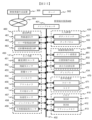
- FIG. 25 is a diagram showing the functional block configuration of an information terminal device of the third embodiment.
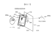
- FIGS. 26 and 27 are diagrams showing a first example for explaining visual information of an information terminal device of the third embodiment.
- FIGS. 28 and 29 are diagrams showing the main processing flow of the first example of an information terminal device of the third embodiment.
- FIGS. 30 and 31 are diagrams showing the main transmission/reception processing flow of the first example of an information terminal device of the third embodiment.
- the information terminal device 400 in this embodiment includes a main processor 401, a memory 410, an input/output interface 420, a video information processing unit 480, a sensor group 450, a communication interface 460, an audio processing unit 470, etc. These components are connected to each other via a bus 402. The details of each part are as explained in Figures 17 to 24 of the second embodiment.
- the communication interface 460 connects directly or via a communication line 501 to the video information creation device 300 and related servers 502 to send and receive information.
- the image information creation device 300 is attached to the wall 511 inside the observation room.
- the specific object 205a (Mt. Fuji) is blocked by the wall 511 inside the observation room from the position of user A 206a. Therefore, the image information creation device 300 transmits transmission guidance information to the information terminal device 400, informing the user that the specific object 205a is visible through the transparent display of the image information creation device 300.
- the smartphone 492 and the liquid crystal display 473 display the image captured by the rear camera 455 and Mount Fuji, the sunset, and other objects of interest 512 that can be seen from the observation room.
- User A 206a can see from the video information 514 on the LCD display 473 of the smartphone 492 that the specific object 205a (Mt. Fuji) is visible from the video information creation device 300.
- FIG. 27 shows the case where the user moves according to the guidance in FIG. 26 and arrives at a position where the specific object 205a (Mt. Fuji) can be seen through the transparent display of the image information creation device 300.
- user A is present within the angle of view of in-camera 454, and when an image of a virtual line of sight connecting user A 206a and specific object 205a (Mt. Fuji) captured by out-camera 455 is present on the image captured by out-camera 455 of information terminal device 400, guidance information 513 indicating the direction of specific object 205a (Mt. Fuji) and image information 514 of specific object 205a (Mt. Fuji) as seen from image information creation device 300 are displayed on the image on liquid crystal display 473.
- the virtual line of sight is not the user's line of sight because there is wall 511, but the user's virtual line of sight calculated by image information creation device 300, and if wall 511 were transparent, it would be the line when the user views specific object 205a.
- the guidance information 513 uses the avatar 475 registered on the smartphone 492 as described in the second example of the video information display system of the second embodiment in FIG. 22.
- Step 931 ends with displaying the image captured by the outer camera 455 and the surrounding objects of interest 512 on the LCD display 473.
- the user 206a selects from among the objects 512 exemplified in step 931 of FIG. 28, or freely sets the name of a specific object 205 using the touch panel 422 on the LCD display 473 (S932).
- step 911 If a specific object 205 has not been set (S933: No), the process proceeds to step 911 and the object overlay unit 481 ends without overlaying the guidance information 513.
- the object superimposition unit 481 determines that a specific object 205 has been set (S933: Yes)
- the object superimposition unit 481 acquires the position information of the information terminal device 400 using the satellite positioning sensor 451 or the like (S934).
- the information terminal device 400 transmits the image captured by the outer camera 455, the position information of the specific object 205, and the terminal position information to the image information creation device 300 (S935).
- the video information creation device 300 creates guidance information 513 if there is a line connecting the user 206a (using the terminal location information owned) and the specific object 205a within the received captured video.
- the information terminal device 400 receives the video of the real world captured by the rear camera 155 of the video information creation device 300 and the guidance information 513 (S936), processes the guidance information for display (S911), and then ends the process.
- Steps 935 and S936 in Figures 30 and 31 are the same processes as those in Figures 29 and 30.
- Figure 30 explains the processing within the information terminal device 400.
- the image information creation device 300 receives it (S951). Based on the terminal position information received by the image information creation device 300, the received captured image is compared with 3D map information from a VPS (Visual Positioning System) that has previously generated an indoor map using detailed captured images of the building and distance sensors, etc., and is capable of measuring the image by correlating it with a world coordinate system, to determine a more accurate terminal position (S952).
- VPS Visual Positioning System
- the video information creation device 300 calculates the line connecting this more accurate terminal position information and the specific object 205a (Mt. Fuji) and the position information on the received captured image, and calculates the specific object display position information (S953).
- the image information creation device 300 receives an image of the display 334 (134) of the image information creation device 300 and replaces the image with an image of the real world captured by the outer camera 355 (155) of the image information creation device 300, the image information creation device 300 transmits the image and the specific object display position information (S954).
- the information terminal device 400 receives this information (S936) and executes the guidance information display process to display it (S911).
- the information terminal device 400 transmits a request for indoor map information (S935a), which is received by the video information creation device 300 (S961).
- the video information creation device 300 creates and transmits indoor map information (S962), which is received by the information terminal device 400 (S936a).
- the information terminal device 400 transmits a request for specific object information (S935b), and the video information creation device 300 receives the request for specific object information (S963).
- the video information creation device 300 transmits the specific object information (S964), and the information terminal device 400 receives it (S936b).
- the information terminal device 400 transmits a request for video information from the video information creation device 300 (S935c), which is received by the video information creation device 300 (S965).
- the video information creation device 300 transmits video information captured by the outer camera 155 of the video information creation device 300 (S966), which is received by the information terminal device 400 (S936c).
- the position information creation unit 482 of the information terminal device 400 calculates the position of the guidance information, and the object superimposition unit 481 superimposes the guidance information 513. As described above, the guidance information to be displayed in step 911 is created by the information terminal device 400.
- the second example provides a method for guiding to the position of the image information production device 300 in an observation deck where the specific object 205a (Mt. Fuji) can be seen from a more distant position than in the first example.
- FIGS. 32 and 33 are diagrams showing a second example and another example for explaining visual information of the information terminal device of the third embodiment.
- FIG. 34 is a diagram showing the main processing flow of the second example of the information terminal device of the third embodiment.
- FIG. 35 is a diagram showing the transmission/reception processing flow with the server 502 of the second example of the information terminal device of the third embodiment.
- the same symbols are used for parts that are the same or have the same functions as those in FIGS. 26 and 27, and their explanations are omitted.
- the smartphone 492 displays on the liquid crystal display 473 the image captured by the rear camera 455, the positions of windows (image information creation device 300) of multiple observation rooms etc. from which the specific object 205a (Mt. Fuji) close to the current location can be seen, and image information 488, 489 of the specific object 205a (Mt. Fuji) visible from those positions. Furthermore, the smartphone 492 displays map information 498 to that point and guidance information (directions to the building 484, 485 and indoor guidance inside the building 486, 487) on the liquid crystal display 473.
- FIG. 34 steps that perform the same processes or functions as those in FIG. 20, FIG. 21, FIG. 23, FIG. 28, and FIG. 29 are given the same reference numerals, and their description will be omitted.
- step 971 the information terminal device 400 (smartphone 492) determines whether there are multiple locations from which the specific object 205a (Mount Fuji) received in step 936 can be seen, and if there are not multiple locations (S971: No), it displays the guidance information (S911).
- Video information 488, 489 of the specific object 205a (Mt. Fuji) that can be seen from each of the multiple locations is displayed as information for this selection.
- the video information 488, 489 displayed at this time may be current video of the location (video information creation device 300) received via server 502, or it may predict the time it will take to reach the location from the current position and display video that will be visible at that time from past video. This is particularly effective when the specific object 205e (sunset) is constantly moving.
- the information terminal device 400 transmits information about the specified location to the server 502 (S973), receives guidance information (FIG. 33) to the specified location from the server 502 (S974), and guides the user to a location where the specific object 205a (Mt. Fuji) can be seen (S911).
- Steps S935(d, e), S936(d, e), and S951(d, e) to S954(d, e) in FIG. 35 are the same processes as those in FIG. 29, FIG. 30, and FIG. 31.
- the server 502 receives them (S951d) and, based on the received terminal location information, compares the received captured image with the VPS's three-dimensional map information that has been created in advance by extracting characteristic parts from satellite images, images taken while driving around on roads and sidewalks, and information taken inside buildings, to determine a more accurate terminal location (S952).
- the server 502 calculates the specific object display position information (S953), and if there are multiple image information creation devices 300 from which the specific object can be seen in the received captured image, the server 502 obtains images of the real world as seen by each image information creation device 300 and transmits this information (S954d), which is received by the information terminal device 400 (S936d).
- the information terminal device 400 displays multiple locations as shown in FIG. 33, and the user specifies the location he or she wants to view from among the multiple locations (S981).
- the information terminal device 400 transmits information about the specified location (S982), and the server 502 receives the information about the specified location (S983).
- the server 502 again transmits the specific object location guidance information for only the specified location and the image from the image information creation device (S954e), which is received by the information terminal device 400 (S936e) and executes the display process of the guidance information (S911).
- the process in FIG. 34 is repeated in a cycle of capturing or displaying one image on the outer camera 455 or display 434 (e.g., 60, 120, 240 frames per second, etc.).
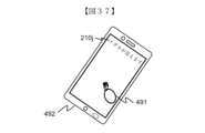
- FIGS. 36 and 37 are diagrams showing a third example and another example for explaining visual information of the information terminal device of the third embodiment.
- the liquid crystal display of the smartphone 492 in FIG. 36 displays a message 210j indicating that a specific object, such as a small fish in an aquarium tank, can be seen.
- the LCD display of the smartphone 492 also displays an identification object 523 for A that provides guidance information to the user A 206a in the situation shown in FIG. 27 of the first example, and an identification object 491 for C that provides guidance information if a user C who does not own a smartphone is nearby.
- user A selects identification object 491 for C on smartphone 492 and lends smartphone 492 to user C, so that similar guidance information (FIG. 37) can be provided to user C who does not own a smartphone (or does not use the present invention).
- This display mode change is performed in the process shown in steps 908 to S910 of FIG. 21.
- FIG. 38 is a diagram showing a fourth example for explaining visual information of the information terminal device of the third embodiment.
- a pair of glasses-type smart glasses 495 is shown as one of the present embodiments. Smart glasses are convenient for hands-free use and are suitable for the purpose of providing guidance information of the present invention.
- All of the components of the information terminal device 400 shown in FIG. 25 may be built in, but at least an outer camera 496, a display 497, and a part of the communication interface 460 may be built in, and the other components may be realized by wireless communication with a separately owned smartphone 492.
- each processing example may be independent programs, or multiple programs may constitute a single application program. Furthermore, the order in which each process is performed may be changed.
- the functions of the present embodiment described above may be realized in part or in whole by hardware, for example, by designing them as an integrated circuit. They may also be realized in software by a microprocessor unit, CPU, etc. interpreting and executing an operating program that realizes each function.
- the scope of software implementation is not limited, and hardware and software may be used together.
- Each function may also be realized in part or in whole by a server.
- the server may be any type of server as long as it can execute functions in cooperation with other components via communication, such as a local server, cloud server, edge server, or net service.
- Information such as programs, tables, and files that realize each function may be stored in a memory, a recording device such as a hard disk or SSD (Solid State Drive), or a recording medium such as an IC card, SD card, or DVD, or may be stored in a device on a communication network.
- a recording device such as a hard disk or SSD (Solid State Drive), or a recording medium such as an IC card, SD card, or DVD, or may be stored in a device on a communication network.
- control lines and information lines shown in the diagram are those considered necessary for explanation, and do not necessarily represent all control lines and information lines on the product. In reality, it can be assumed that almost all components are interconnected.
- a video display method comprising: The processor: A user position acquisition step of acquiring a user position; a specific object position acquisition step of acquiring position information of a specific object to be guided to the user as an object that the user should pay attention to; a region calculation step of calculating a region where a virtual line connecting the position of the user and the position of the specific object intersects with a display; an identification object generating step of generating an identification object for identifying the user; a display step of adding the identification object to guidance information indicating the position of the specific object and displaying the information in an area where the virtual line intersects with a display.
- Image display method comprising: The processor: A user position acquisition step of acquiring a user position; a specific object position acquisition step of acquiring position information of a specific object to be guided to the user as an object that the user should pay attention to; a region calculation step of calculating a region where a virtual line connecting the position of the user and the position of the specific object intersects with a display; an identification object generating step of generating an
- a video information creation device comprising: A processor; With the in-camera, With the rear camera, A display; The processor, Acquire a user's position based on the image of the front camera; acquiring position information of a specific object to be guided to the user as an object that the user should pay attention to based on the image captured by the outer camera; Calculating an area where a virtual line connecting the position of the user and the position of the specific object intersects with the display; generating an identity object that identifies the user; adding the identification object to guidance information indicating the position of the specific object, and displaying the information in a region where the virtual line intersects with the display; Video information creation device.
- the video information creation device is A first processor; With the in-camera, With the rear camera, A first display; A first communication device, The first processor, Acquire a user's position based on the image of the front camera; acquiring position information of a specific object to be guided to the user as an object that the user should pay attention to, based on the image captured by the outer camera; Calculating an area where a virtual line connecting the position of the user and the position of the specific object intersects with the first display; generating an identity object that identifies the user; adding the identification object to guidance information indicating the position of the specific object, and displaying the information in a region where the virtual line intersects with the first display; a display screen on which the identified object and the guidance information are displayed on the first display is transmitted from the first communication device to an information terminal device as transmission guidance information;
- the information terminal device A second processor; and A second display; and A second communication device,
- the information terminal device A second processor; and A second display; and A second communication device, The
- Video information creation device 101 Main processor 102: Bus 110: Memory 111: RAM 112: ROM 113: Flash memory 120: Input/output interface 121: Button switch 122: Touch panel 134: Display 150: Sensor group 151: Satellite positioning sensor 152: Geomagnetic sensor 153: Distance sensor 154: In-camera 155: Out-camera 156: Other sensor 157: Detection sensor 160: Communication interface 161: Wireless communication interface 162: User information communication interface 163: Short-range wireless communication interface 170: Audio processing unit 171: Speaker 172: Microphone 180: Video information processing unit 181: Object superimposition unit 182: Position information creation unit 183: Display method setting unit 190: Visual information generation unit 191: Object generation unit 192: Display method change unit 193: User recognition unit 194: Gaze position detection unit 201: Transparent display 202a: Sensor camera 202b : sensor camera 202c : sensor camera 202d : sensor camera 203a : sensor camera 203b : sensor
Landscapes
- Engineering & Computer Science (AREA)
- Physics & Mathematics (AREA)
- Computer Hardware Design (AREA)
- General Physics & Mathematics (AREA)
- Theoretical Computer Science (AREA)
- User Interface Of Digital Computer (AREA)
Abstract
映像表示方法であって、プロセッサが、ユーザの位置を取得するユーザ位置取得ステップと、前記ユーザに対して注目すべき対象物として案内を行う特定対象物の位置情報を取得する特定対象物位置取得ステップと、前記ユーザの位置と前記特定対象物の位置とを結ぶ仮想線がディスプレイに交わる領域を算出する領域算出ステップと、前記ユーザを識別する識別オブジェクトを生成する識別オブジェクト生成ステップと、前記特定対象物の位置を示す案内情報に前記識別オブジェクトを付加して、前記仮想線がディスプレイに交わる領域に表示する表示ステップと、を含む。
Description
本技術は、映像表示方法、映像表示装置、及び映像情報表示システムに関し、特に、AR(Augmented Reality)を用いて目的とする対象物を見つける為の案内をする映像情報作成装置、映像情報表示システム、情報端末装置に関する。
特許文献1は「情報処理装置は、複数のユーザの視界に重ね合わせて表示する視覚情報の表示方法を設定する表示方法設定部と、設定された前記表示方法により前記視覚情報の表示を制御する表示制御部とを備え、前記表示方法は、ユーザ毎に個別に前記視覚情報を表示する個別表示、及び、複数のユーザに対する前記視覚情報を統合して表示する統合表示を含む。本技術は、例えば、ARを用いて視覚情報を表示する車両に適用することができる(要約抜粋)。」との記載を開示している。
特許文献1に記載の発明は、車載用のHUD(ヘッドアップディスプレイ)において、ステレオカメラで対象物までの距離を測定し、対象物と同じ位置に映像(視覚情報)の焦点を合わせることにより、運転者の視点が横にずれても、視覚情報と対象物の位置をずれにくくする技術である。従って車両の運転者は一人であることから、特許文献1では、複数のユーザが、様々な位置から見ることは考慮されていない。
従って、例えば展望室等の観光案内などで、見どころである対象物が視認できる案内情報を複数のユーザに同時に提供したい状況に特許文献1を適用しようとしても、複数のユーザは異なる視点位置から対象物を探そうとしているため、各ユーザから見て適切な案内が行えず誤った方向に視線を誘導したり、各ユーザに対する案内を同時に行うと誰に対する案内なのかが不明になったりするという課題が残る。
本発明は上記課題を解決するためになされたものであり、複数のユーザの其々からみた対象物の存在する方向を同時に案内することを目的とする。
上記課題を解決するために、本発明は請求の範囲に記載の構成を備える。
本発明によれば、複数のユーザの其々からみた対象物の存在する方向を同時に案内することができる。なお、上記した以外の課題、構成及び効果は、以下の実施形態の説明により明らかにされる。
本発明は、仮想現実オブジェクトを表示して同一空間にいる複数のユーザに対して同時に観賞を進める特定対象物の案内を行うことで、労働集約型の産業に対して仮想現実表示のより効果的な利用を創出のための技術の向上が見込めることから、国連の提唱する持続可能な開発目標(SDGs:Sustainable Development Goals)の8.2(商品やサービスの価値をより高める産業や、労働集約型の産業を中心に、多様化、技術の向上、イノベーションを通じて、経済の生産性をあげる)に貢献することが期待できる。
以下、図面等を用いて、本発明の一実施形態及び各種実施例について説明する。以下の説明は本発明の内容の具体例を示すものであり、本発明がこれらの説明に限定されるものではなく、本明細書に開示される技術的思想の範囲内において当業者による様々な変更および修正が可能である。また、本発明を説明するための全図において、同一の機能を有するものは、同一の符号を付け、その繰り返しの説明は省略する場合がある。以下、全実施形態に共通する事項について説明し、続いて各実施形態の特徴について説明する。なお、ここに記載された効果は必ずしも限定されるものではなく、本開示中に記載された何れかの効果であってもよい。
本実施の形態における映像情報作成装置100は、大中小規模の展望室や、ビルの窓、学校の窓、列車や観光バス等の車の窓、HUD、水槽内に見える特定対象物の方向を複数のユーザ毎に同時に案内を表示する。
(第一実施形態)
図1Aは本発明の第一実施形態の映像情報作成装置のハードウェア構成図である。図1Bは本発明の第一実施形態の映像情報作成装置の機能ブロック構成を示す図である。
図1Aは本発明の第一実施形態の映像情報作成装置のハードウェア構成図である。図1Bは本発明の第一実施形態の映像情報作成装置の機能ブロック構成を示す図である。
本実施の形態における映像情報作成装置100は、例えば透過ディスプレイ、ヘッドアップディスプレイ、スマートフォン、タブレット端末、パソコン等である。
図1Aに示すように、映像情報作成装置100は、メインプロセッサ101、メモリ110、入出力インターフェイス120、ディスプレイ134、センサ群150、通信インターフェイス(I/F)160、音声処理部170を備えている。これらの構成要素はバス102を介して互いに接続されている。
メモリ110は、RAM111、ROM112、フラシュメモリ113等を含む。
入出力インターフェイス120は、各種のボタンスイッチ121、タッチパネル122等を含む。
ディスプレイ134は背後が透けて見える透過ディスプレイ(透過型有機ELディスプレイ、透過型無機ELディスプレイ、透過型LCDディスプレイ等の他、投影された情報を反射表示できるガラスを含む)等で構成される。
センサ群150は、衛星測位センサ151、地磁気センサ152、距離センサ153、インカメラ154、アウトカメラ155、その他センサ156等を含む。
通信インターフェイス160は、無線通信インターフェイス161、ユーザ情報通信インターフェイス162、近距離無線通信インターフェイス163等を含む。
音声処理部170は、音声出力装置としてのスピーカ171、及び音声入力装置としてのマイク172を備えている。
メモリ110は、映像情報作成装置100全体をメインプロセッサ101にて制御するためのプログラム等を記憶する。各構成要件で処理される各種データ等がバス102経由で一時記憶される。
入出力インターフェイス120の動作は以下のとおりである。各種のボタンスイッチ121は例えば本機能の動作をオン又はオフにするスイッチである。
タッチパネル122はディスプレイ134上に表示させたボタン等をタッチさせて入力する手段などで構成される。
センサ群150の動作は以下のとおりである。衛星測位センサ151はGPS(Global Positioning System)に代表される衛星測位システムで位置を測定するためのセンサで、複数のGPS衛星からの信号を受信して高精度な三次元の現在地情報を得る。なお、GPSで行う測位精度の向上のために収集データの補強・補正することを目的に利用されているSBAS(補強衛星群)としてのRNSS(地域広報衛星システム)を利用してもよい。
地磁気センサ152は地球の磁力を検出し二次元や三次元の方向を計測する。
距離センサ153は超音波やレーザ光をパルス発光させ対象物にあたって戻ってくるまでの時間を計測する方法等にて距離を測定する。
インカメラ154はディスプレイ134を見ているユーザ側を撮影する撮像機である。
アウトカメラ155はユーザから見てディスプレイ134の先にあるものを撮影する撮像機である。
その他センサ156は周辺環境(明るさ、温度、騒音等)等の必要な情報を得るための検出器である。
通信インターフェイス160の動作は以下のとおりである。無線通信インターフェイス161は4G/5G等の移動体通信に用いられる無線通信の送受信機能を有するインターフェイスである。
無線通信インターフェイス161は外部ネットワーク上のサーバとの間で必要な情報を取得することができる。
ユーザ情報通信インターフェイス162はWiFi(登録商標)等に代表される中距離無線通信の送受信機能を有するインターフェイスである。
近距離無線通信インターフェイス163はBluetooth(登録商標)やNFC(Near Field Communication)等の近距離無線通信の送受信機能を有するインターフェイスである。
図1Bを示すように、映像情報作成装置100は、主な機能ブロックとして映像情報処理部180及び視覚情報生成部190を含む。
映像情報処理部180は、オブジェクト重畳部181、位置情報作成部182、表示方法設定部183を含む。
視覚情報生成部190には、オブジェクト生成部191、表示方法変更部192、ユーザ認識部193、及び視線位置検出部194を含む。
映像情報処理部180の動作は以下のとおりである。
位置情報作成部182はオブジェクト生成部191または表示方法変更部192にて作成されたユーザ毎のオブジェクトをディスプレイ134上のどの位置に配置するかを演算処理して求める。
表示方法設定部183は映像情報の表示方法を設定する。
オブジェクト重畳部181はオブジェクト生成部191または表示方法変更部192にて作成されたユーザ毎のオブジェクトを位置情報作成部182にて求められた配置位置に重畳表示する。
視覚情報生成部190の動作は以下のとおりである。
ユーザ認識部193はインカメラ154等にてユーザを検出して認識する。
オブジェクト生成部191はユーザ認識部193にて認識したユーザ毎の識別を可能にするオブジェクトを作成する。
視線位置検出部194は、ユーザ毎にディスプレイ134のどの部分が見えているか否かを検出する。
表示方法変更部192はユーザ毎の識別オブジェクトの表示が互いに重なり合ったりする等で上手く表示できないときにその表示方法を適宜変更する。
上記映像情報処理部180及び視覚情報生成部190に含まれる各部は、メモリ110に格納された本実施形態に係る映像表示プログラムをメインプロセッサ101が実行することによりハードウェアとプログラムとが協働して構成され、各部の機能が実現する。
(第一実施形態の第一例)
第一例は、ユーザに対してみる方向を案内する対象物である特定対象物が静止物である点に特徴がある。図2は第一実施形態の映像情報作成装置の視覚情報を説明するための第一例を示す図である。図3は第一実施形態の映像情報作成装置の第一例の主な処理フローを示す図である。
第一例は、ユーザに対してみる方向を案内する対象物である特定対象物が静止物である点に特徴がある。図2は第一実施形態の映像情報作成装置の視覚情報を説明するための第一例を示す図である。図3は第一実施形態の映像情報作成装置の第一例の主な処理フローを示す図である。
図2において、映像情報作成装置100は、ディスプレイ134として展望室内からの景色を眺めるための透過ディスプレイ201、インカメラ154として透過ディスプレイ201の四隅の内側に配置されたセンサカメラ202a、202b、202c、202dの4個、アウトカメラ155として透過ディスプレイ201の四隅の外側に配置されたセンサカメラ203a、203b、203c、203dの4個を備える。なお、インカメラ154およびアウトカメラ155として配置するカメラの数や位置は一例であり、所望の映像が撮影できるのでれば、図2と異なる個数、異なる位置でも良い。また、他の図面においても同様である。
展望室内からの見どころとなる少なくとも一つ以上の対象物204aとして、富士山や夕日等が表示される。それら見どころとなる対象物204aのうち、ユーザに対してみる方向を案内するものとして選択された対象物が特定対象物である。特定対象物は少なくとも一つの対象物204aの中から所定時間間隔で一つずつ順次選択される。図2では、特定対象物205a(富士山)が選択されているとする。特定対象物の選択処理は、オブジェクト生成部191が行ってもよいし、ユーザが例えば案内を希望する特定対象物の名称を口頭で発話すると、マイク172が集音し、オブジェクト生成部191が音声解析を行って特定対象物の選択を行ってもよい。
オブジェクト重畳部181はユーザA206aが特定対象物205a(富士山)を見た視線上にある透過ディスプレイ201上の領域にA用の識別オブジェクト207aを付加した案内情報を表示する。なお、ここでいう「ユーザA206aが特定対象物205a(富士山)を見た視線上にある透過ディスプレイ201上の領域」とはユーザが現在いる位置から特定対象物205aを視認した際の視線であり、ユーザが特定対象物を見ていないときの視線でない。よって、より正確にはオブジェクト重畳部181は、ユーザの位置と前記特定対象物の位置とを結ぶ仮想線がディスプレイに交わる領域を求め、この領域をA用の識別オブジェクト207aを表示する領域として用いる。以下の説明においても同様である。案内情報は、特定対象物の一部又は全部を包含する図形であり、識別オブジェクトを付加することで、どのユーザに対する案内情報であるかがわかる。
さらにオブジェクト重畳部181はユーザB208aが特定対象物205a(富士山)を見た視線上にある透過ディスプレイ201上の領域にB用の識別オブジェクト209aを付加した案内情報を表示する。この時、オブジェクト重畳部181は、透過ディスプレイ201上の左上に「富士山が見えます」などの文字情報210を表示する。なお、対象物204aや文字情報210は予め映像情報作成装置100の設置場所に応じてメモリ110に記憶される。
次に図3を参照して、第一実施形態の第一例の処理の流れを説明する。
図3に示すように、映像情報作成装置100が起動(開始)すると(S801)、透過ディスプレイ201の四隅の内側に配置されたセンサカメラ202a、202b、202c、202dの4個から得た撮像データに基づいて、ユーザ認識部193が透過ディスプレイ201を通して室外の景色を見ているユーザ(ユーザA206aやユーザB208a)を認識する(S802)。
またステップ802では、位置情報作成部182が予め把握している特定対象物205a(富士山)と透過ディスプレイ201の三次元配置情報と新たに得られたユーザA206aやユーザB208aの三次元位置情報を把握する。より正確には位置情報作成部182はユーザA206aやユーザB208aの位置情報として各ユーザの目の位置情報を検出する。
続いてオブジェクト生成部191は、検出したユーザA206aとユーザB208aを個別に識別できるように異なるA用の識別オブジェクト207aとB用の識別オブジェクト209aを作成する(S803)。
次に位置情報作成部182は、ユーザA206a及びユーザB208aが透過ディスプレイ201を透過して特定対象物205a(富士山)が見える位置にいるか否かを判断する(S804)。ステップ804にてユーザA206a及びユーザB208aが特定対象物205a(富士山)を見える位置にいないと判断(S804:No)した場合はA用の識別オブジェクト207aとB用の識別オブジェクト209aを出力せず、そのままステップ808に進んでその他の案内情報表示処理を行いステップ809にて終了する。
一方、位置情報作成部182がユーザA206a及びユーザB208aが特定対象物205a(富士山)を見える位置にいると判断(S804:Yes)した場合はステップ805にて特定対象物205a(富士山)とユーザA206a及びユーザB208aを結ぶ透過ディスプレイ201上にA用の識別オブジェクト207aとB用の識別オブジェクト209aを表示する位置を算出する(S805)。なお、特定対象物と透過ディスプレイ間の距離が透過ディスプレイとユーザ間の距離及びユーザ同士の距離より十分遠い場合は、ユーザが特定対象物を見ている方向はほぼ等しいと考えられる。このため、ユーザ毎のオブジェクト表示位置の算出は、予め透過ディスプレイに対する特定対象物への3次元の方向ベクトルを算出しておき、ユーザの位置に応じて方向ベクトルを平行移動することにより識別オブジェクトの位置を簡易的に算出し、演算処理量を低減してもよい。他の実施形態でも同様である。
そして位置情報作成部182が透過ディスプレイ201上にてユーザ毎の複数の識別オブジェクトが隣接または重なるか否かを判断する(S806)。ユーザ毎の複数の識別オブジェクトが隣接または重なると判断(S806:Yes)した複数の識別オブジェクトは、表示方法変更部192が後で述べる統合オブジェクトに変更したものを出力し(S807)、オブジェクト重畳部181が透過ディスプレイ201上に統合オブジェクトを表示し(S808)、特定対象物205a(富士山)が見える位置を案内する。そしてステップ809にて終了とする。
一方、そして位置情報作成部182がユーザ毎の複数の識別オブジェクトが隣接または重ならないと判断(S806:No)した場合はオブジェクト生成部191がA用の識別オブジェクト207aとB用の識別オブジェクト209aを出力し、オブジェクト重畳部181が透過ディスプレイ201上に識別オブジェクト(A用の識別オブジェクト207aとB用の識別オブジェクト209a)を付加した案内情報を表示し(S808)、特定対象物205a(富士山)が見える位置を案内する。そしてステップ809にて終了とする。
図3の処理はセンサカメラ202a、202b、202c、202dまたは透過ディスプレイ201に一枚の映像を検出または表示するサイクル(例えば、毎秒60、120、240枚など)にて繰り返し行う。
なお、図3の処理ステップでは説明していないが、メインプロセッサ101は文字情報210をスピーカ171から音声案内情報として出力してもよい。
また、透過ディスプレイ201上には現実の世界を透過して見る例にて説明したが、センサカメラ203a~dを用いた現実の世界を撮影した映像を表示することもできる。これにより、特定対象物が天候や昼夜などの影響で見えないときに過去の撮影した映像を表示することができるなどの効果もある。
(第一実施形態の第二例)
第二例は、特定対象物が動体である点に特徴がある。以下では、特定対象物として夕日を例に挙げる。夕日のユーザに対する位置は時々刻々動く。図4は第一実施形態の映像情報作成装置の視覚情報を説明するための第二例を示す図である。図5は第一実施形態の映像情報作成装置の第二例の主な処理フローを示す図である。第二例は第一例に対して特定対象物205e(夕日)が時々刻々動いている例を示す。図4において、図2と同じまたは同じ機能を有するものには同じ符号を付し、その説明は省略する。
第二例は、特定対象物が動体である点に特徴がある。以下では、特定対象物として夕日を例に挙げる。夕日のユーザに対する位置は時々刻々動く。図4は第一実施形態の映像情報作成装置の視覚情報を説明するための第二例を示す図である。図5は第一実施形態の映像情報作成装置の第二例の主な処理フローを示す図である。第二例は第一例に対して特定対象物205e(夕日)が時々刻々動いている例を示す。図4において、図2と同じまたは同じ機能を有するものには同じ符号を付し、その説明は省略する。
映像情報作成装置100は、透過ディスプレイ201、センサカメラ202a~d、203a~dを備える。展望室内からの見どころとなる対象物204eの例として夕日が表示され、特定対象物205e(夕日)の案内情報が表示されている。
オブジェクト重畳部181はユーザA206eが特定対象物205e(夕日)を見た視線上にある透過ディスプレイ201上の領域にA用の識別オブジェクト207eを表示する。同じくオブジェクト重畳部181はユーザB208eが特定対象物205e(夕日)を見た視線上にある透過ディスプレイ201上の領域にB用の識別オブジェクト209eを表示する。この時、透過ディスプレイ201上の左上に「夕日が見えます」などの文字情報210eを表示する。
次に図5を参照して、第一実施形態の第二例の処理の流れを説明する。図5において、図3と同じ処理または同じ機能を処理するステップには同じ符号を付し、その説明は省略する。
図5に示すように、映像情報作成装置100が起動(開始)すると(S801)、透過ディスプレイ201の四隅の外側に配置されたセンサカメラ203a、203b、203c、203dの4個から得た撮像データに基づいて位置情報作成部182が特定対象物205e(夕日)を検出する(S812)。
位置情報作成部182が特定対象物205e(夕日)を検出できない場合は(S813:No)した場合は、オブジェクト生成部191は識別オブジェクトを出力せず、そのままステップ808に進んでその他の案内情報表示処理を行いステップ809にて終了とする。
一方、位置情報作成部182が特定対象物205e(夕日)を検出できていると判断(S813:Yes)した場合は、位置情報作成部182は特定対象物205e(夕日)の位置をセンサカメラ203a、203b、203c、203dの出力から算出する(S814)。
特定対象物205e(夕日)が太陽のような天体の場合は、位置情報作成部182は映像情報作成装置100の世界座標系における位置情報を衛星測位センサ151等にて算出すし、無線通信インターフェイス161から外部ネットワーク上のサーバとの間で通信を行い、当該映像情報作成装置100の位置におけるその時刻がわかれば天体の位置情報を取得してもよい。
またセンサカメラ203a~dには距離センサ153の機能を設けておく。そして位置情報作成部182は特定対象物がより近い飛行機や鳥や水槽の魚などの場合はセンサカメラ203a~dのうち少なくとも2つ以上の出力を用いた三角測量などで逐次特定対象物の動きを算出してもよい。以下、ステップ802~S809は図3と同様の処理を行う。
図5の処理はセンサカメラ202a~d、センサカメラ203a~dまたは透過ディスプレイ201に一枚の映像を検出または表示するサイクル(例えば、毎秒60、120、240枚など)にて繰り返し行う。
本第二例では、特定対象物205e(夕日)が逐次動く例を説明したが、同様に映像情報作成装置100が列車や観光バス等の窓につけられた場合に映像情報作成装置100の位置も逐次動くために、ステップ814にて映像情報作成装置100の位置を衛星測位センサ151等にて算出して相対的な位置を逐次算出することで実現する。
(識別オブジェクト生成例)
図6は第一実施形態の映像情報作成装置のオブジェクト生成部191及びステップ803における識別オブジェクトの作成の第一例を示す図である。図7は第一実施形態の映像情報作成装置のオブジェクトの作成の第二例を示す図である。図8は第一実施形態の映像情報作成装置のオブジェクトの作成の第三例を示す図である。
図6は第一実施形態の映像情報作成装置のオブジェクト生成部191及びステップ803における識別オブジェクトの作成の第一例を示す図である。図7は第一実施形態の映像情報作成装置のオブジェクトの作成の第二例を示す図である。図8は第一実施形態の映像情報作成装置のオブジェクトの作成の第三例を示す図である。
図6はユーザ221とステップ803においてオブジェクト生成部191が生成する識別オブジェクト222とを示す。
オブジェクト生成部191はユーザ221の識別情報としてユーザ221の外見的特徴的をインカメラ154にて撮影し、ユーザ221の顔または全身の特徴的な部分(顔形、髪型、眉毛、目、鼻、口、眼鏡、帽子、体形、洋服)を強調して識別する識別オブジェクト222を生成し、表示する。本実施例ではオブジェクト生成部191が特に顔の特徴を抽出して、躯体部は丸い円形として、この円形の中に特定対象物205a、205eが見えるように案内する識別オブジェクト222を作成する。
図7は統合された識別オブジェクトの例を示す。図7では二人のユーザに対する識別オブジェクト223と識別オブジェクト224が隣接または重なる場合にそれぞれの識別オブジェクトの一部を統合して統合オブジェクト225とする。
透過ディスプレイ201上にてユーザ毎の複数の識別オブジェクトが隣接または重なる場合に、表示方法変更部192はステップ807において躯体部の丸い円形を共通に使った統合オブジェクト225を作成する。これにより、二つの識別オブジェクトを重ねて表示するよりも、より見やすくなるように改良している。
図8は統合オブジェクトの他例であり四人のユーザの識別オブジェクト226、227、228、229を統合した統合オブジェクト230を示す。
(第一実施形態の第三例)
第三例はディスプレイ134に近いユーザと遠いユーザの識別オブジェクトが見分けられやすいように改良した技術である。図9は第一実施形態の映像情報作成装置の視覚情報を説明するための第三例を示す図である。図10は第一実施形態の映像情報作成装置の第三例の主な処理フローを示す図である。図9において、図2、図4と同じまたは同じ機能のものには同じ符号を付し、その説明は省略する。
第三例はディスプレイ134に近いユーザと遠いユーザの識別オブジェクトが見分けられやすいように改良した技術である。図9は第一実施形態の映像情報作成装置の視覚情報を説明するための第三例を示す図である。図10は第一実施形態の映像情報作成装置の第三例の主な処理フローを示す図である。図9において、図2、図4と同じまたは同じ機能のものには同じ符号を付し、その説明は省略する。
映像情報作成装置100は、透過ディスプレイ201、センサカメラ202a~d、203a~dを備える。展望室内からの見どころとなる対象物204aとして富士山が選択され、特定対象物205a(富士山)の案内情報が表示されている。
オブジェクト重畳部181はユーザA206fが特定対象物205a(富士山)を見た視線上にある透過ディスプレイ201上の領域にA用の識別オブジェクト207fを表示する。同じくオブジェクト重畳部181はユーザB208fが特定対象物205a(富士山)を見た視線上にある透過ディスプレイ201上の領域にB用の識別オブジェクト209eを表示する。この時、透過ディスプレイ201上の左上に「富士山が見えます」などの文字情報210aを表示する。
第三例では映像情報作成装置100により近いユーザの識別オブジェクトと映像情報作成装置100により遠いユーザの識別オブジェクトとでは、識別オブジェクトの表示態様を変える。表示態様の変更例として、識別オブジェクトの一部または全部のサイズ、解像度、輝度、彩度のうち少なくとも一つ以上を変えてもよい。これにより、各ユーザが自分の識別オブジェクトを見つけやすいように改良している。
次に図10を参照して、第一実施形態の第三例の処理の流れを説明する。図10において、図3、図5と同じ処理または同じ機能を処理するステップには同じ符号を付し、その説明は省略する。
図10に示すステップ831、S832は、表示方法変更部192が処理を実行する。ステップ831において、表示方法変更部192は検出された各ユーザ毎(ユーザA206f及びユーザB208f)に透過ディスプレイ201からの距離を算出する。算出方法は透過ディスプレイ201の四隅の内側に配置されたセンサカメラ202a~dの4個のうち少なくとも2つ以上の出力を用いた三角測量などで算出する。また、センサカメラ202a~dには距離センサ153の機能を設けて距離を算出してもよい。
ステップ832において、表示方法変更部192は各ユーザ毎(ユーザA206f及びユーザB208f)にステップ803にて作成された識別オブジェクトをステップ831で算出した距離に応じて識別オブジェクトの一部または全部のサイズ、解像度、輝度、彩度のうち少なくとも一つ以上を変える。本実施例では距離の近い方のB用の識別オブジェクト209fをB用の識別オブジェクト209fに対して顔の特徴のサイズは変えず全身の丸い円形のサイズを小さくして表示する。
本実施例によれば透過ディスプレイ201に近づいたユーザB208fはより正確な特定対象物205aの見える位置の範囲を絞り込んで案内情報表示することができる。また、他のユーザA206fとの位置関係で自分のB用の識別オブジェクト209fと他のA用の識別オブジェクト207fをより区別しやすくでき透過ディスプレイ201上で自分のオブジェクトを見つけやすくなる。この区別しやすくするためには本実施例のオブジェクトの一部のサイズを変更する以外に解像度、輝度、彩度などを距離に応じて変更しても同様の効果が得られる。
(第一実施形態の第四A例、第四B例、第四C例)
第四A例、第四B例、第四C例はディスプレイ134に近いユーザと遠いユーザの識別オブジェクトが重なった場合には近いユーザの識別オブジェクトを優先的に表示する例である。合わせて遠いユーザの識別オブジェクトを近いユーザの識別オブジェクトの邪魔にならないように表示す方法を視覚情報生成部190と映像情報処理部180にて行う例を示す。図11A、図11B、図11Cは第一実施形態の映像情報作成装置の視覚情報を説明するための第四A例、第四B例、第四C例を示す図である。図12は第一実施形態の映像情報作成装置の第四A例、第四B例、第四C例の主な処理フローを示す図である。図11A、図11B、図11Cにおいて、図2、図4、図9と同じまたは同じ機能のものには同じ符号を付し、その説明は省略する。
第四A例、第四B例、第四C例はディスプレイ134に近いユーザと遠いユーザの識別オブジェクトが重なった場合には近いユーザの識別オブジェクトを優先的に表示する例である。合わせて遠いユーザの識別オブジェクトを近いユーザの識別オブジェクトの邪魔にならないように表示す方法を視覚情報生成部190と映像情報処理部180にて行う例を示す。図11A、図11B、図11Cは第一実施形態の映像情報作成装置の視覚情報を説明するための第四A例、第四B例、第四C例を示す図である。図12は第一実施形態の映像情報作成装置の第四A例、第四B例、第四C例の主な処理フローを示す図である。図11A、図11B、図11Cにおいて、図2、図4、図9と同じまたは同じ機能のものには同じ符号を付し、その説明は省略する。
映像情報作成装置100は、透過ディスプレイ201、センサカメラ202a~d、203a~dを備える。展望室内からの見どころとなる対象物204aの富士山が選択され、特定対象物205a(富士山)の案内情報が表示されている。
図11Aに示す映像情報作成装置の第四A例はディスプレイ134に近いユーザと遠いユーザの識別オブジェクトが重なった場合に近いユーザの識別オブジェクトを優先的に表示する一例である。ユーザA206g及びユーザB208gが特定対象物205a(富士山)を見た視線上にある透過ディスプレイ201上の領域にA用の識別オブジェクト207g(図示せず)及びB用の識別オブジェクト209gの表示が隣接または重なる場合に、オブジェクト重畳部181はディスプレイ134により近いユーザB208gのB用の識別オブジェクト209gを優先的に表示し、ディスプレイ134により遠いユーザA206gのA用の識別オブジェクト207g(図示せず)の一部または全部を表示せず透過ディスプレイ201上の見やすさを向上する。
図12を参照して映像情報作成装置の第四A例の処理の流れを説明する。図12において、図3、図5、図10と同じ処理または同じ機能を処理するステップには同じ符号を付し、その説明は省略する。
ステップ841において表示方法変更部192は、各ユーザ毎(ユーザA206g及びユーザB208g)にステップ806にてA用の識別オブジェクト207g(図示せず)及びB用の識別オブジェクト209gの表示が重なる場合に近いユーザB208gのB用の識別オブジェクト209gを優先的に表示し、遠いユーザA206gのA用の識別オブジェクト207g(図示せず)の一部または全部を出力しない。
なお第一実施形態の第三例の一実施例(図9、図10)を併用すれば、遠いユーザA206gのA用の識別オブジェクト207gは近いユーザB208gのB用の識別オブジェクト209gよりサイズが大きくなることもあり、その場合には優位的に表示したB用の識別オブジェクト209gの背後にA用の識別オブジェクト207gがはみ出して表示されることで遠いユーザA206gも同時にステップ808にて案内情報を表示する。
図11Bに示す映像情報作成装置の第四B例は遠いユーザA206gのA用の識別オブジェクト207g1の表示例の一つである。第四B例ではより近いユーザを優先的に表示する領域外に遠いユーザの識別オブジェクトを表示する。
第四B例では、図12のステップ802において、ユーザ認識部193が各ユーザ(ユーザA206gとユーザB208g)を検出して認識し、位置情報作成部182が各ユーザの配置を演算処理して求める。そしてステップ841おいて、表示方法変更部192は上記ユーザの識別結果及びユーザの配置の演算結果に基づいて遠いユーザA206gから見て近いユーザB208gの陰になって透過ディスプレイ201上が見えない領域に重なるA用の識別オブジェクト207g1を表示しないようにする(図11Bの破線部)。
これにより近いユーザのオブジェクト表示をより見やすくできる。なお、遠いユーザのオブジェクトは遠くからも見えやすいように拡大表示してもよい。
図11Cに示す映像情報作成装置の第四C例は遠いユーザA206gのA用の識別オブジェクト207g2の異なる表示例の一つである。第四C例は近いユーザを優先的に表示する領域外であって、遠いユーザの識別オブジェクトをより積極的に拡大表示して遠くからも見やすく表示する。
第四C例では、図12のステップ832において、表示方法変更部192は遠いユーザAのA用の識別オブジェクトを近いユーザBのB用の識別オブジェクトより積極的に大きいサイズにて変更する。
これにより、ユーザB208gがB用の識別オブジェクト209g(及びその先に見える特定対象物205a)を眺めるのに邪魔にならないようにより大きくユーザA206gのA用の識別オブジェクト207g2を表示する(図11Cに示す)。
第四A例、第四B例、及び第四C例によれば、ディスプレイにより遠いユーザの識別オブジェクトの表示が、ディスプレイにより近いユーザの識別オブジェクト及び特定対象物を遮らないので、より近いユーザが特定対象物を見やすくなる。加えてより遠いユーザは、遠くからでも見やすい大きなサイズの識別オブジェクトを表示することができる。
(第一実施形態の第五例)
第五例はディスプレイ134を見ているユーザと見ていないユーザを識別し、ディスプレイ134上に見ているユーザのみの識別オブジェクトを表示する方法を視線位置検出部194と表示方法変更部192にて行う例である。図13は第一実施形態の映像情報作成装置の視覚情報を説明するための第五例を示す図である。図14は第一実施形態の映像情報作成装置の第五例の主な処理フローを示す図である。図13において、図2、図4、図9、図11A、図11B、図11Cと同じまたは同じ機能のものには同じ符号を付し、その説明は省略する。
第五例はディスプレイ134を見ているユーザと見ていないユーザを識別し、ディスプレイ134上に見ているユーザのみの識別オブジェクトを表示する方法を視線位置検出部194と表示方法変更部192にて行う例である。図13は第一実施形態の映像情報作成装置の視覚情報を説明するための第五例を示す図である。図14は第一実施形態の映像情報作成装置の第五例の主な処理フローを示す図である。図13において、図2、図4、図9、図11A、図11B、図11Cと同じまたは同じ機能のものには同じ符号を付し、その説明は省略する。
映像情報作成装置100は、透過ディスプレイ201、センサカメラ202a~d、203a~dを備える。展望室内からの見どころとなる対象物204aの富士山が選択され、特定対象物205a(富士山)の案内情報が表示されている。
ユーザA206h及びユーザB208hが特定対象物205a(富士山)を見た視線上にある透過ディスプレイ201上の領域にA用の識別オブジェクト207h(図示せず)及びB用の識別オブジェクト209hの表示をする際に、ユーザA206hが透過ディスプレイ201の方向を見ていない場合にはA用の識別オブジェクト207h(図示せず)を表示せず透過ディスプレイ201上の見やすさを向上する。
図14を参照して映像情報作成装置の第五例の処理の流れを説明する。図14において、図3、図5、図10、図12と同じ処理または同じ機能を処理するステップには符号を付し、その説明は省略する。
ステップ851にて透過ディスプレイ201の四隅の内側に配置されたセンサカメラ202a~dの4個で得られたユーザの顔画像から視線位置検出部194は各ユーザの目を検出して各ユーザの視線を検出して視線情報を生成する。
より正確には視線位置検出部194は目頭等を基準点として虹彩の位置に基づいて視線を検出する(例えば、左目の虹彩が目頭から離れていればユーザは左側を見ており、左目の目頭と虹彩が近ければユーザは右側を見ている)。また、視野は例えば視線の中心を基準に概略60度程度に設定する。
ステップ852にて視線位置検出部194がユーザの視線情報に基づいてユーザの視野内に透過ディスプレイ201を介して特定対象物205a(富士山)があると判断した場合(S852:Yes)にはステップ805へ進み必要なB用の識別オブジェクト209hを表示する。
一方、視線位置検出部194がユーザ視野内に特定対象物a(富士山)がないと判断した場合(S852:No)にはステップ808へ進み識別オブジェクトによる案内情報を表示しない。
第五例によれば、ディスプレイ134を向いていないユーザの識別オブジェクトは表示しないことにより、ディスプレイ134に表示する識別オブジェクト数を減らし、ディスプレイ134を見ているユーザの鑑賞の妨げとなることを防止できる。
(第一実施形態の第六例)
第六例は第五例の透過ディスプレイ201の方向を見ていないユーザが透過ディスプレイ201の方向を向き始めた場合の案内情報の表示方法の一例である。図15は第一実施形態の映像情報作成装置の視覚情報を説明するための第六例を示す図である。図16は第一実施形態の映像情報作成装置の第六例の主な処理フローを示す図である。図15において、図2、図4、図9、図11A、図11B、図11C、図13と同じまたは同じ機能を有するものには同じ符号を付し、その説明は省略する。
第六例は第五例の透過ディスプレイ201の方向を見ていないユーザが透過ディスプレイ201の方向を向き始めた場合の案内情報の表示方法の一例である。図15は第一実施形態の映像情報作成装置の視覚情報を説明するための第六例を示す図である。図16は第一実施形態の映像情報作成装置の第六例の主な処理フローを示す図である。図15において、図2、図4、図9、図11A、図11B、図11C、図13と同じまたは同じ機能を有するものには同じ符号を付し、その説明は省略する。
映像情報作成装置100は、透過ディスプレイ201、センサカメラ202a~d、203a~dを備える。展望室内からの見どころとなる対象物204aの夕日と富士山が表示され、特定対象物205a(富士山)の案内情報が表示されている。
ユーザA206iが透過ディスプレイ201の右下の方から視線が透過ディスプレイ201上に入ったとき、A用の識別オブジェクト207t1(207t2、207t3)に示すように、識別オブジェクトの一部を特定対象物205a(富士山)が見える方向を示す情報(本実施形態では矢印マーク)を付加して表示する。これによりユーザが特定対象物205aがある位置とは違う方向を見ている場合に、特定対象物205aに向かって視線を誘導することができる。
図16を参照して映像情報作成装置の第六例の処理の流れを説明する。図16において、図3、図5、図10、図12、図14と同じ処理または同じ機能を処理するステップには同じ符号を付し、その説明は省略する。
ステップ861、S862、S863において、視線位置検出部194は検出センサ157にて処理され、ステップ864は図1の表示方法変更部192にて処理される。
視線位置検出部194は、ユーザの視線情報に基づいて視野内に透過ディスプレイ201を介して特定対象物205a(富士山)があると判断した場合(S861:Yes)にはステップ808へ進み、オブジェクト重畳部181が必要なB用の識別オブジェクト209iを表示する(図示しないが、図16のステップ805~S807を設けてもよい)。
一方、視線位置検出部194がユーザ視野内に特定対象物a(富士山)がないと判断した場合(S861:No)には、視線位置検出部194はユーザ視線内に透過ディスプレイ201の一部があるか否かを判断する(S862)。
視線位置検出部194は、ユーザがユーザの視線内に透過ディスプレイ201のすべてが見えない位置にいると判断した場合(S862:No)にはA用の識別オブジェクト207iを表示せず、ステップ808へ進み、オブジェクト重畳部181がその他の案内情報を表示する。
一方、視線位置検出部194は、ユーザがユーザの視線内に透過ディスプレイ201の一部が見える位置にいると判断した場合(S862:Yes)には、透過ディスプレイ201内のユーザ視野内で特定対象物a(富士山)が見える位置に近い位置を算出し(S863)、オブジェクト重畳部181がA用の識別オブジェクト207t1に示すように識別オブジェクトの一部に特定対象物205a(富士山)が見える方向を示す情報を付加して案内情報を表示する(S864)。
ユーザA206iがこの案内情報のA用の識別オブジェクト207t1の方向の情報を見て視線を左上の方向に動かすと、繰り返し行われる次の図16の処理ステップではユーザの視線情報が左上の方向に動きA用の識別オブジェクト207t2、207t3と移動表示され、最終的にA用の識別オブジェクト207iまで案内表示する。
ここで、ユーザの視線の中心に表示していないためユーザの注意を引きやすくできるように、表示するA用の識別オブジェクト207t1~207t3及びA用の識別オブジェクト207iを所定時間点滅、ズームアウト、フェードイン等の動画エフェクト効果を用いて強調表示する。この処理は例えば表示方法変更部192が行う。
第一実施形態の映像情報作成装置の第一例から第六例はそれぞれの特徴を説明するために分けて記載したが、技術的な矛盾がない範囲で組み合わせて利用できる。
(第二実施形態)
本第二実施形態は第一実施形態の映像情報作成装置300(100)に情報端末装置400を組み合わせた映像情報表示システムに係り、ユーザが所持する情報端末装置に映像情報作成装置が生成、表示した案内情報を送信する実施形態である。図17は第二実施形態の映像情報表示システムの機能ブロック構成を示す図である。
本第二実施形態は第一実施形態の映像情報作成装置300(100)に情報端末装置400を組み合わせた映像情報表示システムに係り、ユーザが所持する情報端末装置に映像情報作成装置が生成、表示した案内情報を送信する実施形態である。図17は第二実施形態の映像情報表示システムの機能ブロック構成を示す図である。
本第二実施形態の映像情報作成装置300は、図1~図16にて説明した例えば透過ディスプレイ、ヘッドアップディスプレイ、スマートフォン、タブレット端末、パソコン等である。情報端末装置400は、例えば携帯可能はスマートフォン、タブレット端末、パソコン、ヘッドアップディスプレイ等である。
本実施の形態における映像情報作成装置300は、メインプロセッサ301、メモリ310、入出力インターフェイス320、センサ群350、通信インターフェイス360、音声処理部370等を備えている。これらの構成要素はバス302を介して互いに接続されている。各部の詳細は第一実施形態の図1~図16で説明した通りである。
また映像情報作成装置300は、メインプロセッサ301が本実施形態に係る映像表示処理プログラムを実行することにより映像情報処理部380及び視覚情報生成部390が構成される。なお、図17では説明の便宜のため、ハードウェアとソフトウェアとが協働して構成される機能ブロックである映像情報処理部380及び視覚情報生成部390も映像情報作成装置300を構成するハードウェア要素と同一の図17に図示しているが、映像情報処理部380及び視覚情報生成部390は図1Bで説明した映像情報処理部180及び視覚情報生成部190と同一の要素である。
情報端末装置400はメインプロセッサ401、メモリ410、入出力インターフェイス420、ディスプレイ434、映像情報処理部480、センサ群450、通信インターフェイス460、音声処理部470等を備えている。これらの構成要素はバス402を介して互いに接続されている。
メモリ410は、RAM411、ROM412、フラシュメモリ413等を含む。
入出力インターフェイス420は、各種のボタンスイッチ421、タッチパネル422等を含む。
映像情報処理部480は、オブジェクト重畳部481、位置情報作成部482、表示方法設定部483を含む。
センサ群450は、衛星測位センサ451、地磁気センサ452、距離センサ453、インカメラ454、アウトカメラ455、その他センサ456、加速度センサ457、ジャイロセンサ458、生体情報取得センサ459等を含む。
通信インターフェイス460は、無線通信インターフェイス461、ユーザ情報通信インターフェイス462、近距離無線通信インターフェイス463を含む。
音声処理部470はスピーカ471、マイク472等を含む。
メモリ410は、情報端末装置400全体をメインプロセッサ401にて制御するためのプログラム等を記憶する。各構成要件で処理される各種データ等がバス402経由で一時記憶される。
各種のボタンスイッチ421は例えば本機能の動作をオン又はオフに切り替えるスイッチである。タッチパネル422はディスプレイ434上に表示させたボタン等をタッチさせて入力する手段などで構成される。
ディスプレイ434は通信インターフェイス460と通信インターフェイス360との間で直接または通信回線501を介して映像情報を受信して表示する。
衛星測位センサ451はGPSに代表される衛星測位システムで位置を測定するためのセンサで、複数のGPS衛星からの信号を受信して高精度な三次元の現在地情報を得る。なお、GPSで行う測位精度の向上のために収集データの補強・補正することを目的に利用されているSBAS(補強衛星群)としてのRNSS(地域広報衛星システム)を利用してもよい。
地磁気センサ452は地球の磁力を検出し二次元や三次元の方向を計測する。
距離センサ453は超音波やレーザ光をパルス発光させ対象物にあたって戻ってくるまでの時間を計測する方法等にて距離を測定する。
インカメラ454はディスプレイ434を見ているユーザ側を撮影する撮像機である。
アウトカメラ455はユーザから見てディスプレイ434の先にあるものを撮影する撮像機である。
その他センサ456は周辺環境(明るさ、温度、騒音等)等の必要な情報を得るための検出器である。
加速度センサ457は情報端末装置400の動きの速度変化を検出する。
ジャイロセンサ458は情報端末装置400の回転の速度を検出する。
生体情報取得センサ459はユーザの指紋、掌紋、静脈、顔、声紋、虹彩などを取得して情報端末装置の所有者の認証などを行う。
無線通信インターフェイス461は4G/5G等の移動体通信に用いられる無線通信の送受信機能を有するインターフェイスである。無線通信インターフェイス461は外部ネットワークを介して映像情報作成装置300の通信インターフェイス360や外部ネットワーク上のサーバとの間で必要な情報を取得することができる。
ユーザ情報通信インターフェイス462はWiFi(登録商標)等に代表される中距離無線通信の送受信機能を有するインターフェイスで、映像情報作成装置300の通信インターフェイス360と直接通信することができる。
近距離無線通信インターフェイス463はBluetooth(登録商標)やNFC等の近距離無線通信の送受信機能で、映像情報作成装置300の通信インターフェイス360と情報量が少ない情報を直接通信することができる。
スピーカ471は映像情報処理部480で作成される案内情報を音声情報として出力する。マイク472は入出力インターフェイス420にて入力する情報を音声にて入力する。
(第二実施形態の第一例)
第一例はユーザが所有する情報端末装置に、展望台などに設置されたディスプレイに表示された案内情報の一部又は全部を送信案内情報として転送する技術について説明する。
第一例はユーザが所有する情報端末装置に、展望台などに設置されたディスプレイに表示された案内情報の一部又は全部を送信案内情報として転送する技術について説明する。
図18は第二実施形態の映像情報表示システムの視覚情報を説明するための第一例を示す図である。図19、図20、図21は第二実施形態の映像情報表示システムの第一例の主な処理フローを示す図である。
図18において、映像情報作成装置300は、ディスプレイ334として展望室内からの景色を眺めるための透過ディスプレイ201、展望室内からの見どころとなる少なくとも一つ以上の対象物204aとして、富士山や夕日等が表示される。それら見どころとなる対象物204aのうち、ユーザに対してみる方向を案内するものとして選択された対象物が特定対象物である。図18では、特定対象物205a(富士山)が選択され、強調して表示される。
ユーザA206aが情報端末装置400を所有し、情報端末装置400は図18に示すスマートフォン492の形をしている。ディスプレイ434は有機ELディスプレイや液晶ディスプレイ473で構成される。ここで、スマートフォン492上の液晶ディスプレイ473は、透過ディスプレイ201の一部または全部の表示画面を含む送信案内情報493(破線で示す)として表示する。
次に図19、図20、図21を参照して、第二実施形態の映像情報表示システムの第一例の処理の流れを説明する。本第二実施形態における映像情報作成装置300は、第一実施形態の映像情報作成装置100と同じまたは同じ機能を有する。情報端末装置400は透過ディスプレイ201を直接見ることが難しい状況などで、ユーザが手元にあるスマートフォン492などで自由に見ることができる。
図19は映像情報作成装置300の処理ステップを示す。図19において、図3、図5、図10、図12、図14、図16と同じ処理または同じ機能を処理するステップには同じ符号を付し、その説明は省略する。
ステップ871では透過ディスプレイ201に透過された現実の世界またはアウトカメラ155にて現実の世界を撮影した映像を表示すると同時にユーザA206aにA用の識別オブジェクト207aを付加した案内情報をユーザの位置と特定対象物と結ぶ線上にある透過ディスプレイ201上に重畳表示する。そして、透過ディスプレイ201の表示内容のうち、少なくともA用の識別オブジェクト207aを含む案内情報の一部または全部を含む送信案内情報493を生成し、通信インターフェイス360から直接または通信回線501を介して情報端末装置400へ送信する。
図19の処理はセンサカメラ202a~dまたは透過ディスプレイ201に一枚の映像を検出または表示するサイクル(例えば、毎秒60、120、240枚など)にて繰り返し行う。
情報端末装置400は液晶ディスプレイ473を内蔵したスマートフォン492である。図20,図21は情報端末装置400の処理ステップを示す。
図20のステップ901において情報端末装置400が起動(開始)すると(S901)、アウトカメラ455の撮像部が起動し(S902)、映像情報作成装置300との接続情報を示す2次元コードが映像情報作成装置300の周辺部や透過ディスプレイ201の一部に表示されているものを撮影して2次元コードを読み取る(S903)。
情報端末装置400は読み取った2次元コードで接続情報が得られたか否かを判断し、接続情報が得られなかった場合(S904:No)はステップ906へ進み終了する。
一方、情報端末装置400は接続情報が得られた場合(S904:Yes)は情報端末装置400の通信インターフェイス460と映像情報作成装置300の通信インターフェイス360の接続を行い、ステップ906へ進み終了する。
そしての通信インターフェイス460と映像情報作成装置300の通信インターフェイス360の接続が完了すると、図21の処理が起動(開始)する。
情報端末装置400は映像情報作成装置300のステップ871から送信する現実の世界を撮影した映像とユーザA206aのA用の識別オブジェクト207aが付加されたた送信案内情報493を通信インターフェイス360にて受信する(S907)。
表示方法設定部483は予め入出力インターフェイス420で設定された表示選択モードを検出し(S908)、表示選択モードに従った表示の可否を判断する。
表示方法設定部483が表示選択モードに従った表示はできないと判断した場合(S909:No)はステップ911に進みA用の識別オブジェクト207aなどを表示せず、その他(例えば、現実の世界を撮影した映像)の案内情報表示処理を行う(S911)。
一方、表示方法設定部483が表示選択モードに従った表示はできると判断した場合(S909:Yes)は、オブジェクト重畳部481は映像情報作成装置300から受信した現実の世界を撮影した映像にユーザA206aのA用の識別オブジェクト207aが付加された案内情報を含む送信案内情報493を重畳し(S910)、表示する(S911)。そして、処理を終了する。
なお、表示選択モードの表示選択には案内情報を表示するか否かだけでなく、特定のユーザAのみを表示するか否か等を含む。
図21の処理は液晶ディスプレイ473に一枚の映像を表示するサイクル(例えば、毎秒60、120、240枚など)にて繰り返し行う。
本実施例によれば、透過ディスプレイにユーザ毎の識別オブジェクトが付加された案内情報が表示されているものの、ユーザが手元でしっかり見たいと思う場合は、自分の識別オブジェクトを含む透過ディスプレイの表示内容を送信案内情報として手元の携帯情報端末に表示することができる。これにより、ユーザは自分向けの案内情報及び特定対象物を手元の情報端末装置400で視認でき、使い勝手が向上する。
(第二実施形態の第二例)
第二例は第一例に追加して、映像情報作成装置300に表示される複数の識別オブジェクトの中から自分の識別オブジェクトを見つけやすくなる技術について説明する。
第二例は第一例に追加して、映像情報作成装置300に表示される複数の識別オブジェクトの中から自分の識別オブジェクトを見つけやすくなる技術について説明する。
図22は第二実施形態の映像情報表示システムの視覚情報を説明するための第二例を示す図である。
図22に示すように情報端末装置400にはユーザ自身が予め登録したユーザのプロフィール映像や自分の分身としてアバター475を有することがある。そこで第二例では、情報端末装置400が有するアバター475を映像情報作成装置300に送信し、アバター475を用いた識別オブジェクト476を生成して表示することにより、他のユーザの識別オブジェクトの中から見慣れた自分の識別オブジェクト476を見つけやすくする。
次に図23、図24を参照して、第二実施形態の映像情報表示システムの第二例の処理の流れについて説明する。図23、図24は第二実施形態の映像情報表示システムの第二例の主な処理フローを示す図である。本実施例における映像情報作成装置300は、第一例の映像情報作成装置300と同じまたは同じ機能を有する。図23は情報端末装置400の処理ステップを示す。図23において、図20、図21と同じ処理または同じ機能を処理するステップには同じ符号を付し、その説明は省略する。
ステップ921にて情報端末装置400は通信インターフェイス460から映像情報作成装置300の通信インターフェイス360を介して、スマートフォン492内に予め登録されたアバター475の画像を含むアバター情報を送信する。
図24は映像情報作成装置300の処理ステップを示す。図24において、図3、図5、図10、図12、図14、図16、図19と同じ処理または同じ機能を処理するステップには同じ符号を付し、その説明は省略する。
ステップ875にて映像情報作成装置300はスマートフォン492内に予め登録されたアバター475を受信する。
映像情報作成装置300がアバター475を受信した場合(S876:Yes)は視覚情報生成部390(表示方法変更部392図示せず)がステップ803で作成した識別オブジェクトをアバター475に変更し、ステップ805以降の処理にて案内表示する。
一方、映像情報作成装置300がアバター475を受信しなかった場合(S876:No)は視覚情報生成部390(表示方法変更部392図示せず)がステップ803で作成した識別オブジェクトを変更することなく、ステップ805以降の処理にて案内表示する。
図24の処理はセンサカメラ202a、202b、202c、202dまたは透過ディスプレイ201に一枚の映像を検出または表示するサイクル(例えば、毎秒60、120、240枚など)にて繰り返し行う。
本実施例によれば、案内情報に付加される識別オブジェクトとしてユーザが用いるアバターを使用できるので、ユーザが自分に対する案内情報を見つけやすくなる。
(第三実施形態の第一例)
本第三実施形態は第二実施形態を拡張したものであり、ユーザが直接的に映像情報作成装置300を見えない位置にいる場合に情報端末装置400を用いて映像情報作成装置300が見える位置に案内する実施形態である。本第三実施形態の情報端末装置400は、図17~図24にて説明した例えば携帯可能はスマートフォン、タブレット端末、パソコン、ヘッドアップディスプレイ等である。
本第三実施形態は第二実施形態を拡張したものであり、ユーザが直接的に映像情報作成装置300を見えない位置にいる場合に情報端末装置400を用いて映像情報作成装置300が見える位置に案内する実施形態である。本第三実施形態の情報端末装置400は、図17~図24にて説明した例えば携帯可能はスマートフォン、タブレット端末、パソコン、ヘッドアップディスプレイ等である。
図25は第三実施形態の情報端末装置の機能ブロック構成を示す図である。図26、図27は第三実施形態の情報端末装置の視覚情報を説明するための第一例を示す図である。図28、図29は第三実施形態の情報端末装置の第一例の主な処理フローを示す図である。図30、図31は第三実施形態の情報端末装置の第一例の主要な送受信処理フローを示す図である。
本実施の形態における情報端末装置400はメインプロセッサ401、メモリ410、入出力インターフェイス420、映像情報処理部480、センサ群450、通信インターフェイス460、音声処理部470等を備えている。これらの構成要素はバス402を介して互いに接続されている。各部の詳細は第二実施形態の図17~図24で説明した通りである。
通信インターフェイス460は直接または通信回線501を経由して映像情報作成装置300や関連のサーバ502と接続し情報を送受信する。
図26、図27において、図18、図22と同じまたは同じ機能を有するものには同じ符号を付し、その説明は省略する。
図26では映像情報作成装置300は展望室内の壁511に取り付けられている。そしてユーザA206aの位置からは展望室内の壁511に阻まれて特定対象物205a(富士山)が見えない。そこで、映像情報作成装置300が情報端末装置400に送信案内情報を送信し、ユーザに対して映像情報作成装置300の透過型ディスプレイを介して特定対象物205aが見えることを案内する。
図26では、スマートフォン492と液晶ディスプレイ473上にはアウトカメラ455にて撮像された映像と展望室内からの見どころとなる対象物512としての富士山や夕日等が表示される。
ユーザA206aはスマートフォン492の液晶ディスプレイ473上の映像情報514から特定対象物205a(富士山)を映像情報作成装置300から見えることが分かる。
そこで、その方向に移動することを案内(図26においては左側へ移動する)される。図27は図26の案内に従い移動して、映像情報作成装置300の透過ディスプレイを介して特定対象物205a(富士山)を眺めることができた位置にある場合を示す。
図26ではインカメラ454の画角内にユーザAが存在しており、ユーザA206aとアウトカメラ455で撮影した特定対象物205a(富士山)とを結ぶ仮想視線上の映像を情報端末装置400のアウトカメラ455にて撮像された映像上に有る場合に、液晶ディスプレイ473上のその映像に特定対象物205a(富士山)の方向を示す案内情報513と映像情報作成装置300から見える特定対象物205a(富士山)の映像情報514を表示する。なお、上記仮想視線とは壁511があるのでユーザの視線ではなく、映像情報作成装置300が演算して得られたユーザの仮想視線であり、もし壁511が透過物であればユーザが特定対象物205aを見たときの線である。
なお、映像情報作成装置300からユーザA206aが見えないため、案内情報513は図22の第二実施形態の映像情報表示システムの第二例にて説明したようにスマートフォン492に登録されたアバター475を用いる。
図28、図29を参照して第三実施形態の情報端末装置の第一例の処理の流れを説明する。本実施の形態におけるユーザ206aからは特定対象物205a(富士山)が見えない位置にいても手元に所有する情報端末装置400上に特定対象物205a(富士山)が見える展望室の映像情報作成装置300の位置に案内する案内情報513を提供する。合わせて映像情報作成装置300から見える特定対象物205a(富士山)の映像情報514を提供する。図28において、図20、図23と同じ処理または同じ機能を処理するステップには同じ符号を付し、その説明は省略する。
ステップ931はアウトカメラ455にて撮像された映像と周辺の見どころとなる対象物512を液晶ディスプレイ473上に表示して終了する。
図29において、図20、図23と同じ処理または同じ機能を処理するステップには同じ符号を付し、その説明は省略する。
ユーザ206aは図28のステップ931で例示された対象物512の中から選択するか液晶ディスプレイ473上にタッチパネル422を使って特定対象物205の名称を自由に設定する(S932)。
特定対象物205が設定されていない場合(S933:No)にはステップ911に進みオブジェクト重畳部481は案内情報513を重畳表示せず終了する。
一方、オブジェクト重畳部481は、特定対象物205が設定されていると判断した場合(S933:Yes)、オブジェクト重畳部481は、衛星測位センサ451等を利用して情報端末装置400の位置情報を取得する(S934)。
そして情報端末装置400はアウトカメラ455が撮像した撮像映像と、特定対象物205の位置情報と端末位置情報を映像情報作成装置300へ送信する(S935)。
映像情報作成装置300は第一実施形態にて説明したように受信した撮像映像内にユーザ206a(所有する端末位置情報を利用)と特定対象物205aを結ぶ線上がある場合に案内情報513を作成する。
情報端末装置400は映像情報作成装置300のアウトカメラ155にて現実の世界を撮影した映像と案内情報513を受信して(S936)、案内情報を表示処理して(S911)終了する。
図28、図29の処理はアウトカメラ455またはディスプレイ434に一枚の映像を撮影または表示するサイクル(例えば、毎秒60、120、240枚など)にて繰り返し行う。
次に、図30、図31を用いて、ステップ935とステップ936の情報端末装置400と映像情報作成装置300の送受信動作のより具体的な主要な処理の一例を説明する。図30、図31のステップ935、S936は図29、図30と同じ処理である。
図30は情報端末装置400内の処理について説明する。
情報端末装置400は撮像映像と特定対象物と端末位置情報を送信すると(S935)、映像情報作成装置300が受信し(S951)、映像情報作成装置300が受信した端末位置情報を基に、受信した撮像映像と予め本建物の詳細な撮影映像や距離センサ等により室内マップを生成し世界座標系に対応付け映像計測可能なVPS(Visual Positioning System)の3次元地図情報と比較してより正確な端末位置を特定する(S952)。
映像情報作成装置300はこのより正確な端末位置情報と特定対象物205a(富士山)を結ぶ線と受信した撮像映像上の位置情報を算出し、特定対象物表示位置情報を算出する(S953)。
映像情報作成装置300は受信した撮像映像内に映像情報作成装置300のディスプレイ334(134)の映像がある場合にはその映像を映像情報作成装置300のアウトカメラ355(155)にて現実の世界を撮影した映像に置き換えて映像と特定対象物表示位置情報を送信する(S954)。
情報端末装置400はこれらの情報を受信して(S936)、案内情報表示処理を実行して表示する(S911)。
このように衛星測位センサより撮像映像を使った高精度なVPS技術を用いた高精度な案内情報を提供できる。
また、図31を参照して情報端末装置400内の位置情報作成部482での位置を算出する処理について説明する。
情報端末装置400は室内マップ情報要求を送信し(S935a)、映像情報作成装置300がこれを受信する(S961)。映像情報作成装置300は室内マップ情報を作成して送信し(S962)、情報端末装置400が受信する(S936a)。
情報端末装置400は特定対象物情報要求を送信し(S935b)、映像情報作成装置300が特定対象物情報要求を受信する(S963)。映像情報作成装置300は特定対象物情報を送信し(S964)、情報端末装置400がそれを受信する(S936b)。
情報端末装置400は映像情報作成装置300の映像情報要求を送信し(S935c)、映像情報作成装置300が受信する(S965)。映像情報作成装置300は映像情報作成装置300のアウトカメラ155が撮像した映像情報を送信し(S966)、情報端末装置400が受信する(S936c)。情報端末装置400の位置情報作成部482は案内情報の位置を算出し、オブジェクト重畳部481にて案内情報513を重畳する。以上のごとくステップ911にて表示する案内情報を情報端末装置400にて作成する。
(第三実施形態の第二例)
第二例は第一例に比較してより離れた位置から特定対象物205a(富士山)が見える展望室の映像情報作成装置300の位置に案内する方法を提供する。
第二例は第一例に比較してより離れた位置から特定対象物205a(富士山)が見える展望室の映像情報作成装置300の位置に案内する方法を提供する。
図32、図33は第三実施形態の情報端末装置の視覚情報を説明するための第二例及び別例を示す図である。図34は第三実施形態の情報端末装置の第二例の主な処理フローを示す図である。図35は第三実施形態の情報端末装置の第二例のサーバ502との送受信処理フローを示す図である。図32と図33において、図26と図27と同じまたは同じ機能を有するものには同じ符号を付し、その説明は省略する。
スマートフォン492は液晶ディスプレイ473上にアウトカメラ455にて撮像された映像と現在地から近い特定対象物205a(富士山)が見られる複数の展望室等の窓(映像情報作成装置300)の位置と、その位置から見える特定対象物205a(富士山)の映像情報488、489を表示する。更にスマートフォン492は液晶ディスプレイ473にその地点までの地図情報498と案内情報(建物までの道案内484、485と建物内の室内案内486、487)を表示する。
次に図34を参照して、第三実施形態の第二例の処理の流れを説明する。図34において、図20、図21、図23、図28、図29と同じ処理または同じ機能を処理するステップには同じ符号を付し、その説明は省略する。
ステップ971において情報端末装置400(スマートフォン492)はステップ936にて受信した特定対象物205a(富士山)が見える場所が複数ある否かを判断し、複数ない場合(S971:No)にはその案内情報を表示する(S911)。
一方、複数ある場合(S971:Yes)は図32に示すようにその複数の箇所を表示し、ユーザがその内から一つを指定する(S972)。この指定のための情報として複数の場所からそれぞれ見える特定対象物205a(富士山)の映像情報488、489を表示する。このとき表示される映像情報488、489は現在のその場所(映像情報作成装置300)の映像をサーバ502経由して受信しても良いし、現在位置からその場所にたどり着く時間を予測しその時間に見える映像を過去の映像から表示しても良い。特に、特定対象物205e(夕日)が時々刻々動いているような場合にはより有効な効果が得られる。
情報端末装置400は指定場所の情報をサーバ502へ送信し(S973)、サーバ502から指定した場所への案内情報(図33)を受信して(S974)、特定対象物205a(富士山)が見える場所へ案内する(S911)。
ここで、情報端末装置400とサーバ502(または映像情報作成装置300)の送受信の詳細な処理フローを図35にて説明する。図35のステップ935(d、e)とS936(d、e)、S951(d、e)~S954(d、e)は図29、図30、図31と同じ処理である。
情報端末装置400は撮像映像と特定対象物と端末位置情報を送信すると(S935d)、サーバ502は受信し(S951d)、受信した端末位置情報を基に、受信した撮像映像と予め衛星映像や車道や歩道を走り回って撮影した映像や建物内の撮影した情報から特徴的な部分を抽出して作成されたVPSの3次元地図情報と比較してより正確な端末位置を特定する(S952)。
サーバ502は特定対象物表示位置情報を算出し(S953)、受信した撮像映像内に特定対象物が見える映像情報作成装置300が複数ある場合に、サーバ502は各映像情報作成装置300から見える現実の世界を撮影した映像を入手してこれらの情報を送信し(S954d)、情報端末装置400が受信する(S936d)。
情報端末装置400は図33に示すように複数の場所を表示し、ユーザが複数の場所から見たい場所を指定する(S981)。情報端末装置400は指定場所の情報を送信し(S982)、サーバ502が指定場所の情報を受信する(S983)。
サーバ502が改めて指定場所のみの特定対象物位置案内情報と映像情報作成装置の映像とを送信(S954e)、情報端末装置400が受信して(S936e)、案内情報の表示処理を実行する(S911)。
図34の処理はアウトカメラ455またはディスプレイ434に一枚の映像を撮影または表示するサイクル(例えば、毎秒60、120、240枚など)にて繰り返し行う。
本実施例によれば、第三実施形態の第一例と比較してより離れた位置から特定対象物205a(富士山)が見える展望室の映像情報作成装置300の位置に、ユーザを案内することができる。
(第三実施形態の第三例)
第三例では、例えば水族館の水槽などで小さな魚などなかなか見付け辛い特定対象物をスマートフォン492にて案内表示している場合に、スマートフォン492を所有していないユーザCに対してもこの案内情報を提供する。
第三例では、例えば水族館の水槽などで小さな魚などなかなか見付け辛い特定対象物をスマートフォン492にて案内表示している場合に、スマートフォン492を所有していないユーザCに対してもこの案内情報を提供する。
図36、図37は第三実施形態の情報端末装置の視覚情報を説明するための第三例及び別例を示す図である。図36のスマートフォン492の液晶ディスプレイには、水族館の水槽などで小さな魚を特定対象物とし、この特定対象物が見えることを示すメッセージ210jが表示される。
またスマートフォン492の液晶ディスプレイには、第一例の図27の状況でユーザA206aの案内情報を提供するA用の識別オブジェクト523と、近くにスマートフォンを所有しないユーザCがいると案内情報のC用の識別オブジェクト491も表示される。
ここで、ユーザAがスマートフォン492上のC用の識別オブジェクト491を選択し、ユーザCにスマートフォン492を貸し与えることでスマートフォンを所有しない(または本発明を利用していない)ユーザCにも同様の案内情報(図37)を提供できる。なお、この表示モード変更は図21のステップ908~S910に示した処理で行う。
(第三実施形態の第四例)
図38は第三実施形態の情報端末装置の視覚情報を説明するための第四例を示す図である。第四例では、本実施例の一つとして眼鏡型のスマートグラス495を示す。スマートグラスはハンズフリーという使い勝手があり、本発明の案内情報を提供する目的には適している。図25に示した情報端末装置400のすべての構成要件を内蔵しても良いが、少なくともアウトカメラ496とディスプレイ497と通信インターフェイス460の一部を内蔵し、その他の構成要件を別途所有するスマートフォン492と無線通信にて実現しても良い。
図38は第三実施形態の情報端末装置の視覚情報を説明するための第四例を示す図である。第四例では、本実施例の一つとして眼鏡型のスマートグラス495を示す。スマートグラスはハンズフリーという使い勝手があり、本発明の案内情報を提供する目的には適している。図25に示した情報端末装置400のすべての構成要件を内蔵しても良いが、少なくともアウトカメラ496とディスプレイ497と通信インターフェイス460の一部を内蔵し、その他の構成要件を別途所有するスマートフォン492と無線通信にて実現しても良い。
以上、本実施形態の実施形態について説明したが、言うまでもなく、本実施形態の技術を実現する構成は上記実施形態に限られるものではなく、様々な変形例が考えられる。例えば、前述した実施の形態は、本実施形態を分かり易く説明するために詳細に説明したものであり、必ずしも説明した全ての構成を備えるものに限定されるものではない。また、ある実施形態の構成の一部を他の実施形態の構成と置き換えることが可能であり、また、ある実施形態の構成に他の実施形態の構成を加えることも可能である。これらは全て本実施形態の範疇に属するものである。また、文中や図中に現れる数値やメッセージ等もあくまでも一例であり、異なるものを用いても本実施形態の効果を損なうことはない。
また、各処理例で説明したプログラムは、それぞれ独立したプログラムでもよく、複数のプログラムが一つのアプリケーションプログラムを構成していてもよい。また、各処理を行う順番を入れ替えて実行するようにしてもよい。
前述した本実施形態の機能等は、それらの一部または全部を、例えば集積回路で設計する等によりハードウェアで実現してもよい。また、マイクロプロセッサユニット、CPU等がそれぞれの機能等を実現する動作プログラムを解釈して実行することによりソフトウェアで実現してもよい。また、ソフトウェアの実装範囲を限定するものでなく、ハードウェアとソフトウェアを併用してもよい。また、各機能の一部または全部をサーバで実現してもよい。なお、サーバは、通信を介して他の構成部分と連携し機能の実行が出来ればよく、例えば、ローカルサーバ、クラウドサーバ、エッジサーバ、ネットサービス等であり、その形態は問わない。各機能を実現するプログラム、テーブル、ファイル等の情報は、メモリや、ハードディスク、SSD(Solid State Drive)等の記録装置、または、ICカード、SDカード、DVD等の記録媒体に格納されてもよいし、通信網上の装置に格納されてもよい。
また、図中に示した制御線や情報線は説明上必要と考えられるものを示しており、必ずしも製品上の全ての制御線や情報線を示しているとは限らない。実際には殆ど全ての構成が相互に接続されていると考えてもよい。
上記実施形態には下記の発明が含まれる。
(付記1)
映像表示方法であって、
プロセッサが、
ユーザの位置を取得するユーザ位置取得ステップと、
前記ユーザに対して注目すべき対象物として案内を行う特定対象物の位置情報を取得する特定対象物位置取得ステップと、
前記ユーザの位置と前記特定対象物の位置とを結ぶ仮想線がディスプレイに交わる領域を算出する領域算出ステップと、
前記ユーザを識別する識別オブジェクトを生成する識別オブジェクト生成ステップと、
前記特定対象物の位置を示す案内情報に前記識別オブジェクトを付加して、前記仮想線がディスプレイに交わる領域に表示する表示ステップと、を含む、
映像表示方法。
(付記2)
映像情報作成装置であって、
プロセッサと、
インカメラと、
アウトカメラと、
ディスプレイと、を備え、
前記プロセッサは、
前記インカメラの映像に基づいて、ユーザの位置を取得し、
前記アウトカメラが撮像した映像に基づいて、前記ユーザに対して注目すべき対象物として案内を行う特定対象物の位置情報を取得し、
前記ユーザの位置と前記特定対象物の位置とを結ぶ仮想線が前記ディスプレイに交わる領域を算出し、
前記ユーザを識別する識別オブジェクトを生成し、
前記特定対象物の位置を示す案内情報に前記識別オブジェクトを付加して、前記仮想線が前記ディスプレイに交わる領域に表示する、
映像情報作成装置。
(付記3)
映像情報作成装置と情報端末装置とを通信接続した映像情報表示システムであって、
映像情報作成装置は、
第1プロセッサと、
インカメラと、
アウトカメラと、
第1ディスプレイと、
第1通信機と、を備え、
前記第1プロセッサは、
前記インカメラの映像に基づいて、ユーザの位置を取得し、
前記アウトカメラが撮像した映像に基づいて、前記ユーザに対して注目すべき対象物として案内を行う特定対象物の位置情報を取得し、
前記ユーザの位置と前記特定対象物の位置とを結ぶ仮想線が前記第1ディスプレイに交わる領域を算出し、
前記ユーザを識別する識別オブジェクトを生成し、
前記特定対象物の位置を示す案内情報に前記識別オブジェクトを付加して、前記仮想線が前記第1ディスプレイに交わる領域に表示し、
前記第1ディスプレイに前記識別オブジェクト及び前記案内情報が表示された表示画面を送信案内情報として前記第1通信機から情報端末装置に送信し、
前記情報端末装置は、
第2プロセッサと、
第2ディスプレイと、
第2通信機と、を備え、
前記第2プロセッサは、
前記第2通信機が受信した前記送信案内情報を前記第2ディスプレイに表示する、
映像情報表示システム。
(付記1)
映像表示方法であって、
プロセッサが、
ユーザの位置を取得するユーザ位置取得ステップと、
前記ユーザに対して注目すべき対象物として案内を行う特定対象物の位置情報を取得する特定対象物位置取得ステップと、
前記ユーザの位置と前記特定対象物の位置とを結ぶ仮想線がディスプレイに交わる領域を算出する領域算出ステップと、
前記ユーザを識別する識別オブジェクトを生成する識別オブジェクト生成ステップと、
前記特定対象物の位置を示す案内情報に前記識別オブジェクトを付加して、前記仮想線がディスプレイに交わる領域に表示する表示ステップと、を含む、
映像表示方法。
(付記2)
映像情報作成装置であって、
プロセッサと、
インカメラと、
アウトカメラと、
ディスプレイと、を備え、
前記プロセッサは、
前記インカメラの映像に基づいて、ユーザの位置を取得し、
前記アウトカメラが撮像した映像に基づいて、前記ユーザに対して注目すべき対象物として案内を行う特定対象物の位置情報を取得し、
前記ユーザの位置と前記特定対象物の位置とを結ぶ仮想線が前記ディスプレイに交わる領域を算出し、
前記ユーザを識別する識別オブジェクトを生成し、
前記特定対象物の位置を示す案内情報に前記識別オブジェクトを付加して、前記仮想線が前記ディスプレイに交わる領域に表示する、
映像情報作成装置。
(付記3)
映像情報作成装置と情報端末装置とを通信接続した映像情報表示システムであって、
映像情報作成装置は、
第1プロセッサと、
インカメラと、
アウトカメラと、
第1ディスプレイと、
第1通信機と、を備え、
前記第1プロセッサは、
前記インカメラの映像に基づいて、ユーザの位置を取得し、
前記アウトカメラが撮像した映像に基づいて、前記ユーザに対して注目すべき対象物として案内を行う特定対象物の位置情報を取得し、
前記ユーザの位置と前記特定対象物の位置とを結ぶ仮想線が前記第1ディスプレイに交わる領域を算出し、
前記ユーザを識別する識別オブジェクトを生成し、
前記特定対象物の位置を示す案内情報に前記識別オブジェクトを付加して、前記仮想線が前記第1ディスプレイに交わる領域に表示し、
前記第1ディスプレイに前記識別オブジェクト及び前記案内情報が表示された表示画面を送信案内情報として前記第1通信機から情報端末装置に送信し、
前記情報端末装置は、
第2プロセッサと、
第2ディスプレイと、
第2通信機と、を備え、
前記第2プロセッサは、
前記第2通信機が受信した前記送信案内情報を前記第2ディスプレイに表示する、
映像情報表示システム。
100 :映像情報作成装置
101 :メインプロセッサ
102 :バス
110 :メモリ
111 :RAM
112 :ROM
113 :フラシュメモリ
120 :入出力インターフェイス
121 :ボタンスイッチ
122 :タッチパネル
134 :ディスプレイ
150 :センサ群
151 :衛星測位センサ
152 :地磁気センサ
153 :距離センサ
154 :インカメラ
155 :アウトカメラ
156 :他センサ
157 :検出センサ
160 :通信インターフェイス
161 :無線通信インターフェイス
162 :ユーザ情報通信インターフェイス
163 :近距離無線通信インターフェイス
170 :音声処理部
171 :スピーカ
172 :マイク
180 :映像情報処理部
181 :オブジェクト重畳部
182 :位置情報作成部
183 :表示方法設定部
190 :視覚情報生成部
191 :オブジェクト生成部
192 :表示方法変更部
193 :ユーザ認識部
194 :視線位置検出部
201 :透過ディスプレイ
202a :センサカメラ
202b :センサカメラ
202c :センサカメラ
202d :センサカメラ
203a :センサカメラ
203b :センサカメラ
203c :センサカメラ
203d :センサカメラ
204a :対象物
204e :対象物
205 :特定対象物
205a :特定対象物
205e :特定対象物
206a :ユーザ
206e :ユーザ
206f :ユーザ
206g :ユーザ
206h :ユーザ
206i :ユーザ
207a :識別オブジェクト
207e :識別オブジェクト
207f :識別オブジェクト
207g :識別オブジェクト
207g1 :識別オブジェクト
207g2 :識別オブジェクト
207h :識別オブジェクト
207i :識別オブジェクト
207t1 :識別オブジェクト
207t2 :識別オブジェクト
207t3 :識別オブジェクト
208a :ユーザ
208e :ユーザ
208f :ユーザ
208g :ユーザ
208h :ユーザ
209a :識別オブジェクト
209e :識別オブジェクト
209f :識別オブジェクト
209g :識別オブジェクト
209h :識別オブジェクト
209i :識別オブジェクト
210 :文字情報
210a :文字情報
210e :文字情報
210j :メッセージ
221 :ユーザ
222 :識別オブジェクト
223 :識別オブジェクト
224 :識別オブジェクト
225 :統合オブジェクト
226 :識別オブジェクト
227 :識別オブジェクト
228 :識別オブジェクト
229 :識別オブジェクト
230 :統合オブジェクト
300 :映像情報作成装置
301 :メインプロセッサ
302 :バス
310 :メモリ
320 :入出力インターフェイス
334 :ディスプレイ
350 :センサ群
355 :アウトカメラ
360 :通信インターフェイス
370 :音声処理部
380 :映像情報処理部
390 :視覚情報生成部
392 :表示方法変更部
400 :情報端末装置
401 :メインプロセッサ
402 :バス
410 :メモリ
411 :RAM
412 :ROM
413 :フラシュメモリ
420 :入出力インターフェイス
421 :ボタンスイッチ
422 :タッチパネル
434 :ディスプレイ
450 :センサ群
451 :衛星測位センサ
452 :地磁気センサ
453 :距離センサ
454 :インカメラ
455 :アウトカメラ
456 :その他センサ
457 :加速度センサ
458 :ジャイロセンサ
459 :生体情報取得センサ
460 :通信インターフェイス
461 :無線通信インターフェイス
462 :ユーザ情報通信インターフェイス
463 :近距離無線通信インターフェイス
470 :音声処理部
471 :スピーカ
472 :マイク
473 :液晶ディスプレイ
475 :アバター
476 :識別オブジェクト
480 :映像情報処理部
481 :オブジェクト重畳部
482 :位置情報作成部
483 :表示方法設定部
484 :道案内
485 :道案内
486 :室内案内
487 :室内案内
488 :映像情報
489 :映像情報
491 :識別オブジェクト
492 :スマートフォン
493 :送信案内情報
495 :スマートグラス
496 :アウトカメラ
497 :ディスプレイ
498 :地図情報
501 :通信回線
502 :サーバ
511 :壁
512 :対象物
513 :案内情報
514 :映像情報
523 :識別オブジェクト
101 :メインプロセッサ
102 :バス
110 :メモリ
111 :RAM
112 :ROM
113 :フラシュメモリ
120 :入出力インターフェイス
121 :ボタンスイッチ
122 :タッチパネル
134 :ディスプレイ
150 :センサ群
151 :衛星測位センサ
152 :地磁気センサ
153 :距離センサ
154 :インカメラ
155 :アウトカメラ
156 :他センサ
157 :検出センサ
160 :通信インターフェイス
161 :無線通信インターフェイス
162 :ユーザ情報通信インターフェイス
163 :近距離無線通信インターフェイス
170 :音声処理部
171 :スピーカ
172 :マイク
180 :映像情報処理部
181 :オブジェクト重畳部
182 :位置情報作成部
183 :表示方法設定部
190 :視覚情報生成部
191 :オブジェクト生成部
192 :表示方法変更部
193 :ユーザ認識部
194 :視線位置検出部
201 :透過ディスプレイ
202a :センサカメラ
202b :センサカメラ
202c :センサカメラ
202d :センサカメラ
203a :センサカメラ
203b :センサカメラ
203c :センサカメラ
203d :センサカメラ
204a :対象物
204e :対象物
205 :特定対象物
205a :特定対象物
205e :特定対象物
206a :ユーザ
206e :ユーザ
206f :ユーザ
206g :ユーザ
206h :ユーザ
206i :ユーザ
207a :識別オブジェクト
207e :識別オブジェクト
207f :識別オブジェクト
207g :識別オブジェクト
207g1 :識別オブジェクト
207g2 :識別オブジェクト
207h :識別オブジェクト
207i :識別オブジェクト
207t1 :識別オブジェクト
207t2 :識別オブジェクト
207t3 :識別オブジェクト
208a :ユーザ
208e :ユーザ
208f :ユーザ
208g :ユーザ
208h :ユーザ
209a :識別オブジェクト
209e :識別オブジェクト
209f :識別オブジェクト
209g :識別オブジェクト
209h :識別オブジェクト
209i :識別オブジェクト
210 :文字情報
210a :文字情報
210e :文字情報
210j :メッセージ
221 :ユーザ
222 :識別オブジェクト
223 :識別オブジェクト
224 :識別オブジェクト
225 :統合オブジェクト
226 :識別オブジェクト
227 :識別オブジェクト
228 :識別オブジェクト
229 :識別オブジェクト
230 :統合オブジェクト
300 :映像情報作成装置
301 :メインプロセッサ
302 :バス
310 :メモリ
320 :入出力インターフェイス
334 :ディスプレイ
350 :センサ群
355 :アウトカメラ
360 :通信インターフェイス
370 :音声処理部
380 :映像情報処理部
390 :視覚情報生成部
392 :表示方法変更部
400 :情報端末装置
401 :メインプロセッサ
402 :バス
410 :メモリ
411 :RAM
412 :ROM
413 :フラシュメモリ
420 :入出力インターフェイス
421 :ボタンスイッチ
422 :タッチパネル
434 :ディスプレイ
450 :センサ群
451 :衛星測位センサ
452 :地磁気センサ
453 :距離センサ
454 :インカメラ
455 :アウトカメラ
456 :その他センサ
457 :加速度センサ
458 :ジャイロセンサ
459 :生体情報取得センサ
460 :通信インターフェイス
461 :無線通信インターフェイス
462 :ユーザ情報通信インターフェイス
463 :近距離無線通信インターフェイス
470 :音声処理部
471 :スピーカ
472 :マイク
473 :液晶ディスプレイ
475 :アバター
476 :識別オブジェクト
480 :映像情報処理部
481 :オブジェクト重畳部
482 :位置情報作成部
483 :表示方法設定部
484 :道案内
485 :道案内
486 :室内案内
487 :室内案内
488 :映像情報
489 :映像情報
491 :識別オブジェクト
492 :スマートフォン
493 :送信案内情報
495 :スマートグラス
496 :アウトカメラ
497 :ディスプレイ
498 :地図情報
501 :通信回線
502 :サーバ
511 :壁
512 :対象物
513 :案内情報
514 :映像情報
523 :識別オブジェクト
Claims (13)
- 映像表示方法であって、
プロセッサが、
ユーザの位置を取得するユーザ位置取得ステップと、
前記ユーザに対して注目すべき対象物として案内を行う特定対象物の位置情報を取得する特定対象物位置取得ステップと、
前記ユーザの位置と前記特定対象物の位置とを結ぶ仮想線がディスプレイに交わる領域を算出する領域算出ステップと、
前記ユーザを識別する識別オブジェクトを生成する識別オブジェクト生成ステップと、
前記特定対象物の位置を示す案内情報に前記識別オブジェクトを付加して、前記仮想線がディスプレイに交わる領域に表示する表示ステップと、を含む、
映像表示方法。 - 請求項1に記載の映像表示方法であって、
前記プロセッサは、前記識別オブジェクト生成ステップにおいて、前記ユーザを撮像した映像に基づいて前記ユーザの顔の特徴を示す前記識別オブジェクトを生成する、
映像表示方法。 - 請求項2に記載の映像表示方法であって、
前記プロセッサは、前記表示ステップにおいて、前記特定対象物の一部又は全部を包含する図形に前記識別オブジェクトを付加した前記案内情報を表示する、
映像表示方法。 - 請求項3に記載の映像表示方法であって、
前記ディスプレイは透過型ディスプレイであり、
前記プロセッサが、
前記特定対象物位置取得ステップにおいて、前記透過型ディスプレイからみた屋外の実景を撮像した映像に基づいて前記特定対象物の位置情報を取得し、
前記領域算出ステップにおいて、屋内にいる前記ユーザの位置と前記特定対象物の位置とを結ぶ前記仮想線が前記透過型ディスプレイに交わる領域を算出し、
前記表示ステップにおいて、前記透過型ディスプレイを介して前記ユーザが視認した前記屋外の実景に前記案内情報を重ねて表示する、
映像表示方法。 - 請求項1に記載の映像表示方法であって、
第1ユーザ及び第2ユーザがいる場合に、前記プロセッサが、
前記領域算出ステップにおいて、前記第1ユーザの位置と前記特定対象物とを結ぶ仮想線が前記ディスプレイに交わる第1領域、及び前記第2ユーザの位置と前記特定対象物とを結ぶ仮想線が前記ディスプレイに交わる第2領域を算出し、
前記識別オブジェクト生成ステップにおいて、前記第1ユーザを識別する第1識別オブジェクト、及び前記第2ユーザを識別する第2識別オブジェクトを生成し、
前記表示ステップにおいて、前記第1領域に前記第1識別オブジェクトを付加した前記案内情報を表示し、前記第2領域に前記第2識別オブジェクトを付加した前記案内情報を表示する、
映像表示方法。 - 請求項1に記載の映像表示方法であって、
第1ユーザ及び第2ユーザがいる場合に、前記プロセッサが、
前記領域算出ステップにおいて、前記第1ユーザの位置と前記特定対象物とを結ぶ仮想線が前記ディスプレイに交わる第1領域、及び前記第2ユーザの位置と前記特定対象物とを結ぶ仮想線が前記ディスプレイに交わる第2領域を算出し、
前記識別オブジェクト生成ステップにおいて、前記第1ユーザを識別する第1識別オブジェクト及び前記第2ユーザを識別する第2識別オブジェクトを生成し、前記第1領域及び前記第2領域が予め定めた所定距離離れていない場合は、前記第1識別オブジェクト及び前記第2識別オブジェクトを一つの案内情報に付加した統合オブジェクトを生成し、
前記表示ステップにおいて、前記第1領域又は前記第2領域の一部又は全部を含む領域に前記統合オブジェクトを表示し、
前記識別オブジェクト生成ステップにおいて、前記第1領域及び前記第2領域が予め定めた所定距離離れている場合は、前記第1ユーザを識別する第1識別オブジェクト、及び及び前記第2ユーザを識別する第2識別オブジェクトを生成し、
前記表示ステップにおいて、前記第1領域に前記第1識別オブジェクトを付加した前記案内情報を表示し、前記第2領域に前記第2識別オブジェクトを付加した前記案内情報を表示する、
映像表示方法。 - 請求項5に記載の映像表示方法であって、
前記プロセッサが、
前記表示ステップにおいて、前記ディスプレイに対して前記第1ユーザの位置が前記第2ユーザの位置よりも近い場合は、前記第1領域に前記第1識別オブジェクトを相対的に小さく表示し、前記第2領域に前記第2識別オブジェクトを相対的に大きく表示する、
映像表示方法。 - 請求項5に記載の映像表示方法であって、
前記プロセッサが
前記ディスプレイに対して前記第1ユーザの位置が前記第2ユーザの位置と前記特定対象物との間にある場合は、前記表示ステップにおいて、前記第2領域のうち前記第2ユーザからみて前記第1ユーザに視線が遮られる領域内の前記第2識別オブジェクト及び前記第2識別オブジェクトが付加される前記案内情報は非表示にし、前記第2領域のうち前記第2ユーザからみて前記第1ユーザに視線が遮られない領域内の前記第2識別オブジェクト及び前記第2識別オブジェクトが付加される前記案内情報のみを表示する、
映像表示方法。 - 請求項1に記載の映像表示方法であって、
前記プロセッサが、
前記ユーザの視線が前記ディスプレイに向いているかを判断する視線判断ステップを更に実行し、
前記表示ステップにおいて、前記ユーザの視線が前記ディスプレイに向いている場合は前記ディスプレイの領域に前記識別オブジェクト及び前記識別オブジェクトが付加された案内情報を表示し、前記ユーザの視線が前記ディスプレイに向いていない場合は前記ディスプレイの領域に前記識別オブジェクト及びそれが付加された前記案内情報を表示しない、
映像表示方法。 - 請求項1に記載の映像表示方法であって、
前記プロセッサが、
前記ユーザの視線が前記ディスプレイに向いているかを判断する視線判断ステップを更に実行し、
前記表示ステップにおいて、前記ユーザの視線が前記仮想線からずれている場合は、前記ユーザの視線と前記ディスプレイとが交わる領域に前記識別オブジェクト及び前記識別オブジェクトが付加された前記案内情報を表示し、前記仮想線が前記ディスプレイとが交わる領域に向かって前記識別オブジェクト及び前記識別オブジェクトが付加された前記案内情報を移動して表示する、
映像表示方法。 - 映像情報作成装置であって、
プロセッサと、
インカメラと、
アウトカメラと、
ディスプレイと、を備え、
前記プロセッサは、
前記インカメラの映像に基づいて、ユーザの位置を取得し、
前記アウトカメラが撮像した映像に基づいて、前記ユーザに対して注目すべき対象物として案内を行う特定対象物の位置情報を取得し、
前記ユーザの位置と前記特定対象物の位置とを結ぶ仮想線が前記ディスプレイに交わる領域を算出し、
前記ユーザを識別する識別オブジェクトを生成し、
前記特定対象物の位置を示す案内情報に前記識別オブジェクトを付加して、前記仮想線が前記ディスプレイに交わる領域に表示する、
映像情報作成装置。 - 映像情報作成装置と情報端末装置とを通信接続した映像情報表示システムであって、
映像情報作成装置は、
第1プロセッサと、
インカメラと、
アウトカメラと、
第1ディスプレイと、
第1通信機と、を備え、
前記第1プロセッサは、
前記インカメラの映像に基づいて、ユーザの位置を取得し、
前記アウトカメラが撮像した映像に基づいて、前記ユーザに対して注目すべき対象物として案内を行う特定対象物の位置情報を取得し、
前記ユーザの位置と前記特定対象物の位置とを結ぶ仮想線が前記第1ディスプレイに交わる領域を算出し、
前記ユーザを識別する識別オブジェクトを生成し、
前記特定対象物の位置を示す案内情報に前記識別オブジェクトを付加して、前記仮想線が前記第1ディスプレイに交わる領域に表示し、
前記第1ディスプレイに前記識別オブジェクト及び前記案内情報が表示された表示画面を送信案内情報として前記第1通信機から情報端末装置に送信し、
前記情報端末装置は、
第2プロセッサと、
第2ディスプレイと、
第2通信機と、を備え、
前記第2プロセッサは、
前記第2通信機が受信した前記送信案内情報を前記第2ディスプレイに表示する、
映像情報表示システム。 - 請求項12に記載の映像情報表示システムであって、
前記情報端末装置から前記映像情報作成装置に前記ユーザの分身を示すアバター情報を送信し、
前記第1プロセッサは、前記識別オブジェクトとして前記アバター情報が示すアバター画像を用いる、
映像情報表示システム。
Priority Applications (3)
| Application Number | Priority Date | Filing Date | Title |
|---|---|---|---|
| JP2025530841A JPWO2025009043A1 (ja) | 2023-07-04 | 2023-07-04 | |
| CN202380099952.0A CN121420350A (zh) | 2023-07-04 | 2023-07-04 | 影像显示方法、影像信息制作装置以及影像信息显示系统 |
| PCT/JP2023/024700 WO2025009043A1 (ja) | 2023-07-04 | 2023-07-04 | 映像表示方法、映像情報作成装置、及び映像情報表示システム |
Applications Claiming Priority (1)
| Application Number | Priority Date | Filing Date | Title |
|---|---|---|---|
| PCT/JP2023/024700 WO2025009043A1 (ja) | 2023-07-04 | 2023-07-04 | 映像表示方法、映像情報作成装置、及び映像情報表示システム |
Publications (1)
| Publication Number | Publication Date |
|---|---|
| WO2025009043A1 true WO2025009043A1 (ja) | 2025-01-09 |
Family
ID=94171572
Family Applications (1)
| Application Number | Title | Priority Date | Filing Date |
|---|---|---|---|
| PCT/JP2023/024700 Ceased WO2025009043A1 (ja) | 2023-07-04 | 2023-07-04 | 映像表示方法、映像情報作成装置、及び映像情報表示システム |
Country Status (3)
| Country | Link |
|---|---|
| JP (1) | JPWO2025009043A1 (ja) |
| CN (1) | CN121420350A (ja) |
| WO (1) | WO2025009043A1 (ja) |
Citations (4)
| Publication number | Priority date | Publication date | Assignee | Title |
|---|---|---|---|---|
| JP2004347459A (ja) * | 2003-05-22 | 2004-12-09 | Hitachi Ltd | 案内情報提供システム |
| JP2012068481A (ja) * | 2010-09-24 | 2012-04-05 | Asia Air Survey Co Ltd | 拡張現実表現システムおよび方法 |
| US20160379261A1 (en) * | 2015-06-26 | 2016-12-29 | Intel Corporation | Targeted content using a digital sign |
| JP2021500676A (ja) * | 2017-10-26 | 2021-01-07 | イエダ リサーチ アンド ディベロップメント カンパニー リミテッド | 多層ビューイングシステムおよび方法 |
-
2023
- 2023-07-04 JP JP2025530841A patent/JPWO2025009043A1/ja active Pending
- 2023-07-04 WO PCT/JP2023/024700 patent/WO2025009043A1/ja not_active Ceased
- 2023-07-04 CN CN202380099952.0A patent/CN121420350A/zh active Pending
Patent Citations (4)
| Publication number | Priority date | Publication date | Assignee | Title |
|---|---|---|---|---|
| JP2004347459A (ja) * | 2003-05-22 | 2004-12-09 | Hitachi Ltd | 案内情報提供システム |
| JP2012068481A (ja) * | 2010-09-24 | 2012-04-05 | Asia Air Survey Co Ltd | 拡張現実表現システムおよび方法 |
| US20160379261A1 (en) * | 2015-06-26 | 2016-12-29 | Intel Corporation | Targeted content using a digital sign |
| JP2021500676A (ja) * | 2017-10-26 | 2021-01-07 | イエダ リサーチ アンド ディベロップメント カンパニー リミテッド | 多層ビューイングシステムおよび方法 |
Also Published As
| Publication number | Publication date |
|---|---|
| JPWO2025009043A1 (ja) | 2025-01-09 |
| CN121420350A (zh) | 2026-01-27 |
Similar Documents
| Publication | Publication Date | Title |
|---|---|---|
| JP7364740B2 (ja) | 映像表示装置 | |
| US12094068B2 (en) | Beacons for localization and content delivery to wearable devices | |
| US11995774B2 (en) | Augmented reality experiences using speech and text captions | |
| US12249036B2 (en) | Augmented reality eyewear with speech bubbles and translation | |
| US10489981B2 (en) | Information processing device, information processing method, and program for controlling display of a virtual object | |
| US11614803B2 (en) | Individually interactive multi-view display system for non-stationary viewing locations and methods therefor | |
| US10636185B2 (en) | Information processing apparatus and information processing method for guiding a user to a vicinity of a viewpoint | |
| US20220124295A1 (en) | Marker-based guided ar experience | |
| JP2022000640A (ja) | 情報処理装置、情報処理方法、及び情報処理プログラム | |
| EP3382510B1 (en) | Visibility improvement method based on eye tracking, machine-readable storage medium and electronic device | |
| EP2418621B1 (en) | Apparatus and method for providing augmented reality information | |
| JP2019125215A (ja) | 情報処理装置、情報処理方法、及び記録媒体 | |
| EP2960630A2 (en) | Eyewear-type terminal and method for controlling the same | |
| JPWO2017187708A1 (ja) | 情報処理装置、情報処理方法、及びプログラム | |
| JP2015114757A (ja) | 情報処理装置、情報処理方法及びプログラム | |
| CN111095364A (zh) | 信息处理装置、信息处理方法和程序 | |
| CN121420350A (zh) | 影像显示方法、影像信息制作装置以及影像信息显示系统 | |
| US20230222738A1 (en) | Information processing apparatus, information processing method, and program | |
| KR102158167B1 (ko) | 전자 장치, 전자 장치의 제어 방법 및 컴퓨터 판독 가능한 기록 매체 | |
| KR101153127B1 (ko) | 스마트 폰의 지리정보 표시장치 | |
| KR20170027135A (ko) | 이동단말기 및 그 제어방법 | |
| JPWO2025009043A5 (ja) | ||
| JP2025116378A (ja) | 情報処理装置、情報処理システム、情報処理方法、プログラム | |
| KR20170111010A (ko) | 가상 이미지를 이용한 영상 통화 시스템 및 방법과 이를 수행하기 위한 영상 통화 중계 서버 | |
| KR20160016196A (ko) | 글라스형 웨어러블 디바이스를 이용한 광고 효과 측정 방법 및 시스템 |
Legal Events
| Date | Code | Title | Description |
|---|---|---|---|
| 121 | Ep: the epo has been informed by wipo that ep was designated in this application |
Ref document number: 23944295 Country of ref document: EP Kind code of ref document: A1 |
|
| ENP | Entry into the national phase |
Ref document number: 2025530841 Country of ref document: JP Kind code of ref document: A |
|
| WWE | Wipo information: entry into national phase |
Ref document number: 2025530841 Country of ref document: JP |
|
| NENP | Non-entry into the national phase |
Ref country code: DE |