WO2025005275A1 - 電気掃除機の吸込口 - Google Patents
電気掃除機の吸込口 Download PDFInfo
- Publication number
- WO2025005275A1 WO2025005275A1 PCT/JP2024/023621 JP2024023621W WO2025005275A1 WO 2025005275 A1 WO2025005275 A1 WO 2025005275A1 JP 2024023621 W JP2024023621 W JP 2024023621W WO 2025005275 A1 WO2025005275 A1 WO 2025005275A1
- Authority
- WO
- WIPO (PCT)
- Prior art keywords
- suction port
- suction
- opening
- wiper plate
- cleaning sheet
- Prior art date
- Legal status (The legal status is an assumption and is not a legal conclusion. Google has not performed a legal analysis and makes no representation as to the accuracy of the status listed.)
- Ceased
Links
Images






Classifications
-
- A—HUMAN NECESSITIES
- A47—FURNITURE; DOMESTIC ARTICLES OR APPLIANCES; COFFEE MILLS; SPICE MILLS; SUCTION CLEANERS IN GENERAL
- A47L—DOMESTIC WASHING OR CLEANING; SUCTION CLEANERS IN GENERAL
- A47L9/00—Details or accessories of suction cleaners, e.g. mechanical means for controlling the suction or for effecting pulsating action; Storing devices specially adapted to suction cleaners or parts thereof; Carrying-vehicles specially adapted for suction cleaners
- A47L9/02—Nozzles
Definitions
- the present invention relates to a vacuum cleaner suction port equipped with a wiper plate that wipes the surface to be cleaned.
- Patent Document 1 There is a known invention for a mop in which a wiper cloth made of paper, fabric, etc. is attached in a replaceable manner to a wiper cloth attachment member connected to the end of a handle.
- the mop described in Patent Document 1 is comprised of a wiping cloth for sweeping, a flat, elongated wiping cloth mounting member for attaching the wiping cloth interchangeably, and a handle bar for operation connected to the wiping cloth mounting member.
- the wiping cloth mounting member is formed in a thin, rectangular plate shape from a flexible elastic material such as synthetic rubber or synthetic resin, and has locking means for locking the ends of the wrapped wiping cloth near the four corners, and the handle bar is connected to the center of the top surface via a connecting means.
- the wiping cloth of the mop described in Patent Document 1 requires time-consuming engagement with the locking means formed near the four corners, and when the locking means is formed as a cut hole, the wiping cloth may tear and remain on the locking means, requiring work to remove it. Also, since large dust particles cannot be wiped off with the wiping cloth, there is an issue that the same area must be cleaned again with a vacuum cleaner.
- the present invention aims to solve the above-mentioned problems of the conventional vacuum cleaner by providing a suction port for a vacuum cleaner that is easy to attach and detach from a cleaning sheet, improves workability, and can remove not only large dust particles but also small dust particles adhering to the surface being cleaned.
- the invention of claim 1 provides a suction nozzle for a vacuum cleaner having a suction nozzle for sucking up dust on a surface to be cleaned and a wiper plate for wiping the surface to be cleaned
- the suction nozzle has a substantially rectangular opening formed on the bottom surface, a suction chamber formed by a number of inner wall surfaces surrounding the opening, and a suction port formed at the top of the suction chamber and connecting the opening to the vacuum cleaner body
- the wiper plate is capable of fixing a cleaning sheet to the bottom surface of the wiper plate via an attachment/detachment means
- the bottom surface is disposed near the opening of the suction nozzle
- the suction nozzle is characterized in that a narrowing portion is formed near the longitudinal center of the opening to narrow the distance between the opposing inner wall surfaces of the suction chamber.
- the cleaning sheet can be fixed to the bottom surface of the wiper plate via the attachment/detachment means, improving workability.
- a suction nozzle in which a constriction is formed near the approximate center of the longitudinal direction of the opening, where the distance between the opposing inner wall surfaces of the suction chamber is narrowed, the suction force at the approximate center of the opening where dust is most concentrated can be improved, and a compact shape can be achieved while maintaining the desired suction force overall, resulting in a suction inlet for a vacuum cleaner that can remove not only large dust particles but also small dust particles attached to the surface to be cleaned.
- the invention of claim 2 is the invention of claim 1, characterized in that the height from the opening surface to the top surface of the suction chamber is lower at the ends than at the approximate center of the longitudinal direction of the opening. This allows the suction nozzle to maintain a certain suction force even at the ends of the opening, improving cleaning efficiency.
- the invention of claim 3 is characterized in that in the invention of claim 1 or 2, the cross-sectional area of the suction chamber at the end of the cross section taken along the short side of the opening is smaller than that of the approximate center of the opening in the longitudinal direction. This allows the suction nozzle to maintain a certain suction force even at the end of the opening, improving cleaning efficiency.
- the invention of claim 1 can improve the ease of fixing the cleaning sheet to the wiper plate, and can improve the suction force at approximately the center of the opening where dust is most concentrated, allowing for a compact shape while maintaining the desired suction force overall.
- the inventions of claims 2 and 3 can also maintain a predetermined suction force at the end of the suction nozzle opening, improving cleaning efficiency.
- FIG. 1A is a perspective view showing a suction port of the first embodiment
- FIG. 1B is a perspective view showing the suction port of the first embodiment with a cleaning sheet fixed thereto
- FIG. 1A is a side view showing the suction port of the first embodiment
- FIG. 1B is a side view showing the suction port of the first embodiment with a cleaning sheet fixed thereto
- FIG. 1C is a cross-sectional view showing the suction port of the first embodiment
- FIG. 1A is a bottom view showing the suction port of the first embodiment
- FIG. 1B is a bottom view showing the suction port of the first embodiment with a cleaning sheet fixed thereto
- FIG. 1A is a cross-sectional view showing a suction port of the first embodiment
- FIG. 1B is a cross-sectional view showing a suction port of the first embodiment
- FIG. 13A is a perspective view showing a second buffer member used in the suction port of the second embodiment
- FIG. 13B is a cross-sectional view showing the suction port of the second embodiment
- 13 is a perspective view showing a suction port of a third embodiment
- 13A to 13C are side views showing a state in which the suction port of the third embodiment is used
- (a) is a bottom view showing the suction port of the fourth embodiment
- (b) is a side view showing the suction port of the fourth embodiment
- (c) is a perspective view showing the suction port of the fourth embodiment
- (a) is a perspective view showing a suction port of a fifth embodiment
- (b) is a perspective view showing a state in which a wiper plate is removed from the suction port of the fifth embodiment
- (c) is a perspective view showing a wiper plate used in the suction port of the fifth embodiment
- FIG. 13A is a perspective view showing an operating handle used in the wiper plate of the fifth embodiment
- FIG. 13B is a perspective view showing a state in which the operating handle is attached to the wiper plate of the fifth embodiment
- 13A to 13C are side views showing a state in which the suction port of the sixth embodiment is used.
- FIG. 13A is a perspective view of the suction port of the seventh embodiment with a cleaning sheet fixed thereto
- FIG. 13B is a perspective view of the suction port of the seventh embodiment as viewed from the bottom
- FIG. 13C is a bottom view of the suction port of the seventh embodiment
- FIG. 13A is a perspective view showing a suction port of the eighth embodiment
- FIG. 13B is a bottom view showing a suction port of the eighth embodiment
- FIG. 13C is a side view showing the suction port of the eighth embodiment with a cleaning sheet fixed thereto;
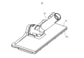
- Fig. 1(a) is a perspective view showing a suction port of the first embodiment
- Fig. 1(b) is a perspective view of the suction port of the first embodiment with a cleaning sheet fixed thereto.
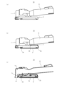
- Fig. 2(a) is a side view of the suction port of the first embodiment
- Fig. 2(b) is a side view of the suction port of the first embodiment with a cleaning sheet fixed thereto.
- Fig. 2(c) is a cross-sectional view of the suction port of the first embodiment.
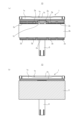
- Fig. 3(a) is a bottom view of the suction port of the first embodiment
- Fig. 3(a) is a bottom view of the suction port of the first embodiment
- FIG. 3(b) is a bottom view of the suction port of the first embodiment with a cleaning sheet fixed thereto.
- Fig. 4 is a cross-sectional view of Fig. 1(a) taken along line A-A.
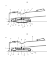
- Fig. 5(a) is a cross-sectional view of the suction port of the first embodiment, and Fig. 5(b) is a cross-sectional view of the suction port of the first embodiment.
- the suction port 10 of the vacuum cleaner of the first embodiment of the present invention has a suction nozzle 1 that sucks in dust on the surface to be cleaned, and a wiper plate 2 that wipes the surface to be cleaned.
- the suction nozzle 1 has a substantially rectangular opening 1a formed on the bottom surface, a suction chamber 1c formed by multiple inner wall surfaces 1b surrounding the opening 1a, and a suction port 1d formed at the top of the suction chamber 1c that connects the opening 1a to the vacuum cleaner body.
- the cleaning sheet 3 can be fixed to the bottom surface 2b of the wiper plate 2 via the attachment/detachment means 2a, and the bottom surface 2b is disposed near the opening 1a of the suction nozzle 1.
- the suction nozzle 1 has a constriction portion 1e formed near approximately the center of the longitudinal direction of the opening 1a, where the distance between the opposing inner wall surfaces 1b, 1b of the suction chamber 1c is narrowed.
- the suction port 10 of the first embodiment employs a brush as the attachment/detachment means 2a, and the brush 2a is formed in a straight line along the longitudinal direction of the upper surface of the wiper plate 2. Brushes 2a are also formed along the longitudinal direction at two locations on the lower surface of the wiper plate 2. The brushes 2a become entangled with the cleaning sheet 3, which is mainly made of nonwoven fabric, thereby fixing the cleaning sheet 3 to the wiper plate 2.
- the wiper plate 2 is composed of a wiper plate body 2c, a first buffer member 2d (e.g., sponge) made of a different soft material, and a second buffer member 2e (e.g., elastomer resin).
- a first buffer member 2d e.g., sponge
- a second buffer member 2e e.g., elastomer resin
- the suction port 10 of the first embodiment has a plate-shaped base that protrudes backward from the bottom of the rotating tube 7, and a spring 5 (see Fig. 5) is provided on the top surface of the base, with a buffer piece 4 at the tip of the spring 5.
- the buffer piece 4 abuts against the connecting tube 6 by the force of the spring 5, and frictional resistance occurs between the connecting tube 6 and the buffer piece 4, preventing the suction nozzle 1 and wiper plate 2 from turning over.
- the same effect can be achieved by forming the spring 5 on the top surface of the wiper plate and having the buffer piece 4 abut against the connecting tube 6.
- frictional resistance occurs when the rotating tube 7 rotates, which assists the user in rotating smoothly.
- the suction port 10 of the first embodiment has a notch 8a for checking the position when installing the cleaning sheet 3 and a protrusion 8b for alignment formed on both sides of the suction port 10 between the suction nozzle 1 and the wiper plate 2.
- the cleaning sheet 3 is formed with approximately the same width as the wiper plate 2, and when the suction port 10 is placed on top of the cleaning sheet 3, the notches 8a, 8a on both sides can be used to check whether the cleaning sheet 3 is attached correctly horizontally.
- the cleaning sheet 3 can be fixed in the appropriate position vertically by attaching it so that the front end of the cleaning sheet 3 matches the alignment protrusions 8b, 8b.
- the cleaning sheet 3 is placed on the surface to be cleaned, and the user can simply place the suction port 10 on it while standing, allowing the cleaning sheet 3 to be attached to the appropriate position of the suction port 10. Therefore, when the suction port 10 is viewed from above, the position of the cleaning sheet 3 can be ascertained, and the position can be fine-tuned without touching the suction port 10 or the cleaning sheet 3.
- a small gap (of the order of a few millimeters) is formed between the upper surface of the wiper plate 2 and the lower surface of the rotating tube 7 or connecting tube 6.
- the rotating tube 7 or connecting tube 6 is designed to bend slightly downward or rotate when the suction port 10 is moved. This allows the rotating tube 7 or connecting tube 6 to press against the wiper plate 2 from above, firmly pressing against approximately the center of the wiper plate 2.
- the flexing or rotation of the rotating tube 7 or the connecting tube 6 can be achieved either by using a flexible material or by providing an axis for rotation.
- the force exerted when the user moves the suction port 10 is transmitted to the suction nozzle 1 through the connecting tube 6 and the rotating tube 7, and is therefore difficult to transmit to the wiper plate 2 located behind the suction nozzle 1, preventing the cleaning effect from being fully achieved. Therefore, by using the above configuration, the approximate center of the wiper plate 2 can be firmly pressed, improving the cleaning effect.
- the bristles 2f of the brush 2a are planted with their longitudinal direction inclined relative to the wiper plate 2. This allows the bristles 2f to penetrate deep into the cleaning sheet 3, which is mainly made of nonwoven fabric, and to be firmly fixed therein by the cleaning action of moving the suction port 10 back and forth.
- the inclination direction of the brushes 2a is such that the brushes 2a on the front side of the wiper plate 2 are inclined backwards, and the brushes 2a on the rear side of the wiper plate 2 are inclined forwards. This prevents them from slipping out, and the cleaning sheet 3 is firmly fixed in place. Note that the brushes 2a on the front side of the wiper plate 2 are inclined forwards, and the brushes 2a on the rear side of the wiper plate 2 are inclined backwards, which also prevents them from slipping out, and this is also included in the present invention.
- the structure will be such that they are less likely to come off due to the force exerted when the suction port 10 moves in the front-rear direction, and this is also included in the present invention. Also, if the direction of the bristles 2f inside the brush 2a is inclined in various ways (when the tips of the bristles 2f point in various directions), the bristles 2f can easily enter the inside of the cleaning sheet 3 and have the effect of preventing them from coming off, so this is also included in the present invention.
- the brush 2a is arranged so as to have an intermittent portion 2g in the width direction of the wiper plate 2. This improves the degree of freedom of the tips of the bristles 2f, allowing the bristles 2f to be inserted deep into the cleaning sheet 3. It is also possible to provide a widthwise groove in the bottom surface 2b of the wiper plate 2 and sequentially insert multiple straight brushes into this groove, allowing the brushes themselves to oscillate with freedom in the groove direction, which is also included in the present invention.
- the suction port 10 of the first embodiment is configured such that, when in use, a space 2h is formed between the bottom surface of the wiper plate body 2c and the top surface of the first buffer member 2d.
- the second buffer member 2e made of elastomer resin has spring properties, and as shown in FIG. 5(b), when the cleaning sheet 3 is fixed, the first buffer member 2d and the second buffer member 2e are recessed inward, eliminating the space 2h.
- the second buffer member 2e protrudes outward, allowing the cleaning sheet 3 to be pressed against the surface to be cleaned, reducing uneven cleaning.
- the first buffer member 2d and the second buffer member 2e are made of different soft materials, and as long as they provide the same inventive effect, they are included in the present invention without being limited to sponge or elastomer resin.
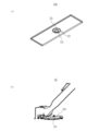
- FIG. 6(a) is a perspective view showing a second cushioning member used in the suction port of the second embodiment
- FIG. 6(b) is a cross-sectional view showing the suction port of the second embodiment.
- the second embodiment of the suction port of a vacuum cleaner according to the present invention will be described below using these figures.
- the second cushioning member 22e used in the suction port 20 of the second embodiment has a cone-shaped protrusion 22i formed in the center, and the outer circumferential surface of the protrusion 22i has multiple ribs 22j formed thereon that extend in a direction angled relative to the radial direction.
- the multiple ribs 22j When the second buffer member 22e is pressed against the surface to be cleaned, the multiple ribs 22j generate a biasing force, causing the central cone-shaped protrusion 22i to push back against the wiper plate body, allowing the cleaning sheet 3 to be pressed firmly against the surface to be cleaned, reducing uneven cleaning.
- FIG. 7 is a perspective view showing the suction port of the third embodiment
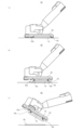
- FIGS. 8(a) to (c) are side views showing the suction port of the third embodiment in use.
- the third embodiment of the suction port of the vacuum cleaner according to the present invention will be described below using these figures.
- a brush 32a which is a detachable means, is formed on the rear side of the wiper plate 32.
- the brush 32a on that side is attached so as to match the rear end of the cleaning sheet 33 placed on the surface to be cleaned (FIG. 8(a) state), and the bottom surface of the wiper plate 32 is placed on the cleaning sheet 33 in this state (FIG.
- a brush which is a detachable means, can be provided on the front side as well as the rear side, so that the cleaning sheet can be attached from the front side, and this is also included in the present invention.
- the connecting pipe 36 can be tilted in either the forward or backward direction from vertically above the wiper plate 32. This allows the cleaning sheet 33 formed on the rear side of the wiper plate 32 to clean the wall surface, improving the performance of the suction port 30 when in use.
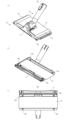
- FIG. 9(a) is a bottom view of the suction port of the fourth embodiment
- FIG. 9(b) is a side view of the suction port of the fourth embodiment
- FIG. 9(c) is a perspective view of the suction port of the fourth embodiment.
- the fourth embodiment of the suction port of the vacuum cleaner according to the present invention will be described below using these figures.
- the suction port 40 of the fourth embodiment is located behind the suction nozzle 41 and has a blade 9 between it and the brush 42a on the front side of the bottom surface of the wiper plate 42. This blade 9 is intended to obtain the effect of blocking dirt and sweeping up the dirt, and the cleaning sheet 43 is fixed to the wiper plate 42 by hooking it onto the tip of the blade 9.
- the suction port 40 of the fourth embodiment is able to reduce frictional resistance (sliding resistance) without damaging the surface to be cleaned with the blade 9 by interposing the cleaning sheet 43 between it and the blade 9.
- the blade 9 protrudes below the suction port 40, and since the blade 9 itself is flexible (does not easily bend), a part of the cleaning sheet 43 can be pressed firmly against the surface to be cleaned, improving the cleaning effect.
- FIG. 10(a) is a perspective view showing the suction port of the fifth embodiment
- FIG. 10(b) is a perspective view showing the suction port of the fifth embodiment with the wiper plate removed
- FIG. 10(c) is a perspective view showing the wiper plate used in the suction port of the fifth embodiment
- FIG. 11(a) is a perspective view showing the operating handle used in the wiper plate of the fifth embodiment
- FIG. 11(b) is a perspective view showing the operating handle attached to the wiper plate of the fifth embodiment.
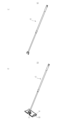
- the suction port 50 of the fifth embodiment is configured so that the suction nozzle 51 at the front and the wiper plate 52 at the rear can be separated using the attachment means 11. This allows it to be used as a vacuum cleaner with only the suction nozzle 51, as shown in FIG. 10(b). Also, the attachment means 11 can be used to attach the operating handle 12 shown in FIG. 11(a), allowing it to be used as a floor wiper 13, as shown in FIG. 11(b).
- the suction port 50 of the fifth embodiment is configured such that a notch 14 is formed on one or both of the left and right sides of the wiper plate 52. This allows the cleaning sheet 53 to be fixed to the bottom surface of the wiper plate 52 so that it protrudes outward from the notch 14. Therefore, when removing the cleaning sheet 53, the cleaning sheet 53 can be easily removed by stepping on the part of the cleaning sheet 53 protruding from the notch 14 with the foot.
- FIGS 12(a)-(c) are side views showing the sixth embodiment of the suction port in use.
- the sixth embodiment of the suction port of the vacuum cleaner according to the present invention will be described below using these figures.
- the sixth embodiment of the suction port 60 of the sixth embodiment is provided with a knock cam mechanism 16 (a mechanism similar to that used to insert and remove the lead of a ballpoint pen) having spring members 16a, 16b between the underside of the wiper plate 62 and the upper surface of the buffer member 15, and the buffer member 15 can be transformed into a state in which it protrudes significantly from the bottom surface of the wiper plate 62 (the state in Figure 12(b)) and a state in which it protrudes slightly (the state in Figure 12(a)), and can be used as a means for attaching and detaching the cleaning sheet 63.
- a knock cam mechanism 16 a mechanism similar to that used to insert and remove the lead of a ballpoint pen
- the procedure for attaching and detaching the cleaning sheet 63 at the suction port 60 of the sixth embodiment is as follows. First, the buffer member 15 is placed in a state where it protrudes significantly from the bottom surface of the wiper plate 62. Next, when the buffer member 15 is pressed against the cleaning sheet 63 placed on the surface to be cleaned, the buffer member 15 retracts into the inside of the wiper plate 62 and the brush 62a, which is the attachment and detachment means on the bottom surface of the wiper plate 62, and the cleaning sheet 63 are fixed to it.
- a buffer member may be protruded when a button provided on the top surface of the wiper plate is pressed, and the buffer member may be pressed against the surface to be cleaned, causing the buffer member to return to its initial position. This is also included in the present invention.
- FIG. 13(a) is a perspective view of the suction port of the seventh embodiment with a cleaning sheet fixed thereto
- FIG. 13(b) is a perspective view of the suction port of the seventh embodiment as viewed from the bottom side
- FIG. 13(c) is a bottom view of the suction port of the seventh embodiment.
- FIG. 14 is a cross-sectional view taken along line B-B of FIG. 13(a).
- intake passages 17a, 17b are formed from the vicinity of both longitudinal ends of the suction nozzle 71 toward the vicinity of both ends (both left and right sides) of the wiper plate 72, and a portion of these intake passages 17a, 17b are configured to communicate with intake holes 18a, 18b, 18c, 18d formed in the bottom surface of the wiper plate 72.
- the intake passages 17a, 17b may be formed at any position within the suction nozzle 71, and the intake holes 18a, 18b, 18c, 18d may be formed at predetermined positions on the wiper plate 72 that face the four corners of the cleaning sheet 73.
- a brush configuration which is the attachment/detachment means shown in the other embodiments, may be added, in which case a synergistic effect will result in a more secure fixation of the cleaning sheet 73 to the wiper plate 72.
- FIG. 15(a) is a perspective view showing the suction port of the eighth embodiment
- FIG. 15(b) is a bottom view showing the suction port of the eighth embodiment
- FIG. 15(c) is a side view of the suction port of the eighth embodiment with a cleaning sheet fixed.
- the eighth embodiment of the suction port of the vacuum cleaner according to the present invention will be described below using these figures.
- the suction port 80 of the eighth embodiment is equipped with a rotating brush 19a, and brushes 82a, 82a, which are attachment and detachment means, are arranged on the suction port body 19b located behind the rotating brush 19a.
- the cleaning sheet 83 can be attached so as to cover the entire bottom surface of the suction port body 19b behind the rotating brush 19a, as shown in FIG. 15(c). It is also possible to form the suction port 80 of the eighth embodiment by attaching brushes 82a, 82a, each of which has an adhesive surface formed on one side, to the bottom surface of a typical suction port body 19b that is commercially available.
- the suction port of the vacuum cleaner according to the present invention is used as a cleaning tool equipped with a wiper plate for wiping the surface to be cleaned.
Landscapes
- Engineering & Computer Science (AREA)
- Mechanical Engineering (AREA)
- Nozzles For Electric Vacuum Cleaners (AREA)
Abstract
【課題】 清掃シートへの着脱が容易であり、作業性を向上させることができると共に、大きな塵埃のみならず、被清掃面に付着した小さな塵埃も除去することができる電気掃除機の吸込口を提供する。 【解決手段】 電気掃除機の吸込口10は、被清掃面上の塵埃を吸引する吸入ノズル1と、被清掃面上の拭き清掃をするワイパープレート2と、を有しており、吸入ノズル1は、底面に形成される略矩形状の開口1aと、該開口1aを囲う内壁面1bにより形成される略箱形状の吸引室1cと、該吸引室1cの上部に形成され、開口1aと電気掃除機本体とを連通させる吸引口1dとを有している。
Description
本発明は、被清掃面上の拭き清掃を行うワイパープレートを備えたに電気掃除機の吸込口に関するものである。
従来から柄棒の先端に連結された拭布取付部材に、紙や布帛等からなる拭布を交換可能に取り付けたモップの発明が知られている(特許文献1)。
特許文献1に記載のモップは、払掃用の拭布と、該拭布を交換可能に装着するための扁平で細長い拭布取付部材と、該拭布取付部材に連結された操作用の柄棒とからなっていて、 上記拭布取付部材は、合成ゴムや合成樹脂のような柔軟性を持った弾性部材によって長方形をなす薄肉の平板状に形成され、四隅に近い位置に、巻き付けた拭布の端部を係止させるための係止手段が係止され、上面の中央部に、連結手段を介して上記柄棒が連結される構成としている。
しかしながら上記特許文献1に記載のモップの拭布は、四隅に近い位置に形成された係止手段に係止させる手間を必要とするものであると共に、係止手段が切り込み孔で形成されている場合には、拭布がちぎれて係止手段に残存する場合があるため、取り除く作業を必要としていた。また、大きな塵埃は拭布では拭き取れないため、電気掃除機で同じ個所の清掃を再度行わなければならないという課題を有するものであった。
本発明は、前記従来の課題を解決するものであり、清掃シートへの着脱が容易であり、作業性を向上させることができると共に、大きな塵埃のみならず、被清掃面に付着した小さな塵埃も除去することができる電気掃除機の吸込口を提供することを目的とする。
前記従来の課題を解決するために、請求項1の発明は、被清掃面上の塵埃を吸引する吸入ノズルと、被清掃面上の拭き清掃をするワイパープレートと、を有する電気掃除機の吸込口において、前記吸入ノズルは、底面に形成される略矩形状の開口と、該開口を囲う複数の内壁面により形成される吸引室と、該吸引室の上部に形成され、前記開口と電気掃除機本体とを連通させる吸引口とを有し、前記ワイパープレートは、着脱手段を介して該ワイパープレートの底面に清掃シートを固定できると共に、該底面は前記吸引ノズルの開口の近傍に配置されているものであって、前記吸引ノズルは、前記開口の長手方向の略中央部近傍において、前記吸引室の対向する内壁面の距離が狭まる絞り部が形成されていることを特徴としている。
請求項1の発明では、ワイパープレートが着脱手段を介して底面に清掃シートを固定できるので、作業性を向上させることができる。また、開口の長手方向の略中央部近傍において、吸引室の対向する内壁面の距離が狭まる絞り部が形成された吸引ノズルを使用することによって、最も塵埃が集中する開口の略中央部における吸引力を向上させると共に、全体として所望の吸引力を維持しつつ、コンパクトな形状にすることができ、大きな塵埃のみならず、被清掃面に付着した小さな塵埃も除去することができる電気掃除機の吸込口とすることができる。
請求項2の発明は、請求項1の発明において、吸引室は、開口面から上面までの高さが、開口の長手方向の略中央部よりも端部の方が低いことを特徴としている。これにより、吸引ノズルは、開口の端部側においても所定の吸引力を維持することができるため、清掃効率を向上させることができる。
請求項3の発明は、請求項1又は2の発明において、吸引室は、開口の短手方向を面とする断面において、開口の長手方向の略中央部よりも端部の断面積が小であることを特徴としている。これにより、吸引ノズルは、開口の端部側においても所定の吸引力を維持することができるため、清掃効率を向上させることができる。
請求項1の発明は、ワイパープレートに清掃シートを固定する作業性を向上させることができると共に、最も塵埃が集中する開口の略中央部における吸引力を向上させ、全体として所望の吸引力を維持しつつ、コンパクトな形状にすることができる。また、請求項2及び3の発明は、吸引ノズルの開口の端部側においても所定の吸引力を維持することができるため、清掃効率を向上させることができる。
以下、本発明の実施形態について、図面を参照しながら説明する。尚、この実施の形態によって本発明が限定されるものではない。図1(a)は、第1実施形態の吸込口を示す斜視図であり、図1(b)は、第1実施形態の吸込口であって、清掃シートを固定した状態の斜視図である。図2(a)は、第1実施形態の吸込口を示す側面図であり、図2(b)は、第1実施形態の吸込口であって、清掃シートを固定した状態の側面図である。また、図2(c)は、第1実施形態の吸込口を示す断面図である。図3(a)は、第1実施形態の吸込口を示す底面図であり、図3(b)は、第1実施形態の吸込口であって、清掃シートを固定した状態の底面図である。図4は、図1(a)のA-A断面図である。図5(a)は、第1実施形態の吸込口を示す断面図であり、図5(b)は、第1実施形態の吸込口を示す断面図である。これらの図を用いて本発明に係る電気掃除機の吸込口の第1実施形態について以下に説明する。
本発明に係る第1実施形態の電気掃除機の吸込口10は、被清掃面上の塵埃を吸引する吸入ノズル1と、被清掃面上の拭き清掃をするワイパープレート2と、を有しており、吸入ノズル1は、底面に形成される略矩形状の開口1aと、該開口1aを囲う複数の内壁面1bにより形成される吸引室1cと、該吸引室1cの上部に形成され、開口1aと電気掃除機本体とを連通させる吸引口1dとを有している。
ワイパープレート2は、着脱手段2aを介して該ワイパープレート2の底面2bに清掃シート3を固定できると共に、底面2bは吸引ノズル1の開口1aの近傍に配置されているものであって、吸引ノズル1は、開口1aの長手方向の略中央部近傍において、吸引室1cの対向する内壁面1b、1bの距離が狭まる絞り部1eが形成されている。
第1実施形態の吸込口10は、着脱手段2aとしてブラシを採用しており、ブラシ2aがワイパープレート2の上面の長手方向に沿って直線状に形成されている。また、ワイパープレート2の下面の2か所にも長手方向に沿ってブラシ2aが形成されている。このブラシ2aが主に不織布で形成された清掃シート3に絡みつくことによって、ワイパープレート2に清掃シート3が固定される構成としている。
また、ワイパープレート2は、ワイパープレート本体2cと、異なる軟質部材で形成された第1緩衝部材2d(例えば、スポンジ)と、第2緩衝部材2e(例えば、エラストマー樹脂)とで構成されている。
第1実施形態の吸込口10は、図5(a)及び(b)に示すように、回動管7の下部には後方に突出する板状の基台が設けられており、基台の上面にはバネ5(図5参照)及びバネ5の先端に緩衝片4が設けれている。緩衝片4は、バネ5の付勢力を受けて接続管6と当接するものであり、接続管6との間に摩擦抵抗が生じることから、吸引ノズル1及びワイパープレート2が反転するのを防ぐことができる。尚、バネ5をワイパープレートの上面に形成し、緩衝片4を接続管6に当接させても同様の効果を生じさせるものである。また、緩衝片4を接続管6に変えて回動管7に当接させた場合は、回動管7が回動する時に摩擦抵抗が生じるため、使用者のスムーズな回動をアシストすることができる。
第1実施形態の吸込口10は、図1(a)及び(b)に示すように、吸引ノズル1とワイパープレート2との間に、清掃シート3を設置する時の位置確認用の切欠き8aと、位置合わせ用の突起8bが、吸込口10の両側部に各々形成されている。
清掃シート3は、ワイパープレート2の横幅と略同じ幅で形成されており、清掃シート3の上から吸込口10を載せると、両側部の切欠き8a、8aから清掃シート3の横位置が正確に貼り合わされているかを確認することができる。また、清掃シート3の縦位置については、清掃シート3の前方端部と位置合わせ用の突起8b、8bとが合うように貼り合わせることで、清掃シート3を適切な位置に固定することができる。
これにより、清掃シート3を被清掃面に置き、使用者が立った状態で、吸込口10を載せるだけで清掃シート3を吸込口10の適切な位置に貼り合わせることができる。したがって、吸込口10を上方から見た際に、清掃シート3の位置が把握できると共に、吸込口10や清掃シート3を触らずに位置の微調整を図ることができる。
第1実施形態の吸込口10は、図2(c)に示すように、収納時はワイパープレート2の上面と、回動管7又は接続管6の下面との間に僅かな隙間(数ミリ程度)が形成されている。使用時は、吸込口10を動かす際、に回動管7又は接続管6が僅かに下方に撓む又は、回動できる構造としている。これにより、回動管7又は接続管6がワイパープレート2を上方から押さえることとなり、ワイパープレート2の略中央をしっかり押圧することができる。
回動管7又は接続管6の撓み又は回動は、撓みやすい材質にする場合と、軸を設けて回動させる場合の両方を採用することができる。また、回動管7又は接続管6と当接するワイパープレート2の上面は少し窪みを設けることで、回動管7や接続管6と点接触するのではなく、面接触させて抑える力を十分に且つ安全に伝える構造とすることができる。
使用者が吸込口10を動かす際の力は、接続管6及び回動管7を通じて吸引ノズル1に伝わるため、吸引ノズル1の後方に位置するワイパープレート2には伝わりづらく清掃効果を十分に発揮できない。そこで上記構成とすることで、ワイパープレート2の略中央部をしっかり押圧することができ清掃効果を向上させることができる。
第1実施形態の吸込口10は、図2(a)~(c)に示すように、ブラシ2aの毛材2fの長手方向がワイパープレート2に対して傾斜して植毛されている。これにより、吸込口10を前後に動かす清掃動作によって、毛材2fを主に不織布で形成された清掃シート3の内部奥深くまで侵入させると共に強固に固定することができる。
ブラシ2aの傾斜方向は、ワイパープレート2の前方側のブラシ2aは後方に向かい傾斜させ、ワイパープレート2の後方側のブラシ2aは前方に向かい傾斜させる構成としている。これにより、互いに抜け止めとなり清掃シート3の固定が強固になる。尚、ワイパープレート2の前方側のブラシ2aを前方に向かい傾斜させ、ワイパープレート2の後方側のブラシ2aを後方に傾斜させた場合も抜け止めになるので、これも本発明に含まれる。
また、ワイパープレート2の前方側のブラシ2aと後方側のブラシ2aの傾斜方向をそれぞれ左右方向とした場合も、吸込口10の前後方向への移動時の力では外れにくい構造となるので、これも本発明に含まれる。また、ブラシ2aの内部で毛材2fの方向を様々に傾斜させた場合(様々な方向に毛材2fの先端が向いている場合)については、毛材2fが清掃シート3内部に入りやすいと共に抜け止めの効果があるのでこれも本発明に含まれる。さらに、ワイパープレート2の上面に形成されたブラシ2aについては、毛材2fを前方側に傾斜させることで、清掃シート3を後方側から巻きまわして底面2bに固定する際の抜け止めとなるので、これも本発明に含まれる。
第1実施形態の吸込口10は、図3(a)に示すように、ブラシ2aを、ワイパープレート2の幅方向に、間欠部2gを有するようにして配置している。これにより、毛材2fの先端の自由度を向上させて、毛材2fを清掃シート3の奥まで挿入させることができる。尚、ワイパープレート2の底面2bに幅方向の溝を設けて、この溝に複数の直線ブラシを順次挿入して、ブラシ自体が溝方向に自由度を持って揺動する構成とすることも可能であり、これも本発明に含まれる。
第1実施形態の吸込口10は、図5(a)に示すように、使用時に、ワイパープレート本体2cの下面と第1緩衝部材2dの上面との間に空間部2hが形成される構成としている。これは、エラストマー樹脂で形成された第2緩衝部材2eがバネ性を有していることからであり、図5(b)に示すように、清掃シート3の固定時には、第1緩衝部材2dと第2緩衝部材2eが内方に凹むことによって空間部2hは消滅する。これにより、使用時には、第2緩衝部材2eが外方に突出することから、清掃シート3を被清掃面に押し当てることができ、清掃ムラを減少させることができる。尚、第1緩衝部材2dと第2緩衝部材2eとは異なる軟質部材で形成されており、同様の発明の効果を奏するものであれば、スポンジやエラストマー樹脂に限定されることなく本発明に含まれる。
図6(a)は、第2実施形態の吸込口に使用する第2緩衝部材を示す斜視図であり、図6(b)は、第2実施形態の吸込口を示す断面図である。これらの図を用いて本発明に係る電気掃除機の吸込口の第2実施形態について以下に説明する。第2実施形態の吸込口20に使用する第2緩衝部材22eは、中央にすり鉢状の突部22iが形成されており、突部22iの外周面には径方向に対して角度を有する方向に延出する複数のリブ22jが形成されている。
そして、第2緩衝部材22eを被清掃面に押し当てた際は、複数のリブ22jが付勢力を発生させることから、中央にすり鉢状の突部22iがワイパープレート本体を押し返し、清掃シート3を被清掃面に強く押し当てることができ、清掃ムラを減少させることができる。
図7は、第3実施形態の吸込口を示す斜視図であり、図8(a)~(c)は、第3実施形態の吸込口の使用状態を示す側面図である。これらの図を用いて本発明に係る電気掃除機の吸込口の第3実施形態について以下に説明する。第3実施形態の吸込口30は、ワイパープレート32の後方側面に着脱手段であるブラシ32aが形成されており、当該側面のブラシ32aを、被清掃面に置いた清掃シート33の後方端部に合わせるように貼り合わせて(図8(a)の状態)、そのまま清掃シート33の上にワイパープレート32の底面を置くことで(図8(b)の状態)、清掃シート33がずれることなくワイパープレート32の適切な位置に、清掃シート33を固定させることができる。尚、後方側面だけでなく前方側面にも着脱手段であるブラシを設けて、前方側から清掃シートを装着する構成とすることもでき、これも本発明に含まれる。
また、図8(c)に示すように、接続管36はワイパープレート32の垂直上方から前後のどちらの方向にも傾斜させることが可能な構成としている。これにより、ワイパープレート32の後方側面に形成した清掃シート33で壁面の清掃を行うことができ、吸込口30使用時の性能を向上させることができる。
図9(a)は、第4実施形態の吸込口を示す底面図であり、図9(b)は、第4実施形態の吸込口を示す側面図図9(c)は、第4実施形態の吸込口を示す斜視図である。これらの図を用いて本発明に係る電気掃除機の吸込口の第4実施形態について以下に説明する。第4実施形態の吸込口40は、吸引ノズル41の後方であって、ワイパープレート42の底面の前方側のブラシ42aとの間にブレード9を有する構成としている。このブレード9は、ゴミを堰き止める効果及び、ゴミを掃く効果を得るためのものであり、清掃シート43は、ブレード9の先端に引っ掛けるようにしてワイパープレート42に固定している。
第4実施形態の吸込口40は、清掃シート43がブレード9との間に介在することで、被清掃面をブレード9により傷つけることなく、摩擦抵抗(摺動抵抗)を抑えることができる。また、ブレード9は吸込口40の下方に突出しており、ブレード9自体に腰があるため(折れ曲がりにくいため)、清掃シート43の一部を被清掃面に強く押し当てて清掃効果を向上させることができる。
図10(a)は、第5実施形態の吸込口を示す斜視図であり、図10(b)は、第5実施形態の吸込口においてワイパープレートを取り外した状態を示す斜視図であり、図10(c)は、第5実施形態の吸込口に使用するワイパープレートを示す斜視図である。また、図11(a)は、第5実施形態のワイパープレートに使用する操作用の柄を示す斜視図であり、図11(b)は、第5実施形態のワイパープレートに操作用の柄を取り付けた状態を示す斜視図である。これらの図を用いて本発明に係る電気掃除機の吸込口の第5実施形態について以下に説明する。
第5実施形態の吸込口50は、前方の吸引ノズル51と後方のワイパープレート52とを取付手段11を用いて分離可能な構成としている。これにより、図10(b)に示すように、吸引ノズル51のみの電気掃除機として使用することができる。また、取付手段11を用いて図11(a)に示す操作用の柄12を取り付けることができ、図11(b)に示すように、フローリングワイパー13として使用することができる。
第5実施形態の吸込口50は、ワイパープレート52の左右の一方又は両方に切欠き部14が形成された構成としている。これにより、清掃シート53は、切欠き部14から外側にはみ出るようにワイパープレート52の底面に固定することができるので、清掃シート53を取り外す際は、切欠き部14からはみ出た部分の清掃シート53を足で踏みつけることによって、清掃シート53を容易に取り外すことができる。
図12(a)~(c)は、第6実施形態の吸込口の使用状態を示す側面図である。これらの図を用いて本発明に係る電気掃除機の吸込口の第6実施形態について以下に説明する。第6実施形態の吸込口60は、ワイパープレート62の下面と緩衝部材15の上面との間にバネ部材16a、16bを有するノックカム機構16(ボールペンの芯の出し入れと同様の機構)が設けられており、緩衝部材15がワイパープレート62の底面から大きく突出した状態(図12(b)の状態)と、多少突出した状態(図12(a)の状態)とに変形することができ、清掃シート63の着脱手段とすることができる。
第6実施形態の吸込口60における清掃シート63の着脱の手順は、以下のとおりである。第1に、緩衝部材15がワイパープレート62の底面から大きく突出した状態にする。次に、被清掃面に置いた清掃シート63の上から緩衝部材15を押し付けると、緩衝部材15がワイパープレート62の内部側に引っ込む状態になると共に、ワイパープレート62の底面の着脱手段であるブラシ62aと清掃シート63とを固定する。この状態で被清掃面の清掃を行い、清掃が終わり、清掃シート63を取り外す又は交換する際には、再び清掃シート63を被清掃面に設置した状態で、緩衝部材15を被清掃面側に押し付けると、ノックカム機構16により緩衝部材15が大きく突出した状態となるため、図12(c)に示すように、ブラシ62aに固定されていた清掃シート63を引き剥がして取り外すことができる。
尚、ノックカム機構15に替えて、ワイパープレートの上面に設けられたボタンを押した際に緩衝部材が突出し、該緩衝部材を被清掃面に押し付けることで緩衝部材が初期位置に戻る構成としてもよく、これも本発明に含まれる。
図13(a)は、第7実施形態の吸込口であって、清掃シートを固定した状態の斜視図であり、図13(b)は、第7実施形態の吸込口を底面側から視た斜視図であり、図13(c)は、第7実施形態の吸込口を示す底面図である。また、図14は、図13(a)のB-B断面図である。これらの図を用いて本発明に係る電気掃除機の吸込口の第7実施形態について以下に説明する。第7実施形態の吸込口70は、吸引ノズル71の長手方向の両端部近傍からワイパープレート72の両端部近傍(左右の両辺)に向かい吸気通路17a、17bが形成されており、この吸気通路17a、17bの一部がワイパープレート72の底面に形成された吸気孔18a、18b、18c、18dと連通する構成としている。これにより、電気掃除機を稼動させると吸気孔18a、18b、18c、18dにも吸引力が発生することとなり清掃シート73を吸着させることができる。
尚、吸気通路17a、17bの構成は、吸引ノズル71内のどの位置から形成していてもよく、吸気孔18a、18b、18c、18dは、清掃シート73の四隅に対向するワイパープレート72の所定の位置に形成されていればよいものである。また、他の実施形態で示した着脱手段であるブラシの構成を追加してもよく、その場合には、相乗効果でより強固にワイパープレート72に清掃シート73を固定することができる。
図15(a)は、第8実施形態の吸込口を示す斜視図であり、図15(b)は、第8実施形態の吸込口を示す底面図であり、図15(c)は、第8実施形態の吸込口であって、清掃シートを固定した状態の側面図である。これらの図を用いて本発明に係る電気掃除機の吸込口の第8実施形態について以下に説明する。第8実施形態の吸込口80は、回転ブラシ19aを備えており、この回転ブラシ19aの後方に位置する吸込口本体19bに着脱手段であるブラシ82a、82aを配置した構成としている。
これにより、清掃シート83は、図15(c)に示すように、回転ブラシ19a後方の吸込口本体19bの底面全体を覆うように取り付けることができる。また、市販されている一般的な吸込口本体19bの底面に、一方の面に接着面が形成されているブラシ82a、82aを貼り付けることによって第8実施形態の吸込口80を構成することも可能である。
本発明に係る電気掃除機の吸込口は、被清掃面上の拭き清掃を行うワイパープレートを備えた清掃道具として利用される。
1、41、51、71 吸引ノズル
1a 開口
1b 内壁面
1c 吸引室
1d 吸引口
1e 絞り部
2、32、42、52、62、72 ワイパープレート
2a、32a、42a、62a、82a 着脱手段(ブラシ)
2b 底面
2c ワイパープレート本体
2d 第1緩衝部材
2e 第2緩衝部材
2f 毛材
2g 間欠部
2h 空間部
3、33、43、53、63、73、83 清掃シート
4 緩衝片
5 バネ
6、36 接続管
7 回動管
8a 切欠き
8b 突起
9 ブレード
10、20、30、40、50、60、70、80 電気掃除機の吸込口
11 取付手段
12 操作用の柄
13 フローリングワイパー
14 切欠き部
15 緩衝部材
16 ノックカム機構
16a、16b バネ部材
17a、17b 吸気通路
18a、18b、18c、18d 吸気孔
19a 回転ブラシ
19b 吸込口本体
22i 突部
22j リブ
22k 平面部
1a 開口
1b 内壁面
1c 吸引室
1d 吸引口
1e 絞り部
2、32、42、52、62、72 ワイパープレート
2a、32a、42a、62a、82a 着脱手段(ブラシ)
2b 底面
2c ワイパープレート本体
2d 第1緩衝部材
2e 第2緩衝部材
2f 毛材
2g 間欠部
2h 空間部
3、33、43、53、63、73、83 清掃シート
4 緩衝片
5 バネ
6、36 接続管
7 回動管
8a 切欠き
8b 突起
9 ブレード
10、20、30、40、50、60、70、80 電気掃除機の吸込口
11 取付手段
12 操作用の柄
13 フローリングワイパー
14 切欠き部
15 緩衝部材
16 ノックカム機構
16a、16b バネ部材
17a、17b 吸気通路
18a、18b、18c、18d 吸気孔
19a 回転ブラシ
19b 吸込口本体
22i 突部
22j リブ
22k 平面部
Claims (3)
- 被清掃面上の塵埃を吸引する吸入ノズルと、被清掃面上の拭き清掃をするワイパープレートと、を有する電気掃除機の吸込口において
前記吸入ノズルは、底面に形成される略矩形状の開口と、該開口を囲う複数の内壁面により形成される吸引室と、該吸引室の上部に形成され、前記開口と電気掃除機本体とを連通させる吸引口とを有し、
前記ワイパープレートは、着脱手段を介して該ワイパープレートの底面に清掃シートを固定できると共に、該底面は前記吸引ノズルの開口の近傍に配置されているものであって、
前記吸引ノズルは、前記開口の長手方向の略中央部近傍において、前記吸引室の対向する内壁面の距離が狭まる絞り部が形成されている電気掃除機の吸込口 - 吸引室は、開口面から上面までの高さが、開口の長手方向の略中央部よりも端部の方が低いことを特徴とする請求項1に記載の電気掃除機の吸込口
- 吸引室は、開口の短手方向を面とする断面において、開口の長手方向の略中央部よりも端部の断面積が小であることを特徴とする請求項1又は2に記載の電気掃除機の吸込口
Priority Applications (1)
| Application Number | Priority Date | Filing Date | Title |
|---|---|---|---|
| CN202480054931.1A CN121889072A (zh) | 2023-02-17 | 2024-06-28 | 电动吸尘器的吸入口 |
Applications Claiming Priority (3)
| Application Number | Priority Date | Filing Date | Title |
|---|---|---|---|
| JP2023082071 | 2023-05-18 | ||
| JP2023108422A JP2024166001A (ja) | 2023-05-18 | 2023-06-30 | 電気掃除機の吸込口 |
| JP2023-108422 | 2023-06-30 |
Publications (1)
| Publication Number | Publication Date |
|---|---|
| WO2025005275A1 true WO2025005275A1 (ja) | 2025-01-02 |
Family
ID=93608410
Family Applications (1)
| Application Number | Title | Priority Date | Filing Date |
|---|---|---|---|
| PCT/JP2024/023621 Ceased WO2025005275A1 (ja) | 2023-02-17 | 2024-06-28 | 電気掃除機の吸込口 |
Country Status (2)
| Country | Link |
|---|---|
| JP (1) | JP2024166001A (ja) |
| WO (1) | WO2025005275A1 (ja) |
Citations (4)
| Publication number | Priority date | Publication date | Assignee | Title |
|---|---|---|---|---|
| JPH07327877A (ja) * | 1994-06-02 | 1995-12-19 | Matsushita Electric Ind Co Ltd | 吸水用吸込具 |
| JP2001340270A (ja) * | 2000-06-02 | 2001-12-11 | Kyowa Giken:Kk | 電気掃除機用ワイパー付き吸込口装置 |
| JP2005000554A (ja) * | 2003-06-13 | 2005-01-06 | Twinbird Corp | 電気掃除機 |
| EP2633792A2 (en) * | 2012-02-29 | 2013-09-04 | Nilfisk-Advance A/S | A nozzle for cleaning devices |
-
2023
- 2023-06-30 JP JP2023108422A patent/JP2024166001A/ja active Pending
-
2024
- 2024-06-28 WO PCT/JP2024/023621 patent/WO2025005275A1/ja not_active Ceased
Patent Citations (4)
| Publication number | Priority date | Publication date | Assignee | Title |
|---|---|---|---|---|
| JPH07327877A (ja) * | 1994-06-02 | 1995-12-19 | Matsushita Electric Ind Co Ltd | 吸水用吸込具 |
| JP2001340270A (ja) * | 2000-06-02 | 2001-12-11 | Kyowa Giken:Kk | 電気掃除機用ワイパー付き吸込口装置 |
| JP2005000554A (ja) * | 2003-06-13 | 2005-01-06 | Twinbird Corp | 電気掃除機 |
| EP2633792A2 (en) * | 2012-02-29 | 2013-09-04 | Nilfisk-Advance A/S | A nozzle for cleaning devices |
Also Published As
| Publication number | Publication date |
|---|---|
| JP2024166001A (ja) | 2024-11-28 |
Similar Documents
| Publication | Publication Date | Title |
|---|---|---|
| CN101999863B (zh) | 具有可拆卸刷子的真空吸尘器附件工具 | |
| EP2311357A1 (en) | Suction head for a vacuum cleaner | |
| JP2005000643A (ja) | タービンブラシ | |
| GB2504674A (en) | Vacuum appliance floor tool clamping arrangement | |
| GB2504676A (en) | Vacuum appliance floor tool with conduit access arrangement | |
| US8196258B2 (en) | Brush assembly and vacuum cleaner having the same | |
| WO2025005275A1 (ja) | 電気掃除機の吸込口 | |
| EP3284380B1 (en) | Vacuum cleaner head | |
| US20030145425A1 (en) | Multi-function vacuum cleaner accessory | |
| CN121889072A (zh) | 电动吸尘器的吸入口 | |
| JP4363995B2 (ja) | 吸込口体および掃除装置 | |
| US20090044359A1 (en) | Suction brush having hair removal unit for vacuum cleaner | |
| JP2009061209A (ja) | 吸込具及び電気掃除機 | |
| CN209733848U (zh) | 吸嘴及吸尘器 | |
| JP2007021057A5 (ja) | ||
| CN209285363U (zh) | 电动吸尘器的吸尘口组件 | |
| JPH1052386A (ja) | 払掃機能を備えた真空掃除機用吸込み具 | |
| JP3878598B2 (ja) | 電気掃除機 | |
| JP2001340270A (ja) | 電気掃除機用ワイパー付き吸込口装置 | |
| JP3241871U (ja) | 掃除機 | |
| JPS6038444Y2 (ja) | 電気掃除機の吸込具 | |
| JP2007021056A (ja) | 吸込具及びそれを用いた電気掃除機 | |
| JP2025084250A (ja) | 吸込口体及び電気掃除機 | |
| JP2025084248A (ja) | 吸込口体及び電気掃除機 | |
| JP2004337638A (ja) | 電気掃除機用吸込具とそれを用いた電気掃除機 |
Legal Events
| Date | Code | Title | Description |
|---|---|---|---|
| 121 | Ep: the epo has been informed by wipo that ep was designated in this application |
Ref document number: 24832132 Country of ref document: EP Kind code of ref document: A1 |
|
| NENP | Non-entry into the national phase |
Ref country code: DE |