WO2025005270A1 - イントラ予測装置、符号化装置、復号装置、及びプログラム - Google Patents
イントラ予測装置、符号化装置、復号装置、及びプログラム Download PDFInfo
- Publication number
- WO2025005270A1 WO2025005270A1 PCT/JP2024/023601 JP2024023601W WO2025005270A1 WO 2025005270 A1 WO2025005270 A1 WO 2025005270A1 JP 2024023601 W JP2024023601 W JP 2024023601W WO 2025005270 A1 WO2025005270 A1 WO 2025005270A1
- Authority
- WO
- WIPO (PCT)
- Prior art keywords
- intra prediction
- prediction
- region
- cost
- unit
- Prior art date
- Legal status (The legal status is an assumption and is not a legal conclusion. Google has not performed a legal analysis and makes no representation as to the accuracy of the status listed.)
- Ceased
Links
Images



Classifications
-
- H—ELECTRICITY
- H04—ELECTRIC COMMUNICATION TECHNIQUE
- H04N—PICTORIAL COMMUNICATION, e.g. TELEVISION
- H04N19/00—Methods or arrangements for coding, decoding, compressing or decompressing digital video signals
- H04N19/10—Methods or arrangements for coding, decoding, compressing or decompressing digital video signals using adaptive coding
- H04N19/102—Methods or arrangements for coding, decoding, compressing or decompressing digital video signals using adaptive coding characterised by the element, parameter or selection affected or controlled by the adaptive coding
- H04N19/103—Selection of coding mode or of prediction mode
- H04N19/11—Selection of coding mode or of prediction mode among a plurality of spatial predictive coding modes
-
- H—ELECTRICITY
- H04—ELECTRIC COMMUNICATION TECHNIQUE
- H04N—PICTORIAL COMMUNICATION, e.g. TELEVISION
- H04N19/00—Methods or arrangements for coding, decoding, compressing or decompressing digital video signals
- H04N19/10—Methods or arrangements for coding, decoding, compressing or decompressing digital video signals using adaptive coding
- H04N19/134—Methods or arrangements for coding, decoding, compressing or decompressing digital video signals using adaptive coding characterised by the element, parameter or criterion affecting or controlling the adaptive coding
- H04N19/136—Incoming video signal characteristics or properties
-
- H—ELECTRICITY
- H04—ELECTRIC COMMUNICATION TECHNIQUE
- H04N—PICTORIAL COMMUNICATION, e.g. TELEVISION
- H04N19/00—Methods or arrangements for coding, decoding, compressing or decompressing digital video signals
- H04N19/10—Methods or arrangements for coding, decoding, compressing or decompressing digital video signals using adaptive coding
- H04N19/169—Methods or arrangements for coding, decoding, compressing or decompressing digital video signals using adaptive coding characterised by the coding unit, i.e. the structural portion or semantic portion of the video signal being the object or the subject of the adaptive coding
- H04N19/17—Methods or arrangements for coding, decoding, compressing or decompressing digital video signals using adaptive coding characterised by the coding unit, i.e. the structural portion or semantic portion of the video signal being the object or the subject of the adaptive coding the unit being an image region, e.g. an object
- H04N19/176—Methods or arrangements for coding, decoding, compressing or decompressing digital video signals using adaptive coding characterised by the coding unit, i.e. the structural portion or semantic portion of the video signal being the object or the subject of the adaptive coding the unit being an image region, e.g. an object the region being a block, e.g. a macroblock
Definitions
- This disclosure relates to an intra prediction device, an encoding device, a decoding device, and a program.
- the coding device In video coding formats such as HEVC (High Efficiency Video Codec) and VVC (Versatile Video Coding), the coding device generates a prediction block, which is a predicted image for coding blocks (CUs: Coding Units) that are obtained by dividing the original image into blocks, and then converts, quantizes, and entropy codes the difference between the coding block of the original image and the prediction block before transmitting it.
- CUs Coding Units
- inter prediction which uses correlation between frames
- intra prediction which uses correlation within a frame
- Intra prediction methods include planar prediction and DC prediction, as well as directional prediction, which is a linear prediction, and can be selected from 33 directions in HEVC and 65 directions in VVC.
- a technique has been researched in which a prediction trial is performed using the surrounding area of the block to be coded as a prediction trial area (also called a "template") and reference pixels for the prediction trial area to derive an intra prediction mode, and this intra prediction mode is used for prediction (see, for example, Non-Patent Document 1).
- This technique makes use of the fact that the cost calculations of intra prediction in the prediction trial area in both the coding device and the decoding device are consistent. With such a technique, for example, it is possible to reduce the overhead of signaling intra prediction modes, and to derive additional directional predictions that subdivide conventional prediction directions to create new prediction directions.
- JVET-C0061 “Decoder-side intra mode derivation”
- the intra prediction device is an intra prediction device that performs intra prediction in units of blocks obtained by dividing an image, and includes an area specifying means for specifying a decoded area surrounding a target block for the intra prediction as a prediction trial area and for specifying a decoded area adjacent to the prediction trial area as a reference area, a cost calculation means for calculating a cost using a cost function by performing a prediction trial for predicting the prediction trial area from the reference area for each intra prediction mode, and a prediction mode determination means for determining at least one intra prediction mode to be used for the intra prediction according to the cost.
- the prediction trial area includes a plurality of sub-areas classified according to their relative positional relationship with the target block.
- the cost calculation means weights each of the sub-areas when calculating the cost.
- the encoding device includes the intra prediction device according to the first aspect.
- the decoding device includes the intra prediction device according to the first aspect.
- the program according to the fourth aspect causes a computer to function as an intra prediction device according to the first aspect.
- FIG. 1 is a diagram illustrating a configuration of an encoding device according to an embodiment.
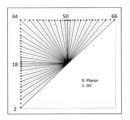
- FIG. 1 is a diagram illustrating an intra prediction mode according to an embodiment.
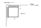
- FIG. 1 is a diagram for explaining a TIMD according to an embodiment.
- FIG. 1 is a diagram illustrating a configuration of an intra prediction unit according to an embodiment.
- FIG. 11 is a diagram for explaining the operation of an intra prediction unit according to the embodiment.
- FIG. 2 is a diagram illustrating a configuration of a decoding device according to an embodiment.
- FIG. 1 is a diagram illustrating a configuration of an intra prediction unit according to an embodiment.
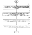
- FIG. 11 is a diagram illustrating an example of the operation of an intra prediction unit according to the embodiment.
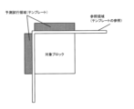
- FIG. 13 is a diagram for explaining a modified example of the TIMD according to the embodiment.
- intra-prediction mode derivation technology using templates, a prediction mode that provides the best results in intra-prediction cost calculations in the trial prediction area on the encoding device side and the decoding device side, or a prediction mode whose cost calculation results exceed a threshold even if the derivation is in progress, is selected.
- a prediction mode that provides the best results in intra-prediction cost calculations in the trial prediction area on the encoding device side and the decoding device side, or a prediction mode whose cost calculation results exceed a threshold even if the derivation is in progress is selected.
- such technology has room for improvement in terms of improving prediction accuracy in intra-prediction.
- the present disclosure provides an intra prediction device, an encoding device, a decoding device, and a program that can improve the prediction accuracy in intra prediction.
- the following describes an encoding device and a decoding device equipped with an intra prediction device according to an embodiment, with reference to the drawings.
- the encoding device and the decoding device respectively encode and decode video (i.e., moving images) as represented by MPEG.
- decode video i.e., moving images
- Fig. 1 is a diagram showing the configuration of the encoding device 1 according to this embodiment.
- the encoding device 1 is a device that encodes an input image to generate a bit stream and outputs the bit stream.
- the encoding device 1 has a block division unit 100, a subtraction unit 110, a transformation and quantization unit 120, an entropy coding unit 130, an inverse quantization and inverse transform unit 140, a synthesis unit 150, a memory 160, and a prediction unit 170.
- the block division unit 100 divides an original image, which is an input image in units of frames (or pictures) that make up a moving image, into a plurality of image blocks, and outputs the image blocks obtained by division to the subtraction unit 110.
- the size of the image block is, for example, 32 x 32 pixels, 16 x 16 pixels, 8 x 8 pixels, or 4 x 4 pixels.
- the shape of the image block is not limited to a square, but may be a rectangle (non-square).
- An image block is the unit by which the encoding device 1 performs encoding, and is the unit by which the decoding device performs decoding. Such an image block is also called a coding block (CU).
- the input image is composed of a luminance signal (Y) and a color difference signal (Cb, Cr), and each pixel in the input image is composed of a luminance component (Y) and a color difference component (Cb, Cr).
- the encoding device 1 supports three color difference formats, for example, 4:4:4, 4:2:2, and 4:2:0.
- the block division unit 100 outputs a luminance block by performing block division on the luminance signal, and outputs a color difference block by performing block division on the color difference signal.
- the shape of the block division may be the same for the luminance signal and the color difference signal, or the division shape may be independently controllable for the luminance signal and the color difference signal.
- the subtraction unit 110 calculates a prediction residual that represents the difference (error) between the coded block output by the block division unit 100 and a predicted block obtained by predicting the coded block by the prediction unit 170. Specifically, the subtraction unit 110 calculates the prediction residual by subtracting each pixel value of the predicted block from each pixel value of the block, and outputs the calculated prediction residual to the transformation and quantization unit 120.
- the transform/quantization unit 120 performs transform processing and quantization processing on a block-by-block basis.
- the transform/quantization unit 120 has a transform unit 121 and a quantization unit 122.
- the transform unit 121 performs a transform process on the prediction residual output by the subtraction unit 110 to calculate transform coefficients, and outputs the calculated transform coefficients to the quantization unit 122.
- the transform refers to, for example, a discrete cosine transform (DCT), a discrete sine transform (DST), a Karhunen Loeve transform (KLT), etc.
- the transform process includes a transform skip in which no transform process is performed.
- the transform skip also includes a transform that applies a transform process only horizontally, or a transform that applies a transform process only vertically.
- the transform unit 121 may also perform a secondary transform process in which a further transform process is applied to the transform coefficients obtained by the transform process.
- the secondary transform process may be applied only to a partial area of the transform coefficients.
- the quantization unit 122 quantizes the transform coefficients output by the transform unit 121 using a quantization parameter and a quantization matrix, and outputs the quantized transform coefficients to the entropy coding unit 130 and the inverse quantization and inverse transform unit 140.
- the quantization parameter is a parameter that is commonly applied to each transform coefficient in a block and determines the coarseness of quantization.
- the quantization matrix is a matrix whose elements are the quantization values used when quantizing each transform coefficient.
- the entropy coding unit 130 performs entropy coding on the quantized transform coefficients output by the quantization unit 122, compresses the data, generates a bitstream, and outputs the bitstream to the outside of the coding device 1.
- Huffman codes For entropy coding, Huffman codes, CABAC (Context-based Adaptive Binary Arithmetic Coding), etc. can be used.
- CABAC Context-based Adaptive Binary Arithmetic Coding
- the entropy coding unit 130 receives input of prediction-related information (flags and indexes) from the prediction unit 170, and also codes the input information and outputs the bitstream.
- the inverse quantization and inverse transform unit 140 performs inverse quantization and inverse transform processing on a block-by-block basis.
- the inverse quantization and inverse transform unit 140 includes an inverse quantization unit 141 and an inverse transform unit 142.
- the inverse quantization unit 141 performs an inverse quantization process corresponding to the quantization process performed by the quantization unit 122. Specifically, the inverse quantization unit 141 reconstructs the transform coefficients by inverse quantizing the quantized transform coefficients output by the quantization unit 122 using a quantization parameter and a quantization matrix, and outputs the reconstructed transform coefficients to the inverse transform unit 142.
- the inverse transform unit 142 performs an inverse transform process corresponding to the transform process performed by the transform unit 121. For example, if the transform unit 121 performs a discrete cosine transform, the inverse transform unit 142 performs an inverse discrete cosine transform. The inverse transform unit 142 performs an inverse transform process on the transform coefficients output by the inverse quantization unit 141 to reconstruct the prediction residual, and outputs the reconstructed prediction residual, which is the reconstructed prediction residual, to the synthesis unit 150.
- the synthesis unit 150 synthesizes the reconstructed prediction residual output by the inverse transform unit 142 by adding it to the predicted block output by the prediction unit 170 on a pixel-by-pixel basis.
- the synthesis unit 150 adds each pixel value of the reconstructed prediction residual to each pixel value of the predicted block to decode (reconstruct) the block, and outputs the reconstructed block to the memory 160.
- the reconstructed block is also referred to as a decoded block.
- the memory 160 stores the reconstructed blocks output by the synthesis unit 150, and accumulates the reconstructed blocks as decoded images on a frame-by-frame basis.
- the memory 160 outputs the stored reconstructed blocks or decoded images to the prediction unit 170. Note that a loop filter may be provided between the synthesis unit 150 and the memory 160.
- the prediction unit 170 performs prediction on a block-by-block basis.
- the prediction unit 170 has an inter prediction unit 171, an intra prediction unit 172, and a switching unit 173.
- the inter prediction unit 171 uses the decoded image stored in the memory 160 as a reference image to calculate a motion vector by a technique such as block matching, predicts the coding block to generate an inter prediction block, and outputs the generated inter prediction block to the switching unit 173.
- the inter prediction unit 171 selects an optimal inter prediction method from inter prediction using multiple reference images (typically bi-prediction) and inter prediction using one reference image (unidirectional prediction), and performs inter prediction using the selected inter prediction method.
- the inter prediction unit 171 outputs information related to the inter prediction (motion vectors, etc.) to the entropy coding unit 130.
- the intra prediction unit 172 generates an intra prediction block by referring to decoded pixels surrounding a block from among the decoded images stored in the memory 160, and outputs the generated intra prediction block to the switching unit 173.
- the intra prediction unit 172 selects an intra prediction mode to be applied to a predictive coding block of intra prediction from among multiple intra prediction modes, and predicts the coding block of intra prediction using the selected intra prediction mode.
- the intra prediction unit 172 outputs information related to the selected intra prediction mode to the entropy coding unit 130.
- the switching unit 173 switches between the inter prediction block output by the inter prediction unit 171 and the intra prediction block output by the intra prediction unit 172, and outputs one of the prediction blocks to the subtraction unit 110 and the synthesis unit 150.
- FIG. 2 is a diagram for explaining intra prediction modes according to this embodiment.
- the intra prediction unit 172 performs intra prediction for the coding block.
- the candidates for the intra prediction mode of the luminance block are planar prediction, DC prediction, and 65 types of directional prediction, for a total of 67 types of intra prediction modes.
- Prediction mode mode "0" is planar prediction
- prediction mode mode “1” is DC prediction
- prediction mode modes "2" to “66” are directional prediction.
- the direction of the arrow indicates the prediction direction (reference direction)
- the starting point of the arrow indicates the position of the pixel to be predicted
- the end point of the arrow indicates the position of the reference pixel used to predict this pixel to be predicted (also called the "reference pixel position”).
- a total of 65 modes of directional prediction are prepared, and the selectable prediction direction is determined by the shape (aspect ratio) of the block. Note that in this embodiment, it is assumed that there are 65 directional prediction directions, but there may be more than 65 directional prediction directions.
- Mode "2" which is a prediction mode that references the bottom-left direction
- mode "66” which is a prediction mode that references the top-right direction
- Mode numbers are assigned at predetermined angles in a clockwise direction from mode “2" to mode "66”.
- Mode "34” is a prediction mode that references the top-left direction. Specifically, if the horizontal direction is 0°, the prediction direction of mode “2” is -45°, the prediction direction of mode “18” is 0°, the prediction direction of mode “34” is 45°, the prediction direction of mode “50” is 90°, and the prediction direction of mode “66” is 135°.
- Mode “18” is also referred to as the horizontal direction
- mode "50” is also referred to as vertical prediction.
- directional predictions below mode “34”, i.e., modes “2” to “33”, are directional predictions that refer to the left side of the coding block, and the prediction direction is toward the left side of the coding block.
- directional predictions above mode “34”, i.e., modes “35” to “66” are directional predictions that refer to the top side of the coding block, and the prediction direction is toward the top of the coding block.
- Template-based intra mode derivation is also called TIMD (Templated-based Intra Mode Derivation).
- Fig. 3 is a diagram for explaining TIMD according to this embodiment.
- the intra prediction unit 172 according to this embodiment performs intra prediction corresponding to TIMD.
- the surrounding area of the target block for intra prediction is used as a prediction trial area (template), and the encoding side and decoding side perform prediction trials on the prediction trial area using a common algorithm, thereby deriving an intra prediction mode common to the encoding side and decoding side.
- This makes it possible to reduce the overhead of signaling the intra prediction mode, and to derive additional directional prediction that subdivides between conventional prediction directions to create new prediction directions.
- the entropy encoding unit 130 may signal a flag indicating that TIMD is to be applied to the decoding side.
- TIMD may be applied only to luminance signal blocks, and may not be applied to chrominance signal blocks.
- the intra prediction unit 172 identifies an adjacent decoded area adjacent to the target block as a prediction trial area (template), and identifies a decoded area outside the prediction trial area as a reference area.
- the reference area is a set of adjacent reference pixels (reference pixel line) to the left and above the prediction trial area.
- the width L of the prediction trial area may be variably set according to the size of the target block (i.e., the width M x height N of the target block). For example, if the size of the target block is 8 or less, the width L of the prediction trial area may be set to 2, and if not, the width L of the prediction trial area may be set to 4.
- the intra prediction unit 172 calculates the cost using a cost function by performing a prediction trial to predict the prediction trial area from the reference area for each intra prediction mode.
- the cost function may be, for example, SAD (Sum of Absolute Differences) or SATD (Sum of Absolute Transformed Differences).
- the intra prediction unit 172 predicts the prediction trial area from the reference area using a candidate intra prediction mode, and calculates the SAD or SATD between the prediction result (each predicted pixel) and the prediction trial area (each decoded pixel) as the cost.
- the number of conventional directional predictions is 65 (65 directions), but the number of directional predictions in which prediction trials are performed may be 129 (129 directions). In other words, it is possible to apply additional directional predictions in which the conventional prediction directions are subdivided to create new prediction directions.
- the intra prediction unit 172 determines at least one intra prediction mode to be used for intra prediction according to the cost calculated for each intra prediction mode. For example, the intra prediction unit 172 performs cost calculations for all candidate intra prediction modes and determines the intra prediction mode with the smallest cost as the final intra prediction mode for the target block. However, the intra prediction unit 172 does not necessarily have to perform cost calculations for all candidate intra prediction modes. The intra prediction unit 172 may perform cost calculations for each candidate intra prediction mode, and if the calculated cost satisfies a predetermined threshold condition, determine the intra prediction mode that satisfies the threshold condition as the final intra prediction mode for the target block.
- the intra prediction unit 172 uses adjacent decoded regions adjacent to the target block as reference regions (reference pixels) to predict each pixel of the target block using the final intra prediction mode determined based on the cost, and generates a predicted block (intra prediction block).
- the number of final intra prediction modes determined based on the calculated costs is not limited to one, and two or more intra prediction modes selected in ascending order of cost may be determined.
- the intra prediction unit 172 may determine two final intra prediction modes based on the calculated costs, generate two prediction blocks by intra prediction using each of these two intra prediction modes, and output the final prediction block by taking a weighted average (weighted synthesis) of the two prediction blocks according to the cost of each intra prediction mode.
- FIG. 4 is a diagram showing the configuration of the intra prediction unit 172 according to this embodiment.
- Fig. 5 is a diagram for explaining the operation of the intra prediction unit 172 according to this embodiment.
- the intra prediction unit 172 has a region identification unit 1721, a cost calculation unit 1722, a prediction mode determination unit 1723, and a prediction block generation unit 1724.
- the region identification unit 1721 identifies an adjacent decoded region adjacent to the target block for intra prediction as a prediction trial region, and identifies a decoded region outside the prediction trial region as a reference region.
- the prediction trial region includes multiple sub-regions classified according to their relative positional relationship with the target block.
- the multiple sub-regions include a left sub-region A, which is an adjacent decoded region on the left side of the target block, and an upper sub-region B, which is an adjacent decoded region above the target block, as shown in FIG. 5.
- the cost calculation unit 1722 calculates the cost (SAD or SATD) using a cost function by performing a prediction trial for each intra prediction mode, predicting the prediction trial region from the reference region.
- the cost calculation unit 1722 weights each sub-region when calculating the cost of each intra prediction mode. That is, the cost calculation unit 1722 takes into account the importance of each sub-region determined according to the intra prediction mode being tried, and performs weighting to emphasize the cost of sub-regions with high importance. This makes it possible to improve the prediction accuracy of intra prediction.
- the cost calculation unit 1722 sets a weight for each of the multiple sub-regions according to the reference region position, which is the position of the reference region referenced in the intra prediction mode used in the prediction trial, and the position of each of the multiple sub-regions. Specifically, the cost calculation unit 1722 sets a larger weight for a second sub-region, whose distance from the reference region position is a second distance longer than the first distance, compared to the weight for a first sub-region, whose distance from the reference region position is a first distance.
- FIG. 5(a) is a diagram for explaining cost calculation when the intra prediction mode to be tried is mode 2.
- the prediction direction is -45° when the horizontal direction is 0°.
- Mode 2 is a directional prediction that references the left reference region out of the left and upper reference regions.
- the reference region position which is the position of the reference region to be referenced, is on the left side, and this left reference region and left sub-region A are adjacent to each other, but the upper sub-region B is separated from the left reference region.
- the cost calculation unit 1722 sets a weight that places more importance on the upper subregion B relative to the left subregion A.
- the cost calculation unit 1722 calculates the SAD (or SATD) between the prediction result of the left sub-region A and the left sub-region A as cost A, and calculates the SAD (or SATD) between the prediction result of the upper sub-region B and the upper sub-region B as cost B.
- the cost calculation unit 1722 weights the cost A with a first weight, and weights the cost B with a second weight that is greater than the first weight.
- the cost calculation unit 1722 calculates the sum (or average) of the weighted costs A and B as the cost of mode 2.
- the cost calculation unit 1722 can calculate a weighted cost that prioritizes the upper sub-region B, which has low prediction accuracy, by regarding it as a sub-region of high importance, and can calculate a more appropriate cost for mode 2.
- mode 2 has been described as an example in FIG. 5(a)
- a similar weighted cost calculation can be applied to all directional predictions that refer to the left side (for example, modes 2 to 33, and prediction modes intermediate between these).
- FIG. 5(b) is a diagram for explaining cost calculation when the intra prediction mode to be tried is mode 66.
- Mode 66 has a prediction direction of 135° when the horizontal direction is 0°.
- Mode 66 is a directional prediction that references the upper reference region of the left and upper reference regions.
- the reference region position which is the position of the reference region to be referenced, is on the upper side, and this upper reference region and upper sub-region B are adjacent to each other, but the left sub-region A is separated from the upper reference region.
- the cost calculation unit 1722 sets a weight that places more importance on the left sub-region A than on the upper sub-region B.
- the cost calculation unit 1722 calculates the SAD (or SATD) between the prediction result of the left sub-region A and the left sub-region A as cost A, and calculates the SAD (or SATD) between the prediction result of the upper sub-region B and the upper sub-region B as cost B.
- the cost calculation unit 1722 weights the cost B with a first weight, and weights the cost A with a second weight that is greater than the first weight. Then, the cost calculation unit 1722 calculates the sum (or average) of the weighted costs A and B as the cost of mode 66.
- the cost calculation unit 1722 can calculate a weighted cost that prioritizes the left subregion A, which has low prediction accuracy, by regarding it as a subregion of high importance, and can calculate a more appropriate cost for mode 66.
- mode 66 has been described as an example in FIG. 5(b)
- a similar weighted cost calculation can be applied to all directional predictions that refer to the upper side (for example, modes 35 to 66, and prediction modes intermediate between these).
- the cost calculation unit 1722 has a weight setting unit 1722a, a prediction trial unit 1722b, and a weight calculation unit 1722c.
- the weight setting unit 1722a sets a weight for each sub-region according to the intra prediction mode.
- the prediction trial unit 1722b performs a prediction trial for each sub-region using the intra prediction mode.
- the weight calculation unit 1722c calculates a cost for each sub-region and applies a weight according to the result of the prediction trial, to derive a weighted cost for the intra prediction mode.
- weight setting unit 1722a may set 0.5 as the variable ⁇ for all directional predictions that refer to both the left and upper reference regions, as well as for planar predictions and DC predictions.
- weighted cost cost A x 0.5 + cost B x 0.5.
- the prediction mode determination unit 1723 determines at least one intra prediction mode to be used for intra prediction according to the weighted cost calculated by the cost calculation unit 1722 for each intra prediction mode. For example, the prediction mode determination unit 1723 performs cost calculation for all candidate intra prediction modes and determines the intra prediction mode with the smallest cost as the final intra prediction mode of the target block. However, the cost calculation unit 1722 does not necessarily need to perform cost calculation for all candidate intra prediction modes. While the cost calculation unit 1722 performs cost calculation for each candidate intra prediction mode, if the calculated cost satisfies a predetermined threshold condition, the prediction mode determination unit 1723 may determine the intra prediction mode that satisfies the threshold condition as the final intra prediction mode of the target block. The prediction mode determination unit 1723 may determine two or more intra prediction modes selected in ascending order of cost as the final intra prediction mode of the target block.
- the prediction block generation unit 1724 predicts the target block by intra prediction using at least one intra prediction mode determined by the prediction mode determination unit 1723, and generates a prediction block.
- the prediction mode determination unit 1723 determines one intra prediction mode
- the prediction block generation unit 1724 uses decoded pixels surrounding the target block as reference pixels to generate an intra prediction block by the one intra prediction mode, and outputs the generated intra prediction block.
- the prediction block generation unit 1724 may generate multiple prediction blocks by intra prediction using each of the multiple intra prediction modes, and output a prediction block obtained by weighting the average (weighted synthesis) of the multiple prediction blocks according to the cost of each intra prediction mode.
- FIG. 6 is a diagram showing the configuration of a decoding device 2 according to this embodiment.
- the decoding device 2 is a device that derives and outputs a decoded image from an input bit stream.
- the decoding device 2 has an entropy decoding unit 200, an inverse quantization and inverse transform unit 210, a synthesis unit 220, a memory 230, and a prediction unit 240.
- the entropy decoding unit 200 decodes the bitstream generated by the encoding device 1, and outputs the quantized transform coefficients to the inverse quantization and inverse transform unit 210.
- the entropy decoding unit 200 also obtains information related to prediction (intra prediction and inter prediction), and outputs the obtained information to the prediction unit 240.
- the entropy decoding unit 200 may obtain a flag indicating that TIMD is applied, and output the flag to the prediction unit 240.
- the inverse quantization and inverse transform unit 210 performs inverse quantization and inverse transform processing on a block-by-block basis.
- the inverse quantization and inverse transform unit 210 includes an inverse quantization unit 211 and an inverse transform unit 212.
- the inverse quantization unit 211 performs an inverse quantization process corresponding to the quantization process performed by the quantization unit 122 of the encoding device 1.
- the inverse quantization unit 211 reconstructs the transform coefficients of the encoding block by inverse quantizing the quantized transform coefficients output by the entropy decoding unit 200 using a quantization parameter and a quantization matrix, and outputs the reconstructed transform coefficients to the inverse transform unit 212.
- the inverse transform unit 212 performs inverse transform processing corresponding to the transform processing performed by the transform unit 121 of the encoding device 1.
- the inverse transform unit 212 performs inverse transform processing on the transform coefficients output by the inverse quantization unit 211 to reconstruct the prediction residual, and outputs the reconstructed prediction residual, which is the reconstructed prediction residual, to the synthesis unit 220.
- the inverse transform processing includes transform skip, in which the inverse transform processing is not performed.
- the inverse transform unit 212 may perform inverse secondary transform processing in which further inverse transform processing is applied to the signal obtained by the inverse transform processing.
- the synthesis unit 220 synthesizes the prediction residual output by the inverse transform unit 212 and the prediction block output by the prediction unit 240 by adding them together on a pixel-by-pixel basis, decodes (reconstructs) the original block, and outputs the reconstructed block to the memory 230.
- the memory 230 stores the reconstructed blocks output by the synthesis unit 220, and accumulates the reconstructed blocks as decoded images on a frame-by-frame basis.
- the memory 230 outputs the reconstructed blocks or the decoded images to the prediction unit 240.
- the memory 230 also outputs the decoded images on a frame-by-frame basis to the outside of the decoding device 2. Note that a loop filter may be provided between the synthesis unit 220 and the memory 230.
- the prediction unit 240 performs prediction on a block-by-block basis.
- the prediction unit 240 has an inter prediction unit 241, an intra prediction unit 242, and a switching unit 243.
- the inter prediction unit 241 predicts the coding block by inter prediction using the decoded image stored in the memory 230 as a reference image.
- the inter prediction unit 241 generates an inter prediction block by performing inter prediction according to the motion vector information output by the entropy decoding unit 200, and outputs the generated inter prediction block to the switching unit 243.
- the intra prediction unit 242 generates an intra prediction block by referring to decoded pixels surrounding the block to be predicted (encoded block) among the decoded images stored in the memory 230, and outputs the generated intra prediction block to the switching unit 243.
- the intra prediction unit 242 according to this embodiment performs intra prediction corresponding to the above-mentioned TIMD.
- the switching unit 243 switches between the inter prediction block output by the inter prediction unit 241 and the intra prediction block output by the intra prediction unit 242, and outputs one of the prediction blocks to the synthesis unit 220.
- FIG. 7 is a diagram showing the configuration of the intra prediction unit 242 according to this embodiment.
- the intra prediction unit 242 has an area identification unit 2421, a cost calculation unit 2422, a prediction mode determination unit 2423, and a prediction block generation unit 2424.
- the area identification unit 2421, the cost calculation unit 2422, the prediction mode determination unit 2423, and the prediction block generation unit 2424 perform the same processing as the area identification unit 1721, the cost calculation unit 1722, the prediction mode determination unit 1723, and the prediction block generation unit 1724 on the encoding side, respectively.
- FIG. 8 is a diagram showing an operation example of the intra prediction unit 242 on the decoding side according to this embodiment.
- the operation of the intra prediction unit 242 on the decoding side will be described as an example, but the intra prediction unit 172 on the encoding side also performs the same operation as the intra prediction unit 242 on the decoding side.
- the region identification unit 2421 identifies an adjacent decoded region adjacent to the target block for intra prediction as a prediction trial region, and identifies a decoded region outside the prediction trial region as a reference region.
- the prediction trial region includes a left sub-region A, which is an adjacent decoded region on the left side of the target block, and an upper sub-region B, which is an adjacent decoded region above the target block.
- the cost calculation unit 2422 calculates the cost (SAD or SATD) using a cost function by performing a prediction trial for each intra prediction mode, predicting the prediction trial region from the reference region.
- the cost calculation unit 2422 weights each subregion when calculating the cost of each intra prediction mode. That is, the cost calculation unit 2422 considers the importance of each subregion determined according to the intra prediction mode to be tried, and performs weighting to emphasize the cost of the subregion with high importance.
- cost A is the cost calculated for the left subregion A
- cost B is the cost calculated for the upper subregion B
- ⁇ is a variable (weight) that takes a value from 0 to 1.
- the cost calculation unit 2422 performs the following weighted cost calculation for each directional prediction:
- the cost calculation unit 2422 sets a value greater than 0.5 as the variable ⁇ .
- the variable ⁇ is set to 0.8.
- the "weighted cost cost A x 0.2 + cost B x 0.8" is obtained, and the cost calculation unit 2422 performs cost calculation with a larger weight for the upper sub-region B.
- the cost calculation unit 2422 sets a value smaller than 0.5 as the variable ⁇ .
- the variable ⁇ is set to 0.2.
- the "weighted cost cost A x 0.8 + cost B x 0.2" is obtained, and the cost calculation unit 2422 performs cost calculation with a larger weight for the left sub-region A.
- the prediction mode determination unit 2423 determines at least one intra prediction mode to be used for intra prediction, depending on the weighted cost calculated for each intra prediction mode by the cost calculation unit 2422. For example, the prediction mode determination unit 2423 determines the intra prediction mode with the smallest cost (weighted cost) as the final intra prediction mode for the target block.
- step S4 the prediction block generation unit 2424 predicts the target block by intra prediction using at least one intra prediction mode determined by the prediction mode determination unit 2423, and generates a prediction block.
- Each intra prediction unit 172, 242 constitutes an intra prediction device that performs intra prediction in units of blocks obtained by dividing an image.
- Each intra prediction device includes a region specification unit 1721, 2421 that specifies an adjacent decoded region adjacent to a target block of intra prediction as a prediction trial region and specifies a decoded region outside the prediction trial region as a reference region, a cost calculation unit 1722, 2422 that calculates a cost using a cost function by performing a prediction trial of predicting the prediction trial region from the reference region for each intra prediction mode, and a prediction mode determination unit 1723, 2423 that determines at least one intra prediction mode to be used for intra prediction according to the cost.
- the prediction trial region includes a plurality of sub-regions classified according to a relative positional relationship with the target block.
- the cost calculation unit 1722, 2422 performs weighting for each sub-region when calculating the cost of each intra prediction mode. This makes it possible to improve the prediction accuracy in intra prediction when performing template-based intra mode derivation.
- FIG. 9 is a diagram for explaining a modified example of TIMD according to the embodiment.
- the region identification unit 1721 (2421) identifies an adjacent decoded region adjacent to the target block of intra prediction as a reference region and identifies a decoded region outside the prediction trial region as a reference region, but is not limited thereto.
- FIG. 9 is a diagram for explaining a modified example of TIMD according to the embodiment.
- the region identification unit 1721 (2421) identifies an adjacent decoded region adjacent to the target block of intra prediction as a reference region and identifies a decoded region of the reference region as a prediction trial region.
- the region identification unit 1721 may identify a decoded region around the target block of intra prediction as a prediction trial region and identify a decoded region adjacent to the prediction trial region as a reference region.
- the prediction mode determination unit 1723 may determine, as the final intra prediction mode, the intra prediction mode (directional prediction) selected based on the cost, rotated by 180 degrees.
- the prediction trial area includes a left sub-area A, which is an adjacent decoded area to the left of the target block, and an upper sub-area B, which is an adjacent decoded area to the upper side of the target block, as multiple sub-areas classified according to their relative positional relationship with the target block.
- the prediction trial area has two sub-areas.
- the prediction trial region is not limited to having two sub-regions, and may have three or more sub-regions.
- the left sub-region A may be divided vertically into two, and an upper left sub-region A1 and a lower left sub-region A2 may be defined.
- the upper sub-region B may be divided horizontally into two, and an upper left sub-region B1 and an upper right sub-region B2 may be defined.
- the prediction trial region has four sub-regions (A1, A2, B1, B2).
- the encoding-side cost calculation unit 1722 and the decoding-side cost calculation unit 2422 each calculate the cost of each of these four sub-regions, and may calculate the weighted cost of each intra prediction mode by weighting the cost of each of the four sub-regions according to the intra prediction mode for each intra prediction mode to be tried.
- the cost calculation unit may set zero as the weight for some of the multiple sub-regions, thereby calculating the cost only for sub-regions that are different from the some sub-regions.
- a program may be provided that causes a computer to execute each process performed by the image processing device (encoding device 1, decoding device 2).
- the program may be recorded on a computer-readable medium.
- the computer-readable medium on which the program is recorded may be a non-transient recording medium.
- the non-transient recording medium is not particularly limited, and may be, for example, a recording medium such as a CD-ROM or DVD-ROM.
- Circuits that execute each process performed by the image processing device (encoding device 1, decoding device 2) may be integrated, and the image processing device may be configured as a semiconductor integrated circuit (chip set, SoC).
- the functions realized by the image processing device may be implemented in circuitry or processing circuitry, including general-purpose processors, application-specific processors, integrated circuits, ASICs (Application Specific Integrated Circuits), CPUs (Central Processing Units), conventional circuits, and/or combinations thereof, programmed to realize the described functions.
- Processors include transistors and other circuits and are considered to be circuitry or processing circuitry.
- Processors may be programmed processors that execute programs stored in memory.
- circuitry, units, and means are hardware that is programmed to realize the described functions or hardware that executes them.
- the hardware may be any hardware disclosed herein or any hardware known to be programmed or capable of performing the described functions. If the hardware is a processor considered to be a type of circuitry, the circuitry, means, or unit is a combination of hardware and software used to configure the hardware and/or processor.
- the terms “based on” and “depending on/in response to” do not mean “based only on” or “only in response to,” unless otherwise specified.
- the term “based on” means both “based only on” and “based at least in part on.”
- the term “in response to” means both “only in response to” and “at least in part on.”
- the terms “include,” “comprise,” and variations thereof do not mean including only the items listed, but may include only the items listed, or may include additional items in addition to the items listed.
- the term “or” as used in this disclosure is not intended to mean an exclusive or.
- any reference to elements using designations such as “first,” “second,” etc., as used in this disclosure is not intended to generally limit the quantity or order of those elements. These designations may be used herein as a convenient way to distinguish between two or more elements. Thus, a reference to a first and second element does not imply that only two elements may be employed therein, or that the first element must precede the second element in some manner.
- articles are added by translation such as, for example, a, an, and the in English, these articles are intended to include the plural unless the context clearly indicates otherwise.
- An intra prediction device (172, 242) that performs intra prediction on a block basis obtained by dividing an image, A region specifying means (1721, 2421) for specifying a decoded region around the target block of the intra prediction as a prediction trial region and for specifying a decoded region adjacent to the prediction trial region as a reference region; a cost calculation means (1722, 2422) for calculating a cost using a cost function by performing a prediction trial for predicting the prediction trial area from the reference area for each intra prediction mode; A prediction mode determination means (1723, 2423) for determining at least one intra prediction mode to be used for the intra prediction in accordance with the cost, the prediction trial region includes a plurality of sub-regions classified according to a relative positional relationship with the target block, The intra prediction device, wherein the cost calculation means performs weighting for each of the sub-regions when calculating the cost for each intra prediction mode.
- the cost calculation means sets a weight for each of the plurality of sub-regions depending on a reference region position, which is a position of the reference region referenced in the intra prediction mode used for the prediction trial, and a position of each of the plurality of sub-regions.
- the cost calculation means sets a weight for a second sub-region whose distance from the reference region position is a second distance longer than the first distance to be larger than a weight for a first sub-region whose distance from the reference region position is a first distance.
- the cost calculation means calculates, for each intra prediction mode used in the trial prediction, a weight setting means (1722a, 2422a) for setting a weight for each of the sub-regions according to the intra prediction mode; A prediction trial means (1722b, 2422b) for performing a prediction trial for each of the sub-regions using the intra prediction mode; and weighting calculation means (1722c, 2422c) for calculating the cost and applying the weights for each of the sub-regions depending on the results of the prediction trials to derive a weighted cost for the intra prediction mode,
- the intra prediction device according to any one of claims 1 to 3, wherein the prediction mode determination means determines at least one intra prediction mode to be used for the intra prediction in accordance with the weighted cost of each intra prediction mode.
- the plurality of sub-regions include: A left sub-region (A) which is a decoded region on the left side of the current block; and an upper sub-region (B) that is a decoded region above the current block.
- a decoding device (2) comprising an intra prediction device according to any one of Supplementary Notes 1 to 5.
- Encoding device 2 Decoding device 100: Block division unit 110: Subtraction unit 120: Transformation and quantization unit 121: Transformation unit 122: Quantization unit 130: Entropy encoding unit 140: Inverse quantization and inverse transform unit 141: Inverse quantization unit 142: Inverse transform unit 150: Synthesis unit 160: Memory 170: Prediction unit 171: Inter prediction unit 172: Intra prediction unit 173: Switching unit 200: Entropy decoding unit 210: Inverse quantization and inverse transform unit 211: Inverse quantization unit 212: Inverse transform unit 220: Synthesis unit 230: Memory 240: Prediction unit 241: Inter prediction unit 242: Intra prediction unit 243: Switching unit 1721: Area identification unit 1722: Cost calculation unit 1722a: Weight setting unit 1722b: Trial prediction unit 1722c: Weight calculation unit 1723: Prediction mode determination unit 1724: Prediction block generation unit 2421: Area identification unit 2422: Cost calculation unit 2422a: Weight setting unit 2422b: Trial prediction unit 2422c: Prediction
Landscapes
- Engineering & Computer Science (AREA)
- Multimedia (AREA)
- Signal Processing (AREA)
- Compression Or Coding Systems Of Tv Signals (AREA)
Priority Applications (3)
| Application Number | Priority Date | Filing Date | Title |
|---|---|---|---|
| EP24832127.5A EP4738817A1 (en) | 2023-06-29 | 2024-06-28 | Intra prediction device, encoding device, decoding device, and program |
| CN202480043402.1A CN121444434A (zh) | 2023-06-29 | 2024-06-28 | 帧内预测装置、编码装置、解码装置及程序 |
| JP2025530246A JPWO2025005270A1 (https=) | 2023-06-29 | 2024-06-28 |
Applications Claiming Priority (2)
| Application Number | Priority Date | Filing Date | Title |
|---|---|---|---|
| JP2023107062 | 2023-06-29 | ||
| JP2023-107062 | 2023-06-29 |
Related Child Applications (1)
| Application Number | Title | Priority Date | Filing Date |
|---|---|---|---|
| US19/435,660 Continuation US20260129190A1 (en) | 2023-06-29 | 2025-12-29 | Intra prediction apparatus, encoding apparatus, decoding apparatus, and program |
Publications (1)
| Publication Number | Publication Date |
|---|---|
| WO2025005270A1 true WO2025005270A1 (ja) | 2025-01-02 |
Family
ID=93938496
Family Applications (1)
| Application Number | Title | Priority Date | Filing Date |
|---|---|---|---|
| PCT/JP2024/023601 Ceased WO2025005270A1 (ja) | 2023-06-29 | 2024-06-28 | イントラ予測装置、符号化装置、復号装置、及びプログラム |
Country Status (4)
| Country | Link |
|---|---|
| EP (1) | EP4738817A1 (https=) |
| JP (1) | JPWO2025005270A1 (https=) |
| CN (1) | CN121444434A (https=) |
| WO (1) | WO2025005270A1 (https=) |
Citations (2)
| Publication number | Priority date | Publication date | Assignee | Title |
|---|---|---|---|---|
| JP2019535211A (ja) * | 2016-10-14 | 2019-12-05 | インダストリー アカデミー コーオペレイション ファウンデーション オブ セジョン ユニバーシティ | 画像の符号化/復号化方法及び装置 |
| JP2023107062A (ja) | 2022-01-21 | 2023-08-02 | 技研株式会社 | ワークの搬送装置 |
-
2024
- 2024-06-28 WO PCT/JP2024/023601 patent/WO2025005270A1/ja not_active Ceased
- 2024-06-28 EP EP24832127.5A patent/EP4738817A1/en active Pending
- 2024-06-28 CN CN202480043402.1A patent/CN121444434A/zh active Pending
- 2024-06-28 JP JP2025530246A patent/JPWO2025005270A1/ja active Pending
Patent Citations (2)
| Publication number | Priority date | Publication date | Assignee | Title |
|---|---|---|---|---|
| JP2019535211A (ja) * | 2016-10-14 | 2019-12-05 | インダストリー アカデミー コーオペレイション ファウンデーション オブ セジョン ユニバーシティ | 画像の符号化/復号化方法及び装置 |
| JP2023107062A (ja) | 2022-01-21 | 2023-08-02 | 技研株式会社 | ワークの搬送装置 |
Non-Patent Citations (2)
| Title |
|---|
| J. R. ARUMUGAM (ITTIAM), A. NATESAN, V. VALVAIKER, J. N. SHINGALA (ITTIAM), T. LU (DOLBY), P. YIN (DOLBY), F. PU (DOLBY), T. SHAO,: "AHG12: Fusion of Intra Template Matching", 29. JVET MEETING; 20230111 - 20230120; TELECONFERENCE; (THE JOINT VIDEO EXPLORATION TEAM OF ISO/IEC JTC1/SC29/WG11 AND ITU-T SG.16 ), 13 January 2023 (2023-01-13), XP030306637 * |
| M. COBAN, R.-L. LIAO, K. NASER, J. STRÖM, L. ZHANG: "Algorithm description of Enhanced Compression Model 9 (ECM 9)", 142. MPEG MEETING; 20230424 - 20230428; ANTALYA; (MOTION PICTURE EXPERT GROUP OR ISO/IEC JTC1/SC29/WG11), 3 July 2023 (2023-07-03), XP030311068 * |
Also Published As
| Publication number | Publication date |
|---|---|
| JPWO2025005270A1 (https=) | 2025-01-02 |
| CN121444434A (zh) | 2026-01-30 |
| EP4738817A1 (en) | 2026-05-06 |
Similar Documents
| Publication | Publication Date | Title |
|---|---|---|
| JP7361522B2 (ja) | 予測ブロック生成装置、画像符号化装置、画像復号装置、及びプログラム | |
| JP7812892B2 (ja) | 予測装置、画像符号化装置、画像復号装置、及びプログラム | |
| WO2020036132A1 (ja) | 画像符号化装置、画像復号装置、及びプログラム | |
| JP7699266B2 (ja) | イントラ予測装置、画像復号装置、及びプログラム | |
| WO2019189904A1 (ja) | イントラ予測装置、画像符号化装置、画像復号装置、及びプログラム | |
| JP2024069638A (ja) | 予測装置、符号化装置、復号装置、及びプログラム | |
| JP7415067B2 (ja) | イントラ予測装置、画像復号装置、及びプログラム | |
| JP7229413B2 (ja) | 画像符号化装置、画像復号装置、及びプログラム | |
| JP7412343B2 (ja) | 画像符号化装置、画像復号装置、及びプログラム | |
| WO2025005270A1 (ja) | イントラ予測装置、符号化装置、復号装置、及びプログラム | |
| JP2023138826A (ja) | イントラ予測装置、画像符号化装置、画像復号装置、及びプログラム | |
| WO2025005269A1 (ja) | 予測装置、符号化装置、復号装置、及びプログラム | |
| US20260129190A1 (en) | Intra prediction apparatus, encoding apparatus, decoding apparatus, and program | |
| JP7531683B2 (ja) | 符号化装置、復号装置、及びプログラム | |
| WO2025070632A1 (ja) | イントラ予測装置及びプログラム | |
| JP7361498B2 (ja) | イントラ予測装置、画像符号化装置、画像復号装置、及びプログラム | |
| JP7444599B2 (ja) | イントラ予測装置、画像符号化装置、画像復号装置、及びプログラム | |
| JP7659103B2 (ja) | インター予測装置、画像符号化装置、画像復号装置、及びプログラム | |
| JP2020053725A (ja) | 予測画像補正装置、画像符号化装置、画像復号装置、及びプログラム | |
| JP2025175152A (ja) | イントラ予測装置、符号化装置、復号装置、及びプログラム | |
| JP2025027687A (ja) | イントラ予測装置、符号化装置、復号装置、及びプログラム | |
| WO2025009513A1 (ja) | 予測装置、符号化装置、復号装置、及びプログラム | |
| JP2024167601A (ja) | 画像処理装置及びプログラム |
Legal Events
| Date | Code | Title | Description |
|---|---|---|---|
| 121 | Ep: the epo has been informed by wipo that ep was designated in this application |
Ref document number: 24832127 Country of ref document: EP Kind code of ref document: A1 |
|
| ENP | Entry into the national phase |
Ref document number: 2025530246 Country of ref document: JP Kind code of ref document: A |
|
| WWE | Wipo information: entry into national phase |
Ref document number: 2025530246 Country of ref document: JP |
|
| WWE | Wipo information: entry into national phase |
Ref document number: 202517131744 Country of ref document: IN |
|
| REG | Reference to national code |
Ref country code: BR Ref legal event code: B01A Ref document number: 112025029233 Country of ref document: BR |
|
| WWP | Wipo information: published in national office |
Ref document number: 202517131744 Country of ref document: IN |
|
| WWE | Wipo information: entry into national phase |
Ref document number: 2024832127 Country of ref document: EP |
|
| NENP | Non-entry into the national phase |
Ref country code: DE |
|
| ENP | Entry into the national phase |
Ref document number: 2024832127 Country of ref document: EP Effective date: 20260129 |
|
| ENP | Entry into the national phase |
Ref document number: 2024832127 Country of ref document: EP Effective date: 20260129 |