WO2025005190A1 - 車両用灯具 - Google Patents
車両用灯具 Download PDFInfo
- Publication number
- WO2025005190A1 WO2025005190A1 PCT/JP2024/023368 JP2024023368W WO2025005190A1 WO 2025005190 A1 WO2025005190 A1 WO 2025005190A1 JP 2024023368 W JP2024023368 W JP 2024023368W WO 2025005190 A1 WO2025005190 A1 WO 2025005190A1
- Authority
- WO
- WIPO (PCT)
- Prior art keywords
- light
- surface portion
- outer lens
- vehicle
- disposed
- Prior art date
- Legal status (The legal status is an assumption and is not a legal conclusion. Google has not performed a legal analysis and makes no representation as to the accuracy of the status listed.)
- Ceased
Links
Images




Classifications
-
- F—MECHANICAL ENGINEERING; LIGHTING; HEATING; WEAPONS; BLASTING
- F21—LIGHTING
- F21S—NON-PORTABLE LIGHTING DEVICES; SYSTEMS THEREOF; VEHICLE LIGHTING DEVICES SPECIALLY ADAPTED FOR VEHICLE EXTERIORS
- F21S43/00—Signalling devices specially adapted for vehicle exteriors, e.g. brake lamps, direction indicator lights or reversing lights
- F21S43/10—Signalling devices specially adapted for vehicle exteriors, e.g. brake lamps, direction indicator lights or reversing lights characterised by the light source
- F21S43/13—Signalling devices specially adapted for vehicle exteriors, e.g. brake lamps, direction indicator lights or reversing lights characterised by the light source characterised by the type of light source
- F21S43/14—Light emitting diodes [LED]
-
- F—MECHANICAL ENGINEERING; LIGHTING; HEATING; WEAPONS; BLASTING
- F21—LIGHTING
- F21S—NON-PORTABLE LIGHTING DEVICES; SYSTEMS THEREOF; VEHICLE LIGHTING DEVICES SPECIALLY ADAPTED FOR VEHICLE EXTERIORS
- F21S43/00—Signalling devices specially adapted for vehicle exteriors, e.g. brake lamps, direction indicator lights or reversing lights
- F21S43/20—Signalling devices specially adapted for vehicle exteriors, e.g. brake lamps, direction indicator lights or reversing lights characterised by refractors, transparent cover plates, light guides or filters
-
- F—MECHANICAL ENGINEERING; LIGHTING; HEATING; WEAPONS; BLASTING
- F21—LIGHTING
- F21S—NON-PORTABLE LIGHTING DEVICES; SYSTEMS THEREOF; VEHICLE LIGHTING DEVICES SPECIALLY ADAPTED FOR VEHICLE EXTERIORS
- F21S43/00—Signalling devices specially adapted for vehicle exteriors, e.g. brake lamps, direction indicator lights or reversing lights
- F21S43/20—Signalling devices specially adapted for vehicle exteriors, e.g. brake lamps, direction indicator lights or reversing lights characterised by refractors, transparent cover plates, light guides or filters
- F21S43/235—Light guides
- F21S43/236—Light guides characterised by the shape of the light guide
- F21S43/237—Light guides characterised by the shape of the light guide rod-shaped
-
- F—MECHANICAL ENGINEERING; LIGHTING; HEATING; WEAPONS; BLASTING
- F21—LIGHTING
- F21S—NON-PORTABLE LIGHTING DEVICES; SYSTEMS THEREOF; VEHICLE LIGHTING DEVICES SPECIALLY ADAPTED FOR VEHICLE EXTERIORS
- F21S43/00—Signalling devices specially adapted for vehicle exteriors, e.g. brake lamps, direction indicator lights or reversing lights
- F21S43/20—Signalling devices specially adapted for vehicle exteriors, e.g. brake lamps, direction indicator lights or reversing lights characterised by refractors, transparent cover plates, light guides or filters
- F21S43/235—Light guides
- F21S43/242—Light guides characterised by the emission area
- F21S43/245—Light guides characterised by the emission area emitting light from one or more of its major surfaces
-
- F—MECHANICAL ENGINEERING; LIGHTING; HEATING; WEAPONS; BLASTING
- F21—LIGHTING
- F21V—FUNCTIONAL FEATURES OR DETAILS OF LIGHTING DEVICES OR SYSTEMS THEREOF; STRUCTURAL COMBINATIONS OF LIGHTING DEVICES WITH OTHER ARTICLES, NOT OTHERWISE PROVIDED FOR
- F21V3/00—Globes; Bowls; Cover glasses
-
- F—MECHANICAL ENGINEERING; LIGHTING; HEATING; WEAPONS; BLASTING
- F21—LIGHTING
- F21W—INDEXING SCHEME ASSOCIATED WITH SUBCLASSES F21K, F21L, F21S and F21V, RELATING TO USES OR APPLICATIONS OF LIGHTING DEVICES OR SYSTEMS
- F21W2103/00—Exterior vehicle lighting devices for signalling purposes
-
- F—MECHANICAL ENGINEERING; LIGHTING; HEATING; WEAPONS; BLASTING
- F21—LIGHTING
- F21W—INDEXING SCHEME ASSOCIATED WITH SUBCLASSES F21K, F21L, F21S and F21V, RELATING TO USES OR APPLICATIONS OF LIGHTING DEVICES OR SYSTEMS
- F21W2103/00—Exterior vehicle lighting devices for signalling purposes
- F21W2103/20—Direction indicator lights
-
- F—MECHANICAL ENGINEERING; LIGHTING; HEATING; WEAPONS; BLASTING
- F21—LIGHTING
- F21W—INDEXING SCHEME ASSOCIATED WITH SUBCLASSES F21K, F21L, F21S and F21V, RELATING TO USES OR APPLICATIONS OF LIGHTING DEVICES OR SYSTEMS
- F21W2103/00—Exterior vehicle lighting devices for signalling purposes
- F21W2103/35—Brake lights
-
- F—MECHANICAL ENGINEERING; LIGHTING; HEATING; WEAPONS; BLASTING
- F21—LIGHTING
- F21Y—INDEXING SCHEME ASSOCIATED WITH SUBCLASSES F21K, F21L, F21S and F21V, RELATING TO THE FORM OR THE KIND OF THE LIGHT SOURCES OR OF THE COLOUR OF THE LIGHT EMITTED
- F21Y2115/00—Light-generating elements of semiconductor light sources
- F21Y2115/10—Light-emitting diodes [LED]
-
- F—MECHANICAL ENGINEERING; LIGHTING; HEATING; WEAPONS; BLASTING
- F21—LIGHTING
- F21Y—INDEXING SCHEME ASSOCIATED WITH SUBCLASSES F21K, F21L, F21S and F21V, RELATING TO THE FORM OR THE KIND OF THE LIGHT SOURCES OR OF THE COLOUR OF THE LIGHT EMITTED
- F21Y2115/00—Light-generating elements of semiconductor light sources
- F21Y2115/30—Semiconductor lasers
Definitions
- the present invention relates to a vehicle lamp.
- Vehicle lighting fixtures are known that have an outer lens that protrudes toward the rear of the vehicle (see, for example, Patent Document 1).
- the present invention was made in consideration of the above, and aims to provide a vehicle lamp that can achieve an appearance in which the outer lens itself appears to be emitting light when illuminated.
- the vehicle lamp of the present invention comprises a light source, an outer lens that is disposed on the front side of the light source when the light source is mounted on the vehicle, the outer lens having a front portion disposed on the front side, an upper surface portion disposed above the front portion, and a lower surface portion disposed below the front portion, the upper surface portion and the lower surface portion extending out so that the front portion is disposed in a position protruding toward the front side, and a light diffusing member that is provided on a target portion of the outer lens different from the front portion, is formed with a higher haze than the front portion, and diffuses light.
- the present invention provides a vehicle lamp that, when illuminated, gives the appearance that the outer lens itself is emitting light.
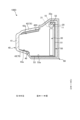
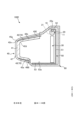
- FIG. 1 is a diagram showing an example of a rear part of a vehicle according to this embodiment.
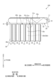
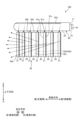
- FIG. 2 is a diagram illustrating an example of a vehicle lamp according to the present embodiment.
- FIG. 3 is a diagram illustrating an example of a vehicle lamp according to the present embodiment.
- FIG. 4 is a diagram illustrating an example of a vehicle lamp according to the present embodiment.
- FIG. 5 is a diagram illustrating an example of a vehicle lamp according to this embodiment.
- FIG. 6 is a diagram showing an example of a lighting state of the vehicle lamp according to this embodiment.
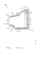
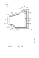
- FIG. 7 is a cross-sectional view showing another example of a vehicle lamp.
- FIG. 8 is a cross-sectional view showing another example of a vehicle lamp.
- FIG. 9 is a cross-sectional view showing another example of a vehicle lamp.
- FIG. 10 is a cross-sectional view showing another example of a vehicle lamp.
- FIG. 11 is a cross-sectional view showing another example of a vehicle lamp
- the front and rear directions are the directions when the device is mounted on a vehicle (mounted on a vehicle).
- the front is the front direction (front side) and the rear is the rear direction (rear side).
- the rear is the front direction (front side) and the front is the rear direction (rear side).
- the outside of the vehicle is the front direction (front side) and the inside of the vehicle is the rear direction (rear side).
- FIG. 1 is a diagram showing an example of the rear of a vehicle 1 according to this embodiment.
- the vehicle 1 includes a vehicle body 2, a running device 3, and a vehicle lamp 100.
- the vehicle body 2 has a driver's cab in which a driver sits.
- the vehicle body 2 is supported by the running device 3.
- the running device 3 has wheels on which tires 4 are mounted, a steering device for changing the traveling direction of the vehicle 1, and a brake device for decelerating or stopping the running device 3.
- the vehicle 1 includes a boarding/alighting door provided on the side of the vehicle body 2, and a back door 7 provided at the rear of the vehicle body 2.
- the boarding/alighting door and the back door 7 are each movably supported by the vehicle body 2 via a hinge mechanism.
- the vehicle lamp 100 is provided on each of the left and right sides of the rear of the vehicle body 2. In this embodiment, the vehicle lamp 100 is provided at the rear of the vehicle body 2. Therefore, the rear side in the fore-and-aft direction will be described as the front side of the vehicle lamp 100, and the front side in the fore-and-aft direction will be described as the back side of the vehicle lamp 100.
- the vehicle lamp 100 includes functional lamps.
- functional lamps include tail lamps that are provided at the rear of the vehicle body 2 and light up in conjunction with the lighting of the head lamps, stop lamps that are provided at the rear of the vehicle body 2 and light up in conjunction with the operation of the brake device, and rear turn signal lamps that are provided at the rear of the vehicle body 2 and light up to indicate to the surroundings the direction in which the vehicle 1 is traveling.
- the vehicle lamps 100 are arranged, for example, on the vehicle body 2 side.
- the vehicle body 2 is a fixed part.
- the back door 7 is a movable part.
- the structure of the vehicle lamp 100 provided on the left rear side of the vehicle body 2 and the structure of the vehicle lamp 100 provided on the right rear side of the vehicle body 2 are symmetrical in the left-right direction and are substantially the same structure.
- the vehicle lamp 100 provided on the right rear side of the vehicle body 2 will be mainly described, and the description of the vehicle lamp 100 provided on the left rear side of the vehicle body 2 will be simplified or omitted.
- FIGS. 2 to 5 are schematic diagrams showing an example of a vehicle lamp 100 according to this embodiment.
- FIG. 2 is an exploded perspective view showing an example of the vehicle lamp 100.
- FIG. 3 is a cross-sectional view showing an example of the vehicle lamp 100.
- FIG. 3 shows a cross-sectional configuration along a plane perpendicular to the horizontal plane and along the front-to-rear direction.
- FIGS. 4 and 5 show the interior of the vehicle lamp 100 as viewed from the right.
- the vehicle lamp 100 comprises a light source 10, a light guide 20, an inner lens 30, an outer lens 40, an inner housing 50, and an outer housing 60.
- the light source 10 may be, for example, a semiconductor light source such as an LED, a laser light source, or the like.
- the light source 10 has a light-emitting surface 11 that emits light.
- the light guide 20 is rod-shaped.
- the light guide 20 extends in a curved manner toward the rear side, for example, from the inside of the vehicle to the outside of the vehicle, so as to follow the slant shape of the vehicle lamp 100.
- the light guide 20 is disposed on the front side of the light source 10.
- the light guide 20 has an end face 21 and a side face 22.
- the end face 21 faces the light emitting surface 11 of the light source 10.
- the end face 21 is disposed facing the light emitting surface 11 of the light source 10.
- the end face 21 allows the light from the light source 10 to enter the inside of the light guide 20.
- the end face 21 is disposed, for example, at the end on the outer side and rear side of the vehicle. This shape allows the light from the light source 10 to be appropriately guided inside the vehicle lamp 100, which has a slant shape.
- the side surface 22 emits light that enters the interior.
- a prism portion 22a (see FIG. 4, etc.) is formed on the upper end of the side surface 22 when mounted on the vehicle.
- the prism portion 22a reflects the light that enters from the end face 21 and is internally reflected by the side surface 22 in a predetermined direction, that is, downward when mounted on the vehicle.
- the light reflected by the prism portion 22a is emitted downward from the side surface 22 of the light guide 20.
- the inner lens 30 guides the light emitted from the light guide 20 and emits it at least in the forward direction when mounted on the vehicle.
- the inner lens 30 is disposed on the rear side of the outer lens 40.
- the inner lens 30 is disposed, for example, below the light guide 20.
- the inner lens 30 has a rod-shaped portion 31 and a plate-shaped portion 32.
- the inner lens 30 has the rod-shaped portion 31 and the plate-shaped portion 32 provided, for example, as a single member.
- the inner lens 30 may have a plate-shaped rib portion (not shown) at one end in the longitudinal direction that protrudes toward the front side.
- the rod-shaped portion 31 is rod-shaped.
- the rod-shaped portion 31 extends linearly, for example, in the vertical direction.
- the rod-shaped portion 31 has an end face 31a and a side face 31b.
- the end face 31a faces the side face 22 of the light guide 20.
- the rod-shaped portion 31 is arranged such that the end face 31a faces the side face 22 of the light guide 20 with a gap D in a predetermined direction (downward) between the end face 31a and the side face 22 of the light guide 20.
- the end face 31a allows the light emitted from the side face 22 of the light guide 20 to enter the interior.
- Side 31b emits light that enters inside.
- a prism portion 31c is formed on the rear side of side 31b when mounted on a vehicle.
- Prism portion 31c reflects light that enters from end face 31a and is internally reflected by side 31b to the front side when mounted on a vehicle.
- the light reflected by prism portion 31c is emitted in the front direction from side 31b of rod-shaped portion 31.
- the light reflected by prism portion 31c is emitted, for example, from side 31b to the rear of the vehicle.
- a portion of the light that enters the rod-shaped portion 31 is reflected by the prism portion 32d and emitted from the exit surface 32c toward the side of the vehicle.
- the outer lens 40 emits the light emitted from the inner lens 30 to the outside of the vehicle lamp 100.
- the outer lens 40 is plate-shaped.
- the outer lens 40 has a shape that curves toward the rear side from the inside of the vehicle to the outside of the vehicle.
- the outer lens 40 together with the outer housing 60, houses each part of the vehicle lamp 100.
- the outer lens 40 is formed, for example, using a resin material that is transparent or a color similar to the lighting color.
- the upper surface portion 42 is disposed above the front surface portion 41.
- the upper surface portion 42 transmits light emitted from the inner lens 30 diagonally upward toward the front surface side.
- the upper surface portion 42 has a light diffusion member 45 on the inner surface 42a.
- the light diffusion member 45 is provided so as to cover the entire inner surface 42a of the upper surface portion 42.
- the light diffusion member 45 is formed so as to be gradually thicker from the front surface side to the rear surface side. In other words, the light diffusion member 45 is formed so as to be gradually thinner from the rear surface side to the front surface side.
- the light diffusion member 45 may be, for example, a prism having a textured surface, a film containing a light diffusion material, or a layer containing a light diffusion material.
- the lower surface portion 43 is disposed below the front surface portion 41.
- the lower surface portion 43 has a light diffusion member 46 on the inner surface 43a.
- the light diffusion member 46 is provided so as to cover the entire inner surface 43a of the lower surface portion 43.
- the light diffusion member 46 is formed so as to be gradually thicker from the front side to the rear side. In other words, the light diffusion member 46 is formed so as to be gradually thinner from the rear side to the front side.
- the light diffusion member 46 may be, for example, a prism with a textured surface, a film containing a light diffusion material, or a layer containing a light diffusion material.
- the light diffusion member 46 may be the same type as the light diffusion member 45, or a different type.
- a light diffusion member 45 is provided on the upper surface portion 42, and a light diffusion member 46 is provided on the lower surface portion 43.
- the upper surface portion 42 and the lower surface portion 43 are the target portion 70 on which the light diffusion members (45, 46) are provided.
- the target portion 70 only needs to include at least the upper surface portion 42. Therefore, the light diffusion member 46 on the lower surface portion 43 side does not need to be provided. In this case, the target portion 70 becomes the upper surface portion 42.
- the outer lens 40 has a shape in which the upper surface portion 42 and the lower surface portion 43 extend toward the front side so that the front surface portion 41 is positioned in a position protruding toward the front side.
- the inner housing 50 holds the inner lens 30.
- the inner housing 50 has a rear portion 51, a top portion 52, and a bottom portion (protruding portion) 53.
- the rear portion 51 covers the rear side of the inner lens 30.
- the top portion 52 is disposed above the rear portion 51 and covers the light guide 20.
- the bottom portion 53 is disposed below the rear portion 51 and covers the bottom side of the inner lens 30.
- the bottom portion 53 is formed, for example, in a flat plate shape along a horizontal plane, and is provided protruding from the inner lens 30 to the front side.
- the upper surface portion 52 may be separate from the inner housing 52, or may have a reflector shape that covers the light guide 20.
- the inner housing 52 may also have a reflective surface that is white or aluminum-deposited.
- the outer housing 60 holds the light source 10, the light guide 20, the inner lens 30, the outer lens 40 and the inner housing 50.
- FIG. 6 is a diagram showing an example of the turned-on state of the vehicle lamp 100 according to this embodiment.
- the vehicle lamp 100 acquires an operation signal from an operation device.
- a control circuit provided on the substrate of the light source 10 or the like controls the light emission of the light source 10 according to the acquired signal.
- Light is emitted from the light-emitting surface 11 of the light source 10. This light enters the light guide 20 from the end surface 21, is internally reflected by the prism portion 22a, and is emitted from the emission portion 22b of the side surface 22. The light emitted from the emission portion 22b enters the inner lens 30.
- light L1 is internally reflected, for example by the prism portion 31c, and emitted from the inner lens 30 to the front side, passing through the front portion 41 of the outer lens 40 and emitted to the front side of the vehicle lamp 100.
- Light L1 emitted from the front portion 41 ensures high brightness.
- light L2 is internally reflected, for example by the prism portion 31c, and emitted from the inner lens 30 diagonally upward toward the front side, and is diffused by passing through the light diffusion member 45.
- the diffused light L2 passes through the upper surface portion 42 of the outer lens 40 and is emitted diagonally upward from the vehicle lamp 100.
- the light L2 emitted diagonally upward from the upper surface portion 42 allows the upper surface portion 42 to emit light evenly, achieving the appearance that the outer lens 40 itself is emitting light.
- the outer lens 40 which has a shape extending toward the front side, emits light evenly, achieving a three-dimensional appearance.
- light L3 is internally reflected, for example by the prism portion 31c, and emitted from the inner lens 30 diagonally downward toward the front side, and is diffused by passing through the light diffusion member 46.
- the diffused light L3 passes through the lower surface portion 43 of the outer lens 40 and is emitted diagonally downward toward the vehicle lamp 100.
- the light L3 emitted diagonally downward from the lower surface portion 43 makes it possible to realize the appearance that the outer lens 40 itself is emitting light.
- the outer lens 40 which has a shape extending toward the front side, emits light evenly, thereby realizing a three-dimensional appearance.
- the vehicle lamp 100 includes the light source 10, the light guide 20 that guides light from the light source 10 and emits it from the side, the inner lens 30 that is arranged along the side of the light guide 20 and guides the light emitted from the light guide 20 and emits it to the front side, the outer lens 40 that is arranged on the front side of the inner lens 30 and has a front portion 41 that is arranged on the front side when mounted on the vehicle, an upper surface portion 42 that is arranged above the front portion 41, and a lower surface portion 43 that is arranged below the front portion 41, and has a shape in which the upper surface portion 42 and the lower surface portion 43 extend out so that the front portion 41 is arranged in a position protruding to the front side, and light diffusion members 45, 46 that are provided in a target portion 70 of the outer lens 40 that is different from the front portion 41, are formed in a state of higher haze than the front portion 41, and diffuse light.
- a light diffusing member (45, 46) that is formed in a state of higher haze than the front portion 41 and diffuses light is provided on a target portion 70 different from the front portion 41 of the outer lens 40, so that light in a diffused state can be emitted to the target portion 70 different from the front portion 41 while ensuring the brightness of the light emitted from the front portion 41. Therefore, in the light-emitting state, it is possible to achieve an appearance in which the outer lens itself appears to be emitting light while ensuring the brightness of the front portion 41.
- the outer lens 40 which has a shape extending toward the front side, emits light uniformly, achieving a three-dimensional appearance.
- the target portion 70 includes at least the upper surface portion 42.
- the light diffused by the light diffusing member 45 can be emitted from the upper surface 42. Therefore, when viewed from above in a light-emitting state, it is possible to achieve an appearance in which the outer lens itself appears to be emitting light. In other words, the outer lens 40, which extends out toward the front, emits light evenly, achieving a three-dimensional appearance.
- the target portion 70 includes an upper surface portion 42 and a lower surface portion 43.
- the light that is diffused by the light diffusion members 45, 46 is emitted from the upper surface 42 and the lower surface 43. Therefore, when viewed from the top and bottom in the light-emitting state, it is possible to realize an appearance in which the outer lens itself appears to be emitting light. In other words, the outer lens 40, which extends out toward the front, emits light evenly, resulting in a three-dimensional appearance.
- the light diffusion members 45, 46 are disposed on the inner surfaces 42a, 43a of the target portion 70.
- the light diffusion members 45, 46 are disposed on the inner surfaces 42a, 43a of the target portion 70, so that the light diffused by the light diffusion members 45, 46 can be emitted from the upper surface portion 42 and the lower surface portion 43.
- the front portion 41 has a embossed portion 41s that diffuses light on the inner surface 41a, including the boundary with the light diffusing members 45, 46.
- the textured portion 41s is provided on the inner surface 41a of the front portion 41, including the boundary with the light diffusion members 45, 46, improving the appearance of the boundary between the light diffusion members 45, 46 and the front portion 41.
- Figure 7 is a cross-sectional view showing another example of a vehicle lamp.
- the light diffusion member 45A provided on the inner surface 42a of the upper surface portion 42 does not have a sharp end toward the rear of the vehicle, but has, for example, at least a partially rounded shape.
- This light diffusion member 45A is configured to be disposed so as to be embedded into the inner surface 42a of the upper surface portion 42. In this way, the light diffusion member 45A may be configured so that the end toward the rear of the vehicle is not sharp.
- FIG. 8 is a cross-sectional view showing another example of a vehicle lamp.
- the vehicle lamp 100B shown in FIG. 8 is configured such that a light diffusion member 45B is provided on the outer surface 42b of the upper surface portion 42.
- a light diffusion member 46B is provided on the outer surface 43b of the lower surface portion 43.
- the light diffusion members 45B, 46B may be arranged on the outer surfaces 42b, 43b of the target portion 70 (the upper surface portion 42 and the lower surface portion 43 in FIG. 8).
- the light diffusion members 45B, 46B does not have to be provided.
- Figure 9 is a cross-sectional view showing another example of a vehicle lamp.
- the light diffusion member 45C provided on the inner surface 42a of the upper surface portion 42 is formed with a constant or nearly constant thickness from the rear of the vehicle to the front of the vehicle. This configuration can improve the appearance of the boundary between the light diffusion member 45C and the front surface portion 41.
- FIG. 10 is a cross-sectional view showing another example of a vehicle lamp.
- the light diffusion member 45D provided on the inner surface 42a of the upper surface portion 42 is arranged in a state where it is embedded into the inner surface 42a of the upper surface portion 42.
- the upper surface portion 42 also has an upwardly curved shape corresponding to the light diffusion member 45D.
- the upper surface portion 42 may have an upwardly curved shape, and the light diffusion member 45D may be embedded into the curved portion of the upper surface portion 42.
- the thickness of the upper surface portion 42 and the light diffusion member 45D can be ensured, thereby improving moldability.
- FIG. 11 is a cross-sectional view showing another example of a vehicle lamp.
- the vehicle lamp 100E shown in FIG. 11 has a configuration in which a light diffusion member 45E is provided on the outer surface 42b of the upper surface portion 42.
- a light diffusion member 46E is provided on the outer surface 43b of the lower surface portion 43.
- the connection inner surface portion 42d which is the inner surface side of the connection portion between the upper surface portion 42 and the front surface portion 41, and the connection outer surface portion 42e, which is the outer surface side of the connection portion, are curved surfaces that curve upward toward the rear side.
- the connection inner surface portion 42d and the connection outer surface portion 42e are formed so that the curved surfaces are optically parallel to each other.
- the light diffusion member 45E of the upper surface portion 42 has a step portion 45g formed at the boundary portion with the connection outer surface portion 42e.
- the vehicle lamp 100E has a transparent member 47.
- the transparent member 47 is arranged to cover the outer lens 40 on which the light diffusion members 45E and 46E are provided from the outside.
- the transparent member 47 is disposed so as to cover the light diffusion members 45E, 46E, the upper surface portion 42, the lower surface portion 43, and the front surface portion 41.
- the transparent member 47 is disposed so as to contact the step portion 45g, which is the boundary portion between the light diffusion member 45E and the outer lens 40.
- the transparent member 47 has a refractive index equivalent to that of the light diffusion member 45E and the front surface portion 41.
- the vehicle lamp 100E further includes a transparent member 47 arranged to cover the light diffusion members 45, 46 and the outer lens 40. This configuration can improve the appearance of the boundary between the light diffusion members 45, 46 and the outer lens 40.
- the transparent member 47 is provided so as to contact the boundary between the light diffusion members 45, 46 and the outer lens 40. This configuration can more reliably improve the appearance of the boundary between the light diffusion members 45, 46 and the outer lens 40.
- the transparent member 47, the light diffusion members 45, 46, and the outer lens 40 have the same optical refractive index.
- the outer lens 40 has a curved connection portion that connects the front portion 41 and the upper surface portion 42, which is the target portion 70, and the connection inner surface portion 42d, which is the inner surface of the connection portion, and the connection outer surface portion 42e, which is the outer surface of the connection portion, are formed optically parallel.
- the vehicle lamp 100 comprises a light source 10, an outer lens 40 that is disposed on the front side of the light source 10 when mounted on the vehicle, has a front portion 41 disposed on the front side, an upper surface portion 42 disposed above the front portion 41, and a lower surface portion 43 disposed below the front portion 41, and has a shape in which the upper surface portion 42 and the lower surface portion 43 extend out so that the front portion 41 is disposed in a position protruding toward the front side, and light diffusion members 45, 46 that are provided in a target portion 70 of the outer lens 40 different from the front portion 41, are formed in a state of higher haze than the front portion 41, and diffuse light.
Landscapes
- Engineering & Computer Science (AREA)
- General Engineering & Computer Science (AREA)
- Physics & Mathematics (AREA)
- Microelectronics & Electronic Packaging (AREA)
- Optics & Photonics (AREA)
- Non-Portable Lighting Devices Or Systems Thereof (AREA)
Abstract
車両用灯具は、光源と、光源の車両搭載状態における正面側に配置され、正面側に配置される正面部と、正面部の上方に配置される上面部と、正面部の下方に配置される下面部とを有し、正面部が正面側に突出した位置に配置されるように上面部及び下面部が延び出した形状を有するアウターレンズと、アウターレンズにおいて正面部とは異なる対象部分に設けられ、正面部よりもヘーズが高い状態で形成され、光を拡散する光拡散部材とを備える。
Description
本発明は、車両用灯具に関する。
車両の後方に飛び出した形状のアウターレンズを有する車両用灯具が知られている(例えば、特許文献1参照)。
特許文献1に記載のような車両用灯具では、発光状態において、アウターレンズ自体が発光しているように見える見栄えを実現することが求められる。
本発明は、上記に鑑みてなされたものであり、発光状態において、アウターレンズ自体が発光しているように見える見栄えを実現可能な車両用灯具を提供すること目的とする。
本発明に係る車両用灯具は、光源と、前記光源の車両搭載状態における正面側に配置され、正面側に配置される正面部と、前記正面部の上方に配置される上面部と、前記正面部の下方に配置される下面部とを有し、前記正面部が正面側に突出した位置に配置されるように前記上面部及び前記下面部が延び出した形状を有するアウターレンズと、前記アウターレンズにおいて前記正面部とは異なる対象部分に設けられ、前記正面部よりもヘーズが高い状態で形成され、光を拡散する光拡散部材とを備える。
本発明によれば、発光状態において、アウターレンズ自体が発光しているように見える見栄えを実現可能な車両用灯具を提供することができる。
以下、本開示に係る車両用灯具の実施形態を図面に基づいて説明する。なお、この実施形態によりこの発明が限定されるものではない。また、下記実施形態における構成要素には、当業者が置換可能かつ容易なもの、あるいは実質的に同一のものが含まれる。
本実施形態において、正面側及び背面側の各方向は、例えば車両に搭載された状態(車両搭載状態)における方向であるとする。例えば、車両の前部(フロント)に搭載された状態では、前方が正面方向(正面側)であり、後方が背面方向(背面側)である。また、車両の後部(リア)に搭載された状態では、後方が正面方向(正面側)であり、前方が背面方向(背面側)である。また、車両の側部(サイド)に搭載された状態では、車両外側が正面方向(正面側)であり、車両内側が背面方向(背面側)である。
図1は、本実施形態に係る車両1の後部の一例を示す図である。図1に示すように、車両1は、車体2と、走行装置3と、車両用灯具100とを備える。車体2は、運転者が搭乗する運転室を有する。車体2は、走行装置3に支持される。走行装置3は、タイヤ4が装着されるホイールと、車両1の進行方向を変えるための操舵装置と、走行装置3を減速又は停止させるためのブレーキ装置とを有する。車両1は、車体2の側部に設けられる乗降用ドアと、車体2の後部に設けられるバックドア7とを備える。乗降用ドア及びバックドア7はそれぞれ、ヒンジ機構を介して車体2に移動可能に支持される。
本実施形態において、車両用灯具100は、車体2の後部の左側及び右側のそれぞれに設けられる。本実施形態では、車両用灯具100が車体2の後部に設けられる。そのため、前後方向の後方側を車両用灯具100の正面側とし、前後方向の前方側を車両用灯具100の背面側として説明する。
車両用灯具100は、機能ランプを含む。機能ランプとして、車体2の後部に設けられヘッドランプの点灯と連動して点灯するテールランプ、車体2の後部に設けられブレーキ装置の作動と連動して点灯するストップランプ、車体2の後部に設けられ車両1の進行方向を周囲に示すために点灯するリアターンシグナルランプなどが挙げられる。
車両用灯具100は、例えばそれぞれ車体2側に配置される。本実施形態において、車体2は、固定部である。また、バックドア7は、可動部である。車体2の後部の左側に設けられる車両用灯具100の構造と車体2の後部の右側に設けられる車両用灯具100の構造とは、左右方向について対称であり、実質的に同一の構造である。以下、車体2の後部の右側に設けられる車両用灯具100について主に説明し、車体2の後部の左側に設けられる車両用灯具100についての説明は簡略又は省略する。
図2から図5は、本実施形態に係る車両用灯具100の一例を模式的に示す図である。図2は、車両用灯具100の一例を示す分解斜視図である。図3は、車両用灯具100の一例を示す断面図である。図3は、水平面に垂直であり前後方向に沿った平面による断面構成を示している。図4及び図5は、車両用灯具100の内部を右方から見た状態を示している。
車両用灯具100は、光源10と、導光体20と、インナーレンズ30と、アウターレンズ40と、インナーハウジング50と、アウターハウジング60とを備える。
光源10は、例えばLED等の半導体型光源、レーザ光源等が用いられる。光源10は、光を出射する発光面11を有する。
導光体20は、棒状である。導光体20は、車両用灯具100のスラント形状に沿うように、例えば車両内側から車両外側にかけて、背面側に湾曲するように延びている。本実施形態において、導光体20は、光源10に対して正面側に配置される。
導光体20は、端面21と、側面22とを有する。端面21は、光源10の発光面11と対向する。端面21は、光源10の発光面11と対向した状態で配置される。端面21は、光源10からの光を導光体20の内部に入射させる。導光体20において、端面21は、例えば車両外側かつ背面側の端部に配置される。この形状により、スラント形状を有する車両用灯具100の内部において光源10からの光を適切に導光することができる。
側面22は、内部に入射した光を出射する。側面22は、車両搭載状態における上端側にプリズム部22a(図4等参照)が形成される。プリズム部22aは、端面21から入射して側面22で内面反射される光を所定方向、つまり車両搭載状態における下方に反射する。プリズム部22aで反射された光が、導光体20の側面22から下方に出射される。
インナーレンズ30は、導光体20から出射された光を導光して、車両搭載状態における少なくとも正面方向に出射する。インナーレンズ30は、アウターレンズ40の背面側に配置される。インナーレンズ30は、例えば導光体20の下方に配置される。インナーレンズ30は、棒状部31と、板状部32とを有する。インナーレンズ30は、棒状部31及び板状部32が例えば一部材として設けられる。インナーレンズ30は、長手方向の一端に、正面側に突出する板状のリブ部(不図示)を有してもよい。
棒状部31は、棒状である。棒状部31は、例えば上下方向に沿って直線状に延びている。棒状部31は、端面31aと、側面31bとを有する。端面31aは、導光体20の側面22と対向する。棒状部31は、端面31aが導光体20の側面22との間に所定方向(下方)に隙間Dを空けた状態で対向するように配置される。端面31aは、導光体20の側面22から出射される光を内部に入射させる。
側面31bは、内部に入射した光を出射する。側面31bは、車両搭載状態における背面側にプリズム部31cが形成される。プリズム部31cは、端面31aから入射して側面31bで内面反射される光を車両搭載状態における正面側に反射する。プリズム部31cで反射された光が、棒状部31の側面31bから正面方向に出射される。本実施形態において、プリズム部31cで反射された光は、例えば側面31bから車両後方に出射される。
板状部32は、棒状部31と一体で形成される。板状部32は、隣り合う棒状部31の間を接続する。板状部32は、例えば平板状であり、棒状部31に対応するように上下方向に沿って配置される。板状部32は、入射面32aと、反射面32bと、出射面32cとを有する。
入射面32aは、導光体20の側面22と対向して配置される。入射面32aは、側面22から出射される光を板状部32の内部に入射させる。
棒状部31に入射した光は、内面反射により棒状部31の内部を導光される。棒状部31の背面側にはプリズム部31cが配置される。棒状部31に入射した光は、プリズム部31cで反射され側面31bから車両後方へ向かって出射される。
また、棒状部31に入射した光の一部は、プリズム部32dで反射されて出射面32cから車両側方に向かって出射される。
アウターレンズ40は、インナーレンズ30から出射された光を車両用灯具100の外部に出射する。アウターレンズ40は、板状である。アウターレンズ40は、車両内側から車両外側にかけて背面側に湾曲した形状を有する。アウターレンズ40は、アウターハウジング60と共に車両用灯具100の各部を収容する。アウターレンズ40は、例えば透明又は点灯色と同系色の樹脂材料を用いて形成される。
アウターレンズ40は、正面部41と、上面部42と、下面部43と、側面部44とを有する。正面部41は、正面方向に向けられる。正面部41は、インナーレンズ30の正面と対向する。正面部41は、インナーレンズ30から出射される光を正面方向に透過する。
上面部42は、正面部41の上方に配置される。上面部42は、インナーレンズ30から出射される光を正面側の斜め上方に透過する。上面部42は、内面42aに光拡散部材45を有する。光拡散部材45は、上面部42の内面42aの全体を覆うように設けられる。光拡散部材45は、正面側から背面側にかけて、厚さが徐々に厚くなるように形成される。換言すると、光拡散部材45は、背面側から正面側にかけて、厚さが徐々に薄くなるように形成される。光拡散部材45としては、例えばシボが形成されたプリズム、光拡散材料を含むフィルム、光拡散材料を含む層のいずれであってもよい。
下面部43は、正面部41の下方に配置される。下面部43は、内面43aに光拡散部材46を有する。光拡散部材46は、下面部43の内面43aの全体を覆うように設けられる。光拡散部材46は、正面側から背面側にかけて、厚さが徐々に厚くなるように形成される。換言すると、光拡散部材46は、背面側から正面側にかけて、厚さが徐々に薄くなるように形成される。光拡散部材46としては、光拡散部材45と同様に、例えばシボが形成されたプリズム、光拡散材料を含むフィルム、光拡散材料を含む層のいずれであってもよい。光拡散部材46は、光拡散部材45と同一種類であってもよいし、異なる種類であってもよい。
本実施形態では、上面部42に光拡散部材45が設けられ、下面部43に光拡散部材46が設けられた構成である。すなわち、上面部42及び下面部43は、光拡散部材(45、46)が設けられる対象部分70である。なお、対象部分70は、少なくとも上面部42を含んでいればよい。したがって、下面部43側の光拡散部材46は、設けられなくてもよい。この場合、対象部分70は、上面部42となる。
アウターレンズ40は、正面部41が正面側に突出した位置に配置されるように上面部42及び下面部43が正面側に延び出した形状を有する。
インナーハウジング50は、インナーレンズ30を保持する。インナーハウジング50は、背面部51と、上面部52と、底面部(突出部)53とを有する。背面部51は、インナーレンズ30の背面側を覆う。上面部52は、背面部51から上方に配置され、導光体20を覆う。底面部53は、背面部51の下方に配置され、インナーレンズ30の底面側を覆う。底面部53は、例えば水平面に沿って平板状に形成され、インナーレンズ30から正面側に突出して設けられる。
上面部52は、インナーハウジング52と別体であってもよく、導光体20を覆うリフレクター形状であってもよい。また、インナーハウジング52は、白色またはアルミ蒸着などの反射面を有していてもよい。
アウターハウジング60は、光源10、導光体20、インナーレンズ30、アウターレンズ40及びインナーハウジング50を保持する。
次に、上記のように構成された車両用灯具100を点灯させた場合の一例を説明する。図6は、本実施形態に係る車両用灯具100の点灯状態の一例を示す図である。運転者によってテールランプを点灯させる所定の操作が行われた場合、車両用灯具100は、操作装置からの操作信号を取得する。光源10の基板等に設けられる制御回路は、取得された信号に応じて、光源10の発光制御を行う。
光源10の発光面11から光が出射される。この光は、導光体20の端面21から内部に入射し、プリズム部22aで内面反射されて、側面22の出射部22bから出射される。出射部22bから出射された光は、インナーレンズ30に入射する。
インナーレンズ30に入射する光のうち、例えばプリズム部31c等で内面反射されて、インナーレンズ30から正面側に出射される光L1は、アウターレンズ40の正面部41を透過して車両用灯具100の正面側に出射される。正面部41から出射される光L1により、高い輝度を確保することができる。
また、インナーレンズ30に入射する光のうち、例えばプリズム部31c等で内面反射されて、インナーレンズ30から正面側の斜め上方に出射される光L2は、光拡散部材45を透過することで拡散される。拡散された光L2は、アウターレンズ40の上面部42を透過して車両用灯具100の斜め上方に出射される。上面部42から斜め上方に出射される光L2により、上面部42を均一に発光させることができ、アウターレンズ40自体が発光している見栄えを実現することができる。すなわち、正面側に延び出した形状のアウターレンズ40が均一に発光することで、立体的な見栄えを実現することができる。
また、インナーレンズ30に入射する光のうち、例えばプリズム部31c等で内面反射されて、インナーレンズ30から正面側の斜め下方に出射される光L3は、光拡散部材46を透過することで拡散される。拡散された光L3は、アウターレンズ40の下面部43を透過して車両用灯具100の斜め下方に出射される。下面部43から斜め下方に出射される光L3により、アウターレンズ40自体が発光している見栄えを実現することができる。すなわち、正面側に延び出した形状のアウターレンズ40が均一に発光することで、立体的な見栄えを実現することができる。
以上のように、本実施形態に係る車両用灯具100は、光源10と、光源10からの光を導光して側面から出射する導光体20と、導光体20の側面に沿って配置され、導光体20から出射される光を導光して正面側に出射するインナーレンズ30と、インナーレンズ30の正面側に配置され、車両搭載状態における正面側に配置される正面部41と、正面部41の上方に配置される上面部42と、正面部41の下方に配置される下面部43とを有し、正面部41が正面側に突出した位置に配置されるように上面部42及び下面部43が延び出した形状を有するアウターレンズ40と、アウターレンズ40において正面部41とは異なる対象部分70に設けられ、正面部41よりもヘーズが高い状態で形成され、光を拡散する光拡散部材45、46とを備える。
この構成によれば、アウターレンズ40の正面部41とは異なる対象部分70に、正面部41よりもヘーズが高い状態で形成され光を拡散する光拡散部材(45、46)が設けられるため、正面部41から出射される光の輝度を確保しつつ、正面部41とは異なる対象部分70については拡散された状態の光を出射することができる。したがって、発光状態において、正面部41の輝度を確保しつつ、アウターレンズ自体が発光しているように見える見栄えを実現可能となる。すなわち、正面側に延び出した形状のアウターレンズ40が均一に発光することで、立体的な見栄えを実現可能となる。
上記の車両用灯具100において、対象部分70は、少なくとも上面部42を含む。
この構成によれば、光拡散部材45で拡散された状態の光を上面部42から出射することができる。したがって、発光状態において、上面から見た場合には、アウターレンズ自体が発光しているように見える見栄えを実現可能となる。すなわち、正面側に延び出した形状のアウターレンズ40が均一に発光することで、立体的な見栄えを実現可能となる。
上記の車両用灯具100において、対象部分70は、上面部42及び下面部43を含む。
この構成によれば、上面部42及び下面部43について、光拡散部材45、46で拡散された状態の光が出射されることになる。したがって、発光状態において、上面側及び下面側から見た場合には、アウターレンズ自体が発光しているように見える見栄えを実現可能となる。すなわち、正面側に延び出した形状のアウターレンズ40が均一に発光することで、立体的な見栄えを実現可能となる。
上記の車両用灯具100において、光拡散部材45、46は、対象部分70の内面42a、43aに配置される。
この構成によれば、光拡散部材45、46が対象部分70の内面42a、43aに配置されるため、光拡散部材45、46で拡散された光を上面部42及び下面部43から出射することができる。
上記の車両用灯具100において、正面部41は、内面41aのうち光拡散部材45、46との境界を含む部分に、光を拡散するシボ部41sを有する。
この構成によれば、正面部41の内面41aのうち光拡散部材45、46との境界を含む部分にシボ部41sが設けられるため、光拡散部材45、46と正面部41との境界部分の見栄えを向上させることができる。
本発明の技術範囲は上記実施形態に限定されるものではなく、本発明の趣旨を逸脱しない範囲で適宜変更を加えることができる。
図7は、車両用灯具の他の例を示す断面図である。図7に示す車両用灯具100Aにおいて、上面部42の内面42aに設けられる光拡散部材45Aは、車両後方の端部が尖った形状ではなく、例えば少なくとも一部に丸みを帯びた形状となっている。この光拡散部材45Aは、上面部42の内面42aに食い込んだ状態で配置された構成である。このように、光拡散部材45Aの車両後方の端部が尖った形状ではない構成であってもよい。
図8は、車両用灯具の他の例を示す断面図である。図8に示す車両用灯具100Bは、上面部42の外面42bに光拡散部材45Bが設けられた構成である。また、下面部43の外面43bに光拡散部材46Bが設けられた構成である。このように、車両用灯具100Bにおいて、光拡散部材45B、46Bが、対象部分70(図8では上面部42、下面部43)の外面42b、43bに配置された構成であってもよい。この構成によれば、上面部42及び下面部43から出射された光を光拡散部材45B、46Bで拡散して出射することができる。なお、上記実施形態と同様に、光拡散部材46Bは、設けられなくてもよい。
図9は、車両用灯具の他の例を示す断面図である。図9に示す車両用灯具100Cにおいて、上面部42の内面42aに設けられる光拡散部材45Cは、車両後方から車両前方にかけて一定又はほぼ一定の厚さで形成される。この構成により、光拡散部材45Cと正面部41との境界部分の見栄えを向上することができる。
図10は、車両用灯具の他の例を示す断面図である。図10に示す車両用灯具100Dにおいて、上面部42の内面42aに設けられる光拡散部材45Dは、上面部42の内面42aに食い込んだ状態で配置された構成である。また、上面部42は、光拡散部材45Dに対応して上方に湾曲した形状となっている。このように、上面部42が上方に湾曲した形状であり、光拡散部材45Dが上面部42の湾曲部分に食い込んだ形状であってもよい。この場合、上面部42及び光拡散部材45Dの厚みを確保することができるため、成型性を高めることができる。
図11は、車両用灯具の他の例を示す断面図である。図11に示す車両用灯具100Eは、上面部42の外面42bに光拡散部材45Eが設けられた構成である。また、下面部43の外面43bに光拡散部材46Eが設けられた構成である。上面部42と正面部41との接続部分の内面側である接続内面部42dと、当該接続部分の外面側である接続外面部42eとは、それぞれ上方にかけて背面側に湾曲する湾曲面である。接続内面部42d及び接続外面部42eは、当該湾曲面同士が光学的に平行となるように形成される。上面部42の光拡散部材45Eは、接続外面部42eとの境界部分に段差部45gが形成される。また、車両用灯具100Eは、透明部材47を有する。透明部材47は、光拡散部材45E、46Eが設けられたアウターレンズ40を外側から覆うように配置される。具体的には、透明部材47は、光拡散部材45E、46E及び上面部42、下面部43と、正面部41とを覆うように配置される。透明部材47は、光拡散部材45Eとアウターレンズ40との境界部分である段差部45gに接するように設けられる。透明部材47は、光拡散部材45E及び正面部41と同等の屈折率を有する。
このように、車両用灯具100Eは、光拡散部材45、46とアウターレンズ40とを覆うように配置された透明部材47を更に備える。この構成により、光拡散部材45、46とアウターレンズ40との境界部分の見栄えを向上することができる。
また、車両用灯具100Eにおいて、透明部材47は、光拡散部材45、46とアウターレンズ40との境界部分に接するように設けられる。この構成により、光拡散部材45、46とアウターレンズ40との境界部分の見栄えをより確実に向上することができる。
また、車両用灯具100Eにおいて、透明部材47、光拡散部材45、46及びアウターレンズ40は、同等の光屈折率を有する。この構成によれば、光拡散部材45とアウターレンズ40との境界部分に段差部45gが形成される場合、当該段差部45gにおいて光のムラが形成されることを抑制できる。
また、車両用灯具100Eにおいて、アウターレンズ40は、正面部41と対象部分70である上面部42とを接続する接続部分が湾曲し、当該接続部分の内面である接続内面部42dと当該接続部分の外面である接続外面部42eとが光学的に平行に形成される。この構成により、例えば車両用灯具100Eを正面側から見た場合、発光状態において当該接続部分が暗く見えることを抑制できる。
以上のように、本開示に係る車両用灯具100は、光源10と、光源10の車両搭載状態における正面側に配置され、正面側に配置される正面部41と、正面部41の上方に配置される上面部42と、正面部41の下方に配置される下面部43とを有し、正面部41が正面側に突出した位置に配置されるように上面部42及び下面部43が延び出した形状を有するアウターレンズ40と、アウターレンズ40において正面部41とは異なる対象部分70に設けられ、正面部41よりもヘーズが高い状態で形成され、光を拡散する光拡散部材45、46とを備える。
この構成によれば、アウターレンズ40の正面部41とは異なる対象部分70に、正面部41よりもヘーズが高い状態で形成され光を拡散する光拡散部材(45、46)が設けられるため、正面部41から出射される光の輝度を確保しつつ、正面部41とは異なる対象部分70については拡散された状態の光を出射することができる。したがって、発光状態において、正面部41の輝度を確保しつつ、アウターレンズ自体が発光しているように見える見栄えを実現可能となる。すなわち、正面側に延び出した形状のアウターレンズ40が均一に発光することで、立体的な見栄えを実現可能となる。
D…隙間、L1,L2,L3…光、1…車両、2…車体、3…走行装置、4…タイヤ、7…バックドア、10…光源、11…発光面、20…導光体、21,31a…端面、22,31b…側面、22a,31c,32d…プリズム部、22b…出射部、30…インナーレンズ、31…棒状部、32…板状部、32a…入射面、32b…反射面、32c…出射面、40…アウターレンズ、41…正面部、41a,42a,43a…内面、41s…シボ部、42,52…上面部、42b,43b…外面、42d…接続内面部、42e…接続外面部、43…下面部、44…側面部、45,45A,45B,45C,45D,45E,46,46B,46E…光拡散部材、45g…段差部、47…透明部材、50…インナーハウジング、51…背面部、53…底面部、60…アウターハウジング、70…対象部分、100,100A,100B,100C,100D,100E…車両用灯具
Claims (11)
- 光源と、
前記光源の車両搭載状態における正面側に配置され、正面側に配置される正面部と、前記正面部の上方に配置される上面部と、前記正面部の下方に配置される下面部とを有し、前記正面部が正面側に突出した位置に配置されるように前記上面部及び前記下面部が延び出した形状を有するアウターレンズと、
前記アウターレンズにおいて前記正面部とは異なる対象部分に設けられ、前記正面部よりもヘーズが高い状態で形成され、光を拡散する光拡散部材と
を備える車両用灯具。 - 前記光源からの光を導光して側面から出射する導光体と、
前記アウターレンズの背面側に配置され、導光体の前記側面に沿って配置され、前記導光体から出射される前記光を導光して正面側に出射するインナーレンズと
を更に備える請求項1に記載の車両用灯具。 - 前記対象部分は、少なくとも前記上面部を含む
請求項1に記載の車両用灯具。 - 前記対象部分は、前記上面部及び前記下面部を含む
請求項1に記載の車両用灯具。 - 前記光拡散部材は、前記対象部分の内面に配置される
請求項1に記載の車両用灯具。 - 前記正面部は、内面のうち前記光拡散部材との境界を含む部分に、光を拡散するシボ部を有する
請求項5に記載の車両用灯具。 - 前記光拡散部材は、前記対象部分の外面に配置される
請求項1に記載の車両用灯具。 - 前記光拡散部材と前記アウターレンズとを覆うように配置された透明部材を更に備える
請求項7に記載の車両用灯具。 - 前記透明部材は、前記光拡散部材と前記アウターレンズとの境界部分に接するように設けられる
請求項8に記載の車両用灯具。 - 前記透明部材、前記光拡散部材及び前記アウターレンズは、同等の光屈折率を有する
請求項9に記載の車両用灯具。 - 前記アウターレンズは、前記正面部と前記対象部分とを接続する接続部分が湾曲し、
前記接続部分は、内面と外面とが光学的に平行に形成される
請求項7に記載の車両用灯具。
Priority Applications (1)
| Application Number | Priority Date | Filing Date | Title |
|---|---|---|---|
| JP2025530199A JPWO2025005190A1 (ja) | 2023-06-27 | 2024-06-27 |
Applications Claiming Priority (2)
| Application Number | Priority Date | Filing Date | Title |
|---|---|---|---|
| JP2023-105344 | 2023-06-27 | ||
| JP2023105344 | 2023-06-27 |
Publications (1)
| Publication Number | Publication Date |
|---|---|
| WO2025005190A1 true WO2025005190A1 (ja) | 2025-01-02 |
Family
ID=93939201
Family Applications (1)
| Application Number | Title | Priority Date | Filing Date |
|---|---|---|---|
| PCT/JP2024/023368 Ceased WO2025005190A1 (ja) | 2023-06-27 | 2024-06-27 | 車両用灯具 |
Country Status (2)
| Country | Link |
|---|---|
| JP (1) | JPWO2025005190A1 (ja) |
| WO (1) | WO2025005190A1 (ja) |
Citations (3)
| Publication number | Priority date | Publication date | Assignee | Title |
|---|---|---|---|---|
| JP2007234307A (ja) * | 2006-02-28 | 2007-09-13 | Stanley Electric Co Ltd | 灯具 |
| JP2015204184A (ja) * | 2014-04-14 | 2015-11-16 | スタンレー電気株式会社 | 車両用灯具 |
| JP2023059350A (ja) * | 2021-10-15 | 2023-04-27 | スタンレー電気株式会社 | 導光レンズ及び車両用灯具 |
-
2024
- 2024-06-27 JP JP2025530199A patent/JPWO2025005190A1/ja active Pending
- 2024-06-27 WO PCT/JP2024/023368 patent/WO2025005190A1/ja not_active Ceased
Patent Citations (3)
| Publication number | Priority date | Publication date | Assignee | Title |
|---|---|---|---|---|
| JP2007234307A (ja) * | 2006-02-28 | 2007-09-13 | Stanley Electric Co Ltd | 灯具 |
| JP2015204184A (ja) * | 2014-04-14 | 2015-11-16 | スタンレー電気株式会社 | 車両用灯具 |
| JP2023059350A (ja) * | 2021-10-15 | 2023-04-27 | スタンレー電気株式会社 | 導光レンズ及び車両用灯具 |
Also Published As
| Publication number | Publication date |
|---|---|
| JPWO2025005190A1 (ja) | 2025-01-02 |
Similar Documents
| Publication | Publication Date | Title |
|---|---|---|
| JP2006236588A (ja) | 光照明装置及び車両用灯具 | |
| JP2012064533A (ja) | 車両用灯具 | |
| JP2012064535A (ja) | 車両用灯具 | |
| JP7423299B2 (ja) | 車両用灯具 | |
| WO2021235345A1 (ja) | 車両用導光体及び車両用灯具 | |
| JP7788920B2 (ja) | 車両用灯具 | |
| JP4683648B2 (ja) | 車輌用灯具 | |
| JP2020087624A (ja) | 車両用灯具 | |
| JP2015008111A (ja) | 線状導光体を用いた複合ランプユニットおよび車両用灯具 | |
| JP2025161980A (ja) | 車両用灯具 | |
| JP7775795B2 (ja) | 車両用灯具 | |
| WO2025005190A1 (ja) | 車両用灯具 | |
| KR101987295B1 (ko) | 차량용 램프 | |
| JP7770154B2 (ja) | 車両用灯具 | |
| JP7554101B2 (ja) | 車両用灯具 | |
| JP2015018689A (ja) | 車両用灯具 | |
| JP2024136165A (ja) | 車両用灯具 | |
| JP2025007479A (ja) | 車両用灯具 | |
| JP2024018709A (ja) | 車両用灯具 | |
| KR20220120287A (ko) | 차량용 램프 | |
| JP7390244B2 (ja) | 車両用灯具 | |
| US12392465B2 (en) | Vehicle lamp | |
| JP2023111587A (ja) | 車両用灯具 | |
| WO2026048630A1 (ja) | 車両用灯具 | |
| JP2025009056A (ja) | 車両用灯具 |
Legal Events
| Date | Code | Title | Description |
|---|---|---|---|
| 121 | Ep: the epo has been informed by wipo that ep was designated in this application |
Ref document number: 24832049 Country of ref document: EP Kind code of ref document: A1 |
|
| ENP | Entry into the national phase |
Ref document number: 2025530199 Country of ref document: JP Kind code of ref document: A |
|
| WWE | Wipo information: entry into national phase |
Ref document number: 2025530199 Country of ref document: JP |
|
| NENP | Non-entry into the national phase |
Ref country code: DE |