WO2025005111A1 - 乗り物用シート - Google Patents
乗り物用シート Download PDFInfo
- Publication number
- WO2025005111A1 WO2025005111A1 PCT/JP2024/023109 JP2024023109W WO2025005111A1 WO 2025005111 A1 WO2025005111 A1 WO 2025005111A1 JP 2024023109 W JP2024023109 W JP 2024023109W WO 2025005111 A1 WO2025005111 A1 WO 2025005111A1
- Authority
- WO
- WIPO (PCT)
- Prior art keywords
- seat
- vehicle
- seat cushion
- vehicle seat
- cushion
- Prior art date
- Legal status (The legal status is an assumption and is not a legal conclusion. Google has not performed a legal analysis and makes no representation as to the accuracy of the status listed.)
- Ceased
Links
Images
































Classifications
-
- B—PERFORMING OPERATIONS; TRANSPORTING
- B60—VEHICLES IN GENERAL
- B60N—SEATS SPECIALLY ADAPTED FOR VEHICLES; VEHICLE PASSENGER ACCOMMODATION NOT OTHERWISE PROVIDED FOR
- B60N2/00—Seats specially adapted for vehicles; Arrangement or mounting of seats in vehicles
- B60N2/005—Arrangement or mounting of seats in vehicles, e.g. dismountable auxiliary seats
- B60N2/01—Arrangement of seats relative to one another
-
- B—PERFORMING OPERATIONS; TRANSPORTING
- B60—VEHICLES IN GENERAL
- B60N—SEATS SPECIALLY ADAPTED FOR VEHICLES; VEHICLE PASSENGER ACCOMMODATION NOT OTHERWISE PROVIDED FOR
- B60N2/00—Seats specially adapted for vehicles; Arrangement or mounting of seats in vehicles
- B60N2/02—Seats specially adapted for vehicles; Arrangement or mounting of seats in vehicles the seat or part thereof being movable, e.g. adjustable
- B60N2/04—Seats specially adapted for vehicles; Arrangement or mounting of seats in vehicles the seat or part thereof being movable, e.g. adjustable the whole seat being movable
- B60N2/06—Seats specially adapted for vehicles; Arrangement or mounting of seats in vehicles the seat or part thereof being movable, e.g. adjustable the whole seat being movable slidable
-
- B—PERFORMING OPERATIONS; TRANSPORTING
- B60—VEHICLES IN GENERAL
- B60N—SEATS SPECIALLY ADAPTED FOR VEHICLES; VEHICLE PASSENGER ACCOMMODATION NOT OTHERWISE PROVIDED FOR
- B60N2/00—Seats specially adapted for vehicles; Arrangement or mounting of seats in vehicles
- B60N2/02—Seats specially adapted for vehicles; Arrangement or mounting of seats in vehicles the seat or part thereof being movable, e.g. adjustable
- B60N2/04—Seats specially adapted for vehicles; Arrangement or mounting of seats in vehicles the seat or part thereof being movable, e.g. adjustable the whole seat being movable
- B60N2/14—Seats specially adapted for vehicles; Arrangement or mounting of seats in vehicles the seat or part thereof being movable, e.g. adjustable the whole seat being movable rotatable, e.g. to permit easy access
-
- B—PERFORMING OPERATIONS; TRANSPORTING
- B60—VEHICLES IN GENERAL
- B60N—SEATS SPECIALLY ADAPTED FOR VEHICLES; VEHICLE PASSENGER ACCOMMODATION NOT OTHERWISE PROVIDED FOR
- B60N2/00—Seats specially adapted for vehicles; Arrangement or mounting of seats in vehicles
- B60N2/02—Seats specially adapted for vehicles; Arrangement or mounting of seats in vehicles the seat or part thereof being movable, e.g. adjustable
- B60N2/04—Seats specially adapted for vehicles; Arrangement or mounting of seats in vehicles the seat or part thereof being movable, e.g. adjustable the whole seat being movable
- B60N2/16—Seats specially adapted for vehicles; Arrangement or mounting of seats in vehicles the seat or part thereof being movable, e.g. adjustable the whole seat being movable height-adjustable
- B60N2/1605—Seats specially adapted for vehicles; Arrangement or mounting of seats in vehicles the seat or part thereof being movable, e.g. adjustable the whole seat being movable height-adjustable characterised by the cinematic
- B60N2/163—Slides only
-
- B—PERFORMING OPERATIONS; TRANSPORTING
- B60—VEHICLES IN GENERAL
- B60N—SEATS SPECIALLY ADAPTED FOR VEHICLES; VEHICLE PASSENGER ACCOMMODATION NOT OTHERWISE PROVIDED FOR
- B60N2/00—Seats specially adapted for vehicles; Arrangement or mounting of seats in vehicles
- B60N2/02—Seats specially adapted for vehicles; Arrangement or mounting of seats in vehicles the seat or part thereof being movable, e.g. adjustable
- B60N2/04—Seats specially adapted for vehicles; Arrangement or mounting of seats in vehicles the seat or part thereof being movable, e.g. adjustable the whole seat being movable
- B60N2/16—Seats specially adapted for vehicles; Arrangement or mounting of seats in vehicles the seat or part thereof being movable, e.g. adjustable the whole seat being movable height-adjustable
- B60N2/18—Seats specially adapted for vehicles; Arrangement or mounting of seats in vehicles the seat or part thereof being movable, e.g. adjustable the whole seat being movable height-adjustable the front or the rear portion of the seat being adjustable, e.g. independently of each other
- B60N2/1807—Seats specially adapted for vehicles; Arrangement or mounting of seats in vehicles the seat or part thereof being movable, e.g. adjustable the whole seat being movable height-adjustable the front or the rear portion of the seat being adjustable, e.g. independently of each other characterised by the cinematic
- B60N2/181—Rods
-
- B—PERFORMING OPERATIONS; TRANSPORTING
- B60—VEHICLES IN GENERAL
- B60N—SEATS SPECIALLY ADAPTED FOR VEHICLES; VEHICLE PASSENGER ACCOMMODATION NOT OTHERWISE PROVIDED FOR
- B60N2/00—Seats specially adapted for vehicles; Arrangement or mounting of seats in vehicles
- B60N2/02—Seats specially adapted for vehicles; Arrangement or mounting of seats in vehicles the seat or part thereof being movable, e.g. adjustable
- B60N2/04—Seats specially adapted for vehicles; Arrangement or mounting of seats in vehicles the seat or part thereof being movable, e.g. adjustable the whole seat being movable
- B60N2/16—Seats specially adapted for vehicles; Arrangement or mounting of seats in vehicles the seat or part thereof being movable, e.g. adjustable the whole seat being movable height-adjustable
- B60N2/18—Seats specially adapted for vehicles; Arrangement or mounting of seats in vehicles the seat or part thereof being movable, e.g. adjustable the whole seat being movable height-adjustable the front or the rear portion of the seat being adjustable, e.g. independently of each other
- B60N2/185—Seats specially adapted for vehicles; Arrangement or mounting of seats in vehicles the seat or part thereof being movable, e.g. adjustable the whole seat being movable height-adjustable the front or the rear portion of the seat being adjustable, e.g. independently of each other characterised by the drive mechanism
- B60N2/1853—Linear actuator, e.g. screw mechanism
-
- B—PERFORMING OPERATIONS; TRANSPORTING
- B60—VEHICLES IN GENERAL
- B60N—SEATS SPECIALLY ADAPTED FOR VEHICLES; VEHICLE PASSENGER ACCOMMODATION NOT OTHERWISE PROVIDED FOR
- B60N2/00—Seats specially adapted for vehicles; Arrangement or mounting of seats in vehicles
- B60N2/02—Seats specially adapted for vehicles; Arrangement or mounting of seats in vehicles the seat or part thereof being movable, e.g. adjustable
- B60N2/04—Seats specially adapted for vehicles; Arrangement or mounting of seats in vehicles the seat or part thereof being movable, e.g. adjustable the whole seat being movable
- B60N2/16—Seats specially adapted for vehicles; Arrangement or mounting of seats in vehicles the seat or part thereof being movable, e.g. adjustable the whole seat being movable height-adjustable
- B60N2/18—Seats specially adapted for vehicles; Arrangement or mounting of seats in vehicles the seat or part thereof being movable, e.g. adjustable the whole seat being movable height-adjustable the front or the rear portion of the seat being adjustable, e.g. independently of each other
- B60N2/185—Seats specially adapted for vehicles; Arrangement or mounting of seats in vehicles the seat or part thereof being movable, e.g. adjustable the whole seat being movable height-adjustable the front or the rear portion of the seat being adjustable, e.g. independently of each other characterised by the drive mechanism
- B60N2/1864—Gear wheel driven mechanism
-
- B—PERFORMING OPERATIONS; TRANSPORTING
- B60—VEHICLES IN GENERAL
- B60N—SEATS SPECIALLY ADAPTED FOR VEHICLES; VEHICLE PASSENGER ACCOMMODATION NOT OTHERWISE PROVIDED FOR
- B60N2/00—Seats specially adapted for vehicles; Arrangement or mounting of seats in vehicles
- B60N2/02—Seats specially adapted for vehicles; Arrangement or mounting of seats in vehicles the seat or part thereof being movable, e.g. adjustable
- B60N2/22—Seats specially adapted for vehicles; Arrangement or mounting of seats in vehicles the seat or part thereof being movable, e.g. adjustable the back-rest being adjustable
-
- B—PERFORMING OPERATIONS; TRANSPORTING
- B60—VEHICLES IN GENERAL
- B60N—SEATS SPECIALLY ADAPTED FOR VEHICLES; VEHICLE PASSENGER ACCOMMODATION NOT OTHERWISE PROVIDED FOR
- B60N2/00—Seats specially adapted for vehicles; Arrangement or mounting of seats in vehicles
- B60N2/02—Seats specially adapted for vehicles; Arrangement or mounting of seats in vehicles the seat or part thereof being movable, e.g. adjustable
- B60N2/22—Seats specially adapted for vehicles; Arrangement or mounting of seats in vehicles the seat or part thereof being movable, e.g. adjustable the back-rest being adjustable
- B60N2/2222—Seats specially adapted for vehicles; Arrangement or mounting of seats in vehicles the seat or part thereof being movable, e.g. adjustable the back-rest being adjustable the back-rest having two or more parts
-
- B—PERFORMING OPERATIONS; TRANSPORTING
- B60—VEHICLES IN GENERAL
- B60N—SEATS SPECIALLY ADAPTED FOR VEHICLES; VEHICLE PASSENGER ACCOMMODATION NOT OTHERWISE PROVIDED FOR
- B60N2/00—Seats specially adapted for vehicles; Arrangement or mounting of seats in vehicles
- B60N2/24—Seats specially adapted for vehicles; Arrangement or mounting of seats in vehicles for particular purposes or particular vehicles
- B60N2/30—Non-dismountable or dismountable seats storable in a non-use position, e.g. foldable spare seats
- B60N2/3002—Non-dismountable or dismountable seats storable in a non-use position, e.g. foldable spare seats back-rest movements
- B60N2/3004—Non-dismountable or dismountable seats storable in a non-use position, e.g. foldable spare seats back-rest movements by rotation only
- B60N2/3009—Non-dismountable or dismountable seats storable in a non-use position, e.g. foldable spare seats back-rest movements by rotation only about transversal axis
- B60N2/3011—Non-dismountable or dismountable seats storable in a non-use position, e.g. foldable spare seats back-rest movements by rotation only about transversal axis the back-rest being hinged on the cushion, e.g. "portefeuille movement"
-
- B—PERFORMING OPERATIONS; TRANSPORTING
- B60—VEHICLES IN GENERAL
- B60N—SEATS SPECIALLY ADAPTED FOR VEHICLES; VEHICLE PASSENGER ACCOMMODATION NOT OTHERWISE PROVIDED FOR
- B60N2/00—Seats specially adapted for vehicles; Arrangement or mounting of seats in vehicles
- B60N2/24—Seats specially adapted for vehicles; Arrangement or mounting of seats in vehicles for particular purposes or particular vehicles
- B60N2/30—Non-dismountable or dismountable seats storable in a non-use position, e.g. foldable spare seats
- B60N2/3038—Cushion movements
- B60N2/3063—Cushion movements by composed movement
- B60N2/307—Cushion movements by composed movement in a transversal-vertical plane
-
- B—PERFORMING OPERATIONS; TRANSPORTING
- B60—VEHICLES IN GENERAL
- B60N—SEATS SPECIALLY ADAPTED FOR VEHICLES; VEHICLE PASSENGER ACCOMMODATION NOT OTHERWISE PROVIDED FOR
- B60N2/00—Seats specially adapted for vehicles; Arrangement or mounting of seats in vehicles
- B60N2/24—Seats specially adapted for vehicles; Arrangement or mounting of seats in vehicles for particular purposes or particular vehicles
- B60N2/32—Seats specially adapted for vehicles; Arrangement or mounting of seats in vehicles for particular purposes or particular vehicles convertible for other use
- B60N2/36—Seats specially adapted for vehicles; Arrangement or mounting of seats in vehicles for particular purposes or particular vehicles convertible for other use into a loading platform
-
- B—PERFORMING OPERATIONS; TRANSPORTING
- B60—VEHICLES IN GENERAL
- B60N—SEATS SPECIALLY ADAPTED FOR VEHICLES; VEHICLE PASSENGER ACCOMMODATION NOT OTHERWISE PROVIDED FOR
- B60N2/00—Seats specially adapted for vehicles; Arrangement or mounting of seats in vehicles
- B60N2/90—Details or parts not otherwise provided for
- B60N2/995—Lower-leg-rests, e.g. calf-rests
-
- B—PERFORMING OPERATIONS; TRANSPORTING
- B60—VEHICLES IN GENERAL
- B60N—SEATS SPECIALLY ADAPTED FOR VEHICLES; VEHICLE PASSENGER ACCOMMODATION NOT OTHERWISE PROVIDED FOR
- B60N2/00—Seats specially adapted for vehicles; Arrangement or mounting of seats in vehicles
- B60N2/02—Seats specially adapted for vehicles; Arrangement or mounting of seats in vehicles the seat or part thereof being movable, e.g. adjustable
- B60N2002/0204—Seats specially adapted for vehicles; Arrangement or mounting of seats in vehicles the seat or part thereof being movable, e.g. adjustable characterised by the seat or seat part turning about or moving along a non-standard, particular axis, i.e. an axis different from the axis characterising the conventional movement
- B60N2002/022—Seats specially adapted for vehicles; Arrangement or mounting of seats in vehicles the seat or part thereof being movable, e.g. adjustable characterised by the seat or seat part turning about or moving along a non-standard, particular axis, i.e. an axis different from the axis characterising the conventional movement the seat or seat part turning about or moving along a vertical axis
-
- B—PERFORMING OPERATIONS; TRANSPORTING
- B60—VEHICLES IN GENERAL
- B60N—SEATS SPECIALLY ADAPTED FOR VEHICLES; VEHICLE PASSENGER ACCOMMODATION NOT OTHERWISE PROVIDED FOR
- B60N2205/00—General mechanical or structural details
- B60N2205/30—Seat or seat parts characterised by comprising plural parts or pieces
Definitions
- the present invention relates to a vehicle seat.
- Patent Document 1 There is a known seat that is disposed behind the driver's seat and has a recess formed in a concave shape toward the rear in the center of the front side of the seat cushion (see, for example, Patent Document 1).
- a pair of left and right seat cushion parts are provided on both left and right sides of the recess in the seat cushion so that a passenger can sit on it.
- One aspect of the present invention is a vehicle seat having a seat cushion and a seat back and to be mounted on a vehicle, the vehicle seat comprising a first seat having a first seat cushion and a first seat back, and a second seat having a second seat cushion and a second seat back, and disposed diagonally rearward of the first seat.
- the rear end of the first seat cushion is located rearward of the front end of the second seat cushion, the first seat cushion and the second seat cushion each have a pair of left and right side ends, the end face of the first side end of the pair of left and right side ends of the first seat cushion on one side in the left-right direction that is the second seat side is located to one side in the left-right direction of the end face of the second side end of the pair of left and right side ends of the second seat cushion on the other side in the left-right direction that is the first seat side, and at least one of the rear end of the first side end and the front end of the second side end is provided with a relief portion to prevent interference between the first side end and the second side end.
- the present invention allows the vehicle to be made compact by shortening the left-right dimensions while still ensuring sufficient seating space for both left and right seated occupants.
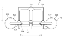
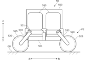
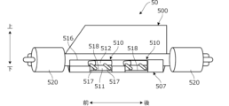
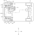
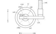
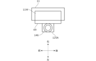
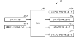
- FIG. 1 is a plan view showing a schematic configuration of a small vehicle on which a vehicle seat according to an embodiment of the present invention is mounted; 1 is a side view showing a schematic configuration of a small vehicle on which a vehicle seat according to an embodiment of the present invention is mounted; FIG. 2 is a perspective view of the passenger seat in FIG. 1 as viewed diagonally from the front left. FIG. 2 is a plan view showing a schematic configuration of the small vehicle in a state in which the auxiliary seat in FIG. 1 is stored; FIG. 1B is a plan view showing a schematic configuration of a small vehicle which is a modified example of FIG. 1A. FIG. 1B is a diagram showing another modified example of FIG. 1A. FIG.
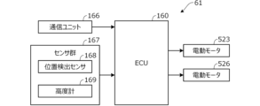
- FIG. 2 is a block diagram showing a control configuration related to a sliding operation of the vehicle seat according to the embodiment of the present invention.
- 1B is a plan view showing an example of a recess provided in a vehicle seat according to an embodiment of the present invention, the example being different from that shown in FIG. 1A .
- FIG. FIG. 6B is a cross-sectional view taken along line VI-VI in FIG. 6A.
- 1 is a side view showing a schematic overall configuration of a swivel seat as a vehicle seat according to an embodiment of the present invention, and shows a position in which the swivel seat is in use.
- FIG. 1 is a plan view showing a schematic overall configuration of a swivel seat as a vehicle seat according to an embodiment of the present invention, and shows a position in which the swivel seat is in use.
- FIG. FIG. 7B is a cross-sectional view taken along line VIII-VIII in FIG. 7A.
- FIG. 7B is a side view showing the non-use position of the swivel seat of FIG. 7A.
- FIG. 7C is a plan view showing the non-use position of the swivel seat of FIG. 7B.
- FIG. 2 is a plan view showing the seat arrangement of a vehicle equipped with a rotating seat.
- FIG. 1 is a perspective view showing a schematic overall configuration of a seat with a vibrator as a vehicle seat according to an embodiment of the present invention
- FIG. 12 is a view taken along line XII of FIG.
- FIG. 13 is a cross-sectional view taken along line XIII-XIII in FIG. 12
- 12A to 12C are diagrams showing an example of the operation of the vibrator-equipped sheet in FIG. 11 .
- FIG. 13 is a diagram showing an example of operation when a magnetic backing having impact hardening properties is used.
- FIG. 1 is a plan view showing a schematic configuration of a passenger transport mode of an aircraft to which a vehicle seat according to an embodiment of the present invention is applied; 1 is a side view showing a schematic configuration of a passenger transport mode of an aircraft to which a vehicle seat according to an embodiment of the present invention is applied.
- 16B is an enlarged view showing a schematic configuration of a main part of the tip of the rotating frame of FIG. 16A.
- FIG. FIG. FIG. 2 is a plan view showing a schematic configuration of the cargo transport mode of the flying object;
- FIG. 2 is a side view showing a schematic configuration of the air vehicle in cargo transport mode.
- FIG. 1 is a diagram showing the schematic configuration of a management system for managing the flight of an aircraft.
- FIG. 4 is a diagram illustrating an example of the operation of an aircraft.
- FIG. 11 is a diagram illustrating another example of the operation of the flying object.
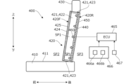
- 1 is a front view showing a schematic configuration of a ventilation adjustable vehicle seat according to an embodiment of the present invention; 24 is a cross-sectional view taken along line A-A in FIG. 23 .
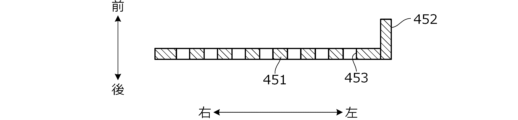
- FIG. 25 is a front view of the front panel of FIG. 24 .
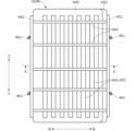
- FIG. 25 is a front view of the rear plate of FIG. 24 .
- FIG. 24 is a front view of the rear portion of the seat back when the linear members constituting the vehicle seat of FIG. 23 are in an unheated state.
- a cross-sectional view taken along line AA in FIG. 27A. 24 is a front view of the rear portion of the seat back in a heated state of the linear members that constitute the vehicle seat of FIG. 23.
- a cross-sectional view taken along line AA in FIG. 28A. 25 is a flowchart showing an example of a process executed by the ECU of FIG. 24 .
- FIG. 1 is a side view showing a schematic configuration of a vehicle seat configured to allow changes in height and inclination angle of a seat cushion
- 1 is a plan view showing a schematic configuration of a vehicle seat configured to allow changes in height and inclination angle of a seat cushion
- FIG. 32 is an enlarged view of a main portion of FIG. 31 .
- 32 is a cross-sectional view taken along line A-A in FIG. 31 .
- FIG. 2 is a block diagram showing a configuration of a control device that controls the operation of the support unit in FIG. 1 .
- FIG. 31 is a side view showing a hip-up position of the vehicle seat of FIG. 30 .
- FIG. 31 is a side view showing the relaxed position of the vehicle seat of FIG. 30 .
- FIG. 31 is a side view showing the vehicle seat of FIG. 30 in a dive-down position.
- 35 is a flowchart showing an example of processing by the ECU of FIG. 34 .
- 35 is a flowchart showing another example of the process performed by the ECU of FIG. 34 .
- 1 is a side view showing a schematic configuration of a vehicle configured so that the seat position can be easily changed.
- 1 is a plan view showing a schematic configuration of a main portion of a front side of a vehicle configured to allow a seat position to be easily changed;
- FIG. 42 is a side view showing an example of a support portion that supports a vehicle seat installed in the vehicle of FIGS. 40 and 41 .
- FIG. 4 is a side view showing a hip-up posture, which is an example of a posture change of the vehicle seat.
- FIG. 11 is a side view showing a relaxed position, which is another example of a position change of the vehicle seat.
- FIG. 42 is a plan view of an operating pedal provided on the vehicle of FIGS. 40 and 41 . A cross-sectional view taken along line BB in FIG. 45A.
- FIG. 42 is a plan view showing a schematic configuration related to the running operation of the vehicle shown in FIGS. 40 and 41 .
- FIG. 42 is a side view of the right front wheel of the vehicle of FIGS. 40 and 41, viewed from the left.
- FIG. 46B is a plan view showing an example in which an in-wheel motor is used instead of the traction motor in FIG. 46A.
- FIG. 47B is a plan view showing a modified example of FIG. 47A.
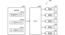
- FIG. 42 is a block diagram showing the configuration of a control device for controlling a seat mode of a seat mounted in the vehicle shown in FIG. 40 and FIG. 41 .
- 1 is a side view of a vehicle showing a state in the middle of changing the seat position from a normal position to a immersed position;
- FIG. 2 is a side view of a vehicle showing an immersion position.
- FIG. 2 is a plan view of the vehicle showing the immersion position.
- FIG. 50C is a plan view of a vehicle showing a modified example of FIG. 50B.
- FIG. 41 is a side view of the vehicle showing the state in which a B-pillar has been added to the vehicle shown in FIG. 40 .
- FIG. 50B is a side view of the vehicle showing the state in which a B-pillar has been added to the vehicle shown in FIG. 50A.
- 1 is a side view showing a schematic configuration of a vehicle seat whose seat position can be changed without using a link mechanism;
- 54 is a perspective view showing a main configuration of a lower slide mechanism included in the support part of FIG. 53 .
- FIG. 54 is a side view showing a schematic configuration of the support part in FIG. 53 .
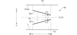
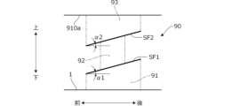
- FIG. 13 is a side view showing a configuration in which a pair of inclined surfaces of the support portion have an upward slope toward the rear.
- FIG. 13 is a side view showing a configuration in which a pair of inclined surfaces of a support portion have a downward slope toward the rear.
- FIG. 54 is a block diagram showing the configuration of a seat control device that controls the operation of the vehicle seat of FIG. 53.
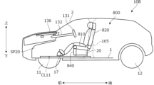
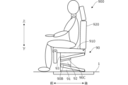
- FIG. 2 is a side view of an example vehicle seat in a raised position.
- FIG. 2 is a side view of an example vehicle seat in a lowered position.
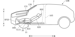
- FIG. 2 is a side view of an example vehicle seat in a forward position.
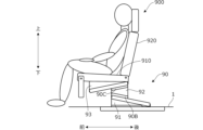
- FIG. 1 is a side view of an example vehicle seat in a relaxed position.
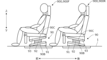
- FIG. 1 is a side view showing an example of a vehicle seat arrangement in two rows, front and rear, each of which is in a normal position;
- FIG. 2 is a side view showing an example of a vehicle seat arranged in two rows, front and rear, each of which is in a relaxed position.
- FIG. 54 is a side view showing a schematic configuration of a main portion of a vehicle on which the vehicle seat of FIG. 53 is mounted.
- FIG. 54 is a front view showing a schematic configuration of a main portion of a vehicle on which the vehicle seat of FIG. 53 is mounted.
- FIG. 63 is a plan view showing an example of a lid for covering the opening of the recess in FIG. 62 .
- FIG. 63 shows a modified example of FIG. 62.
- FIG. 64 shows a modified example of FIG. 63.
- FIG. 67 shows the vehicle seat of FIGS. 65 and 66 with the cyber angle increased.
- the vehicle seat according to the embodiment of the present invention can be applied to various types of vehicles, but below, an example of application to a vehicle, particularly a small vehicle where miniaturization is required, will be described.
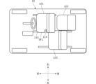
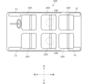
- FIG. 1A is a plan view showing the schematic configuration of a small vehicle 10 on which a vehicle seat 100 according to an embodiment of the present invention is mounted
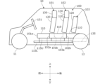
- FIG. 1B is a side view.
- the front-rear direction, left-right direction, and up-down direction are defined as shown in the figure, and the configuration of each part will be explained according to these definitions.
- the front-rear direction, left-right direction, and up-down direction in the figure correspond to the front-rear direction (length direction), left-right direction (width direction), and up-down direction (height direction) of the small vehicle 10, respectively.
- the vehicle seat 100 includes a driver's seat 101 located on the right side of the vehicle interior, a passenger seat 102 located diagonally to the left rear of the driver's seat 101, and an auxiliary seat 103 located behind the driver's seat 101 and to the right of the passenger seat 102 (diagonally to the right rear of the passenger seat 102).
- Figures 1A and 1B also show the configuration of the small vehicle 10, including a pair of left and right front wheels 11 and a pair of left and right rear wheels 12, and a steering wheel 131 installed facing the driver's seat 101.
- the vehicle seat 100 may be simply referred to as the seat 100.
- FIG. 2 is a perspective view (viewed diagonally from the front left) showing the configuration of the passenger seat 102.
- the driver's seat 101 and the passenger seat 102 have roughly the same configuration. Therefore, the configuration of a single seat 100 (driver's seat 101 and passenger seat 102) will be explained using FIG. 1.
- the seat 100 comprises a seat cushion 110 that supports the buttocks of the occupant, a seat back 120 that supports the back of the occupant, and a headrest 130 that is provided on the upper part of the seat back 120 and supports the head of the occupant.
- the seat cushion 110 has a seat cushion frame 111 (only a part of which is shown) that forms the framework of the seat cushion 110.
- the seat cushion frame 111 has, for example, a pair of left and right vertical frames extending in the front-rear direction, and a pair of front and rear horizontal frames that extend in the left-right direction and connect the front ends and rear ends of the pair of left and right vertical frames, respectively, and has a generally rectangular frame shape in a plan view as a whole.
- a generally plate-shaped pressure-receiving member (not shown) is arranged inside the seat cushion frame 111.
- a resilient cushion pad 112 made of, for example, urethane foam material is provided around the seat cushion frame 111, and the surface of the cushion pad 112 is covered with a skin 113.
- the seat back 120 has a seat back frame 121 (only a part of which is shown) that forms the framework of the seat back 120.
- the seat back frame 121 has, for example, a pair of left and right vertical frames extending in a generally vertical direction, and a pair of upper and lower horizontal frames extending in the left and right direction and connecting the upper ends and lower ends of the pair of left and right vertical frames, respectively, and has a generally rectangular frame shape as a whole when viewed from the front.
- a generally plate-shaped pressure-receiving member (not shown) is arranged inside the seat back frame 121.
- a resilient back pad 122 made of, for example, a urethane foam material is provided around the periphery of the seat back frame 121, and the surface of the back pad 122 is covered with a skin 123.
- the lower end of the seat back 120 is supported on the rear end of the seat cushion frame 111 via the reclining mechanism 140 so as to be rotatable in the front-rear direction around a shaft 140a extending in the left-right direction.
- the headrest 130 like the seat back 120, has a headrest frame that forms the skeleton of the headrest 130, a resilient headrest pad provided around the headrest frame, and a skin that covers the surface of the headrest pad.
- a pair of left and right lower rails 115L extending in the fore-aft direction are installed on the upper surface of the floor inside the cabin of the compact vehicle 10.
- a pair of left and right upper rails 115U extending in the fore-aft direction are provided on the bottom of the seat cushion frame 111.
- the upper rails 115U engage with the lower rails 115L, and the seat cushion 110 can slide in the fore-aft direction along the lower rails 115L.
- the upper rails 115U and lower rails 115L are meshed with each other via gears at their engagement portions.
- a slide motor 116 is disposed below the seat cushion 110.
- the rotation of the motor 116 is transmitted, for example, via a shaft to a screw shaft extending along the lower rail 115L, and the rotation of the screw shaft moves a nut along the screw shaft in the front-rear direction, thereby moving the seat cushion 110 in the front-rear direction together with the nut.
- An operation unit (e.g., a switch) 117 operated by a seated person is provided on the side of the seat cushion 110.
- the seated person is sometimes called a user.
- the motor 116 is driven in response to a command to move the seat 100 forward or backward input via the operation unit 117.
- the slide motor 116, the screw shaft, etc. may be omitted, and the user may manually move the seat cushion 110 in the front-rear direction.
- the upper surface of the seat cushion 110 is provided with a seating portion 118 on which the occupant sits, and a pair of left and right banks 119 that bulge upward from the seating portion 118 on both the left and right sides of the seating portion 118 and extend in the front-to-rear direction.
- the buttocks and thighs of the occupant seated on the seat 100 come into contact with the seating portion 118, and the weight of the occupant is mainly supported by the seating portion 118.
- the front surface of the seat back 120 is provided with a seating portion 128 on which the occupant sits, and a pair of left and right banks 129 that bulge forward from the seating portion 128 on both the left and right sides of the seating portion 128 and extend in the up-down direction.
- the seating position of the occupant is regulated by the banks 119, 129.
- the front end surface 102a of the passenger seat 102 is located rearward of the front end surface 101a of the driver's seat 101 and forward of the rear end surface 101b of the driver's seat 101.
- the rear end surface 102b of the passenger seat 102 is located rearward of the front end surface 103a of the auxiliary seat 103.
- the passenger seat 102 is located rearward of the driver's seat 101 and forward of the auxiliary seat 103.
- the auxiliary seat 103 is a simple seat and has a seat cushion 110 and a seat back 120, but the headrest 130 is omitted.
- the auxiliary seat 103 may be provided with a headrest that can be stored compactly, for example, a teardrop-shaped headrest that is approximately L-shaped.
- the length from the left end face SF1 to the right end face SF2 of the seat cushion 110 of the driver's seat 101 is defined as the width of the driver's seat 101.
- the length from the left end face SF3 to the right end face SF4 of the seat cushion 110 of the passenger seat 102 is defined as the width of the passenger seat 102.
- the length from the left end face SF5 to the right end face SF6 of the seat cushion 110 of the auxiliary seat 103 is defined as the width of the auxiliary seat 103.
- the width of the passenger seat 102 is equal to the width of the driver's seat 101
- the width of the auxiliary seat 103 is narrower than the width of the driver's seat 101.
- the width of the auxiliary seat 103 is about 0.8 times the width of the driver's seat 101.
- the left end surface SF5 of the seat cushion 110 of the auxiliary seat 103 is located to the right of the right end surface SF4 of the seat cushion 110 of the passenger seat 102.
- the left end surface SF1 of the seat cushion 110 of the driver's seat 101 is located to the left of the right end surface SF4 of the seat cushion 110 of the passenger seat 102.
- a cutout 114 that is approximately rectangular in plan view is provided on the right end surface SF4 of the seat cushion 110 of the passenger seat 110B, and extends a predetermined length rearward from the front end surface 11b.
- the cutout 114 is provided so as to cut the entire right front corner of the passenger seat 110B (seat cushion frame 111, cushion pad 112, etc.) in the vertical direction.
- the right end surface SF4 of the seat cushion 110 where the cutout 114 is provided i.e., the cutout surface 114a, is located to the left of the left end surface SF1 of the seat cushion 110 of the driver's seat 101. This makes it possible to avoid interference between the driver's seat 101 and the passenger seat 102.
- the cutout 114 is provided in the area of the bank portion 119 at the right front corner of the seat cushion 110. Note that in FIG. 2, the shape of the seat cushion 110 without the cutout 114 is shown by a virtual line (two-dot chain line). Because the cutout 114 is provided in the area in front of the bank portion 119, the seating area 118 does not become narrow, and sufficient seating space can be secured for the occupant of the passenger seat 102.
- three lower rails 115L are installed at equal intervals in the left-right direction on the upper surface of the floor.
- the driver's seat 101 is supported so as to be slidable along the right-end lower rail 115L and the central lower rail 115L.
- the passenger seat 102 is supported so as to be slidable along the central lower rail 115L and the left-end lower rail 115L.
- the central lower rail 115L is used as the lower rail 115L for both the driver's seat 101 and the passenger seat 102. This allows the number of lower rails 115L to be reduced, thereby saving installation space for the lower rails 115L.
- the driver's seat 101 slides forward of the passenger seat 102. Therefore, the front ends of the right and center lower rails 115L, 115L are positioned forward of the front end of the left lower rail 115L.
- the passenger seat 102 slides rearward of the driver's seat 101. Therefore, the rear ends of the center and left lower rails 115L, 115L are positioned rearward of the rear end of the right lower rail 115L. Therefore, there is no need to install a lower rail 115L to the right of the auxiliary seat 103, and the auxiliary seat 103 can be easily positioned without interfering with the lower rail 115L.
- a recess 135 of a predetermined depth is provided in the floor behind the auxiliary seat 103.
- the auxiliary seat 103 can be folded entirely by tilting its seat back 120 forward until it abuts the upper surface of the seat cushion 110, and the entire seat in the folded state can be moved diagonally toward the rear and lower space (recess 135). Alternatively, the entire seat in the folded state can be rotated backward toward the recess 135.
- the recess 135 has a generally box shape corresponding to the shape of the auxiliary seat 103 in the folded state. This allows the auxiliary seat 103 to be stored below the floor.
- Figure 3 is a plan view showing the schematic configuration of the compact vehicle 10 with the auxiliary seat 103 stored in the recess 135. As shown in Figure 3, when the auxiliary seat 103 is stored under the floor, a relatively large, roughly box-shaped space is formed behind the driver's seat 101 and to the right of the passenger seat 102, above the upper surface of the floor. This allows large luggage and the like to be easily loaded into the compact vehicle 10.
- the small vehicle 10 having the vehicle seat 100 is used for traveling relatively short distances such as commuting and shopping. During this type of travel, the passenger often rides alone in the small vehicle 10 and does not carry much luggage. For this reason, it is required to reduce the size of the entire vehicle rather than to expand the space inside the vehicle.
- the passenger seat 102 is disposed diagonally behind the driver's seat 101, and the right end (right end surface SF4) of the passenger seat 102 is positioned to the right of the left end (left end surface SF1) of the driver's seat 101, so that the width of the small vehicle 10 can be narrowed.
- the space inside the vehicle can be kept to a minimum, and a convenient small vehicle 10 is obtained that is easy to use for passengers who often ride alone.
- a notch 114 is provided at the right end of the passenger seat 102 of the compact vehicle 10 to prevent interference with the driver's seat 101.
- the notch 114 is provided only at the right front corner of the seat cushion 110 of the passenger seat 102, so it places little restriction on the passenger space of the passenger seat 102. Therefore, although it is not frequent, it is possible to ensure sufficient comfort for the passenger when sitting in the passenger seat 102.
- auxiliary seat 103 If the auxiliary seat 103 is used, three people can ride in the small vehicle 10.
- the auxiliary seat 103 is constructed more simply and compactly than the other seats 101, 102, but this is not a problem because the auxiliary seat 103 is used even less frequently than the passenger seat 102 and the small vehicle 10 is often used for short distance travel.
- the auxiliary seat 103 can be stored under the floor, so when one or two people ride in the small vehicle 10, the auxiliary seat 103 can be stored to easily transport large luggage.
- FIG. 4A is a plan view showing a schematic configuration of a small vehicle 10 as an example.
- the left end surface SF1 of the seat cushion 110 of the driver's seat 101 is provided with a cutout 114 that is approximately rectangular in plan view from the rear end surface to the front.
- the cutout 114 is provided in the left rear corner of the seat cushion 110 of the driver's seat 101. This makes it possible to prevent interference between the driver's seat 101 and the passenger seat 102.
- Fig. 5 is a block diagram showing the control configuration related to the sliding operation of the seat 100.
- the operating units 117 for the driver's seat and passenger seat are indicated by the reference characters 117A and 117B, respectively, and the motors 116 for the driver's seat and passenger seat are indicated by the reference characters 116A and 116B, respectively.
- signals from operation units 117A, 117B and signals from position sensors 151A, 151B that detect the slide positions of driver's seat 101 and passenger seat 102 are input to ECU 150 (controller) that is composed of a microprocessor and memory.
- ECU 150 controller
- position sensors 151A, 151B various sensors such as a linear encoder, a magnetic sensor (hall sensor), an optical encoder, a potentiometer (variable resistor), a limit switch, and an inclination sensor can be used.
- a sensor that detects the amount of rotation of motors 116A, 116B can also be used as a position sensor.
- Operation units 117A, 117B are, for example, push-type switches, and when operation units 117A, 117B are pushed, a forward command or a reverse command for seats 101, 102 is output, and when the pushing operation stops, the output of the forward command or reverse command stops.
- the ECU 150 When a forward or reverse command for the driver's seat 101 is output by the operation unit 117A, the ECU 150 outputs a control signal to the motor 116A, causing the driver's seat 101 to move forward or backward. Furthermore, when a forward or reverse command for the passenger seat 102 is output by the operation unit 117B, the ECU 150 outputs a control signal to the motor 116B, causing the passenger seat 102 to move forward or backward. At this time, the ECU 150 detects the positions of the driver's seat 101 and the passenger seat 102 based on signals from the position sensors 151A, 151B, and limits the drive of the motors 116A, 116B according to the detected positions.
- the ECU 150 determines whether the driver's seat 110A is in a predetermined forward end position, and if it is determined that the driver's seat 110A is in the forward end position, the ECU 150 stops the forward movement of the driver's seat 101.
- the ECU 150 determines whether the passenger seat 102 is in a predetermined reverse position, and if it is determined that the passenger seat 102 is in the reverse position, the ECU 150 stops the reverse movement of the passenger seat 102.
- the ECU 150 calculates the distance between the driver's seat 101 and the passenger seat 102, more specifically, the distance (seat distance) between the rear end surface 101b of the driver's seat 101 and the end surface 114b (FIG. 1A) of the cutout 114 of the passenger seat 102. Then, it is determined whether the distance between the seats is equal to or less than a predetermined distance, and if it is determined that the distance is equal to or less than the predetermined distance, the reverse movement of the driver's seat 101 or the forward movement of the passenger's seat 102 is stopped. This makes it possible to prevent interference between the driver's seat 101 and the passenger's seat 102.
- the vehicle seat 100 includes a driver's seat 101 having a seat cushion 110 and a seat back 120, and a passenger seat 102 having the seat cushion 110 and the seat back 120 and disposed diagonally to the left rear of the driver's seat 101 (FIGS. 1A and 2).
- a rear end surface 12a of the seat cushion 110 of the driver's seat 101 is positioned rearward of a front end surface 11b of the seat cushion 110 of the passenger seat 102 (FIG. 1B).
- the seat cushion 110 of the driver's seat 101 and the seat cushion 110 of the passenger seat 102 each have a pair of left and right side end surfaces, i.e., a left end surface SF1, a right end surface SF2, and a left end surface SF3, a right end surface SF4 (FIG. 2).
- the left end surface SF1 of the seat cushion 110 of the driver's seat 101 is positioned to the left of the right end surface SF4 of the seat cushion 110 of the passenger seat 102 (FIG. 1A).
- a notch 114 is provided on a right end surface SF4 of the seat cushion 110 of the passenger seat 102 to prevent interference between the driver's seat 101 and the passenger seat 102 (FIGS. 1A and 2).
- the rear left corner of the driver's seat 101 is positioned within the notch 114 at the front right of the passenger seat 102, so the length from the right end surface SF2 of the driver's seat 101 to the left end surface SF3 of the passenger seat 102 can be shortened.
- the vehicle further includes an auxiliary seat 103 located behind the driver's seat 101 and to the right of the right end surface SF4 of the passenger seat 102 (FIG. 1A). This allows three people to ride in the small vehicle 10.
- the width of the auxiliary seat 103 in the left-right direction is narrower than the width of the driver's seat 101 in the left-right direction (FIG. 1A). By narrowing the width of the auxiliary seat 103, which is used less frequently, in this manner, the auxiliary seat 103 can be properly positioned so as not to interfere with the driver's seat 101 and the passenger seat 102.
- the floor of the small vehicle 10 in which the auxiliary seat 103 is installed is provided with a recess 135 in which the auxiliary seat 103 can be stored when not in use (FIGS. 1A and 1B). This allows the auxiliary seat 103 to be stored under the floor, creating a large space behind the driver's seat 101 and to the right of the passenger seat 102.
- the vehicle seat 100 further includes a pair of left and right lower rails 115L that extend in the front-rear direction on the upper surface of the floor of the small vehicle 10 and support the driver's seat 101 so that it can move in the front-rear direction, and a pair of left and right lower rails 115L that extend in the front-rear direction on the upper surface of the floor and support the passenger seat 102 so that it can move in the front-rear direction (Figs. 1A and 2).
- the left lower rail 115L for the driver's seat and the right lower rail 115L for the passenger seat are the same, and the lower rail 115L is shared (Fig. 1A). This allows the number of lower rails 115L to be reduced, the width of the small vehicle 10 in the left-right direction to be narrowed, and costs to be reduced.
- the driver's seat 101 is configured as a first seat having a seat cushion 110 (first seat cushion) and a seat back 120 (first seat back)
- the passenger seat 102 is configured as a second seat having a seat cushion 110 (second seat cushion) and a seat back 120 (second seat back)
- the first seat may be other than the driver's seat
- the second seat may be other than the passenger seat.
- the second seat may be disposed diagonally rearward to the right instead of diagonally rearward to the left of the first seat.
- the driver's seat 101 and the passenger seat 102 are slid forward and backward by driving the motor 116, but the motor 116 may be omitted and the driver's seat 101 and the passenger seat 102 may be moved forward and backward manually.
- a stopper that limits the movement of the driver's seat 101 rearward from a predetermined position e.g., the position in FIG. 1A
- a stopper that limits the movement of the passenger seat 102 forward from a predetermined position e.g., the position in FIG. 1A
- a notch 114 is provided in the front end portion (FIG. 1A) of the right end surface SF4 (second side end portion) of the passenger seat 102 or the rear end portion (FIG. 4A) of the left end surface SF1 (first side end portion) of the driver's seat 101, but other relief portions may be provided to prevent interference between the first side end portion and the second side end portion.
- FIG. 6A is a plan view showing another example of a relief portion
- FIG. 6B is a cross-sectional view taken along line VI-VI in FIG. 6A.
- FIG. 6A shows the left rear corner portion CR1 of the seat cushion 110 of the driver's seat 101 and the right front corner portion CR2 of the seat cushion 110 of the passenger seat 102.
- a generally rectangular recess 1141 of a predetermined depth is provided on the bottom surface of the left rear corner CR1 of the driver's seat 101.
- a generally rectangular recess 1142 of a predetermined depth is provided on the top surface of the right front corner CR2 of the passenger seat 102.
- the lower corner CR2 of the recess 1142 of the passenger seat 102 is positioned in the recess 1141 of the driver's seat 101
- the upper corner CR1 of the recess 1141 of the driver's seat 101 is positioned in the recess 1142 of the passenger seat 102.
- a recess 1141 may be provided on the top surface of corner CR1, and a recess 1142 may be provided on the bottom surface of corner CR2, reversing the up-down relationship of corners CR1 and CR2.
- seats 101 and 102 may be positioned so that the left end (first side end) of driver's seat 101 is located above or below the right end (second side end) of passenger seat 102, thereby forming a relief portion.
- the auxiliary seat 103 is disposed as the third seat behind the driver's seat 101 and to the right of the passenger seat 102, but the configuration of the third seat is not limited to that described above.
- the third seat may be a net seat in which an elastic net material is stretched over the seat surface and the cushion pad 112 and back pad 122 are omitted.
- the auxiliary seat 103 can be stored in the recess 135 in the floor, but the recessed storage portion does not have to be provided.
- the third seat may be a flip-up type seat that is flipped up to the right for storage, for example.
- the driver's seat 101 is slidably supported by a pair of left and right lower rails 115L (rails for the first seat) provided at the right end and center of the small vehicle 10
- the passenger seat 102 is slidably supported by a pair of left and right lower rails 115L (rails for the second seat) provided at the left end and center. That is, a part of the multiple lower rails 115L supporting the driver's seat 101 (left lower rail 115L) and a part of the multiple lower rails 115L supporting the passenger seat 102 (right lower rail 115L) are shared, but the driver's seat 101 and the passenger seat 102 may each be supported by separate rails. For example, as shown in FIG.
- the pair of left and right lower rails 115L supporting the driver's seat 101 and the pair of left and right lower rails 115L supporting the passenger seat 102 may be provided separately.
- a notch 114 may be provided in the seat cushion 110 of the driver's seat 101 as shown in FIG. 4A.
- Each seat 101, 102 may be supported by three or more rails.
- a vehicle seat 100 including a driver's seat 101 (first seat) and a passenger seat 102 (second seat) has been described, but the present invention can also be configured as a small vehicle including a first seat and a second seat. Therefore, the configuration can be rewritten from a vehicle seat to a small vehicle.
- the seat when comparing a vehicle seat (seat) when in use with an occupant seated and when not in use with no occupant seated, it is preferable to make the seat narrower when not in use than when in use in order to expand the effective space within the vehicle cabin. It is even more preferable to narrow the seat width and configure the entire seat to be rotatable around an axis extending in the vertical direction, as this allows the orientation of the seat to be easily changed without interfering with other components around the seat or other occupants. Taking this into consideration, in this embodiment, the seat is further configured as follows. Note that hereinafter, the seat may be referred to as a swivel seat.
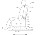
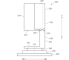
- FIG. 7A is a side view showing a schematic overall configuration of the rotating seat 200
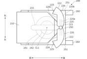
- FIG. 7B is a plan view.
- the rotating seat 200 is mounted on a vehicle (not shown).
- the vehicle may be the above-mentioned small vehicle 10, or may be a vehicle other than a small vehicle.
- the rotating seat 200 can also be mounted on a vehicle other than a vehicle.
- FIGS. 7A and 7B show the usage posture of the rotating seat 200 in which an occupant can be seated.
- the swivel seat 200 has a seat cushion 210 that supports the buttocks of the occupant PS, a seat back 220 that supports the back of the occupant PS, and a support frame 230 that supports the seat cushion 210 and the seat back 220.
- the support frame 230 is supported by a base member 250 that is a plate-like member that is generally rectangular in plan view, via a rotation device 240.
- a pair of left and right upper rails 251 are provided on the bottom of the base member 250.
- the upper rails 251 are slidably engaged with a pair of left and right lower rails 260 that are installed on the upper surface of the vehicle floor and extend in the fore-and-aft direction.
- the rotation device 240 has an outer tube portion 241 that is generally cylindrical and centered on an axis line CL1 that extends in the vertical direction and is fixed to the upper surface of the base member 250, and an inner tube portion 242 that is generally cylindrical and centered on the axis line CL1 and is disposed inside the outer tube portion 241.
- the inner tube portion 242 is supported by the outer tube portion 241 so as to be rotatable about the axis line CL1.
- the support frame 230 has a rod- or pipe-shaped horizontal frame 231 that extends in the front-rear direction through the center (axis line CL1) of the rotation device 240, and a rod- or pipe-shaped vertical frame 232 that rises from the rear end of the horizontal frame 231. Therefore, the support frame 230 as a whole has a roughly L-shape when viewed from the side.
- the horizontal frame 231 is fixed to the inner cylinder portion 242 of the rotation device 240 and rotates integrally with the inner cylinder portion 242. Both front-rear end portions of the horizontal frame 231 are located further inward in the front-rear direction than both front-rear end portions of the base member 250.
- the seat back 220 has a generally pipe-shaped central frame 221 that extends vertically in the left-right center, and a pair of left and right split seat backs 222 arranged on the left and right sides of the central frame 221.
- the split seat back 222 has a rotating frame 220a that forms the skeleton of the split seat back 222.
- the left-right inner end of the rotating frame 220a is rotatably supported by the central frame 221.
- a back pad 220b is provided around the rotating frame 220a, and the surface of the back pad 220b is covered with a skin 220c.
- Figure 7B shows the state in which the split seat backs 222 have been rotated to the maximum extent outward (rearward) in the left-right direction, with the central frame 221 as the fulcrum.
- the rear surfaces 226 of the left and right split seat backs 222 are formed in a substantially arc shape in a plan view so that when the split seat backs 222 are rotated inward in the left-right direction from the state in Figure 7B, they become substantially semicircular overall (see Figure 9B).
- the seating surface 224 on the front side of the seat back 220 extends in a substantially straight line in the left-right direction.
- the rear surface 226 of the seat back 220 protrudes rearward beyond the central frame 221.
- a bank portion 225 is provided at the outer left-right end of the seat back 220.
- FIG. 7A shows a reclining position in which the seat back 220 is tilted backward by a predetermined tilt angle ⁇ .
- FIG. 7B shows a state in which the tilt angle ⁇ is 0°.
- the tilt angle ⁇ is 0°
- the seating surface 224 extends along a vertical plane.
- FIG. 8 is a cross-sectional view taken along line VIII-VIII in FIG. 7A.
- the seat cushion 210 has a seat cushion frame 210a that forms the skeleton of the seat cushion 210.
- a cushion pad 210b is provided around the seat cushion frame 210a, and the surface of the cushion pad 210b is covered with a skin 210c.
- a substantially horizontal seating surface 214 is formed on the upper surface of the seat cushion 210.
- Bank portions 215 are provided on the outer ends of the seat cushion 210 in the left and right directions.
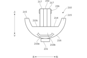
- a bottom surface 216 of the seat cushion 210 is substantially semicircular and protrudes downward.
- the left-right center of the bottom surface 216 of the seat cushion 210 is mounted on the upper surface of a horizontal frame 231.
- the seat cushion 210 has a pair of left and right pillars 217 extending upward from its rear end.
- the front end of a vertical frame 232 is interposed between the left and right pillars 217.
- the upper end of the pillar 217 is supported on the upper end of the vertical frame 232 so as to be rotatable up and down around a pivot shaft 236 extending left and right.
- the swivel seat 200 can be changed from a use position (Figs. 7A and 7B) in which an occupant can sit to a non-use position in which an occupant cannot sit.
- a use position Figs. 7A and 7B
- both left and right ends of the seat back 220 protrude outward in the left and right direction beyond both left and right ends of the base member 250. This allows the left and right width of the seating surface 224 of the seat back 220 to be increased.
- both left and right ends of the seat cushion 210 are located laterally inward in the left and right direction beyond both left and right ends of the base member 250.
- FIG. 9A is a side view of the swivel seat 200 in the non-use position
- FIG. 9B is a plan view.
- the tilt angle ⁇ (FIG. 7B) of the seat back 220 is 0°
- the rear end surface of the central frame 221 is located on an extension line of the rear end surface of the vertical frame 232.
- the seat cushion 210 is rotated upward by 90° around the rotation shaft 236 as a fulcrum, and the bottom surface 216 of the seat cushion 210 extends vertically.
- the seat back 220 is always biased to the non-use position by, for example, the biasing force of a spring.
- the seat back 220 has a locking mechanism that holds the seat back 220 in the use position against the biasing force of the spring. Therefore, when the locking mechanism is released in the use position, the seat back 220 is biased to the non-use position by the biasing force of the spring.
- the pair of left and right split seat backs 222 are rotated inward in the left-right direction, and the right end surface 222c of the left split seat back 222 and the left end surface 222c of the right split seat back 222 abut against each other. This limits the maximum rotation amount of the split seat backs 222.
- the rear surface 226 of the seat back 220 has an approximately semicircular shape centered on the axis CL1.
- the bottom surface 216 of the seat cushion 210 also has an approximately semicircular shape that is shaped along the axis CL1.
- the front end surface of the bank portion 225 of the seat back 220 and the rear end surface of the bank portion 215 of the seat cushion 210 come into contact.
- the rear surface 226 of the seat back 220 and the bottom surface 216 of the seat cushion 210 as a whole form a roughly cylindrical shape centered on the axis line CL1 in a plan view.
- the diameter of the cylindrical surface centered on the axis line CL1 is approximately equal to the length of the horizontal frame 231 in the front-rear direction, and the entire cylindrical surface is located inside both left-right and front-rear end portions of the base member 250. Therefore, the entire seat cushion 210 and the seat back 220 can be efficiently arranged in the inner space of a predetermined cylindrical surface centered on the axis line CL1.
- the rotation of the swivel seat 200 is prevented by a locking mechanism (not shown). This allows the swivel seat 200 to be fixed in the use position shown in Figures 7A and 7B.
- the user passesenger first releases the locking mechanism. Then, the seat back 220 is rotated forward around the rotation shaft 235 as a fulcrum, the seat back 220 is raised with the tilt angle ⁇ set to 0°, and the pair of left and right split seat backs 222 are rotated inward in the left-right direction via the central frame 221. Furthermore, the user rotates the seat cushion 210 upward around the rotation shaft 236 as a fulcrum, and the seat cushion 210 is raised.
- the user rotates the swivel seat 200 by 180° via the rotation device 240 to activate the locking mechanism.
- the entire seat cushion 210 and seat back 220 of the swivel seat 200 are disposed inside a cylindrical surface of a predetermined radius centered on the axis CL1. Therefore, the amount of radially outward protrusion of the swivel seat 200 is small, and the user can easily rotate the swivel seat 200 without interfering with surrounding members or occupants.
- the space required for the rotation of the swivel seat 200 is determined by the distance from the axis CL1 to the radially outermost portion.
- the radially outermost portion (the bottom surface 216 of the seat cushion 210 and the rear surface 226 of the seat back 220) is located on a cylindrical surface centered on the axis CL1, so that the distance from the axis CL1 to the radially outermost portion can be shortened.
- the user rotates the left and right split seat backs 222 outward in the left and right direction and rotates the seat cushion 210 downward. This allows the rotating seat 200 to be positioned backwards for use.
- Activation and release of the locking mechanism, rotation of the seat cushion 210 about the pivot axis 236, rotation of the seat back 220 about the pivot axis 235, rotation of the split seat back 222 with the central frame 221 as the fulcrum, and rotation of the swivel seat 200 about the axis CL1 can each be performed manually. Any one, several, or all of these operations may be performed by driving an actuator such as a motor. For example, the actuator may be driven in response to a switch operation by the user.
- the rotating seat 200 as a vehicle seat can be transformed from a use position where an occupant can sit to a non-use position where an occupant cannot sit (FIGS. 7A and 9A).
- the seat back 220 is configured so that the width of the seat back 220 in the non-use position is narrower than the width of the seat back 220 in the use position (FIGS. 7B and 9B). This can increase the available space in the vehicle cabin when the rotating seat 200 is not in use.
- the seat cushion 210 is further provided with a rotation device 240 that supports the seat cushion 210 so that the seat cushion 210 can rotate about an axis CL1 that extends vertically (FIG. 7A). This allows the orientation of the swivel seat 200 to be easily changed even when the width of the seat back 220 is narrowed.
- the swivel seat 200 further includes a support frame 230 that rotatably supports the seat cushion 210 so that the seat cushion 210 stands upright in the non-use position (FIGS. 7A and 9A).
- the seat cushion 210 and the seat back 220 each have a seating surface 214, 224 on which an occupant sits, and a back surface (bottom surface 216 and rear surface 226) opposite the seating surface 214, 224 (FIGS. 7B and 8).
- the distance from the axis CL1 to the rear surface 226 of the seat back 220 and the distance to the bottom surface 216 of the seat cushion 210 are approximately equal (FIG. 9B). This allows the diameter of the swivel seat 200 about the axis CL1 in the non-use position to be reduced, allowing the swivel seat 200 to rotate in a narrow space.
- the rear surface 226 of the seat back 220 and the bottom surface 216 of the seat cushion 210 are configured to have a generally arcuate shape so as to extend along a cylindrical surface centered on the axis line CL1 in the non-use position (FIG. 9B). This allows the diameter of the swivel seat 200 centered on the axis line CL1 in the non-use position to be minimized, and the space required for rotation of the swivel seat 200 to be minimized.
- the seat back 220 has a central frame 221 that extends in a generally vertical direction, and a pair of split seat backs 222 that are rotatable inward in the width direction around the central frame 221 (FIG. 9B). This allows the width of the seat back 220 to be easily narrowed when the swivel seat 200 is not in use.
- the support frame 230 has a vertical frame 232 that extends in the up-down direction near the rear end of the seat cushion 210, and a rotating shaft 236 provided at the upper end of the vertical frame 232 (Figs. 7A and 9A).
- the seat cushion 210 is supported so as to be rotatable in the up-down direction via the rotating shaft 236 (Figs. 7A and 9A). This allows the seat cushion 210 to stand upright, and the distance from the axis CL1 to the end of the seat cushion 210 can be shortened.
- the seat back 220 is configured with a central frame 221 (rotating shaft) and a pair of left and right split seat backs 222 (back rotating parts), but the configuration of the seat back 220 is not limited to the above. In other words, the seat back 220 may have any configuration as long as the width of the seat back 220 in the non-use position is narrower than the width of the seat back 220 in the use position. In the above embodiment, both left and right ends of the seat back 220 are arranged to be rotatable in the left and right direction, but both left and right ends of the seat cushion 210 may be arranged to be rotatable in the left and right direction in the same manner.
- the seating surface 214 of the seat cushion 210 becomes a substantially horizontal plane
- the bottom surface 216 of the seat cushion 210 becomes a substantially arcuate shape (FIG. 8).
- the seat cushion 210 is rotatably supported by a support frame 230 serving as a seat cushion support part.
- the seat cushion 210 is supported rotatably in the vertical direction via a horizontally extending rotation shaft 236 (horizontal shaft) at the upper end of a vertical frame 232 (vertical part) extending in the vertical direction near the rear end of the seat cushion 210, but the seat cushion support part may have any configuration as long as it rotatably supports the seat cushion so that the seat cushion 210 stands upright in the non-use position.
- the horizontal frame 231 is configured to be elongated in the front-rear direction, but the horizontal frame may be expanded in the left-right direction, and a seat belt attachment part may be provided at the left-right end of the horizontal frame.
- the distance from the axis CL1 to the bottom surface 216 (back surface) on the opposite side of the seating surface 214 of the seat cushion 210 is equal to the distance to the rear surface 226 (back surface) on the opposite side of the seating surface 224 of the seat back 220. More specifically, the back surface of the seat cushion 210 and the back surface of the seat back 220 extend along a cylindrical surface centered on the axis CL1, but the distance from the axis CL1 to the back surface of the seat cushion 210 and the distance to the back surface of the seat back 220 may be different.
- FIG. 10 is a plan view showing an example of a vehicle 10A on which the rotating seat 200 is mounted.
- the vehicle 10A of FIG. 10 has three rows of seats in the front-rear direction.
- the rotating seat 200 is applied to, for example, the second row seats, and normal seats 100 (non-rotating seats) are arranged in the first and third rows. This allows the occupants of the second row seats and the third row seats to sit facing each other.
- the rotating seat 200 may be changed from the use position to the non-use position not only when changing the orientation of the rotating seat 200 but also when loading luggage into the vehicle interior. This increases the space for loading luggage in the vehicle interior, making it easier to load luggage.
- the rotating seat 200 may be changed from the use position to the non-use position. This makes it easier for an occupant to get into the rear seat. In the non-use position, if necessary, only the seat back 220 of the rotating seat 200 may be rotated inward without rotating the seat cushion 210 upward.
- the vehicle seat according to this embodiment can be configured to have the function of notifying information without using voice or the like. Specifically, it can be configured to notify predetermined information to occupants by applying vibrations to the occupants via the seat. If information is notified by voice or the like, there is a risk that communication with passengers may be interrupted if there are passengers in the vehicle. In this regard, by notifying information by applying vibrations, the occupant (e.g. the driver) can recognize the predetermined information without interrupting communication with the passengers.
- Examples of the specified information include approach information indicating that the approach of another vehicle has been detected while driving, erroneous operation information indicating that the driver has performed an erroneous operation while driving, a charging completion notification indicating that battery charging has been completed in EV driving mode, and caution information to alert the driver when driving through an intersection or crosswalk.
- the vibration may be applied to the driver for purposes other than reporting information, such as waking the driver up from drowsiness, or vibration may be applied to passengers other than the driver. Below, a seat configured to provide vibration to passengers is described.
- FIG. 11 is a perspective view showing a schematic configuration of a seat with a vibrator 300 as a vehicle seat according to an embodiment of the present invention.
- the seat with a vibrator 300 includes a seat cushion 310 that supports the buttocks of the occupant, a seat back 320 that supports the back of the occupant, and a headrest 330 that is provided on the upper part of the seat back 320 and supports the head of the occupant.
- the seat 300 with a vibrator has the same configuration as the seat 100 shown in FIG. 2. That is, the seat cushion 310 has a seat cushion frame 311 (only a part of which is shown) that forms the skeleton of the seat cushion 310, a cushion pad 312 provided around the seat cushion frame 311, and a skin 313 that covers the surface of the cushion pad 312.
- the seat back 320 has a seat back frame 321 (only a part of which is shown) that forms the skeleton of the seat back 320, a back pad 322 provided around the seat back frame 321, and a skin 323 that covers the surface of the back pad 322.
- the headrest 330 has a headrest frame that forms the skeleton of the headrest 330, a resilient headrest pad provided around the headrest frame, and a skin that covers the surface of the headrest pad.
- the seat back 320 is provided with a plurality of vibration units 350 each having a vibrator.
- a pair of left and right vibration units 350 is provided above and below the seating portion 328, which is inside the left and right bank portions 329 of the seat back 320.
- the pair of upper left and right vibration units 350 is disposed laterally outboard of the pair of lower left and right vibration units 350.
- the vibration units 350 are provided, for example, in correspondence with the position of the latissimus dorsi of the occupant.
- the number and installation positions of the vibration units 350 are not limited to those shown in the figure, so long as they are provided in a position where the seated occupant can easily feel vibration.
- the vibration units 350 may be provided in the seat cushion 310 instead of or in addition to the seat back 320.
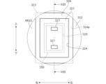
- FIG. 12 is a front view (arrow XII view in FIG. 11) of the seating portion 328 of the seat back 320 where the vibration unit 350 is provided, as seen from the front, and FIG. 13 is a cross-sectional view taken along line XIII-XIII in FIG. 12.
- FIG. 12 shows a part of the skin 323 cut into an approximately circular shape (area AR10).
- the front surface of the back pad 322 is provided with a recess 324 of a predetermined depth and a generally rectangular shape in front view, and further provided at the back of the recess 324 is a recess 325 of a predetermined depth and a generally rectangular shape in front view.
- the front surface of the back pad 322 is provided with stepped recesses 324, 325.
- the recess 325 is provided inside the recess 324, and the bottom surface 324a of the recess 324 is formed to extend vertically all around the recess 325.
- a vibration unit 350 is placed in the recess 325.
- the vibration unit 350 has a vibration unit case 351 (shown by a thick line for convenience) formed in a roughly box-like shape corresponding to the shape of the recess 325, and a vibration actuator 352 and a vibrator 353 placed inside the vibration unit case 351.
- the vibrator 353 is fixed to the front surface of the vibration actuator 352.
- the vibration actuator 352 is a linear vibration actuator that receives an electrical signal and causes the vibrator 353 to reciprocate up and down (in the direction of the arrow in FIG. 13).
- a pair of upper and lower permanent magnets 356 are fixed to the front of the vibrator 353.
- the front and rear of the permanent magnet 356 are, for example, a north pole and a south pole.
- the front of the permanent magnet 356 is positioned with a gap from the opposing vibration unit case 351 so that the permanent magnet 356 can move smoothly within the vibration unit case 351.
- the front of the vibration unit case 351 may be left open.
- FIGs 12 and 13 show the state before the vibrator 353 vibrates, at which time the vibrator 353 is located at the middle position in the up-down direction.
- a lid pad 326 which is part of the back pad 322, is placed in the recess 324.
- the lid pad 326 has a roughly rectangular plate shape and is made of the same material as the back pad 322 (e.g., urethane foam material).
- the overall thickness (length in the front-to-rear direction) of the lid pad 326 is the same as the depth of the recess 324, and the lid pad 326 is interposed between the skin 323 and the bottom surface 324a of the recess 324 of the back pad 322.
- the lid pad 326 is foam-molded together with a magnetic mount 357 to which a pair of upper and lower permanent magnets 327 are fixed.
- the magnetic mount 357 is made of a material that hardens reversibly upon impact, specifically, a sheet-like material with impact hardening properties in which the molecules bond with each other and harden when an impact is received, and then return from the hardened state to its original state when the impact is removed.
- the permanent magnet 356 on the vibrator side and the permanent magnet 327 on the skin side have approximately the same shape in a plan view.
- the permanent magnet 327 on the skin side is located at the same position in the front-to-back and left-to-right directions as the permanent magnet 356 on the vibrator side, at the intermediate position in Figs. 12 and 13, and is located a predetermined distance (e.g., approximately 10 mm) forward from the permanent magnet 356.
- the front and rear surfaces of the permanent magnet 327 on the skin side are, for example, north and south poles corresponding to the permanent magnet 356 on the vibrator side.
- the magnetic force (attraction force) that attracts the permanent magnets 356, 327 to each other is greatest when the vibrator 353 is located at the intermediate position, and the attraction force decreases as the vibrator 353 moves up and down from the intermediate position.
- an ECU 370 having a microcomputer and memory is connected to the vibration actuator 352.
- Signals are input to the ECU 370 from various sensors 371 (camera, radar, lidar, etc.) that detect or sense, for example, the conditions around the vehicle and the conditions inside the vehicle cabin.
- the ECU 370 determines whether or not it is necessary to notify an occupant (for example, the driver) of specific information (for example, the approach of another vehicle). Then, when it is determined that it is necessary to notify the specific information, the ECU 370 outputs a control signal to the vibration actuator 352, causing the vibrator 353 to vibrate.
- the ECU 370 outputs a control signal to the vibration actuator 352 and vibrates the vibrator 353 until it is determined that it is no longer necessary to notify the specified information (for example, until it is determined that the driver has recognized the approach of another vehicle). When it is determined that it is no longer necessary to notify the specified information, the ECU 370 stops the vibration of the vibrator 353. Note that when it is determined that it is necessary to notify the specified information, the ECU 370 may vibrate the vibrator 353 for only a specified period of time.
- FIG. 14 is a diagram showing an example of the operation of the sheet with vibrator 300.
- the vibrator 353 when the vibrator 353 is in the intermediate position, the permanent magnet 327 on the surface side is attracted by the permanent magnet 356 on the vibrator side. This causes the magnetic mount 357 and the lid pad 326 to elastically deform, and the permanent magnet 327 moves backward.
- a downward attractive force acts on the permanent magnet 327 on the surface side. This attractive force becomes smaller as the distance between the permanent magnets 356 and 327 increases.
- the permanent magnet 327 on the surface side moves further forward than when the vibrator 353 is in the intermediate position, due to the elastic force of the magnetic mount 357 and the lid pad 326 trying to return to their original positions.
- the attractive force acting on the permanent magnet 327 on the skin side gradually increases as the distance between the permanent magnets 356, 327 decreases. Then, when the vibrator 353 rises to the neutral position, the attractive force reaches its maximum, and the permanent magnet 327 on the skin side moves backward. When the vibrator 353 further rises from the neutral position, an upward attractive force acts on the permanent magnet 327 on the skin side. This attractive force decreases as the distance between the permanent magnets 356, 327 increases. As a result, at the raised position where the vibrator 353 has risen to its maximum, the permanent magnet 327 on the skin side moves further forward than when the vibrator 353 is in the neutral position.
- the permanent magnet 327 on the skin side reciprocates in the front-to-rear direction as the vibrator 353 moves up and down. This causes vibrations to be applied to the occupant via the magnet mount 357 and the skin 323. If the permanent magnet 327 is placed on the surface of the seat, the occupant will feel a strange sensation as if there is a foreign object on the surface of the seat, but by placing the permanent magnet 327 on the back side of the skin 323, the occupant is less likely to feel the discomfort.
- the permanent magnet 327 is placed further back than the back side of the skin 323, the occupant will be less likely to feel the vibration, but since the permanent magnet 327 is fixed to the magnet mount 357 on the back side of the skin 323, the occupant will be more likely to feel the vibration, and information can be transmitted to the occupant well.
- the magnet mount 357 is made of a material that has impact hardening properties. Therefore, as shown diagrammatically in FIG. 15, when the vibrator 353 is in the neutral position, the area of elastic deformation of the magnet mount 357 increases. In other words, when the magnet mount 357 is made of a material that does not have impact hardening properties, the magnet mount 357 deforms locally as shown by the dotted line in FIG. 15, whereas when it is made of a material that has impact hardening properties, the range of deformation of the magnet mount 357 is large as shown by the solid line in FIG. 15.
- the area of deformation AR11 (solid line) when the magnet mount 357 is made of a material that has impact hardening properties is larger than the area of deformation AR12 (dotted line) when it is made of a material that does not have impact hardening properties.
- the passenger is more likely to feel the vibration.
- a seat with a vibrator 300 as a vehicle seat includes a vibration actuator 352 that drives a vibrator 353 built into a seat back 320, a skin 323 that forms a seating surface on which a user sits, a permanent magnet 327 arranged on the back side of the skin 323, and a permanent magnet 356 that is attached to the surface of the vibrator 353 and vibrates when driven by the vibration actuator 352 (FIGS. 11 to 13).
- the permanent magnet 356 on the vibrator side is arranged within a range where it interacts with the permanent magnet 327 on the skin side (FIG. 14).
- the vibrator-equipped sheet 300 further includes a back pad 322 provided on the back side of the skin 323 (FIG. 11).
- the back pad 322 has a recess 325 recessed from the surface of the back pad 322 facing the skin 323, and a lid pad 326 covering the recess 325 (FIG. 13).
- the vibration actuator 352 and the permanent magnet 356 on the vibrator side are disposed in the recess 325, and the permanent magnet 327 on the skin side is disposed on the lid pad 326 (FIG. 13). This allows the permanent magnet 356 to easily reciprocate up and down within the recess 325, and the permanent magnet 327 on the skin side can be vibrated well in accordance with the reciprocating motion of the permanent magnet 356.
- the cover pad 326 has a sheet-like magnetic mount 357 made of a material that hardens reversibly when subjected to vibration, and the permanent magnet 327 on the surface side is placed on the magnetic mount 357 ( Figure 13). As a result, when the permanent magnet 327 is vibrated, the magnetic mount 357 hardens, expanding the vibration area and making it easier to transmit the vibration to the occupant.
- the seat with vibrator 300 further includes an ECU 370 as a control unit that controls the vibration actuator 352 (FIG. 13).
- ECU 370 When the ECU 370 needs to notify the user of certain information, it outputs a control signal to drive the vibration actuator 352. This allows the information to be effectively notified to the user by applying vibrations.
- a pair of upper and lower permanent magnets 327 are arranged on the back side of the skin 323, but the number and arrangement of the first permanent magnets are not limited to those described above. For example, there may be only one first permanent magnet. However, if there are multiple first permanent magnets, it is easier to transmit vibrations to the occupant.
- the same number of permanent magnets 356 (second permanent magnets) as the permanent magnets 327 are arranged on the inside of the back pad 322 in correspondence with the permanent magnets 327 on the skin side, but the number and arrangement of the second permanent magnets are not limited to those described above.
- the number of first permanent magnets and the number of second permanent magnets do not have to be the same. In other words, the arrangement of the second permanent magnets may be any, as long as they are arranged within a range where they interact with the first permanent magnets.
- the back pad 322 (seat pad) provided on the back side of the skin 323 of the seat back 320 is provided with the recess 325 and the lid pad 326 (lid portion) that covers the recess 325, but these may also be provided on the cushion pad 312 provided on the back side of the skin 313 of the seat cushion 310.
- a linear vibration actuator 352 that moves the vibrator 353 back and forth in the vertical direction is provided as the vibration actuator, but the configuration of the vibration actuator is not limited to this.
- the magnetic mount 357 (planar structure) made of a material that hardens reversibly when subjected to vibration is provided on the lid pad 326, but the material of the planar structure is not limited to this.
- the ECU 370 as the control unit when notifying the user of specific information, the ECU 370 as the control unit outputs a control signal to drive the vibration actuator 352, but the specific information includes various information to be notified to the driver and passengers other than the driver.
- the vibration pattern may be changed depending on the type of information to be notified to the passengers.
- the vehicle seats 100, 200, 300 described above can be applied not only to vehicles, but also to vehicles other than vehicles, such as aircraft and ships.
- the vehicle seats 200, 300 can be modified to become the vehicle seat 100 of FIG. 1A. That is, of the pair of left and right side ends of the pair of left and right vehicle seats 200, 200, the end face of the side end (first side end) on the other side in the left and right direction (e.g. left side) of the seat cushion 210 of the seat 200 on one side in the left and right direction (e.g. right side) is located on one side in the left and right direction (e.g. left side) than the end face of the side end (second side end) on one side in the left and right direction (e.g.
- the end face of the side end (first side end) on the other side in the left-right direction (e.g. left side) of the seat cushion 310 of the seat 300 on one side in the left-right direction (e.g. right side) may be located on one side in the left-right direction (e.g.
- the vehicle seat according to the embodiment of the present invention can also be applied to an aircraft.
- an aircraft to which the vehicle seat according to the embodiment of the present invention can be applied will be described with reference to Figures 16A to 22B.
- the aircraft according to the embodiment can fly unmanned without a pilot on board, receiving commands from outside via a communication unit.
- This aircraft is configured so that the internal space can be switched between a people transport mode for transporting people, and a cargo transport mode for transporting cargo.
- People transported in the people transport mode i.e., passengers, include passengers who pay a fare to board, and crew members who board without paying a fare. Below, for convenience, it is assumed that passengers are transported in the people transport mode.
- FIG. 16A is a plan view showing a schematic configuration of an aircraft 50 to which a vehicle seat according to an embodiment of the present invention is applied
- FIG. 16B is a side view.
- the three mutually orthogonal axial directions as shown in the figure are defined as the front-to-rear direction (length direction), left-to-right direction (width direction), and up-to-down direction (height direction) of the aircraft 50, and the configuration of each part will be explained according to these definitions.
- the height direction corresponds to the direction of gravity.
- FIGS. 16A and 16B show the state of the aircraft 50 flying in human transport mode.
- the aircraft 50 has an aircraft body 500 that constitutes a cabin 500a, and a number of propulsion devices 520 provided around the aircraft body 500.
- the aircraft body 500 has a bottom surface 501, a top surface 502, a front surface 503, a rear surface 504, and a pair of left and right side surfaces 505, and the cabin 500a, which is roughly rectangular, is formed inside these surfaces 501 to 505.
- the front surface 503, rear surface 504, and side surfaces 505 can be made partially or entirely of transparent glass.
- an openable door is provided on the side surface 505 to allow passengers to board the aircraft body 500.
- the aircraft body 500 has frame members that form the framework of the aircraft body 500, and cover members that cover the periphery of the frame members. Batteries 506 are mounted at the front and rear of the cabin 500a. The batteries 506 are used as a power source for driving the propulsion device 520.
- the aircraft body 500 is mounted with a plurality of vehicle seats 510 (seats). Specifically, a pair of left and right seats 510 are installed at the front and rear of the cabin 500a, respectively.
- the seats 510 are equipped with a seat cushion 511 that supports the buttocks of a passenger (only shown in FIG. 16B), a seat back 512 that supports the back of the passenger, and a headrest 513 that is provided on the upper part of the seat back 512 and supports the head of the passenger.
- the seat cushion 511 has a seat cushion frame that forms the skeleton of the seat cushion 511.
- the seat cushion frame has, for example, a pair of left and right vertical frames extending in the front-to-rear direction, and a pair of front and rear horizontal frames that extend in the left-to-right direction and connect the front ends and rear ends of the pair of left and right vertical frames, respectively, and has a generally rectangular frame shape as a whole when viewed from above.
- a resilient cushion pad is provided around the seat cushion frame, and the surface of the cushion pad is covered with a skin.
- the seat back 512 has a seat back frame that forms the framework of the seat back 512.
- the seat back frame has, for example, a pair of left and right vertical frames that extend in a generally vertical direction, and a pair of upper and lower horizontal frames that extend in the left and right direction and connect the upper ends and lower ends of the pair of left and right vertical frames, respectively, and has an overall generally rectangular frame shape when viewed from the front.
- a resilient back pad is provided around the seat back frame, and the surface of the back pad is covered with a skin.
- the lower end of the seat back 512 is supported via a reclining mechanism on the rear end of the seat cushion 511, pivoting in the front-rear direction around a shaft (not shown) extending in the left-right direction.
- the reclining mechanism has a locking mechanism that holds the tilt angle of the seat back 512 at a specified angle. When the locking mechanism is released, the seat back 512 is tilted forward, for example, by the biasing force of a spring, and the seat 510 can be folded so that the seating surface of the seat back 512 faces the seating surface of the seat cushion 511.
- a floor 515 is formed on the bottom surface of the cabin 500a in a substantially horizontal plane.
- Vertical frames 516 extending in the front-rear direction are provided at the left end, right end, and center of the floor 515. As shown in FIG. 16B, the vertical frames 516 are provided to bulge upward from the floor 515.
- the upper ends of a pair of front and rear support frames 517 are supported by the seat cushion frame of the seat 510 so as to be rotatable about a pivot shaft (not shown) extending in the left-right direction.
- the lower ends of the pair of front and rear support frames 517 are supported by the left and right vertical frames 516 of the seat 510 so as to be rotatable about a pivot shaft (not shown) extending in the left-right direction.
- the floor 515 and the vertical frames 516 are included in the bottom 507 of the aircraft body 500.
- a fixing portion is provided at the lower end of the support frame 517 to fix the support frame 517 in an upright position in the passenger transport mode.
- the seat cushion 511 is positioned above the upper surface of the vertical frame 516.
- the seat back 512 is upright, and the seat 510 is in a seated position in which a passenger can sit.
- a recess 518 is provided below the floor 515.
- the recess 518 has a generally rectangular shape in plan view corresponding to the shape of the seat, and forms a storage space for the seat 510.
- the recesses 518 are provided in the floor 515 at predetermined intervals in the front-to-rear and left-to-right directions, and the bottom 507 of the aircraft body 500 is formed in an uneven shape.
- a shock absorbing member 519 is provided in the space below the floor 515.
- a shock absorbing member can also be provided below the recess 518. In other words, shock absorbing members can be arranged on the entire bottom surface of the aircraft body 500.
- a pair of left and right rotating frames 530 are supported on the front end surface of the aircraft body 500 so as to be rotatable in the vertical direction, with axles 531 extending in the front-to-rear direction as fulcrums.
- a pair of left and right rotating frames 530 are also supported on the rear end surface of the aircraft body 500 so as to be rotatable in the vertical direction, with axles 531 extending in the front-to-rear direction as fulcrums.
- the rotating frames 530 extend outward in the horizontal direction beyond the left and right sides of the aircraft body 500.
- the left and right ends of the front rotating frame 530 are bent backwards, and the left and right ends of the rear rotating frame 530 are bent forwards.
- the propulsion unit 520 is supported at the tip of the rotating frame 530.
- the propulsion unit 520 has a rotor 521 (a so-called Schneider propeller) that has a generally cylindrical shape centered on an axis CL10 that extends in the front-rear direction.
- the multiple propulsion units 520 are arranged on the outside in the left-right direction of the aircraft main body 500. That is, the propulsion units 520 are arranged diagonally to the right front, left front, right rear, and left rear of the cabin 500a.
- FIG 17 is an enlarged view showing a schematic configuration of the main components of the tip of the rotating frame 530.
- the rotating body 521 has multiple circumferential blades 522 extending in the front-rear direction along the cylindrical surface, and is supported at the tip of the rotating frame 530 so as to be rotatable around the axis CL10.
- the multiple blades 522 are configured so that the mounting angle can be changed via a link mechanism 524 while rotating around the axis CL10 by the drive of an electric motor 523 provided at the tip of the rotating frame 530.
- This allows the propulsion device 520 to generate lift and thrust based on the principle of the Schneider propeller, enabling vertical takeoff and horizontal flight of the flying body 50.
- a disk portion 525 having a substantially circular shape centered on the axis CL10 is fixed to the rotating frame 530.
- the disk portion 525 is a non-rotating body with a larger diameter than the rotating body 521, and protrudes radially outward from the rotating body 521.
- the rotating body 521 and the disk portion 525 are included in the propulsion device 520.
- the disk portion 525 is not shown in Figures 16A and 16B.
- the disk portions 525 can also be provided on both sides of the rotating body 521 in the front-rear direction so as to sandwich the rotating body 521.
- an electric motor 526 that rotates the rotating frame 530 in the up-down direction is provided on the shaft portion 531 of the rotating frame 530.
- FIG. 18A and 18B are front views (viewed from the front) showing the main components of the flying body 50.
- FIG. 18A shows the flying attitude of the flying body 50
- FIG. 18B shows the landing attitude.
- the electric motor 526 drives the rotating frame 530 to rotate upward by a predetermined angle around the shaft 531.
- the propulsion device 520 is in a predetermined ascending position P1.
- the rotating frame 530 is approximately horizontal, and the lower end of the propulsion device 520 (rotating body 521) is located above the bottom surface 501 of the flying body main body 500. Note that in the ascending position P1, the lower end of the propulsion device 520 may be located above the bottom surface 501.
- the electric motor 526 drives the rotating frame 530 to rotate downward by a predetermined angle around the shaft 531.
- the propulsion device 520 reaches a predetermined lowered position P2.
- the rotating frame 530 extends diagonally downward and outward in the left-right direction, and the lower end of the propulsion device 520 (rotating body 521) is located below the bottom surface 501 of the aircraft body 500.
- the lower end of the disc portion 525 becomes the lowest part of the aircraft 50.
- the disc portion 525 touches the ground GR, and the four disc portions 525 around the aircraft body 500 can stably hold the aircraft 50 in the landing attitude.
- the flying object 50 can change the state of the cabin from human transport mode to cargo transport mode.
- Figure 19A is a plan view showing the state of the flying object 50 flying in cargo transport mode
- Figure 19B is a side view.
- the position of the seat 510 in the cabin 500a differs between human transport mode and cargo transport mode.
- the seat back 512 in cargo transport mode, the seat back 512 is tilted forward to the maximum extent, so that the seating surface of the seat cushion 511 faces the seating surface of the seat back 512. Furthermore, the locking portion of the support frame 517 is released, and the support frame 517 rotates rearward, with the shaft portion at the lower end of the support frame 517 as the fulcrum.
- the position of the seat 510 in this case is called the stored position. As a result, the seat cushion 511 moves rearward and downward together with the seat back 512, and the seat 510 is stored in the recess 518.
- the seat 510 When the seat 510 is stored in the recess 518, the upper surface of the seat 510 becomes a horizontal plane at approximately the same height as the upper surface of the vertical frame 516. Therefore, the seat 510 does not protrude above the vertical frame 516, and the available space inside the cabin 500a is expanded. This makes it possible to create sufficient space within the cabin for loading cargo, making it easy to load large or large quantities of cargo.
- FIG. 20 is a diagram showing the general configuration of the management system 60.
- the management system 60 has an flying object control device 61 mounted on the flying object 50, a user terminal 62 held by a user 62a (passenger), an entity terminal 63 held by an entity 63a (e.g. a transport company), and a server device 64.
- the server device 64 is, for example, a server of the entity that owns the flying object 50.
- the flying object control device 61, the user terminal 62, the entity terminal 63, and the server device 64 are each connected to a communication network 65, such as a wireless communication network, an Internet network, or a telephone line network, via a communication unit.
- a communication network 65 such as a wireless communication network, an Internet network, or a telephone line network
- FIG. 21 is a block diagram showing the main components of the aircraft control device 61.
- the aircraft control device 61 has an ECU 160, a communication unit 166, a sensor group 167, and electric motors 523, 526, each of which is connected to the ECU 160.
- the ECU 160 has a CPU and memory.
- the ECU 160 reads flight commands received by the communication unit 166.
- the flight commands include information such as mode setting information within the cabin, information on passengers or cargo to be loaded, information on the departure and destination points, the scheduled date and time of flight commencement, the target date and time of arrival, and the flight route.
- the sensor group 167 includes a position detection sensor 168 that detects position information of the flying object 50, and an altimeter 169 that detects the altitude of the flying object 50.
- the position detection sensor 168 can be configured, for example, by a GPS sensor that detects the position based on a signal from a GPS satellite.
- the electric motor 523 is a drive motor for the propulsion device 520 (FIG. 17), and the electric motor 526 is a drive motor for the rotating frame 530 (FIG. 16A).
- the ECU 160 outputs control signals to the electric motors 523, 526 based on the flight commands read via the communication unit 166 and the detection values detected by the sensor group 167. That is, the ECU 160 controls the electric motor 523 so that the flying object 50 takes off from the departure point at the scheduled time to start flight, flies along a specified flight path toward the destination, and lands at the destination at the target scheduled time. The ECU 160 also controls the electric motor 526 so that the flying object 50 assumes a flying attitude (FIG. 18A) when it ascends to a specified altitude after takeoff, and assumes a landing attitude (FIG. 18B) when it descends to a specified altitude before landing.
- a flying attitude FOG. 18A
- FIG. 18B landing attitude
- the ECU 160 functions as a fall detection unit that detects the fall (crash) of the flying object 50. Specifically, it detects the descent speed of the flying object 50 based on a signal from the altimeter 169, and determines that the flying object 50 is falling when the descent speed is equal to or greater than a predetermined speed even though the flying object 50 has not been commanded to descend at a predetermined speed or greater. In this case, when the altitude measured by the altimeter 169 reaches a predetermined value, the ECU 160 outputs a control signal to the electric motor 526, and rotates the rotating frame 530 downward so that the position of the propulsion device 520 is a predetermined shock absorbing position.
- the shock absorbing position is a position where the lower end surface of the propulsion device 520 is lower than the bottom surface 501 of the aircraft body 500, and corresponds to, for example, the descent position P2 ( Figure 18B) of the propulsion device 520 in the landing attitude.
- the shock absorbing position may be higher or lower than the descent position P2.
- the height of the propulsion device 520 at the time of descent may be changed depending on the topography of the landing point.
- the height of the propulsion device 520 at the time of descent may be changed between the human transport mode and the cargo transport mode.
- the propulsion device 520 When the flying object 50 falls, the propulsion device 520 is lowered to a predetermined shock absorbing position, so that when the flying object 50 crashes, the propulsion device 520 hits the ground before the flying object main body 500. As a result, the propulsion device 520 deforms and can absorb the impact of the fall. After the impact is absorbed by the propulsion device 520, the flying object main body 500 hits the ground. At this time, the bottom 507 of the flying object main body 500, which is configured in an uneven shape, deforms, thereby absorbing the impact of the fall. That is, according to this embodiment, the propulsion device 520 can function as a first crushable zone, and the bottom 507 of the flying object main body 500 can function as a second crushable zone. This allows the passengers and cargo in the cabin 500a to be well protected when the flying object 50 crashes.
- the user terminal 62 in FIG. 20 has a communication unit, an input section where the user (passenger) 62a inputs reservation information for the aircraft 50, and an output section that notifies the user 62a of information corresponding to the reservation information (such as reservation confirmation information).
- the reservation information includes user information such as the name and contact information of the user 62a, information on the departure and destination points, and the scheduled boarding date and time. The reservation information is confirmed by communication with the server device 64.
- the business entity terminal 63 has a communication unit, an input section into which the business entity (transport company) 63a inputs reservation information for the aircraft 50, and an output section which notifies the business entity 63a of information corresponding to the reservation information (such as reservation confirmation information).
- the reservation information includes business entity information such as the name and contact information of the business entity 63a, cargo information such as the type, quantity, size, and weight of the cargo, information on the departure and destination points, and the scheduled date and time of transportation. The reservation information is confirmed by communication with the server device 64.
- the server device 64 has a communication unit and a CPU that executes various processes based on information (such as reservation information) received via the communication unit.
- the CPU accepts reservation information sent from the user terminal 62 and the business entity terminal 63, and determines the flight schedule for the flying object 50 according to the reservation information.
- the flight schedule includes information on the departure point and scheduled departure date and time of the flying object 50, information on the destination and scheduled arrival date and time, information on the flight route, information on the usage fee, etc.
- the CPU transmits the flight schedule to the user terminal 62 or business entity terminal 63 via the communication unit, and then confirms the flight schedule when the flight schedule is approved by the user 62a or business entity 63a.
- the server device 64 transmits the flight schedule information to the aircraft control device 61 via the communication unit.
- the aircraft control device 61 stores the received flight schedule in memory. After that, when the aircraft control device 61 receives flight commands transmitted from the server device 64, the ECU 160 controls the electric motors 523, 526 in accordance with the flight schedule, and the aircraft 50 begins to fly.
- FIG. 22A and 22B are schematic diagrams showing an example of the operation of the flying object 50.
- FIG. 22A shows an example in which a flight schedule is determined to transport a user 62a from point A to point B in human transport mode, and then transport another user 62b from point B to point C.
- the battery 506 mounted on the flying object 50 is charged.
- the flight schedule may be determined to transport the user 62b from point B to point A.
- the flight schedule may be determined to transport the same user 62a from point B to point C or point A.
- the seat 510 remains in a seated position.
- FIG. 22B shows an example in which a flight schedule is determined so that a user 62a is transported from point A to point B in the people transport mode, and then cargo 63b is transported from point B to point C in the cargo transport mode.
- the flight schedule may be determined so that cargo 63b is transported from point B to point A.
- the seat 510 is in a stowed position at point B.
- the flight schedule may be determined so that other cargo is transported from point A to point B.
- the server device 64 determines a flight schedule so that multiple users 62a, 62b are transported successively, or the server device 64 determines a flight schedule so that the user 62a and cargo 63b are transported successively, thereby enabling efficient operation of the aircraft 50.
- the flying object 50 includes an flying object main body 500 having a cabin 500a on which a plurality of vehicle seats 510 on which passengers can sit are mounted, and a propulsion device 520 for generating a propulsive force (FIG. 16A).
- the seats 510 are rotatably supported on a bottom 507 (more specifically, a vertical frame 516) of the flying object main body 500 so that the seats 510 can be changed between a seating position corresponding to a passenger transport mode for transporting passengers and a stored position corresponding to a cargo transport mode for transporting cargo (FIGS. 16B and 19B).
- the seats 510 are erected on the upper surface of a floor 515 of the cabin 500a, and in the stored position, the seats 510 are stored below the floor 515 (FIGS. 16B and 19B).
- the seats 510 are stored below the floor 515 (FIGS. 16B and 19B).
- the bottom 507 of the vehicle seat 510 is configured with projections and recesses so as to store the seat 510 in a stowed position (FIGS. 16B and 19B). This allows the vehicle seat to be stored below the floor 515.
- the projections and recesses of the bottom 507 can also function as a crushable zone that absorbs the impact when the flying object 50 falls.
- the aircraft 50 further includes a pivoting frame 530 that supports the propulsion device 520 so that it can move up and down from the aircraft body 500 (FIG. 16B).
- the pivoting frame 530 supports the propulsion device 520 so that it can move up to a descending position P2 that is below the bottom surface 501 of the aircraft body 500 (FIG. 18B). This allows the attitude of the aircraft 50 to be changed from a flying attitude to a landing attitude.
- the flying object 50 further includes an ECU 160 that controls the operation of the rotating frame 530 (FIG. 21).
- the propulsion device 520 has a rotating body 521 and a disk portion 525 that protrudes downward from the rotating body 521 at the descending position P2 (FIG. 17).
- the ECU 160 moves the propulsion device 520 to an ascending position P1 that is higher than the descending position P2 when the flying object 50 is flying, and moves the propulsion device 520 to the descending position P2 when the flying object 50 lands (FIGS. 18A and 18B). This allows the flying object 50 to be stably held in a landing attitude via the disk portion 525.
- the flying object 50 further includes an altimeter 169 and an ECU 160 as a fall detection unit that detects the fall of the flying object 50, and the ECU 160 that controls the operation of the rotating frame 530 (FIG. 21).
- the ECU 160 moves the propulsion device 520 to a descended position. This allows the propulsion device 520 to function as a crushable zone, protecting passengers and cargo in the cabin 500a.
- the propulsion device 520 is composed of a Schneider propeller that rotates around an axis CL10 that extends in a substantially horizontal direction. This allows the flying object 50 to be made smaller than one that has wings that rotate around an axis that extends in a vertical direction.
- the flying object 50 is configured to be capable of flying unmanned, but the flying object may also be flown by the operation of a crew member who pilots the flying object.
- the vehicle seat 510 is rotatably mounted on the vertical frame 516 via the support frame 517 so that the vehicle seat can be changed between a seated position (first position) corresponding to the human transport mode (first mode) and a stored position (second position) corresponding to the cargo transport mode (second mode), but the vehicle seat may be configured in any manner as long as it is rotatably supported on the bottom of the flying object body so that the position can be changed between the first position and the second position.
- the bottom 507 of the flying body 50 is configured with projections and recesses so as to store the vehicle seat 510 in a stowed position, but the configuration of the bottom is not limited to that described above.
- a Schneider propeller is used as the propulsion device 520, but the configuration of the propulsion device is not limited to this.
- FIGGS. 16A-22B a Schneider propeller is used as the propulsion device 520, but the configuration of the propulsion device is not limited to this.
- the propulsion device 520 is supported by the rotating frame 530 so as to be movable in the vertical direction from the flying body main body 500, but the support part may have any configuration as long as it supports the propulsion device 520 so as to be movable to a predetermined position (descended position) that is below the bottom surface of the flying body main body.
- an electric motor 526 is used as the actuator that drives the rotating frame 530, but an actuator other than an electric motor may be used.
- the ECU 160 as a control unit controls the electric motor 526 to move the propulsion device 520 to the ascending position P1 (second predetermined position) that is higher than the descending position P2 (first predetermined position) when the flying object 50 is flying, and to move the propulsion device 520 to the descending position P2 when the flying object 50 lands, but the configuration of the control unit is not limited to this.
- the propulsion device 520 has the rotor 521 (rotating portion) and the disk portion 525 (non-rotating portion), but the non-rotating portion can be provided outside the propulsion device.
- the disk portion 525 is configured as the non-rotating portion, but the non-rotating portion does not have to be disk-shaped as long as it protrudes below the rotor 521 when the propulsion device 520 is in the descending position P2.
- the ECU 160 detects the fall of the flying object 50 based on a signal from the altimeter 169, but the configuration of the fall detection portion is not limited to this.
- the vehicle seat 510 described above is not limited to the aircraft 50, but can also be applied to vehicles such as cars and ships.
- the vehicle seat 510 can be modified to become the vehicle seat 100 of FIG. 1A. That is, of the pair of left and right side ends of the pair of left and right vehicle seats 510, 510, the end face of the side end (first side end) on the other side in the left and right direction (e.g. left side) of the seat cushion 511 of the seat 510 on one side in the left and right direction (e.g. right side) is located on one side in the left and right direction (e.g. left side) than the end face of the side end (second side end) on one side in the left and right direction (e.g.
- the seat cushion 511 of the seat 510 on the other side in the left and right direction e.g. left side
- at least one of the rear end of the first side end and the front end of the second side end may be provided with a relief portion to prevent interference between the first side end and the second side end.
- the seating surface of a vehicle seat is sometimes formed using a mesh material with good breathability.
- a mesh material By using a mesh material, the breathability of the seat can be increased, and in hot summer months and the like, the comfort of the occupant sitting in the seat can be increased while limiting the operation of the air conditioning device.
- the breathability can be adjusted so that the breathability is increased when the temperature is high and decreased when the temperature is low.
- a ventilation adjustment sheet The configuration of a vehicle seat with adjustable breathability (referred to as a ventilation adjustment sheet) will be described below with reference to Figs. 23 to 29.
- Fig. 23 is a front view showing the schematic configuration of the ventilation adjustment sheet 400 according to this embodiment
- Fig. 24 is a side view taken along line A-A in Fig. 23.
- the front-rear direction (length direction), left-right direction (width direction), and up-down direction (height direction) are defined as shown, and the configuration of each part will be described according to these definitions.
- the ventilation adjustment sheet 400 according to this embodiment can be mounted on the above-mentioned vehicles 10, 10A and aircraft 50.
- the ventilation adjustment sheet 400 can also be mounted on vehicles other than vehicles and aircraft. Below, an example of mounting the ventilation adjustment sheet 400 on a vehicle will be described.
- the ventilation adjustment seat 400 includes a seat cushion 410 that supports the buttocks of the occupant, a seat back 420 that supports the back of the occupant, and a headrest 430 that is provided on the upper part of the seat back 420 and supports the head of the occupant.
- the ventilation adjustment seat 400 is characterized by the configuration of the seat back 420. For this reason, while FIG. 24 shows the cross-sectional shape of the seat back 420, for the sake of convenience, only the external shapes of the seat cushion 410 and the headrest 430 are shown.
- the bottom of the seat cushion 410 is provided with a slide mechanism that slides the seat cushion 410 in the front-rear direction, a height adjustment mechanism that adjusts the height of the seat cushion 410, and the like, but these are also omitted from the illustration.
- the seat cushion 410 has a generally rectangular shape in plan view. Although not shown, the seat cushion 410 has a seat cushion frame that is generally rectangular in plan view, a pressure-receiving member that is arranged inside the seat cushion frame, a resilient pad member that is arranged around the seat cushion frame, and a skin that covers the pad member.
- a seating surface 411 on which an occupant sits is formed on the upper surface of the seat cushion 410.
- a bank portion that bulges above the seating surface 411 can also be provided on both the left and right sides of the seating surface 411 of the seat cushion 410.
- the seat back 420 has a generally rectangular shape when viewed from the front.
- the seat back 420 has a seat back frame 421 that has a generally rectangular frame shape when viewed from the front, a front portion 420F that constitutes the front surface of the seat back 420, and a rear portion 420R that constitutes the rear surface of the seat back 420.
- the seat back frame 421 has a pair of left and right vertical frames 422, 422 that extend in the vertical direction, and a pair of upper and lower horizontal frames 423, 423 that extend in the horizontal direction and connect the upper ends and lower ends of the pair of vertical frames 422, 422.
- the upper, lower, left and right peripheral portions of the front portion 420F are supported by the front ends of the vertical frames 422 and the front ends of the horizontal frames 423.
- the upper, lower, left and right peripheral portions of the rear portion 420R are supported by the rear ends of the vertical frames 422 and the rear ends of the horizontal frames 423.
- the front portion 420F is formed of a mesh member 425 made of a mesh or net-like fiber material, and the entire front surface of the seat back 420 is covered by the mesh member 425.
- the mesh member 425 may be made of a fiber material having elasticity.
- the mesh member 425 can also be called a net material.
- the front portion 420F and the rear portion 420R are arranged at a predetermined distance in the front-rear direction.
- the pad member and the pressure-receiving member are omitted from the seat back 420, and a cavity (internal space SP1) is formed between the front portion 420F and the rear portion 420R.
- the seating surface 424 on which the occupant sits is formed in front of the mesh member 425.
- the mesh member 425 is highly breathable because it is net-like, and the internal space SP1 and the external space SP2 in front of the seating surface 424 are connected via the mesh member 425.
- the rear portion 420R has a pair of front and rear plate members 440, 450, i.e., a front plate 440 and a rear plate 450, which are arranged inside the seatback frame 421 and have a generally rectangular shape in plan view, and a linear member 460 arranged in front of the front plate 440.
- the front plate 440 is arranged overlapping the rear plate 450.
- the rear plate 450 is arranged at the rearmost part of the seatback 420 facing the external space SP3 behind the seatback 420, and the rear surface of the rear plate 450 forms the rear surface of the seatback 420.
- FIG. 25A is a front view (viewed from the front) of the front plate 440
- FIG. 25B is a cross-sectional view of the front plate 440 taken along line A-A in FIG. 25A
- FIG. 26A is a front view (viewed from the front) of the rear plate 450
- FIG. 26B is a cross-sectional view of the rear plate 450 taken along line A-A in FIG. 26A.
- the front plate 440 has a generally rectangular flat plate portion 441 of a predetermined thickness, and an end plate portion 442 that is provided on the right end surface of the flat plate portion 441 and protrudes forward.
- the flat plate portion 441 is provided with a plurality of slit holes 443 that penetrate the flat plate portion 441 in the front-rear direction.
- the multiple slit holes 443 are of the same shape, are provided at equal intervals in the left-right direction, and each extends elongatedly in the up-down direction. More specifically, the slit holes 443 have a predetermined width W1, and are formed in a predetermined number at a predetermined pitch p1 from a position a predetermined distance d1 to the right of the left end surface of the flat plate portion 441.
- the rear plate 450 has a generally rectangular flat plate portion 451 of a predetermined thickness, and an end plate portion 452 that is provided on the left end surface of the flat plate portion 451 and protrudes forward.
- the outer dimensions (thickness, front-to-rear length, left-to-right length) of the flat plate portion 451 are the same as the outer dimensions of the flat plate portion 441.
- the front-to-rear length of the end plate portion 452 is longer than the front-to-rear length of the end plate portion 442.
- the amount of protrusion of the end plate portion 452 is set so that when the front plate 440 is placed on the front surface of the rear plate 450, the front end surface of the end plate portion 442 and the front end surface of the end plate portion 452 are positioned on the same plane.
- the flat plate portion 451 is provided with a plurality of slit holes 453 penetrating the flat plate portion 451 in the front-rear direction.
- the plurality of slit holes 453 are of the same shape, are provided at equal intervals in the left-right direction, and each extends elongatedly in the up-down direction. More specifically, the slit holes 453 have a predetermined width W1, and are formed at a predetermined pitch p2 from a position a predetermined distance d2 to the right of the left end face of the flat plate portion 451, and in the same number as the slit holes 443.
- the pitch p2 of the slit holes 453 is equal to the pitch p1 of the slit holes 443.
- the width W2 of the slit holes 453 is equal to the width W1 of the slit holes 443.
- the width W2 may be narrower or wider than the width W1.
- the distance d2 is equal to the sum of the distance d1 and the width W
- Fig. 27A is a front view (view from the front) of the rear portion 420R (Fig. 24) of the seat back 420
- Fig. 27B is a cross-sectional view of the rear portion 420R taken along line A-A in Fig. 27A.
- the vertical frames 422 and horizontal frames 423 around the rear portion 420R are omitted.
- a number of conductive linear members 460 are arranged at equal intervals in the vertical direction in front of the front panel 440.
- the linear member 460 is an actuator made of a shape memory alloy that generates heat and contracts when electricity is applied, and returns to its original length when electricity is removed.
- a shape memory alloy that generates heat and contracts when electricity is applied, and returns to its original length when electricity is removed.
- Biometal registered trademark
- the right end of the linear member 460 is fixed to the left end surface of the end plate portion 442 of the front plate 440, and the left end is fixed to the right end surface of the end plate portion 452 of the rear plate 450.
- a guide 426 having a generally C-shaped cross section is fixed to the inner surface of the vertical frame 422 in the left-right direction.
- the guide 426 has a base 428 fixed to the vertical frame 422, and a pair of front and rear protrusions 427, 427 that protrude inward in the left-right direction from the front and rear ends of the base 428.
- the pair of protrusions 427, 427 are positioned behind the rear plate 450 and in front of the linear member 460 so as to cover both the left and right ends of the rear plate 450 and both the left and right ends of the linear member 460.
- the front plate 440 and the rear plate 450 are regulated in the front-rear direction by the pair of protrusions 427, 427, and are supported so as to be movable in the left-right direction.
- one end of a tension spring 461 is fixed to the right end surface of the end plate portion 442 of the front plate 440 and the left end surface of the end plate portion 452 of the rear plate 450.
- the other end of the tension spring 461 is fixed to the base portion 428 of the guide 426.
- the tension spring 461 is interposed between the guide 426 and the end plate portions 442, 452, and the spring force of the tension spring 461 always acts on the front plate 440 and the rear plate 450 to urge the front plate 440 and the rear plate 450 outward in the left-right direction.
- a biasing member other than the tension spring 461 may be used as long as it provides a spring force that maintains the linear member 460 in its initial state before it is heated by passing electricity through it.
- One end of the biasing member may be connected to the linear member 460.
- Figures 27A and 27B correspond to the initial state before the linear member 460 is heated by energization.
- the linear member 460 is at its initial length
- the front plate 440 is at its rightmost position having been moved to the farthest right
- the rear plate 450 is at its leftmost position having been moved to the farthest left.
- the positions of the multiple slit holes 443 in the front plate 440 and the multiple slit holes 453 in the rear plate 450 are aligned. This allows the internal space SP1 in front of the rear surface portion 420R to communicate with the external space SP3 behind it via the slit holes 443, 453.
- the position of the front plate 440 and rear plate 450 in Figure 27B is referred to as the communication position P10.
- FIG. 28A is a front view of the rear portion 420R of the seat back 420 in a heated state after the linear member 460 has been heated by passing electricity through it
- FIG. 28B is a cross-sectional view of the rear portion 420R along line A-A in FIG. 28A.
- the linear member 460 contracts, and the front plate 440 and the rear plate 450 move inward in the left-right direction along the guide 426 against the spring force of the tension spring 461.
- the left end surface of the front plate 440 abuts against the right end surface of the end plate portion 452. This limits the left-right inward movement of the front plate 440 and the rear plate 450.
- the position of the slit hole 443 in the front plate 440 is offset in the left-right direction from the position of the slit hole 453 in the rear plate 450 by an amount equivalent to the width W1 of the slit hole 443 or the width W2 of the slit hole 453.
- the front of the slit hole 453 in the rear plate 450 is blocked by the front plate 440, and communication between the internal space SP1 and the external space SP3 via the slit holes 443, 453 is prevented.
- the positions of the front plate 440 and the rear plate 450 in FIG. 28B are referred to as the blocking position P20.
- an ECU 465 is connected to the linear member 460. Signals are input to the ECU 465 from an operation unit 466 and a temperature sensor 467.
- the operation unit 466 includes various switches that are operated by an occupant seated in the ventilation adjustment seat 400.
- the operation unit 466 includes a manual switch 466a that inputs an operation command for the linear member 460, and an automatic mode selection switch 466b that selects an automatic mode in which the linear member 460 is automatically operated.
- the temperature sensor 467 detects the temperature inside the vehicle cabin.
- the ECU 465 has a CPU and a memory.
- the ECU (CPU) 465 executes processing according to a predetermined program based on signals from the operation unit 466 and the temperature sensor 467, and outputs a control signal to the linear member 460.
- FIG. 29 is a flowchart showing an example of processing executed by the ECU 465. The processing shown in this flowchart is started, for example, when the vehicle's power key switch is turned on, and is repeated at a predetermined interval.
- step S1 signals from the operating unit 466 and the temperature sensor 467 are read.
- step S2 it is determined whether the manual switch 466a is on or not, i.e., whether an operation command for the linear member 460 has been input or not. If the result in step S2 is affirmative, the process proceeds to step S5, and if the result is negative, the process proceeds to step S3.
- step S5 a predetermined current is passed through the linear member 460, and the linear member 460 is operated as an actuator. This causes the linear member 460 to generate heat. In other words, the linear member 460 is heated by the passage of electricity.
- step S3 it is determined whether or not the automatic mode has been selected by the automatic mode selection switch 466b. If the result in step S3 is positive, the process proceeds to step S4, and if the result is negative, the process proceeds to step S6. In step S6, no current flows through the linear member 460, and the linear member 460 is deactivated as an actuator. This prevents the temperature of the linear member 460 from increasing. On the other hand, in step 4, it is determined whether or not the temperature inside the vehicle cabin is below a predetermined value based on a signal from the temperature sensor 467. The predetermined value corresponds to, for example, a threshold value for determining whether heating is required. If the result in step S4 is positive, the process proceeds to step S5, and if the result is negative, the process proceeds to step S6.
- the operation of the ventilation adjustment sheet 400 can be summarized as follows.
- the occupant turns off the manual switch 466a.
- the positions of the slit holes 443, 453 coincide, and the internal space SP1 and the external space SP3 of the ventilation adjustment sheet 400 communicate with each other via the slit holes 443, 453.
- This improves the breathability of the rear surface 420R of the seat back 420, allowing air to pass through the entire seat, improving the comfort of the occupant.
- step S2 when the temperature is low, such as in winter, the occupant turns on the manual switch 466a. This activates the linear member 460 to contract (step S2 ⁇ step S5), and as shown in FIG. 28B, the front plate 440 and the rear plate 450 move inward in the left-right direction against the spring force of the tension spring 461. As a result, the positions of the slit holes 443, 453 are offset from each other, preventing communication between the internal space SP1 and the external space SP3 via the slit holes 443, 453. This blocks the flow of air from the internal space SP1 to the external space SP3 or from the external space SP3 to the internal space SP1.
- the temperature of the internal space SP1 rises due to the heat generated by the linear member 460. Therefore, warm air can be guided to the back of the occupant via the front portion 420F, alleviating the coldness of the occupant and improving the comfort of the occupant. Due to the movement of the front panel 440 and the rear panel 450, the internal space SP1 becomes a closed space with the rear portion 420R closed. Therefore, the temperature of the internal space SP1 can be efficiently raised by the heat generated by the linear member 460.
- the linear member 460 operates automatically without the operation of the manual switch 466a. That is, when the automatic mode is set and the temperature inside the vehicle cabin falls below a predetermined value, the linear member 460 operates (step S3 ⁇ step S4 ⁇ step S5). Also, after the linear member 460 operates, if the temperature inside the vehicle cabin rises above a predetermined value due to the use of the heater or the like, the linear member 460 is deactivated (step S3 ⁇ step S4 ⁇ step S6). In this way, the linear member 460 automatically operates or deactivates depending on the temperature inside the vehicle cabin, so that the linear member 460 can be activated at the optimal timing without the occupant having to operate the manual switch 466a.
- the ventilation adjustment seat 400 as a vehicle seat includes a seat cushion 410 and a seat back 420 (FIGS. 23 and 24).
- the seat back 420 includes a front portion 420F having a seating surface 424 on which an occupant sits, a rear portion 420R on the opposite side of the seating surface 424, and a seat back frame 421 supporting the edges of the front portion 420F and the rear portion 420R so that the front portion 420F and the rear portion 420R face each other through an internal space SP1 (FIGS. 23 and 24).
- the front portion 420F includes a mesh-like member (mesh member 425) that constitutes the seating surface 424 (FIG. 23).
- the rear portion 420R includes a front plate 440 and a rear plate 450 that operate to communicate or block communication between the internal space SP1 and the external space SP3 outside the rear portion 420R (FIGS. 27B and 28B).
- the rear surface portion 420R further has a linear member 460 that moves the front plate 440 and the rear plate 450 from a communication position P10 that communicates the internal space SP1 and the external space SP3 to a blocking position P20 that blocks the communication between the internal space SP1 and the external space SP3 (FIG. 24).
- the linear member 460 is a heating element that is disposed facing the internal space SP1 and moves the front plate 440 and the rear plate 450 to the blocking position P20 while generating heat (FIG. 28B).
- the linear member 460 is a heating element, the temperature of the internal space SP1 can be efficiently increased when the internal space SP1 and the external space SP3 are not in communication with each other, and warm air can be guided to the back of the occupant.
- the linear member (heating element) 460 is composed of an expandable member that contracts as heat is generated. This simplifies the configuration by eliminating the need to separately provide an actuator that moves the front plate 440 and the rear plate 450 and a heat source that heats the internal space SP1.
- the ventilation adjustment sheet 400 further includes a temperature sensor 467 that detects the temperature of the space outside the internal space (e.g., the external space), and an ECU 465 that controls the operation of the linear member 460 based on the detection value of the temperature sensor 467 (FIG. 24).
- a temperature sensor 467 that detects the temperature of the space outside the internal space (e.g., the external space)
- an ECU 465 that controls the operation of the linear member 460 based on the detection value of the temperature sensor 467 (FIG. 24).
- the ECU 465 controls the operation of the linear member 460 so that the front panel 440 and rear panel 450 move to the blocking position P20 while generating heat (FIG. 29). This allows the operation of the linear member 460 to be optimally controlled.
- the rear plate 450 is arranged on top of the front plate 440 so that it can move relative to the front plate 440, with the slit holes 443 and 453 overlapping or offset from each other (FIGS. 27A and 28A). This allows the internal space SP1 and the external space SP3 to be easily connected or disconnected via the slit holes 443 and 453.
- the guide 426 which is part of the seat back frame 421, supports the front panel 440 and the rear panel 450 so that they can move in the width direction (left-right direction) of the ventilation adjustment sheet 400 (FIGS. 27B and 28B). This allows the front panel 440 and the rear panel 450 to move smoothly in the left-right direction.
- the slit holes 443 are multiple widthwise slit holes extending vertically in the front plate 440, and the slit holes 453 are multiple widthwise slit holes extending vertically in the rear plate 450 (Figs. 25A and 26A). This increases the communication area between the internal space SP1 and the external space SP3, providing high breathability for the sheet 400.
- the rear surface 420R of the seat back 420 which has a front surface 420F (surface portion) and a rear surface 420R (back surface portion), is configured so that the internal space SP1 and the external space SP3 can communicate with each other and can be blocked off.
- the bottom surface of the seat cushion 410 which has a top surface (surface portion) and a bottom surface (back surface portion), may also be configured so that the internal space can communicate with each other and can be blocked off.
- either one or both of the seat cushion 410 and the seat back 420 may be configured so that the internal space can communicate with the space outside the back surface portion.
- the edges of the front portion 420F and the rear portion 420R are supported by the seat back frame 421, but the support may have any configuration as long as it supports the front portion and the rear portion so that they face each other through the internal space.
- a fan or the like may be placed in the internal space to generate an air flow in the internal space.
- the seating surface 424 is formed from a mesh member 425, but the configuration of the mesh-like surface member is not limited to that described above. For example, a mesh-like surface member may be provided on part of the seating surface.
- the front plate 440 and the rear plate 450 are arranged to be movable in the left-right direction to connect or block communication between the internal space SP1 and the external space SP3, but the configuration of the movable members is not limited to that described above.
- one of a pair of front and rear plate members may be fixed and the other may be arranged to be movable, to connect or block communication between the internal space and the space outside the rear portion.
- the linear member 460 is used as an actuator (driving unit) to move the front plate 440 and the rear plate 450 from a communication position P10 (first position) where the internal space SP1 and the external space SP3 communicate with each other to a blocking position P20 (second position) where the communication between the internal space SP1 and the external space SP2 is blocked,
- the configuration of the driving unit is not limited to that described above.
- the movable members, front panel 440 and rear panel 450 are moved using linear members 460 that shrink when heated.
- the movable members may be configured to expand when heated, and the expansion of the expandable members may be used to move the movable members so as to cut off communication between the internal space and the space outside the rear portion.
- the ECU 465 as a control unit controls the operation of the linear member 460 based on a signal from a temperature sensor 467 (temperature detection unit) that detects the temperature inside the vehicle cabin, but the configuration of the control unit is not limited to that described above.
- the temperature detection unit may have any configuration as long as it detects the temperature of the space outside the rear part.
- the space outside the rear part is not limited to the external space SP3, but may be any space inside the vehicle cabin from which a temperature detection value that has a correlation with the temperature detection value of the external space SP3 can be obtained.
- the front plate 440 (first plate) is provided with a plurality of widthwise slit holes 443 (first slit holes) and the rear plate 450 (second plate) is provided with a plurality of widthwise slit holes 453 (second slit holes) so as to extend in the length direction perpendicular to the width direction of the vehicle seat (ventilation adjustment sheet 400).
- the first hole opened in the first plate and the second hole opened in the second plate may have a shape other than a slit hole.
- the first hole and the second hole may have any configuration as long as the first hole and the second hole overlap each other or are misaligned with each other by the second plate moving relative to the first plate.
- the vehicle seat (ventilation adjustment seat) 400 described above can be modified to become the vehicle seat 100 of FIG. 1A. That is, of the pair of left and right side ends of the pair of left and right vehicle seats 400, 400, the end face of the side end (first side end) on the other side in the left and right direction (e.g. left side) of the seat cushion 410 of the seat 400 on one side in the left and right direction (e.g. right side) is located on one side in the left and right direction (e.g. left side) of the end face of the side end (second side end) on one side in the left and right direction (e.g. right side) of the seat cushion 410 of the seat 400 on the other side in the left and right direction (e.g. left side), and at least one of the rear end of the first side end and the front end of the second side end may be provided with a relief portion to prevent interference between the first side end and the second side end.
- a vehicle seat it is preferable for a vehicle seat to have a simple structure that allows the height and inclination angle of the seat cushion to be changed.
- a vehicle seat configured from this perspective will be described with reference to Figures 30 to 39.
- This vehicle seat can be applied to a variety of vehicles, but below, an example will be described in which the vehicle seat is applied to a vehicle as a vehicle seat.
- the vehicle seat may also be simply referred to as a seat.
- Figure 30 is a side view showing the schematic configuration of a vehicle seat (seat) 700 according to this embodiment
- Figure 31 is a front view.
- the forward direction in Figures 30 and 31 is the direction in which the face of an occupant seated in seat 700 faces.
- the front-to-rear direction of seat 700 normally coincides with the front-to-rear direction of the vehicle, but may differ from the front-to-rear direction of the vehicle when, for example, the orientation of seat 700 is changed.
- the seat 700 includes a seat cushion 710 that supports the occupant's buttocks, a seat back 720 that supports the occupant's back, a headrest 730 that is provided on the upper part of the seat back 720 and supports the occupant's head, and a support part 20 that supports the seat cushion 710 so that it can move up and down and fore and aft from the floor 1.
- the seat cushion 710 extends in the front-rear and left-right directions, i.e., extends substantially horizontally, and has a substantially rectangular shape in plan view.
- the seat cushion 710 has a seat cushion frame 711 (only a portion of which is shown) that forms the skeleton of the seat cushion 710.
- the seat cushion frame 711 has, for example, a pair of left and right vertical frames that extend in the front-rear direction, and a pair of front and rear horizontal frames that extend in the left-right direction and connect the front ends and rear ends of the pair of left and right vertical frames, respectively, and the overall shape of the seat cushion 710 has a substantially rectangular frame shape in plan view.
- a roughly plate-shaped pressure-receiving member (not shown) is disposed inside the seat cushion frame 711 (inside the frame).
- a resilient cushion pad 712 made of, for example, urethane foam material is provided around the seat cushion frame 711, and the surface of the cushion pad 712 is covered with a skin 713.
- a seating surface 714 on which an occupant sits is formed on the upper surface of the seat cushion 710.
- an ottoman can also be provided at the front end of the seat cushion 710, which can be rotated up and down around a shaft extending in the left-right direction as a fulcrum.
- the seat back 720 has a seat back frame 721 (only a portion of which is shown) that forms the framework of the seat back 720.
- the seat back frame 721 has, for example, a pair of left and right vertical frames that extend in a generally vertical direction, and a pair of upper and lower horizontal frames that extend in the left and right direction and connect the upper ends and lower ends of the pair of left and right vertical frames, respectively, and has an overall generally rectangular frame shape when viewed from the front.
- a roughly plate-shaped pressure-receiving member (not shown) is disposed inside the seatback frame 721 (inside the frame).
- a resilient back pad 722 made of, for example, urethane foam material is provided around the periphery of the seatback frame 721, and the surface of the back pad 722 is covered with a skin 723.
- a seating surface 724 on which the occupant sits is formed on the front of the seatback 720.
- the lower end of the seat back 720 is supported via a reclining mechanism 780 on the rear end of the seat cushion frame 711 so as to be rotatable in the front-rear direction around a shaft (not shown) extending in the left-right direction.
- the reclining mechanism 780 has an electric motor 18, and the seat back 720 rotates in the front-rear direction when driven by the electric motor 18.
- the electric motor 18 may be omitted, and the seat back 720 may be rotated in the front-rear direction manually.
- a pair of left and right lower rails 14, 14 are provided extending in the front-rear direction.
- a pair of front and rear upper rails 25, 25 are slidably engaged with each lower rail 14.
- the shapes of the lower rails 14 and the upper rails 25 are shown diagrammatically in Figures 30 and 31.
- Figure 32 is an enlarged view of the main part of Figure 31 (enlarged view of the left end of the support part 20).
- the lower rail 14 is formed into a roughly U-shape in front view by bending a metal plate so as to have an opening on the upper surface.
- the lower rail 14 has a bottom surface part 141 fixed to the floor 1, a pair of left and right side wall parts 142, 142 rising from both left and right ends of the bottom surface part 141, top surface parts 143, 143 extending inward in the left and right direction from the upper ends of the side wall parts 142, 142, and roughly L-shaped bent parts 144, 144 extending downward from both left and right ends of the top surface parts 143, 143 and further extending outward in the left and right direction.
- the upper rail 25 is formed into a generally U-shape in front view by bending a metal plate so as to have an opening on the bottom surface. More specifically, the upper rail 25 has a top surface portion 255 extending generally horizontally, a pair of left and right side wall portions 256, 256 hanging down from both left and right ends of the top surface portion 255, bottom surface portions 257, 257 extending outward in the left and right direction from the lower ends of the side wall portions 256, 256, and generally L-shaped bent portions 258, 258 extending upward from both left and right ends of the bottom surface portions 257, 257 and further extending inward in the left and right direction.
- the left and right side wall portions 256, 256 are disposed inside the left and right bent portions 144, 144 of the lower rail 14.
- the bent portion 258 of the upper rail 25 engages with the bent portion 144 of the lower rail 14, thereby allowing the upper rail 25 to be slidably supported on the lower rail 14.
- the support portion 20 has a pair of left and right front links 21, 21 and a pair of left and right rear links 22, 22 that each extend substantially vertically.
- the upper end of the front link 21 is supported by the seat cushion frame 711 so as to be rotatable in the front-rear direction, with a shaft portion 21a extending outward in the left-right direction from the front end of the seat cushion frame 711 as a fulcrum.
- the lower end of the front link 21 is supported by the front upper rail 25F so as to be rotatable in the front-rear direction, with a shaft portion 21b extending outward in the left-right direction from the front upper rail 25 (front upper rail 25F) as a fulcrum.
- the shaft portions 21a, 21b are fixed to the front link 21, and the front link 21 rotates integrally with the shaft portions 21a, 21b.
- the upper end of the rear link 22 is pivotally supported by the seat cushion frame 711 so as to be rotatable in the front-rear direction, with axle 22a extending outward in the left-right direction from the rear end of the seat cushion frame 711 as a fulcrum.
- the lower end of the rear link 22 is pivotally supported by the rear upper rail 25R so as to be rotatable in the front-rear direction, with axle 22b extending outward in the left-right direction from the rear upper rail 25 (rear upper rail 25R) as a fulcrum.
- the axles 22a, 22b are fixed to the rear link 22, and the rear link 22 rotates integrally with the axles 22a, 22b.
- the left and right front links 21, 21 may be joined to both left and right ends of a link connection frame extending in the left-right direction.
- the left and right rear links 22, 22 may be joined to both left and right ends of a link connection frame extending in the left-right direction.
- the left and right front links 21, 21 may be integrated via the link connection frame.
- the left and right rear links 22, 22 may be integrated via the link connection frame.
- the pair of left and right front upper rails 25F, 25F are fixed to both left and right ends of a connecting frame 26 extending in the left and right direction. More specifically, as shown in FIG. 32, the connecting frame 26 extends in the left and right direction above the lower rail 14, and its left and right ends are fixed by welding or the like to the inner side wall portion 256 of the upper rail 25 in the left and right direction. This allows the left and right front upper rails 25F, 25F to be integrated via the connecting frame 26.
- the pair of left and right rear upper rails 25R, 25R are also fixed to both left and right ends of a connecting frame 28 (FIG. 33) extending in the left and right direction. This allows the left and right rear upper rails 25R, 25R to be integrated via the connecting frame 28.
- a long, generally cylindrical lead screw 15 is disposed inside the lower rail 14 in the front-to-rear direction.
- Figure 33 is a cross-sectional view taken along line A-A in Figure 30.
- a threaded portion 15a is provided on the outer circumferential surface of the lead screw 15 over almost its entire length.
- Brackets 151 are fixed to the upper surface of the bottom portion 141 of the lower rail 14 near the front and rear ends of the lower rail 14.
- the brackets 151 rise upward from the upper surface of the bottom portion 141 and support the front and rear ends of the lead screw 15 with the lead screw 15 raised a predetermined height above the bottom portion 141. In this way, the lead screw 15 is fixed non-rotatably to the lower rail 14 via the brackets 151.
- An electric motor 27 capable of rotating forward and reverse is attached to the front surface of the front connecting frame 26.
- the electric motor 27 has a pair of left and right output shafts that protrude to the left and right.
- a shaft 27a extending in the left-right direction is connected to the output shafts, and when driven by the electric motor 27, the shaft 27a rotates about an axis extending in the left-right direction.
- the gearbox 30, which is a roughly rectangular parallelepiped case member, is attached to the top surface 255 of the front upper rail 25F.
- the gearbox 30 is fixed by a pair of front and rear bolts 30a that penetrate the top surface 255.
- the bottom surface of the gearbox 30 is located below the bottom surface of the lead screw 15 and above the bottom surface 141 of the lower rail 14.
- the lead screw 15 extends through the gearbox 30 in the front-to-rear direction.
- a rotating body that screws into the threaded portion 15a of the lead screw 15 is provided inside the gear box 30.
- the rotating body is, for example, a nut, which is supported inside the gear box 30 so that it can rotate around the axis of the lead screw 15. As the nut rotates in one direction or the opposite direction, the gear box 30 moves in the front-rear direction along the lead screw 15 together with the front upper rail 25F.
- the rotating body may be something other than a nut, as long as it screws into the threaded portion 15a of the lead screw 15.
- the shaft 27a of the electric motor 27 is inserted into the gear box 30 through the side wall 256 of the front upper rail 25F.
- gear units e.g., worm gears or bevel gears
- the tip of the shaft 27a meshes with the gear unit, and the rotation of the electric motor 27 is transmitted via the shaft 27a and the gear unit to a gear provided on the outer circumferential surface of a nut, for example.
- an electric motor 29 is attached to the front of the connecting frame 28 disposed inside the left and right rear links 22.
- the electric motor 29 is configured similarly to the electric motor 27.
- a gear box 30 similar to that of the front upper rail 25F is attached to the rear upper rail 25R. The rotation of the electric motor 29 is transmitted to the gear box 30 via the shaft 29a.
- the rear upper rail 25R moves in the front-rear direction along the lead screw 15 when driven by the electric motor 29, and the lower end of the rear link 22 moves in the front-rear direction accordingly.
- An electric motor 35 capable of forward and reverse rotation is attached to the rear surface and left end of the front connecting frame 26.
- the output shaft of the electric motor 35 protrudes to the left, and one end of a shaft 35a extending in the left-right direction is connected to this output shaft.
- the shaft 35a extends to the left of the front upper rail 25F, penetrating the left and right side wall portions 256 of the front upper rail 25F, and a pinion 36 is fixed to the other end of the shaft 35a.
- the pinion 36 rotates about the left-right axis when driven by the electric motor 35.
- a reduction gear may be interposed between the electric motor 35 and the pinion 36, and the rotation of the electric motor 35 may be reduced in speed by the reduction gear before being transmitted to the pinion 36.
- the shaft portion 21b of the left front link 21 protrudes a predetermined amount from the left end surface of the front link 21, and a gear 37 is connected to this protrusion so as to rotate integrally with the shaft portion 21b.
- the gear 37 is fitted to the outer peripheral surface of the shaft portion 21b by a spline connection.
- the gear 37 meshes with the pinion 36, and as a result, the front link 21 rotates in the forward and backward directions via the gear 37 as the pinion 36 rotates.
- the gear 37 is configured in an approximately circular shape, but as long as it is provided integrally with the front link 21, the gear 37 is not limited to a circular shape, and may be a semicircular shape or a sector shape.
- the gear 37 is provided around the shaft portion 21b, but it may be provided at a position offset from the shaft portion 21b (for example, a position offset backward). Instead of providing the gear 37 as a separate member of the front link 21, a gear portion may be provided on the front link itself.
- a stopper may be provided to limit the rotation of the links 21 and 22 in order to prevent the support part 20 from getting stuck.
- an electric motor 27 for driving the front upper rail, an electric motor 29 for driving the rear upper rail, and an electric motor 35 for driving the front link are provided below the seat 700 as actuators for driving the support portion 20 of the seat 700.
- These electric motors 27, 29, and 35 are located below the upper surface 255 of the upper rail 25. Therefore, the seat cushion 710 can be lowered to the maximum lowering position (FIG. 37) without contact between the seat cushion 710 and the electric motors 27, 29, and 35.
- a recess 710a may be provided on the bottom surface of the seat cushion 710 as shown in FIG. 31 to prevent the bottom surface of the seat cushion 710 from interfering with the motor, etc.
- At least one of the front link 21 and the rear link 22 is provided with a spring to prevent the links 21, 22 from rattling.
- a spring 24 is provided on the upper shaft portion 22a of the rear link 22, that is, at a diagonal position of the shaft portion 21b driven via the gear 37.
- the spring 24 is, for example, a torsion spring.
- the biasing force of the spring 24 acts on the shaft portion 22a of the rear link 22, which rotates freely, and rattling of the shaft portion 22a can be prevented. Not only the shaft portion 22a, but also the shaft portions 21a and 21b rotate freely.
- the rattling prevention spring 24 may be provided not only on the shaft portion 22a but also on the shaft portion 21a. Furthermore, the rattling prevention spring 24 may be provided on the shaft portion 22b, and the rattling prevention spring 24 may be provided on all the shaft portions 21a, 21b, 22a, and 22b.
- FIG. 34 is a block diagram showing the configuration of the control device 75 that controls the operation of the support portion 20.
- the control device 75 has an ECU 751, an operation unit 752, a position sensor 753, a camera 754, electric motors 18, 27, 29, 35, and an alarm unit 755. Signals from the operation unit 752, the position sensor 753, and the camera 754 are input to the ECU 751. Based on these input signals, the ECU 751 executes a predetermined process according to a pre-stored program, and outputs control signals to the electric motors 18, 27, 29, 35 and the alarm unit 755.
- the operation unit 752 is provided, for example, on the side of the seat 700 so that it can be operated by an occupant seated in the seat 700.
- the operation unit 752 includes a forward/backward movement switch that commands forward/backward movement of the seat 700, a vertical movement switch that commands vertical movement, and a mode selection switch that selects a desired seat mode from a number of seat modes (seat postures).
- the position sensor 753 includes a number of sensors that detect the current forward/backward position and vertical position of the seat 700, as well as the tilt angle of the seat cushion 710.
- various sensors can be used, such as a linear encoder, a magnetic sensor (hall sensor), an optical encoder, a potentiometer (variable resistor), a limit switch, and a tilt sensor.
- a sensor that detects the amount of rotation of the electric motors 18, 27, 29, and 35 can also be used as the position sensor 753.
- Camera 754 is installed inside the vehicle cabin and captures images of obstacles or people around seat 700 that may impede the movement of seat 700. For example, it captures images of other seats 700 or passengers seated in other seats 700. These are sometimes referred to as image capture targets.
- the notification unit 755 is composed of a display unit and a speaker that notify the occupant of information by display or sound.
- the notification unit 755 may include a built-in vibration actuator that generates vibrations in the seat 700, and notify the occupant of information via the vibration actuator.
- Figure 30 shows the normal position (normal mode) of the seat 700.
- the electric motors 18, 27, and 29 are driven to move the seat 700 in the front-rear and up-down directions without changing the inclination angle of the seating surface 714 of the seat cushion 710.
- the ECU 751 outputs a control signal to the electric motors 27 and 29 in response to the command from the operation unit 752, and the front upper rail 25F and the rear upper rail 25R move forward by the same amount.
- the ECU 751 When a command is issued from the operation unit 752 to move the seat 700 backward, the ECU 751 outputs a control signal to the electric motors 27 and 29 in response to the command from the operation unit 752, and the front upper rail 25F and the rear upper rail 25R move backward by the same amount.
- the ECU 751 When the operation unit 752 issues a command to lower the seat 700, the ECU 751 outputs a control signal to the electric motors 27, 29, 35 in response to the command from the operation unit 752, and rotates the front link 21 forward by a predetermined amount. At this time, the distance from the front upper rail 25F to the rear upper rail 25R is shortened to a predetermined distance so that the inclination angle of the seating surface 714 of the seat cushion 710 is not changed. Furthermore, while maintaining the distance from the front upper rail 25F to the rear upper rail 25R at a predetermined distance, the front upper rail 25F and the rear upper rail 25R are simultaneously moved rearward so that the fore-aft position of the seat cushion 710 is not changed.
- the ECU 751 controls the electric motors 27, 29, 35 so that the seat cushion 710 is lowered while keeping its position in the fore-aft direction constant, and adjusts the drive amount and drive timing of each electric motor 27, 29, 35.
- the ECU 751 controls the electric motors 27, 29, 35 so that the operation is the opposite of that during the above-mentioned lowering, and adjusts the drive amount and drive timing of each electric motor 27, 29, 35.
- the seat 700 can be moved not only in the front-rear and up-down directions, but also from the normal position to various positions, such as changing the inclination angle of the seating surface of the seat cushion 710, by driving the electric motors 18, 27, 29, and 35. Below, we will explain some of the positions that the seat 700 can achieve.
- Figure 35 is a side view of the seat 700 in the hip-up position.
- the hip-up mode is commanded via the operating unit 752, or when a command is given to raise the rear end of the seat cushion 710, the seat 700 changes from the normal position to the hip-up position.
- the rear upper rail 25R moves forward a predetermined amount by driving the electric motor 29. This causes the rear link 22 to rise while rotating around the shafts 22a and 22b. As a result, the rear end of the seat cushion 710 rises around the shaft 21a of the front link 21, and the seat 700 takes the hip-up position.
- Figure 36 is a side view of the seat 700 in the relaxed position.
- the seat 700 changes from the normal position to the relaxed position.
- the rear upper rail 25R moves rearward a predetermined amount by driving the electric motor 29.
- This causes the rear link 22 to tilt while rotating around the axles 22a and 22b.
- the rear end of the seat cushion 710 moves down around the axle 21a of the front link 21.
- the seat back 720 rotates rearward a predetermined amount by driving the electric motor 18, and the seat 700 takes the relaxed position.
- Figure 37 is a side view of the seat 700 showing the dive-down position.
- the entire seat In the dive-down position, the entire seat is tilted forward to create a flat space above the seat 700.
- the dive-down mode is commanded via the operating unit 752, or when a command is given to move the seat cushion 710 forward and downward and to rotate the seat back 720 forward, the seat 700 goes from the normal position to the dive-down position.
- the front link 21 is rotated forward by the drive of the electric motor 35 until the seat cushion 710 reaches its maximum lowering position.
- the maximum lowering position is, for example, the position where the bottom surface of the seat cushion 710 abuts against the top surface of the upper rail 25.
- the rear upper rail 25R is moved forward a predetermined amount by the drive of the electric motor 29.
- the rear link 22 is tilted while rotating around the shafts 22a and 22b as fulcrums, and the seat cushion 710 becomes approximately horizontal.
- the seat back 720 is rotated forward a predetermined amount by the drive of the electric motor 18, and the seat 700 assumes a dive-down position.
- the seat 700 can be changed to various positions other than those described above.
- the ECU 751 controls the electric motors 27, 29, 35 to avoid the seat 700 becoming stuck.
- the ECU 751 controls the electric motors 27, 29, 35 to rotate the upper rail 25 before the front link 21 rotates or simultaneously with the front link 21.
- a stopper that restricts the rotation angle of the links 21 and 22 may be provided to prevent the seat 700 from becoming stuck.
- FIG. 38 is a flowchart showing an example of the processing by the ECU 751 in this case. The processing shown in this flowchart is started when, for example, the relax mode of Figure 36 is commanded in the normal position. Note that even when a mode other than the relax mode is commanded, if a command is issued to lower the seat cushion 710, the same processing as that of Figure 38 is executed.
- step S11 the ECU 751 outputs a control signal to the electric motor 29 to move the rear upper rail 25R rearward. This causes the rear end of the seat cushion 710 to lower.
- step S12 the ECU 751 detects the height of the seat cushion 710 based on a signal from the position sensor 753, and determines whether the height of the seat cushion 710 has reached a predetermined height. In other words, it determines whether the height of the seat cushion 710 is equal to or lower than the predetermined height. If the result in step S12 is negative, the process returns to step S11 and the same process is repeated. If the result in step S12 is positive, the process proceeds to step S13.
- step S13 the ECU 751 outputs a control signal to the electric motor 29 to stop driving the electric motor 29. This stops the lowering of the seat cushion 710.
- step S14 the ECU 751 outputs a control signal to the notification unit 755 to notify that the lowering of the seat cushion 710 has been temporarily stopped and that a command to lower the seat cushion 710 must be issued again to continue the lowering of the seat cushion 710.
- the command to lower the seat cushion 710 again is, for example, a command for a relax mode issued by again operating the operation unit 752. Note that instead of a command via the operation unit 752, a command to lower the seat cushion 710 again may be issued in other ways, such as a command by voice or a command by gesture.
- step S15 the ECU 751 determines whether or not a command to lower the seat cushion 710 has been issued again. If the result in step S15 is negative, the process returns to step S13 and the same process is repeated. If the result in step S15 is positive, the process proceeds to step S16, where the ECU 751 outputs a control signal to the electric motor 29 to lower the seat cushion 710, as in step S11.
- the lowering operation of the seat cushion 710 is temporarily stopped, and information about the temporary stop is displayed to the occupant.
- This allows the occupant to check for the presence of obstacles or people (e.g. the feet of a rear seat occupant) below the seat 700, and to issue a command to lower it again after checking. This makes it possible to prevent the seat 700 from accidentally pinching an obstacle or person (which are sometimes collectively referred to as an object).
- the ECU 751 may determine whether or not there is a risk of the seat 700 coming into contact with a surrounding object when changing the position or attitude of the seat 700, based on an image from the camera 754.
- FIG. 39 is a flowchart showing an example of the processing executed by the ECU 751 in this case. The processing in FIG. 39 is started when a command to move the seat 700 is issued from the operation unit 752.
- step S21 a control signal is output to the electric motors 18, 27, 29, and 35 so that the seat 700 moves in response to a command from the operation unit 752.
- step S22 the distance between the seat 700 and the surrounding object is calculated based on an image captured by the camera 754. Note that the distance between the seat 700 and the object may also be calculated based on an image other than that captured by the camera 754.
- step S23 it is determined whether the distance calculated in step S22 is equal to or less than a predetermined distance. In other words, it is determined whether there is a risk of collision between the seat 700 and the object. If the result in step S23 is negative, the process returns to step S21 and the same process is repeated. If the result in step S23 is positive, the process proceeds to step S24 and a control signal is output to the electric motors 18, 27, 29, and 35 to stop the approaching operation of the seat 700. In this case, the drive of all electric motors 18, 27, 29, and 35 may be stopped, or the drive of only a specified electric motor related to the approach to the object may be stopped.
- step S25 the occupant is notified via the notification unit 755 that the approaching movement of the seat 700 has stopped. This makes it possible to avoid a collision between the seat 700 and the object.
- step S25 the occupant moves the object away from the seat 700. In this state, if the occupant again commands the movement of the seat 700 via the operation unit 752, the seat 700 resumes moving.
- a control signal may be output to the electric motors 18, 27, 29, 35 so that the seat 700 moves away from the object.
- a vehicle seat (seat) 700 includes a seat cushion 710 disposed above a floor 1, a seat back 720 supported on a rear end of the seat cushion 710 so as to be rotatable in the front-rear direction, and a support portion 20 supporting the seat cushion 710 so as to be movable in the front-rear direction and up-down direction from the floor 1 ( FIG. 30 ).
- the support portion 20 includes a front upper rail 25F provided slidably in the front-rear direction relative to the floor 1, a rear upper rail 25R provided rearward of the front upper rail 25F so as to be slidable in the front-rear direction relative to the floor 1 and movable in the front-rear direction relative to the front upper rail 25F, a front link 21 having one end and the other end supported by the front upper rail 25F and the seat cushion 710 so as to be rotatable in the front-rear direction, respectively, and a rear link 22 supported rearward of the front link 21 so as to be rotatable in the front-rear direction by the rear upper rail 25R and the seat cushion 710, respectively ( FIG. 30 ).
- the front link 21, the pair of front and rear upper rails 25F, 25R, the rear link 22, and the seat cushion 710 form a so-called four-joint link.
- the pair of front and rear upper rails 25F, 25R are provided so that they can move separately in the fore-and-aft direction.
- the distance between the front and rear upper rails 25F, 25R can be changed as appropriate, which allows the seat cushion 710 to move in the fore-and-aft direction and up-and-down direction, and further allows the tilt angle of the seat cushion 710 to be changed.
- the support portion 20 further has a lower rail 14 extending in the fore-aft direction on the floor 1 (FIGS. 30 and 31).
- the front upper rail 25 extends in the fore-aft direction so as to engage with the lower rail 14, and the rear upper rail 25 extends in the fore-aft direction spaced apart from the front upper rail 25 so as to engage with the lower rail 14 (FIGS. 32 and 33).
- the front link 21 is configured as a drive link that is driven to rotate in the fore-and-aft direction (FIG. 30).
- the support portion 20 further includes an electric motor 27 that generates a drive force to move the front upper rail 25F in the fore-and-aft direction, an electric motor 29 that generates a drive force to move the rear upper rail 25R in the fore-and-aft direction, an electric motor 35 that generates a drive force to rotate the front link 21, and an ECU 751 that controls the electric motors 27, 29, and 35 (FIG. 34).
- the seat cushion 710 can be operated in a variety of ways by the ECU 751 controlling the three electric motors 27, 29, and 35.
- the support portion 20 further includes a connecting frame 26 that extends in the left-right direction and connects the pair of left and right front upper rails 25F, 25F, and a connecting frame 28 that extends in the left-right direction and connects the pair of left and right rear upper rails 25R, 25R (FIG. 33).
- the electric motor 27 is attached to the connecting frame 26, the electric motor 29 is attached to the connecting frame 28, and the electric motor 35 is attached to the connecting frame 26.
- the electric motors 27, 29, 35 are all disposed on the upper rail 25 side, so that a space can be easily provided below the seat cushion 710 to allow the seat cushion 710 to move.
- the seat 700 further includes an operation unit 752 that commands the raising and lowering of the seat cushion 710 in response to a command from the occupant, and a position sensor 753 that detects the height of the rear end of the seat cushion 710 (FIG. 34).
- the ECU 751 stops the lowering operation when the height detected by the position sensor 753 reaches a predetermined height, and then controls the electric motors 27, 29, and 35 to continue the lowering operation when the operation unit 752 commands the seat cushion 710 to be lowered again (FIG. 38). This makes it possible to prevent the rear end of the seat 700 from contacting the legs, etc., of a rear seat occupant as the seat cushion 710 is lowered.
- the seat 700 is further equipped with a camera 754 that detects the degree of approach between the seat 700 and objects (things or people) around the seat 700 (FIG. 34).
- the ECU 751 controls the electric motors 27, 29, 35 to prevent the approaching motion (FIG. 39). This makes it possible to prevent contact between the seat 700 and the objects around it.
- the seat 700 further includes a spring 24 that biases at least one of the front link 21 and the rear link 22 (e.g., the rear link 22) in a predetermined rotation direction (FIG. 30). This prevents the links 21 and 22 from rattling, and provides a comfortable seating experience for the occupant sitting in the seat 700.
- a spring 24 that biases at least one of the front link 21 and the rear link 22 (e.g., the rear link 22) in a predetermined rotation direction (FIG. 30). This prevents the links 21 and 22 from rattling, and provides a comfortable seating experience for the occupant sitting in the seat 700.
- the first moving body may be other than the front upper rail 25F as long as it is provided so as to be slidable in the front-rear direction with respect to the floor 1 (base).
- the first moving body may have any configuration as long as it is provided so as to be movable integrally with the front upper rail 25F (first upper rail).
- the second moving body may be other than the rear upper rail 25R as long as it is provided so as to be slidable in the front-rear direction with respect to the floor 1.
- the second moving body may have any configuration as long as it is provided so as to be movable integrally with the rear upper rail 25R (second upper rail).
- the front upper rail 25F and the rear upper rail 25R are each configured to have a generally U-shaped cross section and engage with the lower rail 14, but the configuration of the first and second upper rails is not limited to that described above.
- the front link 21 is a driving link member that is rotated by the electric motor 35, but the rear link 22 may be a driving link member that is driven by an electric motor.
- the above embodiment (FIGS. 30-39) the front link 21 is a driving link member that is rotated by the electric motor 35, but the rear link 22 may be a driving link member that is driven by an electric motor.
- the front upper rail 25F is driven by the electric motor 27 (first actuator)
- the rear upper rail 25R is driven by the electric motor 29 (second actuator)
- the front link 21 is driven by the electric motor 35 (third actuator)
- the first actuator, second actuator, and third actuator may be other than electric motors.
- the electric motors 27, 35 are attached to the connecting frame 26 (first connecting portion) that connects the pair of left and right front upper rails 25F, 25F, but the electric motors 27, 35 may be attached to other members.
- the electric motor 29 is attached to the connecting frame 28 (second connecting portion) that connects the pair of left and right rear upper rails 25R, 25R, but the electric motor 29 may be attached to other members.
- the operation unit 752 is operated to command the seat cushion 710 to rise and fall, but the configuration of the command unit is not limited to the above.
- the position sensor 753 detects the height of the rear end of the seat cushion 710, but the configuration of the height detection unit may be any.
- the distance from the seat 700 to the surrounding objects is calculated based on the image captured by the camera 754, but a device other than a camera may be used as a proximity detector that detects the degree of proximity between the vehicle seat and the surrounding objects or people. Therefore, when the proximity detector detects an approaching movement of the vehicle seat of a predetermined degree or more, the ECU 751 as a control unit controls the actuator to avoid the approaching movement (stop the approach or move in the direction of moving away).
- the shaft portion 22a of the rear link 22 is provided with a spring 24 for preventing rattling, but the biasing member may be provided elsewhere than the shaft portion, and the configuration of the biasing member is not limited to that described above.
- a single lead screw 15 is supported non-rotatably from the lower rail 14, but a pair of front and rear lead screws 15, 15 may be rotatably supported from the lower rail 14, and a pair of front and rear nuts may be screwed non-rotatably but slidably to the pair of front and rear lead screws 15, 15, and the pair of front and rear nuts may be supported from a pair of front and rear upper rails 25, 25.
- the pair of front and rear lead screws 15, 15 may be driven to rotate by an actuator such as an electric motor.
- a nut may be disposed on the lower rail side, and a rotatable lead screw may be provided on the upper rail side.
- the vehicle seat 700 described above can be modified to become the vehicle seat 100 of FIG. 1A. That is, of the pair of left and right side ends of the pair of left and right vehicle seats 700, 700, the end face of the side end (first side end) on the other side in the left and right direction (e.g. the left side) of the seat cushion 710 of the seat 700 on one side in the left and right direction (e.g. the right side) is located on one side in the left and right direction (e.g. the left side) of the end face of the side end (second side end) on one side in the left and right direction (e.g. the right side) of the seat cushion 710 of the seat 700 on the other side in the left and right direction (e.g. the left side), and at least one of the rear end of the first side end and the front end of the second side end may be provided with a relief portion to prevent interference between the first side end and the second side end.
- Vehicle seats can be reclined by tilting the seat back backward, but if a lot of space is required behind the seat to recline, the vehicle becomes larger. Therefore, it is preferable to be able to change the position of a vehicle seat without increasing the size of the vehicle.
- a vehicle constructed from this perspective will be described with reference to Figures 40 to 52C.
- Figure 40 is a side view showing the schematic configuration of a vehicle 10B on which a vehicle seat according to an embodiment of the present invention is mounted
- Figure 41 is a plan view showing the schematic configuration of the main parts at the front of the vehicle 10B.
- the front-rear direction, left-right direction, and up-down direction are defined as shown, and the configuration of each part will be explained according to these definitions.
- the front-rear direction, left-right direction, and up-down direction in the figure correspond to the length direction, width direction, and height direction of the vehicle 10B, respectively.
- the vehicle 10B is a four-wheel vehicle having a pair of left and right front wheels 11 and a pair of left and right rear wheels 12.
- Vehicle 10B is configured as a vehicle with an automatic driving function, that is, an automatic driving vehicle. Vehicle 10B can run not only in an automatic driving mode in which no driving operation by the driver is required, but also in a manual driving mode in which the driver operates the vehicle. Furthermore, vehicle 10B is an electric vehicle that runs by being driven by a driving motor.
- vehicle 10B is equipped with a pair of vehicle seats 800 on the floor 1, namely a driver's seat 800D and a passenger seat 800P.
- the driver's seat 800D and the passenger seat 800P have the same configuration, and these vehicle seats 800 are sometimes simply called seats.
- Seat 800 includes a seat cushion 810 that supports the buttocks of the occupant, a seat back 820 that supports the back of the occupant, a headrest 830 that is provided on the upper part of seat back 820 and supports the head of the occupant, and a support part 20 that supports seat cushion 810 so that it can move up and down and fore and aft from floor 1.
- the seat cushion 810 extends in the front-rear and left-right directions, i.e., extends substantially horizontally, and has a substantially rectangular shape in plan view.
- the seat cushion 810 has a seat cushion frame 811 (only a portion of which is shown in FIG. 41) that forms the skeleton of the seat cushion 810.
- the seat cushion frame 811 has, for example, a pair of left and right vertical frames that extend in the front-rear direction, and a pair of front and rear horizontal frames that extend in the left-right direction and connect the front ends and rear ends of the pair of left and right vertical frames, respectively, and the overall shape of the seat cushion 810 has a substantially rectangular frame shape in plan view.
- a roughly plate-shaped pressure-receiving member (not shown) is disposed inside the seat cushion frame 811 (inside the frame).
- a resilient cushion pad 812 made of, for example, urethane foam material is provided around the periphery of the seat cushion frame 811, and the surface of the cushion pad 812 is covered with a skin 813.
- a seating surface 814 on which an occupant sits is formed on the upper surface of the seat cushion 810.
- An ottoman 840 is provided at the front end of the seat cushion 810 so as to be rotatable up and down around a shaft extending in the left-right direction as a fulcrum.
- the seat back 820 has a seat back frame 821 (only a part of which is shown in FIG. 41) that forms the framework of the seat back 820.
- the seat back frame 821 has, for example, a pair of left and right vertical frames that extend in a generally vertical direction, and a pair of upper and lower horizontal frames that extend in the left and right direction and connect the upper ends and lower ends of the pair of left and right vertical frames, respectively, and has an overall generally rectangular frame shape when viewed from the front.
- a roughly plate-shaped pressure-receiving member (not shown) is disposed inside the seatback frame 821 (inside the frame).
- a resilient back pad 822 made of, for example, urethane foam material is provided around the periphery of the seatback frame 821, and the surface of the back pad 822 is covered with a skin 823.
- a seating surface 824 on which the occupant sits is formed on the front of the seatback 820.
- a pair of left and right lower rails 14, 14 extending in the front-rear direction are provided below the seat 800, i.e., on the upper surface of the floor 1.
- a pair of left and right upper rails 25, 25 extending in the front-rear direction are provided at the bottom of the support portion 20, and the left and right upper rails 25, 25 are slidably engaged with the left and right lower rails 14. Note that detailed illustration of the support portion 20 is omitted in Figures 40 and 41.
- the support portion 20 may have any configuration as long as it supports the seat cushion 810 so that it can move in the front-rear and up-down directions relative to the floor 1.
- Figure 42 is a side view showing an example of the support portion 20.
- the configuration of this support portion 20 is the same as the configuration of the support portion 20 shown in Figures 30 to 33.
- the lower end of the seat back 820 is axially supported via a reclining mechanism 880 to the rear end of the seat cushion frame 811 so as to be rotatable in the front-rear direction about a shaft (not shown) extending in the left-right direction as a fulcrum.
- the reclining mechanism 880 has an electric motor 18 supported by the seat cushion frame 811, and the seat back 820 is rotated in the front-rear direction by driving the electric motor 18.
- the electric motor 18 may be omitted, and the seat back 820 may be rotated in the front-rear direction manually.
- An electric motor 19 is provided at the front end of the seat cushion frame 811.
- the ottoman 840 moves up and down by driving the electric motor 19.
- Figure 42 shows the normal position (normal mode) of the seat 800.
- the seat 800 can be changed from the normal position to various positions.
- the seat position is changed in response to a command from the occupant to change the seat position.
- the command to change the seat position is input, for example, by operating a seat switch provided on the side of the seat 800.
- the seat switch includes an up-down movement command switch that commands up-down movement of the seat, a forward-backward movement command switch that commands forward-backward movement, and a mode change switch that commands a change in the seat mode.
- FIG 43 is a side view of the seat 800 showing a hip-up position (hip-up mode), which is an example of a position change.
- the hip-up mode is commanded, for example, by operating a mode change switch.
- the rear upper rail 25R moves forward a predetermined amount by driving the electric motor 29.
- This causes the rear link 22 to rise while rotating around the shafts 22a and 22b as fulcrums.
- the rear end of the seat cushion 810 rises around the shaft 21a of the front link 21 as a fulcrum, and the seat 800 assumes a hip-up position.
- Figure 44 is a side view of the seat 800 showing a relaxed position (relaxation mode), which is another example of a position change.
- the relaxed mode is commanded, for example, by operating a mode change switch.
- the rear upper rail 25R moves rearward by a predetermined amount by driving the electric motor 29.
- This causes the rear link 22 to tilt while rotating around the axles 22a and 22b as fulcrums.
- the rear end of the seat cushion 810 descends around the axle 21a of the front link 21 as a fulcrum.
- the ottoman 840 rotates upward by a predetermined amount by driving the electric motor 19, and the seat back 820 rotates rearward by a predetermined amount by driving the electric motor 18, so that the seat 800 assumes the relaxed position.
- a steering wheel 131 is disposed in front of the seat 800 (driver's seat 800D).
- the steering wheel 131 is rotatably supported by a steering shaft 132 that extends in the front-rear direction. Operation of the steering wheel 131 issues a command to steer the vehicle 10B (front wheels 11).
- the operation of the steering wheel 131 i.e., the amount and direction of operation, is detected by a steering sensor 138 (FIG. 46A).
- the front end of the steering shaft 132 extends into a space SP10 provided in front of the instrument panel 133.
- the steering shaft 132 is supported within the space SP10 so that it can move in the fore-and-aft direction.
- the steering shaft 132 moves in the fore-and-aft direction by being driven by an actuator 134 (e.g., an electric motor).
- an actuator 134 e.g., an electric motor.
- the steering wheel 131 moves fore-and-aft together with the steering shaft 132, thereby allowing the steering wheel 131 to be stored near the instrument panel 133.
- a roughly rectangular display 136 is also placed in the space SP10 with its display screen 136a facing downwards.
- the display 136 is stored in a roughly box-shaped display case installed in the space SP10.
- a long and narrow opening is provided in the left-right direction at the rear end face of the display case, and the display 136 can be removed from the display case through the opening.
- an actuator 137 e.g., an electric motor
- the display 136 is supported so that it can be moved in the front-rear direction by driving the actuator 137.
- the display 136 is supported by the display case so that the display screen 136a gradually rises as the display 136 moves rearward, i.e., so that the inclination angle of the display screen 136a relative to the horizontal plane gradually increases.
- the inclination angle of the display 136 is approximately the same as the inclination angle of the windshield 2, and the windshield 2 is covered by the display 136 (see Figure 50A).
- the lower side of the windshield 2 is covered by the display 136.
- the display 136 may be stored facing the ceiling, rather than being stored inside the instrument panel (inside the dashboard). In other words, instead of being an in-dash display, it may be a flip-down display that can be rotated forward from near the ceiling surface via an axis that extends in the left-right direction. In this case, when the display 136 is rotated downward, the upper side of the windshield 2 is covered by the display 136.
- the lower rail 14 extends forward between the left and right front wheels 11, 11.
- a pair of left and right side walls 161 extending in the fore-and-aft direction are erected from the floor 1 between the lower rail 14 located at the right end and the right front wheel 11, and between the lower rail 14 located at the left end and the left front wheel 11.
- the lower rail 14 extends forward beyond the axis CL11 passing through the center of rotation of the front wheel 11, and a front wall 162 extending in the left-right direction is erected from the floor 1 in front of the lower rail 14.
- An upper wall 163 is disposed at the upper ends of the side walls 161 and the front wall 162.
- the upper wall 163 extends in an approximately horizontal direction below the space SP10, or more precisely, extends at a gentle upward gradient toward the rear. As a result, a roughly box-shaped space SP20 with an open rear surface is formed between the left and right front wheels 11, 11 by the side wall 161, front wall 162, and top wall 163.
- the height of space SP20 is set so that the lower body of an occupant in a relaxed position can move into space SP20 (see FIG. 50A).
- Side walls 161 and front wall 162 that form space SP20 are preferably made of high-strength materials. For example, they are preferably made of the body frame that forms the skeleton of the vehicle body, or of strength members fixed to the body frame.
- An airbag may be positioned so that it deploys toward space SP20 when a specified impact is applied to vehicle 10B.
- a pair of left and right operation pedals 17, 17 that can be depressed by the driver are provided on the upper surface of the floor 1 in front of the driver's seat 800D in the normal position (see FIG. 46A).
- the right operation pedal 17 is an accelerator pedal that commands the acceleration and deceleration of the vehicle 10B depending on the amount of depression
- the left operation pedal 17 is a brake pedal that commands the braking of the vehicle 10B.
- the operation pedals 17 are disposed between a pair of left and right lower rails 14, 14 of the driver's seat 800D.
- Figure 45A is a plan view of the operating pedal 17, and Figure 45B is a cross-sectional view taken along line B-B in Figure 45A.
- the operating pedal 17 extends forward and upward from the floor 1 at a predetermined angle, and is supported so as to be rotatable up and down around a shaft 171 that is provided on the floor 1 and extends in the left-right direction.
- the shaft 171 is provided with a spring that urges the operating pedal 17 upward, and a stopper that limits the amount of upward rotation of the operating pedal 17. This allows the operating pedal 17 to be held upright at a predetermined angle of inclination, as shown by the solid line in Figure 45B.
- the operation pedal 17 rotates downward with the shaft 171 as a fulcrum.
- the operation amount (rotation amount) of the operation pedal 17 is detected by the pedal sensor 174 (Fig. 46A).
- the shaft 171 is provided with an actuator 172 such as an electric motor that rotates the operation pedal 17 forward against the biasing force of a spring.
- the operation pedal 17 is rotated forward to the maximum extent by the drive of the actuator 172.
- the operation pedal 17 is disposed inside the approximately rectangular opening 1c of the floor 1 and stored in the floor 1.
- the operation pedal 17 When the operation pedal 17 is stored, the operation pedal 17 abuts against the upper surface of a pressing plate 173 provided on the bottom surface of the floor 1 so as to cover the opening 1c. At this time, the upper surface of the operation pedal 17 is located approximately on the same plane as the upper surface of the floor 1.
- FIG. 46A is a plan view showing a schematic configuration related to the driving operation of vehicle 10B.
- Seat 800 is not shown in FIG. 46A.
- vehicle 10B is equipped with a driving motor 66 between the left and right rear wheels 12, 12. Rotation of the driving motor 66 is transmitted to the left and right rear wheels 12 via axles 67 extending in the left-right direction, with or without a speed reducer. Therefore, vehicle 10B is a rear-wheel drive vehicle.
- driving motor 66 is controlled by ECU 170 in response to a signal from pedal sensor 174. Specifically, it is controlled by a power control unit (not shown) that receives a command from ECU 170.
- Suspensions 68 are provided on the inside of the left and right rear wheels 12 in the left-right direction.
- FIG. 46B is a side view of the right front wheel 11 as viewed from the inside in the left-right direction (left side).
- a hub 148 is disposed on the outside in the left-right direction of the arm 125.
- a long, narrow hole 148a is opened in the front-rear direction in the hub 148.
- the shaft 147 is inserted into the long hole 148a, so that the hub 148 is supported from the arm 125 so that it can swing left-right relative to the shaft 147.
- the wheel 11W of the front wheel 11 is supported rotatably on the hub 148.
- a steering actuator 149 (e.g., an electric motor) for steering the front wheels 11 is attached to the arm 125, and a rod 149a extends and retracts when the actuator 149 is driven.
- the tip of the rod 149a is connected to a hub 148, and when the actuator 149 is driven, the hub 148 can be swung left and right to change the turning angle of the front wheels 11.
- the actuator 149 is controlled by the ECU 170 in response to a signal from the steering sensor 138.
- a bracket 145 fixed to the arm 125 is disposed behind the front wheels 11.
- a suspension 146 is supported on the upper surface of the bracket 145.
- FIG. 47A is a plan view of a front wheel 11 showing one example.
- an in-wheel motor is attached to the arm 125 as a travel motor 69.
- the in-wheel motor is placed inside the wheel 11W and rotates integrally with the wheel 11W.
- FIG. 47B is a diagram showing a modified example of FIG. 47A. Unlike FIG. 47A, in FIG. 47B, the arm 125A extends in the left-right direction instead of the front-rear direction.
- An in-wheel motor is attached to the arm 125A as a travel motor 69, as in FIG. 47A, and a suspension 146 is supported on the upper surface of the arm 125A.
- the vehicle control system controls the driving operation of the vehicle 10B.
- the vehicle control system controls the driving operation of the vehicle 10B in both the manual driving mode and the automatic driving mode.
- the vehicle control system has external sensors (radar, lidar, camera, etc.) that detect the external conditions, which are information about the surroundings of the vehicle 10B, internal sensors (vehicle speed sensor, acceleration sensor, etc.) that detect the driving state of the vehicle 10B, an input unit (steering sensor 138, pedal sensor 174, driving mode changeover switch, etc.) to which the driver inputs various commands related to the driving operation of the vehicle 10B, a position detection sensor (GPS receiver, etc.) that detects the current position of the vehicle 10B, a map database, a navigation device that sets a driving route to the destination, an ECU, and driving actuators (driving motor 66, steering actuator 149, braking actuator, etc.).
- the ECU of the vehicle control system includes ECU 170 in FIG. 46A.
- This ECU reads signals from external sensors, internal sensors, the input unit, the position detection sensor, the map database, and the navigation device, executes predetermined processing, and controls the driving actuators. That is, in manual driving mode, the ECU controls the driving actuators in response to commands from the input unit. In automatic driving mode, the ECU sets a target route to the destination, and controls the driving actuators so that vehicle 10B drives along the target route while avoiding contact with surrounding obstacles.
- FIG 48 is a block diagram showing the configuration of the control device 85 that controls the seat mode.
- the control device 85 has an ECU 851, a seat switch 852, a driving mode changeover switch 853, a seat actuator 20a, a steering actuator 134 (Figure 40), a display actuator 137 ( Figure 40), and a pedal actuator 172 ( Figure 45B), which are each connected to the ECU 851.
- the seat actuator 20a is a collective term for multiple electric motors for driving the seats.
- the seat actuator 20a includes an electric motor 18 for rotating the seat back ( Figure 42), an electric motor 19 for rotating the ottoman ( Figure 42), an electric motor 27 for sliding the front upper rail (Figure 33), an electric motor 29 for sliding the rear upper rail (Figure 33), and an electric motor 35 for rotating the front upper rail (Figure 33).
- the seat switch 852 includes an up-down movement command switch that commands up-down movement of the seat 800, a forward-backward movement command switch that commands forward-backward movement, and a mode change switch that commands a change in seat mode.
- the seat modes include a normal mode ( Figure 40), a hip-up mode ( Figure 43), a relax mode (Figure 44), and an immersive mode, which will be described later.
- the driving mode changeover switch 853 includes a manual/automatic changeover switch that commands either the automatic driving mode or the manual driving mode, and a driving level command switch that commands the automatic driving level.
- the manual/automatic changeover switch is configured as a switch that can be manually operated by the driver, for example, and outputs a command to switch to the automatic driving mode with the automatic driving function enabled or the manual driving mode with the automatic driving function disabled depending on the switch operation.
- the vehicle control system can also command switching from the manual driving mode to the automatic driving mode or from the automatic driving mode to the manual driving mode when a specified driving condition is met, regardless of the operation of the manual/automatic changeover switch.
- the driving level command switch is configured as a switch that can be manually operated by the driver, for example, and the autonomous driving level is commanded according to the operation of the switch.
- the autonomous driving level is an indicator of the degree to which driving is automated. Autonomous driving levels are classified into levels 0 to 5, for example, based on SAE J3016 defined by SAE International. Specifically, level 0 is a driving level with no automation, and at level 0, all driving operations are performed by a human (driver).
- Level 1 is a driving level (driving assistance) where the vehicle control system performs any one of the operations of acceleration, steering, and braking.
- Level 2 is a driving level (partial driving automation) where the vehicle control system performs multiple operations of acceleration, steering, and braking at the same time. Up to level 2, humans are responsible for monitoring the surroundings.
- Level 3 is a driving level (conditional automation) where the vehicle control system performs all acceleration, steering, and braking, and the driver responds only when requested by the vehicle control system. From level 3 onwards, the vehicle control system monitors the surroundings, and humans are not responsible for monitoring the surroundings.
- Level 4 is a driving level (high automation) where the vehicle control system performs all driving operations in certain situations, and humans do not have to take over even if the vehicle control system cannot continue driving. Therefore, from level 4 onwards, the vehicle control system responds even in an emergency.
- Level 5 is a driving level (fully automated driving) where the vehicle control system drives autonomously under all conditions.
- the driving level command switch commands one of the autonomous driving levels, 0 to 5, depending on the driver's switch operation.
- the vehicle control system can also be configured to determine whether the conditions for autonomous driving are met based on the surrounding conditions, etc., and automatically switch the driving level command switch depending on the determination result, commanding one of the levels, 0 to 5.
- the ECU 851 When the driving mode changeover switch 853 commands level 4 or level 5 autonomous driving mode and the seat switch 852 commands immersion mode, the ECU 851 outputs a control signal to the seat actuator 20a and changes the seat posture to the immersion posture as follows. Note that when the driving mode changeover switch 853 commands manual driving mode or when the driving mode changeover switch 853 commands level 3 or lower autonomous driving mode, the immersion mode command from the seat switch 852 is disabled.
- Figure 49 is a side view of vehicle 10B showing the state in the middle of changing the seat position from the normal position to the immersed position.
- ECU 851 When the immersed mode is commanded in the normal position state of Figure 40, ECU 851 outputs a control signal to seat actuator 2a, and as shown in Figure 49, the seat cushion 810 is lowered, the seat back 820 is rotated rearward, the ottoman 840 is rotated upward, and the seat 800 is moved forward. This allows the occupant's feet to enter space SP20.
- the ECU 851 outputs a control signal to the steering actuator 134, which moves the steering shaft 132 forward together with the steering wheel 131, and moves it away from the front of the seat 800. This expands the space in front of the occupant sitting in the seat 800, and the occupant can easily move the seat 800 forward without coming into contact with the steering wheel 131.
- the ECU 851 also outputs a control signal to the pedal actuator 172, which rotates the operation pedal 17 downward and stores it in the floor 1 (dotted line in Figure 45B). This allows the seat 800 to easily move forward without interfering with the operation pedal 17.
- the ECU 851 also outputs a control signal to the display actuator 137, which moves the display 136 backward through the opening of the display case.
- Figure 50A is a side view of vehicle 10B showing the immersed position
- Figure 50B is a plan view.
- seat cushion 810 descends further than in the state of Figure 49
- seat back 820 rotates rearward
- ottoman 840 rotates upward
- seat 800 moves forward.
- the front end of seat 800 is positioned forward of the lower end of windshield 2, or more specifically, forward of axis CL11 of the center of front wheel 11, as shown in Figure 50B.
- Figure 50B only driver's seat 800D is in the immersed position, and passenger seat 800P remains in the normal position.
- the immersed posture differs from the relaxed posture of FIG. 44 only in the fore-aft position of the seat 800, and the height of the seat cushion 810, the tilt angle of the seat back 820, and the tilt angle of the ottoman 840 are the same as those in the relaxed posture.
- the height of the seat cushion 810, the tilt angle of the seat back 820, and the tilt angle of the ottoman 840 may be different from those in the relaxed posture.
- the height of the seat cushion 810 in the immersed posture may be lower than the height of the seat cushion 810 in the relaxed posture.
- the display 136 moves rearward to the maximum extent, and the lower end of the windshield 2 is covered by the display 136.
- the inclination angle of the seat back 820 is approximately equal to the inclination angle of the windshield 2 or the display 136, and the display 136 is positioned opposite the face of the occupant.
- Various images can be displayed on the display 136 according to the occupant's preferences. Music or sound that matches the display on the display 136 can also be output from the speaker. Since the display 136 appears from below the windshield 2, the lower end of the windshield 2 is covered by the display 136. This prevents the windshield 2 from entering the field of vision of the occupant, and the field of vision of the occupant looking at the display 136 is good.
- the vehicle 10B is provided with front wheels 11, 11 on the left and right (FIG. 41).
- the vehicle 10B includes a seat 800 arranged facing the windshield 2, a side wall 161, a front wall 162, and an upper wall 163 that are in front of and below the windshield 2 and form an extra space SP20 in front of the seat 800 in which the seat 800 can move, and a support portion 20 that movably supports the seat 800 so that the posture of the seat 800 is changed from a normal posture in which the front end of the seat is located behind the center (axis line CL11) of the front wheel 11 to a sunk posture in which the front end of the seat is located forward of the axis line CL11 (FIGS. 40, 41, 50A).
- the seat 800 has a seat cushion 810 and a seat back 820 (Fig. 40).
- the support portion 20 supports the seat 800 so that when the seat 800 is in the retracted position, the seat cushion 810 is positioned lower than when the seat 800 is in the normal position (Figs. 40, 50A). This makes it possible to prevent the lower body of the occupant from coming into contact with the upper wall 163 that forms the space SP20 when the seat 800 is moved into the space SP20 in front of the seat 800.
- the vehicle 10B further includes a display 136 that is movable between a position facing the windshield 2 (facing position) and a position retracted from the windshield 2 (retracted position), and a display actuator 137 that moves the display 136 between the facing position and the retracted position (FIGS. 40 and 50A).
- a display 136 that is movable between a position facing the windshield 2 (facing position) and a position retracted from the windshield 2 (retracted position
- a display actuator 137 that moves the display 136 between the facing position and the retracted position
- the vehicle 10B further includes an arm 125 disposed between the front wheels 11 and the side wall 161 that forms the space SP20, and a drive motor 69, more specifically an in-wheel motor, that is disposed inside the front wheels 11 or between the front wheels 11 and the arm 125 and is supported by the arm 125 to drive the front wheels 11 (FIGS. 47A and 47B).
- the drive motor 69 in-wheel motor
- the drive motor 69 is disposed near the front wheels 11, and a large space SP20 into which the front end of the seat 800 can enter can be easily formed between the left and right front wheels 11, 11.
- the vehicle 10B further includes a steering actuator 149 that is supported by the arm 125 and turns the front wheels 11 (FIGS. 46A and 46B). This allows the steering mechanism to be made smaller, and accordingly the space SP20 between the left and right front wheels 11, 11 can be made larger.
- the vehicle 10B is an autonomous vehicle having an autonomous driving function, and further includes a driving mode changeover switch 853 that changes the autonomous driving level to an autonomous driving level of level 3 or lower that includes the driver's obligation to monitor the surroundings while driving, or an autonomous driving level of level 4 or higher that does not include the obligation to monitor the surroundings, and an ECU 851 that controls the support unit 20 in response to the changeover of the driving mode changeover switch 853 (FIG. 48).
- a driving mode changeover switch 853 that changes the autonomous driving level to an autonomous driving level of level 3 or lower that includes the driver's obligation to monitor the surroundings while driving, or an autonomous driving level of level 4 or higher that does not include the obligation to monitor the surroundings
- an ECU 851 that controls the support unit 20 in response to the changeover of the driving mode changeover switch 853 (FIG. 48).
- the ECU 851 prohibits the seat 800 from changing its position from the normal position to the immersed position, and when the autonomous driving level is changed to an autonomous driving level of level 4 or higher, the ECU 851 permits the seat 800 to change its position from the normal position to the immersed position. This allows the seat position to be changed to the immersed position after considering whether the driver has the obligation to monitor the surroundings of the vehicle 10B.
- Figure 51 shows a modified example of Figure 50B.
- the suspension 146 on the front side of the vehicle is supported via a bracket 145 behind the front wheel 11, but as shown in Figure 51, the suspension 146 may be supported via a bracket 145 in front of the front wheel 11.
- Vehicle 10B is provided with a B-pillar, which is a strength member, behind the front door.
- the position of seat 800 can also be determined in relation to this B-pillar.
- Figures 52A, 52B, and 52C are side views of vehicle 10B showing the state in which a B-pillar has been added to Figures 40, 49, and 50A, respectively.
- a B-pillar 165 (two-dot chain line) is provided in the center of vehicle 10B in the fore-aft direction.
- the B-pillar 165 and seat 800 overlap in a side view.
- the entire seat is positioned forward of the B-pillar 165. More specifically, in the immersed position, the seat back 820 is tilted backward to the maximum, and in this case, the rear end of seat 800 is positioned forward of the B-pillar 165.
- the support part 20 having a pair of front and rear links 21, 22 is used as a support part that supports the seat 800 so that it can move in the front-rear and up-down directions, but the configuration of the support part is not limited to the above.
- the support part may have any configuration as long as it supports the seat so that it can move from a first position where the front end of the seat is located behind the center of the front wheels 11 to a second position where the front end of the seat is located forward of the center of the front wheels 11.
- a support part (FIGS. 53 and 54) that supports a vehicle seat 900 described later may be used.
- the support part may support the seat so that the front end of the seat is located behind the lower end of the windshield 2 in the first position and the front end of the seat is located forward of the lower end of the windshield 2 in the second position.
- the seat position in the first position is not limited to the normal position.
- the seat position in the second position is not limited to the immersed position.
- the side wall 161, front wall 162, and upper wall 163 form a space SP20 with an open rear surface in front of and below the windshield 2 and in front of the seat 800, in other words, below the hood, but the configuration of the space forming part that forms the excess space into which the seat can move is not limited to that described above.
- the seat cushion 810 is positioned lower in the immersed position than in the normal position, but the height of the seat cushion may be approximately the same in the first position and the second position, such as when the seat cushion is lowered to the first position.
- the seat switch 852 commands the seat mode to be switched to change the seat position from the normal position (normal mode) to the immersed position (immersed mode), but the occupant may manually change the seat position to the immersed position by operating the up-down movement command switch or the fore-aft movement command switch.
- the seat position is changed by driving the seat actuator 20a, but the seat actuator 20a may be omitted and the seat position may be changed manually.
- the display 136 is provided so as to be movable between a retracted position in front of the windshield 2 and a facing position facing the windshield 2 by driving the display actuator 137, but the configuration of the display movement unit is not limited to that described above.
- the arm 125 is disposed as a frame unit between the side wall 161 and the front wheels 11, but the frame unit may have any configuration.
- the travel motor 66 is disposed between the left and right rear wheels 12, 12, and in the above embodiment (Figs. 47A, 47B), the travel motor 69 is disposed inside the front wheels 11 or between the front wheels 11 and the arm 125, but the configuration of the travel actuator is not limited to that described above.
- a steering actuator 149 is provided to swing the hub 148 of the front wheel 11, but the configuration of the steering actuator is not limited to the above.
- a driving mode changeover switch 853 capable of switching to a first automatic driving level of level 3 or lower or a second automatic driving level of level 4 or higher is provided as a driving level changeover unit, and the ECU 851 as a control unit prohibits the movement of the seat 800 from the first position to the second position when the automatic driving level is switched to the first automatic driving level, and allows the movement of the seat 800 from the first position to the second position when the automatic driving level is switched to the second automatic driving level, but the configuration of the control unit is not limited to the above.
- the vehicle to which the present invention is applied is not limited to an automatic driving vehicle.
- the vehicle is configured as an electric vehicle, but the vehicle is not limited to an electric vehicle. That is, the driving source for traveling may be an internal combustion engine instead of a motor.
- the vehicle seat 800 described above can be modified to become the vehicle seat 100 of FIG. 1A. That is, of the pair of left and right side ends of the pair of left and right vehicle seats 800, 800, the end face of the side end (first side end) on the other side in the left and right direction (e.g. the left side) of the seat cushion 810 of the seat 800 on one side in the left and right direction (e.g. the right side) is located on one side in the left and right direction (e.g.
- the position of the vehicle seat can also be changed to various positions in the front-rear and up-down directions without using a link mechanism.
- a vehicle seat will be described below with reference to Figures 53 to 61B.
- This vehicle seat can be applied to a variety of vehicles, but below, an example will be described in which the vehicle seat is applied to a vehicle as a vehicle seat.
- the vehicle seat may also be simply referred to as a seat.
- Figure 53 is a side view showing the schematic configuration of a vehicle seat (seat) 900 according to an embodiment of the present invention
- Figure 54 is a cross-sectional view taken along line A-A in Figure 53.
- the front-to-rear direction length direction
- left-to-right direction width direction
- up-to-down direction height direction
- Figure 53 also shows an occupant in a riding position.
- the seat 900 includes a seat cushion 910 that supports the occupant's buttocks, a seat back 920 that supports the occupant's back, a headrest 930 that is provided on the upper part of the seat back 920 and supports the occupant's head, and a support part 90 that supports the seat cushion 910 so that it can move up and down and fore and aft from the floor 1.
- the seat cushion 910 extends in the front-rear and left-right directions, i.e., extends substantially horizontally, and has a substantially rectangular shape in plan view.
- the seat cushion 910 has a seat cushion frame 911 (Fig. 54) that forms the skeleton of the seat cushion 910.
- the seat cushion frame 911 has, for example, a pair of left and right vertical frames 911a that extend in the front-rear direction, and a pair of front and rear horizontal frames that extend in the left-right direction and connect the front ends and rear ends of the pair of left and right vertical frames, respectively, and the overall shape has a substantially rectangular frame shape in plan view.
- a roughly plate-shaped pressure-receiving member (not shown) is disposed inside the seat cushion frame 911.
- a resilient cushion pad 912 made of, for example, urethane foam material is provided around the seat cushion frame 911, and the surface of the cushion pad 912 is covered with a skin 913.
- a seating surface 914 on which an occupant sits is formed on the upper surface of the seat cushion 910.
- an ottoman 940 is provided at the front end of the seat cushion 910 so as to be rotatable up and down about a shaft 941 extending in the left-right direction as a fulcrum.
- the seat back 920 has a seat back frame 921 (only a part of which is shown in FIG. 54) that forms the framework of the seat back 920.
- the seat back frame 921 has, for example, a pair of left and right vertical frames that extend in a generally vertical direction, and a pair of upper and lower horizontal frames that extend in the left and right direction and connect the upper ends and lower ends of the pair of left and right vertical frames, respectively, and has an overall generally rectangular frame shape when viewed from the front.
- a roughly plate-shaped pressure-receiving member (not shown) is disposed inside the seatback frame 921.
- a resilient back pad 922 made of, for example, urethane foam material is provided around the seatback frame 921, and the surface of the back pad 922 is covered with a skin 923.
- a seating surface 924 on which an occupant sits is formed on the front side of the seatback 920.
- the lower end of the seatback 920 is supported on the rear end of the seat cushion frame 911 via a reclining mechanism 950 so as to be rotatable in the front-rear direction with a shaft 950a extending in the left-right direction as a fulcrum.
- the support portion 90 has three members stacked vertically, namely a lower member 91, an intermediate member 92, and an upper member 93.
- the lower member 91 is mounted on the upper surface of the floor 1 so as to be movable in the front-rear direction.
- the intermediate member 92 is mounted on the upper surface of the lower member 91 so as to be movable in the front-rear direction.
- the upper member 93 is mounted on the upper surface of the intermediate member 92 so as to be movable in the front-rear direction.
- the bottom surface 910a of the seat cushion 910 (seat cushion frame 911) is fixed to the upper surface of the upper member 93.
- the lower member 91 has a pair of left and right lower frames 916, 916 extending in the front-rear direction, and a connecting frame 917 extending in the left-right direction and connecting the left and right lower frames 916, 916.
- the intermediate member 92 has a pair of left and right intermediate frames 926, 926 extending in the front-rear direction, and a connecting frame 927 extending in the left-right direction and connecting the left and right intermediate frames 926, 926.
- the upper member 93 has a pair of left and right upper frames 936, 936 extending in the front-rear direction, and a connecting frame 937 extending in the left-right direction and connecting the left and right upper frames 936, 936.
- the pair of left and right upper frames 936, 936 are positioned laterally inward of the pair of left and right lower frames 916, 916.
- the intermediate frame 926 extends in the left and right direction from the inner end face in the left and right direction of the upper frame 936 to the outer end face in the left and right direction of the lower frame 916.
- the front-to-rear length of the intermediate member 92 is shorter than the front-to-rear length of the lower member 91 and is also shorter than the front-to-rear length of the upper member 93.
- a pair of left and right lower rails 14, 14 extending in the front-rear direction are provided on the upper surface of the floor 1.
- An upper rail 918 is provided on the bottom surface of the lower frame 916 from its front end surface to its rear end surface in correspondence with the lower rails 14.
- the lower rail 14 has a generally U-shaped cross section facing upward, and the upper rail 918 has a generally U-shaped cross section facing downward.
- the upper rail 918 is engaged with the lower rail 14 so as to be slidable in the front-rear direction.
- the lower rail 14 and the upper rail 918 constitute a lower slide mechanism 90A.
- a lower rail 919 is provided on the upper surface of the lower frame 916, extending in the front-rear direction from its front end surface to its rear end surface.
- the lower rail 919 can also extend in the front-rear direction beyond the front end surface or beyond the rear end surface of the lower frame 916.
- An upper rail 928 is provided on the bottom surface of the intermediate frame 926, corresponding to the lower rail 919, from its front end surface to its rear end surface.
- the lower rail 919 has a generally U-shaped cross section facing upward, and the upper rail 928 has a generally U-shaped cross section facing downward.
- the upper rail 928 is engaged with the lower rail 919 so as to be slidable in the front-rear direction.
- the lower rail 919 and the upper rail 928 constitute an intermediate slide mechanism 90B.
- the lower rail 919 is longer than the upper rail 928.
- a lower rail 929 is provided on the top surface of the intermediate frame 926, extending in the front-rear direction from its front end surface to its rear end surface.
- An upper rail 938 is provided on the bottom surface of the upper frame 936, corresponding to the lower rail 929, from its front end surface to its rear end surface.
- the lower rail 929 has a generally U-shaped cross section facing upward, and the upper rail 938 has a generally U-shaped cross section facing downward.
- the upper rail 938 is engaged with the lower rail 929 so as to be slidable in the front-rear direction.
- the lower rail 929 and the upper rail 938 constitute an upper slide mechanism 90C.
- the upper rail 938 is longer than the lower rail 929.
- the lower slide mechanism 90A, the intermediate slide mechanism 90B, and the upper slide mechanism 90C each include an electric motor, and the electric motor drives each part to slide forward and backward. More specifically, as shown in FIG. 54, the lower slide mechanism 90A has an electric motor 915 attached to the connecting frame 917 of the lower member 91.
- the intermediate slide mechanism 90B has an electric motor 925 attached to the connecting frame 927 of the intermediate member 92.
- the upper slide mechanism 90C has an electric motor 935 attached to the connecting frame 937 of the upper member 93.
- Figure 55 is a perspective view showing the main components of the lower slide mechanism 90A.
- the lower rail 14 and the upper rail 918 are omitted from Figure 55.
- a shaft 9150 extending in the left-right direction is connected to a pair of left and right output shafts protruding from the electric motor 915 on the left and right sides, respectively.
- a screw shaft 9151 extending in the front-rear direction is rotatably supported inside the left and right upper rails 918 (not shown).
- the left and right outer ends of the shaft 9150 and the front end of the screw shaft 9151 are connected to a gear box 9152.
- the gear box 9152 has a built-in worm gear, and the rotation of the shaft 9150 is transmitted to the screw shaft 9151 via the worm gear.
- a nut 9153 is fixed to the lower rail 14.
- the screw shaft 9151 passes through the nut 9153 and screws into the nut 9153.
- the electric motor 915 can rotate forward and backward, and the screw shaft 9151 rotates in one direction or the opposite direction when driven by the electric motor 915, and the screw shaft 9151 moves in the front-rear direction relative to the nut 9153.
- the screw shaft 9151 moves in the front-rear direction together with the upper rail 918 relative to the lower rail 14.
- the lower member 91 slides in the front-rear direction relative to the floor 1.
- the middle slide mechanism 90B and the upper slide mechanism 90C are configured in the same manner as the lower slide mechanism 90A.
- the electric motor 925 can rotate forwards and backwards, and when driven by the electric motor 925, the intermediate member 92 slides in the front-rear direction relative to the lower member 91.
- the electric motor 935 can rotate forwards and backwards, and when driven by the electric motor 935, the upper member 93 slides in the front-rear direction together with the seat cushion 910 relative to the intermediate member 92.
- the intermediate slide mechanism 90B and the upper slide mechanism 90C are formed to be inclined at a predetermined angle with respect to the horizontal plane. More specifically, the lower rail 919 and the upper rail 928 of the intermediate slide mechanism 90B extend at a downward incline toward the rear. This allows the intermediate member 92 to move forward and upward from the lower member 91, or to move backward and downward. On the other hand, the lower rail 929 and the upper rail 938 of the upper slide mechanism 90C extend at an upward incline toward the rear. This allows the upper member 93 to move forward and downward from the intermediate member 92, or to move backward and upward.
- FIG. 56A is a side view showing a schematic configuration of the support portion 90 between the floor 1 and the bottom surface 910a of the seat cushion 910.
- the inclined surface SF1 extending along the middle slide mechanism 90B and the inclined surface SF2 extending along the upper slide mechanism 90C are shown with emphasis.
- the inclined surface SF1 slopes downward toward the rear, and the inclined surface SF2 slopes upward toward the rear.
- inclined surfaces SF1 and SF2 are the same or nearly the same. Therefore, with respect to reference line CL15 that passes through the middle of inclined surfaces SF1 and SF2 and extends in the front-to-rear direction, inclined surfaces SF1 and SF2 are in a symmetrical or nearly symmetrical positional relationship (plane-symmetrical positional relationship).
- the magnitudes of inclination angle ⁇ 1 and inclination angle ⁇ 2 may be different. That is, ⁇ 1 may be greater than ⁇ 2, and ⁇ 1 may be smaller than ⁇ 2.
- FIG. 56B is a diagram showing a modified example of FIG. 56A.
- the inclined surface SF1 extending along the middle slide mechanism 90B inclines upward toward the rear
- the inclined surface SF2 extending along the upper slide mechanism 90C inclines downward toward the rear.
- the directions in which the inclined surfaces SF1 and SF2 extend are different from each other, but the angles (inclination angles ⁇ 1) and ( ⁇ 2) of the inclined surfaces SF1 and SF2 relative to the horizontal plane are the same or nearly the same. Therefore, the inclined surfaces SF1 and SF2 are in a symmetrical or nearly symmetrical positional relationship (plane-symmetrical positional relationship) with respect to the reference line CL15.
- the inclination angles ⁇ 1 and ⁇ 2 may be different. That is, ⁇ 1 may be larger than ⁇ 2, or ⁇ 1 may be smaller than ⁇ 2.
- one of the inclined surfaces SF1 and SF2 slopes downward and the other upward toward the rear, respectively. That is, the slopes of the inclined surfaces SF1 and SF2 are opposite to each other, but the slopes of the inclined surfaces SF1 and SF2 may be the same.
- Figures 57A and 57B are diagrams showing an example. In Figure 57A, both of the inclined surfaces SF1 and SF2 extend upward toward the rear. In Figure 57B, both of the inclined surfaces SF1 and SF2 extend downward toward the rear.
- FIG 58 is a block diagram showing the configuration of a seat control device 96 that controls the operation of the seat 900.
- the seat control device 96 has an ECU 960, an operation unit 961, and electric motors 915, 925, 935, 945, and 965, each of which is connected to the ECU 960.
- a signal from the operation unit 961 is input to the ECU 960.
- a signal from a position sensor that detects the current fore-aft and up-down positions of the seat 900 is also input to the ECU 960.
- the operation unit 961 has a forward/backward command switch 961a that commands forward/backward movement of the seat 900, an up/down command switch 961b that commands up/down movement, and a mode selection switch 961c that selects the seat mode of the seat 900.
- the seat modes include a normal mode and a relax mode.
- Figure 53 shows an example of the normal mode, with the seat 900 in the normal position (also called the normal posture).
- the normal mode is a seat mode in which the occupant is in a standard riding posture (normal posture).
- the angle of the seat back 920 with respect to the horizontal line is greater than a predetermined angle, and the occupant's face faces forward.
- the ottoman 940 remains stored, and the occupant's feet rest on the upper surface of the floor 1.
- the seat back tilt angle is smaller than a predetermined angle, and the occupant's face faces diagonally upward.
- the ottoman 940 also rotates upward, and the occupant's feet are lifted off the floor 1.
- the left-right length of the ottoman 940 is shorter than the distance between the left and right lower frames 916, 916.
- the right end face of the ottoman 940 is located to the left of the left end face of the right-side lower frame 916, and the left end face of the ottoman 940 is located to the right of the right end face of the left-side lower frame 916. This makes it possible to prevent the ottoman 940 and the lower frame 916 from coming into contact.
- the left-right length of the ottoman 940 may be longer than the distance between the left and right lower frames 916, 916.
- the electric motor 915 in FIG. 58 is a motor for driving the lower member constituting the lower slide mechanism 90A.
- the electric motor 925 is a motor for driving the intermediate member constituting the intermediate slide mechanism 90B.
- the electric motor 935 is a motor for driving the upper member constituting the upper slide mechanism 90C.
- the electric motor 945 is an ottoman driving motor provided on the shaft 941 of the ottoman 940, and the ottoman 940 is rotated in the vertical direction by driving the electric motor 945.
- the electric motor 965 is a seat back tilting motor provided on the shaft 950a of the reclining mechanism 950, and the seat back 920 is rotated in the front-rear direction by driving the electric motor 965.
- the ECU 960 controls the electric motors 915, 925, 935, 945, and 965 based on signals from the position sensors so that the seat position detected by the position sensors becomes the target position according to the command from the operation unit 961.
- the seat 900 can change the seat position from the normal position shown in FIG. 53 to various positions by driving electric motors 915, 925, 935, 945, and 965.
- FIG. 59A is a side view showing an example of the seat 900 in a raised position higher than the normal position.
- the seat 900 is raised by the driving of the electric motors 925 and 935 to the raised position.
- the intermediate member 92 moves maximum forward relative to the lower member 91 along the intermediate slide mechanism 90B.
- the upper member 93 moves maximum rearward relative to the intermediate member 92 along the upper slide mechanism 90C.
- the ECU 960 simultaneously drives the electric motors 925, 935 so that the seat 900 rises while the fore-aft position of the seat 900 remains unchanged.
- the seat cushion 910 rises maximum while the fore-aft position of the seat 900 is the same as the normal position.
- FIG. 59B is a side view showing an example of the seat 900 in a lowered position lower than the normal position.
- the seat 900 is lowered by the drive of the electric motors 925 and 935 to the lowered position.
- the intermediate member 92 moves rearward relative to the lower member 91 along the intermediate slide mechanism 90B.
- the upper member 93 moves forward relative to the intermediate member 92 along the upper slide mechanism 90C.
- the ECU 960 simultaneously drives the electric motors 925, 935 so that the seat 900 rises while the fore-aft position of the seat 900 remains unchanged.
- the seat cushion 910 descends to its maximum while the fore-aft position of the seat 900 is the same as the normal position.
- the front end of the lower member 91 and the front end of the upper member 93 are closest to each other.
- the upper member 93 is positioned inside the lower member 91 in the left-right direction. Therefore, in the lowered position, the lower end of the front end of the upper member 93 can be lowered below the upper end of the front end of the lower member 91 without the lower member 91 and the upper member 93 interfering with each other.
- FIG. 59C is a side view showing an example of the seat 900 when it is in a forward position, which is moved forward from the normal position.
- the seat 900 moves forward by the drive of the electric motors 925, 935 and assumes the forward position.
- the intermediate member 92 moves maximally forward relative to the lower member 91 along the intermediate slide mechanism 90B.
- the upper member 93 moves maximally forward relative to the intermediate member 92 along the upper slide mechanism 90C.
- the ECU 960 simultaneously drives the electric motors 925, 935 so that the seat 900 moves forward while the vertical position of the seat 900 remains unchanged.
- the seat cushion 910 moves maximally forward while the vertical position of the seat 900 is the same as the normal position.
- Figure 60 is a side view showing an example of the state of the seat 900 in the relaxation mode, that is, when the seat 900 is in the relaxation position (also called the relaxation posture).
- the mode selection switch 961c to command the relaxation mode
- the seat 900 moves rearward by the drive of the electric motors 925, 935.
- the seat back 920 is tilted rearward by the drive of the electric motor 965 and the ottoman 940 is rotated upward by the drive of the electric motor 945, and the seat 900 moves to the relaxation position.
- the intermediate member 92 moves rearward relative to the lower member 91 along the intermediate slide mechanism 90B. Furthermore, the upper member 93 moves rearward relative to the intermediate member 92 along the upper slide mechanism 90C. Therefore, the rear end face of the lower member 91 and the rear end face of the intermediate member 92 are aligned or nearly aligned, and the front end face of the intermediate member 92 and the front end face of the upper member 93 are aligned or nearly aligned.
- the ECU 960 simultaneously drives the electric motors 925, 935 so that the seat 900 moves backward while the vertical position of the seat 900 remains unchanged. As a result, the seat cushion 910 moves rearward to the maximum extent, with the vertical position of the seat 900 being the same as the normal position, and the seat 900 reaches a rearward position further rearward than the normal position.
- the ECU drives the electric motors 945, 965 so that the seat back 920 rotates rearward via the reclining mechanism 950 and the ottoman 940 rotates upward.
- the front end of the lower member 91 is positioned forward of the front end of the seat cushion 910, but the occupant's feet are supported by the ottoman 940 and positioned above the lower member 91. This prevents the occupant's feet from coming into contact with the lower member 91.
- Figures 61A and 61B are side views showing an example in which seats 900 are arranged in two rows, front and rear, that is, front row seats 900F and rear row seats 900R.
- the occupant is in a normal position
- Figure 61B the occupant is in a relaxed position.
- the middle slide mechanism 90B (inclined surface SF1) and upper slide mechanism 90C (inclined surface SF2) of the front row seat 900F each extend rearward at an upward slope.
- the middle slide mechanism 90B (inclined surface SF1) and upper slide mechanism 90C (inclined surface SF2) of the rear row seat 900R each extend rearward at a downward slope.
- each seat 900F, 900R operates the mode selection switch 961c to command normal mode
- the ECU 960 controls each seat 900F, 900R to the normal posture (normal position).
- the normal posture As shown in FIG. 61A, in the normal posture, the rear end surface of the lower member 91 and the rear end surface of the upper member 93 are at the same position, and the rear end surface of the intermediate member 92 is located forward of the rear end surfaces of the lower member 91 and the upper member 93.
- the feet of the occupant of the rear row seat 900R are located rearward of the rear end portion (rear end portion of the lower member 91) of the front row seat 900F.
- each seat 900F, 900R operates the mode selection switch 961c to command the relax mode
- the ECU 960 controls each seat 900F, 900R to a relax posture (relax position).
- the intermediate member 92 of the front row seat 900F moves rearward as far as possible along the intermediate slide mechanism 90B by the drive of the electric motor 925.
- the upper member 93 of the front row seat 900F moves rearward as far as possible along the upper slide mechanism 90C by the drive of the electric motor 935.
- the front row seat 900F is placed in a retreated position in which the seat cushion 910 has moved rearward as far as possible.
- a space SPa is formed behind the lower member 91 and intermediate member 92 of the front row seat 900F and behind the seat cushion 910.
- the seat back 920 of the front row seat 900F is tilted backward by the drive of the electric motor 965, and the ottoman 940 is rotated upward by the drive of the electric motor 945, so that the front row seat 900F assumes a relaxed position.
- the ECU 960 simultaneously drives the electric motors 945, 965, 925, and 935 to move the seat cushion 910 backward while tilting the seat back 920 backward and rotating the ottoman 940 upward. This allows the front row seat 900F to be moved to the relaxed position in a short time.
- the seat back 920 may be tilted and the ottoman 940 may be rotated after the seat cushion 910 has moved to the rearward position.
- the electric motors 945 and 965 may be driven after the electric motors 925 and 935 have been driven.
- the electric motor 945 may be driven first to lift the passenger's feet upward, and then the seat cushion 910 may be moved rearward by driving the electric motors 925 and 935.
- the rear row seat 900R also moves to a relaxed position in the same manner as the front row seat 900F. That is, the intermediate member 92 of the rear row seat 900R moves as far rearward as possible along the intermediate slide mechanism 90B by the drive of the electric motor 925. The upper member 93 of the rear row seat 900R moves as far rearward as possible along the upper slide mechanism 90C by the drive of the electric motor 935. As a result, the rear row seat 900R is placed in a rearward position in which the seat cushion 910 has moved as far rearward as possible.
- the seat back 920 of the rear row seat 900R is tilted backward by the drive of the electric motor 965, and the ottoman 940 is rotated upward by the drive of the electric motor 945, so that the rear row seat 900R assumes a relaxed position.
- the ECU 960 simultaneously drives the electric motors 945, 965, 925, and 935 to tilt the seat back 920 backward and rotate the ottoman 940 upward while moving the seat cushion 910 backward.
- the electric motor 945 may be driven first to lift the passenger's feet upward, and then the seat cushion 910 may be moved backward by driving the electric motors 925 and 935.
- the seat cushion 910 of the rear row seat 900R is positioned lower than the seat cushion 910 of the front row seat 900F.
- the feet of the occupant in the rear row seat 900R are placed in the space SPa behind the front row seat 900F. This allows the occupant in the rear row seat 900R to assume an optimal relaxed position without the feet of the occupant in the rear row seat 900R coming into contact with the front row seat 900F.
- the ECU 960 may coordinate control of the front row seat 900F and the rear row seat 900R when they transition from the normal position to the relaxed position.
- the front row seat 900F may start transitioning to the relaxed position after the rear row seat 900R has completed transitioning to the relaxed position. This can prevent the feet of an occupant in the rear row seat 900R from contacting the front row seat 900F when the front row seat 900F moves. It can also reduce the risk of the occupant in the rear row seat 900R feeling a sense of pressure due to the movement of the front row seat 900F.
- a vehicle seat (seat) 900 includes a seat cushion 910 extending substantially horizontally in the left-right direction (width direction) and the front-rear direction (length direction), a seat back 920 supported at the rear end (one end in the length direction) of the seat cushion 910 and extending in the up-down direction (height direction), and a support part 90 that supports the seat cushion 910 movably in the front-rear direction and up-down direction with respect to a floor 1 (FIGS. 53 and 54).
- the support part 90 includes a lower member 91 supported on the floor 1, an intermediate member 92 movably supported on the lower member 91 along an inclined surface SF1 that extends obliquely in the front-rear direction and up-down direction, and an upper member 93 movably supported on the intermediate member 92 along an inclined surface SF2 that extends obliquely in the front-rear direction and up-down direction (FIGS. 56A, 56B, 57A, 57B).
- the seat cushion 910 is supported by the upper member 93 (FIG. 53).
- the intermediate member 92 can move in the front-rear and up-down directions along the inclined surface SF1 relative to the lower member 91, and the upper member 93 can move in the front-rear and up-down directions along the inclined surface SF2 relative to the intermediate member 92. Therefore, by combining the movement of the intermediate member 92 along the inclined surface SF1 and the movement of the upper member 93 along the inclined surface SF2, the position of the seat 900 can be changed to various positions in the front-rear and up-down directions.
- No height mechanism e.g., a link mechanism
- a simple configuration that simply provides the intermediate member 92 and upper member 93 to be movable along a pair of inclined surfaces SF1, SF2, not only the front-rear position but also the height of the seat 900 can be changed.
- the support portion 90 has an intermediate slide mechanism 90B that supports the intermediate member 92 from the lower member 91 so as to be slidable along the inclined surface SF1, and an upper slide mechanism 90C that supports the upper member 93 from the intermediate member 92 so as to be slidable along the inclined surface SF2 (FIGS. 53 and 54).
- the intermediate slide mechanism 90B has a lower rail 919 provided on the upper surface of the lower member 91, and an upper rail 928 provided on the lower surface of the intermediate member 92 and engaged with the lower rail 919 (FIGS. 53 and 54).
- the upper slide mechanism 90C has a lower rail 929 provided on the upper surface of the intermediate member 92, and an upper rail 938 provided on the lower surface of the upper member 93 and engaged with the lower rail 929 (FIGS. 53 and 54). This allows the intermediate member 92 and the upper member 93 to slide along the inclined surfaces SF1 and SF2, and the position of the seat 900 in the front-rear and up-down directions can be easily changed.
- One of the inclined surfaces SF1 and SF2 slopes upward toward the front, and the other of the inclined surfaces SF1 and SF2 slopes upward toward the rear (FIGS. 56A and 56B).
- the seat 900 can be moved up and down while keeping the position of the seat 900 constant in the front-to-rear direction.
- Both the inclined surface SF1 and the inclined surface SF2 are inclined upward toward the front or rear (FIGS. 57A and 57B).
- the seat 900 can be moved in the front-to-rear direction while the height of the seat 900 is kept constant. Also, the seat 900 can be moved in the up-to-down direction while the position of the seat 900 in the front-to-rear direction is kept constant.
- the middle slide mechanism 90B and the upper slide mechanism 90C are positioned so as to be offset from each other in the left-right direction (FIG. 54). This allows the lower end surface of the upper member 93 to be moved below the upper end surface of the lower member 91 without interference between the lower member 91 and the upper member 93, thereby expanding the range of movement of the seat 900.
- the intermediate slide mechanism 90B further includes an electric motor 925 that moves the intermediate member 92 along the inclined surface SF1 (FIG. 54).
- the upper slide mechanism 90C further includes an electric motor 935 that moves the upper member 93 along the inclined surface SF2 (FIG. 54).
- the seat 900 further includes an ECU (controller) 960 that controls the electric motors 925, 935 so that the seat cushion 910 is positioned at a predetermined position in the front-rear direction and at a predetermined position in the up-down direction (FIG. 58). This allows the occupant to move the seat 900 to a desired position simply by instructing the movement of the seat 900 in the front-rear direction and the up-down direction by operating a switch or the like.
- the ECU 960 can simultaneously drive the electric motors 925, 935 to move the seat 900 in the up-down direction while keeping the position of the seat 900 in the front-rear direction constant, and can also move the seat 900 in the front-rear direction while keeping the position of the seat 900 in the up-down direction constant.
- the seat 900 includes a front row seat 900F and a rear row seat 900R that are spaced apart from each other in the front-to-rear direction (FIGS. 61A and 61B).
- the ECU 960 controls the electric motors 925, 935 of the front row seat 900F and the rear row seat 900R so that the vertical position of the seat cushion 910 of the front row seat 900F differs from the vertical position of the seat cushion 910 of the rear row seat 900R (FIG. 61B). This makes it easy to set the seat position so that the feet of an occupant in the rear row seat 900R do not come into contact with the front row seat 900F.
- the support portion 90 further includes a lower slide mechanism 90A that supports the lower member 91 on the floor 1 so that the lower member 91 can slide in the front-rear direction (FIGS. 53 and 54). This allows the seat 900 to move a larger amount.
- the lower member 91 (first member) is supported on the floor 1 as the base, but the first member may be supported on the base via a height mechanism such as a four-joint link.
- the seat cushion 910 is supported on the upper member 93 (third member), but the seat cushion may be supported on the third member via a height mechanism such as a four-joint link. In other words, the height mechanism may be left rather than omitted.
- the intermediate member 92 (second member) is configured to be approximately trapezoidal in side view, but the second member may be shaped other than trapezoidal.
- the intermediate slide mechanism 90B is provided to support the intermediate member 92 from the lower member 91 so as to be slidable along the inclined surface SF1 (first inclined surface) that extends obliquely in the front-rear direction (length direction) and the up-down direction (height direction), and the upper slide mechanism 90C is provided to support the upper member 93 from the intermediate member 92 so as to be slidable along the inclined surface SF2 (second inclined surface).
- the intermediate slide mechanism 90B (first slide mechanism) is provided so that the lower rail 919 (first lower rail) on the upper surface of the lower member 91 and the upper rail 928 (first upper rail) on the lower surface of the intermediate member 92 engage
- the upper slide mechanism 90C (second slide mechanism) is provided so that the lower rail 929 (second lower rail) on the upper surface of the intermediate member 92 and the upper rail 938 (second upper rail) on the lower surface of the upper member 93 engage
- the configuration of the first slide mechanism and the second slide mechanism is not limited to the above.
- the intermediate member 92 is moved along the inclined surface SF1 by the electric motor 925 (first actuator), and the upper member 93 is moved along the inclined surface SF2 by the electric motor 935 (second actuator), but the first actuator and the second actuator may be configured in any way.
- the ECU 960 acting as a control unit for controlling the electric motors 925, 935 may be configured in any way.
- the front row seat 900F (first vehicle seat) and the rear row seat 900R (second vehicle seat) are each configured as a vehicle seat 900 having a support portion 90, but only one of the front row seat 900F and the rear row seat 900R may be configured as a vehicle seat 900 having a support portion 90.
- the lower member 91 is supported via the lower slide mechanism 90A (third slide mechanism) so as to be slidable in the front-rear direction relative to the floor 1, but the third slide mechanism may be omitted.
- the ottoman 940 is provided rotatably at the front end of the seat cushion 910, but the tip of the ottoman 940 may be configured to be extendable.
- the seat back 920 may be provided with a folding mechanism so that the seat back 920 can rotate in the front-rear direction between the upper and lower ends of the seat back 920.
- the seat cushion 910 may be provided with a seat angle adjustment mechanism to adjust the angle of the seating surface 914.
- the lower end of the support portion 90 is supported by the floor 1, but if the support portion 90 protrudes upward from the floor 1, it may hinder the movement of passengers inside the vehicle. Therefore, in order to facilitate the movement of passengers inside the vehicle, at least a portion of the support portion 90 may be positioned below the floor 1. Below, such a vehicle will be described with reference to Figs. 62 to 67.
- FIG. 62 is a side view showing a schematic configuration of the main components of vehicle (car) 10C
- FIG. 63 is a front view.
- FIG. 62 shows a front row seat 900F and a rear row seat 900R.
- the seats 900 are in a relaxed position corresponding to the relaxation mode.
- FIG. 63 shows two seats 900 (driver's seat 900D and passenger seat 900P) lined up on the left and right.
- a pair of left and right recesses 951, 951 (a total of four recesses 951) of a predetermined depth are provided in the floor 1 below the left and right seats 900.
- the recesses 951 are formed by a support frame 952 on the bottom and front, rear, left and right side walls 953 rising from the edges of the support frame 952, forming a roughly box-shaped storage space SP0.
- the lower rails 14 of the lower slide mechanism 90A are provided on the upper surface of the support frame 952.
- the lower frame 916 of the support part 90 is arranged in the storage space SP0.
- the upper rails 918 on the bottom surface of the lower frame 916 are slidably engaged with the lower rails 14.
- the width (length in the left-right direction) of the recess 951 is greater than the width of the lower frame 916. Note that in FIG. 63, the left-right positions of the lower frame 916 and the upper frame 936 of the support portion 90 are the same, but as in FIG. 54, the left-right positions of the lower frame 916 and the upper frame 936 may differ from each other. As shown in FIG. 62, the length (length in the front-rear direction) of the recess 951 is greater than the length from the front end of the lower rail 14 of the front row seat 900F to the rear end of the lower rail 14 of the rear row seat 900R. More specifically, the length of the recess 951 is set taking into account the maximum amount of movement of the support portion 90 in the front-rear direction so that the recess 951 does not interfere with the support portion 90.
- the lid 955 is provided in a position that does not interfere with the support portion 90.
- the lid 955a is provided in front of the front row seat 900F
- the lid 955b is provided in front of the rear row seat 900R and behind the front row seat 900F.
- the lid 955 may be configured to be movable in the front-rear direction along the floor 1.
- the front lid 955a may be elongated in the front-rear direction to be supported so as to be movable in the front-rear direction along the floor 1, and the support part 1d provided on the bottom surface of the floor 1 and the rear end of the lid 955a may be connected by a spring 959 so that the lid 955a is always biased backward.
- a stopper 958 may be provided on the bottom surface of the floor 1 to limit the backward movement of the lid 955a.
- the lid 955a when the support part 90 moves forward and the support part 90 (e.g., the intermediate member 92) comes into contact with the front end of the lid 955a, the lid 955a is pushed forward against the biasing force of the spring 959. This allows the lid 955a to be provided close to the support part 90, the lid 955a to be enlarged, and the opening 951a of the recess 951 to be widely covered by the lid 955.
- the lid 955b may also be configured to be movable in the front-rear direction.
- a roughly box-shaped space SP11 is formed between the support frame 952 and the bottom frame 954 of the vehicle body.
- the space SP11 extends in the front-to-rear direction from the front end to the rear end of the recess 951, and also extends in the left-to-right direction from the right end face of the right recess 951 to the left end face of the left recess 951 of the pair of left and right recesses 951, 951.
- a thin battery BT1 that is roughly rectangular in plan view is stored in the space SP11.
- a generally box-shaped space SP21 is formed that is elongated in the left-right direction from the right end to the left end of the vehicle body.
- a battery BT2 that is generally rectangular in plan view is stored in each space SP21. Battery BT2 is longer in the up-down direction than battery BT1.
- approximately box-shaped spaces SP31 that are elongated in the front-to-rear direction are formed between the floor 1 and the bottom frame 954.
- a battery BT3 that is approximately rectangular in a plan view is stored in each space SP31. Battery BT3 is longer in the up-down direction than battery BT1.
- the lower end of the support part 90 is disposed in the storage space SP0 of the recess 951 in the floor 1, so the area of the support part 90 protruding from the floor 1 is reduced, and it is possible to prevent the support part 90 from impeding the movement of occupants inside the vehicle cabin.
- the batteries BT1, BT2, and BT3 are disposed in the space SP11 below the recess 951 and in the spaces SP21 and SP31 on the front, rear, left, and right sides of the recess 951, sufficient power can be supplied from these batteries when the vehicle 10C is, for example, an electric vehicle.
- Figures 65 and 66 are a side view and a front view, respectively, of a vehicle 10C showing a modified example of Figures 62 and 63.
- the depth of the recess 951 is deeper than that of Figures 62 and 63, and a larger area of the support portion 90 is accommodated in the recess 951.
- the entire support portion 90 can also be accommodated in the recess 951.
- the seat cushion 910 of the seat 900 or the feet of the occupant interfere with the floor 1, the cyber angle of the seat 900 (the angle between the horizontal plane and the seat cushion 910) may be changed.
- the seat cushion 910 may be tilted in the direction of the arrow in Figure 67 to increase the cyber angle as shown by the dotted line.
- a roughly box-shaped space SP41 surrounded by a support frame 952 and side walls 953 is formed between the left and right recesses 951, 951 of each sheet 900F, 900P.
- the space SP41 is elongated in the front-to-rear direction, and various items 956 can be stored in the space SP41.
- an entrance portion for inserting and removing the item 956 can be provided at the front or rear of the space SP41, and the item 956 can be inserted into the space SP41 or removed from the space SP41 via the entrance portion.
- the item 956 may be inserted and removed by moving the sheet 900 in the front-to-rear direction.
- a vehicle (car) 10C having a seat 900 has a floor 1 that extends substantially horizontally, and the support portion 90 is disposed below the floor 1 (FIGS. 62 to 65). This reduces the area of the support portion 90 that protrudes from the floor 1, making it possible to prevent occupants from being prevented from moving about inside the vehicle cabin.
- the vehicle 10C includes a support frame 952 and side walls 953 that form a recessed storage space SP0 in the floor 1 to house the support portion 90, and a lid 955 that extends along the floor 1 and covers a portion of the opening 951a on the top surface of the storage space SP0 (FIGS. 62 and 64). This makes it possible to prevent the feet of passengers or luggage from falling into the storage space SP0.
- the vehicle 10C further includes a battery disposed under the floor 1.
- the battery includes a battery BT1 disposed under the seat 900, and batteries BT2 and BT3 disposed to the sides of the seat 900 (FIGS. 62 to 65). This allows many batteries to be mounted on the vehicle 10C, enabling sufficient power to be supplied to the vehicle (e.g., an electric vehicle).
- the support section 90 has a pair of frame sections spaced apart in the left-right direction, i.e., a pair of left-right lower frames 916, 916, a pair of left-right intermediate frames 926, 926, and a pair of left-right upper frames 936, 936 ( Figure 63).
- a space SP41 in which an item 956 is stored is formed between the pair of left-right frame sections ( Figure 65). This allows the space below the seat 900 to be used effectively.
- the seat 900 further includes an ottoman 940 that is rotatably supported at the front end of the seat cushion 910 so as to hold the occupant's feet above the floor 1 (FIGS. 62 and 64). This prevents the occupant's feet from interfering with the floor 1.
- the lid 955 covers part of the opening 951a on the top surface of the recess 951, but the position of the lid is not limited to the above as long as it is provided so as not to impede the movement of the support portion 90.
- the lid may cover the entire opening 951a.
- a cutout corresponding to the outer shape of the support portion 90 may be provided in the lid 955 (lid portion).
- the base that supports the seat 900 i.e., the support frame 952
- the height of the base is the same for each seat 900F, 900R, 900D, and 900P, but the height of the base may be different for each seat 900F, 900R, 900D, and 900P.
- the support frame 952 and the side wall 953 form the storage space SP0 for storing the support portion 90, but the configuration of the storage space forming portion is not limited to the above.
- the battery is disposed under the floor 1. More specifically, the battery BT1 (first power storage device) is disposed under the seat 900, and the batteries BT2 and BT3 (second power storage devices) are disposed on the sides (front, rear, left, and right) of the seat 900, but the arrangement of the power storage devices is not limited to the above.
- first power storage device first power storage device
- the batteries BT2 and BT3 second power storage devices
- the storage space SP41 for the item 956 is formed between a pair of left and right frame portions of the support portion 90, i.e., between a pair of left and right lower frames 916, 916, a pair of left and right intermediate frames 926, 926, and a pair of left and right upper frames 936, 936, but the storage space can be formed in other positions.
- the above describes an example in which the vehicle seat 900 is applied to a vehicle, but the vehicle seat can also be applied to vehicles other than vehicles, such as aircraft and ships.
- the vehicle seat 900 described above can be modified to become the vehicle seat 100 of FIG. 1A. That is, of the pair of left and right side ends of the pair of left and right vehicle seats 900, 900, the end face of the side end (first side end) on the other side in the left and right direction (e.g. left side) of the seat cushion 910 of the seat 900 on one side in the left and right direction (e.g. right side) is located on one side in the left and right direction (e.g. left side) of the end face of the side end (second side end) on one side in the left and right direction (e.g.
- the seat cushion 910 of the seat 800 on the other side in the left and right direction e.g. left side
- at least one of the rear end of the first side end and the front end of the second side end may be provided with a relief portion to prevent interference between the first side end and the second side end.
Landscapes
- Engineering & Computer Science (AREA)
- Aviation & Aerospace Engineering (AREA)
- Transportation (AREA)
- Mechanical Engineering (AREA)
- Seats For Vehicles (AREA)
Abstract
第1シートクッションと第1シートバックとを有する第1シートと、第2シートクッションと第2シートバックとを有するとともに、第1シートの斜め後方に配置された第2シートと、を備える。第1シートクッションの後端部は、第2シートクッションの前端部よりも後方に位置し、第1シートクッションおよび第2シートクッションは、それぞれ左右一対の側端部を有し、第1シートクッションの左右一対の側端部のうち、第2シート側である左右方向一方側の第1側端部の端面は、第2シートクッションの左右一対の側端部のうち、第1シート側である左右方向他方側の第2側端部の端面よりも、左右方向一方側に位置し、第1側端部の後端部および第2側端部の前端部の少なくとも一方には、第1側端部と第2側端部との干渉を防ぐように逃げ部が設けられる。
Description
本発明は、乗り物用シートに関する。
従来より、運転席シートの後方に配置されたシートのシートクッションの前側中央部に、後方にかけて凹状に形成された凹部を設けるようにしたシートが知られている(例えば特許文献1参照)。特許文献1記載のシートでは、シートクッションの凹部の左右方向両側に、同乗者が着座可能に左右一対のシートクッション部が設けられる。
ところで、運転席に一人で乗る頻度が高いが、助手席側に人を乗せることもあり得る場合に、左右の着座者の十分な着座スペースを確保しつつ、左右方向の寸法をできる限り短くして、小型の乗り物を構成したいというニーズがある。しかしながら、上記特許文献1記載のようにシートを構成したのでは、このようなニーズを満たすことができない。
本発明の一態様は、シートクッションとシートバックとを有し、乗り物に搭載される乗り物用シートであって、第1シートクッションと第1シートバックとを有する第1シートと、第2シートクッションと第2シートバックとを有するとともに、前記第1シートの斜め後方に配置された第2シートとを備える。第1シートクッションの後端部は、第2シートクッションの前端部よりも後方に位置し、第1シートクッションおよび第2シートクッションは、それぞれ左右一対の側端部を有し、第1シートクッションの左右一対の側端部のうち、第2シート側である左右方向一方側の第1側端部の端面は、第2シートクッションの左右一対の側端部のうち、第1シート側である左右方向他方側の第2側端部の端面よりも、左右方向一方側に位置し、第1側端部の後端部および第2側端部の前端部の少なくとも一方には、第1側端部と第2側端部との干渉を防ぐように逃げ部が設けられる。
本発明によれば、左右の着座者の十分な着座スペースを確保しつつ、左右方向の寸法を短くして、乗り物を小型に構成することができる。
以下、図面を参照して、本発明の実施形態について説明する。本発明の実施形態に係る乗物用シートは、種々の乗物に対して適用することができるが、以下では、車両、特に小型化が要求される小型車両に適用する例を説明する。
図1Aは、本発明の実施の形態に係る乗り物用シート100が搭載される小型車両10の概略構成を示す平面図であり、図1Bは、側面図である。以下では、図示のように前後方向、左右方向および上下方向を定義し、この定義に従い各部の構成を説明する。図中の前後方向、左右方向および上下方向は、それぞれ小型車両10の前後方向(長さ方向)、左右方向(幅方向)および上下方向(高さ方向)に相当する。
図1A,1Bに示すように、乗り物用シート100は、車室内の右側に配置された運転席シート101と、運転席シート101の左斜め後方に配置された助手席シート102と、運転席シート101の後方かつ助手席シート102の右方(助手席シート102の右斜め後方)に配置された補助席シート103と、を含む。なお、図1A,1Bには、小型車両10の構成として、左右一対の前輪11および左右一対の後輪12と、運転席シート101に面して設置されたステアリングホイール131とが併せて示される。以下では、乗り物用シート100を単にシート100と呼ぶことがある。
図2は、助手席シート102の構成を示す斜視図(左斜め前方から見た図)である。運転席シート101および助手席シート102の構成は、概ね同一である。したがって、図1を用いて単一のシート100(運転席シート101と助手席シート102)の構成を説明する。図2に示すように、シート100は、乗員の臀部を支持するシートクッション110と、乗員の背部を支持するシートバック120と、シートバック120の上部に設けられ、乗員の頭部を支持するヘッドレスト130とを備える。
シートクッション110は、シートクッション110の骨格を形成するシートクッションフレーム111(一部のみ図示)を有する。詳細な図示は省略するが、シートクッションフレーム111は、例えば前後方向に延在する左右一対の縦フレームと、左右方向に延在し、左右一対の縦フレームの前端部同士および後端部同士をそれぞれ接続する前後一対の横フレームとを有し、全体が平面視略矩形の枠形状を呈する。シートクッションフレーム111の内側には、略板状の受圧部材(不図示)が配置される。シートクッションフレーム111の周囲には、例えばウレタン発泡材により構成された弾力性を有するクッションパッド112が設けられ、クッションパッド112の表面が表皮113で覆われる。
シートバック120は、シートバック120の骨格を形成するシートバックフレーム121(一部のみ図示)を有する。詳細な図示は省略するが、シートバックフレーム121は、例えば略上下方向に延在する左右一対の縦フレームと、左右方向に延在し、左右一対の縦フレームの上端部同士および下端部同士をそれぞれ接続する上下一対の横フレームとを有し、全体が正面視略矩形の枠形状を呈する。シートバックフレーム121の内側には、略板状の受圧部材(不図示)が配置される。シートバックフレーム121の周囲には、例えばウレタン発泡材により構成された弾力性を有するバックパッド122が設けられ、バックパッド122の表面が表皮123で覆われる。
シートバック120の下端部は、リクライニング機構140を介して、シートクッションフレーム111の後端部に、左右方向に延在する軸部140aを支点にして前後方向に回動可能に軸支される。詳細な図示は省略するが、ヘッドレスト130も、シートバック120などと同様に、ヘッドレスト130の骨格を形成するヘッドレストフレームと、ヘッドレストフレームの周囲に設けられた弾力性を有するヘッドレストパッドと、ヘッドレストパッドの表面を覆う表皮とを有する。
小型車両10の車室内のフロアの上面には、前後方向に延在する左右一対のロアレール115Lが設置される。シートクッションフレーム111の底部には、前後方向に延在する左右一対のアッパレール115Uが設けられる。アッパレール115Uはロアレール115Lに係合し、シートクッション110はロアレール115Lに沿って前後方向にスライド可能である。アッパレール115Uとロアレール115Lとは、その係合部において歯車を介して歯合される。
詳細な図示は省略するが、シートクッション110の下方にはスライド用モータ116が配置される。モータ116の回転は、例えばシャフトを介して、ロアレール115Lに沿って延在するスクリューシャフトに伝達され、スクリューシャフトの回転によりスクリューシャフトに沿ってナットが前後方向に移動することで、ナットとともにシートクッション110を前後方向に移動させることができる。シートクッション110の側面には、着座者によって操作される操作部(例えばスイッチ)117が設けられる。なお、着座者をユーザと呼ぶこともある。モータ116は、操作部117を介して入力されたシート100の前方または後方への移動指令に応じて駆動される。スライド用モータ116やスクリューシャフト等を省略し、ユーザが手動でシートクッション110を前後方向に移動させるようにしてもよい。
シートクッション110の上面は、乗員が着座する着座部118と、着座部118の左右両側で着座部118よりも上方に膨出し、前後方向に延在する左右一対の土手部119と、が設けられる。シート100に着座した乗員の臀部や大腿部は、着座部118に接し、乗員の荷重は主に着座部118で支持される。シートバック120の前面にも同様に、乗員が着座する着座部128と、着座部128の左右両側で着座部128よりも前方に膨出し、上下方向に延在する左右一対の土手部129と、が設けられる。乗員の着座位置は土手部119,129により規制される。
図1A,1Bに示すように、助手席シート102の前端面102aは、運転席シート101の前端面101aよりも後方かつ、運転席シート101の後端面101bよりも前方に位置する。助手席シート102の後端面102bは、補助席シート103の前端面103aよりも後方に位置する。すなわち、助手席シート102は、運転席シート101の後方かつ補助席シート103の前方に位置する。補助席シート103は、簡易的なシートであり、シートクッション110とシートバック120とを有するが、ヘッドレスト130は省略される。補助席シート103に、コンパクトに収納可能なヘッドレスト、例えば略L字形状を呈するティアドロップ型のヘッドレストを設けるようにしてもよい。
図1Aにおける、運転席シート101のシートクッション110の左端面SF1から右端面SF2までの長さを、運転席シート101の幅と定義する。助手席シート102のシートクッション110の左端面SF3から右端面SF4までの長さを、助手席シート102の幅と定義する。補助席シート103のシートクッション110の左端面SF5から右端面SF6までの長さを、補助席シート103の幅と定義する。このとき、助手席シート102の幅は、運転席シート101の幅と等しく、補助席シート103の幅は、運転席シート101の幅よりも狭い。具体的には、補助席シート103の幅は、運転席シート101の幅の0.8倍程度である。
補助席シート103のシートクッション110の左端面SF5は、助手席シート102のシートクッション110の右端面SF4よりも右方に位置する。一方、運転席シート101のシートクッション110の左端面SF1は、助手席シート102のシートクッション110の右端面SF4よりも左方に位置する。助手席シート110Bのシートクッション110の右端面SF4には、前端面11bから後方に所定長さにわたって平面視略矩形状の切り欠き114が設けられる。切り欠き114は、助手席シート110Bの右前角部の全体(シートクッションフレーム111、クッションパッド112等)を、上下方向に切断するように設けられる。切り欠き114が設けられた部位におけるシートクッション110の右端面SF4、すなわち切り欠き面114aは、運転席シート101のシートクッション110の左端面SF1よりも左方に位置する。これにより、運転席シート101と助手席シート102との干渉を避けることができる。
図2に示すように、切り欠き114は、シートクッション110の右前角部における土手部119の領域に設けられる。なお、図2には、切り欠き114がない場合のシートクッション110の形状を仮想線(二点鎖線)で示す。切り欠き114は土手部119の前側の領域に設けられるので、着座部118が狭くならず、助手席シート102の乗員の十分な着座スペースを確保できる。
図1Aに示すように、フロアの上面には、3本のロアレール115Lが左右方向等間隔に設置される。運転席シート101は、右端のロアレール115Lと中央のロアレール115Lとに沿ってスライド可能に支持される。助手席シート102は、中央のロアレール115Lと左端のロアレール115Lとに沿ってスライド可能に支持される。すなわち、中央のロアレール115Lは、運転席シート101および助手席シート102の双方のロアレール115Lとして用いられる。これにより、ロアレール115Lの本数を少なくすることができ、その分、ロアレール115Lの設置スペースを節約できる。
運転席シート101は、助手席シート102よりも前方でスライドする。このため、右端および中央のロアレール115L,115Lの前端部は、左端のロアレール115Lの前端部よりも前方に位置する。助手席シート102は運転席シート101よりも後方でスライドする。このため、中央および左端のロアレール115L,115Lの後端部は、右端のロアレール115Lの後端部よりも後方に位置する。したがって、補助席シート103の右方に、ロアレール115Lを設置する必要がなく、補助席シート103を、ロアレール115Lと干渉することなく容易に配置することができる。
図1A,1Bに示すように、フロアには、補助席シート103の後方に、上面が開口した平面視略矩形状の所定深さの凹部135が設けられる。補助席シート103は、そのシートバック120をシートクッション110の上面に当接するまで前方に倒回してシート全体を折り畳むことができ、さらに折り畳み状態のシート全体を、後方かつ下方の空間(凹部135)に向けて斜めに移動させることができる。あるいは、折り畳み状態のシート全体を、凹部135に向けて後方に回動させることができる。凹部135は、折り畳み状態の補助席シート103の形状に対応して略ボックス形状を呈する。これにより、フロアの下方に補助席シート103を格納することができる。
図3は、補助席シート103が凹部135に格納された状態の小型車両10の概略構成を示す平面図である。図3に示すように、補助席シート103がフロアの下方に格納されると、運転席シート101の後方および助手席シート102の右方でありフロアの上面の上方に、略ボックス状の比較的大きな空間が形成される。これにより、大型の荷物などを容易に小型車両10に搭載することができる。
本実施形態に係る乗り物用シート100を有する小型車両10は、通勤や買い物等の比較的近距離の移動に用いられる。この種の移動時には、小型車両10に一人で乗車する機会が多く、荷物もそれほど多くない。このため、車室内のスペースを拡大することよりも、車両全体を小型化することが求められる。この点、本実施形態では、助手席シート102を運転席シート101の斜め後方に配置するとともに、助手席シート102の右端部(右端面SF4)を運転席シート101の左端部(左端面SF1)よりも右方に位置させるので、小型車両10の車幅を狭めることができる。その結果、車室内のスペースを必要最小限に抑えることができ、一人で乗車する機会の多い乗員にとって、使い勝手のよい好適な小型車両10が得られる。
小型車両10の助手席シート102の右端部には、運転席シート101との干渉を防ぐために切り欠き114が設けられる。切り欠き114は、助手席シート102のシートクッション110の右前側の角部のみに設けられるため、助手席シート102の乗車スペースに与える制約は小さい。このため、頻度は低いものの、助手席シート102に乗員が着座する場合における乗員の快適性を十分に確保することができる。
補助席シート103を用いれば、小型車両10に3名が乗車することが可能である。補助席シート103は他のシート101,102よりも簡易かつコンパクトに構成されるが、補助席シート103の使用頻度は助手席シート102の使用頻度よりもさらに低く、かつ、小型車両10は近距離の移動に用いられることが多いため、問題とならない。補助席シート103はフロアの下方に格納可能であるため、小型車両10に一人または二人で乗車する場合に、補助席シート103を格納して大型の荷物を容易に運搬することができる。
以上では、助手席シート102のシートクッション110に切り欠き114を設けるようにしたが、これに代えて、またはこれに加え、運転席シート101のシートクッション110に切り欠きを設けるようにしてもよい。図4Aは、その一例である小型車両10の概略構成を示す平面図である。図4Aに示すように、運転席シート101のシートクッション110の左端面SF1には、その後端面から前方にかけて平面視略矩形状の切り欠き114が設けられる。つまり、運転席シート101のシートクッション110の左後角部に、切り欠き114が設けられる。これにより、運転席シート101と助手席シート102との干渉を防ぐことができる。
本実施形態では、運転席シート101および助手席シート102にそれぞれ設けられた操作部117(図2)の操作に応じて、運転席シート101および助手席シート102にそれぞれ設けられたモータ116(図2)の駆動が制御され、これにより各シート101,102が前後方向にスライドする。図5は、シート100のスライド動作に係る制御構成を示すブロック図である。図5には、運転席用および助手席用の操作部117がそれぞれ符号117A,117Bで、運転席用および助手席用のモータ116がそれぞれ符号116A,116Bで示される。
図5に示すように、マイクロプロセッサとメモリなどから構成されるECU150(コントローラ)には、操作部117A,117Bからの信号と、運転席シート101および助手席シート102のスライド位置をそれぞれ検出する位置センサ151A,151Bからの信号が入力される。位置センサ151A,151Bとしては、リニアエンコーダ、磁気センサ(ホールセンサ)、光学エンコーダ、ポテンショメータ(可変抵抗器)、リミットスイッチ、傾斜センサ等、種々のものを用いることができる。モータ116A,116Bの回転量を検出するセンサを、位置センサとして用いることもできる。操作部117A,117Bは例えば押圧式のスイッチであり、操作部117A,117Bが押圧操作されると、シート101,102の前進指令または後進指令が出力され、押圧操作が停止すると、前進指令または後進指令の出力が停止する。
ECU150は、操作部117Aにより運転席シート101の前進指令または後進指令が出力されると、モータ116Aに制御信号を出力し、運転席シート101を前進または後進させる。さらに、操作部117Bにより助手席シート102の前進指令または後進指令が出力されると、モータ116Bに制御信号を出力し、助手席シート102を前進または後進させる。このとき、ECU150は、位置センサ151A,151Bからの信号に基づいて運転席シート101および助手席シート102の位置を検出し、検出された位置に応じてモータ116A,116Bの駆動を制限する。
具体的には、ECU150は、運転席シート101の前進指令が出力されたとき、運転席シート110Aが予め定められた前端位置であるか否かを判定し、前端位置であると判定されると、運転席シート101の前進を停止させる。同様に、ECU150は、助手席シート102の後進指令が出力されたとき、助手席シート102が予め定められた後進位置であるか否かを判定し、後進位置であると判定されると、助手席シート102の後進を停止させる。さらに、ECU150は、運転席シート101の後進指令または助手席シート102の前進指令が出力されると、運転席シート101と助手席シート102との間の距離、より具体的には、運転席シート101の後端面101bと、助手席シート102の切り欠き114の端面114b(図1A)との間の距離(シート間距離)を算出する。そして、シート間距離が予め定められた所定距離以下であるか否かを判定し、所定距離以下であると判定されると、運転席シート101の後進または助手席シート102の前進を停止させる。これにより運転席シート101と助手席シート102との干渉を防止することができる。
本実施形態によれば以下のような作用効果を奏することができる。
(1)乗り物用シート100は、シートクッション110とシートバック120とを有する運転席シート101と、シートクッション110とシートバック120とを有するとともに、運転席シート101の左斜め後方に配置された助手席シート102と、を備える(図1A,2)。運転席シート101のシートクッション110の後端面12aは、助手席シート102のシートクッション110の前端面11bよりも後方に位置する(図1B)。運転席シート101のシートクッション110および助手席シート102のシートクッション110は、それぞれ左右一対の側端面、すなわち左端面SF1,右端面SF2および左端面SF3,右端面SF4を有する(図2)。運転席シート101のシートクッション110の左端面SF1は、助手席シート102のシートクッション110の右端面SF4よりも左方に位置する(図1A)。助手席シート102のシートクッション110の右端面SF4には、運転席シート101と助手席シート102との干渉を防ぐように切り欠き114が設けられる(図1A,2)。
(1)乗り物用シート100は、シートクッション110とシートバック120とを有する運転席シート101と、シートクッション110とシートバック120とを有するとともに、運転席シート101の左斜め後方に配置された助手席シート102と、を備える(図1A,2)。運転席シート101のシートクッション110の後端面12aは、助手席シート102のシートクッション110の前端面11bよりも後方に位置する(図1B)。運転席シート101のシートクッション110および助手席シート102のシートクッション110は、それぞれ左右一対の側端面、すなわち左端面SF1,右端面SF2および左端面SF3,右端面SF4を有する(図2)。運転席シート101のシートクッション110の左端面SF1は、助手席シート102のシートクッション110の右端面SF4よりも左方に位置する(図1A)。助手席シート102のシートクッション110の右端面SF4には、運転席シート101と助手席シート102との干渉を防ぐように切り欠き114が設けられる(図1A,2)。
この構成によれば、運転席シート101の左後の角部が、助手席シート102の右前の切り欠き114に入り込んで配置されるため、運転席シート101の右端面SF2から助手席シート102の左端面SF3までの長さを短くすることができる。これにより、左右の着座者の十分な着座スペースを確保しつつ、左右方向の寸法が短い小型車両10を構成することができる。
(2)運転席シート101の後方、かつ、助手席シート102の右端面SF4の右側に配置された補助席シート103をさらに備える(図1A)。これにより、小型車両10でありながら3人乗車が可能である。
(3)補助席シート103の左右方向の幅は、運転席シート101の左右方向の幅よりも狭い(図1A)。このように使用頻度の低い補助席シート103の幅を狭くすることで、運転席シート101および助手席シート102に干渉しない位置に、補助席シート103を良好に配置することができる。
(4)補助席シート103が設置される小型車両10のフロアには、補助席シート103の非使用時に補助席シート103が格納される凹部135が設けられる(図1A,1B)。これにより、補助席シート103をフロアの下方に格納することができ、運転席シート101の後方かつ助手席シート102の右方に、大型の空間を形成することができる。
(5)乗り物用シート100は、小型車両10のフロアの上面に前後方向に延設され、運転席シート101を前後方向に移動可能に支持する左右一対のロアレール115Lと、フロアの上面に前後方向に延設され、助手席シート102を前後方向に移動可能に支持する左右一対のロアレール115Lと、をさらに備える(図1A,2)。運転席シート用の左側のロアレール115Lと助手席シート用の右側のロアレール115Lとは、同一であり、ロアレール115Lが共用される(図1A)。これにより、ロアレール115Lの本数を少なくすることができ、小型車両10の左右方向の幅を狭くすることができるとともに、コストを低減することができる。
上記実施形態(図1A)では、運転席シート101を、シートクッション110(第1シートクッション)とシートバック120(第1シートバック)とを有する第1シートとして構成し、助手席シート102を、シートクッション110(第2シートクッション)とシートバック120(第2シートバック)とを有する第2シートとして構成したが、第1シートは運転席シート以外であってもよく、第2シートは助手席シート以外であってもよい。第2シートが第1シートの左斜め後方ではなく右斜め後方に配置されてもよい。
上記実施形態では、モータ116の駆動により運転席シート101および助手席シート102を前後方向にスライドさせるようにしたが、モータ116を省略し、運転席シート101および助手席シート102を手動で前進および後進させるようにしてもよい。この場合、運転席シート101の所定位置(例えば図1Aの位置)よりも後方への移動を制限するストッパ、および、助手席シート102の所定位置(例えば図1Aの位置)よりも前方への移動を制限するストッパを、ロアレール115Lなどに設け、これにより運転席シート101の後進時および助手席シート102の前進時における、シート101,102同士の干渉を防ぐようにしてもよい。
上記実施形態では、助手席シート102の右端面SF4(第2側端部)の前端部(図1A)または運転席シート101の左端面SF1(第1側端部)の後端部(図4A)に切り欠き114を設けたが、第1側端部と第2側端部との干渉を防ぐ他の逃げ部を設けるようにしてもよい。図6Aは、逃げ部の他の例を示す平面図であり、図6Bは、図6AのVI-VI線に沿った断面図である。図6Aには、運転席シート101のシートクッション110の左後角部CR1と、助手席シート102のシートクッション110の右前角部CR2とが示される。
図6A,6Bに示すように、運転席シート101の左後の角部CR1の底面には、略矩形の所定深さの凹部1141が設けられる。一方、助手席シート102の右前の角部CR2の上面には、略矩形の所定深さの凹部1142が設けられる。これにより、運転席シート101の凹部1141に、助手席シート102の凹部1142の下方の角部CR2が配置され、助手席シート102の凹部1142に、運転席シート101の凹部1141の上方の角部CR1が配置される。その結果、角部CR1,CR2に切り欠き114を設けることなく、運転席シート101と助手席シート102との干渉を防ぐことができる。角部CR1の上面に凹部1141を設けるとともに、角部CR2の底面に凹部1142を設け、角部CR1,CR2の上下関係を反対にしてもよい。シート101,102の角部CR1,CR2に所定深さの凹部1141,1142を設けるのではなく、運転席シート101の左端部(第1側端部)が助手席シート102の右端部(第2側端部)よりも上方または下方に位置するようにシート101,102を配置し、これにより逃げ部を構成してもよい。
上記実施形態(図1A)では、運転席シート101の後方、かつ、助手席シート102の右方に、第3シートとして補助席シート103を配置したが、第3シートの構成は上述したものに限らない。第3シートは、シート表面に弾力性を有するネット材を張設し、クッションパッド112やバックパッド122などを省略したネットシートでもよい。上記実施形態(図3)では、補助席シート103をフロアの凹部135に格納可能としたが、凹状の格納部はなくてもよい。第3シートは、例えば右方に跳ね上げて格納する、跳ね上げ式のシートであってもよい。
上記実施形態(図1A)では、小型車両10の右端部および中央部に設けられた左右一対のロアレール115L(第1シート用レール)により運転席シート101をスライド可能に支持し、左端部および中央部に設けられた左右一対のロアレール115L(第2シート用レール)により助手席シート102をスライド可能に支持するようにした。すなわち、運転席シート101を支持する複数のロアレール115Lの一部(左側のロアレール115L)と助手席シート102を支持する複数のロアレール115Lの一部(右側のロアレール115L)とを共用するようにしたが、運転席シート101と助手席シート102とがそれぞれが別々のレールにより支持されるようにしてもよい。例えば、図1Aの別の変形例である図4Bに示すように、運転席シート101を支持する左右一対のロアレール115Lと、助手席シート102を支持する左右一対のロアレール115Lとを、別々に設けるようにしてもよい。図4Bにおいて、助手席シート102のシートクッション110に代えて、図4Aに示すように、運転席シート101のシートクッション110に切り欠き114を設けるようにしてもよい。各シート101,102が、3本以上のレールにより支持されるようにしてもよい。
以上では、運転席シート101(第1シート)と助手席シート102(第2シート)とを含む乗り物用シート100として構成したが、本発明は、第1シートと第2シートとを含む小型車両として構成することもできる。したがって、乗り物用シートから小型車両に構成を書き換えることもできる。
ところで、乗り物用シート(シート)に乗員が着座する使用時と、着座しない非使用時とを比較すると、車室内の有効なスペースを拡大するために、非使用時に使用時よりもシートの幅を狭くすることが好ましい。シートの幅を狭くした上で、鉛直方向に延在する軸線を中心にしてシート全体を回転可能に構成すると、シートの周囲の他の部材や他の乗員と干渉することなく、シートの向きを容易に変更することができるため、さらに好ましい。この点を考慮して、本実施形態では、さらに以下のようにシートが構成される。なお、以下では、シートを回転シートと呼ぶことがある。
図7Aは、回転シート200の全体構成を概略的に示す側面図であり、図7Bは、平面図である。回転シート200は、不図示の車両に搭載される。車両は、上述した小型車両10であってもよく、小型車両以外であってもよい。回転シート200は、車両以外の乗り物に搭載することもできる。図7A,7Bは、乗員が着座可能な回転シート200の使用姿勢を示す。
図7A,7Bに示すように、回転シート200は、乗員PSの臀部を支持するシートクッション210と、乗員PSの背部を支持するシートバック220と、シートクッション210とシートバック220とを支持する支持フレーム230と、を有する。支持フレーム230は、回転装置240を介して、平面視略矩形の板状のベース部材250により支持される。ベース部材250の底部には、左右一対のアッパレール251が設けられる。アッパレール251は、車両のフロアの上面に設置された、前後方向に延在する左右一対のロアレール260にスライド可能に係合される。
回転装置240は、ベース部材250の上面に固定された、上下方向に延在する軸線CL1を中心とした略円筒形状の外筒部241と、外筒部241の内側に配置された、軸線CL1を中心とした略円筒形状の内筒部242と、を有する。内筒部242は、外筒部241により軸線CL1を中心として回転可能に支持される。
支持フレーム230は、回転装置240の中心(軸線CL1)を通って前後方向に延在する棒状ないしパイプ状の水平フレーム231と、水平フレーム231の後端部から立ち上がる棒状ないしパイプ状の鉛直フレーム232とを有する。したがって、支持フレーム230は、全体が側面視略L字形状を呈する。水平フレーム231は、回転装置240の内筒部242に固定され、内筒部242と一体に回転する。水平フレーム231の前後方向両端部は、ベース部材250の前後方向両端部よりも、前後方向内側に位置する。
図7Bに示すように、シートバック220は、その左右方向中央部において鉛直方向に延在する略パイプ形状の中央フレーム221と、中央フレーム221の左右両側に配置された左右一対の分割シートバック222とを有する。分割シートバック222は、分割シートバック222の骨格を形成する回動フレーム220aを有する。回動フレーム220aの左右方向内側端部は、中央フレーム221に回動可能に支持される。回動フレーム220aの周囲には、バックパッド220bが設けられ、バックパッド220bの表面が表皮220cで覆われる。
図7Bは、分割シートバック222が中央フレーム221を支点に左右方向外側(後方)に最大に回動した状態を示す。左右の分割シートバック222の後面226は、分割シートバック222が図7Bの状態から左右方向内側に回動したときに全体で略半円形状となるように(図9B参照)、平面視で略円弧状に形成される。図7Bの状態では、シートバック220の前面の着座面224は、左右方向に略直線状に延在する。このとき、シートバック220の後面226は、中央フレーム221よりも後方に突出する。シートバック220の左右方向の外側端部には、土手部225が設けられる。
図7Aに示すように、シートバック220の中央フレーム221の下端部は、支持フレーム230の上端部に、左右方向に延在する回動軸235を支点にして前後方向に回動可能に支持される。図7Aは、シートバック220が後方に所定の傾動角度θだけ倒されたリクライニング姿勢を示す。一方、図7Bは、傾動角度θが0°の状態を示す。傾動角度θが0°のとき、着座面224は、鉛直面に沿って延在する。
図8は、図7AのVIII-VIII線に沿った断面図である。図8に示すように、シートクッション210は、シートクッション210の骨格を形成するシートクッションフレーム210aを有する。シートクッションフレーム210aの周囲には、クッションパッド210bが設けられ、クッションパッド210bの表面が表皮210cで覆われる。シートクッション210の上面には、略水平の着座面214が形成される。シートクッション210の左右方向の外側端部には、土手部215が設けられる。シートクッション210の底面216は、略半円形状を呈し、下方に向けて突設される。
図7A,8に示すように、シートクッション210の底面216の左右方向中央部は、水平フレーム231の上面に搭載される。シートクッション210は、その後端部から上方に延在する左右一対の支柱217を有する。左右の支柱217の間に、鉛直フレーム232の前端部が介装される。支柱217の上端部は、左右方向に延在する回動軸236を支点にして鉛直フレーム232の上端部に上下方向に回動可能に支持される。
回転シート200は、乗員が着座可能な使用姿勢(図7A,7B)から、着座不能な非使用姿勢に姿勢変更可能である。図7Bに示すように、使用姿勢では、シートバック220の左右方向両端部が、ベース部材250の左右方向両端部よりも左右方向外側に突出する。これにより、シートバック220の着座面224の左右方向の幅を大きくすることができる。一方、シートクッション210の左右方向両端部は、ベース部材250の左右方向両端部よりも左右方向内側に位置する。
図9Aは、非使用姿勢における回転シート200の側面図であり、図9Bは平面図である。図9Aに示すように、非使用姿勢では、シートバック220の傾動角度θ(図7B)が0°であり、鉛直フレーム232の後端面の延長線上に中央フレーム221の後端面が位置する。また、非使用姿勢では、シートクッション210が回動軸236を支点にして90°だけ上方に回動され、シートクッション210の底面216は鉛直方向に延在する。シートバック220は、例えばばねの付勢力により、常時非使用姿勢となるように付勢される。さらにシートバック220は、ばねの付勢力に抗してシートバック220を使用姿勢に保持するロック機構を有する。このため、使用姿勢でロック機構が解除されると、シートバック220はばねの付勢力により非使用姿勢となる。
図9Bに示すように、非使用姿勢では、左右一対の分割シートバック222が左右方向内側に回動され、左側の分割シートバック222の右端面222cと、右側の分割シートバック222の左端面222cとが、互いに当接する。これにより、分割シートバック222の最大回動量が制限される。分割シートバック222が左右方向内側に最大に回動した状態では、シートバック220の後面226が軸線CL1を中心とした略半円形状となる。また、シートクッション210の底面216も、軸線CL1を形状とした略半円形状となる。
このとき、シートバック220の土手部225の前端面とシートクッション210の土手部215の後端面とが当接する。これにより、シートバック220の後面226とシートクッション210の底面216とが全体として、平面視で軸線CL1を中心とした略円筒形状となる。この軸線CL1を中心とした円筒面の直径は、水平フレーム231の前後方向の長さにほぼ等しく、円筒面全体は、ベース部材250の左右方向両端部および前後方向両端部の内側に位置する。したがって、軸線CL1を中心とした所定の円筒面の内側空間に、シートクッション210とシートバック220の全体を効率よく配置することができる。
回転シート200の回転は、不図示のロック機構により阻止される。これにより回転シート200を、図7A,7Bの使用姿勢に固定することができる。回転シート200の向きを、使用姿勢から、回転装置240を介して例えば180°だけ回転する場合、ユーザ(乗員)は、まず、ロック機構を解除する。そして、回動軸235を支点にしてシートバック220を前方に回動させ、傾動角度θを0°としてシートバック220を起立させるとともに、中央フレーム221を介して左右一対の分割シートバック222を左右方向内側に回動させる。さらに、ユーザは、回動軸236を支点にしてシートクッション210を上方に回動させ、シートクッション210を起立させる。
この状態で、ユーザは、回転装置240を介して回転シート200を180°だけ回転させ、ロック機構を作動する。回転シート200のシートクッション210およびシートバック220の全体は、軸線CL1を中心とした所定半径の円筒面の内側に配置される。このため、回転シート200の径方向外側への突出量は小さく、ユーザは、回転シート200を、周囲の部材や乗員などと干渉することなく容易に回転させることができる。回転シート200の回転に要するスペースは、軸線CL1から径方向最外部までの距離によって決まる。この点、本実施形態では、軸線CL1を中心とした円筒面上に径方向最外部(シートクッション210の底面216、シートバック220の後面226)が位置するため、軸線CL1から径方向最外部までの距離を短くすることができる。ユーザは、回転シート200を回転させた後、左右の分割シートバック222を左右方向外側に回動させるとともに、シートクッション210を下方に回動させる。これにより、回転シート200を、後方に向けて使用姿勢とすることができる。
ロック機構の作動および解除、回動軸236を中心としたシートクッション210の回動、回動軸235を中心としたシートバック220の回動、中央フレーム221を支点とした分割シートバック222の回動、軸線CL1を中心とした回転シート200の回転は、それぞれ手動で行うことができる。これらのうちいずれか1つ、または複数、あるいは全ての動作を、モータなどのアクチュエータの駆動により行うようにしてもよい。例えばユーザのスイッチ操作に応じて、アクチュエータが駆動されるようにしてもよい。
本実施形態によれば、さらに以下のような作用効果を奏することができる。
(1)乗り物用シートとしての回転シート200は、乗員が着座可能な使用姿勢から着座不能な非使用姿勢に変形可能である(図7A,9A)。シートバック220は、非使用姿勢におけるシートバック220の幅が使用姿勢におけるシートバック220の幅よりも狭くなるように構成される(図7B,9B)。これにより、回転シート200が使用されない場合の、車室内の利用可能なスペースを拡大することができる。
(1)乗り物用シートとしての回転シート200は、乗員が着座可能な使用姿勢から着座不能な非使用姿勢に変形可能である(図7A,9A)。シートバック220は、非使用姿勢におけるシートバック220の幅が使用姿勢におけるシートバック220の幅よりも狭くなるように構成される(図7B,9B)。これにより、回転シート200が使用されない場合の、車室内の利用可能なスペースを拡大することができる。
(2)鉛直方向に延在する軸線CL1を中心にしてシートクッション210を回転可能に支持する回転装置240をさらに備える(図7A)。これにより、シートバック220の幅を狭くした状態で、回転シート200の向きを容易に変更することができる。
(3)回転シート200は、非使用姿勢でシートクッション210が起立するようにシートクッション210を回動可能に支持する支持フレーム230をさらに備える(図7A,9A)。シートクッション210およびシートバック220のそれぞれは、乗員が着座する着座面214,224と、着座面214,224の反対側の背面(底面216および後面226)と、を有する(図7B,8)。非使用姿勢における、軸線CL1からシートバック220の後面226までの距離とシートクッション210の底面216までの距離とはほぼ等しい(図9B)。これにより、非使用姿勢における回転シート200の軸線CL1を中心とした径を小さくすることができ、狭いスペースで回転シート200を回転させることができる。
(4)シートバック220の後面226およびシートクッション210の底面216は、非使用姿勢において軸線CL1を中心とした円筒面に沿って延在するように略円弧状に構成される(図9B)。これにより、非使用姿勢における回転シート200の軸線CL1を中心とした径を最小にすることができ、回転シート200の回転に必要なスペースを最小限に抑えることができる。
(5)シートバック220は、略上下方向に延在する中央フレーム221と、中央フレーム221を中心にして幅方向内側に向けて回動可能に設けられた幅方向一対の分割シートバック222と、を有する(図9B)。これにより、回転シート200の非使用時に、シートバック220の幅を容易に狭くすることができる。
(6)支持フレーム230は、シートクッション210の後端部の近傍で上下方向に延在する鉛直フレーム232と、鉛直フレーム232の上端部に設けられた回動軸236と、を有する(図7A,9A)。シートクッション210は、回動軸236を介して上下方向に回動可能に支持される(図7A,9A)。これにより、シートクッション210を起立させることができ、軸線CL1からシートクッション210の端部までの距離を短くすることができる。
なお、上記実施形態(図7A~図9B)では、シートバック220を、中央フレーム221(回動軸)と左右一対の分割シートバック222(バック回動部)により構成したが、シートバック220の構成は上述したものに限らない。すなわち、非使用姿勢におけるシートバック220の幅が使用姿勢におけるシートバック220の幅よりも狭くなるように構成されるであれば、シートバック220の構成はいかなるものでもよい。上記実施形態では、シートバック220の左右方向両端部を左右方向に回動可能に設けるようにしたが、シートクッション210の左右方向両端部を、同様に、左右方向に回動可能に設けるようにしてもよい。この場合、例えばシートクッション210が左右方向外側に回動された際に、シートクッション210の着座面214が略水平面になり、左右方向内側に回動された際に、シートクッション210の底面216が略円弧状(図8)となるようにすればよい。
上記実施形態(図7A)では、シートクッション支持部としての支持フレーム230によりシートクッション210を回動可能に支持した。具体的には、シートクッション210の後端部の近傍で上下方向に延在する鉛直フレーム232(鉛直部)の上端部に、水平方向に延在する回動軸236(水平軸)を介して、シートクッション210を上下方向に回動可能に支持したが、非使用姿勢でシートクッション210が起立するようにシートクッションを回動可能に支持するのであれば、シートクッション支持部の構成はいかなるものでもよい。上記実施形態(図7B)では、前後方向に細長に水平フレーム231を構成したが、水平フレームを左右方向に拡大し、水平フレームの左右方向端部に、シートベルトの取付部を設けるようにしてもよい。
上記実施形態(図9A,9B)では、非使用姿勢において、軸線CL1からシートクッション210の着座面214の反対側の底面216(背面)までの距離と、シートバック220の着座面224の反対側の後面226(背面)までの距離とが等しくなるようにした。より詳しくは、シートクッション210の背面およびシートバック220の背面が、軸線CL1を中心とした円筒面に沿って延在するようにしたが、軸線CL1からシートクッション210の背面までの距離と、シートバック220の背面までの距離とが異なってもよい。
上記実施形態では、回転シート200を、軸線CL1を中心にして180°だけ回転させて用いるようにしたが、回転シート200の回転角は180°に限らず、90°や270°あるいは他の角度であってもよい。上述した回転シート200は、図1Aの小型車両10に限らず、種々の車両または車両以外の乗り物に用いることができる。図10は、回転シート200が搭載される車両10Aの一例を示す平面図である。図10の車両10Aは、前後方向に3列のシートを有する。回転シート200は例えば2列目のシートに適用され、1列目および3列目には通常のシート100(非回転シート)が配置される。これにより、2列目シートの乗員と3列目シートの乗員とが向かい合って着座することができる。
回転シート200の向きを変更するときだけでなく、車室内に荷物を搭載するときに、回転シート200を使用姿勢から非使用姿勢に変更するようにしてもよい。これにより、車室内の荷物を搭載するスペースが拡大し、荷物を容易に搭載することができる。回転シート200の後方のシート(図10の3列目シート100)に着座するために乗員が車両に乗り込むとき、回転シート200を使用姿勢から非使用姿勢に変更するようにしてもよい。これにより、後席への乗員の乗車が容易になる。非使用姿勢において、必要に応じて、回転シート200のシートクッション210を上方に回動させずに、シートバック220のみを内側に回動させるようにしてもよい。
本実施形態に係る乗り物用シートは、音声等によらずに情報を報知する機能を有するように構成することができる。具体的には、シートを介して乗員に振動を与えることで、乗員に所定の情報を報知するように構成することができる。音声等で情報を報知すると、乗り物に同乗者がいる場合に、同乗者とのコミュニケ―ションが遮られるおそれがある。この点、振動を与えて情報を報知することで、同乗者とのコミュニケーションが遮られずに、乗員(例えば運転者)は所定の情報を認識することができる。
所定の情報は、一例として、運転中に他車両の接近が検知されたことを示す接近情報、運転中に運転者が誤った操作をしたことを示す誤操作情報、EV走行モードにおけるバッテリの充電が完了したことを示す充電完了報知、交差点や横断歩道を走行する際に注意喚起させる注意喚起情報などである。運転者の眠気覚まし等、情報を報知する以外の目的で運転者に振動を与えるようにしてもよく、運転者以外の乗員に振動を与えるようにしてもよい。以下、乗員に振動を与えるように構成されたシートについて説明する。
シートは振動子を有する。このようなシートを、以下では振動子付きシートと呼ぶことがある。振動子付きシートは、車両または車両以外の乗り物に搭載することができる。以下では、車両に振動子付きシートを搭載する例を説明する。図11は、本発明の実施形態に係る乗り物用シートとしての振動子付きシート300の概略構成を示す斜視図である。図11に示すように、振動子付きシート300は、乗員の臀部を支持するシートクッション310と、乗員の背部を支持するシートバック320と、シートバック320の上部に設けられ、乗員の頭部を支持するヘッドレスト330とを備える。
振動子付きシート300は、図2に示したシート100と同一の構成を有する。すなわち、シートクッション310は、シートクッション310の骨格を形成するシートクッションフレーム311(一部のみ図示)と、シートクッションフレーム311の周囲に設けられたクッションパッド312と、クッションパッド312の表面を覆う表皮313とを有する。シートバック320は、シートバック320の骨格を形成するシートバックフレーム321(一部のみ図示)と、シートバックフレーム321の周囲に設けられたバックパッド322と、バックパッド322の表面を覆う表皮323とを有する。ヘッドレスト330も同様に、ヘッドレスト330の骨格を形成するヘッドレストフレームと、ヘッドレストフレームの周囲に設けられた弾力性を有するヘッドレストパッドと、ヘッドレストパッドの表面を覆う表皮とを有する。
シートバック320には、振動子を有する複数の振動ユニット350が設けられる。具体的には、シートバック320の左右の土手部329の内側である着座部328の上下に、それぞれ左右一対の振動ユニット350が設けられる。上側の左右一対の振動ユニット350は、下側の左右一対の振動ユニット350よりも左右方向外側に配置される。振動ユニット350は、例えば乗員の広背筋の位置に対応して設けられる。着座者が振動を感じやすい位置に設けられるのであれば、振動ユニット350の個数や設置位置は、図示したものに限らない。シートバック320に代えて、またはシートバック320に加え、シートクッション310に振動ユニット350を設けるようにしてもよい。
図12は、シートバック320の着座部328における、振動ユニット350が設けられた部位を前方から視た正面図(図11の矢視XII図)であり、図13は、図12のXIII-XIII線に沿った断面図である。図12では、便宜上、表皮323の一部を略円形に切断して示す(領域AR10)。図12,13に示すように、バックパッド322の前面には、正面視略矩形の所定深さの凹部324が設けられ、さらに凹部324の奥方に、正面視略矩形の所定深さの凹部325が設けられる。すなわち、バックパッド322の前面には、段付き形状の凹部324,325が形成される。凹部325は、凹部324の内側に設けられ、凹部325の周囲に全周にわたって、鉛直方向に延在する凹部324の底面324aが形成される。
図13に示すように、凹部325には、振動ユニット350が配置される。振動ユニット350は、凹部325の形状に対応して略ボックス状に形成された振動ユニットケース351(便宜上太線で示す)と、振動ユニットケース351の内部に配置された振動アクチュエータ352および振動子353とを有する。振動子353は、振動アクチュエータ352の前面に固定される。振動アクチュエータ352は、リニア振動アクチュエータであり、電気信号を受けて、振動子353を上下方向(図13の矢印方向)に往復運動させる。
振動子353の前面には、上下一対の永久磁石356が固定される。永久磁石356の前面および後面は、例えばN極およびS極である。永久磁石356の前面は、振動ユニットケース351内で永久磁石356がスムーズに移動可能となるように、対向する振動ユニットケース351から隙間を空けて配置される。なお、振動ユニットケース351の前面を開放して設けるようにしてもよい。
図12,13は、振動子353が振動する前の状態を示しており、このとき、振動子353は上下方向の中間位置に位置する。図12,13に示すように、凹部324には、バックパッド322の一部である蓋パッド326が配置される。蓋パッド326は、略矩形板状を呈し、バックパッド322と同一部材(例えばウレタン発泡材)により構成される。蓋パッド326の全体の厚さ(前後方向長さ)は、凹部324の深さと同一であり、蓋パッド326が、表皮323とバックパッド322の凹部324の底面324aとの間に介装される。
蓋パッド326は、上下一対の永久磁石327が固定された磁石台紙357と一体に発泡成形される。磁石台紙357は、衝撃により可逆的に硬化する材料、具体的には、衝撃を受けると分子同士が互いに結合して硬化し、衝撃がなくなると硬化した状態から元の状態に戻る、衝撃硬化性を有するシート状の材料によって構成される。
振動子側の永久磁石356と表皮側の永久磁石327とは、平面視でほぼ同一形状を呈する。表皮側の永久磁石327は、図12,13の中間位置において、振動子側の永久磁石356と前後方向および左右方向同一位置に、かつ、永久磁石356から所定距離(例えば10mm程度)だけ前方に配置される。表皮側の永久磁石327の前面および後面は、振動子側の永久磁石356に対応して例えばN極およびS極である。永久磁石356,327同士が引き合う磁力(吸引力)は、振動子353が中間位置に位置するときに最も大きく、振動子353が中間位置から上下方向に移動するに従い吸引力が減少する。
図13に模式的に示すように、振動アクチュエータ352には、マイクロコンピュータとメモリとを有するECU370が接続される。ECU370には、例えば車両の周囲の状況や車室内の状況を検出ないし検知する各種センサ371(カメラ、レーダ、ライダ等)からの信号が入力される。ECU370は、センサ371からの信号に基づいて乗員(例えば運転者)に所定の情報(例えば他車両の接近)を報知する必要があるか否かを判定する。そして、所定の情報を報知する必要があると判定すると、ECU370は、振動アクチュエータ352に制御信号を出力し、振動子353を振動させる。
ECU370は、所定の情報を報知する必要がないと判定されるまで(例えば運転者が他車両の接近を認識したと判定されるまで)、振動アクチュエータ352に制御信号を出力し、振動子353を振動させる。ECU370は、所定の情報を報知する必要がないと判定されると、振動子353の振動を停止する。なお、ECU370は、所定の情報を報知する必要があると判定されると、所定時間だけ振動子353を振動させるようにしてもよい。
図14は、振動子付きシート300の動作の一例を示す図である。図14に示すように、振動子353が中間位置に位置するとき、表皮側の永久磁石327が振動子側の永久磁石356により吸引される。これにより、磁石台紙357および蓋パッド326が弾性変形して永久磁石327は後方に移動する。この状態から、振動アクチュエータ352の駆動により振動子353が下降すると、表皮側の永久磁石327に、下方への吸引力が作用する。この吸引力は、永久磁石356,327間の距離の増加に伴い小さくなる。その結果、振動子353が最大に下降した下降位置において、表皮側の永久磁石327は、磁石台紙357と蓋パッド326とが元に戻ろうとする弾性力により、振動子353が中間位置に位置するときよりも前方に移動する。
一方、振動子353が下降位置から中立位置まで上昇すると、永久磁石356,327間の距離の減少に伴い、表皮側の永久磁石327に作用する吸引力が徐々に大きくなる。そして、振動子353が中立位置まで上昇すると、吸引力が最大となり、表皮側の永久磁石327が後方に移動する。さらに振動子353が中立位置から上昇すると、表皮側の永久磁石327に、上方への吸引力が作用する。この吸引力は、永久磁石356,327間の距離の増加に伴い小さくなる。その結果、振動子353が最大に上昇した上昇位置において、表皮側の永久磁石327は、振動子353が中立位置に位置するときよりも前方に移動する。
このように、振動子353の上下動に伴い、表皮側の永久磁石327が前後方向に往復動する。これにより、乗員に対し、磁石台紙357と表皮323とを介して振動が与えられる。シート表面に永久磁石327が配置されると、乗員はシート表面に異物があるとして違和感を覚えるが、表皮323の裏側に永久磁石327が配置されることで、乗員は違和感を覚えにくい。また、表皮323の裏側よりも奥方に永久磁石327が配置されると、乗員は振動を感じにくいが、表皮323の裏側の磁石台紙357に永久磁石327が固定されるので、乗員は振動を感じやすく、乗員に良好に情報を伝達できる。
磁石台紙357は、衝撃硬化性を有する材料によって構成される。このため、図15に模式的に示すように、振動子353が中立位置に位置するとき、磁石台紙357の弾性変形の領域が増加する。つまり、磁石台紙357が衝撃硬化性を有しない材料によって構成されたとき、図15に点線で示すように磁石台紙357は局所的に変形するのに対し、衝撃硬化性を有する材料で構成されたとき、図15に実線で示すように磁石台紙357の変形の範囲が大きい。すなわち、磁石台紙357が衝撃硬化性を有する材料で構成されたときの変形の領域AR11(実線)は、衝撃硬化性を有しない材料で構成されときの変形の領域AR12(点線)よりも大きい。その結果、乗員は振動をより感じやすい。
本実施形態によれば、さらに以下のような作用効果を奏することができる。
(1)乗り物用シートとしての振動子付きシート300は、シートバック320に内蔵された振動子353を駆動する振動アクチュエータ352と、ユーザが着座する着座面を構成する表皮323と、表皮323の裏側に配置された永久磁石327と、振動子353の表面に取り付けられ、振動アクチュエータ352の駆動により振動する永久磁石356と、を備える(図11~13)。振動子側の永久磁石356は、表皮側の永久磁石327と相互作用する範囲内に配置される(図14)。
(1)乗り物用シートとしての振動子付きシート300は、シートバック320に内蔵された振動子353を駆動する振動アクチュエータ352と、ユーザが着座する着座面を構成する表皮323と、表皮323の裏側に配置された永久磁石327と、振動子353の表面に取り付けられ、振動アクチュエータ352の駆動により振動する永久磁石356と、を備える(図11~13)。振動子側の永久磁石356は、表皮側の永久磁石327と相互作用する範囲内に配置される(図14)。
これにより、乗員同士のコミュニケーションを遮ることなく、乗員は振動を介して所定の情報を認識することができる。また、永久磁石327は表皮の表面ではなく裏側に配置されるので、乗員は、異物の存在による違和感を覚えることなく、付与された振動を確実に感じることができる。
(2)振動子付きシート300は、表皮323の裏側に設けられたバックパッド322をさらに備える(図11)。バックパッド322は、表皮323に対向するバックパッド322の表面から凹設された凹部325と、凹部325を覆う蓋パッド326と、を有する(図13)。振動アクチュエータ352および振動子側の永久磁石356は、凹部325に配置され、表皮側の永久磁石327は、蓋パッド326に配置される(図13)。これにより、凹部325内で永久磁石356を上下方向に容易に往復動させることができ、永久磁石356の往復動に伴い表皮側の永久磁石327を良好に振動させることができる。
(3)蓋パッド326は、振動が作用することにより可逆的に硬化する材質により構成されたシート状の磁石台紙357を有し、表皮側の永久磁石327は、磁石台紙357に配置される(図13)。これにより、永久磁石327を振動させた際に磁石台紙357が硬化するため、振動の領域が広がり、乗員に振動を伝達しやすい。
(4)振動子付きシート300は、振動アクチュエータ352を制御する制御部としてのECU370をさらに備える(図13)。ECU370は、ユーザに所定の情報を報知するとき、振動アクチュエータ352を駆動するように制御信号を出力する。これにより、振動を与えることでユーザに良好に情報を報知することができる。
上記実施形態(図13)では、表皮323の裏側に上下一対の永久磁石327(第1永久磁石)を配置したが、第1永久磁石の個数や配置は上述したものに限らない。例えば第1永久磁石は1つでもよい。但し、第1永久磁石が複数である方が、乗員に振動を伝えやすい。上記実施形態(図13)では、表皮側の永久磁石327に対応して、バックパッド322の内側に、永久磁石327と同数の永久磁石356(第2永久磁石)を配置したが、第2永久磁石の個数や配置は上述したものに限らない。第1永久磁石と第2永久磁石の個数は同一でなくてもよい。すなわち、第1永久磁石と相互作用する範囲内に配置されるのであれば、第2永久磁石の配置は、いかなるものでもよい。
上記実施形態(図13)では、シートバック320の表皮323の裏側に設けられたバックパッド322(シートパッド)に、凹部325と、凹部325を覆う蓋パッド326(蓋部)と、を設けるようにしたが、これらをシートクッション310の表皮313の裏側に設けられたクッションパッド312に設けるようにしてもよい。上記実施形態(図13)では、振動アクチュエータとして、振動子353を上下方向に往復動させるリニア振動アクチュエータ352を設けたが、振動アクチュエータの構成はこれに限らない。
上記実施形態(図13)では、振動が作用することにより可逆的に硬化する材質により構成された磁石台紙357(面状の構成体)を、蓋パッド326に設けたが、面状の構成体の材質はこれに限らない。上記実施形態(図13)では、ユーザに所定の情報を報知するとき、振動アクチュエータ352を駆動するように制御部としてのECU370が制御信号を出力するようにしたが、所定の情報には運転者および運転者以外の乗員に報知する種々の情報が含まれる。乗員に報知する情報の種類に応じて、振動のパターンを変更するようにしてもよい。
以上の乗り物用シート100,200,300は、車両だけでなく、航空機や船舶等、車両以外の乗り物にも適用することもできる。乗り物用シート200,300は、図1Aの乗り物用シート100となるように変形して用いることができる。すなわち、左右一対の乗り物用シート200,200の左右一対の側端部のうち、左右方向一方側(例えば右側)のシート200のシートクッション210の左右方向他方側(例えば左側)の側端部(第1側端部)の端面が、左右方向他方側(例えば左側)のシート200のシートクッション210の左右方向一方側(例えば右側)の側端部(第2側端部)の端面よりも、左右方向一方側(例えば左側)に位置し、かつ、第1側端部の後端部および第2側端部の前端部の少なくとも一方に、第1側端部と第2側端部との干渉を防ぐように逃げ部を設けるようにしてもよい。また、左右一対の乗り物用シート300,300の左右一対の側端部のうち、左右方向一方側(例えば右側)のシート300のシートクッション310の左右方向他方側(例えば左側)の側端部(第1側端部)の端面が、左右方向他方側(例えば左側)のシート300のシートクッション310の左右方向一方側(例えば右側)の側端部(第2側端部)の端面よりも、左右方向一方側(例えば左側)に位置し、かつ、第1側端部の後端部および第2側端部の前端部の少なくとも一方に、第1側端部と第2側端部との干渉を防ぐように逃げ部を設けるようにしてもよい。
本発明の実施形態に係る乗り物用シートは、飛行体にも適用することができる。以下、図16A~図22Bを参照して、本発明の実施形態に係る乗り物用シートが適用される飛行体ついて説明する。実施形態に係る飛行体は、通信ユニットを介して外部から指令を受けて、操縦者が搭乗することなく無人で飛行することができる。この飛行体は、人を輸送する人輸送モードと、貨物を輸送する貨物輸送モードとに、その内部空間をモード変更可能に構成される。人輸送モードによって輸送される人、すなわち搭乗者には、運賃を支払って搭乗する乗客と、運賃を支払わずに搭乗する乗員とが含まれる。以下では、便宜上、人輸送モードで、乗客を輸送することを想定する。
図16Aは、本発明の実施形態に係る乗り物用シートが適用される飛行体50の構成を概略的に示す平面図であり、図16Bは、側面図である。以下では、図示のように互いに直交する3軸方向を、飛行体50の前後方向(長さ方向)、左右方向(幅方向)および上下方向(高さ方向)と定義し、この定義に従い各部の構成を説明する。高さ方向は重力方向に相当する。図16A,16Bは、人輸送モードで飛行中である飛行体50の態様を示す。
図16A,16Bに示すように、飛行体50は、キャビン500aを構成する飛行体本体500と、飛行体本体500の周囲に設けられた複数の推進装置520とを有する。飛行体本体500は、底面501と、上面502と、前面503と、後面504と、左右一対の側面505とを有し、これらの面501~505の内側に略直方体形状のキャビン500aが形成される。前面503、後面504、側面505は、一部または全部を透明なガラスによって構成することができる。図示は省略するが、側面505には、飛行体本体500に乗客が搭乗するための開閉可能なドアが設けられる。
飛行体本体500は、飛行体本体500の骨格を形成するフレーム部材と、フレーム部材の周囲を覆うカバー部材などを有する。キャビン500aの前方および後方にはバッテリ506が搭載される。バッテリ506は、推進装置520を駆動するための電力源として用いられる。飛行体本体500には、複数の乗り物用シート510(シート)が搭載される。具体的には、キャビン500aの前方および後方にそれぞれ左右一対のシート510が設置される。シート510は、乗客(図16Bにのみ図示)の臀部を支持するシートクッション511と、乗客の背部を支持するシートバック512と、シートバック512の上部に設けられ、乗客の頭部を支持するヘッドレスト513とを備える。
図示は省略するが、シートクッション511は、シートクッション511の骨格を形成するシートクッションフレームを有する。シートクッションフレームは、例えば前後方向に延在する左右一対の縦フレームと、左右方向に延在し、左右一対の縦フレームの前端部同士および後端部同士をそれぞれ接続する前後一対の横フレームとを有し、全体が平面視略矩形の枠形状を呈する。シートクッションフレームの周囲には、弾力性を有するクッションパッドが設けられ、クッションパッドの表面が表皮で覆われる。
シートバック512は、シートバック512の骨格を形成するシートバックフレームを有する。シートバックフレームは、例えば略上下方向に延在する左右一対の縦フレームと、左右方向に延在し、左右一対の縦フレームの上端部同士および下端部同士をそれぞれ接続する上下一対の横フレームとを有し、全体が正面視略矩形の枠形状を呈する。シートバックフレームの周囲には、弾力性を有するバックパッドが設けられ、バックパッドの表面が表皮で覆われる。
シートバック512の下端部は、リクライニング機構を介して、シートクッション511の後端部に、左右方向に延在する軸部(不図示)を支点にして前後方向に回動可能に軸支される。リクライニング機構は、シートバック512の傾動角度を所定角度に保持するロック機構を有する。ロック機構を解除すると、シートバック512は例えばばねの付勢力により前方に倒回し、シートバック512の着座面とシートクッション511の着座面とが対向した状態にシート510を折り畳むことができる。
キャビン500aの底面には略水平面状にフロア515が形成される。フロア515の左端部、右端部および中央部には、それぞれ前後方向に延在する縦フレーム516が設けられる。図16Bに示すように、縦フレーム516は、フロア515よりも上方に膨出して設けられる。シート510のシートクッションフレームには、前後一対の支持フレーム517の上端部が、左右方向に延在する回動軸(不図示)を支点にして回動可能に支持される。前後一対の支持フレーム517の下端部は、左右方向に延在する回動軸(不図示)を支点にして、シート510の左右の縦フレーム516に回動可能に支持される。フロア515と縦フレーム516とは、飛行体本体500の底部507に含まれる。
支持フレーム517の下端部には、人輸送モードにおいて、支持フレーム517を起立した状態で固定する固定部が設けられる。支持フレーム517が起立した状態では、シートクッション511は縦フレーム516の上面よりも上方に位置する。このとき、シートバック512が起立され、シート510は乗客が着座可能な着座姿勢とされる。
各々のシート510のシートクッション511の下方には、フロア515よりも下方に凹部518が設けられる。凹部518は、シート形状に対応して平面視略矩形状を呈し、凹部518によりシート510の格納空間が形成される。フロア515には、前後方向所定間隔、および、左右方向所定間隔で凹部518が設けられ、飛行体本体500の底部507は凹凸状に形成される。フロア515の下方の空間には、衝撃吸収部材519が設けられる。凹部518の下方にも衝撃吸収部材を設けることができる。すなわち、飛行体本体500の底面全体に衝撃吸収部材を配置することができる。
飛行体本体500の前端面には、前後方向に延在する軸部531を支点にして、上下方向に回動可能に左右一対の回動フレーム530が支持される。飛行体本体500の後端面にも、前後方向に延在する軸部531を支点にして、上下方向に回動可能に左右一対の回動フレーム530が支持される。回動フレーム530は、飛行体本体500の左右方向側面よりも左右方向外側に延在する。前側の回動フレーム530の左右方向端部は、後方に向けて屈曲され、後側の回動フレーム530の左右方向端部は、前方に向けて屈曲される。
回動フレーム530の先端部には、推進装置520が支持される。推進装置520は、前後方向に延在する軸線CL10を中心にして全体が略円筒形状を呈する回転体521(いわゆるシュナイダープロペラ)を有する。複数の推進装置520は、飛行体本体500の左右方向外側に配置される。すなわち、キャビン500aの右斜め前方、左斜め前方、右斜め後方および左斜め後方に、それぞれ推進装置520が配置される。
図17は、回動フレーム530の先端部の要部構成を概略的に示す拡大図である。図17に示すように、回転体521は、円筒面に沿って前後方向に延在する周方向複数の翼522を有し、回動フレーム530の先端部に、軸線CL10を中心に回転可能に支持される。複数の翼522は、回動フレーム530の先端部に設けられた電動モータ523の駆動により軸線CL10を中心に回転しながら、リンク機構524を介して取付角度を変更可能に構成される。これにより、推進装置520は、シュナイダープロペラの原理に基づいて揚力および推力を発生することができ、飛行体50の垂直離陸と水平飛行とが可能である。
回動フレーム530には、軸線CL10を中心とした略円形状の円板部525が固定される。円板部525は、回転体521よりも大径の非回転体であり、回転体521の径方向外側に突出する。回転体521と円板部525とは推進装置520に含まれる。なお、図16A,16Bでは、円板部525の図示を省略する。円板部525を、回転体521を挟むように回転体521の前後方向両側に設けることもできる。図16Aに示すように、回動フレーム530の軸部531には、回動フレーム530を上下方向に回動する電動モータ526が設けられる。
図18A、18Bは、飛行体50の要部構成を示す正面図(前方から見た図)である。図18Aは、飛行体50の飛行姿勢を示し、図18Bは、着陸姿勢を示す。図18Aに示すように、飛行時には、電動モータ526の駆動により、回動フレーム530が軸部531を支点にして所定角度だけ上方に回動する。このとき、推進装置520は所定の上昇位置P1となる。上昇位置P1では、回動フレーム530は略水平となり、推進装置520(回転体521)の下端部が、飛行体本体500の底面501よりも上方に位置する。なお、上昇位置P1で、推進装置520の下端部が、底面501より上方に位置してもよい。
図18Bに示すように、着陸時には、電動モータ526の駆動により回動フレーム530が軸部531を支点にして所定角度だけ下方に回動する。このとき、推進装置520は所定の下降位置P2となる。下降位置P2では、回動フレーム530は下方かつ左右方向外側に向かって斜めに延在し、推進装置520(回転体521)の下端部が、飛行体本体500の底面501よりも下方に位置する。このとき、円板部525の下端部が飛行体50の最下部となる。このため、円板部525が地面GRに接地し、飛行体本体500の周囲4個の円板部525により、飛行体50を着陸姿勢で安定して保持することができる。
本実施形態に係る飛行体50は、人輸送モードから貨物輸送モードにキャビン内の態様を変更可能である。図19Aは、貨物輸送モードで飛行中の飛行体50の態様を示す平面図であり、図19Bは側面図である。人輸送モードと貨物輸送モードとでは、キャビン500a内のシート510の姿勢が異なる。
すなわち、図19A,19Bに示すように、貨物輸送モードでは、シートバック512が最大に前方に倒回され、シートクッション511の着座面とシートバック512の着座面とが対向する。さらに、支持フレーム517のロック部が解除され、支持フレーム517が、支持フレーム517の下端部の軸部を支点にして後方に回動する。この場合のシート510の姿勢を格納姿勢と呼ぶ。これにより、シートクッション511がシートバック512とともに後方かつ下方に移動し、シート510が凹部518に格納される。
シート510が凹部518に格納された状態では、シート510の上面は、縦フレーム516の上面とほぼ同一高さの水平面となる。このため、縦フレーム516の上方にシート510は突出せず、キャビン500a内の利用可能な空間が拡大する。これにより、キャビン内に貨物を搭載するための十分な空間を形成することができ、大型のまたは多量の貨物を容易に搭載することができる。
飛行体50の飛行は管理システムにより管理される。図20は、管理システム60の概略構成を示す図である。図20に示すように、管理システム60は、飛行体50に搭載された飛行体制御装置61と、ユーザ62a(乗客)が所持するユーザ端末62と、事業体63a(例えば運送会社)が保有する事業体端末63と、サーバ装置64と、を有する。サーバ装置64は、例えば飛行体50を所有する事業体のサーバである。飛行体制御装置61、ユーザ端末62、事業体端末63およびサーバ装置64は、それぞれ通信ユニットを介して無線通信網、インターネット網、電話回線網などの通信ネットワーク65に接続される。
図21は、飛行体制御装置61の要部構成を示すブロック図である。図21に示すように、飛行体制御装置61は、ECU160と、ECU160にそれぞれ接続された通信ユニット166、センサ群167および電動モータ523,526と、を有する。ECU160は、CPUとメモリとを有する。ECU160は、通信ユニット166により受信した飛行指令を読み込む。飛行指令には、キャビン内のモード設定情報、搭乗者または搭載される貨物の情報、出発地および目的地の情報、飛行開始の予定日時、目標到着日時、および飛行経路などの情報が含まれる。
センサ群167は、飛行体50の位置情報を検出する位置検出センサ168と、飛行体50の高度を検出する高度計169と、を含む。位置検出センサ168は、例えばGPS衛星からの信号に基づいて位置を検出するGPSセンサにより構成することができる。電動モータ523は、推進装置520の駆動用モータ(図17)であり、電動モータ526は、回動フレーム530の駆動用モータ(図16A)である。
ECU160は、通信ユニット166を介して読み込んだ飛行指令およびセンサ群167により検出された検出値に基づいて、電動モータ523,526に制御信号を出力する。すなわち、ECU160は、飛行体50が、飛行開始の予定時刻に出発地を離陸し、目的地に向けて所定の飛行経路に沿って飛行し、目標予定時刻に目的地に着陸するように電動モータ523を制御する。また、ECU160は、飛行体50が離陸後に所定の高度まで上昇すると、飛行体50が飛行姿勢(図18A)となり、着陸前に所定の高度まで下降すると、着陸姿勢(図18B)となるように電動モータ526を制御する。
ECU160は、飛行体50の落下(墜落)を検出する落下検出部としての機能を有する。具体的には、高度計169からの信号に基づいて飛行体50の下降速度を検出し、飛行体50の所定速度以上の下降が指令されていないにも拘わらず、下降速度が所定速度以上であるとき、飛行体50が落下中であると判定する。この場合、高度計169により計測された高度が所定値に達すると、ECU160は電動モータ526に制御信号を出力し、推進装置520の位置が所定の衝撃緩衝位置となるように回動フレーム530を下方に回動させる。
衝撃緩衝位置は、推進装置520の下端面が飛行体本体500の底面501よりも下方となる位置であり、例えば着陸姿勢における推進装置520の下降位置P2(図18B)に相当する。衝撃緩衝位置は、下降位置P2より高くてもよく、低くてもよい。落下地点の地形に応じて、落下時の推進装置520の高さを変更するようにしてもよい。人輸送モードと貨物輸送モードとで、落下時の推進装置520の高さを変更するようにしてもよい。
飛行体50の落下時に、推進装置520を所定の衝撃緩衝位置まで下降することで、飛行体50が墜落する際に、飛行体本体500よりも先に推進装置520が地面に衝突する。その結果、推進装置520が変形し、落下時の衝撃を吸収することができる。推進装置520により衝撃が吸収された後、飛行体本体500は地面に衝突する。このとき、凹凸状に構成された飛行体本体500の底部507が変形し、これにより落下時の衝撃を吸収することができる。すなわち、本実施形態によれば、推進装置520を第1のクラッシャブルゾーンとして機能させ、飛行体本体500の底部507を第2のクラッシャブルゾーンとして機能させることができる。これにより、飛行体50が墜落した場合に、キャビン500aの搭乗者や貨物を良好に保護することができる。
図20のユーザ端末62は、通信ユニットと、ユーザ(乗客)62aが飛行体50の予約情報を入力する入力部と、予約情報に対応した情報(予約確定情報など)をユーザ62aに報知する出力部とを有する。予約情報には、ユーザ62aの氏名、連絡先等のユーザ情報、出発地および目的地の情報、搭乗予定日時などの情報が含まれる。予約情報は、サーバ装置64との通信により確定される。
事業体端末63は、通信ユニットと、事業体(運送会社)63aが飛行体50の予約情報を入力する入力部と、予約情報に対応した情報(予約確定情報など)を事業体63aに報知する出力部とを有する。予約情報には、事業体63aの名称、連絡先等の事業体情報、貨物の種類、数量、大きさ、重さなどの貨物情報、出発地および目的地の情報、運送予定日時などの情報が含まれる。予約情報は、サーバ装置64との通信により確定される。
サーバ装置64は、通信ユニットと、通信ユニットを介して受信した情報(予約情報など)に基づき各種処理を実行するCPUとを有する。CPUは、ユーザ端末62および事業体端末63から送信された予約情報を受け付け、予約情報に応じて飛行体50の飛行スケジュールを決定する。飛行スケジュールには、飛行体50の出発地と出発予定日時の情報、目的地と到着予定日時の情報、飛行経路の情報、利用料金の情報などが含まれる。CPUは、通信ユニットを介して飛行スケジュールをユーザ端末62または事業体端末63に一旦送信した後、ユーザ62aまたは事業体63aにより飛行スケジュールが承諾されると、飛行スケジュールを確定する。
サーバ装置64は、飛行スケジュールが確定すると、飛行スケジュールの情報を、通信ユニットを介して飛行体制御装置61に送信する。飛行体制御装置61は、受信した飛行スケジュールをメモリに記憶する。その後、飛行体制御装置61が、サーバ装置64から送信された飛行指令を受信すると、ECU160は、飛行スケジュールに従い電動モータ523,526を制御し、飛行体50の飛行を開始する。
図22A,22Bは、それぞれ飛行体50の動作の一例を模式的に示す図である。図22Aは、人輸送モードによりユーザ62aをA地点からB地点へ輸送した後、他のユーザ62bをB地点からC地点へ輸送するように飛行スケジュールが決定された例である。B地点では、飛行体50に搭載されたバッテリ506の充電が行われる。飛行スケジュールは、ユーザ62bをB地点からA地点へ輸送するように決定されてもよい。同一のユーザ62aをB地点からC地点またはA地点に輸送するように飛行スケジュールが決定されてもよい。図22Aでは、シート510は着座姿勢のままである。
図22Bは、人輸送モードによりユーザ62aをA地点からB地点へ輸送した後、貨物輸送モードにより貨物63bをB地点からC地点へ輸送するように飛行スケジュールが決定された例である。飛行スケジュールは、貨物63bをB地点からA地点へ輸送するように決定されてもよい。図22Bでは、B地点でシート510が格納姿勢とされる。A地点からB地点へ他の貨物を輸送するように飛行スケジュールが決定されてもよい。図22Aに示すように、サーバ装置64が複数のユーザ62a,62bを連続的に輸送するように飛行スケジュールを決定する、またはサーバ装置64がユーザ62aと貨物63bとを連続的に輸送するように飛行スケジュールを決定することで、飛行体50の効率的な運航が可能である。
本実施形態によればさらに以下のような作用効果を奏することができる。
(1)飛行体50は、搭乗者が着座可能な複数の乗り物用シート510が搭載されたキャビン500aを有する飛行体本体500と、推進力を発生する推進装置520と、を備える(図16A)。シート510は、搭乗者を輸送する人輸送モードに対応した着座姿勢と、貨物を輸送する貨物輸送モードに対応した格納姿勢と、に姿勢変更可能となるように飛行体本体500の底部507(より詳しくは縦フレーム516)に回動可能に支持される(図16B,19B)。着座姿勢では、シート510はキャビン500aのフロア515の上面に立設され、格納姿勢では、シート510はフロア515の下方に格納される(図16B,19B)。このように格納姿勢でシート510がフロア515の下方に格納されることで、キャビン500aの内部のシート510によって占められる空間を小さくすることができる。その結果、キャビン500aに、貨物を搭載するための十分な空間を形成することができる。
(1)飛行体50は、搭乗者が着座可能な複数の乗り物用シート510が搭載されたキャビン500aを有する飛行体本体500と、推進力を発生する推進装置520と、を備える(図16A)。シート510は、搭乗者を輸送する人輸送モードに対応した着座姿勢と、貨物を輸送する貨物輸送モードに対応した格納姿勢と、に姿勢変更可能となるように飛行体本体500の底部507(より詳しくは縦フレーム516)に回動可能に支持される(図16B,19B)。着座姿勢では、シート510はキャビン500aのフロア515の上面に立設され、格納姿勢では、シート510はフロア515の下方に格納される(図16B,19B)。このように格納姿勢でシート510がフロア515の下方に格納されることで、キャビン500aの内部のシート510によって占められる空間を小さくすることができる。その結果、キャビン500aに、貨物を搭載するための十分な空間を形成することができる。
(2)乗り物用シート510の底部507は、格納姿勢のシート510を格納するように凹凸状に構成される(図16B,19B)。これにより乗り物用シートをフロア515の下方に格納することができる。また、凹凸状の底部507を、飛行体50の落下時の衝撃を吸収するクラッシャブルゾーンとして機能させることができる。
(3)飛行体50は、推進装置520を飛行体本体500から上下方向に移動可能に支持する回動フレーム530をさらに備える(図16B)。回動フレーム530は、飛行体本体500の底面501よりも下方である下降位置P2まで推進装置520を移動可能に支持する(図18B)。これにより、飛行体50の姿勢を、飛行姿勢から着陸姿勢に変更することができる。
(4)飛行体50は、回動フレーム530の動作を制御するECU160をさらに備える(図21)。推進装置520は、回転体521と、下降位置P2で回転体521よりも下方に突出する円板部525と、を有する(図17)。ECU160は、飛行体50の飛行時に推進装置520を下降位置P2よりも上方である上昇位置P1まで移動し、飛行体50の着陸時に推進装置520を下降位置P2まで移動させる(図18A,18B)。これにより、円板部525を介して飛行体50を着陸姿勢で安定して保持することができる。
(5)飛行体50は、飛行体50の落下を検出する落下検出部としての高度計169およびECU160と、回動フレーム530の動作を制御するECU160と、をさらに備える(図21)。ECU160は、落下検出部により飛行体50の落下が検出されると、推進装置520を下降位置まで移動させる。これにより、推進装置520がクラッシャブルゾーンとして機能し、キャビン500aの搭乗者や貨物を保護することができる。
(6)推進装置520は、略水平方向の延在する軸線CL10を中心に回転するシュナイダープロペラにより構成される。これにより、鉛直方向に延在する軸線を中心に回転する翼を有するものに比べ、飛行体50を小型化することができる。
上記実施形態(図16A~22B)では、飛行体50を無人で飛行可能に構成したが、飛行体を操縦する乗員が搭乗し、乗員の操作によって飛行体が飛行されるようにしてもよい。上記実施形態(図16A~22B)では、人輸送モード(第1モード)に対応した着座姿勢(第1姿勢)と、貨物輸送モード(第2モード)に対応した格納姿勢(第2姿勢)と、に姿勢変更可能となうように、乗り物用シート510を、支持フレーム517を介して縦フレーム516に回動可能に設けたが、第1姿勢と第2姿勢とに姿勢変更となるように飛行体本体の底部に回動可能に支持されるのであれば、乗り物用シートの構成はいかなるものでもよい。
上記実施形態(図16A~22B)では、格納姿勢の乗り物用シート510を格納するように飛行体50の底部507を凹凸状に構成したが、底部の構成は上述したものに限らない。上記実施形態(図16A~22B)では、シュナイダープロペラを推進装置520として用いたが、推進装置の構成はこれに限らない。上記実施形態(図16A~22B)では、回動フレーム530により推進装置520を飛行体本体500から上下方向に移動可能に支持するようにしたが、飛行体本体の底面よりも下方である所定位置(下降位置)まで推進装置520を移動可能に支持するのであれば、支持部の構成はいかなるものでもよい。
上記実施形態(図16A~22B)では、回動フレーム530を駆動するアクチュエータとして電動モータ526を用いたが、電動モータ以外のアクチュエータを用いてもよい。上記実施形態(図16A~22B)では、制御部としてのECU160が電動モータ526を制御して、飛行体50の飛行時に推進装置520を下降位置P2(第1所定位置)よりも上方である上昇位置P1(第2所定位置)に移動し、飛行体50の着陸時に推進装置520を下降位置P2に移動するようにしたが、制御部の構成はこれに限らない。
上記実施形態(図16A~22B)では、回転体521(回転部)と円板部525(非回転部)とを推進装置520が有するようにしたが、非回転部を推進装置以外に設けることもできる。上記実施形態(図16A~22B)では、円板部525を非回転部として構成したが、推進装置520が下降位置P2に位置するとき回転体521よりも下方に突出するのであれば、非回転部は円板形状でなくてもよい。上記実施形態(図16A~22B)では、高度計169からの信号に基づいてECU160が飛行体50の落下を検出するようにしたが、落下検出部の構成はこれに限らない。
以上の乗り物用シート510は、飛行体50に限らず、車両、船舶等の乗り物にも適用することもできる。乗り物用シート510は、図1Aの乗り物用シート100となるように変形して用いることができる。すなわち、左右一対の乗り物用シート510,510の左右一対の側端部のうち、左右方向一方側(例えば右側)のシート510のシートクッション511の左右方向他方側(例えば左側)の側端部(第1側端部)の端面が、左右方向他方側(例えば左側)のシート510のシートクッション511の左右方向一方側(例えば右側)の側端部(第2側端部)の端面よりも、左右方向一方側(例えば左側)に位置し、かつ、第1側端部の後端部および第2側端部の前端部の少なくとも一方に、第1側端部と第2側端部との干渉を防ぐように逃げ部を設けるようにしてもよい。
ところで、乗り物用シートの着座面は、通気性のよいメッシュ素材を用いて形成されることがある。メッシュ素材を用いることでシートの通気性を高めることができ、気温の高い夏季等において、冷房装置の稼働を抑えつつシートに着座する乗員の快適性を高めることができる。しかしながら、冬季等の気温の低いとき、シートの通気性が高いと、シートに着座した乗員は寒いと感じやすく、乗員の快適性が損なわれる。この点を考慮すると、気温が高いときに通気性を高め、気温が低いときに通気性を低下するように、通気性を調整可能に乗り物用シートを構成することが好ましい。
以下、図23~図29を参照して、通気性を調整可能な乗り物用シート(通気調整シートと呼ぶ)の構成について説明する。図23は、本実施形態に係る通気調整シート400の概略構成を示す正面図であり、図24は、図23のA-A線に沿った側面図である。以下では、図示のように前後方向(長さ方向)、左右方向(幅方向)および上下方向(高さ方向)を定義し、この定義に従い各部の構成を説明する。本実施形態に係る通気調整シート400は、上述した車両10,10Aおよび飛行体50に搭載することができる。通気調整シート400は、車両および飛行体以外の乗り物に搭載することもできる。以下では、通気調整シート400を車両に搭載する例を説明する。
図23,24に示すように、通気調整シート400は、乗員の臀部を支持するシートクッション410と、乗員の背部を支持するシートバック420と、シートバック420の上部に設けられ、乗員の頭部を支持するヘッドレスト430とを備える。通気調整シート400は、シートバック420の構成に特徴を有する。このため、図24では、シートバック420の断面形状を示す一方、シートクッション410とヘッドレスト430については、便宜上、外観形状のみを示す。シートクッション410の底部には、シートクッション410を前後方向にスライド移動するスライド機構、シートクッション410の高さを調整する高さ調整機構などが設けられるが、これらの図示も省略する。
シートクッション410は、平面視略矩形状を呈する。図示は省略するが、シートクッション410は、平面視略矩形枠状のシートクッションフレームと、シートクッションフレームの内側に配置される受圧部材と、シートクッションフレームの周囲に配置される弾力性を有するパッド部材と、パッド部材を覆う表皮と、を有する。シートクッション410の上面には、乗員が着座する着座面411が形成される。シートクッション410の着座面411の左右両側に、着座面411よりも上方に膨出した土手部を設けることもできる。
シートバック420は、正面視略矩形状を呈する。シートバック420は、正面視略矩形枠状のシートバックフレーム421と、シートバック420の前面を構成する前面部420Fと、シートバック420の後面を構成する後面部420Rと、を有する。より詳しくは、シートバックフレーム421は、上下方向に延在する左右一対の縦フレーム422,422と、左右方向に延在し、一対の縦フレーム422,422の上端部同士および下端部同士を接続する上下一対の横フレーム423,423を有する。前面部420Fの上下左右の周縁部は、縦フレーム422の前端部および横フレーム423の前端部に支持される。後面部420Rの上下左右の周縁部は、縦フレーム422の後端部および横フレーム423の後端部に支持される。
前面部420Fは、メッシュ状ないし網状の繊維材からなるメッシュ部材425によって構成され、メッシュ部材425によりシートバック420の前面全体が覆われる。メッシュ部材425は弾力性を有する繊維材によって構成されてもよい。メッシュ部材425をネット材と呼ぶこともできる。前面部420Fと後面部420Rとは、前後方向に所定距離隔てて配置される。シートバック420からはパッド部材や受圧部材が省略され、前面部420Fと後面部420Rとの間に空洞(内部空間SP1)が形成される。メッシュ部材425の前面には、乗員が着座する着座面424が形成される。メッシュ部材425は、網状であるため通気性が高く、メッシュ部材425を介して内部空間SP1と着座面424の前方の外部空間SP2とが連通する。
後面部420Rは、シートバックフレーム421の内側に配置された平面視略矩形の前後一対の板部材440,450、すなわち前板440および後板450と、前板440の前方に配置された線状部材460とを有する。前板440は、後板450に重ねて配置される。後板450は、シートバック420の後方の外部空間SP3に面してシートバック420の最後部に配置され、後板450の後面がシートバック420の後面を形成する。
図25Aは、前板440の正面図(前方から見た図)であり、図25Bは、図25AのA-A線に沿った前板440の断面図である。図26Aは、後板450の正面図(前方から見た図)であり、図26Bは、図26AのA-A線に沿った後板450の断面図である。
図25A,25Bに示すように、前板440は、略矩形状の所定厚さの平板部441と、平板部441の右端面に設けられ、前方に突出する端板部442とを有する。平板部441には、平板部441を前後方向に貫通する複数のスリット孔443が設けられる。複数のスリット孔443は互いに同一形状であり、左右方向等間隔に設けられ、それぞれが上下方向に細長に延設される。より詳しくは、スリット孔443は所定幅W1を有し、平板部441の左端面から所定距離d1だけ右側の位置から所定ピッチp1で所定数だけ形成される。
図26A,26Bに示すように、後板450は、略矩形状の所定厚さの平板部451と、平板部451の左端面に設けられ、前方に突出する端板部452とを有する。平板部451の外形寸法(厚さ、前後方向長さ、左右方向長さ)は、平板部441の外形寸法と同一である。端板部452の前後方向長さは、端板部442の前後方向長さよりも長い。すなわち、後板450の前面に前板440を重ねたときに、端板部442の前端面と端板部452の前端面とが同一面上に位置するように、端板部452の突出量が設定される。
平板部451には、平板部451を前後方向に貫通する複数のスリット孔453が設けられる。複数のスリット孔453は互いに同一形状であり、左右方向等間隔に設けられ、それぞれが上下方向に細長に延設される。より詳しくは、スリット孔453は所定幅W1を有し、平板部451の左端面から所定距離d2だけ右側の位置から所定ピッチp2でスリット孔443と同数だけ形成される。スリット孔453のピッチp2はスリット孔443のピッチp1と等しい。スリット孔453の幅W2はスリット孔443の幅W1と等しい。なお、幅W2が幅W1より狭くてもよく、広くてもよい。距離d2は、距離d1と幅W1との和に等しい。
図27Aは、シートバック420の後面部420R(図24)の正面図(前方から見た図)であり、図27Bは、図27AのA-A線に沿った後面部420Rの断面図である。図27Aでは、後面部420Rの周囲の縦フレーム422および横フレーム423の図示を省略する。図27A,27Bに示すように、前板440の前方には、上下方向等間隔に、導電性を有する複数の線状部材460が配置される。
線状部材460は、通電すると、発熱するとともに収縮し、通電をやめると元の長さに戻る特性を有する形状記憶合金であるアクチュエータであり、例えばバイオメタル(登録商標)を用いることができる。線状部材460の右端部は、前板440の端板部442の左端面に固定され、左端部は、後板450の端板部452に右端面に固定される。
図27Bに示すように、縦フレーム422の左右方向内側面には、断面略C字状のガイド426が固定される。ガイド426は、縦フレーム422に固定される基部428と、基部428の前端部および後端部から左右方向内側に突出する前後一対の突出部427,427を有する。一対の突出部427,427は、後板450の左右両端部および線状部材460の左右両端部を覆うように後板450の後方および線状部材460の前方に配置される。これにより、前板440および後板450は、一対の突出部427,427により前後方向の位置が規制されるとともに、左右方向に移動可能に支持される。
図27Aに示すように、前板440の端板部442の右端面および後板450の端板部452の左端面には、それぞれ引張ばね461の一端部が固定される。図27Bでは図示を省略するが、引張ばね461の他端部は、ガイド426の基部428に固定される。このようにガイド426と端板部442,452との間には引張ばね461が介装され、前板440および後板450には、前板440および後板450を左右方向外側に付勢するような引張ばね461のばね力が常時作用する。なお、線状部材460を通電による加熱前の初期状態に保持するようなばね力を付与するのであれば、引張ばね461とは異なる他の付勢部材を用いてもよい。付勢部材の一端部を線状部材460に連結するようにしてもよい。
図27A,27Bは、線状部材460が通電により加熱される前の初期状態に相当する。初期状態では、線状部材460は初期長さであり、前板440は、最大に右方に移動した右端位置に位置し、後板450は、最大に左方に移動した左端位置に位置する。このとき、前板440の複数のスリット孔443と後板450の複数のスリット孔453の位置が一致する。これにより、後面部420Rの前方の内部空間SP1と後方の外部空間SP3とが、スリット孔443,453を介して連通する。なお、図27Bの前板440および後板450の位置を連通位置P10と呼ぶ。
図28Aは、線状部材460が通電により加熱された後の加熱状態における、シートバック420の後面部420Rの正面図であり、図28Bは、図28AのA-A線に沿った後面部420Rの断面図である。図28A,28Bに示すように、加熱状態では、線状部材460が収縮し、引張ばね461のばね力に抗して前板440および後板450がガイド426に沿って左右方向内側に移動する。前板440および後板450の移動量が所定量に達すると、前板440の左端面が端板部452の右端面に当接する。これにより前板440および後板450の左右方向内側への移動が制限される。
このとき、前板440のスリット孔443の位置が後板450のスリット孔453の位置から、スリット孔443の幅W1ないしスリット孔453の幅W2に相当する分だけ、左右方向にオフセットする。これにより、後板450のスリット孔453の前方が前板440によって塞がれ、スリット孔443,453を介した内部空間SP1と外部空間SP3との連通が阻止される。なお、図28Bの前板440および後板450の位置を遮断位置P20と呼ぶ。
図24に示すように、線状部材460にはECU465が接続される。ECU465には、操作部466と温度センサ467とからの信号が入力される。操作部466は、通気調整シート400に着座した乗員により操作される各種スイッチを含む。例えば、操作部466は、線状部材460の作動指令を入力する手動スイッチ466aと、線状部材460を自動的に作動する自動モードを選択する自動モード選択スイッチ466bとを含む。温度センサ467は、車室内の温度を検出する。
ECU465は、CPUとメモリとを有する。ECU(CPU)465は、操作部466と温度センサ467とからの信号に基づき、予め定められたプログラムに従った処理を実行し、線状部材460に制御信号を出力する。図29は、ECU465で実行される処理の一例を示すフローチャートである。このフローチャートに示す処理は、例えば車両の電源キースイッチのオンにより開始され、所定周期で繰り返される。
図29に示すように、まず、ステップS1で、操作部466と温度センサ467とからの信号を読み込む。次いで、ステップS2で、手動スイッチ466aがオンか否か、すなわち線状部材460の作動指令が入力されたか否かを判定する。ステップS2で肯定されると、ステップS5に進み、否定されるとステップS3に進む。ステップS5では、線状部材460に所定の電流を流し、アクチュエータとしての線状部材460を作動する。これにより線状部材460が発熱する。換言すると、線状部材460が通電により加熱される。
ステップS3では、自動モード選択スイッチ466bにより自動モードが選択されたか否かを判定する。ステップS3で肯定されるとステップS4に進み、否定されるとステップS6に進む。ステップS6では、線状部材460に電流を流さず、アクチュエータとしての線状部材460を非作動とする。これにより線状部材460の温度上昇が阻止される。一方、ステップ4では、温度センサ467からの信号に基づき、車室内の温度が所定値以下か否かを判定する。所定値は、例えば暖房の要否を判定するための閾値に相当する。ステップS4で肯定されるとステップS5に進み、否定されるとステップS6に進む。
通気調整シート400の動作をまとめると以下のようになる。夏季等で気温が高く、車室内が高温であるとき、乗員は手動スイッチ466aをオフする。これにより、線状部材460が非作動となり(ステップS2→ステップS3→ステップS6)、図27Bに示すように、前板440および後板450は、引張ばね461により左右方向外側に引っ張られる。その結果、スリット孔443,453の位置が一致し、通気調整シート400の内部空間SP1と外部空間SP3とがスリット孔443,453を介して連通する。したがって、シートバック420の後面部420Rの通気性が向上してシート全体を空気が通過するようになり、乗員の快適性が高まる。
一方、冬季等で気温が低いとき、乗員は手動スイッチ466aをオンする。これにより、線状部材460が作動して収縮し(ステップS2→ステップS5)、図28Bに示すように、前板440および後板450は、引張ばね461のばね力に抗して左右方向内側に移動する。その結果、スリット孔443,453の位置が互いにオフセットし、スリット孔443,453を介した内部空間SP1と外部空間SP3との連通が阻止される。このため、内部空間SP1から外部空間SP3または外部空間SP3から内部空間SP1への空気の流れが遮断される。
このとき、線状部材460の発熱により、内部空間SP1の温度が上昇する。したがって、前面部420Fを介して暖かい空気を乗員の背部に導くことができ、乗員の寒さを和らげ、乗員の快適性を向上することができる。前板440および後板450の移動により、内部空間SP1は、後面部420Rが閉鎖された閉空間となる。このため、線状部材460の発熱により内部空間SP1の温度を効率よく上昇させることができる。
一方、自動モード選択スイッチ466bにより自動モードが設定されると、線状部材460は、手動スイッチ466aの操作によらず自動的に作動する。すなわち、自動モードが設定された状態で、車室内の温度が所定値以下になると、線状部材460が作動する(ステップS3→ステップS4→ステップS5)。また、線状部材460の作動後に、暖房の使用等により車室内の温度が所定値より高くなると、線状部材460が非作動になる(ステップS3→ステップS4→ステップS6)。このように車室内の温度に応じて、線状部材460が自動的に作動または非作動することで、乗員が手動スイッチ466aを操作することなく、線状部材460を最適なタイミングで作動することができる。
本実施形態によればさらに以下のような作用効果を奏することができる。
(1)乗り物用シートとしての通気調整シート400は、シートクッション410と、シートバック420と、を備える(図23,24)。シートバック420は、乗員が着座する着座面424を有する前面部420Fと、着座面424の反対側の後面部420Rと、前面部420Fと後面部420Rとが内部空間SP1を介して対向するように前面部420Fおよび後面部420Rの縁部を支持するシートバックフレーム421と、を有する(図23,24)。前面部420Fは、着座面424を構成するメッシュ状の部材(メッシュ部材425)を有する(図23)。後面部420Rは、内部空間SP1と後面部420Rの外側の外部空間SP3とを連通または連通を遮断するように動作する前板440および後板450を有する(図27B,28B)。
(1)乗り物用シートとしての通気調整シート400は、シートクッション410と、シートバック420と、を備える(図23,24)。シートバック420は、乗員が着座する着座面424を有する前面部420Fと、着座面424の反対側の後面部420Rと、前面部420Fと後面部420Rとが内部空間SP1を介して対向するように前面部420Fおよび後面部420Rの縁部を支持するシートバックフレーム421と、を有する(図23,24)。前面部420Fは、着座面424を構成するメッシュ状の部材(メッシュ部材425)を有する(図23)。後面部420Rは、内部空間SP1と後面部420Rの外側の外部空間SP3とを連通または連通を遮断するように動作する前板440および後板450を有する(図27B,28B)。
これにより、内部空間SP1と外部空間SP3とを連通または連通を遮断することができる。したがって、気温の高い夏季等において、内部空間SP1と外部空間SP3とを連通させることで、シートの通気性が高まり、冷房装置の稼働を抑えつつ乗員の快適性を高めることができる。また、気温の低い冬季等において、内部空間SP1と外部空間SP3の連通を遮断することで、シートの通気性が低下して乗員が寒いと感じにくくなり、乗員の快適性を高めることができる。
(2)後面部420Rは、前板440および後板450を、内部空間SP1と外部空間SP3とを連通する連通位置P10から、内部空間SP1と外部空間SP3との連通を遮断する遮断位置P20に移動させる線状部材460をさらに有する(図24)。線状部材460は、内部空間SP1に面して配置され、発熱しながら前板440および後板450を遮断位置P20に移動する発熱体である(図28B)。これにより、線状部材460を作動または非作動とすることで、内部空間SP1と外部空間SP3とを連通状態または非連通状態とすることができる。また、線状部材460は発熱体であるので、内部空間SP1と外部空間SP3とが非連通状態で内部空間SP1の温度を効率よく上昇させることができ、乗員の背部に暖かい空気を導くことができる。
(3)線状部材(発熱体)460は、発熱に伴い縮退する伸縮部材により構成される。これにより、前板440および後板450を移動するアクチュエータと、内部空間SP1を加熱する熱源とを、別々に設ける必要がなく、構成を簡素化できる。
(4)通気調整シート400は、内部空間の外側の空間(例えば外部空間)の温度を検出する温度センサ467と、温度センサ467の検出値に基づいて線状部材460の作動を制御するECU465と、をさらに備える(図24)。ECU465は、自動モードにおいて、温度センサ467により検出された温度が所定値以下になると、発熱しながら前板440および後板450を遮断位置P20に移動するように線状部材460の作動を制御する(図29)。これにより線状部材460の作動を最適に制御することができる。
(5)後板450は、スリット孔443とスリット孔453とが互いに重なり合うまたはスリット孔443とスリット孔453とが互いにずれるように、前板440に対し相対移動可能に、前板440に重ねて配置される(図27A,28A)。これにより、スリット孔443,453を介して内部空間SP1と外部空間SP3とを容易に連通状態および非連通状態とすることができる。
(6)シートバックフレーム421の一部であるガイド426は、前板440および後板450を、通気調整シート400の幅方向(左右方向)に移動可能に支持する(図27B,28B)。これにより、前板440と後板450とを左右方向にスムーズに移動させることができる。
(7)スリット孔443は、前板440に設けられた上下方向に延在する幅方向複数のスリット孔であり、スリット孔453は、後板450に設けられた上下方向に延在する幅方向複数のスリット孔である(図25A,26A)。これにより、内部空間SP1と外部空間SP3との連通領域が大きく、シート400の高い通気性が得られる。
上記実施形態(図23~29)では、前面部420F(表面部)と後面部420R(背面部)とを有するシートバック420の後面部420Rを、内部空間SP1と外部空間SP3とが連通可能および遮断可能となるように構成したが、上面部(表面部)と底面部(背面部)とを有するシートクッション410の底面部を、内部空間と外部空間とが連通可能および遮断可能となるように構成してもよい。すなわち、シートクッション410とシートバック420のいずれか一方または双方を、内部空間と背面部の外側の空間とが連通可能となるように構成してもよい。
上記実施形態(図24)では、前面部420Fおよび後面部420Rの縁部をシートバックフレーム421が支持するようにしたが、表面部と背面部とが内部空間を介して対向するように表面部および背面部を支持するのであれば、支持部の構成はいかなるものでもよい。内部空間に空気の流れを発生させるように、内部空間にファンなどを配置することもできる。上記実施形態(図23)では、メッシュ部材425により着座面424を構成したが、メッシュ状の表面部材の構成は上述したものに限らない。例えば着座面の一部にメッシュ状の表面部材を設けてもよい。
上記実施形態(図27B,28B)では、前板440と後板450とを左右方向に移動可能に設けることで、内部空間SP1と外部空間SP3とを連通または連通を遮断するようにしたが、可動部材の構成は上述したものに限らない。例えば前後一対の板部材の一方を固定かつ他方を移動可能に設けて、内部空間と背面部の外側の空間とを連通または連通を遮断するようにしてもよい。
上記実施形態(図27B,28B)では、線状部材460をアクチュエータ(駆動部)として、前板440および後板450を、内部空間SP1と外部空間SP3とが連通する連通位置P10(第1位置)から、内部空間SP1と外部空間SP2との連通を遮断する遮断位置P20(第2位置)へ移動するようにしたが、駆動部の構成は上述したものに限らない。但し、内部空間に面して配置され、発熱しながら可動部材を第2位置に移動するような発熱体として構成することが好ましい。
上記実施形態(図27B,28B)では、発熱に伴い縮退する線状部材460を用いて、可動部材としての前板440および後板450を移動させるようにしたが、伸縮部材を発熱に伴い伸張するように構成するとともに、伸縮部材の伸張により、内部空間と背面部の外側の空間との連通を遮断するように可動部材を移動させてもよい。
上記実施形態(図29)では、車室内の温度を検出する温度センサ467(温度検出部)からの信号に基づいて、制御部としてのECU465が線状部材460の作動を制御するようにしたが、制御部の構成は上述したものに限らない。また、背面部の外側の空間の温度を検出するのであれば、温度検出部の構成はいかなるものでもよい。この場合、背面部の外側の空間とは、外部空間SP3に限らず、外部空間SP3の温度検出値と相関関係を有する温度検出値が得られる車室内の空間であればよい。
上記実施形態(図23~29)では、乗り物用シート(通気調整シート400)の幅方向に直交する長さ方向に延在するように、前板440(第1板)に幅方向複数のスリット孔443(第1スリット孔)を設けるとともに、後板450(第2板)に幅方向複数のスリット孔453(第2スリット孔)を設けるようにしたが、第1板に開口される第1孔および第2板に開口される第2孔は、スリット孔以外の形状であってもよい。すなわち、第2板が第1板に相対移動することで、第1孔と第2孔とが互いに重なり合うまたは第1孔と第2孔とが互いにずれるのであれば、第1孔と第2孔の構成はいかなるものでもよい。
上述した乗り物用シート(通気調整シート)400は、図1Aの乗り物用シート100となるように変形して用いることができる。すなわち、左右一対の乗り物用シート400,400の左右一対の側端部のうち、左右方向一方側(例えば右側)のシート400のシートクッション410の左右方向他方側(例えば左側)の側端部(第1側端部)の端面が、左右方向他方側(例えば左側)のシート400のシートクッション410の左右方向一方側(例えば右側)の側端部(第2側端部)の端面よりも、左右方向一方側(例えば左側)に位置し、かつ、第1側端部の後端部および第2側端部の前端部の少なくとも一方に、第1側端部と第2側端部との干渉を防ぐように逃げ部を設けるようにしてもよい。
乗り物用シートは、簡素な構成でシートクッションの高さと傾斜角度とを変更可能とすることが好ましい。以下、図30~図39を参照して、このような観点で構成された乗り物用シートについて説明する。この乗り物用シートは、種々の乗り物に対して適用することができるが、以下では、乗り物用シートを車両用シートとして車両に適用する例を説明する。乗り物用シートを単にシートと呼ぶことがある。
図30は、本実施の形態に係る乗り物用シート(シート)700の概略構成を示す側面図であり、図31は正面図である。以下では、図示のように前後方向(長さ方向)、左右方向(幅方向)および上下方向(高さ方向)を定義し、この定義に従い各部の構成を説明する。図30,31の前方とは、シート700に着座した乗員の顔面が向く方向である。シート700の前後方向は、通常は車両の前後方向と一致するが、シート700の向きを変更した場合等、車両の前後方向と異なることがある。
図30,31に示すように、シート700は、乗員の臀部を支持するシートクッション710と、乗員の背部を支持するシートバック720と、シートバック720の上部に設けられ、乗員の頭部を支持するヘッドレスト730と、シートクッション710をフロア1から上下方向および前後方向に移動可能に支持する支持部20と、を備える。
シートクッション710は、前後方向および左右方向に延在、つまり略水平方向に延在し、平面視略矩形状を呈する。シートクッション710は、シートクッション710の骨格を形成するシートクッションフレーム711(一部のみ図示)を有する。詳細な図示は省略するが、シートクッションフレーム711は、例えば前後方向に延在する左右一対の縦フレームと、左右方向に延在し、左右一対の縦フレームの前端部同士および後端部同士をそれぞれ接続する前後一対の横フレームとを有し、全体が平面視略矩形の枠形状を呈する。
シートクッションフレーム711の内側(枠の内側)には、略板状の受圧部材(不図示)が配置される。シートクッションフレーム711の周囲には、例えばウレタン発泡材により構成された弾力性を有するクッションパッド712が設けられ、クッションパッド712の表面が表皮713で覆われる。シートクッション710の上面には、乗員が着座する着座面714が形成される。図示は省略するが、シートクッション710の前端部に、左右方向に延在する軸部を支点にして、上下方向に回動可能にオットマンを設けることもできる。
シートバック720は、シートバック720の骨格を形成するシートバックフレーム721(一部のみ図示)を有する。詳細な図示は省略するが、シートバックフレーム721は、例えば略上下方向に延在する左右一対の縦フレームと、左右方向に延在し、左右一対の縦フレームの上端部同士および下端部同士をそれぞれ接続する上下一対の横フレームとを有し、全体が正面視略矩形の枠形状を呈する。
シートバックフレーム721の内側(枠の内側)には、略板状の受圧部材(不図示)が配置される。シートバックフレーム721の周囲には、例えばウレタン発泡材により構成された弾力性を有するバックパッド722が設けられ、バックパッド722の表面が表皮723で覆われる。シートバック720の前面には、乗員が着座する着座面724が形成される。
シートバック720の下端部は、リクライニング機構780を介してシートクッションフレーム711の後端部に、左右方向に延在する軸部(不図示)を支点にして前後方向に回動可能に軸支される。リクライニング機構780は電動モータ18を有し、電動モータ18の駆動によりシートバック720が前後方向に回動する。電動モータ18を省略し、シートバック720を手動で前後方向回動させるようにしてもよい。
シート700の下方、すなわちフロア1の上面には、左右一対のロアレール14,14が前後方向に延設される。それぞれのロアレール14には、前後一対のアッパレール25,25が、ロアレール14にスライド可能に係合される。なお、図30,31では、ロアレール14とアッパレール25の形状を、便宜上、模式的に示す。
図32は、図31の要部拡大図(支持部20の左端部の拡大図)である。図32に示すように、ロアレール14は、上面に開口を有するように板状の金属を折り曲げて正面視略U字状に形成される。より詳しくは、ロアレール14は、フロア1に固定される底面部141と、底面部141の左右方向両端部から立ち上がる左右一対の側壁部142,142と、側壁部142,142の上端部から左右方向内側に向けて延在する上面部143,143と、上面部143,143の左右方向両端部から下方に向けて延在し、さらに左右方向外側に向けて延在する略L字状の折り曲げ部144,144と、を有する。
アッパレール25も同様に、底面に開口を有するように板状の金属を折り曲げて正面視略U字状に形成される。より詳しくは、アッパレール25は、略水平方向に延在する上面部255と、上面部255の左右方向両端部から垂下する左右一対の側壁部256,256と、側壁部256,256の下端部から左右方向外側に向けて延在する底面部257,257と、底面部257,257の左右方向両端部から上方に向けて延在し、さらに左右方向内側に向けて延在する略L字状の折り曲げ部258,258と、を有する。左右の側壁部256,256は、ロアレール14の左右の折り曲げ部144,144の内側に配置される。アッパレール25の折り曲げ部258はロアレール14の折り曲げ部144に係合し、これにより、アッパレール25がロアレール14にスライド可能に支持される。
図30,31に示すように、支持部20は、それぞれ略上下方向に延在する左右一対の前リンク21,21と、左右一対の後リンク22,22と、を有する。前リンク21の上端部は、シートクッションフレーム711の前端部から左右方向外側に延在する軸部21aを支点にして、シートクッションフレーム711に前後方向に回動可能に軸支される。前リンク21の下端部は、前側のアッパレール25(前アッパレール25F)から左右方向外側に延在する軸部21bを支点にして、前アッパレール25Fに前後方向に回動可能に軸支される。軸部21a,21bは前リンク21に固定され、前リンク21は軸部21a,21bと一体に回動する。
後リンク22の上端部は、シートクッションフレーム711の後端部から左右方向外側に延在する軸部22aを支点にして、シートクッションフレーム711に前後方向に回動可能に軸支される。後リンク22の下端部は、後側のアッパレール25(後アッパレール25R)から左右方向外側に延在する軸部22bを支点にして、後アッパレール25Rに前後方向に回動可能に軸支される。軸部22a,22bは後リンク22に固定され、後リンク22は軸部22a,22bと一体に回動する。
左右の前リンク21,21は、左右方向に延在するリンク接続フレームの左右両端部にそれぞれ接合されてもよい。左右の後リンク22,22は、左右方向に延在するリンク接続フレームの左右両端部にそれぞれ接合されてもよい。すなわち、左右の前リンク21,21がリンク接続フレームを介して一体化されてもよい。左右の後リンク22,22がリンク接続フレームを介して一体化されてもよい。
左右一対の前アッパレール25F,25Fは、左右方向に延在する連結フレーム26の左右方向両端部に固定される。より詳しくは、図32に示すように、連結フレーム26は、ロアレール14よりも上方において左右方向に延在し、その左右方向の端部は、アッパレール25の左右方向内側の側壁部256に溶接などにより固定される。これにより、左右の前アッパレール25F,25Fが連結フレーム26を介して一体化される。左右一対の後アッパレール25R,25Rも、左右方向に延在する連結フレーム28(図33)の左右方向両端部に固定される。これにより、左右の後アッパレール25R,25Rが連結フレーム28を介して一体化される。
図30,31に示すように、ロアレール14の内側には、前後方向に長尺の略円柱形状のリードスクリュー15が配置される。図33は、図30のA-A線に沿った断面図である。図32,33に示すように、リードスクリュー15の外周面には、そのほぼ全長にわたってねじ部15aが設けられる。
ロアレール14の底面部141の上面には、ロアレール14の前端部近傍および後端部近傍に、それぞれブラケット151が固定される。ブラケット151は、底面部141の上面から上方に立ち上がり、リードスクリュー15を底面部141から所定高さだけ浮かせた状態で、リードスクリュー15の前端部および後端部を支持する。これにより、リードスクリュー15はブラケット151を介してロアレール14に回転不能に固定される。
前側の連結フレーム26の前面には、正逆回転可能な電動モータ27が取り付けられる。電動モータ27は、左方および右方に突出した左右一対の出力軸を有する。出力軸には、左右方向に延在するシャフト27aが接続され、電動モータ27の駆動によりシャフト27aが、左右方向に延在する軸線を中心に回転する。
図32に示すように、前アッパレール25Fの上面部255には、略直方体形状のケース部材であるギアボックス30が取り付けられる。例えば上面部255を貫通する前後一対のボルト30aによりギアボックス30が固定される。ギアボックス30の底面は、リードスクリュー15の底面の下方かつロアレール14の底面部141の上方に位置する。リードスクリュー15は、ギアボックス30を前後方向に貫通して延在する。
図示は省略するが、ギアボックス30内には、リードスクリュー15のねじ部15aに螺合する回転体が設けられる。回転体は例えばナットであり、ナットは、リードスクリュー15の軸心を中心に、ギアボックス30の内部に回転可能に支持される。ギアボックス30は、ナットの一方向または反対方向の回転に伴い、前アッパレール25Fと一体にリードスクリュー15に沿って前後方向に移動する。なお、リードスクリュー15のねじ部15aに螺合するのであれば、回転体はナット以外であってもよい。
電動モータ27のシャフト27aは、前アッパレール25Fの側壁部256を貫通してギアボックス30の内部に挿通される。ギアボックス30の内部、特にリードスクリュー15の上方空間には、左右方向の軸線を中心とした回転を前後方向の軸線を中心とした回転に変換する単一または複数のギアユニット(例えばウォームギアやベベルギア)が収容される。シャフト27aの先端部はギアユニットに噛合し、電動モータ27の回転は、シャフト27aおよびギアユニットを介して、例えばナットの外周面に設けられたギアに伝達される。これにより、電動モータ27の駆動により、ギアボックス30が前アッパレール25Fと一体に前後方向に移動し、これに伴い前リンク21の下端部が前後方向に移動する。
図33に示すように、左右の後リンク22の内側に配置された連結フレーム28の前面には電動モータ29が取り付けられる。電動モータ29は電動モータ27と同様に構成される。後アッパレール25Rには、前アッパレール25Fと同様のギアボックス30が取り付けられる。電動モータ29の回転は、シャフト29aを介してギアボックス30に伝達される。これにより電動モータ29の駆動により、後アッパレール25Rがリードスクリュー15に沿って前後方向に移動し、これに伴い後リンク22の下端部が前後方向に移動する。
前側の連結フレーム26の後面かつ左端部には、正逆回転可能な電動モータ35が取り付けられる。電動モータ35の出力軸は左方に突出し、この出力軸に、左右方向に延在するシャフト35aの一端部が連結される。シャフト35aは、前アッパレール25Fの左右の側壁部256を貫通して前アッパレール25Fの左方に延在し、シャフト35aの他端部にピニオン36が固定される。これにより、電動モータ35の駆動によって左右方向の軸線を中心にピニオン36が回転する。なお、電動モータ35とピニオン36との間に減速機を介装し、電動モータ35の回転を減速機で減速してピニオン36に伝達するようにしてもよい。
左側の前リンク21の軸部21bは、前リンク21の左端面よりも所定量だけ突出し、この突出部に、軸部21bと一体に回転するようにギア37が結合される。例えばスプライン結合により軸部21bの外周面にギア37が嵌合される。ギア37はピニオン36に噛合し、これにより、ピニオン36の回転に伴い、ギア37を介して前リンク21が前後方向に回動する。なお、図30では、ギア37が略円形状に構成されているが、前リンク21と一体に設けられるのであれば、ギア37は円形状に限らず、半円形状や扇形形状であってもよい。図30では、ギア37が軸部21bを中心に設けられるが、軸部21bからずれた位置(例えば後方にずれた位置)に設けられてもよい。ギア37を前リンク21の別部材として設けるのではなく、前リンク自体にギア部を設けるようにしてもよい。以上の支持部20の構成において、リンク21,22を回動させた際に支持部20がスタックするおそれがあるとき、支持部20のスタックを防止する観点から、リンク21,22の回動を制限するストッパを設けるようにしてもよい。
以上のように本実施形態(図30~33)では、シート700の支持部20を駆動するアクチュエータとして、シート700の下方に、前側のアッパレール駆動用の電動モータ27と、後側のアッパレール駆動用の電動モータ29と、前側のリンク駆動用の電動モータ35と、が設けられる。これら電動モータ27,29,35はアッパレール25の上面部255よりも下方に位置する。このため、シートクッション710と電動モータ27,29,35とが接触することなく、シートクッション710を最大下降位置(図37)まで下降することができる。なお、図31に示すようにシートクッション710の底面に凹部710aを設け、これによりシートクッション710の底面がモータなどと干渉することを防止するようにしてもよい。
前リンク21と後リンク22の少なくとも一方には、リンク21,22のがたつきを防止するためのばねが設けられる。詳細な図示は省略するが、例えば図30に示すように、後リンク22の上側の軸部22aに、つまり、ギア37を介して駆動される軸部21bの対角の位置に、ばね24が設けられる。ばね24は、例えばねじりばねである。これにより、自由回転する後リンク22の軸部22aにばね24の付勢力が作用し、軸部22aのがたつきを防止することができる。軸部22aだけでなく、軸部21a、21bも自由回転する。そこで、軸部22aだけでなく、軸部21aにがたつき防止用のばね24を設けてもよい。さらに軸部22bにがたつき防止用のばね24を設けてもよく、全ての軸部21a,21b,22a,22bにがたつき防止用のばね24を設けてもよい。
図34は、支持部20の動作を制御する制御装置75の構成を示すブロック図である。図34に示すように、制御装置75は、ECU751と、操作部752と、位置センサ753と,カメラ754と、電動モータ18,27,29,35と、報知部755と、を有する。ECU751には、操作部752と位置センサ753とカメラ754とからの信号が入力される。ECU751は、これらの入力信号に基づいて、予め記憶されたプログラムに従い所定の処理を実行し、電動モータ18,27,29,35と報知部755とに制御信号を出力する。
操作部752は、シート700に着座した乗員が操作可能なように、例えばシート700の側面に設けられる。操作部752は、シート700の前後方向の移動を指令する前後動スイッチ、上下方向の移動を指令する上下動スイッチ、複数のシートモード(シート姿勢)の中から所望のシートモードを選択するモード選択スイッチと、を含む。
位置センサ753は、シート700の現在の前後方向位置、上下方向位置、およびシートクッション710の傾斜角等を検出する複数のセンサを含む。位置センサ753としては、リニアエンコーダ、磁気センサ(ホールセンサ)、光学エンコーダ、ポテンショメータ(可変抵抗器)、リミットスイッチ、傾斜センサ等、種々のものを用いることができる。電動モータ18,27,29,35の回転量を検出するセンサを、位置センサ753として用いることもできる。
カメラ754は、車室内に設けられ、シート700の移動を妨げるようなシート700の周囲の障害物や人を撮像する。例えば他のシート700や、他のシート700に着座した乗員を撮像する。これらを撮像対象と呼ぶことがある。
報知部755は、表示や音声により乗員に情報を報知する表示部やスピーカにより構成される。報知部755として、シート700に振動を発生する振動アクチュエータを内蔵し、振動アクチュエータを介して乗員に情報を報知するようにしてもよい。
図30は、シート700の通常姿勢(通常モード)を示す。本実施形態では、電動モータ18,27,29の駆動により、シートクッション710の着座面714の傾斜角度を変えずに、シート700を前後方向および上下方向に移動することができる。例えば操作部752からシート700の前方移動が指令されると、ECU751は、操作部752からの指令に応じて電動モータ27,29に制御信号を出力し、前アッパレール25Fと後アッパレール25Rとを互いに同一量だけ前方に移動する。操作部752からシート700の後方移動が指令されると、ECU751は、操作部752からの指令に応じて電動モータ27,29に制御信号を出力し、前アッパレール25Fと後アッパレール25Rとを互いに同一量だけ後方に移動する。
操作部752からシート700の下降が指令されると、ECU751は、操作部752からの指令に応じて電動モータ27,29,35に制御信号を出力し、前リンク21を所定量だけ前方に回動する。このとき、シートクッション710の着座面714の傾斜角度が変更されないように前アッパレール25Fから後アッパレール25Rまでの距離を所定距離に縮める。さらに、前アッパレール25Fから後アッパレール25Rまでの距離を所定距離に保ったまま、シートクッション710の前後方向の位置が変更されないように前アッパレール25Fと後アッパレール25Rとを同時に後方に移動する。
これによりシートクッション710の下降が可能となる。この場合、ECU751は、シートクッション710の前後方向の位置が一定のままシートクッション710が下降するように電動モータ27,29,35を制御し、各電動モータ27,29,35の駆動量と駆動タイミングとを調整する。操作部752からシート700の上昇が指令されると、ECU751は、上述した下降時と逆の動作となるように電動モータ27,29,35を制御し、各電動モータ27,29,35の駆動量と駆動タイミングとを調整する。
本実施形態では、シート700を前後方向および上下方向に移動するだけでなく、シートクッション710の着座面の傾斜角度の変更等、電動モータ18,27,29,35の駆動により、シート700を通常姿勢から種々の姿勢に変更することができる。以下、シート700が実現可能ないくつかの姿勢について説明する。
図35は、ヒップアップ姿勢を示すシート700の側面図である。操作部752を介してヒップアップモードが指令されると、または、シートクッション710の後端部の上昇が指令されると、シート700は通常姿勢からヒップアップ姿勢となる。この場合、電動モータ29の駆動により後アッパレール25Rが所定量だけ前方に移動する。これにより、後リンク22が、軸部22a,22bを支点にして回動しながら立ち上がる。その結果、前リンク21の軸部21aを支点にしてシートクッション710の後端部が上昇し、シート700がヒップアップ姿勢となる。
図36は、リラックス姿勢を示すシート700の側面図である。操作部752を介してリラックスモードが指令されると、または、シートクッション710の後端部の下降かつシートバック720の後方への回動が指令されると、シート700は通常姿勢からリラックス姿勢となる。この場合、電動モータ29の駆動により後アッパレール25Rが所定量だけ後方に移動する。これにより、後リンク22が、軸部22a,22bを支点にして回動しながら倒回する。その結果、前リンク21の軸部21aを支点にしてシートクッション710の後端部が下降する。さらに、電動モータ18の駆動によりシートバック720が所定量だけ後方に回動し、シート700がリラックス姿勢となる。
図37は、ダイブダウン姿勢を示すシート700の側面図である。ダイブダウン姿勢とは、シート全体を前方に倒してシート700の上方をフラットな空間とするものである。操作部752を介してダイブダウンモードが指令されると、または、シートクッション710の前方かつ下方への移動およびシートバック720の前方への回動が指令されると、シート700は通常姿勢からダイブダウン姿勢となる。
この場合、電動モータ35の駆動によりシートクッション710が最大下降位置になるまで前リンク21が前方に回動する。最大下降位置とは、例えばシートクッション710の底面がアッパレール25の上面に当接する位置である。さらに電動モータ29の駆動により後アッパレール25Rが所定量だけ前方に移動する。これにより、後リンク22が、軸部22a,22bを支点にして回動しながら倒回し、シートクッション710が略水平となる。さらにまた、電動モータ18の駆動によりシートバック720が所定量だけ前方に回動し、シート700がダイブダウン姿勢となる。
シート700は、上述した以外の種々の姿勢にも姿勢変更可能である。ECU751は、シート700の姿勢を所定姿勢に変更している際に、シート700がスタックするおそれがあるとき、スタックを回避するように電動モータ27,29,35を制御する。例えば、前リンク21の回動動作よりも先にアッパレール25のスライド動作を行うとスタックするおそれがあるとき、前リンク21の回動動作よりも先に、または前リンク21の回動動作と同時に、アッパレール25の回動動作を行うように電動モータ27,29,35を制御する。リンク21,22の回動角を規制するストッパを設け、これによりスタックを防止するようにしてもよい。
ECU751は、シート700の所定姿勢への変更が指令されたとき、障害物や人との干渉を避けるために、シート700の動作を自動的に一時停止するようにしてもよい。図38は、その場合のECU751による処理の一例を示すフローチャートである。このフローチャートに示す処理は、例えば通常姿勢において図36のリラックスモードが指令されると開始される。なお、リラックスモード以外が指令される場合であっても、シートクッション710の下降が指令される場合には、図38と同様の処理が実行される。
図38に示すように、まず、ステップS11で、ECU751は、電動モータ29に制御信号を出力し、後アッパレール25Rを後方に移動させる。これによりシートクッション710の後端部が下降する。ステップS12では、ECU751は、位置センサ753からの信号に基づいてシートクッション710の高さを検出するとともに、シートクッション710の高さが所定高さに到達したか否かを判定する。換言すると、シートクッション710の高さが所定高さ以下であるか否かを判定する。ステップS12で否定されるとステップS11に戻り、同様の処理を繰り返す。ステップS12で肯定されるとステップS13に進む。
ステップS13では、ECU751は、電動モータ29に制御信号を出力し、電動モータ29の駆動を停止する。これによりシートクッション710の下降が停止される。次いで、ステップS14で、ECU751は、報知部755に制御信号を出力し、シートクッション710の下降が一時停止したこと、および、シートクッション710の下降を続行するには再度、下降を指令する必要があることを報知する。再度の下降の指令は、例えば操作部752の再操作によるリラックスモードの指令である。なお、操作部752を介した指令に代えて、例えば、音声による指令、ジェスチャーによる指令等、他の態様でシートクッション710の再度の下降を指令するようにしてもよい。
次いで、ステップS15で、ECU751は、シートクッション710の下降が再度指令されたか否かを判定する。ステップS15で否定されるとステップS13に戻り、同様の処理を繰り返す。ステップS15で肯定されるとステップS16に進み、ECU751は、ステップS11と同様、電動モータ29に制御信号を出力し、シートクッション710を下降させる。
図38の処理によれば、シートクッション710の下降指令に応じてシートクッション710の高さが所定高さに到達すると、シートクッション710の下降動作が一時停止し、一時停止の情報が乗員に表示される。このため、乗員はシート700の下方における障害物や人(例えば後席乗員の足)の有無を確認し、確認後に再度下降を指令するようなる。したがって、シート700が障害物や人(これらをまとめて物体と呼ぶことがある)を誤って挟むことを防止することができる。
ECU751は、シート700の位置や姿勢を変更しているとき、シート700が周囲の物体に接触するおそれがあるか否かをカメラ754からの画像に基づいて判定するようにしてもよい。図39は、その場合のECU751で実行される処理の一例を示すフローチャートである。図39の処理は、操作部752からシート700の移動が指令されると開始される。
図39に示すように、まず、ステップS21で、操作部752からの指令に応じてシート700が移動するように電動モータ18,27,29,35に制御信号を出力する。次いで、ステップS22で、カメラ754から取り込んだ画像に基づいて、シート700とその周囲の物体との距離を算出する。なお、カメラ754から取り込んだ画像以外に基づき、シート700と物体との距離を算出するようにしてもよい。
次いで、ステップS23で、ステップS22で算出した距離が所定距離以下であるか否かを判定する。すなわち、シート700と物体とが衝突するおそれがあるか否かを判定する。ステップS23で否定されるとステップS21に戻り、同様の処理を繰り返す。ステップS23で肯定されるとステップS24に進み、シート700の接近動作を停止するように電動モータ18,27,29,35に制御信号を出力する。この場合、全ての電動モータ18,27,29,35の駆動を停止するようにしてもよく、物体への接近に関わる所定の電動モータのみの駆動を停止するようにしてもよい。
次いで、ステップS25で、報知部755を介して乗員にシート700の接近動作が停止しことを報知する。これによりシート700と物体との衝突を回避することができる。ステップS25の後、乗員はシート700から物体を遠ざける。この状態で乗員が操作部752を介して再度、シート700の移動を指令すると、シート700が移動を再開する。ステップS24で接近動作を停止する代わりに、シート700が物体から離れるように電動モータ18,27,29,35に制御信号を出力してもよい。
本実施形態によればさらに以下のような作用効果を奏することができる。
(1)乗り物用シート(シート)700は、フロア1の上方に配置されたシートクッション710と、シートクッション710の後端部に前後方向に回動可能に支持されたシートバック720と、シートクッション710をフロア1から前後方向に移動可能かつ上下方向に移動可能に支持する支持部20と、を備える(図30)。支持部20は、フロア1に対し前後方向にスライド可能に設けられた前アッパレール25Fと、フロア1に対し前後方向にスライド可能に、かつ、前アッパレール25Fの後方に前アッパレール25Fに対し前後方向に相対移動可能に設けられた後アッパレール25Rと、一端部および他端部を、前アッパレール25Fおよびシートクッション710にそれぞれ前後方向に回動可能に支持された前リンク21と、前リンク21の後方で、一端部および他端部を、後アッパレール25Rおよびシートクッション710にそれぞれ前後方向に回動可能に支持された後リンク22と、を有する(図30)。
(1)乗り物用シート(シート)700は、フロア1の上方に配置されたシートクッション710と、シートクッション710の後端部に前後方向に回動可能に支持されたシートバック720と、シートクッション710をフロア1から前後方向に移動可能かつ上下方向に移動可能に支持する支持部20と、を備える(図30)。支持部20は、フロア1に対し前後方向にスライド可能に設けられた前アッパレール25Fと、フロア1に対し前後方向にスライド可能に、かつ、前アッパレール25Fの後方に前アッパレール25Fに対し前後方向に相対移動可能に設けられた後アッパレール25Rと、一端部および他端部を、前アッパレール25Fおよびシートクッション710にそれぞれ前後方向に回動可能に支持された前リンク21と、前リンク21の後方で、一端部および他端部を、後アッパレール25Rおよびシートクッション710にそれぞれ前後方向に回動可能に支持された後リンク22と、を有する(図30)。
この構成により、前リンク21と前後一対のアッパレール25F,25Rと後リンク22とシートクッション710とで、いわゆる四節リンクが構成される。ここで、前後一対のアッパレール25F,25Rは互いに別々に前後方向に移動可能に設けられる。このため、前後のアッパレール25F,25R間の距離を適宜変更可能であり、これによりシートクッション710を前後方向および上下方向に移動させることができ、さらにシートクッション710の傾斜角度を変更することができる。
(2)支持部20は、フロア1上に前後方向に延設されたロアレール14をさらに有する(図30,31)。前側のアッパレール25は、ロアレール14に係合するように前後方向に延在し、後側のアッパレール25は、ロアレール14に係合するように前側のアッパレール25から離間して前後方向に延在する(図32,33)。このように異なるリンク21,22が連結される前後のアッパレール25,25を互いに離間して設けることで、シートクッション710の種々の動きを容易に実現することができる。
(3)前リンク21は、前後方向に回動駆動される駆動リンクとして構成される(図30)。支持部20は、前アッパレール25Fを前後方向に移動する駆動力を発生する電動モータ27と、後アッパレール25Rを前後方向に移動する駆動力を発生する電動モータ29と、前リンク21を回動する駆動力を発生する電動モータ35と、電動モータ27,29,35を制御するECU751と、をさらに有する(図34)。これにより、ECU751が3つの電動モータ27,29,35を制御することで、シートクッション710の多様な動作が可能である。
(4)前アッパレール25Fは、左右に設けられ、後アッパレール25Rは、左右に設けられる(図33)。支持部20は、左右方向に延在し、左右一対の前アッパレール25F,25Fを連結する連結フレーム26と、左右方向に延在し、左右一対の後アッパレール25R,25Rを連結する連結フレーム28と、をさらに有する(図33)。電動モータ27は、連結フレーム26に取り付けられ、電動モータ29は、連結フレーム28に取り付けられ、電動モータ35は、連結フレーム26に取り付けられる。これにより電動モータ27,29,35が全てアッパレール25側に配置されるため、シートクッション710の下方に、シートクッション710を移動可能とするための空間を容易に設けることができる。
(5)シート700は、乗員からの指令に応じてシートクッション710の昇降を指令する操作部752と、シートクッション710の後端部の高さを検出する位置センサ753と、をさらに備える(図34)。ECU751は、操作部752によりシートクッション710の下降が指令されたとき、位置センサ753により検出される高さが所定高さになると、下降動作を停止し、その後、操作部752によりシートクッション710の下降が再度指令されると、下降動作を続行するように電動モータ27,29,35を制御する(図38)。これにより、シートクッション710の下降動作に伴い、シート700の後端部が後席の乗員の足等に接触することを防止することができる。
(6)シート700は、シート700の周囲の物体(物または人)とシート700との接近の程度を検出するカメラ754をさらに備える(図34)。ECU751は、カメラ754によりシート700の所定程度以上の接近動作(物体までの距離が所定距離以下)が検出されると、接近動作を回避するように電動モータ27,29,35を制御する(図39)。これによりシート700とその周囲の物体との接触を回避できる。
(7)シート700は、前リンク21および後リンク22の少なくとも一方(例えば後リンク22)を所定の回動方向に付勢するばね24をさらに備える(図30)。これにより、リンク21,22のがたつきを防止することができ、シート700に着座する乗員の座り心地が良好である。
上記実施形態(図30~39)では、第1リンク部材としての前リンク21の一端部および他端部を、シートクッション710と前アッパレール25Fとに前後方向に回動可能に支持するようにしたが、フロア1(基部)に対し前後方向にスライド可能に設けられるのであれば、第1移動体は前アッパレール25F以外であってもよい。すなわち、前アッパレール25F(第1アッパレール)と一体に移動可能に設けられるのであれば、第1移動体の構成はいかなるものでもよい。上記実施形態(図30~39)では、第2リンク部材としての後リンク22の一端部および他端部を、シートクッション710と後アッパレール25Rとに前後方向に回動可能に支持するようにしたが、フロア1に対し前後方向にスライド可能に設けられるのであれば、第2移動体は後アッパレール25R以外であってもよい。すなわち、後アッパレール25R(第2アッパレール)と一体に移動可能に設けられるのであれば、第2移動体の構成はいかなるものでもよい。
上記実施形態(図30~39)では、前アッパレール25Fおよび後アッパレール25Rをそれぞれ断面略U字状に構成してロアレール14に係合するようにしたが、第1アッパレールおよび第2アッパレールの構成は上述したものに限らない。上記実施形態(図30~39)では、前リンク21を駆動リンク部材として、電動モータ35により回動するようにしたが、後リンク22を駆動リンク部材として電動モータにより駆動するようにしてもよい。上記実施形態(図30~39)では、電動モータ27(第1アクチュエータ)により前アッパレール25Fを駆動し、電動モータ29(第2アクチュエータ)により後アッパレール25Rを駆動し、電動モータ35(第3アクチュエータ)により前リンク21を駆動するようにしたが、第1アクチュエータ、第2アクチュエータおよび第3アクチュエータは電動モータ以外であってもよい。
上記実施形態(図30~39)では、左右一対の前アッパレール25F,25Fを連結する連結フレーム26(第1連結部)に、電動モータ27,35を取り付けるようにしたが、電動モータ27,35を他の部材に取り付けるようにしてもよい。上記実施形態(図30~39)では、左右一対の後アッパレール25R,25Rを連結する連結フレーム28(第2連結部)に、電動モータ29を取り付けるようにしたが、電動モータ29を他の部材に取り付けるようにしてもよい。上記実施形態(図30~39)では、操作部752の操作によりシートクッション710の昇降を指令するようにしたが、指令部の構成は上述したものに限らない。上記実施形態(図30~39)では、位置センサ753によりシートクッション710の後端部の高さを検出するようにしたが、高さ検出部の構成はいかなるものでもよい。
上記実施形態(図30~39)では、カメラ754が取得した画像に基づき、シート700からその周囲の物体までの距離を算出するようにしたが、カメラ以外を、乗り物用シートとその周囲の物または人との接近の程度を検出する接近検出部として用いてもよい。したがって、制御部としてのECU751は、接近検出部により乗り物用シートの所定程度以上の接近動作が検出されると、接近動作を回避する(接近を停止または離れる方向に動作する)ようにアクチュエータを制御すればよい。上記実施形態(図30~39)では、後リンク22の軸部22aに、がたつき防止用のばね24を設けるようにしたが、付勢部材を軸部以外に設けてもよく、付勢部材の構成は上述したものに限らない。
上記実施形態(図30~39)では、単一のリードスクリュー15をロアレール14から回転不能に支持するようにしたが、前後一対のリードスクリュー15,15をロアレール14から回転可能に支持するとともに、前後一対のリードスクリュー15,15に前後一対のナットを回転不能かつスライド可能に螺合し、前後一対のナットを前後一対のアッパレール25,25から支持するようにしてもよい。この場合、前後一対のリードスクリュー15,15を、電動モータ等のアクチュエータで回転駆動すればよい。ロアレール側にナットを配置し、回転可能なリードスクリューをアッパレール側に設けるようにしてもよい。
上述した乗り物用シート700は、図1Aの乗り物用シート100となるように変形して用いることができる。すなわち、左右一対の乗り物用シート700,700の左右一対の側端部のうち、左右方向一方側(例えば右側)のシート700のシートクッション710の左右方向他方側(例えば左側)の側端部(第1側端部)の端面が、左右方向他方側(例えば左側)のシート700のシートクッション710の左右方向一方側(例えば右側)の側端部(第2側端部)の端面よりも、左右方向一方側(例えば左側)に位置し、かつ、第1側端部の後端部および第2側端部の前端部の少なくとも一方に、第1側端部と第2側端部との干渉を防ぐように逃げ部を設けるようにしてもよい。
乗り物用シートは、シートバックを後方に倒してリクライニング姿勢とすることができるが、リクライニング姿勢にするためにシート後方に多くのスペースが必要になると、車両が大型化する。そこで、車両を大型化することなく、乗り物用シートの姿勢変更を変更可能とすることが好ましい。以下、図40~図52Cを参照して、このような観点で構成された車両について説明する。
図40は、本発明の実施形態に係る乗り物用シートが搭載される車両10Bの概略構成を示す側面図であり、図41は、車両10Bの前側の要部構成を概略的に示す平面図である。以下では、図示のように前後方向、左右方向および上下方向を定義し、この定義に従い各部の構成を説明する。図中の前後方向、左右方向および上下方向は、それぞれ車両10Bの長さ方向、幅方向および高さ方向に相当する。車両10Bは、左右一対の前輪11および左右一対の後輪12を有する四輪車両である。
車両10Bは、自動運転機能を有する車両、すなわち自動運転車両として構成される。車両10Bは、ドライバによる運転操作が不要な自動運転モードでの走行だけでなく、ドライバの運転操作による手動運転モードでの走行も可能である。さらに車両10Bは、走行モータの駆動により走行する電気自動車である。
図40,41に示すように、車両10Bは、フロア1上に左右一対の車両用シート800、すなわち運転席シート800Dと助手席シート800Pとを搭載する。運転席シート800Dと助手席シート800Pの構成は互いに同一であり、これら車両用シート800を単にシートと呼ぶことがある。シート800は、乗員の臀部を支持するシートクッション810と、乗員の背部を支持するシートバック820と、シートバック820の上部に設けられ、乗員の頭部を支持するヘッドレスト830と、シートクッション810をフロア1から上下方向および前後方向に移動可能に支持する支持部20と、を備える。
シートクッション810は、前後方向および左右方向に延在、つまり略水平方向に延在し、平面視略矩形状を呈する。シートクッション810は、シートクッション810の骨格を形成するシートクッションフレーム811(図41に一部のみ図示)を有する。詳細な図示は省略するが、シートクッションフレーム811は、例えば前後方向に延在する左右一対の縦フレームと、左右方向に延在し、左右一対の縦フレームの前端部同士および後端部同士をそれぞれ接続する前後一対の横フレームとを有し、全体が平面視略矩形の枠形状を呈する。
シートクッションフレーム811の内側(枠の内側)には、略板状の受圧部材(不図示)が配置される。シートクッションフレーム811の周囲には、例えばウレタン発泡材により構成された弾力性を有するクッションパッド812が設けられ、クッションパッド812の表面が表皮813で覆われる。シートクッション810の上面には、乗員が着座する着座面814が形成される。シートクッション810の前端部には、左右方向に延在する軸部を支点にして、上下方向に回動可能にオットマン840が設けられる。
シートバック820は、シートバック820の骨格を形成するシートバックフレーム821(図41に一部のみ図示)を有する。詳細な図示は省略するが、シートバックフレーム821は、例えば略上下方向に延在する左右一対の縦フレームと、左右方向に延在し、左右一対の縦フレームの上端部同士および下端部同士をそれぞれ接続する上下一対の横フレームとを有し、全体が正面視略矩形の枠形状を呈する。
シートバックフレーム821の内側(枠の内側)には、略板状の受圧部材(不図示)が配置される。シートバックフレーム821の周囲には、例えばウレタン発泡材により構成された弾力性を有するバックパッド822が設けられ、バックパッド822の表面が表皮823で覆われる。シートバック820の前面には、乗員が着座する着座面824が形成される。
シート800の下方、すなわちフロア1の上面には、前後方向に延在する左右一対のロアレール14,14が設けられる。支持部20の底部には、前後方向に延在する左右一対のアッパレール25,25が設けられる、左右のロアレール14には、左右のアッパレール25,25が、スライド可能に係合される。なお、図40,41では、支持部20の詳細な図示を省略する。
支持部20は、フロア1に対しシートクッション810を前後方向および上下方向に移動可能に支持するのであれば、いかなる構成であってもよい。図42は、支持部20の一例を示す側面図である。この支持部20の構成は、図30~33に示した支持部20の構成と同一である。
図42に示すように、シートバック820の下端部は、リクライニング機構880を介してシートクッションフレーム811の後端部に、左右方向に延在する軸部(不図示)を支点にして前後方向に回動可能に軸支される。リクライニング機構880は、シートクッションフレーム811に支持された電動モータ18を有し、電動モータ18の駆動によりシートバック820が前後方向に回動する。電動モータ18を省略し、シートバック820を手動で前後方向回動させるようにしてもよい。シートクッションフレーム811の前端部には、電動モータ19が設けられる。オットマン840は、電動モータ19の駆動により上下動する。
図42は、シート800の通常姿勢(通常モード)を示す。本実施形態では、図30~33に示したのと同様に支持部20を構成することで、シート800を通常姿勢から種々の姿勢に変更することができる。シート姿勢の変更は、乗員からのシート姿勢の変更指令に応じて行われる。シート姿勢の変更指令は、例えば、シート800の側面に設けられたシートスイッチの操作により入力される。シートスイッチは、シートの上下動を指令する上下動指令スイッチ、前後動を指令する前後動指令スイッチ、シートモードの切換を指令するモード切換スイッチを含む。
図43は、姿勢変更の一例であるヒップアップ姿勢(ヒップアップモード)を示すシート800の側面図である。ヒップアップモードは、例えばモード切換スイッチの操作により指令される。通常姿勢からヒップアップ姿勢にシート姿勢を変更する際には、電動モータ29の駆動により後アッパレール25Rが所定量だけ前方に移動する。これにより、後リンク22が、軸部22a,22bを支点にして回動しながら立ち上がる。その結果、前リンク21の軸部21aを支点にしてシートクッション810の後端部が上昇し、シート800がヒップアップ姿勢となる。
図44は、姿勢変更の他の例であるリラックス姿勢(リラックスモード)を示すシート800の側面図である。リラックスモードは、例えばモード切換スイッチの操作により指令される。通常姿勢からリラックス姿勢にシート姿勢を変更する際には、電動モータ29の駆動により後アッパレール25Rが所定量だけ後方に移動する。これにより、後リンク22が、軸部22a,22bを支点にして回動しながら倒回する。その結果、前リンク21の軸部21aを支点にしてシートクッション810の後端部が下降する。さらに、電動モータ19の駆動によりオットマン840が所定量だけ上方に回動するとともに、電動モータ18の駆動によりシートバック820が所定量だけ後方に回動し、シート800がリラックス姿勢となる。
図40に示すように、シート800(運転席シート800D)の前方にはステアリングホイール131が配置される。ステアリングホイール131は、前後方向に延在するステアリングシャフト132に回転可能に支持される。ステアリングホイール131の操作により、車両10B(前輪11)の転舵が指令される。ステアリングホイール131の操作、すなわち操作量および操作方向はステアリングセンサ138(図46A)により検出される。
ステアリングシャフト132の前端部は、インストルメントパネル133の前方に設けられた空間SP10に延在する。ステアリングシャフト132は、空間SP10内を前後方向に移動可能に支持される。ステアリングシャフト132は、アクチュエータ134(例えば電動モータ)の駆動により前後方向に移動する。ステアリングシャフト132の前後動に伴い、ステアリングホイール131はステアリングシャフト132と一体に前後方向に移動し、これにより、ステアリングホイール131をインストルメントパネル133の近傍に格納することができる。
空間SP10には、表示画面136aを下方に向けた状態で略矩形状のディスプレイ136も配置される。図示は省略するが、ディスプレイ136は、空間SP10内に設置された略ボックス状のディスプレイケースに格納される。ディスプレイケースの後端面には左右方向に細長の開口が設けられ、ディスプレイ136は、開口を介してディスプレイケースから取り出し可能である。より詳しくは、ディスプレイケース内には、ディスプレイ移動用のアクチュエータ137(例えば電動モータ)が設けられ、ディスプレイ136は、アクチュエータ137の駆動により前後方向に移動可能に支持される。
ディスプレイ136は、後方への移動に伴い表示画面136aが徐々に立ち上がるように、すなわち、水平面に対する表示画面136aの傾斜角度が徐々に大きくなるようにディスプレイケースから支持される。ディスプレイ136の全体がディスプレイケースから取り出された状態では、ディスプレイ136の傾斜角度はフロントウインド2の傾斜角度と略同一となり、フロントウインド2がディスプレイ136で覆われる(図50A参照)。特にフロントウインド2の下側がディスプレイ136で覆われる。
ディスプレイ136をインストルメント内(ダッシュボード内)に格納するのではなく、天井に面して格納してもよい。すなわち、インダッシュ式のディスプレイとするのではなく、左右方向に延在する軸部を介して、天井面の近傍から前方に回動可能なフリップダウン式のディスプレイとしてもよい。この場合には、ディスプレイ136を下方に回動すると、フロントウインド2の上側がディスプレイ136で覆われる。
図40,41に示すように、ロアレール14は左右の前輪11,11の間を通って前方に延在する。右端に配置されたロアレール14と右側の前輪11との間および左端に配置されたロアレール14と左側の前輪11との間には、前後方向に延在する左右一対の側壁161がフロア1から立設される。ロアレール14は前輪11の回転中心を通る軸線CL11を超えて前方に延在し、ロアレール14の前方には、左右方向に延在する前壁162がフロア1から立設される。側壁161および前壁162の上端には上壁163が配置される。上壁163は、空間SP10の下方において略水平方向に延在、より厳密には、後方にかけて緩やかな上り勾配で延在する。これにより、左右の前輪11,11の間に、側壁161と前壁162と上壁163とにより、後面が開口された略ボックス状の空間SP20が形成される。
空間SP20の高さは、リラックス姿勢の乗員の下半身が空間SP20内に移動可能なように設定される(図50A参照)。空間SP20を形成する側壁161と前壁162などは、高強度の部材により構成することが好ましい。例えば車体の骨格を形成する車体フレームにより、または、車体フレームに固定された強度部材により構成することが好ましい。車両10Bに所定の衝撃が作用した際に、空間SP20に向けて展開するようにエアバッグを配置するようにしてもよい。
図40に示すように、通常姿勢の運転席シート800Dの前方のフロア1の上面には、ドライバにより踏み込み操作可能に左右一対の操作ペダル17,17が設けられる(図46A参照)。右側の操作ペダル17は、踏み込み操作量に応じて車両10Bの加速および減速を指令するアクセルペダルであり、左側の操作ペダル17は、車両10Bの制動を指令するブレーキペダルである。操作ペダル17は、運転席シート800Dの左右一対のロアレール14,14の間に配置される。
図45Aは、操作ペダル17の平面図であり、図45Bは、図45AのB-B線に沿った断面図である。図45A,45Bに示すように、操作ペダル17は、フロア1から前方かつ上方に所定角度で傾斜して延在し、フロア1に設けられた左右方向に延在する軸部171を支点にして上下方向に回動可能に支持される。図示は省略するが、軸部171には、操作ペダル17を上方に付勢するばねと、操作ペダル17の上方への回動量を制限するストッパとが設けられる。これにより、図45Bの実線に示すように操作ペダル17が所定の傾斜角で起立した状態で保持される。
ドライバが操作ペダル17を踏み込み操作すると、操作ペダル17は軸部171を支点にして下方に回動する。操作ペダル17(アクセルペダル、ブレーキペダル)の操作量(回動量)はペダルセンサ174(図46A)により検出される。軸部171には、ばねの付勢力に抗して操作ペダル17を前方に回動する電動モータなどのアクチュエータ172が設けられる。操作ペダル17は、所定のシートモード(後述する没入モード)において、アクチュエータ172の駆動により最大に前方に回動される。これにより、図45Bの点線に示すように、操作ペダル17はフロア1の略矩形状の開口1cの内側に配置され、フロア1に格納される。操作ペダル17が格納された状態では、操作ペダル17は、開口1cを覆うようにフロア1の底面に設けられた押さえ板173の上面に当接する。このとき、操作ペダル17の上面はフロア1の上面と略同一面上に位置する。
図46Aは、車両10Bの走行動作に係る構成を模式的に示す平面図である。図46Aでは、シート800の図示を省略する。図46Aに示すように、車両10Bには、左右の後輪12,12の間に走行モータ66が搭載される。走行モータ66の回転は、減速機を介してまたは介さずに、左右方向に延在する車軸67を介して左右の後輪12に伝達される。したがって、車両10Bは後輪駆動車両である。走行モータ66は、手動運転モードにおいて、ペダルセンサ174からの信号に応じてECU170により制御される。具体的には、ECU170からの指令を受けたパワーコントロールユニット(不図示)により制御される。左右の後輪12の左右方向内側には、サスペンション68が設けられる。
前輪11のホイール11Wと側壁161との間には、前後方向および上下方向に延在する略板状のアーム125が配置される。アーム125は車体フレームに固定される。アーム125には、左右方向外側に向けてシャフト147が突設される。図46Bは、右側の前輪11を左右方向内側(左方)から見た側面図である。図46A,46Bに示すように、アーム125の左右方向外側にはハブ148が配置される。ハブ148には前後方向に細長の長孔148aが開口される。シャフト147は長孔148aに挿通され、これによりハブ148はアーム125からシャフト147に対し左右方向に揺動可能に支持される。ハブ148には、前輪11のホイール11Wが回転可能に支持される。
アーム125には、前輪11を転舵するための転舵用アクチュエータ149(例えば電動モータ)が取り付けられ、アクチュエータ149の駆動によりロッド149aが伸縮する。ロッド149aの先端部はハブ148に連結され、アクチュエータ149の駆動により、ハブ148を左右方向に揺動し、前輪11の切れ角を変更することができる。アクチュエータ149は、手動運転モードにおいて、ステアリングセンサ138からの信号に応じてECU170により制御される。前輪11の後方には、アーム125に固定されたブラケット145が配置される。ブラケットが145の上面にサスペンション146が支持される。
図46Aの走行モータ66に代えて、または走行モータ66に加え、インホイールモータを用いることもできる。図47Aは、その一例を示す前輪11の平面図である。図47Aに示すように、アーム125には走行モータ69としてインホイールモータが取り付けられる。インホイールモータは、ホイール11Wの内側に配置され、ホイール11Wと一体に回転する。図47Bは、図47Aの変形例を示す図である。図47Bでは、図47Aと異なり、アーム125Aが前後方向ではなく、左右方向に延設される。アーム125Aには、図47Aと同様に走行モータ69としてインホイールモータが取り付けられ、アーム125Aの上面に、サスペンション146が支持される。
図47Aと図47Bとを比較すると、図47Aでは、前輪11の後方にサスペンション146が配置されるため、図47Bに比べ、左右の前輪11,11の内側の空間SP20(図46A)を拡大することができる。一方、図47Bの例では、アーム125Aが左右方向に延在するため、キングピンなどを介して、前輪11を転舵可能に支持することができる。
本実施形態では、車両制御システムにより車両10Bの走行動作が制御される。車両制御システムは、手動運転モードおよび自動運転モードでそれぞれ車両10Bの走行動作を制御する。図示は省略するが、車両制御システムは、車両10Bの周辺情報である外部状況を検出する外部センサ(レーダ、ライダ、カメラ等)と、車両10Bの走行状態を検出する内部センサ(車速センサ、加速度センサ等)と、ドライバにより車両10Bの走行動作に係る各種指令が入力される入力部(ステアリングセンサ138、ペダルセンサ174、運転モード切換スイッチ等)と、車両10Bの現在位置を検出する位置検出センサ(GPS受信機など)と、地図データベースと、目的地までの走行経路を設定するナビゲーション装置と、ECUと、走行用アクチュエータ(走行モータ66、転舵用アクチュエータ149、制動用アクチュエータ等)と、を有する。
車両制御システムのECUは、図46AのECU170を含んで構成される。このECUは、外部センサ、内部センサ、入力部、位置検出センサ、地図データベースおよびナビゲーション装置からの信号を読み込んで所定の処理を実行し、走行用アクチュエータを制御する。すなわち、ECUは、手動運転モードでは、入力部からの指令に応じて走行用アクチュエータを制御する。自動運転モードでは、目的地までの目標経路を設定し、周囲の障害物との接触を回避しつつ、目標経路に沿って車両10Bが走行するように走行用アクチュエータを制御する。
図48は、シートモードを制御する制御装置85の構成を示すブロック図である。制御装置85は、図48に示すように、ECU851と、ECU851にそれぞれ接続された、シートスイッチ852と、運転モード切換スイッチ853と、シート用アクチュエータ20aと、ステアリング用アクチュエータ134(図40)と、ディスプレイ用アクチュエータ137(図40)と、ペダル用アクチュエータ172(図45B)と、を有する。
シート用アクチュエータ20aは、シート駆動用の複数の電動モータの総称である。シート用アクチュエータ20aには、シートバック回動用の電動モータ18(図42)、オットマン回動用の電動モータ19(図42)、前アッパレールスライド用の電動モータ27(図33)、後アッパレールスライド用の電動モータ29(図33)、および前アッパレール回動用の電動モータ35(図33)が含まれる。
シートスイッチ852は、シート800の上下動を指令する上下動指令スイッチ、前後動を指令する前後動指令スイッチ、シートモードの切換を指令するモード切換スイッチを含む。シートモードは、通常モード(図40)、ヒップアップモード(図43)およびリラックスモード(図44)の他、後述する没入モードを含む。
運転モード切換スイッチ853は、自動運転モードおよび手動運転モードのいずれかを指令する手動自動切換スイッチと、自動運転レベルを指令する運転レベル指令スイッチとを含む。手動自動切換スイッチは、例えばドライバが手動操作可能なスイッチとして構成され、スイッチ操作に応じて、自動運転機能を有効化した自動運転モードまたは自動運転機能を無効化した手動運転モードへの切換指令を出力する。手動自動切換スイッチの操作によらずに、所定の走行条件が成立したときに、車両制御システムが、手動運転モードから自動運転モードへの切換、あるいは自動運転モードから手動運転モードへの切換を指令することもできる。
運転レベル指令スイッチは、例えばドライバが手動操作可能なスイッチとして構成され、スイッチ操作に応じて自動運転レベルが指令される。自動運転レベルとは、どの程度まで運転を自動化するかの指標である。自動運転レベルは、例えばSAEインターナショナルにより定められたSAEJ3016に基づきレベル0~レベル5に分類される。具体的には、レベル0は、自動化なしの運転レベルであり、レベル0では、全ての運転操作を人間(ドライバ)が行う。
レベル1は、加速、操舵および制動のいずれかの操作を車両制御システムが行う運転レベル(運転支援)である。レベル2は、加速、操舵および制動のうち複数の操作を一度に車両制御システムが行う運転レベル(部分運転自動化)である。レベル2までは、人間に周囲の監視義務がある。レベル3は、加速、操作および制動の全てを車両制御システムが行い、車両制御システムが要請したときのみドライバが対応する運転レベル(条件付き自動運転)である。レベル3以降では、車両制御システムが周囲を監視し、人間に周囲の監視義務はない。レベル4は、特定の状況で、車両制御システムが全ての運転操作を行い、車両制御システムが運転を継続できない場合でも人間は交代しなくてもよい運転レベル(高度自動運転)である。したがって、レベル4以降では、非常時であっても車両制御システムが対応する。レベル5は、全ての条件下で、車両制御システムが自律的に自動走行をする運転レベル(完全自動運転)である。
運転レベル指令スイッチは、ドライバのスイッチ操作に応じてレベル0~5のいずれかの自動運転レベルを指令する。車両制御システムが周囲の状況等により自度運転が可能な条件が満たされているか否かを判定し、判定結果に応じて運転レベル指令スイッチを自動で切り換え、レベル0~5のいずれかを指令するように構成することもできる。
ECU851は、運転モード切換スイッチ853によりレベル4またはレベル5の自動運転モードが指令された状態で、シートスイッチ852により没入モードが指令されると、シート用アクチュエータ20aに制御信号を出力し、シート姿勢を以下のように没入姿勢に変更する。なお、運転モード切換スイッチ853により手動運転モードが指令されたとき、またはレベル3以下の自動運転モードが指令されたとき、シートスイッチ852による没入モードの指令は無効化される。
図49は、通常姿勢から没入姿勢へシート姿勢が変更される際の途中の状態を示す車両10Bの側面図である。図40の通常姿勢の状態において、没入モードが指令されると、ECU851は、シート用アクチュエータ2aに制御信号を出力し、図49に示すように、シートクッション810を下降しつつ、シートバック820を後方に回動し、オットマン840を上方に回動し、さらにシート800を前方に移動する。これにより、乗員の足が空間SP20に進入する。
さらに、ECU851は、ステアリング用アクチュエータ134に制御信号を出力し、ステアリングシャフト132をステアリングホイール131と一体に前方に移動し、シート800の前方から退避させる。これにより、シート800に着座する乗員の前方空間が拡大し、乗員がステアリングホイール131と接触することなく、シート800を容易に前方に移動することができる。また、ECU851は、ペダル用アクチュエータ172に制御信号を出力し、操作ペダル17を下方に回動してフロア1に格納する(図45Bの点線)。これにより操作ペダル17と干渉することなく、シート800を容易に前方に移動することができる。さらにまた、ECU851は、ディスプレイ用アクチュエータ137に制御信号を出力し、ディスプレイケースの開口を介してディスプレイ136を後方に移動する。
図50Aは、没入姿勢を示す車両10Bの側面図であり、図50Bは、平面図である。図50Aに示すように、没入姿勢では、図49の状態よりも、さらにシートクッション810が下降し、シートバック820が後方に回動し、オットマン840が上方に回動し、シート800が前方に移動する。このとき、シート800の前端部はフロントウインド2の下端部よりも前方、より詳しくは、図50Bに示すように前輪11の中心の軸線CL11よりも前方に位置する。図50Bでは、運転席シート800Dのみが没入姿勢であり、助手席シート800Pは通常姿勢のままである。
図50Aに示すように、没入姿勢は、例えば図44のリラックス姿勢とシート800の前後方向の位置が異なるだけであり、シートクッション810の高さ、シートバック820の傾斜角、オットマン840の傾斜角は、リラックス姿勢と同一である。なお、シートクッション810の高さ、シートバック820の傾斜角、オットマン840の傾斜角のいずれかまたは全てが、リラックス姿勢と異なってもよい。例えば没入姿勢におけるシートクッション810の高さが、リラックス姿勢におけるシートクッション810の高さより低くてもよい。
没入姿勢では、ディスプレイ136が最大に後方に移動し、フロントウインド2の下端部がディスプレイ136で覆われる。このとき、シートバック820の傾斜角度はフロントウインド2ないしディスプレイ136の傾斜角度とほぼ等しく、乗員の顔面に対向してディスプレイ136が位置する。ディスプレイ136には、乗員の好みに応じて種々の画像を表示することができる。スピーカから、ディスプレイ136の表示に合わせた音楽や音声を出力することもできる。フロントウインド2の下方からディスプレイ136が出現するので、フロントウインド2の下端部がディスプレイ136によって覆われる。このため、乗員の視界にフロントウインド2が入ることを抑制することができ、ディスプレイ136を目視する乗員の視界が良好である。
本実施形態によれば以下のような作用効果を奏することができる。
(1)車両10Bには左右に前輪11,11が設けられる(図41)。この車両10Bは、フロントウインド2に対向して配置されたシート800と、フロントウインド2の前方かつ下方であり、シート800の前方に、シート800が移動可能な余剰の空間SP20を形成する側壁161、前壁162および上壁163と、シート800の姿勢が、シート前端部が前輪11の中心(軸線CL11)よりも後方に位置する通常姿勢から、シート前端部が軸線CL11よりも前方に位置する没入姿勢に変更されるように、シート800を移動可能に支持する支持部20と、を備える(図40,41,50A)。これにより、シート800の後方に多くの空間を要することなく、シートバック820を容易に後方に倒すことができる。このため、車両10Bを前後方向に大型化することなく、シート800を倒したリラックス姿勢(例えば没入姿勢)を実現することができる。
(1)車両10Bには左右に前輪11,11が設けられる(図41)。この車両10Bは、フロントウインド2に対向して配置されたシート800と、フロントウインド2の前方かつ下方であり、シート800の前方に、シート800が移動可能な余剰の空間SP20を形成する側壁161、前壁162および上壁163と、シート800の姿勢が、シート前端部が前輪11の中心(軸線CL11)よりも後方に位置する通常姿勢から、シート前端部が軸線CL11よりも前方に位置する没入姿勢に変更されるように、シート800を移動可能に支持する支持部20と、を備える(図40,41,50A)。これにより、シート800の後方に多くの空間を要することなく、シートバック820を容易に後方に倒すことができる。このため、車両10Bを前後方向に大型化することなく、シート800を倒したリラックス姿勢(例えば没入姿勢)を実現することができる。
(2)通常姿勢では、シート前端部がフロントウインド2の下端部よりも後方に位置し、没入姿勢では、シート前端部がフロントウインド2の下端部よりも前方に位置する(図40,50A)。これにより、没入姿勢では、シート800の後方に多くの空間が形成されるので、シート800の後部(例えば後席)と干渉することなく、シートバック820を容易に後方に倒回することができる。
(3)シート800は、シートクッション810と、シートバック820と、を有する(図40)。支持部20は、シート800が没入姿勢であるとき、通常姿勢であるときよりも、シートクッション810が下方に位置するようにシート800を支持する(図40,50A)。これにより、シート800の前方の空間SP20にシート800を移動した際に、乗員の下半身が、空間SP20を形成する上壁163等に接触することを防止することができる。
(4)車両10Bは、フロントウインド2に対向する位置(対向位置)とフロントウインド2から退避した位置(退避位置)との間を移動可能に設けられたディスプレイ136と、対向位置と退避位置との間でディスプレイ136を移動するディスプレイ用アクチュエータ137と、をさらに備える(図40,50A)。これにより、没入姿勢において、乗員の顔面に対向してディスプレイ136を配置することができ、ディスプレイ136の表示画面136aの視認性がよい。
(5)車両10Bは、前輪11と、空間SP20を形成する側壁161と、の間に配置されたアーム125と、前輪11の内部または前輪11とアーム125との間に配置され、アーム125から支持されて前輪11を駆動する走行モータ69、より詳しくはインホイールモータと、をさらに備える(図47A,47B)。これにより、走行モータ69(インホイールモータ)が前輪11の近傍に配置されるようになり、左右の前輪11,11の間に、シート800の前端部が進入可能な大型の空間SP20を容易に形成することができる。
(6)車両10Bは、アーム125から支持され、前輪11を転向する転舵用アクチュエータ149をさらに備える(図46A,46B)。これにより操舵機構を小型化することができ、その分、左右の前輪11,11の間の空間SP20を大型化することができる。
(7)車両10Bは、自動運転機能を有する自動運転車両であり、走行中のドライバの周辺監視義務を含むレベル3以下の自動運転レベルまたは周辺監視義務を含まないレベル4以上の自動運転レベルに、自動運転のレベルを切り換える運転モード切換スイッチ853と、運転モード切換スイッチ853の切換に応じて支持部20を制御するECU851と、をさらに備える(図48)。ECU851は、運転モード切換スイッチ853により自動運転レベルがレベル3以下の自動運転レベルに切り換えられると、通常姿勢から没入姿勢へのシート800の姿勢変更を禁止し、自動運転レベルがレベル4以上の自動運転レベルに切り換えられると、通常姿勢から没入姿勢への姿勢変更を許可する。これにより、ドライバが車両10Bの周囲の周辺監視義務を有するか否かを考慮した上で、シート姿勢を没入姿勢に変更することができる。
図51は、図50Bの変形例を示す図である。図50Bでは、車両前側のサスペンション146を、前輪11の後方においてブラケット145を介して支持するようにしたが、図51に示すように、前輪11の前方でブラケット145を介してサスペンション146を支持するようにしてもよい。
車両10Bは、フロントドアの後方に強度部材であるBピラーを備える。このBピラーとの関係において、シート800の位置を規定することもできる。図52A,52B,52Cは、それぞれ図40,49,50Aに、Bピラーを追加した状態を示す車両10Bの側面図である。図52A,52B,52Cに示すように、車両10Bの前後方向中央部にはBピラー165(二点鎖線)が設けられる。図52Aの通常姿勢では、側面視でBピラー165とシート800とが重なる。一方、図52Cの没入姿勢では、シート全体がBピラー165よりも前方に位置する。より詳しくは、没入姿勢では、シートバック820が最大に後方に倒回するが、この場合において、シート800の後端部はBピラー165よりも前方に位置する。
記実施形態(図40~52C)では、シート800を前後方向および上下方向に移動可能に支持する支持部として、前後一対のリンク21,22を有する支持部20を用いたが、支持部の構成は上述したものに限らない。すなわち、シートの前端部が前輪11の中心よりも後方に位置する第1位置から、シート前端部が前輪11の中心よりも前方に位置する第2位置にシートを移動可能に支持するのであれば、支持部の構成はいかなるものでもよい。例えば後述の乗り物用シート900を支持する支持部(図53,54)を用いてもよい。支持部は、第1位置で、シート前端部がフロントウインド2の下端部よりも後方に位置し、第2位置で、シート前端部がフロントウインド2の下端部よりも前方に位置するようにシートを支持してもよい。なお、第1位置のシート姿勢は通常姿勢に限らない。また、第2位置のシート姿勢は没入姿勢に限らない。
上記実施形態(図40~52C)では、側壁161と前壁162と上壁163とにより、フロントウインド2の前方かつ下方であり、シート800の前方に、換言するとボンネットの下方に、後面が開口した空間SP20を形成したが、シートが移動可能な余剰空間を形成する空間形成部の構成は上述したものに限らない。上記実施形態(図40~52C)では、没入姿勢において通常姿勢よりもシートクッション810が下方に位置するようにしたが、シートクッションを下降させた状態が第1位置である場合等、第1位置と第2位置とでシートクッションの高さがほぼ同一であってもよい。
上記実施形態(40~52C)では、シートスイッチ852によりシートモードの切換を指令して、シート姿勢を通常姿勢(通常モード)から没入姿勢(没入モード)に変更するようにしたが、乗員が上下動指令スイッチや前後動指令スイッチを操作することで、シート姿勢を手動で没入姿勢に変更するようにしてもよい。上記実施形態(40~52C)では、シート用アクチュエータ20aの駆動によりシート姿勢を変更するようにしたが、シート用アクチュエータ20aを省略し、手動でシート姿勢を変更するようにしてもよい。
上記実施形態(図40~52C)では、ディスプレイ用アクチュエータ137の駆動により、フロントウインド2の前方に退避した退避位置とフロントウインド2に対向した対向位置との間を移動可能に、ディスプレイ136を設けたが、ディスプレイ移動部の構成は上述したものに限らない。上記実施形態(図40~52C)では、側壁161と前輪11との間にフレーム部としてアーム125を配置したが、フレーム部の構成はいかなるものでもよい。上記実施形態(図46A)では、左右の後輪12,12の間に走行モータ66を配置し、上記実施形態(図47A,47B)では、前輪11の内部または前輪11とアーム125との間に、走行モータ69を配置したが、走行用アクチュエータの構成は上述したものに限らない。
上記実施形態(図40~52C)では、前輪11のハブ148を揺動するように転舵用アクチュエータ149を設けたが、転舵用アクチュエータの構成は上述したものに限らない。上記実施形態(図40~52C)では、運転レベル切換部として、レベル3以下の第1自動運転レベルまたはレベル4以上の第2自動運転レベルに切り換え可能な運転モード切換スイッチ853を設け、制御部としてのECU851が、自動運転レベルが第1自動運転レベルに切り換えられると、第1位置から第2位置へのシート800の移動を禁止し、自動運転レベルが第2自動運転レベルに切り換えられると、第1位置から第2位置へのシート800の移動を許可するようにしたが、制御部の構成は上述したものに限らない。例えば運転モード切換スイッチの切換によらず、車両10Bが非走行の状態(駐車状態)が検出されると、シートの第1位置から第2位置への移動を許可するようにしてもよい。したがって、本発明が適用される車両は自動運転車両に限らない。
上記実施形態(図40~52C)は、車両を電気自動車として構成したが、車両は電気自動車に限らない。すなわち、走行駆動源はモータではなく、内燃機関であってもよい。上述した乗り物用シート800は、図1Aの乗り物用シート100となるように変形して用いることができる。すなわち、左右一対の乗り物用シート800,800の左右一対の側端部のうち、左右方向一方側(例えば右側)のシート800のシートクッション810の左右方向他方側(例えば左側)の側端部(第1側端部)の端面が、左右方向他方側(例えば左側)のシート800のシートクッション810の左右方向一方側(例えば右側)の側端部(第2側端部)の端面よりも、左右方向一方側(例えば左側)に位置し、かつ、第1側端部の後端部および第2側端部の前端部の少なくとも一方に、第1側端部と第2側端部との干渉を防ぐように逃げ部を設けるようにしてもよい。
リンク機構を用いずに、乗り物用シートの位置を前後方向および上下方向の様々な位置に変更することもできる。以下、図53~図61Bを参照して、このような乗り物用シートについて説明する。この乗り物用シートは、種々の乗り物に対して適用することができるが、以下では、乗り物用シートを車両用シートとして車両に適用する例を説明する。乗り物用シートを、単にシートと呼ぶことがある。
図53は、本発明の実施の形態に係る乗り物用シート(シート)900の概略構成を示す側面図であり、図54は図53のA-A線に沿った断面図である。以下では、図示のように前後方向(長さ方向)、左右方向(幅方向)および上下方向(高さ方向)を定義し、この定義に従い各部の構成を説明する。図53には、乗車姿勢の乗員が併せて示される。
図53,54に示すように、シート900は、乗員の臀部を支持するシートクッション910と、乗員の背部を支持するシートバック920と、シートバック920の上部に設けられ、乗員の頭部を支持するヘッドレスト930と、シートクッション910をフロア1から上下方向および前後方向に移動可能に支持する支持部90と、を備える。
シートクッション910は、前後方向および左右方向に延在、つまり略水平方向に延在し、平面視略矩形状を呈する。シートクッション910は、シートクッション910の骨格を形成するシートクッションフレーム911(図54)を有する。詳細な図示は省略するが、シートクッションフレーム911は、例えば前後方向に延在する左右一対の縦フレーム911aと、左右方向に延在し、左右一対の縦フレームの前端部同士および後端部同士をそれぞれ接続する前後一対の横フレームとを有し、全体が平面視略矩形の枠形状を呈する。
シートクッションフレーム911の内側には、略板状の受圧部材(不図示)が配置される。シートクッションフレーム911の周囲には、例えばウレタン発泡材により構成された弾力性を有するクッションパッド912が設けられ、クッションパッド912の表面が表皮913で覆われる。シートクッション910の上面には、乗員が着座する着座面914が形成される。図53に示すように、シートクッション910の前端部には、左右方向に延在する軸部941を支点にして、上下方向に回動可能にオットマン940が設けられる。
シートバック920は、シートバック920の骨格を形成するシートバックフレーム921(図54に一部のみ図示)を有する。詳細な図示は省略するが、シートバックフレーム921は、例えば略上下方向に延在する左右一対の縦フレームと、左右方向に延在し、左右一対の縦フレームの上端部同士および下端部同士をそれぞれ接続する上下一対の横フレームとを有し、全体が正面視略矩形の枠形状を呈する。
シートバックフレーム921の内側には、略板状の受圧部材(不図示)が配置される。シートバックフレーム921の周囲には、例えばウレタン発泡材により構成された弾力性を有するバックパッド922が設けられ、バックパッド922の表面が表皮923で覆われる。シートバック920の前面には、乗員が着座する着座面924が形成される。シートバック920の下端部は、リクライニング機構950を介してシートクッションフレーム911の後端部に、左右方向に延在する軸部950aを支点にして前後方向に回動可能に軸支される。
支持部90は、上下方向に重ねて配置された3つの部材、すなわち下部部材91と、中間部材92と、上部部材93とを有する。下部部材91は、フロア1の上面に前後方向に移動可能に搭載される。中間部材92は、下部部材91の上面に前後方向に移動可能に搭載される。上部部材93は、中間部材92の上面に前後方向に移動可能に搭載される。シートクッション910(シートクッションフレーム911)の底面910aは上部部材93の上面に固定される。
より詳しくは、図54に示すように、下部部材91は、前後方向に延在する左右一対の下部フレーム916,916と、左右方向に延在し、左右の下部フレーム916,916同士を連結する連結フレーム917とを有する。中間部材92は、前後方向に延在する左右一対の中間フレーム926,926と、左右方向に延在し、左右の中間フレーム926,926同士を連結する連結フレーム927とを有する。上部部材93は、前後方向に延在する左右一対の上部フレーム936,936と、左右方向に延在し、左右の上部フレーム936,936同士を連結する連結フレーム937とを有する。
左右一対の上部フレーム936,936は、左右一対の下部フレーム916,916よりも左右方向内側に位置する。中間フレーム926は、上部フレーム936の左右方向の内側端面から、下部フレーム916の左右方向の外側端面にかけて左右方向に延在する。図53に示すように、中間部材92の前後方向の長さは、下部部材91の前後方向の長さよりも短く、かつ、上部部材93の前後方向の長さよりも短い。
図1,2に示すように、フロア1の上面には、前後方向に延在する左右一対のロアレール14,14が設けられる。下部フレーム916の底面には、その前端面から後端面にかけて、ロアレール14に対応してアッパレール918が設けられる。ロアレール14は上方に向けて断面略U字状を呈し、アッパレール918は下方に向けて断面略U字状を呈する。アッパレール918は、ロアレール14に前後方向にスライド可能に係合される。ロアレール14とアッパレール918とは、下部スライド機構90Aを構成する。
下部フレーム916の上面には、その前端面から後端面にかけて、前後方向に延在するロアレール919が設けられる。ロアレール919は、下部フレーム916の前端面を超えて、または後端面を超えて、前後方向に延設することもできる。中間フレーム926の底面には、その前端面から後端面にかけて、ロアレール919に対応してアッパレール928が設けられる。ロアレール919は上方に向けて断面略U字状を呈し、アッパレール928は下方に向けて断面略U字状を呈する。アッパレール928は、ロアレール919に前後方向にスライド可能に係合される。ロアレール919とアッパレール928とは、中間スライド機構90Bを構成する。ロアレール919はアッパレール928よりも長尺である。
中間フレーム926の上面には、その前端面から後端面にかけて、前後方向に延在するロアレール929が設けられる。上部フレーム936の底面には、その前端面から後端面にかけて、ロアレール929に対応してアッパレール938が設けられる。ロアレール929は上方に向けて断面略U字状を呈し、アッパレール938は下方に向けて断面略U字状を呈する。アッパレール938は、ロアレール929に前後方向にスライド可能に係合される。ロアレール929とアッパレール938とは、上部スライド機構90Cを構成する。アッパレール938はロアレール929よりも長尺である。
下部スライド機構90A、中間スライド機構90Bおよび上部スライド機構90Cは、電動モータを含み、電動モータの駆動により各部を前後方向にスライドさせる。より詳しくは、図54に示すように、下部スライド機構90Aは、下部部材91の連結フレーム917に取り付けられた電動モータ915を有する。中間スライド機構90Bは、中間部材92の連結フレーム927に取り付けられた電動モータ925を有する。上部スライド機構90Cは、上部部材93の連結フレーム937に取り付けられた電動モータ935を有する。
図55は、下部スライド機構90Aの要部構成を概略的に示す斜視図である。図55では、便宜上、ロアレール14とアッパレール918の図示を省略する。図55に示すように、電動モータ915から左右にそれぞれ突設された左右一対の出力軸には、左右方向に延在するシャフト9150がそれぞれ接続される。左右のアッパレール918(不図示)の内部には、前後方向に延在するスクリューシャフト9151が回転可能に支持される。シャフト9150の左右方向外側端部およびスクリューシャフト9151の前端部はギアボックス9152に接続される。
ギアボックス9152はウォームギアを内蔵し、シャフト9150の回転がウォームギアを介してスクリューシャフト9151に伝達される。ロアレール14にはナット9153が固定される。スクリューシャフト9151はナット9153を貫通して、ナット9153に螺合する。電動モータ915は正逆回転可能であり、電動モータ915の駆動によりスクリューシャフト9151が一方向または反対方向に回転し、スクリューシャフト9151がナット9153に対し前後方向に移動する。すなわち、ロアレール14に対し、スクリューシャフト9151がアッパレール918とともに前後方向に移動する。その結果、フロア1に対し下部部材91が前後方向にスライド移動する。
図示は省略するが、中間スライド機構90Bおよび上部スライド機構90Cも、下部スライド機構90Aと同様に構成される。電動モータ925は正逆回転可能であり電動モータ925の駆動により、下部部材91に対し中間部材92が前後方向にスライド移動する。また、電動モータ935は正逆回転可能であり、電動モータ935の駆動により中間部材92に対し上部部材93が、シートクッション910とともに前後方向にスライド移動する。
図53に示すように、中間スライド機構90Bおよび上部スライド機構90Cは、水平面に対し所定角度で傾斜して形成される。より詳しくは、中間スライド機構90Bのロアレール919およびアッパレール928は、後方にかけて下り勾配で傾斜して延在する。これにより、中間部材92が下部部材91の前方かつ上方に移動、または、後方かつ下方に移動する。一方、上部スライド機構90Cのロアレール929およびアッパレール938は、後方にかけて上り勾配で傾斜して延在する。これにより、上部部材93が中間部材92の前方かつ下方に移動、または、後方かつ上方に移動する。
図56Aは、フロア1とシートクッション910の底面910aとの間における支持部90の構成を模式的に示す側面図である。図56Aでは、中間スライド機構90Bに沿って延在する傾斜面SF1と、上部スライド機構90Cに沿って延在する傾斜面SF2とが強調して示される。図56Aに示すように、傾斜面SF1は後方にかけて下り勾配で傾斜し、傾斜面SF2は後方にかけて上り勾配で傾斜する。
傾斜面SF1,SF2の延在する方向は互いに異なるが、水平面に対する傾斜面SF1のなす角(傾斜角α1)および水平面に対する傾斜面SF2のなす角(傾斜角α2)の大きさは同一ないしほぼ同一である。したがって、傾斜面SF1,SF2の中間を通って前後方向に延在する基準線CL15に関し、傾斜面SF1と傾斜面SF2とは、対称ないしほぼ対称な位置関係(面対称な位置関係)にある。傾斜角α1の大きさと傾斜角α2の大きさとは異なってもよい。すなわち、α1がα2より大きくてもよく、α1がα2より小さくてもよい。
図56Bは、図56Aの変形例を示す図である。図56Bでは、図56Aとは反対に、中間スライド機構90Bに沿って延在する傾斜面SF1は、後方にかけて上り勾配で傾斜し、上部スライド機構90Cに沿って延在する傾斜面SF2は、後方にかけて下り勾配で傾斜する。傾斜面SF1,SF2の延在する方向は互いに異なるが、水平面に対する傾斜面SF1のなす角(傾斜角α1)および水平面に対する傾斜面SF2のなす角(傾斜角α2)の大きさは同一ないしほぼ同一である。したがって、傾斜面SF1と傾斜面SF2とは、基準線CL15に関し、対称ないしほぼ対称な位置関係(面対称な位置関係)にある。傾斜角α1の大きさと傾斜角α2の大きさとは異なってもよい。すなわち、α1がα2より大きくてもよく、α1がα2より小さくてもよい。
図56A,56Bでは、傾斜面SF1,SF2の一方および他方がそれぞれ後方にかけて下り勾配および上り勾配となるようにした。すなわち、傾斜面SF1、SF2の勾配の形態が互いに反対となるようにしたが、傾斜面SF1,SF2の勾配の形態が互いに同一であってもよい。図57A,57Bはその一例を示す図である。図57Aでは、傾斜面SF1,SF2がいずれも後方にかけて上り勾配で延在する。図57Bでは、傾斜面SF1,SF2がいずれも後方にかけて下り勾配で延在する。
図57Aでは、水平面に対する傾斜面SF1の傾斜角α1と傾斜面SF2の傾斜角α2とが互いに等しく、傾斜面SF1と傾斜面SF2とは平行である。図57Bでも同様に、傾斜角α1と傾斜角α2とが互いに等しく、傾斜面SF1と傾斜面SF2とは平行である。図57A,57Bにおいて、傾斜角α1と傾斜角α2とは異なってもよい。すなわち、α1がα2より大きくてもよく、α1がα2より小さくてもよい。
図58は、シート900の動作を制御するシート制御装置96の構成を示すブロック図である。図58に示すように、シート制御装置96は、ECU960と、ECU960にそれぞれ接続された操作部961および電動モータ915,925,935,945,965と、を有する。ECU960には、操作部961からの信号が入力される。図示は省略するが、ECU960には、シート900の現在の前後方向の位置および上下方向の位置を検出する位置センサからの信号も入力される。
位置センサとしては、リニアエンコーダ、磁気センサ(ホールセンサ)、光学エンコーダ、ポテンショメータ(可変抵抗器)、リミットスイッチ等、種々のものを用いることができる。電動モータ915,925,935の回転量を検出するセンサを、位置センサとして用いることもできる。操作部961は、シート900の前後動を指令する前後指令スイッチ961aと、上下動を指令する上下指令スイッチ961bと、シート900のシートモードを選択するモード選択スイッチ961cと、を有する。
シートモードは、通常モードと、リラックスモードとを含む。図53は、通常モードの一例であり、シート900が通常位置(通常姿勢とも呼ぶ)にある状態を示す。通常モードは、乗員が標準的な乗車姿勢(通常姿勢)となるシートモードである。通常モードでは、水平線に対するシートバック920のなす角度(シートバック傾斜角)が所定角度より大きく、乗員の顔面は前方を向く。また、オットマン940は格納されたままであり、乗員の足はフロア1の上面に載置される。リラックスモードでは、シートバック傾斜角が所定角度より小さく、乗員の顔面は斜め上方を向く。また、オットマン940が上方に回動し、乗員の足はフロア1から浮く。
図示は省略するが、オットマン940の左右方向の長さは、左右の下部フレーム916,916間の距離よりも短い。例えばオットマン940の右端面は右側の下部フレーム916の左端面よりも左方に位置し、オットマン940の左端面は左側の下部フレーム916の右端面よりも右方に位置する。これによりオットマン940と下部フレーム916とが接触することを防止できる。なお、オットマン940の左右方向の長さが、左右の下部フレーム916,916間の距離より長くてもよい。
図58の電動モータ915は、下部スライド機構90Aを構成する下部部材駆動用モータである。電動モータ925は、中間スライド機構90Bを構成する中間部材駆動用モータである。電動モータ935は、上部スライド機構90Cを構成する上部部材駆動用モータである。電動モータ945は、オットマン940の軸部941に設けられたオットマン駆動用モータであり、電動モータ945の駆動によりオットマン940が上下方向に回動される。電動モータ965は、リクライニング機構950の軸部950aに設けられたシートバック傾動用モータであり、電動モータ965の駆動によりシートバック920が前後方向に回動される。ECU960は、位置センサにより検出されたシート位置が操作部961からの指令に応じた目標位置となるように、位置センサからの信号に基づき電動モータ915,925,935、945,965を制御する。
本実施形態に係るシート900は、電動モータ915,925,935,945,965の駆動により、シート位置を図53の通常位置から種々の位置に変更可能である。図59Aは、通常位置よりも上昇した上昇位置に位置するシート900の一例を示す側面図である。乗員が上下指令スイッチ961bを操作してシート900の上昇を指令すると、シート900は、電動モータ925,935の駆動により上昇し、上昇位置となる。
具体的には、図59Aに示すように、中間スライド機構90Bに沿って中間部材92が下部部材91に対し最大に前方に相対移動する。さらに、上部スライド機構90Cに沿って上部部材93が中間部材92に対し最大に後方に相対移動する。このため、下部部材91の前端面と中間部材92の前端面と上部部材93の前端面の位置は、一致ないしほぼ一致する。このとき、ECU960は、シート900の前後方向の位置が不変のままシート900が上昇するように、電動モータ925,935を同時に駆動する。これにより、シート900の前後方向位置が通常位置と同一の状態で、シートクッション910は最大に上昇する。
図59Bは、通常位置よりも下降した下降位置に位置するシート900の一例を示す側面図である。乗員が上下指令スイッチ961bを操作してシート900の下降を指令すると、シート900は、電動モータ925,935の駆動により下降し、下降位置となる。
具体的には、図59Bに示すように、中間スライド機構90Bに沿って中間部材92が下部部材91に対し最大に後方に相対移動する。さらに、上部スライド機構90Cに沿って上部部材93が中間部材92に対し最大に前方に相対移動する。このため、下部部材91の後端面と中間部材92の後端面と上部部材93の後端面の位置は、一致ないしほぼ一致する。このとき、ECU960は、シート900の前後方向の位置が不変のままシート900が上昇するように、電動モータ925,935を同時に駆動する。これにより、シート900の前後方向位置が通常位置と同一の状態で、シートクッション910は最大に下降する。
下降位置では、下部部材91の前端部と上部部材93の前端部とが最大に接近する。但し、図54に示すように、上部部材93は下部部材91の左右方向内側に位置する。このため、下降位置において、下部部材91と上部部材93とが干渉することなく、上部部材93の前端の下端部を下部部材91の前端の上端部よりも下降させることができる。
図59Cは、通常位置よりも前方に移動した前進位置に位置する場合のシート900の一例を示す側面図である。乗員が前後指令スイッチ961aを操作してシート900の前進を指令すると、シート900は、電動モータ925,935の駆動により前進し、前進位置となる。
具体的には、図59Cに示すように、中間スライド機構90Bに沿って中間部材92が下部部材91に対し最大に前方に相対移動する。さらに、上部スライド機構90Cに沿って上部部材93が中間部材92に対し最大に前方に相対移動する。このため、下部部材91の前端面と中間部材92の前端面の位置は、一致ないしほぼ一致し、中間部材92の後端面と上部部材93の後端面の位置は、一致ないしほぼ一致する。このとき、ECU960は、シート900の上下方向の位置が不変のままシート900が前進するように、電動モータ925,935を同時に駆動する。これにより、シート900の上下方向位置が通常位置と同一の状態で、シートクッション910は最大に前方に移動する。
図60は、リラックスモードにおけるシート900の態様、すなわちシート900がリラックス位置(リラックス姿勢とも呼ぶ)である場合のシート900の一例を示す側面図である。乗員がモード選択スイッチ961cを操作してリラックスモードを指令すると、シート900は、電動モータ925,935の駆動により後方に移動する。さらに、電動モータ965の駆動によりシートバック920が後方に倒回かつ電動モータ945の駆動によりオットマン940が上方に回動し、シート900はリラックス位置に移動する。
具体的には、図60に示すように、中間スライド機構90Bに沿って中間部材92が下部部材91に対し最大に後方に相対移動する。さらに、上部スライド機構90Cに沿って上部部材93が中間部材92に対し最大に後方に相対移動する。このため、下部部材91の後端面と中間部材92の後端面の位置は、一致ないしほぼ一致し、中間部材92の前端面と上部部材93の前端面の位置は、一致ないしほぼ一致する。このとき、ECU960は、シート900の上下方向の位置が不変のままシート900が後退するように、電動モータ925,935を同時に駆動する。これにより、シート900は、シートクッション910の上下方向位置が通常位置と同一の状態で、シートクッション910は最大に後方に移動し、通常位置よりも後方に移動した後退位置となる。
さらにリラックス位置では、ECUは、リクライニング機構950を介してシートバック920が後方に回動し、オットマン940が上方に回動するように電動モータ945,965を駆動する。これにより、乗員の足がフロア1から浮き、乗員の姿勢はリラックス姿勢となる。このとき、下部部材91の前端部がシートクッション910の前端部よりも前方に位置するが、乗員の足はオットマン940により支持されて下部部材91よりも上方に位置する。このため、乗員の足が下部部材91に接触することを防止できる。
図61A,61Bは、シート900が前後2列に配置された例、すなわち前列シート900Fと後列シート900Rとを示す側面図である。図61Aでは、乗員の姿勢が通常姿勢であり、図61Bでは、リラックス姿勢である。図61A,61Bでは、図57Aと同様に、前列シート900Fの中間スライド機構90B(傾斜面SF1)および上部スライド機構90C(傾斜面SF2)が、それぞれ後方にかけて上り勾配で延設される。また、図57Bと同様に、後列シート900Rの中間スライド機構90B(傾斜面SF1)および上部スライド機構90C(傾斜面SF2)が、それぞれ後方にかけて下り勾配で延設される。
各シート900F,900Rの乗員がそれぞれモード選択スイッチ961cを操作して通常モードを指令すると、ECU960により各シート900F,900Rはそれぞれ通常姿勢(通常位置)に制御される。図61Aに示すように、通常姿勢では、下部部材91の後端面と上部部材93の後端面の位置が等しく、中間部材92の後端面は下部部材91の後端面および上部部材93の後端面よりも前方に位置する。この状態では、後列シート900Rの乗員の足は、前列シート900Fの支持部90の後端部(下部部材91の後端部)よりも後方に位置する。
一方、各シート900F,900Rの乗員がそれぞれモード選択スイッチ961cを操作してリラックスモードを指令すると、ECU960により各シート900F,900Rはそれぞれリラックス姿勢(リラックス位置)に制御される。図9Bに示すように、リラックス姿勢では、前列シート900Fの中間部材92は、電動モータ925の駆動により中間スライド機構90Bに沿って最大に後方に移動する。前列シート900Fの上部部材93は、電動モータ935の駆動により上部スライド機構90Cに沿って最大に後方に移動する。これにより、前列シート900Fは、シートクッション910が最大に後方に移動した後退位置となる。このとき、前列シート900Fの下部部材91および中間部材92の後方かつシートクッション910の後方に、空間SPaが形成される。
さらに、前列シート900Fのシートバック920が電動モータ965の駆動により後方に倒回し、オットマン940が電動モータ945の駆動により上方に回動し、前列シート900Fはリラックス姿勢となる。通常姿勢からリラックス姿勢へ移行するとき、ECU960は、電動モータ945,965,925,935を同時に駆動し、シートクッション910を後方に移動しながら、シートバック920を後方に倒回かつオットマン940を上方に回動する。これにより、前列シート900Fを短時間でリラックス位置に移動することができる。
電動モータ945,965,925,935を同時に駆動するのではなく、例えばシートクッション910が後退位置まで移動した後、シートバック920を倒回かつオットマン940を回動するようにしてもよい。すなわち、電動モータ925,935の駆動後に、電動モータ945,965を駆動するようにしてもよい。電動モータ945を先に駆動して乗員の足を上方に浮かせた後、電動モータ925,935の駆動によりシートクッション910を後方に移動させるようにしてもよい。
後列シート900Rも、前列シート900Fと同様に移動してリラックス姿勢となる。すなわち、後列シート900Rの中間部材92は、電動モータ925の駆動により中間スライド機構90Bに沿って最大に後方に移動する。後列シート900Rの上部部材93は、電動モータ935の駆動により上部スライド機構90Cに沿って最大に後方に移動する。これにより、後列シート900Rは、シートクッション910が最大に後方に移動した後退位置となる。
さらに、後列シート900Rのシートバック920が電動モータ965の駆動により後方に倒回し、オットマン940が電動モータ945の駆動により上方に回動し、後列シート900Rはリラックス姿勢となる。通常姿勢からリラックス姿勢へ移行するとき、ECU960は、電動モータ945,965,925,935を同時に駆動し、シートクッション910を後方に移動しながら、シートバック920を後方に倒回かつオットマン940を上方に回動する。電動モータ945,965,925,935を同時に駆動するのではなく、例えば電動モータ945を先に駆動して乗員の足を上方に浮かせた後、電動モータ925,935の駆動によりシートクッション910を後方に移動させるようにしてもよい。
前列シート900Fと後列シート900Rとがリラックス姿勢になると、後列シート900Rのシートクッション910は、前列シート900Fのシートクッション910よりも下方に位置する。このとき、後列シート900Rの乗員の足は、前列シート900Fの後方の空間SPaに置かれる。これにより、後列シート900Rの乗員の足が前列シート900Fに接触することなく、後列シート900Rの乗員は最適なリラックス姿勢をとることができる。
ECU960は、前列シート900Fと後列シート900Rとが通常姿勢からリラックス姿勢へ移行するとき、前列シート900Fと後列シート900Rとを協調制御するようにしてもよい。例えば、後列シート900Rのリラックス姿勢への移行が完了した後、前列シート900Fのリラックス姿勢への移行を開始するようにしてもよい。これにより、前列シート900Fの移動時に後列シート900Rの乗員の足が前列シート900Fに接触することを防止できる。また、前列シート900Fの移動により後列シート900Rの乗員が圧迫感を感じるおそれを減少させることができる。
本実施形態によれば以下のような作用効果を奏することができる。
(1)乗り物用シート(シート)900は、左右方向(幅方向)および前後方向(長さ方向)に略水平に延在するシートクッション910と、シートクッション910の後端部(長さ方向一端部)に支持され、上下方向(高さ方向)に延在するシートバック920と、シートクッション910を、フロア1に対し前後方向および上下方向に移動可能に支持する支持部90と、を備える(図53,54)。支持部90は、フロア1に支持された下部部材91と、前後方向かつ上下方向に斜めに延在する傾斜面SF1に沿って下部部材91に移動可能に支持された中間部材92と、前後方向かつ上下方向に斜めに延在する傾斜面SF2に沿って中間部材92に移動可能に支持された上部部材93と、を有する(図56A、56B,57A,57B)。シートクッション910は、上部部材93に支持される(図53)。
(1)乗り物用シート(シート)900は、左右方向(幅方向)および前後方向(長さ方向)に略水平に延在するシートクッション910と、シートクッション910の後端部(長さ方向一端部)に支持され、上下方向(高さ方向)に延在するシートバック920と、シートクッション910を、フロア1に対し前後方向および上下方向に移動可能に支持する支持部90と、を備える(図53,54)。支持部90は、フロア1に支持された下部部材91と、前後方向かつ上下方向に斜めに延在する傾斜面SF1に沿って下部部材91に移動可能に支持された中間部材92と、前後方向かつ上下方向に斜めに延在する傾斜面SF2に沿って中間部材92に移動可能に支持された上部部材93と、を有する(図56A、56B,57A,57B)。シートクッション910は、上部部材93に支持される(図53)。
これにより、下部部材91に対し中間部材92が傾斜面SF1に沿って前後方向および上下方向に移動可能であり、中間部材92に対し上部部材93が傾斜面SF2に沿って前後方向および上下方向に移動可能となる。したがって、傾斜面SF1に沿った中間部材92の移動と傾斜面SF2に沿った上部部材93の移動とを組み合わせることにより、シート900の位置を前後方向および上下方向の様々な位置に変更することができる。シート高さを変更するためのハイト機構(例えばリンク機構)が不要であり、一対の傾斜面SF1,SF2に沿って中間部材92および上部部材93を移動可能に設けるだけの簡易な構成で、シート900の前後方向の位置だけでなく高さも変更することができる。
(2)支持部90は、傾斜面SF1に沿って中間部材92を下部部材91からスライド可能に支持する中間スライド機構90Bと、傾斜面SF2に沿って上部部材93を中間部材92からスライド可能に支持する上部スライド機構90Cと、を有する(図53,54)。中間スライド機構90Bは、下部部材91の上面に設けられたロアレール919と、中間部材92の下面に設けられ、ロアレール919に係合するアッパレール928と、を有する(図53,54)。上部スライド機構90Cは、中間部材92の上面に設けられたロアレール929と、上部部材93の下面に設けられ、ロアレール929に係合するアッパレール938と、を有する(図53,54)。これにより、傾斜面SF1,SF2に沿って中間部材92および上部部材93をスライドさせることができ、シート900の前後方向および上下方向の位置を容易に変更することができる。
(3)傾斜面SF1および傾斜面SF2のいずれか一方は、前方にかけて上り勾配で傾斜し、傾斜面SF1および傾斜面SF2のいずれか他方は、後方にかけて上り勾配で傾斜する(図56A,56B)。これによりシート900の高さを一定に保ったまま、シート900を前後方向に移動することができる。また、シート900の前後方向位置を一定に保ったまま、シート900を上下方向に移動することができる。
(4)傾斜面SF1および傾斜面SF2の双方は、前方または後方にかけて上り勾配で傾斜する(図57A,57B)。この場合も、シート900の高さを一定に保ったまま、シート900を前後方向に移動することができる。また、シート900の前後方向位置を一定に保ったまま、シート900を上下方向に移動することができる。
(5)中間スライド機構90Bおよび上部スライド機構90Cは、左右方向に互いに位置をずらして配置される(図54)。これにより、下部部材91と上部部材93とが干渉することなく、下部部材91の上端面よりも下方に上部部材93の下端面を移動させることができ、シート900の移動範囲を拡大することができる。
(6)中間スライド機構90Bは、傾斜面SF1に沿って中間部材92を移動させる電動モータ925をさらに有する(図54)。上部スライド機構90Cは、傾斜面SF2に沿って上部部材93を移動させる電動モータ935をさらに有する(図54)。シート900は、シートクッション910が前後方向の所定位置かつ上下方向の所定位置に位置するように電動モータ925,935を制御するECU(制御部)960をさらに備える(図58)。これによりスイッチ操作等により乗員がシート900の前後方向および上下方向の移動を指令するのみで、シート900を所望の位置に移動することができる。また、ECU960が電動モータ925,935を同時に駆動することで、シート900の前後方向の位置を一定としたままシート900を上下方向に移動させることができ、シート900の上下方向の位置を一定としたままシート900を前後方向に移動させることもできる。
(7)シート900は、前後方向に互いに離れて配置された前列シート900Fと後列シート900Rとを含む(図61A,61B)。ECU960は、前列シート900Fのシートクッション910の上下方向の位置と後列シート900Rのシートクッション910の上下方向の位置とが異なるように、前列シート900Fおよび後列シート900Rのそれぞれの電動モータ925,935を制御する(図61B)。これにより、後列シート900Rの乗員の足が前列シート900Fに接触しないようなシート位置の設定が容易である。
(8)支持部90は、下部部材91をフロア1に前後方向にスライド可能に支持する下部スライド機構90Aをさらに有する(図53,54)。これにより、シート900の移動量を大きくすることができる。
上記実施形態(図53~61B)では、基部としてのフロア1に下部部材91(第1部材)を支持するようにしたが、四節リンク等のハイト機構を介して第1部材を基部に支持するようにしてもよい。上記実施形態(図53~61B)では、上部部材93(第3部材)にシートクッション910を支持するようにしたが、四節リンク等のハイト機構を介してシートクッションを第3部材に支持するようにしてもよい。すなわち、ハイト機構を省略するのではなく、残すようにしてもよい。上記実施形態(図53~61B)では、中間部材92(第2部材)を側面視で略台形状に構成したが、第2部材を台形以外の形状としてもよい。
上記実施形態(図53~61B)では、前後方向(長さ方向)かつ上下方向(高さ方向)に斜めに延在する傾斜面SF1(第1傾斜面)に沿って中間部材92を下部部材91からスライド可能に支持するように中間スライド機構90Bを設けるとともに、傾斜面SF2(第2傾斜面)に沿って上部部材93を中間部材92からスライド可能に支持するように上部スライド機構90Cを設けた。すなわち、下部部材91の上面のロアレール919(第1ロアレール)と中間部材92の下面のアッパレール928(第1アッパレール)とが係合するように中間スライド機構90B(第1スライド機構)を設け、中間部材92の上面のロアレール929(第2ロアレール)と上部部材93の下面のアッパレール938(第2アッパレール)とが係合するように上部スライド機構90C(第2スライド機構)を設けたが、第1スライド機構および第2スライド機構の構成は上述したものに限らない。
上記実施形態(図53~61B)では、電動モータ925(第1アクチュエータ)により傾斜面SF1に沿って中間部材92を移動させ、電動モータ935(第2アクチュエータ)により傾斜面SF2に沿って上部部材93を移動させるようにしたが、第1アクチュエータおよび第2アクチュエータの構成はいかなるものでもよい。操作部961の操作に応じてシート900の位置を変更するのであれば、電動モータ925,935を制御する制御部としてのECU960の構成もいかなるものでもよい。
上記実施形態(図61A,61B)では、前列シート900F(第1乗り物用シート)と後列シート900R(第2乗り物用シート)とを、それぞれ支持部90を有する乗り物用シート900として構成したが、前列シート900Fおよび後列シート900Rのいずれか一方のみを、支持部90を有する乗り物用シート900として構成してもよい。上記実施形態(図53~61B)では、下部スライド機構90A(第3スライド機構)を介して、下部部材91をフロア1に対し前後方向にスライド可能に支持するようにしたが、第3スライド機構を省略してもよい。
上記実施形態(図53~61B)では、シートクッション910の前端部に回動可能にオットマン940を設けたが、オットマン940の先端部を延長可能に構成してもよい。シートバック920の上端部と下端部との間でシートバック920が前後方向に回動するようにシートバック920に中折れ機構を設けてもよい。シートクッション910に、その着座面914の角度を調整するに座面角度調整機構を設けてもよい。
上記実施形態(図53~61B)では、支持部90の下端部をフロア1により支持するようにしたが、支持部90がフロア1から上方に突出すると、乗り物内の乗員の移動を妨げるおそれがある。そこで、乗り物内の乗員の移動を容易にするため、支持部90の少なくとも一部をフロア1よりも下方に配置するようにしてもよい。以下、図62~67を参照して、このような乗り物について説明する。
図62は、乗り物(車両)10Cの要部構成を概略的に示す側面図であり、図63は正面図である。図62には、図61Bと同様、前列シート900Fと後列シート900Rとが示される。シート900は、リラックスモードに対応したリラックス姿勢である。図63には、左右に並んだ2つのシート900(運転席シート900Dと助手席シート900P)が示される。
図62,63に示すように、フロア1には、左右のシート900の下方に、それぞれ所定深さの左右一対の凹部951,951(合計4個の凹部951)が設けられる。凹部951は、底面の支持フレーム952と、支持フレーム952の縁部から立ち上がる前後左右の側壁953とにより構成され、略ボックス状の収納空間SP0を形成する。支持フレーム952の上面には、下部スライド機構90Aのロアレール14が設けられる。収納空間SP0には、支持部90の下部フレーム916が配置される。下部フレーム916の底面のアッパレール918は、ロアレール14にスライド可能に係合される。
図63に示すように、凹部951の幅(左右方向長さ)は、下部フレーム916の幅よりも大きい。なお、図63では、支持部90の下部フレーム916と上部フレーム936の左右方向位置が互いに同一であるが、図54と同様、下部フレーム916と上部フレーム936の左右方向位置が互いに異なってもよい。図62に示すように、凹部951の長さ(前後方向長さ)は、前列シート900Fのロアレール14の前端部から後列シート900Rのロアレール14の後端部までの長さよりも長い。より詳しくは、凹部951が支持部90と干渉しないように、支持部90の前後方向の最大移動量を考慮して凹部951の長さが設定される。
凹部951の上方の開口951aの一部、すなわち凹部951の前端部の上方および凹部951の前後方向中間部の上方の開口951aの一部は蓋955で覆われる。蓋955は、支持部90と干渉しない位置に設けられる。具体的には、前列シート900Fの前方に蓋955aが設けられ、後列シート900Rの前方かつ前列シート900Fの後方に蓋955bが設けられる。蓋955によって開口951aの一部を覆うことで、乗員は蓋955の上面に足を載置することができる。
蓋955を、フロア1に沿って前後方向に移動可能に構成してもよい。例えば蓋955の平面図である図64に示すように、前側の蓋955aを前後方向に長尺化してフロア1に沿って前後方向に移動可能に支持するとともに、フロア1の底面に設けられた支持部1dと、蓋955aの後端部と、をばね959で接続し、蓋955aが常時、後方に付勢されるようにしてもよい。この場合、フロア1の底面にストッパ958を設け、蓋955aの後方への移動が制限されるようにしてもよい。この構成によれば、支持部90が前方へ移動して、支持部90(例えば中間部材92)が蓋955aの前端部に接触すると、蓋955aはばね959の付勢力に抗して前方へ押動される。これにより、蓋955aを支持部90に接近して設けることができ、蓋955aが大型化され、凹部951の開口951aを広く蓋955で覆うことができる。蓋955bも同様に前後方向に移動可能に構成してもよい。
図62,63に示すように、シート900の下方には、支持フレーム952と車体の底部フレーム954との間に、略ボックス状の空間SP11が形成される。空間SP11は、凹部951の前端部から後端部にかけて前後方向に延在し、かつ、左右一対の凹部951,951のうち、右側の凹部951の右端面から左側の凹部951の左端面にかけて左右方向に延在する。空間SP11には、平面視略矩形の薄型のバッテリBT1が収納される。
図62に示すように、シート900の前方および後方には、フロア1と底部フレーム954との間に、車体の右端部から左端部にかけて左右方向に細長の略ボックス状の空間SP21が形成される。各空間SP21には、平面視略矩形のバッテリBT2が収納される。バッテリBT2はバッテリBT1よりも上下方向に長尺である。
図63に示すように、シート900の左右側方、すなわち運転席シート900Dの右方、助手席シート900Pの左方、および運転席シート900Dの左方かつ助手席シート900Pの右方には、フロア1と底部フレーム954との間に、それぞれ前後方向に細長の略ボックス状の空間SP31が形成される。各空間SP31には、平面視略矩形状のバッテリBT3が収納される。バッテリBT3はバッテリBT1よりも上下方向に長尺である。
このように支持部90の下端部がフロア1の凹部951の収納空間SP0に配置されるので、フロア1から突出する支持部90の領域が減少し、支持部90により乗員の車室内の移動が妨げられることを抑制することができる。また、凹部951の下方の空間SP11および凹部951の前後左右の側方の空間SP21,SP31にバッテリBT1,BT2,BT3が配置されるので、車両10Cが例えば電気自動車である場合に、これらバッテリから十分な電力を供給することができる。
図65,66は、それぞれ図62,63の変形例を示す車両10Cの側面図および正面図である。図65,66では、凹部951の深さが図62,63のものよりも深く、支持部90のより多くの領域が凹部951に収容される。支持部90の全体を凹部951に収容することもできる。シート900のシートクッション910や乗員の足がフロア1に干渉する場合、シート900のサイバー角(水平面とシートクッション910とのなす角度)を変更するようにしてもよい。例えば図67の矢印方向にシートクッション910を傾け、点線に示すようにサイバー角を大きくしてもよい。
図65,66の例では、図66に示すように、各シート900F,900Pの左右の凹部951,951の間に、支持フレーム952と側壁953とによって包囲された略ボックス状の空間SP41が形成される。空間SP41は、前後方向に細長であり、空間SP41に種々の物品956を収容することができる。例えば空間SP41の前方または後方に物品956の挿入用および取出用の入口部を設け、入口部を介して空間SP41に物品956を挿入または空間SP41から物品956を取り出すことができる。物品956の挿入および取り出しを、シート900を前後方向に移動して行うようにしてもよい。
本実施形態によればさらに以下のような作用効果を奏することができる。
(1)シート900を有する乗り物(車両)10Cは、略水平に延在するフロア1を有し、支持部90は、フロア1よりも下方に配置される(図62~65)。これにより、フロア1から突出する支持部90の領域が減少し、車室内での乗員の移動が妨げられることを抑制することができる。
(1)シート900を有する乗り物(車両)10Cは、略水平に延在するフロア1を有し、支持部90は、フロア1よりも下方に配置される(図62~65)。これにより、フロア1から突出する支持部90の領域が減少し、車室内での乗員の移動が妨げられることを抑制することができる。
(2)下部部材91の上端部は、フロア1よりも下方に配置される(図62~65)。これにより、シート900に着座する乗員の足が下部部材91に接触することを抑制することができる。
(3)車両10Cは、支持部90を収納する凹状の収納空間SP0をフロア1に形成する支持フレーム952および側壁953と、フロア1に沿って延在し、収納空間SP0の上面の開口951aの一部を覆う蓋955と、を備える(図62,64)。これにより、乗員の足や荷物が収納空間SP0内に落下することを抑制することができる。
(4)車両10Cは、フロア1の下方に配置されたバッテリをさらに備える。バッテリは、シート900の下方に配置されたバッテリBT1と、シート900の側方に配置されたバッテリBT2,BT3と、を有する(図62~65)。これにより、多くのバッテリを車両10Cに搭載することができ、車両(例えば電気自動車)に十分な電力を供給することができる。
(5)支持部90は、左右方向に離間して配置された一対のフレーム部、すなわち左右一対の下部フレーム916,916、左右一対の中間フレーム926,926および左右一対の上部フレーム936,936を有する(図63)。これら左右一対のフレーム部の間に、物品956が収容される空間SP41が形成される(図65)。これにより、シート900の下方のスペースを有効に利用することができる。
(6)シート900は、乗員の足をフロア1の上方で保持するようにシートクッション910の前端部に回動可能に支持されたオットマン940をさらに備える(図62,64)。これにより、乗員の足がフロア1に干渉することを防止できる。
上記実施形態(図62,65)では、凹部951の上面の開口951aの一部を蓋955で覆うようにしたが、支持部90の移動を妨げないように設けられるのであれば、蓋部の設けられる位置は上述したものに限らない。開口951aの全部を蓋部で覆うようにしてもよい。支持部90の外形形状に対応した切り欠きを、蓋955(蓋部)に設けるようにしてもよい。上記実施形態(図62,63)では、シート900を支持する基部、すなわち支持フレーム952を凹部951の底面に設けるとともに、基部の高さを各シート900F,900R,900D,900Pで同一としたが、基部の高さを各シート900F,900R,900D,900Pで異ならせてもよい。
上記実施形態(図62)では、支持フレーム952と側壁953とにより、支持部90を収納する収納空間SP0を形成したが、収納空間形成部の構成は上述したものに限らない。上記実施形態(図62,63)では、フロア1の下方にバッテリを配置した。より詳しくは、シート900の下方にバッテリBT1(第1蓄電装置)を配置し、シート900の側方(前方、後方、左方および右方)にバッテリBT2,BT3(第2蓄電装置)を配置したが、蓄電装置の配置の態様は上述したものに限らない。上記実施形態(図66)では、支持部90の左右一対のフレーム部の間、すなわち左右一対の下部フレーム916,916、左右一対の中間フレーム926,926および左右一対の上部フレーム936,936の間に、物品956の収容空間SP41を形成したが、収容空間を他の位置に形成することもできる。
以上では、乗り物用シート900を車両に適用する例を説明したが、乗り物用シートは、車両だけでなく、航空機や船舶等、車両以外の乗り物にも適用することもできる。上述した乗り物用シート900は、図1Aの乗り物用シート100となるように変形して用いることができる。すなわち、左右一対の乗り物用シート900,900の左右一対の側端部のうち、左右方向一方側(例えば右側)のシート900のシートクッション910の左右方向他方側(例えば左側)の側端部(第1側端部)の端面が、左右方向他方側(例えば左側)のシート800のシートクッション910の左右方向一方側(例えば右側)の側端部(第2側端部)の端面よりも、左右方向一方側(例えば左側)に位置し、かつ、第1側端部の後端部および第2側端部の前端部の少なくとも一方に、第1側端部と第2側端部との干渉を防ぐように逃げ部を設けるようにしてもよい。
以上の説明はあくまで一例であり、本発明の特徴を損なわない限り、上述した実施形態および変形例により本発明が限定されるものではない。上記実施形態と変形例の1つまたは複数を任意に組み合わせることも可能であり、変形例同士を組み合わせることも可能である。
1 フロア、2 フロントウインド、10 小型車両、10B 車両、11 前輪、11b 前端面、12a 後端面、20 支持部、21,22 リンク、25F 前アッパレール、25R 後アッパレール、50 飛行体、90 支持部、91 下部部材、92 中間部材、93 上部部材、100 乗り物用シート、101 運転席シート、102 助手席シート、103 補助席シート、110 シートクッション、114 切り欠き、115L ロアレール、120 シートバック、135 凹部、161 側壁、162 前壁、163 上壁、200 乗り物用シート、210 シートクッション、214 着座面、216 底面、220 シートバック、221 中央フレーム、222 分割シートバック、224 着座面、226 後面、300 乗り物用シート、320 シートバック、323 表皮、352 振動アクチュエータ、327 永久磁石、356 永久磁石、400 乗り物用シート、410 シートクッション、420 シートバック、424 着座面、420F 前面部、420R 後面部、421 シートバックフレーム、425 メッシュ部材、440 前板、450 後板、500 飛行体本体、500a キャビン、507 底部、510 乗り物用シート、515 フロア、700 シート、710 シートクッション、720 シートバック、721 前リンク、800 乗り物用シート、900 乗り物用シート、910 シートクッション、920 シートバック
Claims (14)
- シートクッションとシートバックとを有し、乗り物に搭載される乗り物用シートであって、
第1シートクッションと第1シートバックとを有する第1シートと、
第2シートクッションと第2シートバックとを有するとともに、前記第1シートの斜め後方に配置された第2シートと、を備え、
前記第1シートクッションの後端部は、前記第2シートクッションの前端部よりも後方に位置し、
前記第1シートクッションおよび前記第2シートクッションは、それぞれ左右一対の側端部を有し、
前記第1シートクッションの前記左右一対の側端部のうち、前記第2シート側である左右方向一方側の第1側端部の端面は、前記第2シートクッションの前記左右一対の側端部のうち、前記第1シート側である左右方向他方側の第2側端部の端面よりも、前記左右方向一方側に位置し、
前記第1側端部の後端部および前記第2側端部の前端部の少なくとも一方には、前記第1側端部と前記第2側端部との干渉を防ぐように逃げ部が設けられることを特徴とする乗り物用シート。 - 請求項1に記載の乗り物用シートにおいて、
前記逃げ部は、前記第1側端部の後端部および前記第2側端部の前端部の少なくとも一方に設けられた切り欠きを有することを特徴とする乗り物用シート。 - 請求項1または2に記載の乗り物用シートにおいて、
前記第1シートの後方、かつ、前記第2シートの前記第2側端部の前記左右方向他方側に配置された第3シートをさらに備えることを特徴とする乗り物用シート。 - 請求項3に記載の乗り物用シートにおいて、
前記第3シートの左右方向の幅は、前記第1シートの左右方向の幅よりも狭いことを特徴とする乗り物用シート。 - 請求項4に記載の乗り物用シートにおいて、
前記第3シートが設置される前記乗り物のフロアには、前記第3シートの非使用時に前記第3シートが格納される凹状の格納部が設けられることを特徴とする乗り物用シート。 - 請求項1または2に記載の乗り物用シートにおいて、
前記乗り物のフロアの上面に前後方向に延設され、前記第1シートを前後方向に移動可能に支持する左右方向複数の第1シート用レールと、
前記フロアの上面に前後方向に延設され、前記第2シートを前後方向に移動可能に支持する左右方向複数の第2シート用レールと、をさらに備え、
前記左右方向複数の第1シート用レールの一部と前記左右方向複数の第2シート用レールの一部とは、同一であることを特徴とする乗り物用シート。 - 請求項1に記載の乗り物用シートにおいて、
前記乗り物用シートは、ユーザが着座可能な使用姿勢から着座不能な非使用姿勢に変形可能であり、
前記シートバックは、前記非使用姿勢における前記シートバックの幅が前記使用姿勢における前記シートバックの幅よりも狭くなるように構成されることを特徴とする乗り物用シート。 - 請求項7に記載の乗り物用シートにおいて、
鉛直方向に延在する軸線を中心にして前記シートクッションを回転可能に支持する回転装置をさらに備えることを特徴とする乗り物用シート。 - 請求項1に記載の乗り物用シートにおいて、
前記シートクッションおよび前記シートバックの少なくとも一方に内蔵された振動子を駆動する振動アクチュエータと、
ユーザが着座する着座面を構成する表皮と、
前記表皮の裏側に配置された第1永久磁石と、
前記振動子の表面に取り付けられ、前記振動アクチュエータの駆動により振動する第2永久磁石と、を備え、
前記第2永久磁石は、前記第1永久磁石と相互作用する範囲内に配置されることを特徴とする乗り物用シート。 - 請求項1に記載の乗り物用シートにおいて、
前記乗り物用シートは、搭乗者が着座可能な複数の乗り物用シートが搭載されたキャビンを有する飛行体本体と、推進力を発生する推進装置と、を有する飛行体に搭載され、
前記乗り物用シートは、搭乗者を輸送する第1モードに対応した第1姿勢と、貨物を輸送する第2モードに対応した第2姿勢と、に姿勢変更可能となるように前記飛行体本体の底部に回動可能に支持され、
前記第1姿勢では、前記乗り物用シートは前記キャビンのフロアの上面に立設され、前記第2姿勢では、前記乗り物用シートは前記フロアの下方に格納されることを特徴とする乗り物用シート。 - 請求項1に記載の乗り物用シートにおいて、
前記シートクッションおよび前記シートバックの少なくとも一方は、
乗員が着座する着座面を有する表面部と、
前記着座面の反対側の背面部と、
前記表面部と前記背面部とが内部空間を介して対向するように前記表面部および前記背面部の縁部を支持する支持部と、を有し、
前記表面部は、前記着座面を構成するメッシュ状の表面部材を有し、
前記背面部は、前記内部空間と前記背面部の外側の空間とを連通または連通を遮断するように動作する可動部材を有することを特徴とする乗り物用シート。 - 請求項1に記載の乗り物用シートにおいて、
前記シートクッションを基部から前後方向に移動可能かつ上下方向に移動可能に支持する支持部をさらに備え、
前記支持部は、
前記基部に対し前後方向にスライド可能に設けられた第1移動体と、
前記基部に対し前後方向にスライド可能に、かつ、前記第1移動体の後方に前記第1移動体に対し前後方向に相対移動可能に設けられた第2移動体と、
一端部および他端部を、前記第1移動体および前記シートクッションにそれぞれ前後方向に回動可能に支持された第1リンク部材と、
前記第1リンク部材の後方で、一端部および他端部を、前記第2移動体および前記シートクッションにそれぞれ前後方向に回動可能に支持された第2リンク部材と、を有することを特徴とする乗り物用シート。 - 請求項1に記載の乗り物用シートにおいて、
前記乗り物用シートは、左右に前輪が設けられた車両のフロントウインドに対向して前記車両に搭載され、
前記車両は、
前記フロントウインドの前方かつ下方であり、前記乗り物用シートの前方に、前記乗り物用シートが移動可能な余剰空間を形成する空間形成部と、
前記乗り物用シートを、前記乗り物用シートの前端部が前記前輪の中心よりも後方に位置する第1位置から、前記前端部が前記前輪の中心よりも前方に位置する第2位置に移動可能に支持する支持部と、を備えることを特徴とする乗り物用シート。 - 請求項1に記載の乗り物用シートにおいて、
前記シートクッションは、互いに直交する幅方向、長さ方向および高さ方向のうち、前記幅方向および前記長さ方向に略水平に延在し、
前記シートバックは、前記シートクッションの前記長さ方向の一端部に支持されて前記高さ方向に延在し、
前記乗り物用シートは、前記シートクッションを、基部に対し前記長さ方向および前記高さ方向に移動可能に支持する支持部をさらに備え、
前記支持部は、前記基部に支持された第1部材と、前記長さ方向かつ前記高さ方向に斜めに延在する第1傾斜面に沿って前記第1部材に移動可能に支持された第2部材と、前記長さ方向かつ前記高さ方向に斜めに延在する第2傾斜面に沿って前記第2部材に移動可能に支持された第3部材と、を有し、
前記シートクッションは、前記第3部材に支持されることを特徴とする乗り物用シート。
Priority Applications (2)
| Application Number | Priority Date | Filing Date | Title |
|---|---|---|---|
| EP24831971.7A EP4733131A1 (en) | 2023-06-26 | 2024-06-26 | Vehicle seat |
| CN202480042315.4A CN121358632A (zh) | 2023-06-26 | 2024-06-26 | 交通工具用座椅 |
Applications Claiming Priority (20)
| Application Number | Priority Date | Filing Date | Title |
|---|---|---|---|
| US202363510174P | 2023-06-26 | 2023-06-26 | |
| US63/510,174 | 2023-06-26 | ||
| US202363516558P | 2023-07-31 | 2023-07-31 | |
| US63/516,558 | 2023-07-31 | ||
| US202463548642P | 2024-02-01 | 2024-02-01 | |
| US63/548,642 | 2024-02-01 | ||
| US202463555983P | 2024-02-21 | 2024-02-21 | |
| US63/555,983 | 2024-02-21 | ||
| US202463559564P | 2024-02-29 | 2024-02-29 | |
| US63/559,564 | 2024-02-29 | ||
| JP2024-100639 | 2024-06-21 | ||
| JP2024-100638 | 2024-06-21 | ||
| JP2024100635A JP2025004762A (ja) | 2023-06-26 | 2024-06-21 | 乗り物用シート |
| JP2024100639A JP2025127993A (ja) | 2024-02-21 | 2024-06-21 | 乗り物用シートおよび乗り物 |
| JP2024-100637 | 2024-06-21 | ||
| JP2024100636A JP2025004763A (ja) | 2023-06-26 | 2024-06-21 | 飛行体および乗り物用シート |
| JP2024100638A JP2025119557A (ja) | 2024-02-01 | 2024-06-21 | 乗り物用シート |
| JP2024-100635 | 2024-06-21 | ||
| JP2024100637A JP2025021422A (ja) | 2023-07-31 | 2024-06-21 | 車両 |
| JP2024-100636 | 2024-06-21 |
Publications (1)
| Publication Number | Publication Date |
|---|---|
| WO2025005111A1 true WO2025005111A1 (ja) | 2025-01-02 |
Family
ID=93939292
Family Applications (1)
| Application Number | Title | Priority Date | Filing Date |
|---|---|---|---|
| PCT/JP2024/023109 Ceased WO2025005111A1 (ja) | 2023-06-26 | 2024-06-26 | 乗り物用シート |
Country Status (3)
| Country | Link |
|---|---|
| EP (1) | EP4733131A1 (ja) |
| CN (1) | CN121358632A (ja) |
| WO (1) | WO2025005111A1 (ja) |
Citations (9)
| Publication number | Priority date | Publication date | Assignee | Title |
|---|---|---|---|---|
| JPS63141840A (ja) * | 1986-12-04 | 1988-06-14 | Aisin Seiki Co Ltd | 車上シ−トの姿勢制御装置 |
| JP2008024030A (ja) * | 2006-07-18 | 2008-02-07 | Mazda Motor Corp | 自動車のシート装置 |
| JP2008024034A (ja) * | 2006-07-18 | 2008-02-07 | Mazda Motor Corp | 自動車のシート装置 |
| JP2008087740A (ja) * | 2006-10-05 | 2008-04-17 | Toyota Motor Corp | 車両用シート装置 |
| JP2008149823A (ja) | 2006-12-15 | 2008-07-03 | Mazda Motor Corp | 車両の車体構造 |
| JP2008279893A (ja) * | 2007-05-10 | 2008-11-20 | Mazda Motor Corp | 車両用シート装置 |
| JP2010063532A (ja) * | 2008-09-09 | 2010-03-25 | Toyota Boshoku Corp | 車両用シート |
| JP2013052695A (ja) * | 2011-08-31 | 2013-03-21 | Wako Kogyo Kk | 車両用シート装置 |
| JP2018079770A (ja) * | 2016-11-15 | 2018-05-24 | トヨタ自動車株式会社 | 車両 |
-
2024
- 2024-06-26 WO PCT/JP2024/023109 patent/WO2025005111A1/ja not_active Ceased
- 2024-06-26 EP EP24831971.7A patent/EP4733131A1/en active Pending
- 2024-06-26 CN CN202480042315.4A patent/CN121358632A/zh active Pending
Patent Citations (9)
| Publication number | Priority date | Publication date | Assignee | Title |
|---|---|---|---|---|
| JPS63141840A (ja) * | 1986-12-04 | 1988-06-14 | Aisin Seiki Co Ltd | 車上シ−トの姿勢制御装置 |
| JP2008024030A (ja) * | 2006-07-18 | 2008-02-07 | Mazda Motor Corp | 自動車のシート装置 |
| JP2008024034A (ja) * | 2006-07-18 | 2008-02-07 | Mazda Motor Corp | 自動車のシート装置 |
| JP2008087740A (ja) * | 2006-10-05 | 2008-04-17 | Toyota Motor Corp | 車両用シート装置 |
| JP2008149823A (ja) | 2006-12-15 | 2008-07-03 | Mazda Motor Corp | 車両の車体構造 |
| JP2008279893A (ja) * | 2007-05-10 | 2008-11-20 | Mazda Motor Corp | 車両用シート装置 |
| JP2010063532A (ja) * | 2008-09-09 | 2010-03-25 | Toyota Boshoku Corp | 車両用シート |
| JP2013052695A (ja) * | 2011-08-31 | 2013-03-21 | Wako Kogyo Kk | 車両用シート装置 |
| JP2018079770A (ja) * | 2016-11-15 | 2018-05-24 | トヨタ自動車株式会社 | 車両 |
Also Published As
| Publication number | Publication date |
|---|---|
| CN121358632A (zh) | 2026-01-16 |
| EP4733131A1 (en) | 2026-04-29 |
Similar Documents
| Publication | Publication Date | Title |
|---|---|---|
| JP7851359B2 (ja) | 乗物用シート | |
| JP6578024B2 (ja) | 車体運動および乗員体験を制御するための方法およびシステム | |
| EP3333011B1 (en) | Motion sickness mitigation | |
| CN102036874B (zh) | 移动体及其控制方法 | |
| WO2022030318A1 (ja) | シートリクライニング位置制御装置 | |
| CN111386210A (zh) | 用于减轻晕动病症状的系统和方法 | |
| JP4957889B2 (ja) | 走行車両 | |
| JP2022072835A (ja) | 車両用制御装置、車両、及びシート | |
| WO2025005111A1 (ja) | 乗り物用シート | |
| JP5391793B2 (ja) | 車両 | |
| CN111406015A (zh) | 机动车辆以及用于运行机动车辆的方法 | |
| JP6708089B2 (ja) | 乗物用シート | |
| JP2025021422A (ja) | 車両 | |
| JP2025004762A (ja) | 乗り物用シート | |
| KR20250112584A (ko) | 차량용 시트의 삼차원 다축 구동 시스템 및 이의 제어 방법 | |
| JP2025003384A (ja) | 車両 |
Legal Events
| Date | Code | Title | Description |
|---|---|---|---|
| 121 | Ep: the epo has been informed by wipo that ep was designated in this application |
Ref document number: 24831971 Country of ref document: EP Kind code of ref document: A1 |
|
| WWE | Wipo information: entry into national phase |
Ref document number: 2024831971 Country of ref document: EP |
|
| NENP | Non-entry into the national phase |
Ref country code: DE |
|
| ENP | Entry into the national phase |
Ref document number: 2024831971 Country of ref document: EP Effective date: 20260126 |