WO2025005021A1 - スタティックミキサー、及び、ペースト注入器 - Google Patents
スタティックミキサー、及び、ペースト注入器 Download PDFInfo
- Publication number
- WO2025005021A1 WO2025005021A1 PCT/JP2024/022704 JP2024022704W WO2025005021A1 WO 2025005021 A1 WO2025005021 A1 WO 2025005021A1 JP 2024022704 W JP2024022704 W JP 2024022704W WO 2025005021 A1 WO2025005021 A1 WO 2025005021A1
- Authority
- WO
- WIPO (PCT)
- Prior art keywords
- paste
- central axis
- syringe
- static mixer
- wall portion
- Prior art date
- Legal status (The legal status is an assumption and is not a legal conclusion. Google has not performed a legal analysis and makes no representation as to the accuracy of the status listed.)
- Ceased
Links
Images








Classifications
-
- A—HUMAN NECESSITIES
- A61—MEDICAL OR VETERINARY SCIENCE; HYGIENE
- A61C—DENTISTRY; APPARATUS OR METHODS FOR ORAL OR DENTAL HYGIENE
- A61C5/00—Filling or capping teeth
- A61C5/60—Devices specially adapted for pressing or mixing capping or filling materials, e.g. amalgam presses
- A61C5/62—Applicators, e.g. syringes or guns
- A61C5/64—Applicators, e.g. syringes or guns for multi-component compositions
-
- B—PERFORMING OPERATIONS; TRANSPORTING
- B01—PHYSICAL OR CHEMICAL PROCESSES OR APPARATUS IN GENERAL
- B01F—MIXING, e.g. DISSOLVING, EMULSIFYING OR DISPERSING
- B01F25/00—Flow mixers; Mixers for falling materials, e.g. solid particles
- B01F25/40—Static mixers
- B01F25/42—Static mixers in which the mixing is affected by moving the components jointly in changing directions, e.g. in tubes provided with baffles or obstructions
- B01F25/43—Mixing tubes, e.g. wherein the material is moved in a radial or partly reversed direction
- B01F25/431—Straight mixing tubes with baffles or obstructions that do not cause substantial pressure drop; Baffles therefor
- B01F25/4314—Straight mixing tubes with baffles or obstructions that do not cause substantial pressure drop; Baffles therefor with helical baffles
- B01F25/43141—Straight mixing tubes with baffles or obstructions that do not cause substantial pressure drop; Baffles therefor with helical baffles composed of consecutive sections of helical formed elements
-
- B—PERFORMING OPERATIONS; TRANSPORTING
- B01—PHYSICAL OR CHEMICAL PROCESSES OR APPARATUS IN GENERAL
- B01F—MIXING, e.g. DISSOLVING, EMULSIFYING OR DISPERSING
- B01F33/00—Other mixers; Mixing plants; Combinations of mixers
- B01F33/50—Movable or transportable mixing devices or plants
- B01F33/501—Movable mixing devices, i.e. readily shifted or displaced from one place to another, e.g. portable during use
- B01F33/5011—Movable mixing devices, i.e. readily shifted or displaced from one place to another, e.g. portable during use portable during use, e.g. hand-held
- B01F33/50112—Movable mixing devices, i.e. readily shifted or displaced from one place to another, e.g. portable during use portable during use, e.g. hand-held of the syringe or cartridge type
-
- B—PERFORMING OPERATIONS; TRANSPORTING
- B01—PHYSICAL OR CHEMICAL PROCESSES OR APPARATUS IN GENERAL
- B01F—MIXING, e.g. DISSOLVING, EMULSIFYING OR DISPERSING
- B01F35/00—Accessories for mixers; Auxiliary operations or auxiliary devices; Parts or details of general application
- B01F35/71—Feed mechanisms
- B01F35/716—Feed mechanisms characterised by the relative arrangement of the containers for feeding or mixing the components
- B01F35/7164—Feed mechanisms characterised by the relative arrangement of the containers for feeding or mixing the components the containers being placed in parallel before contacting the contents
-
- B—PERFORMING OPERATIONS; TRANSPORTING
- B01—PHYSICAL OR CHEMICAL PROCESSES OR APPARATUS IN GENERAL
- B01F—MIXING, e.g. DISSOLVING, EMULSIFYING OR DISPERSING
- B01F35/00—Accessories for mixers; Auxiliary operations or auxiliary devices; Parts or details of general application
- B01F35/71—Feed mechanisms
- B01F35/717—Feed mechanisms characterised by the means for feeding the components to the mixer
- B01F35/7174—Feed mechanisms characterised by the means for feeding the components to the mixer using pistons, plungers or syringes
-
- B—PERFORMING OPERATIONS; TRANSPORTING
- B05—SPRAYING OR ATOMISING IN GENERAL; APPLYING FLUENT MATERIALS TO SURFACES, IN GENERAL
- B05C—APPARATUS FOR APPLYING FLUENT MATERIALS TO SURFACES, IN GENERAL
- B05C17/00—Hand tools or apparatus using hand held tools, for applying liquids or other fluent materials to, for spreading applied liquids or other fluent materials on, or for partially removing applied liquids or other fluent materials from, surfaces
- B05C17/005—Hand tools or apparatus using hand held tools, for applying liquids or other fluent materials to, for spreading applied liquids or other fluent materials on, or for partially removing applied liquids or other fluent materials from, surfaces for discharging material from a reservoir or container located in or on the hand tool through an outlet orifice by pressure without using surface contacting members like pads or brushes
- B05C17/00503—Details of the outlet element
- B05C17/00506—Means for connecting the outlet element to, or for disconnecting it from, the hand tool or its container
-
- B—PERFORMING OPERATIONS; TRANSPORTING
- B05—SPRAYING OR ATOMISING IN GENERAL; APPLYING FLUENT MATERIALS TO SURFACES, IN GENERAL
- B05C—APPARATUS FOR APPLYING FLUENT MATERIALS TO SURFACES, IN GENERAL
- B05C17/00—Hand tools or apparatus using hand held tools, for applying liquids or other fluent materials to, for spreading applied liquids or other fluent materials on, or for partially removing applied liquids or other fluent materials from, surfaces
- B05C17/005—Hand tools or apparatus using hand held tools, for applying liquids or other fluent materials to, for spreading applied liquids or other fluent materials on, or for partially removing applied liquids or other fluent materials from, surfaces for discharging material from a reservoir or container located in or on the hand tool through an outlet orifice by pressure without using surface contacting members like pads or brushes
- B05C17/00503—Details of the outlet element
- B05C17/00506—Means for connecting the outlet element to, or for disconnecting it from, the hand tool or its container
- B05C17/00513—Means for connecting the outlet element to, or for disconnecting it from, the hand tool or its container of the thread type
-
- B—PERFORMING OPERATIONS; TRANSPORTING
- B05—SPRAYING OR ATOMISING IN GENERAL; APPLYING FLUENT MATERIALS TO SURFACES, IN GENERAL
- B05C—APPARATUS FOR APPLYING FLUENT MATERIALS TO SURFACES, IN GENERAL
- B05C17/00—Hand tools or apparatus using hand held tools, for applying liquids or other fluent materials to, for spreading applied liquids or other fluent materials on, or for partially removing applied liquids or other fluent materials from, surfaces
- B05C17/005—Hand tools or apparatus using hand held tools, for applying liquids or other fluent materials to, for spreading applied liquids or other fluent materials on, or for partially removing applied liquids or other fluent materials from, surfaces for discharging material from a reservoir or container located in or on the hand tool through an outlet orifice by pressure without using surface contacting members like pads or brushes
- B05C17/00503—Details of the outlet element
- B05C17/00516—Shape or geometry of the outlet orifice or the outlet element
-
- B—PERFORMING OPERATIONS; TRANSPORTING
- B05—SPRAYING OR ATOMISING IN GENERAL; APPLYING FLUENT MATERIALS TO SURFACES, IN GENERAL
- B05C—APPARATUS FOR APPLYING FLUENT MATERIALS TO SURFACES, IN GENERAL
- B05C17/00—Hand tools or apparatus using hand held tools, for applying liquids or other fluent materials to, for spreading applied liquids or other fluent materials on, or for partially removing applied liquids or other fluent materials from, surfaces
- B05C17/005—Hand tools or apparatus using hand held tools, for applying liquids or other fluent materials to, for spreading applied liquids or other fluent materials on, or for partially removing applied liquids or other fluent materials from, surfaces for discharging material from a reservoir or container located in or on the hand tool through an outlet orifice by pressure without using surface contacting members like pads or brushes
- B05C17/00553—Hand tools or apparatus using hand held tools, for applying liquids or other fluent materials to, for spreading applied liquids or other fluent materials on, or for partially removing applied liquids or other fluent materials from, surfaces for discharging material from a reservoir or container located in or on the hand tool through an outlet orifice by pressure without using surface contacting members like pads or brushes with means allowing the stock of material to consist of at least two different components
-
- B—PERFORMING OPERATIONS; TRANSPORTING
- B05—SPRAYING OR ATOMISING IN GENERAL; APPLYING FLUENT MATERIALS TO SURFACES, IN GENERAL
- B05C—APPARATUS FOR APPLYING FLUENT MATERIALS TO SURFACES, IN GENERAL
- B05C17/00—Hand tools or apparatus using hand held tools, for applying liquids or other fluent materials to, for spreading applied liquids or other fluent materials on, or for partially removing applied liquids or other fluent materials from, surfaces
- B05C17/005—Hand tools or apparatus using hand held tools, for applying liquids or other fluent materials to, for spreading applied liquids or other fluent materials on, or for partially removing applied liquids or other fluent materials from, surfaces for discharging material from a reservoir or container located in or on the hand tool through an outlet orifice by pressure without using surface contacting members like pads or brushes
- B05C17/00593—Hand tools of the syringe type
-
- B—PERFORMING OPERATIONS; TRANSPORTING
- B01—PHYSICAL OR CHEMICAL PROCESSES OR APPARATUS IN GENERAL
- B01F—MIXING, e.g. DISSOLVING, EMULSIFYING OR DISPERSING
- B01F2101/00—Mixing characterised by the nature of the mixed materials or by the application field
- B01F2101/19—Mixing dentistry compositions
-
- B—PERFORMING OPERATIONS; TRANSPORTING
- B01—PHYSICAL OR CHEMICAL PROCESSES OR APPARATUS IN GENERAL
- B01F—MIXING, e.g. DISSOLVING, EMULSIFYING OR DISPERSING
- B01F2101/00—Mixing characterised by the nature of the mixed materials or by the application field
- B01F2101/2305—Mixers of the two-component package type, i.e. where at least two components are separately stored, and are mixed in the moment of application
Definitions
- the present invention relates to a static mixer and a paste injector.
- the paste injector is equipped with a syringe that contains multiple types of paste, a plunger that pushes out the paste, and a static mixer attached to the discharge part of the syringe.
- the user of a paste injector must hold the syringe in one hand while depressing the plunger, gradually dispensing the appropriate amount of dental material. In other words, if the force required to depress the plunger is too great, it will be difficult to depress, and if the force is too small, more dental material will be dispensed than necessary.
- the static mixer described in Patent Document 1 forms a step in the paste passage to adjust the plunger's pushing force, as shown in Figure 2.
- the plunger's pushing force as shown in Figure 2.
- the static mixer described in Patent Document 2 adjusts the plunger's pushing force by curving the paste passage as shown in Figure 4.
- the object of the present invention is to provide a static mixer and paste injector that has a simple structure and is capable of adjusting the plunger pressing force while preventing air bubbles from being mixed into the dental material being dispensed.
- the static mixer of the present invention has an inlet and an outlet hole, and is provided with a plurality of paste passages through which a plurality of types of pastes individually stored in a syringe extending in the longitudinal direction pass, an intermediate passage that guides the plurality of types of paste from the outlet hole to a joining position, and a mixing passage through which the plurality of types of pastes joined at the joining position pass while being mixed.
- the plurality of paste passages are arranged side by side on a circumference centered on the central axis of the syringe and extend in the longitudinal direction, and the inner peripheral surface of each of the plurality of paste passages has a tapered portion formed in at least a part of the distal surface away from the central axis in a tapered shape approaching the central axis as it moves from the inlet hole to the outlet hole, and the opening area of the inlet hole is larger than the opening area of the outlet hole.
- the paste injector of the present invention is provided with the above static mixer.
- the static mixer and paste injector of the present invention do not form air bubble traps in the paste flow path, and air bubbles do not get mixed into the dental material.
- the amount of dental material dispensed can be easily adjusted by the force used to press the plunger.
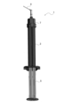
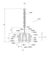
- FIG. 2 is a perspective view of a paste injector equipped with a static mixer according to the first embodiment.
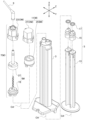
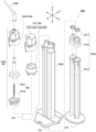
- FIG. 2 is an exploded perspective view of the paste injector of the first embodiment.
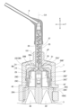
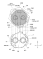
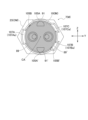
- 1 is a cross-sectional view of a static mixer fixed to the tip of a syringe in Example 1, cut in the width direction at a position passing through a central axis extending in the longitudinal direction.
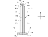
- FIG. FIG. 2 is a front view of the syringe of the first embodiment.
- FIG. 2 is a side view of the syringe of Example 1.
- FIG. 2 is a plan view of the syringe of the first embodiment.
- FIG. 2 is a bottom view of the syringe of Example 1.
- FIG. 2 is a front view of the plunger body of the first embodiment.
- FIG. 4 is a side view of the plunger body of the first embodiment.
- FIG. 2 is a plan view of the plunger body of the first embodiment.
- FIG. 4 is a bottom view of the plunger body of the first embodiment. 7A, taken along the line VIII-VIII.
- FIG. 2 is a perspective view of an elastic body holder according to the first embodiment.
- FIG. 4 is a bottom view of the elastic body holder of the first embodiment.
- FIG. 1 is a cross-sectional view of an elastic holder in a paste injector according to a first embodiment, with an O-ring attached to an annular groove, cut in a width direction perpendicular to the longitudinal direction at a neck portion.
- FIG. FIG. 1 is a cross-sectional view (schematic diagram) of the paste injector of Example 1, in which an elastic holder with an O-ring attached to an annular groove is inserted into a paste storage chamber of a syringe and cut in a width direction perpendicular to the longitudinal direction at the neck portion, and a cross-sectional view (schematic diagram) as viewed from the front and side.
- FIG. 2 is a perspective view of a mixing tip body of the first embodiment.
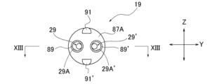
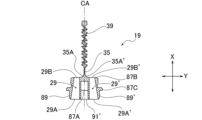
- FIG. 2 is a bottom view of the mixing tip body of the first embodiment. 13 is a cross-sectional view taken along line XIII-XIII shown in FIG. 12B.
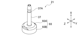
- FIG. 2 is a perspective view of a mixer housing according to the first embodiment.
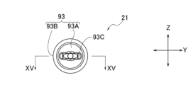
- FIG. 2 is a bottom view of the mixer housing of the first embodiment. This is a cross-sectional view of line XV-XV shown in Figure 14B.
- FIG. 2 is a front view of the mixer exterior body of the first embodiment.
- FIG. 2 is a plan view of the mixer exterior body of the first embodiment.
- FIG. 2 is a bottom view of the mixer exterior body of the first embodiment. This is a cross-sectional view taken along line XVII-XVII shown in Figure 16B.
- FIG. 16B is a cross-sectional view taken along line XVIII-XVIII shown in FIG. 16A.
- FIG. 2 is a perspective view of a cap inner member of the first embodiment.
- FIG. 4 is a bottom view of the cap inner member of the first embodiment. This is a cross-sectional view taken along line XX-XX shown in Figure 19B.
- FIG. 2 is a front view of the cap exterior body of the first embodiment.
- FIG. 2 is a plan view of a cap exterior body according to the first embodiment.
- FIG. 2 is a bottom view of the cap exterior body of the first embodiment. This is a cross-sectional view taken along line XXII-XXII shown in Figure 21B.
- FIG. 1 is a diagram showing a state prior to the stage in which a static mixer is placed over and fixed to a syringe in the paste injector of Example 1.
- FIG. 2 is a bottom view of the static mixer after only the mixer exterior body has rotated in the paste injector of Example 1.
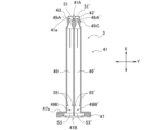
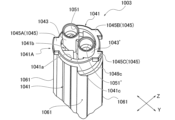
- FIG. 11 is an exploded perspective view of a paste injector according to a second embodiment. 1 is a cross-sectional view of a static mixer fixed to the tip of a syringe of Example 2, cut in the width direction at a position passing through the central axis extending in the longitudinal direction.
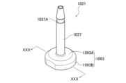
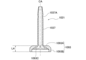
- FIG. 11 is a perspective view of the tip portion of the syringe of Example 2.
- FIG. 11 is a plan view of a syringe according to a second embodiment. This is a main part of the cross-sectional view taken along line XXVIII-XXVIII shown in Figure 28B.
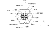
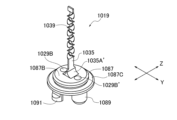
- FIG. 11 is a perspective view of a mixing tip body of the second embodiment.
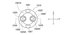
- FIG. 11 is a bottom view of the mixing tip body of the second embodiment. This is a cross-sectional view taken along line XXIX-XXIX shown in Figure 29B.
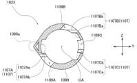
- FIG. 11 is a perspective view of a mixer housing according to a second embodiment. This is a cross-sectional view taken along line XXX-XXX shown in Figure 30A.
- FIG. 11 is a perspective view of the tip portion of the syringe of Example 2.
- FIG. 11 is a plan view of a syringe according to a second embodiment. This is a main part of the cross
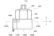
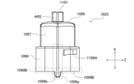
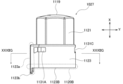
- FIG. 11 is a front view of the mixer exterior body of the second embodiment.
- FIG. 11 is a side view of a mixer exterior body of the second embodiment.
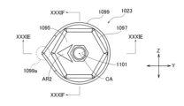
- FIG. 11 is a plan view of a mixer exterior body of a second embodiment.
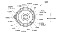
- FIG. 11 is a bottom view of the mixer exterior body of the second embodiment.
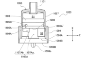
- This is a cross-sectional view taken along line XXXIE-XXXIE shown in Figure 31C.
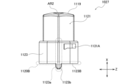
- FIG. 11 is a front view of a cap exterior body according to a second embodiment.
- FIG. 11 is a front view of a cap exterior body according to a second embodiment.
- FIG. 11 is a side view of a cap exterior body according to a second embodiment.
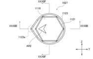
- FIG. 11 is a plan view of a cap exterior body according to a second embodiment.
- FIG. 11 is a bottom view of the mixer exterior body of the second embodiment.
- This is a cross-sectional view taken along line XXXIIE-XXXIIE shown in Figure 32C.
- This is a cross-sectional view of line XXXIIF-XXXIIF shown in Figure 32C.
- Fig. 1 is a perspective view of a paste injector 1 equipped with a static mixer 7 according to a first embodiment
- Fig. 2 is an exploded perspective view of the paste injector 1 according to the first embodiment.
- a longitudinal direction (X), a width direction (Y), and a thickness direction (Z) are defined for the paste injector 1.
- the paste injector 1 comprises a syringe 3, a plunger 5, a static mixer 7, and a guide tip 9.
- the paste injector 1 of the first embodiment two types of paste individually filled in the syringe 3 are pushed out by the plunger 5, mixed just before use by the static mixer 7 to prepare a dental material, and then injected into the desired location (such as an affected area or a dental cap) via the guide tip 9.
- the guide tip 9 is a nozzle member that is attached to the static mixer 7 in a fixed fit state as necessary. The paste injector 1 can be used even if the guide tip 9 is not attached to the static mixer 7.
- a cap 11 shown in FIG. 2 is fixed to the tip of the syringe 3 (one end 41A of the syringe body 41 described below) instead of the static mixer 7.
- the static mixer 7 and cap 11 detachably attached to the tip of the syringe 3 are collectively referred to as the attachment member M.
- the syringe 3, plunger 5, and attachment member M extend in the longitudinal direction X shown in FIG. 2 and are assembled with the central axis CA that passes through the center of each component aligned.
- the syringe 3 is filled with paste in advance and distributed with the plunger 5 inserted.
- the plunger 5 is composed of a plunger body 13, an elastic body holder 15 that loosely engages with the tip of the plunger body 13, and an annular O-ring (elastic body) 17 attached to the elastic body holder 15.
- "Loosely engaged” here means that the elastic body holder 15 is engaged with the plunger body 13 with such an engagement force that the friction between the syringe 3 and the O-ring 17 causes the elastic body holder 15 to come off from the plunger body 13.
- the elastic body holder 15 and the O-ring 17 form the tip of the plunger 5.
- the plunger 5 may be an integrated unit that is not separated into the plunger body 13 and the elastic body holder 15. In this case, the annular O-ring 17 may be attached directly to the tip of the plunger 5.
- the static mixer 7 is composed of a mixing tip main body 19, a mixer housing 21, and a mixer exterior body 23.
- the cap 11 is composed of a cap inner member 25 and a cap outer body 27.
- FIG. 3 is a cross-sectional view of the static mixer 7 fixed to the tip of the syringe 3, taken in the width direction Y at a position passing through a central axis CA extending in the longitudinal direction X.
- the paste flow path is composed of paste passages 29 and 29', an intermediate passage 31, and a mixing passage 33.
- the paste passages 29, 29' are arranged circumferentially about the central axis CA, are symmetrically arranged along the width direction Y, and each extends in the longitudinal direction X.
- the mixing passage 33 is located downstream of the paste passages 29, 29' in the paste flow direction, and extends around the central axis CA extending in the longitudinal direction X.
- the intermediate passage 31 is a passage that connects the paste passages 29, 29' and the mixing passage 33.
- the paste passage 29 is a passage through which the paste discharged from the paste storage chamber 49 of the syringe 3 flows.
- the paste passage 29 has an inlet hole 29A through which the paste flows and an outlet hole 29B through which the paste flows out, and is formed in the mixing tip main body 19.
- the opening area of the inlet hole 29A is larger than the opening area of the outlet hole 29B.
- the opening center point of the outlet hole 29B is set at a position closer to the central axis CA than the opening center point of the inlet hole 29A.
- the inner circumferential surface of the paste passage 29 has a tapered portion on the distal surface 29C away from the central axis CA when viewed in a cross section perpendicular to the thickness direction Z.
- the tapered portion of the distal surface 29C of the first embodiment is formed in a tapered shape that gradually approaches the central axis CA as it moves from the inlet hole 29A to the outlet hole 29B. In other words, the tapered portion of the first embodiment extends at a constant angle from the inlet hole 29A to the outlet hole 29B.
- the inner circumferential surface of the paste passage 29 has a proximal surface 29D close to the central axis CA when viewed in a cross section perpendicular to the thickness direction Z, which extends parallel to the central axis CA from the inlet hole 29A to the outlet hole 29B, and is aligned with the central axis CA. Therefore, the area of the cross section perpendicular to the central axis CA (longitudinal direction X) of the paste passage 29 of the first embodiment gradually decreases at a constant rate from the inlet hole 29A to the outlet hole 29B.
- the paste passage 29' is a passage through which the paste discharged from the paste storage chamber 49' of the syringe 3 flows. Since the paste passage 29' has the same configuration as the paste passage 29, the reference numerals of the various parts of the paste passage 29 are followed by "", and the explanation is omitted.
- the paste passage 29 and the paste passage 29' are formed to have the same size and are symmetrical in the width direction Y with respect to the central axis CA. That is, the inlet hole 29A and the inlet hole 29A' are set to have the same opening area, and the outlet hole 29B and the outlet hole 29B' are set to have the same opening area. Furthermore, when viewed along the central axis CA, the distance from the central axis CA to the center of the inlet hole 29A is the same as the distance from the central axis CA to the inlet hole 29A'. Furthermore, when viewed along the central axis CA, the distance from the central axis CA to the center of the outlet hole 29B is the same as the distance from the central axis CA to the outlet hole 29B'. Furthermore, the inclination angle of the distal surface 29C relative to the central axis CA is the same as the inclination angle of the distal surface 29C' relative to the central axis CA.
- the intermediate passage 31 is a passage that guides the paste flowing out from the outlet holes 29B, 29B' to the joining position JP.
- a backflow prevention wall 35 is provided between the outlet holes 29B and 29B'.
- the backflow prevention wall 35 divides the intermediate passage 31 into the outlet hole 29B side and the outlet hole 29B' side, and prevents the paste that flows out from one outlet hole 29B (29B') from flowing into the other outlet hole 29B' (29B).
- the backflow prevention wall 35 stands up from the end face of the mixing tip main body 19 where the outlet holes 29B, 29B' are formed, and extends to the joining position JP along the central axis CA.
- the backflow prevention wall 35 has curved surfaces 35A, 35A' at the base that direct the paste toward the joining position JP.
- the mixing passage 33 is a passage through which the pastes that join at the joining position JP pass while being mixed, and extends around a central axis CA that extends in the longitudinal direction X.
- the mixing passage 33 is composed of an element housing portion 37 that extends cylindrically in the mixer housing 21, and an element group 39 that extends from the end of the backflow prevention wall 35 and is inserted into the element housing portion 37.
- the static mixer 7 or the cap 11, which is the mounting member M, is detachably mounted to the tip end portion (one end portion 41A of the syringe body 41) of the syringe 3.
- the fixing structure will be described below.
- the mounting member M is composed of an inner member IM and an outer body OM.
- the mounting member M is a static mixer 7
- the mixing tip main body 19 and the mixer housing 21 form the inner member IM
- the mixer outer body 23 forms the outer body OM.
- the mounting member M is a cap 11
- the cap inner member 25 forms the inner member IM
- the cap outer body 27 forms the outer body OM.
- the mixing tip main body 19 and the mixer housing 21 are arranged inside the mixer exterior body 23 (exterior body OM).
- the mixing tip main body 19 and the mixer housing 21 are configured to be rotatable around the central axis CA relative to the mixer exterior body 23 within a predetermined angle range.
- the cap inner member 25 is arranged inside the cap exterior body 27 (exterior body OM).
- the cap inner member 25 is configured to be rotatable around the central axis CA relative to the cap exterior body 27 within a predetermined angle range.
- the tip of the syringe 3 (one end 41A of the syringe body 41) is inserted into the exterior body OM via the inner member IM along the central axis CA
- the inner member IM cannot rotate relative to the syringe 3
- the exterior body OM can rotate relative to the syringe 3.
- the exterior body OM rotates around the central axis CA, so that only the exterior body OM rotates relative to the syringe 3, and the mounting member M is fixed to the tip of the syringe 3 (one end 41A of the syringe body 41) via an engagement structure.
- the engagement structure has three or more pairs (three pairs in the first embodiment) of engagement pairs each consisting of an engagement portion 45 formed on the syringe 3 and an engaged portion 107 formed on the mixer exterior body 23, which is the exterior body OM, or an engagement portion 45 formed on the syringe 3 and an engaged portion 129 formed on the cap exterior body 27, which is the exterior body OM.
- the detailed configurations of the engagement portion 45, the engaged portion 107, and the engaged portion 129 will be described later.
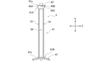
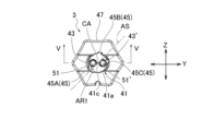
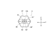
- Fig. 4A is a front view of the syringe 3
- Fig. 4B is a side view
- Fig. 4C is a plan view
- Fig. 4D is a bottom view.
- Fig. 5 is a cross-sectional view taken along line VV shown in Fig. 4C
- Fig. 6 is an end view taken along line VI-VI shown in Fig. 4A.
- the syringe 3 is a cylindrical body extending in the longitudinal direction X, and includes a syringe body 41, two protrusions 43, 43', an engagement portion 45, and a finger hook portion 47.
- the syringe body 41 has multiple (two in this example) paste storage chambers 49 and paste storage chambers 49' formed inside, which are filled with paste.
- the two paste storage chambers 49, 49' are lined up inside the syringe body 41 along the width direction Y, and are formed to have the same shape.
- One end 41A of the syringe body 41 is formed with a circular wall portion 41a that has a circular shape when cut in the width direction Y perpendicular to the longitudinal direction X, and the other end 41B is formed with a finger hook portion 47.
- the two protrusions 43, 43' are cylindrical parts that protrude in the longitudinal direction X from the end face of one end 41A (circular wall part 41a) of the syringe body 41, and their tips serve as outlets 51, 51'.
- the inner periphery of the protrusion 43 forms part of the paste storage chamber 49, and the inner periphery of the protrusion 43' forms part of the paste storage chamber 49'.
- the two protrusions 43, 43' are connected via an upright wall 41c that stands up from the circular wall part 41a, and the inclination is regulated.
- the engaging portion 45 constitutes an engaging structure that fixes the mounting member M to the tip of the syringe 3 (one end 41A of the syringe body 41), and is a portion that engages with the engaged portion (engaged portion 107 and engaged portion 129) of the mounting member M (static mixer 7 and cap 11).
- the engaging portion 45 is composed of three protruding pieces 45A, 45B, and 45C formed on the outer circumferential surface of the circular wall portion 41a of the syringe body 41, as shown in FIG. 4C.
- the protrusions 45A, 45B, and 45C are aligned in the direction of rotation of the outer casing OM, and when viewed along the central axis CA, are asymmetrical about the central axis CA, which is the center of rotation of the outer casing OM.
- point symmetry generally means that a figure will overlap with the original figure when rotated 180° about the point of symmetry, but “asymmetrical” here means that the protrusions 45A, 45B, and 45C do not overlap when the syringe 3 rotates about the central axis CA, except when rotated 360°.
- the protrusions 45A, 45B, and 45C are arranged at unequal intervals along the rotational direction of the outer casing OM.
- the distance in the rotational direction from protrusion 45A to protrusion 45B is the same as the distance in the rotational direction from protrusion 45A to protrusion 45C.
- the distance in the rotational direction from protrusion 45B to protrusion 45C is shorter than the distance from protrusion 45A to protrusion 45B and the distance from protrusion 45A to protrusion 45C.
- protrusions 45A, 45B, and 45C each have a different shape when viewed along the central axis CA. That is, the length of protrusion 45A in the rotational direction is longer than the lengths of protrusions 45B and 45C in the rotational direction. On the other hand, protrusions 45B and 45C have the same length in the rotational direction, but protrude in different directions from the outer circumferential surface of circular wall portion 41a.
- protrusions 45B and 45C are symmetrical with respect to a symmetry axis AS that passes through the central axis CA and the circumferential center position of protrusion 45A.
- An arrow AR1 indicating the position of protrusion 45A is engraved on the surface of circular wall portion 41a.
- the finger hook portion 47 is a flange-shaped portion that extends in the width direction Y and thickness direction Z from the outer peripheral surface of the other end 41B of the syringe body 41. As shown in Figures 4C and 4D, the finger hook portion 47 of Example 1 has an outer peripheral shape that is approximately hexagonal. Note that the surface 47a of the finger hook portion 47 on at least one of the end portions 41A may be textured. By embossing the surface 47a, it is possible to prevent fingers from slipping during use and to make gate marks less noticeable, thereby improving the quality of the appearance.
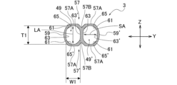
- the outer periphery of the syringe body 41 has a pair of widthwise outer periphery surfaces 57, 57', a pair of thicknesswise outer periphery surfaces 59, 59', and four connecting outer periphery surfaces 61.
- the pair of widthwise outer peripheral surfaces 57, 57' are surfaces of the outer peripheral surface of the syringe body 41 that are located on opposite sides along the thickness direction Z.
- the widthwise outer peripheral surfaces 57, 57' each have a flat portion 57A that is flat along the longitudinal direction X and the width direction Y.
- the widthwise outer peripheral surfaces 57, 57' each have a groove-shaped recessed portion 57B that extends in the longitudinal direction X and is recessed more than the flat portion 57A.
- the recessed portion 57B is located between the two paste storage chambers 49, 49' formed inside the syringe body 41, and the flat portion 57A is divided into two by the recessed portion 57B along the width direction Y.
- the recessed portion 57B has a wedge-shaped cross section whose length in the width direction Y gradually narrows as it becomes deeper.
- the pair of thickness-direction outer peripheral surfaces 59, 59' are surfaces of the outer peripheral surface of the syringe body 41 that are located on opposite sides along the width direction Y.
- the thickness-direction outer peripheral surfaces 59, 59' are curved outward in the width direction Y with a predetermined radius of curvature, and in this case are set to a curved surface of R5.
- the connecting outer peripheral surface 61 is a surface that is set between the width direction outer peripheral surface 57 and the thickness direction outer peripheral surface 59, between the width direction outer peripheral surface 57' and the thickness direction outer peripheral surface 59, between the width direction outer peripheral surface 57 and the thickness direction outer peripheral surface 59', and between the width direction outer peripheral surface 57' and the thickness direction outer peripheral surface 59', among the outer peripheral surfaces of the syringe body 41.
- the connecting outer peripheral surface 61 is curved with a predetermined radius of curvature (for example, radius of curvature R1 to R5, R1.5 in Example 1), and smoothly connects the width direction outer peripheral surface 57 and the thickness direction outer peripheral surface 59, the width direction outer peripheral surface 57' and the thickness direction outer peripheral surface 59, the width direction outer peripheral surface 57 and the thickness direction outer peripheral surface 59', and the width direction outer peripheral surface 57' and the thickness direction outer peripheral surface 59', respectively.
- the connecting outer peripheral surface 61 and the pair of thickness direction outer peripheral surfaces 59, 59' are formed by combining multiple curved surfaces set to different radii of curvature.
- the connecting outer periphery 61 and the pair of thickness direction outer periphery surfaces 59, 59' may be formed by curved surfaces set to the same radius of curvature.
- the paste storage chamber 49 has a discharge port 51 at one end 49A (projection 43) that opens one end of the paste storage chamber 49 and discharges the paste pushed out by the plunger 5, and a filling port 53 at the other end 49B that opens the other end of the paste storage chamber 49.
- the paste storage chamber 49 has a tapered shape at one end 49A into which the tip of the plunger 5 (top 83 of the elastic holder 15) inserted into the paste storage chamber 49 fits.
- a stopper protrusion 55 is provided on the inner surface of the other end 49B to prevent the plunger 5 inserted into the paste storage chamber 49 from falling out. Since the paste storage chamber 49' has the same configuration as the paste storage chamber 49, the same reference numerals as the various parts of the paste storage chamber 49 are used and a description thereof is omitted.
- the cross section of the paste storage chamber 49 taken in a direction perpendicular to the longitudinal direction X has an elliptical shape with the long axis direction LA aligned with the thickness direction Z and the short axis direction SA aligned with the width direction Y.
- elliptical shape refers to an elliptical shape defined by geometry, as well as shapes that approximate an ellipse, such as an oval (a shape formed by connecting two semicircles with two straight lines), an elliptical arch shape (a shape formed by cutting out a part of an ellipse along a straight line), a flattened ellipse (a shape formed by crushing an ellipse in the long axis or short axis direction), and an oval shape.
- the inner peripheral surface of the paste storage chamber 49 is composed of a pair of inner flat surface portions 63, 63' that are flat along the longitudinal direction X and the thickness direction Z, and a pair of inner curved surface portions 65, 65' that are curved at a predetermined curvature.
- the pair of inner flat surface portions 63, 63' face each other in the width direction Y, sandwiching the internal space of the paste storage chamber 49.
- the pair of inner curved surface portions 65, 65' face each other in the thickness direction Z, sandwiching the internal space of the paste storage chamber 49, and smoothly connect the pair of inner flat surface portions 63, 63'.
- the cross-sectional shape of the inner surface of the paste storage chamber 49 is an oblate ellipse.
- the length dimension T1 in the long axis direction LA of the elliptical shape of the inner peripheral surface of the paste storage chamber 49 is preferably within the range of 1.1 to 2.0, where the length dimension W1 in the short axis direction SA is 1.
- the length dimension T1 in the long axis direction LA is set to 1.3, where the length dimension W1 in the short axis direction SA is 1.
- the length dimension T1 in the long axis direction LA is preferably 5 mm to 20 mm
- the length dimension W1 in the short axis direction SA is preferably 4.5 mm to 10 mm.
- Fig. 7A is a front view of the plunger body 13
- Fig. 7B is a side view
- Fig. 7C is a plan view
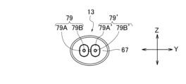
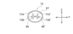
- Fig. 7D is a bottom view
- Fig. 8 is a cross-sectional view taken along line VIII-VIII shown in Fig. 7A.
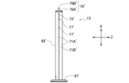
- the plunger body 13 has a pressing portion 67 and two rod-shaped portions 69 and 69'.
- the pressing portion 67 is a portion that is pressed with a finger (e.g., thumb) when the user holds the syringe 3 between two fingers (e.g., the index finger and middle finger) and places the fingers on the finger hook portion 47 to push the plunger 5 into the syringe 3.
- the pressing portion 67 has an outer periphery that is elliptical and long in the width direction Y, and has two rod-shaped portions 69, 69' disposed in the center.
- the bottom surface of the pressing portion 67 is curved in the direction in which the rod-shaped portions 69, 69' extend so that the user can easily press it with their fingers.
- the rod-shaped portions 69, 69' are rod-shaped portions extending in parallel from the pressing portion 67 along the longitudinal direction X.
- the rod-shaped portions 69, 69' are arranged at a predetermined interval along the longitudinal direction (width direction Y) of the pressing portion 67, and are inserted simultaneously into the paste storage chambers 49, 49', respectively.
- the rod-shaped portions 69 and 69' have the same shape, and both can be inserted into both the paste storage chambers 49, 49'.
- the rod-shaped portion 69 has a cross-shaped cross section in the width direction Y, which is made up of a combination of a thickness direction wall portion 71A extending in the thickness direction Z and a width direction wall portion 71B extending in the width direction Y.
- the length dimension in the thickness direction Z of the thickness direction wall portion 71A is greater than the length dimension in the width direction Y of the width direction wall portion 71B.
- the tip of the thickness direction wall portion 71A is aligned along the inner curved surface portions 65, 65' of the paste storage chamber 49 (49'), and the tip of the width direction wall portion 71B is aligned along the inner flat surface portions 63, 63' of the paste storage chamber 49 (49').
- a pair of protrusions 73, 73 formed to protrude in the width direction Y and a pair of cutouts 75, 75 are formed on one end of the width direction wall 71B in the longitudinal direction X.
- the pair of protrusions 73, 73 of the width direction wall 71B come into contact with the inner flat surface portions 63, 63', and the portion of the width direction wall 71B where the pair of cutouts 75, 75 are formed is deflected.
- the rod-shaped portion 69 is positioned in the width direction Y, and rattling is prevented.
- a plurality of protrusions 77 are formed on the thickness direction wall 71A and the width direction wall 71B in order to prevent rattling of the rod-shaped portion 69.
- the rod-shaped portion 69 has a holder engagement portion 79 formed at its tip with which the elastic holder 15 is loosely engaged.
- the holder engagement portion 79 has a tip wall portion 79A that contacts the bottom surface 81A of the elastic holder 15, and an engagement protrusion 79B that extends from the tip wall portion 79A in the longitudinal direction X and is inserted into an engaged hole 81B formed in the bottom surface 81A of the elastic holder 15.
- the tip wall portion 79A has an outer peripheral shape that is an ellipse that follows the cross-sectional shape of the paste storage chamber 49 (49').
- rod-shaped portion 69' has the same configuration as rod-shaped portion 69, the reference numerals of the various parts of rod-shaped portion 69 are followed by "", and the explanation is omitted.
- FIG. 9A is a perspective view of the elastic body holder 15, and FIG. 9B is a bottom view.
- the elastic holder 15 is loosely engaged with the holder engagement portions 79, 79' at the tip of the plunger body 13, one by one, to form the tip of the plunger 5.
- the elastic holder 15 has a body 81, a top 83, and a neck 85.
- the body 81 is a portion whose cross section in the width direction Y is elliptical.
- the bottom surface 81A of the body 81 is formed with an engaged hole 81B into which the engagement protrusion 79B of the holder engagement portion 79 or the engagement protrusion 79B' of the holder engagement portion 79' is inserted.
- the outer peripheral surface 81C of the body 81 has an elliptical shape that follows the elliptical shape of the inner peripheral surface (inner flat surface portions 63, 63' and inner curved surface portions 65, 65') of the paste storage chamber 49 (49').
- the top 83 has a shape that becomes thinner toward the tip.
- the neck 85 is an elliptical portion formed between the body 81 and the top 83.
- the neck portion 85 and the body portion 81 and top portion 83 that face each other across the neck portion 85 form an annular groove portion 81D in which the O-ring 17 is attached.
- the elliptical shape of the body 81 is smaller than the cross-sectional shape of the paste storage chamber 49 (49'), and is similar to the cross-sectional shape of the paste storage chamber 49 (49'), and follows the elliptical shape of the inner peripheral surface of the paste storage chamber 49 (49'). Therefore, when the elastic holder 15 is inserted into the paste storage chamber 49 (49'), the distance from the outer peripheral surface 81C of the body 81 to the inner peripheral surface of the paste storage chamber 49 (49') is constant over the entire circumference of the body 81.
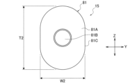
- the length dimension T2 in the major axis direction of the elliptical shape of the body 81 is preferably within the range of 1.1 to 2.0, assuming that the length dimension W2 in the minor axis direction is 1.
- the length dimension T2 in the major axis direction is set to 1.3, assuming that the length dimension W2 in the minor axis direction is 1.
- the elliptical shape of the neck portion 85 is smaller than that of the body portion 81, and has a cross-sectional shape similar to that of the body portion 81.
- the elliptical shape of the neck portion 85 has a cross-sectional shape similar to that of the paste storage chamber 49 (49'). Therefore, when the elastic holder 15 is inserted into the paste storage chamber 49 (49'), the distance from the outer peripheral surface 85C of the neck portion 85 to the inner peripheral surface of the paste storage chamber 49 (49') is constant around the entire circumference of the neck portion 85.
- the ratio of the length dimension in the major axis direction to the length dimension in the minor axis direction of the elliptical shape of the neck portion 85 is set to the same ratio as that of the elliptical shape of the body portion 81.
- FIG. 10 is a cross-sectional view of the elastic holder 15 with the O-ring 17 attached to the annular groove 81D, cut in the width direction Y perpendicular to the longitudinal direction X at the neck portion 85.
- the O-ring 17 is annular, but the neck portion 85 has an elliptical shape. Therefore, when the O-ring 17 is attached to the annular groove 81D, it is stretched in the major axis direction (thickness direction Z) and becomes elliptical.
- the length dimension T3 of the elliptical O-ring 17 in the major axis direction is larger than the length dimension T2 of the elliptical shape of the body portion 81 in the major axis direction.
- the length dimension W3 of the elliptical O-ring 17 in the minor axis direction is larger than the length dimension W2 of the elliptical shape of the body portion 81 in the minor axis direction. Therefore, the O-ring 17 is fixed in a state where it protrudes from the annular groove 81D.
- the wire diameter ⁇ A of the O-ring 17 in region a is thinner than the wire diameter ⁇ B in region b, and the wire diameter of the O-ring 17 varies depending on the circumferential position.
- the "wire diameter of the O-ring 17" refers to the cross-sectional thickness of the O-ring 17.
- the amount of protrusion of the O-ring 17 from the annular groove portion 81D varies, and the thinner the wire diameter (e.g., region a), the less the protrusion from the annular groove portion 81D.
- the length dimension T3 in the major axis direction of the elliptical O-ring 17 is slightly larger than the length dimension T1 in the major axis direction of the elliptical shape of the inner peripheral surface of the paste storage chamber 49 or the paste storage chamber 49'.
- the length dimension W3 in the minor axis direction of the elliptical O-ring 17 is slightly larger than the length dimension W1 in the minor axis direction of the elliptical shape of the inner peripheral surface of the paste storage chamber 49 or the paste storage chamber 49'.
- the O-ring 17 comes into contact with the inner peripheral surface of the paste storage chamber 49 (49') and is compressed by being sandwiched between the inner peripheral surface of the paste storage chamber 49 (49') and the outer peripheral surface 85C of the neck portion 85.
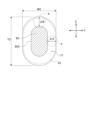
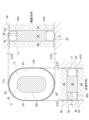
- FIG. 11 shows a cross-sectional view (schematic diagram) of the elastic holder 15 with the O-ring 17 attached to the annular groove 81D inserted into the paste storage chamber 49 of the syringe 3, cut at the neck portion 85 in the width direction Y perpendicular to the longitudinal direction X, and cross-sectional views (schematic diagrams) as viewed from the front and side.
- FIG. 11 the part of the O-ring 17 that protrudes from the annular groove 81D and is compressed when inserted into the paste storage chamber 49 is shown colored gray, and the state of the O-ring 17 before compression is shown by a dashed line.
- the O-ring 17 is compressed by being sandwiched between the inner circumferential surface of the paste storage chamber 49 (the inner flat surface portions 63, 63' and the inner curved surface portions 65, 65') and the outer circumferential surface 85C of the neck portion 85.
- the wire diameter of the O-ring 17 varies depending on the circumferential position, and the thinner the wire diameter, the less it protrudes from the annular groove 81D.
- the difference ( ⁇ X1, ⁇ X2) between the distance Gd from the outer peripheral surface 85C of the neck portion 85 to the inner peripheral surface of the paste storage chamber 49 and the wire diameter Wr of the O-ring 17 varies depending on the circumferential position of the O-ring 17. Therefore, the compression rate of the O-ring 17 when inserted into the paste storage chamber 49 differs depending on the circumferential position.
- the elliptical O-ring 17 protrudes more from the annular groove portion 81D in region b, which has a thicker wire diameter, than in region a, which has a thinner wire diameter, and the difference ⁇ X2 in region b is greater than the difference ⁇ X1 in region a. Therefore, when inserted into the syringe 3, region b of the O-ring 17 is pressed more toward the inside of the paste storage chamber 49 than region a, and the compression rate in region b is greater than the compression rate in region a. As a result, the compression rate in the major axis direction (thickness direction Z) of the elliptical O-ring 17 is greater than the compression rate in the minor axis direction (width direction Y) of the O-ring 17.
- the compression rate of the O-ring 17 varies depending on the circumferential position, and therefore the frictional force between the O-ring 17 and the inner peripheral surface of the paste storage chamber 49 (49') varies depending on the circumferential position of the O-ring 17. That is, the frictional force between the apex 17A in the long axis direction of the O-ring 17 stretched into an elliptically shape and the inner peripheral surface of the paste storage chamber 49 (49') is greater than the frictional force between the apex 17B in the short axis direction of the O-ring 17 stretched into an elliptically shape and the inner peripheral surface of the paste storage chamber 49 (49').
- the compression ratio of the O-ring 17 in the major axis direction is about 10 to 14%
- the compression ratio in the minor axis direction is about 3 to 7%.
- the compression ratio in the major axis direction is 12%
- the compression ratio in the minor axis direction is 5%.
- Gd Distance from the outer peripheral surface of the neck portion to the inner peripheral surface of the paste storage chamber [mm]
- the elastic body holder 15 is loosely engaged with the holder engagement portion 79 (79') at the tip of the plunger body 13. Therefore, when the elastic body holder 15, with the O-ring 17 attached, is inserted into the paste storage chamber 49 (49') of the syringe 3 together with the plunger body 13, the plunger body 13 is pushed in, and the elastic body holder 15 moves in the longitudinal direction X together with the plunger body 13 within the paste storage chamber 49 (49'). On the other hand, when the plunger body 13 is pulled back, it is separated from the plunger body 13 and left behind in the paste storage chamber 49 (49'). This prevents air from being drawn into the paste storage chamber 49 (49') from the outlet 51, (51') even if the plunger 5 is pulled back by mistake.
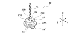
- Fig. 12A is a perspective view of the mixing tip body 19
- Fig. 12B is a bottom view
- Fig. 13 is a cross-sectional view taken along line XIII-XIII shown in Fig. 12B.
- the mixing tip body 19 is a member that, in combination with the mixer housing 21, constitutes the inner member IM of the static mixer 7, which is the mounting member M.
- the mixing tip body 19 includes a base 87, two insertion portions 89, 89', a pair of rotating engagement pieces 91, 91', a backflow prevention wall 35, and an element group 39.
- the base 87 is a cylindrical portion that fits inside the mixer exterior body 23, which is the exterior body OM.
- a flange portion 87C that extends radially outward is formed on the outer periphery of the base 87.
- the mixing tip main body 19 is fixed to the mixer exterior body 23 in a relatively rotatable state about the central axis CA by fitting the flange portion 87C into a groove (circumferential groove 103) formed on the inner surface of the mixer exterior body 23 described below.
- the two insertion portions 89, 89' and the pair of rotary engagement pieces 91, 91' are formed on a first end surface 87A of the base 87 facing the syringe 3, and extend from the first end surface 87A in the longitudinal direction X.
- the two insertion portions 89, 89' are inserted into the two protrusions 43, 43' of the syringe 3, respectively.
- a paste passage 29 is formed inside the insertion portion 89, and a paste passage 29' is formed inside the insertion portion 89'.
- the pair of rotary engagement pieces 91, 91' are parts that respectively engage with the engagement grooves (a pair of first engagement grooves 105A, 105A' or a pair of second engagement grooves 105B, 105B') of the mixer exterior body 23 described below.
- the backflow prevention wall 35 extends along the central axis CA from the center of the second end face 87B opposite the first end face 87A of the base 87.
- the tip of the backflow prevention wall 35 is the paste joining position JP, and the element group 39 extends from the tip of the backflow prevention wall 35.
- the element group 39 is composed of multiple elements (eight in Example 1) lined up along the central axis CA.
- the paste passage 29 is formed by continuously penetrating the insertion portion 89 and the base portion 87.
- the inlet hole 29A is formed in the end face of the insertion portion 89
- the outlet hole 29B is formed in the second end face 87B of the base portion 87.
- the paste passage 29' is formed by continuously penetrating the insertion portion 89' and the base portion 87.
- the inlet hole 29A' is formed in the end face of the insertion portion 89'
- the outlet hole 29B' is formed in the second end face 87B of the base portion 87.
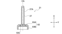
- Fig. 14A is a perspective view of the mixer housing 21
- Fig. 14B is a bottom view
- Fig. 15 is a cross-sectional view taken along line XV-XV shown in Fig. 14B.
- the mixer housing 21 is a member that, in combination with the mixing tip main body 19, constitutes the inner member IM of the static mixer 7, which is the mounting member M.
- the mixer housing 21 includes a base housing portion 93 and an element housing portion 37.
- the base housing portion 93 has a circular end wall portion 93A that covers the second end surface 87B of the base 87 of the mixing tip body portion 19 when the mixer housing 21 is placed over the mixing tip body portion 19, and a peripheral wall portion 93B that rises from the edge of the end wall portion 93A, surrounds the base portion 87, and extends until its tip contacts the flange portion 87C.
- the inner wall of the end wall portion 93A is provided with a recess 93C at a position opposite the outlet holes 29B, 29B'.
- the element housing portion 37 is a cylindrical portion that extends in the longitudinal direction X from a through hole formed in the center of the end wall portion 93A of the base housing portion 93 and has an open tip.
- the element housing portion 37 has an element group 39 inserted therein to form a mixing passage 33.
- a guide tip engagement groove 37A for fixing the guide tip 9 is formed on the outer periphery of the element housing portion 37.
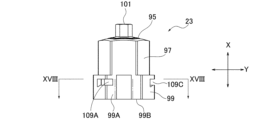
- Fig. 16A is a front view of the mixer exterior body 23
- Fig. 16B is a plan view
- Fig. 16C is a bottom view
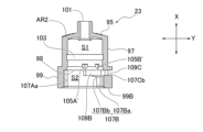
- Fig. 17 is a cross-sectional view taken along line XVII-XVII shown in Fig. 16B
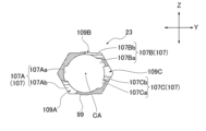
- Fig. 18 is a cross-sectional view taken along line XVIII-XVIII shown in Fig. 16A.
- the mixer exterior 23 is a cylindrical member that constitutes the exterior OM of the static mixer 7, which is the mounting member M.
- the static mixer 7, which is the mounting member M is constituted by storing the inner member IM consisting of the mixing tip main body 19 and the mixer housing 21 inside the mixer exterior 23.
- the mixer exterior 23 rotates relatively to the syringe 3 around the central axis CA.
- the mixer exterior 23 has a top wall 95 having a regular hexagonal outer peripheral shape, a first peripheral wall 97 rising from the edge of the top wall 95, and a second peripheral wall 99 extending continuously from the first peripheral wall 97 via a step.
- a first space S1 surrounded by the top wall 95 and the first peripheral wall 97, and a second space S2 surrounded by the second peripheral wall 99 are formed (see FIG. 17).
- An inner member IM consisting of a mixing tip main body 19 and a mixer housing 21 fits into the first space S1 in a state in which it can rotate around the central axis CA.
- the tip of the syringe 3 one end 41A of the syringe main body 41
- the inner member IM stored therein see FIG. 3).
- the top wall 95 covers the end wall 93A of the mixer housing 21 and faces the opening into which the syringe 3 is inserted (see FIG. 3).
- a top penetration tube 101 is formed in the center of the top wall 95 to expose the element housing 37 to the outside.
- the top penetration tube 101 is a cylindrical portion that protrudes from the top wall 95 and penetrates the top wall 95.
- the outer peripheral surface of the first peripheral wall portion 97 is a regular hexagon as shown in FIG. 16B.
- the inner peripheral surface of the first peripheral wall portion 97 is a circle as shown in FIG. 16C.
- the inner peripheral surface of the first peripheral wall portion 97 is formed with a circumferential groove 103, a pair of first engaged grooves 105A, 105A', and a pair of second engaged grooves 105B, 105B'.
- the circumferential groove 103 is a recess into which the flange portion 87C of the mixing tip body 19 fits, and extends in the circumferential direction (the direction of rotation of the inner member IM).
- the first engaged groove 105A and the second engaged groove 105B on one side are recesses with which one rotating engagement piece 91 engages.
- the first engaged groove 105A' and the second engaged groove 105B' on the other side are recesses with which the other rotating engagement piece 91' engages.
- the pair of first engaged grooves 105A, 105A' and the pair of second engaged grooves 105B, 105B' are arranged side by side in the circumferential direction (the direction of rotation of the inner member IM) with a predetermined gap between them.
- the pair of first engaged grooves 105A, 105A' are formed in positions that face each other in the thickness direction Z across the central axis CA.
- the pair of second engaged grooves 105B, 105B' are formed in positions that face each other in a direction that is shifted in the circumferential direction from the thickness direction Z across the central axis CA.
- the mixing tip body 19 and the mixer housing 21 rotate relative to the mixer exterior body 23 around the central axis CA.
- one rotating engagement piece 91 engages with either the first engaged groove 105A or the second engaged groove 105B on one side
- the other rotating engagement piece 91' engages with either the first engaged groove 105A' or the second engaged groove 105B' on the other side. This determines the relative rotational position of the mixing tip body 19 and the mixer housing 21 and the mixer exterior body 23.
- the second peripheral wall portion 99 When viewed along the central axis CA, the second peripheral wall portion 99 has an outer peripheral surface that is hexagonal as shown in FIG. 16B.
- the outer peripheral surface of the second peripheral wall portion 99 has a pair of long side portions 99A, 99A located on opposite sides of each other along the thickness direction Z.
- the pair of long side portions 99A, 99A bulge radially outward to allow the circular wall portion 41a of the syringe 3 to be inserted (see FIG. 16B, FIG. 16C, etc.).
- the inner peripheral surface of the second peripheral wall portion 99 When viewed along the central axis CA, the inner peripheral surface of the second peripheral wall portion 99 has a circular shape as shown in FIG. 16C.
- the inner circumferential surface of the second peripheral wall portion 99 is formed with a step portion 98 and an engaged portion 107 consisting of three indentations 107A, 107B, 107C.
- the step portion 98 is formed at the boundary between the first peripheral wall portion 97 and the second peripheral wall portion 99, and is a stepped unevenness that narrows the inner diameter of the mixer exterior body 23 toward the top wall portion 95, and extends in the circumferential direction (the direction of rotation of the inner member IM).
- the engaged portion 107 constitutes an engagement structure that fixes the mounting member M to the tip portion of the syringe 3 (one end portion 41A of the syringe body 41), and is the portion that engages with the engagement portion 45 (three protruding pieces 45A, 45B, 45C) of the syringe 3.
- the recesses 107A, 107B, 107C each have a first groove portion 107Aa, 107Ba, 107Ca and a second groove portion 107Ab, 107Bb, 107Cb.
- the first groove portions 107Aa, 107Ba, 107Ca open to the end face 99B of the second peripheral wall portion 99 (the opening of the mixer outer casing 23 into which the syringe 3 is inserted) and extend along the longitudinal direction X (central axis CA) to the step portion 98.
- the second groove portions 107Ab, 107Bb, 107Cb extend from the ends of the first groove portions 107Aa, 107Ba, 107Ca along the step portion 98 in the rotational direction of the mixer outer casing 23.
- windows 109A, 109B, and 109C are formed through the second peripheral wall 99.
- the second grooves 107Ab, 107Bb, and 107Cb are formed by the edges of the windows 109A, 109B, and 109C.
- the dents 107A, 107B, and 107C are aligned along the rotational direction of the mixer exterior body 23, and when viewed along the central axis CA, are asymmetrical about the central axis CA, which is the center of rotation of the mixer exterior body 23.
- the dents 107A, 107B, and 107C are aligned at unequal intervals along the rotational direction of the mixer exterior body 23. That is, the dent 107A is formed on the inner surface of the second peripheral wall portion 99 at a position corresponding to a corner portion of the outer peripheral surface of the second peripheral wall portion 99.
- the dents 107B and 107C are formed on the inner surface of the second peripheral wall portion 99 at positions corresponding to flat portions of the outer peripheral surface of the second peripheral wall portion 99 (see Figures 16C and 18).
- recess 107A has a shape into which protrusion 45A, which is the engagement portion 45, can be inserted
- recess 107B has a shape into which protrusion 45B, which is the engagement portion 45, can be inserted
- recess 107C has a shape into which protrusion 45C, which is the engagement portion 45, can be inserted.
- Recesses 107A, 107B, and 107C have different shapes when viewed along the central axis CA.
- cap 11 is fixed to the tip of the syringe 3 (one end 41A of the syringe body 41) in place of the static mixer 7 during storage or transportation of the paste injector 1.
- Components common to the static mixer 7 are given the same component names and descriptions thereof may be omitted.
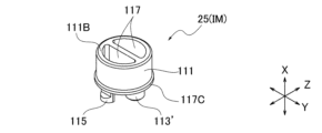
- Fig. 19A is a perspective view of the cap inner member 25
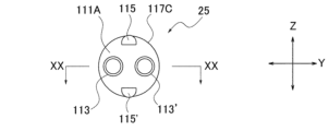
- Fig. 19B is a bottom view
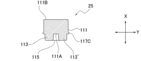
- Fig. 20 is a cross-sectional view taken along line XX-XX shown in Fig. 19B.
- the cap inner member 25 is a member that constitutes the inner member IM of the cap 11, which is the mounting member M, and corresponds to the mixing tip main body 19 and mixer housing 21, which are the inner members IM of the static mixer 7.
- the cap inner member 25 like the mixing tip main body 19, has a base 111, two insertion portions 113, 113', and a pair of rotating engagement pieces 115, 115'.
- the base 111 is a cylindrical portion that fits inside the cap outer body 27, which is the outer body OM.
- a flange portion 117C that extends radially outward is formed on the outer periphery of the base 111.
- the cap inner member 25 is fixed to the cap outer body 27 in a relatively rotatable state about the central axis CA by fitting the flange portion 117C into a groove (circumferential groove 125) formed on the inner periphery of the cap outer body 27 described below.
- the two insertion portions 113, 113' and the pair of rotating engagement pieces 115, 115' are formed on the first end face 111A of the base 111 facing the syringe 3, and extend from the first end face 111A in the longitudinal direction X.
- the two insertion portions 113, 113' are inserted into the two protrusions 43, 43' of the syringe 3, respectively.
- the insertion portions 113, 113' have a columnar shape for sealing the outlets 51, 51' of the syringe 3, and no passage is formed inside.
- the pair of rotating engagement pieces 115, 115' are parts that respectively engage with the engagement grooves (the pair of first engagement grooves 127A, 127A' or the pair of second engagement grooves 127B, 127B') of the cap exterior body 27 described below.
- a pair of bottomed recesses 117, 117 are formed on the second end face 111B opposite the first end face 111A of the base 111.
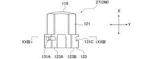
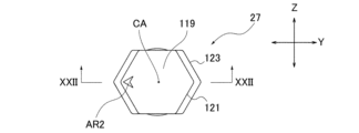
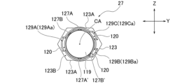
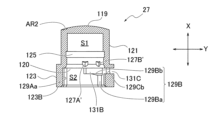
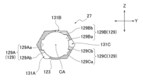
- Fig. 21A is a front view of cap exterior body 27
- Fig. 21B is a plan view
- Fig. 21C is a bottom view.
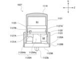
- Fig. 22 is a cross-sectional view taken along line XXII-XXII shown in Fig. 21B
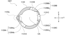
- Fig. 23 is a cross-sectional view taken along line XXIII-XXIII shown in Fig. 21A.
- the cap exterior body 27 is a cylindrical member that constitutes the exterior body OM of the cap 11, which is the mounting member M, and corresponds to the mixer exterior body 23, which is the exterior body OM of the static mixer 7.
- the cap inner member 25 is stored inside the cap exterior body 27, thereby forming the cap 11, which is the mounting member M.
- the cap exterior body 27 rotates relatively to the syringe 3 around the central axis CA.
- the cap exterior body 27 has a top wall portion 119 having a regular hexagonal outer peripheral shape, a first peripheral wall portion 121 rising from the edge of the top wall portion 119, and a second peripheral wall portion 123 extending continuously from the first peripheral wall portion 121 via a step.
- a first space S1 surrounded by the top wall portion 119 and the first peripheral wall portion 121, and a second space S2 surrounded by the second peripheral wall portion 123 are formed (see FIG. 22).
- An inner member IM consisting of the cap inner member 25 fits into the first space S1 in a state in which it can rotate around the central axis CA.
- the tip portion (one end 41A of the syringe body 41) a of the syringe 3 is inserted into the second space S2 with the inner member IM stored therein.
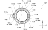
- Top wall portion 119 is the portion that closes off first space S1. Unlike the mixing tip main body portion 19, top wall portion 119 is made of a curved plate member, and does not have a top through tube formed in the center. Also, an arrow AR2 indicating the position of a recess 129A (described later) is engraved on the surface of top wall portion 119 (see FIG. 21B).
- the outer peripheral surface of the first peripheral wall portion 121 When viewed along the central axis CA, the outer peripheral surface of the first peripheral wall portion 121 has a regular hexagonal shape as shown in FIG. 21B. When viewed along the central axis CA, the inner peripheral surface of the first peripheral wall portion 121 has a circular shape as shown in FIG. 21C.
- the inner peripheral surface of the first peripheral wall portion 121 is formed with a circumferential groove 125, a pair of first engaged grooves 127A, 127A', and a pair of second engaged grooves 127B, 127B'.
- the circumferential groove 125 is a recess into which the flange portion 117C of the cap inner member 25 fits, and extends in the circumferential direction (the direction of rotation of the cap inner member 25).
- the first engaged groove 127A and the second engaged groove 127B on one side are recesses with which one rotating engagement piece 115 engages.
- the first engaged groove 127A' and the second engaged groove 127B' on the other side are recesses with which the other rotating engagement piece 115' engages.
- the pair of first engaged grooves 127A, 127A' and the pair of second engaged grooves 127B, 127B' are arranged side by side in the circumferential direction (the rotation direction of the cap inner member 25) with a predetermined gap between them.
- the pair of first engaged grooves 127A, 127A' are formed in positions that face each other in the thickness direction Z across the central axis CA.
- the pair of second engaged grooves 127B, 127B' are formed in positions that face each other in a direction that is shifted in the circumferential direction from the thickness direction Z across the central axis CA.
- the cap inner member 25 When assembled into the cap 11, the cap inner member 25 rotates relative to the cap exterior body 27 around the central axis CA. At this time, depending on the positional relationship in the rotational direction between the cap inner member 25 and the cap exterior body 27, one rotating engagement piece 115 engages with either the first engaged groove 127A or the second engaged groove 127B on one side, and the other rotating engagement piece 115' engages with either the first engaged groove 127A' or the second engaged groove 127B' on the other side. This determines the relative rotational position of the cap inner member 25 and the cap exterior body 27.
- the second peripheral wall portion 123 When viewed along the central axis CA, the second peripheral wall portion 123 has an outer peripheral surface that is hexagonal as shown in FIG. 21B.
- the outer peripheral surface of the second peripheral wall portion 123 has a pair of long sides 123A, 123A located on opposite sides of each other along the thickness direction Z.
- the pair of long sides 123A, 123A are shaped to bulge radially outward so that the circular wall portion 41a of the syringe 3 can be inserted (see FIG. 21B, FIG. 21C, etc.).
- the inner peripheral surface of the second peripheral wall portion 123 When viewed along the central axis CA, the inner peripheral surface of the second peripheral wall portion 123 has a circular shape as shown in FIG. 21C.
- the inner circumferential surface of the second peripheral wall portion 123 is formed with a step portion 120 and an engaged portion 129 consisting of three indentations 129A, 129B, 129C.
- the step portion 120 is formed at the boundary between the first peripheral wall portion 121 and the second peripheral wall portion 123, and is a stepped unevenness that narrows the inner diameter of the cap outer casing 27 toward the top wall portion 119, and extends in the circumferential direction (the direction of rotation of the inner member IM).
- the circular wall portion 41a of the syringe 3 abuts against the step portion 120 when the cap 11 is attached to the tip of the syringe 3.
- the engaged portion 129 constitutes an engagement structure that fixes the mounting member M to the tip of the syringe 3 (one end 41A of the syringe body 41), and is the portion that engages with the engagement portion 45 (three protruding pieces 45A, 45B, 45C) of the syringe 3.
- the recesses 129A, 129B, 129C have first groove portions 129Aa, 129Ba, 129Ca and second groove portions 129Ab, 129Bb, 129Cb, respectively.
- the first groove portions 129Aa, 129Ba, 129Ca open to the end face of the second peripheral wall portion 123 (the opening of the cap outer casing 27 into which the syringe 3 is inserted) and extend along the longitudinal direction X (central axis CA) to the step portion 120.
- the second groove portions 129Ab, 129Bb, 129Cb extend from the ends of the first groove portions 129Aa, 129Ba, 129Ca along the step portion 120 in the rotational direction of the cap outer casing 27.
- windows 131A, 131B, and 131C are formed through the second peripheral wall 123.
- the second grooves 129Ab, 129Bb, and 129Cb are formed by the edges of the windows 131A, 131B, and 131C.
- the dents 129A, 129B, and 129C are aligned along the rotational direction of the cap outer casing 27, and when viewed along the central axis CA, are asymmetrical about the central axis CA, which is the center of rotation of the cap outer casing 27.
- the dents 129A, 129B, and 129C are aligned at unequal intervals along the rotational direction of the cap outer casing 27. That is, the dent 129A is formed at a position on the inner circumferential surface of the second peripheral wall portion 123 that corresponds to a corner portion of the outer circumferential surface of the second peripheral wall portion 123.
- the dents 129B and 129C are formed at positions on the inner circumferential surface of the second peripheral wall portion 123 that correspond to flat portions of the outer circumferential surface of the second peripheral wall portion 123 (see Figures 21C and 23).
- recess 129A has a shape into which protrusion 45A, which is the engagement portion 45, can be inserted
- recess 129B has a shape into which protrusion 45B, which is the engagement portion 45, can be inserted
- recess 129C has a shape into which protrusion 45C, which is the engagement portion 45, can be inserted.
- Recesses 129A, 129B, and 129C have different shapes when viewed along the central axis CA.
- FIG. 24 is a diagram showing the state prior to the stage where the static mixer 7 is placed over the syringe 3 and fixed.
- the static mixer 7 is shown from its bottom surface, and the syringe 3 is shown from its top surface with the finger hook 47 omitted.
- the inner member IM is shown colored gray.
- the static mixer 7 before being fixed to the syringe 3, the static mixer 7 is in a state in which one rotating engagement piece 91 is engaged with one second engaged groove 105B, and the other rotating engagement piece 91' is engaged with the other second engaged groove 105B'.
- the width direction Y of the mixer outer casing 23 does not coincide with the width direction Y of the inner member IM.
- the circular wall portion 41a of the syringe 3 can be inserted into the second space S2 surrounded by the second peripheral wall portion 99 of the mixer outer casing 23 only when the first groove portions 107Aa, 107Ba, 107Ca of the recesses 107A, 107B, 107C are positioned opposite the three protrusion pieces 45A, 45B, 45C of the syringe 3, respectively. Only at this time does the protruding portion 43 of the syringe 3 face the insertion portion 89 of the mixing tip main body 19, and the protruding portion 43' of the syringe 3 face the insertion portion 89' of the mixing tip main body 19.
- the user can align the protrusion 45A with the dent 107A by aligning the arrow AR1 on the surface of the circular wall 41a with the arrow AR2 on the surface of the top wall 95.
- the first groove 107Aa of the dent 107A faces the protrusion 45A
- the first groove 107Ba of the dent 107B faces the protrusion 45B
- the first groove 107Ca of the dent 107C faces the protrusion 45C
- the insertion portion 89 faces the protrusion 43
- the insertion portion 89' faces the protrusion 43'.
- the insertion portion 89 is inserted into the protrusion 43, and the insertion portion 89' is inserted into the protrusion 43'.
- the rotational position of the inner member IM (the mixing tip main body 19 and the mixer housing 21) is fixed relative to the syringe 3.
- the protrusion piece 45A is inserted into the first groove portion 107Aa of the recess 107A and abuts against the step portion 98.
- the protrusion piece 45B is inserted into the first groove portion 107Ba of the recess 107B and abuts against the step portion 98.
- the protrusion piece 45C is inserted into the first groove portion 107Ca of the recess 107C and abuts against the step portion 98.
- the mixer exterior body 23 rotates around the central axis CA in this state, the inner member IM (the mixing tip main body 19 and the mixer housing 21) does not rotate, and only the mixer exterior body 23, which is the exterior body OM, rotates, resulting in the state shown in FIG. 25.
- the protrusion piece 45A enters the second groove portion 107Ab along the step portion 98 from the end of the first groove portion 107Aa and is exposed to the outside from the window portion 109A.
- the protrusion piece 45B enters the second groove portion 107Bb along the step portion 98 from the end of the first groove portion 107Ba and is exposed to the outside from the window portion 109B.
- the protruding piece 45C enters the second groove 107Cb from the end of the first groove 107Ca along the step 98 and is exposed to the outside through the window 109C.
- the protrusions 45A, 45B, and 45C engage with the recesses 107A, 107B, and 107C, respectively, and the static mixer 7 and the syringe 3 are fixed to each other.
- the static mixer 7 of Example 1 has inlet holes 29A, 29A' and outlet holes 29B, 29B' for the paste stored in the syringe 3, and has multiple paste passages 29, 29' through which the paste passes, an intermediate passage 31 that guides the paste from the outlet holes of the paste passages to the joining position JP, and a mixing passage 33 through which the multiple types of paste that join at the joining position JP pass while being mixed.
- the mixing passage 33 extends around a central axis CA that extends in the longitudinal direction X, and the multiple paste passages 29, 29' are arranged side by side on a circle centered on the central axis CA and extend in the longitudinal direction X.
- the inner peripheral surface of each of the multiple paste passages 29, 29' has a tapered portion formed on the distal surface 29C, 29C' away from the central axis CA, which is tapered so as to gradually approach the central axis CA as it moves from the inlet hole 29A, 29A' to the outlet hole 29B, 29B', and the opening area of the inlet hole 29A, 29A' is larger than the opening area of the outlet hole 29B, 29B'.
- the opening area of the inlet holes 29A, 29A' is larger than the opening area of the outlet holes 29B, 29B', and the paste flow path is narrowed as it moves from the inlet holes 29A, 29A' to the outlet holes 29B, 29B', so the amount of dental material dispensed can be easily adjusted by the force used to press the plunger 5.
- Example 1 the tapered portion of the distal surface 29C, 29C' of each paste passage 29, 29' extends from the inlet hole 29A, 29A' to the outlet hole 29B, 29B'. This makes the distal surface 29C, 29C' a smooth flat surface, further suppressing the formation of air bubble traps.
- the proximal surfaces 29D, 29D' close to the central axis CA of the inner circumferential surfaces of each of the multiple paste passages 29, 29' may be made to extend along the central axis CA.
- the center points of the outlet holes 29B, 29B' may be closer to the central axis CA than the center points of the inlet holes 29A, 29A'.
- the intermediate passage 31 may be provided with a backflow prevention wall 35 that constitutes part of the intermediate passage 31 and prevents the paste coming out of the outlet hole 29B (29B') from flowing into other outlet holes 29B' (29B).
- the backflow prevention wall 35 may also be formed with curved surfaces 35A, 35A' at the base that direct the paste toward the joining position JP, and may extend along the central axis CA to the joining position JP. In this way, it is possible to prevent the paste coming out of the outlet hole 29B (29B') from flowing into other outlet holes 29B' (29B), while also preventing air bubbles from being mixed into the dental material.
- the paste injector 1 equipped with the static mixer 7 of Example 1 is capable of adjusting the plunger pressing force while preventing air bubbles from being mixed into the dental material being dispensed.
- the static mixer 7 of Example 1 is used to mix multiple types of pastes to prepare dental material and inject the dental material. Therefore, the static mixer 7 of Example 1 can inject the dental material at the desired location while properly preparing it.
- Fig. 26 is an exploded perspective view of the paste injector of Example 2.
- Fig. 27 is a cross-sectional view of the static mixer fixed to the tip of the syringe of Example 2, cut in the width direction at a position passing through the central axis extending in the longitudinal direction. Note that, as shown in Fig. 26, the longitudinal direction (X), width direction (Y), and thickness direction (Z) are also defined for the paste injector 1001 in Example 2.
- the paste injector 1001 of Example 2 includes a syringe 1003, a plunger 1005, a static mixer 1007, and a guide tip 1009, similar to Example 1.
- the guide tip 1009 is attached to the static mixer 1007 as necessary, similar to Example 1, and the paste injector 1001 can be used even if the guide tip 1009 is not attached to the static mixer 1007.
- a cap 1011 shown in FIG. 26 can be fixed to the tip of the syringe 1003 (one end 1041A of the syringe body 1041) instead of the static mixer 1007.
- the static mixer 1007 and the cap 1011 that are detachably attached to the tip of the syringe 1003 (one end 1041A of the syringe body 1041) are collectively referred to as the attachment member M.
- the plunger 1005 of Example 2 is composed of a plunger body 1013, an elastic body holder 1015 that loosely engages with the tip of the plunger body 1013, and a circular O-ring (elastic body) 1017 attached to the elastic body holder 1015, just like in Example 1.
- Example 2 the shapes of the syringe 1003, static mixer 1007, and cap 1011 are different from those in Example 1. Each of these will be described in detail below.
- Fig. 28A is a perspective view of the tip of the syringe 1003, and Fig. 28B is a plan view.
- Fig. 28C is a cross-sectional view of the main part taken along line XXVIII-XXVIII shown in Fig. 28B. Portions common to those in Example 1 are given reference numerals obtained by adding 1000 to the reference numerals given in Figs. 4A to 4D and 5, and descriptions thereof will be omitted.
- a circular wall portion 1041a is formed at one end 1041A of the syringe body 1041, and a finger hook portion 1047 is formed at the other end 1041B of the syringe body 1041.
- a pair of protrusions 1043, 1043' are formed protruding from the circular wall portion 1041a, and an engagement portion 1045 consisting of three protrusion pieces 1045A, 1045B, 1045C is formed on the outer circumferential surface of the circular wall portion 1041a.
- a recess 1041b is formed on the surface (the end face of one end portion 1041A).
- the recess 1041b is formed between the peripheral edge of the circular wall portion 1041a and the protruding portions 1043, 1043', and an appropriate step is provided.
- the formation of the recess 1041b on the surface of the circular wall portion 1041a prevents the occurrence of sink marks when the syringe 1003 is molded from resin. Furthermore, by preventing the occurrence of sink marks, the inclination of the protruding portions 1043, 1043' can be suppressed.
- Example 2 the surface of one end 1041A of the finger hook portion 1047 may be embossed.
- the radius of curvature of the connecting outer peripheral surface 1061 is set to a curved surface of R2.5, which is larger than that of the connecting outer peripheral surface 61 of Example 1.
- the label attached to the outer peripheral surface of the syringe body 1041 is curved more gently at the connecting outer peripheral surface 1061 than in Example 1.
- the syringe 1003 of Example 2 can make it more difficult for the label attached to the outer peripheral surface of the syringe body 1041 to peel off than in Example 1.
- Fig. 29A is a perspective view of the mixing chip main body 1019
- Fig. 29B is a bottom view
- Fig. 29C is a cross-sectional view taken along line XXIX-XXIX shown in Fig. 29B. Portions common to those in Example 1 are given reference numerals that are 1000 larger than the reference numerals given in Figs. 12A, 12B, and 13, and descriptions thereof will be omitted.
- the mixing tip body 1019 of Example 2 has a cylindrical base 1087, as in Example 1.
- a flange 1087C extending radially outward is formed on the outer periphery of the base 1087.
- Two insertion portions 1089, 1089' and a pair of rotating engagement pieces 1091, 1091' are formed on a first end surface 1087A of the base 1087 facing the syringe 1003.
- a paste passage 1029 is formed inside the insertion portion 1089, and a paste passage 1029' is formed inside the insertion portion 1089'.
- a backflow prevention wall 1035 and an element group 1039 extending from the tip of the backflow prevention wall 1035 are formed on a second end surface 87B opposite the first end surface 87A of the base 1087.
- the length dimension L1 along the longitudinal direction X of the base 1087 is shorter than that of the base 87 of the mixing tip main body 19 of Example 1.
- the backflow prevention wall 1035 of Example 2 has a length dimension L2 along the longitudinal direction X that is longer than that of the backflow prevention wall 35 of Example 1. Therefore, the total length L3 along the longitudinal direction X of the mixing tip main body 1019 (the length from the tip of the insertion portion 1089, 1089' to the tip of the element group 1039) is set to the same length as that of the mixing tip main body 19 of Example 1.
- the tapered portion on the distal surface 1029C of the paste passage 1029 is formed in the region from the inlet 1029A to a position midway along the paste passage 1029. That is, the distal surface 1029C of Example 2 is formed in a tapered shape from the inlet 1029A to a position midway along the paste passage 1029, gradually approaching the central axis CA as it approaches the outlet 1029B.
- the angle of the tapered portion that is, the angle ⁇ between the distal surface 1029C and a straight line C1 that passes through the center point of the inlet 1029A and extends in the longitudinal direction X, is set to 45° here.
- the area of the distal surface 1029C from the tapered portion to the outflow hole 1029B extends parallel to the proximal surface 1029D and the central axis CA, and is aligned with the proximal surface 1029D and the central axis CA.
- the area of the cross section perpendicular to the central axis CA (longitudinal direction X) of the paste passage 1029 in Example 2 gradually decreases at a constant rate from the inflow hole 1029A to a midpoint in the paste passage 1029, but from a midpoint in the paste passage 1029 to the outflow hole 1029B, it is the same size as the opening area of the outflow hole 1029B.
- the tapered portion of the distal surface 1029C is formed in the region from the inlet hole 1029A to a position midway through the paste passage 1029, so that the paste injector 1001 of Example 2 can reduce the amount of paste flowing into the paste passage 1029 compared to the paste passage 29 of Example 1 while suppressing the formation of air bubble accumulation in the paste passage 1029, and can also reduce the amount of paste remaining in the paste passage 1029.
- paste passage 1029' has the same configuration as paste passage 1029, the reference numerals of the various parts of paste passage 1029 are followed by “'" and the description is omitted. Also, in Example 2, paste passage 1029 and paste passage 1029' are formed to be of the same size and have a symmetrical shape along the width direction Y with respect to central axis CA.
- Fig. 30A is a perspective view of mixer housing 1021
- Fig. 30B is a cross-sectional view taken along line XXX-XXX shown in Fig. 30A. Portions common to those in Example 1 are given reference numerals obtained by adding 1000 to the reference numerals given in Fig. 14A and Fig. 15, and descriptions thereof will be omitted.
- the mixer housing 1021 of Example 2 has the same basic shape as the mixer housing 21 of Example 1. That is, the mixer housing 1021 of Example 2 includes a base housing portion 1093 and an element housing portion 1037.
- the base housing portion 1093 has a circular end wall portion 1093A that covers the second end surface 1087B of the base portion 1087 of the mixing tip main body portion 1019, and a peripheral wall portion 1093B that surrounds the base portion 1087 and has a tip that contacts the flange portion 1087C.
- the element housing portion 1037 extends in the longitudinal direction X from a through hole formed in the center of the end wall portion 1093A, and has a guide chip engagement groove 1037A formed on the outer circumferential surface.
- the inner wall of the end wall portion 1093A is provided with a recess 1093C at a position facing the outlet holes 1029B, 1029B' of the mixing tip body portion 1019.
- An intermediate passage 1031 is formed inside the inner member IM, partitioned by the base 1087, the backflow prevention wall 1035, and the recess 1093C (see FIG. 27).
- the base 1087 of the mixing tip main body 1019 of Example 2 has a shorter length along the longitudinal direction X from the flange portion 1087C to the second end surface 1087B compared to Example 1. Therefore, in the mixer housing 1021 of Example 2, the length dimension L4 along the longitudinal direction X of the peripheral wall portion 1093B that surrounds the base 1087 and whose tip contacts the flange portion 1087C is shorter compared to the peripheral wall portion 93B of the mixer housing 21 of Example 1.
- Fig. 31A is a front view of the mixer exterior body 1023
- Fig. 31B is a side view
- Fig. 31C is a plan view
- Fig. 31D is a bottom view
- Fig. 31E is a cross-sectional view taken along the line XXXIE-XXXIE shown in Fig. 31C
- Fig. 31F is a cross-sectional view taken along the line XXXIF-XXXIF shown in Fig. 31C
- Fig. 31G is a cross-sectional view taken along the line XXXIG-XXXIG shown in Fig. 31A.
- Portions common to the first embodiment are designated by reference numerals obtained by adding 1000 to the reference numerals in Figs. 16A to 16C, 17, and 18, and the description thereof will be omitted.
- the mixer exterior body 1023 of Example 2 includes a top wall portion 1095, a first peripheral wall portion 1097 rising from the edge of the top wall portion 1095, and a second peripheral wall portion 1099 extending continuously from the first peripheral wall portion 1097 via a step.
- a first space S1 surrounded by the top wall portion 1095 and the first peripheral wall portion 1097, and a second space S2 surrounded by the second peripheral wall portion 1099 are formed (see Figures 31E and 31F).
- Top wall portion 1095 has a regular hexagonal outer periphery, a top through tube 1101 is formed in the center, and an arrow AR2 indicating the position of dent 1107A is engraved on the surface (see FIG. 31C). Note that arrow AR2 is engraved at a position that overlaps with dent 1107A along central axis CA. Furthermore, dent 1107A is one of the engaged portions 1107 described below.
- the outer peripheral surface of the first peripheral wall portion 1097 is a regular hexagon as shown in FIG. 31C.
- the inner peripheral surface of the first peripheral wall portion 1097 is a circle as shown in FIG. 31D.
- the inner peripheral surface of the first peripheral wall portion 1097 is formed with a circumferential groove 1103, a pair of first engaged grooves 1105A, 1105A', and a pair of second engaged grooves 1105B, 1105B'.
- the second peripheral wall portion 1099 When viewed along the central axis CA, the second peripheral wall portion 1099 has an outer peripheral surface that curves in an arc shape centered on the central axis CA, as shown in FIG. 31C, and has a teardrop shape that is partially pointed outward.
- the pointed portion of the outer peripheral surface of the second peripheral wall portion 1099 is a sharp tip portion 1099a, and the tip of the sharp tip portion 1099a coincides with the direction indicated by the arrow AR2 formed on the top wall portion 1095.
- the sharp tip portion 1099a is formed with a protrusion portion 1099b that protrudes along the central axis CA from the end surface 1099B of the second peripheral wall portion 1099 (the opening of the mixer exterior body 1023 into which the syringe 1003 is inserted). Therefore, the protrusion portion 1099b is formed at a position that coincides with the circumferential direction centered on the central axis CA with the position where the recess 1107A, which is one of the engaged portions 1107, is formed.
- the inner peripheral surface of the second peripheral wall portion 1099 is formed with a step portion 1098, a second step portion 1098A, and an engaged portion 1107 consisting of three recesses 1107A, 1107B, and 1107C.
- the step portion 1098 is formed at the boundary between the first peripheral wall portion 1097 and the second peripheral wall portion 1099, and is a stepped unevenness that narrows the inner diameter of the mixer exterior body 1023 toward the top wall portion 1095.
- the step portion 1098 extends in the circumferential direction (the direction of rotation of the inner member IM), and when the static mixer 1007 is attached to the tip of the syringe 1003, the circular wall portion 1041a of the syringe 1003 abuts against the step portion 1098 (see FIG. 27).
- the second step portion 1098A is a stepped unevenness that narrows the inner diameter of the mixer exterior body 1023 toward the top wall portion 1095, and is formed at a position closer to the end face 1099B of the second peripheral wall portion 1099 than the step portion 1098.
- the second step portion 1098A extends in the circumferential direction (the direction of rotation of the inner member IM), and when the static mixer 1007 is attached to the tip of the syringe 1003, the step portion 1049c formed on the outer peripheral surface of the paste storage chamber 1049, 1049' of the syringe 1003 abuts against it (see FIG. 27).
- the recesses 1107A, 1107B, 1107C have first grooves 1107Aa, 1107Ba, 1107Ca and second grooves 1107Ab, 1107Bb, 1107Cb, respectively, as in Example 1. Also, windows 1109A, 1109B, 1109C penetrating the second peripheral wall 1099 are formed at positions corresponding to the second grooves 1107Ab, 1107Bb, 1107Cb, respectively.
- the first grooves 1107Aa, 1107Ba, 1107Ca open to the second step 1098A and extend along the longitudinal direction X (central axis CA) to the step 1098.
- the mixer exterior body 1023 of Example 2 is formed with a cylindrical wall portion 1098B that rises from the edge of the second step portion 1098A along the central axis CA and forms an opening of the mixer exterior body 1023.
- the cylindrical wall portion 1098B is a cylindrical wall surface that surrounds the step portion 1049c formed on the outer circumferential surface of the paste storage chamber 1049, 1049' when the static mixer 1007 is attached to the tip of the syringe 1003.
- the first groove portions 1107Aa, 1107Ba, and 1107Ca are each opened inside the cylindrical wall portion 1098B.
- the cylindrical wall portion 1098B protrudes along the central axis CA beyond the engaged portion 1107.
- FIG. 32A is a front view of the cap exterior body 1027
- Fig. 32B is a side view
- Fig. 32C is a plan view
- Fig. 32D is a bottom view
- Fig. 32E is a cross-sectional view taken along line XXXIIE-XXXIIE shown in Fig. 32C
- Fig. 32F is a cross-sectional view taken along line XXXIIIF-XXXIIF shown in Fig. 32C
- Fig. 32G is a cross-sectional view taken along line XXXIIG-XXXIIG shown in Fig. 32A.
- Portions common to Example 1 are designated by reference numerals obtained by adding 1000 to the reference numerals in Figs. 21A to 21C, 22, and 23, and description thereof will be omitted.
- the cap inner member 1025 of the cap 1011 in Example 2 has the same configuration as in Example 1, so a description thereof will be omitted.
- the cap exterior body 1027 of Example 2 includes a top wall portion 1119, a first peripheral wall portion 1121 rising from the edge of the top wall portion 1119, and a second peripheral wall portion 1123 extending continuously from the first peripheral wall portion 1121 via a step.
- a first space S1 surrounded by the top wall portion 1119 and the first peripheral wall portion 1121, and a second space S2 surrounded by the second peripheral wall portion 1123 are formed (see Figures 32E and 32F).
- Top wall portion 1119 is the portion that closes first space S1. Unlike mixing tip main body portion 1019, top wall portion 1119 is made of a curved plate member, and no top through tube is formed in the center. Also, an arrow AR2 indicating the position of dent 1129A (described later) is engraved on the surface of top wall portion 1119 (see Figure 32C). Note that arrow AR2 is engraved at a position that overlaps with dent 1129A along central axis CA. Also, dent 1129A is one of engaged portions 1129 (described later).
- the outer peripheral surface of the first peripheral wall portion 1121 When viewed along the central axis CA, the outer peripheral surface of the first peripheral wall portion 1121 has a regular hexagonal shape as shown in FIG. 32C. When viewed along the central axis CA, the inner peripheral surface of the first peripheral wall portion 1121 has a circular shape as shown in FIG. 32D.
- the inner peripheral surface of the first peripheral wall portion 1121 is formed with a circumferential groove 1125, a pair of first engaged grooves 1127A, 1127A', and a pair of second engaged grooves 1127B, 1127B'.
- the second peripheral wall portion 1123 When viewed along the central axis CA, the second peripheral wall portion 1123 has an outer peripheral surface that curves in an arc shape centered on the central axis CA, as shown in FIG. 32C, and has a teardrop shape that is partially pointed outward.
- the pointed portion of the outer peripheral surface of the second peripheral wall portion 1123 is a sharp tip portion 1123a, and the tip of the sharp tip portion 1123a coincides with the direction indicated by the arrow AR2 formed on the top wall portion 1119.
- the sharp tip portion 1123a is formed with a protrusion portion 1123b that protrudes along the central axis CA from the end surface 1123B of the second peripheral wall portion 1123 (the opening of the cap exterior body 1027 into which the syringe 1003 is inserted). Therefore, the protrusion portion 1123b is formed at a position that coincides with the circumferential direction centered on the central axis CA with the position where the recess 1129A, which is one of the engaged portions 1129, is formed.
- the inner peripheral surface of the second peripheral wall portion 1123 is formed with a step portion 1120, a second step portion 1120A, and an engaged portion 1129 consisting of three recesses 1129A, 1129B, and 1129C.
- the step portion 1120 is formed at the boundary between the first peripheral wall portion 1121 and the second peripheral wall portion 1123, and is a stepped unevenness that narrows the inner diameter of the cap outer casing 1027 toward the top wall portion 1119.
- the step portion 1120 extends in the circumferential direction (the direction of rotation of the inner member IM), and when the cap 1011 is attached to the tip of the syringe 1003, the circular wall portion 1041a of the syringe 1003 abuts against the step portion 1120 (see FIG. 27).
- the second step portion 1120A is a stepped unevenness that narrows the inner diameter of the cap outer casing 1027 toward the top wall portion 1119, and is formed at a position closer to the end face 1123B of the second peripheral wall portion 1123 than the step portion 1120.
- the second step portion 1120A extends in the circumferential direction (the direction of rotation of the inner member IM), and when the cap 1011 is attached to the tip of the syringe 1003, the step portion 1049c formed on the outer peripheral surface of the paste storage chamber 1049, 1049' of the syringe 1003 abuts against it (see FIG. 27).
- the recesses 1129A, 1129B, 1129C have first grooves 1129Aa, 1129Ba, 1129Ca and second grooves 1120Ab, 1129Bb, 1129Cb, respectively, as in Example 1.
- windows 1131A, 1131B, 1131C penetrating the second peripheral wall 1123 are formed at positions corresponding to the second grooves 1129Ab, 1129Bb, 1129Cb, respectively.
- the first grooves 1129Aa, 1129Ba, 1129Ca open to the second step 1120A and extend along the longitudinal direction X (central axis CA) to the step 1120.
- the cap exterior body 1027 of Example 2 is formed with a cylindrical wall portion 1120B that rises from the edge of the second step portion 1120A along the central axis CA and forms an opening of the cap exterior body 1027.
- the cylindrical wall portion 1120B is a cylindrical wall surface that surrounds the periphery of the step portion 1049c formed on the outer circumferential surface of the paste storage chamber 1049, 1049' when the cap 1011 is attached to the tip of the syringe 1003.
- the first groove portions 1129Aa, 1129Ba, and 1129Ca are each opened inside the cylindrical wall portion 1120B.
- the cylindrical wall portion 1120B protrudes along the central axis CA beyond the engaged portion 1129.
- the paste injector 1 of the first embodiment has two paste passages 29, 29'.
- the paste passages only need to be arranged side by side on a circle around the central axis, so it goes without saying that there may be three or more paste passages.
- a plurality of paste passages through which a plurality of types of pastes individually stored in a syringe extending in a longitudinal direction pass, the paste passages having inflow holes and outflow holes; an intermediate passage that guides the plurality of types of paste discharged from the outlet holes to a joining position; a mixing passage through which the plurality of types of pastes joined at the joining position pass while being mixed; Equipped with The plurality of paste passages are arranged side by side on a circumference centered on a central axis of the syringe and extend in the longitudinal direction, Each of the inner circumferential surfaces of the plurality of paste passages has a tapered portion formed in at least a part of a distal surface away from the central axis, the tapered portion approaching the central axis as it moves from the inlet hole to the outlet hole, A static mixer, wherein an opening area of the inlet hole is larger than an opening area of the
- the static mixer described in (1) wherein the tapered portion extends from the inlet to the outlet.
- the tapered portion is formed in a region from the inlet hole to a midpoint of the paste passage,
- the static mixer described in (1) is characterized in that the distal surface has a region from the tapered portion to the outlet hole extending along the central axis.
- a static mixer described in any one of (1) to (3) characterized in that the proximal surface of the inner circumferential surface of each of the plurality of paste passages that is close to the central axis extends along the central axis.
- the static mixer according to any one of (1) to (4) characterized in that the center point of the inlet is closer to the central axis than the center point of the inlet.
- a static mixer according to any one of (1) to (5) characterized in that the intermediate passage is provided with a backflow prevention wall that divides the intermediate passage and prevents the paste coming out of the outlet hole from flowing into other outlet holes.
- the static mixer described in (6) is characterized in that the backflow prevention wall has a curved surface at its base that directs the paste toward the joining position and extends along the central axis to the joining position.
- a paste injector comprising the static mixer according to any one of (1) to (8).
Landscapes
- Chemical & Material Sciences (AREA)
- Mechanical Engineering (AREA)
- Engineering & Computer Science (AREA)
- Chemical Kinetics & Catalysis (AREA)
- Health & Medical Sciences (AREA)
- Life Sciences & Earth Sciences (AREA)
- General Health & Medical Sciences (AREA)
- Public Health (AREA)
- Veterinary Medicine (AREA)
- Animal Behavior & Ethology (AREA)
- Dispersion Chemistry (AREA)
- Epidemiology (AREA)
- Dentistry (AREA)
- Oral & Maxillofacial Surgery (AREA)
- Physics & Mathematics (AREA)
- Geometry (AREA)
- Dental Tools And Instruments Or Auxiliary Dental Instruments (AREA)
Priority Applications (2)
| Application Number | Priority Date | Filing Date | Title |
|---|---|---|---|
| EP24831882.6A EP4736998A1 (en) | 2023-06-30 | 2024-06-24 | Static mixer and paste injector |
| JP2025530106A JPWO2025005021A1 (cg-RX-API-DMAC7.html) | 2023-06-30 | 2024-06-24 |
Applications Claiming Priority (2)
| Application Number | Priority Date | Filing Date | Title |
|---|---|---|---|
| JP2023-108654 | 2023-06-30 | ||
| JP2023108654 | 2023-06-30 |
Publications (1)
| Publication Number | Publication Date |
|---|---|
| WO2025005021A1 true WO2025005021A1 (ja) | 2025-01-02 |
Family
ID=93939075
Family Applications (1)
| Application Number | Title | Priority Date | Filing Date |
|---|---|---|---|
| PCT/JP2024/022704 Ceased WO2025005021A1 (ja) | 2023-06-30 | 2024-06-24 | スタティックミキサー、及び、ペースト注入器 |
Country Status (3)
| Country | Link |
|---|---|
| EP (1) | EP4736998A1 (cg-RX-API-DMAC7.html) |
| JP (1) | JPWO2025005021A1 (cg-RX-API-DMAC7.html) |
| WO (1) | WO2025005021A1 (cg-RX-API-DMAC7.html) |
Citations (6)
| Publication number | Priority date | Publication date | Assignee | Title |
|---|---|---|---|---|
| JPH0199325A (ja) | 1987-10-12 | 1989-04-18 | Sony Corp | エンコーダ回路 |
| EP1306123A1 (de) * | 2001-10-24 | 2003-05-02 | Karlheinz Reiber | Applikator |
| JP2011011063A (ja) * | 2009-06-30 | 2011-01-20 | Heraeus Kulzer Gmbh | 歯科用の2成分印象材料を貯蔵しかつ送出するための使い捨てカートリッジ |
| JP2013111574A (ja) * | 2011-11-29 | 2013-06-10 | Sulzer Mixpac Ag | スタティック・ミキサ用の混合要素 |
| JP2015177908A (ja) * | 2014-03-19 | 2015-10-08 | 株式会社トクヤマデンタル | 注出器及び注出器へのペーストの充填方法 |
| WO2018057503A1 (en) | 2016-09-21 | 2018-03-29 | 3M Innovative Properties Company | Mixer assembly and device for dispensing a dental material |
-
2024
- 2024-06-24 JP JP2025530106A patent/JPWO2025005021A1/ja active Pending
- 2024-06-24 EP EP24831882.6A patent/EP4736998A1/en active Pending
- 2024-06-24 WO PCT/JP2024/022704 patent/WO2025005021A1/ja not_active Ceased
Patent Citations (6)
| Publication number | Priority date | Publication date | Assignee | Title |
|---|---|---|---|---|
| JPH0199325A (ja) | 1987-10-12 | 1989-04-18 | Sony Corp | エンコーダ回路 |
| EP1306123A1 (de) * | 2001-10-24 | 2003-05-02 | Karlheinz Reiber | Applikator |
| JP2011011063A (ja) * | 2009-06-30 | 2011-01-20 | Heraeus Kulzer Gmbh | 歯科用の2成分印象材料を貯蔵しかつ送出するための使い捨てカートリッジ |
| JP2013111574A (ja) * | 2011-11-29 | 2013-06-10 | Sulzer Mixpac Ag | スタティック・ミキサ用の混合要素 |
| JP2015177908A (ja) * | 2014-03-19 | 2015-10-08 | 株式会社トクヤマデンタル | 注出器及び注出器へのペーストの充填方法 |
| WO2018057503A1 (en) | 2016-09-21 | 2018-03-29 | 3M Innovative Properties Company | Mixer assembly and device for dispensing a dental material |
Also Published As
| Publication number | Publication date |
|---|---|
| JPWO2025005021A1 (cg-RX-API-DMAC7.html) | 2025-01-02 |
| EP4736998A1 (en) | 2026-05-06 |
Similar Documents
| Publication | Publication Date | Title |
|---|---|---|
| EP0121342B1 (en) | Static mixing device | |
| EP1778317B1 (en) | Injection- volume regulating device of liquid medicine | |
| AU2007223039B2 (en) | Device for dispensing material | |
| KR100306794B1 (ko) | 치료용물질의단속또는연속투여용주입세트 | |
| US20030197024A1 (en) | Double-barreled syringe with detachable locking mixing tip | |
| NZ275174A (en) | Piston rod for an injection device having a nut element with at least one projection which cooperates with helicoidally and longitudinally grooved portions of the rod | |
| EP2559448B1 (en) | Microneedle adapter for dosed drug delivery devices | |
| CN102470220A (zh) | 注射针组装体和药剂注射装置 | |
| US8690837B2 (en) | Mixing device for a two-chamber ampoule | |
| JP2018515319A (ja) | 注射器用のフィルタ注射針組立体 | |
| CN111542385A (zh) | 混合段、静态混合器、施配组件以及混合多组分材料的方法 | |
| WO2012116873A1 (en) | Static mixer for a multicomponent dispensing appliance | |
| WO2025005022A1 (ja) | ペースト注入器 | |
| JP2025007338A (ja) | ペースト注入器 | |
| JP2025007337A (ja) | シリンジ、及び、ペースト注入器 | |
| EP4516342B1 (en) | Two-chamber type combined container-syringe | |
| JP2025016167A (ja) | ペースト注入器 | |
| WO2020175452A1 (ja) | 混注具、及びこれを備えた混注容器 | |
| WO2025164699A1 (ja) | ペースト注入器及び歯科材料の混合方法 | |
| EP4736998A1 (en) | Static mixer and paste injector | |
| US20240238068A1 (en) | Syringe tip having blade direction and discharge direction aligned with each other | |
| KR20240043121A (ko) | 토출 노즐 직경이 선단부에서 확장된 컴퓰 및 시린지 팁 | |
| JP7403591B2 (ja) | 注射針形成体および注射用中空針 | |
| CN103648548B (zh) | Y形通道及其产生方法 | |
| CN110538363A (zh) | 一种稀释后即注型抢救注射器 |
Legal Events
| Date | Code | Title | Description |
|---|---|---|---|
| 121 | Ep: the epo has been informed by wipo that ep was designated in this application |
Ref document number: 24831882 Country of ref document: EP Kind code of ref document: A1 |
|
| ENP | Entry into the national phase |
Ref document number: 2025530106 Country of ref document: JP Kind code of ref document: A |
|
| WWE | Wipo information: entry into national phase |
Ref document number: 2025530106 Country of ref document: JP |
|
| WWE | Wipo information: entry into national phase |
Ref document number: 2024831882 Country of ref document: EP |
|
| NENP | Non-entry into the national phase |
Ref country code: DE |
|
| ENP | Entry into the national phase |
Ref document number: 2024831882 Country of ref document: EP Effective date: 20260130 |
|
| ENP | Entry into the national phase |
Ref document number: 2024831882 Country of ref document: EP Effective date: 20260130 |
|
| WWP | Wipo information: published in national office |
Ref document number: 2024831882 Country of ref document: EP |