WO2025004953A1 - 車両用前照灯、及び車両用前照灯セット - Google Patents
車両用前照灯、及び車両用前照灯セット Download PDFInfo
- Publication number
- WO2025004953A1 WO2025004953A1 PCT/JP2024/022364 JP2024022364W WO2025004953A1 WO 2025004953 A1 WO2025004953 A1 WO 2025004953A1 JP 2024022364 W JP2024022364 W JP 2024022364W WO 2025004953 A1 WO2025004953 A1 WO 2025004953A1
- Authority
- WO
- WIPO (PCT)
- Prior art keywords
- light
- distribution pattern
- light distribution
- additional
- light source
- Prior art date
- Legal status (The legal status is an assumption and is not a legal conclusion. Google has not performed a legal analysis and makes no representation as to the accuracy of the status listed.)
- Ceased
Links
Images




Classifications
-
- B—PERFORMING OPERATIONS; TRANSPORTING
- B60—VEHICLES IN GENERAL
- B60Q—ARRANGEMENT OF SIGNALLING OR LIGHTING DEVICES, THE MOUNTING OR SUPPORTING THEREOF OR CIRCUITS THEREFOR, FOR VEHICLES IN GENERAL
- B60Q1/00—Arrangement of optical signalling or lighting devices, the mounting or supporting thereof or circuits therefor
- B60Q1/02—Arrangement of optical signalling or lighting devices, the mounting or supporting thereof or circuits therefor the devices being primarily intended to illuminate the way ahead or to illuminate other areas of way or environments
- B60Q1/04—Arrangement of optical signalling or lighting devices, the mounting or supporting thereof or circuits therefor the devices being primarily intended to illuminate the way ahead or to illuminate other areas of way or environments the devices being headlights
- B60Q1/14—Arrangement of optical signalling or lighting devices, the mounting or supporting thereof or circuits therefor the devices being primarily intended to illuminate the way ahead or to illuminate other areas of way or environments the devices being headlights having dimming means
- B60Q1/1415—Dimming circuits
- B60Q1/1423—Automatic dimming circuits, i.e. switching between high beam and low beam due to change of ambient light or light level in road traffic
- B60Q1/143—Automatic dimming circuits, i.e. switching between high beam and low beam due to change of ambient light or light level in road traffic combined with another condition, e.g. using vehicle recognition from camera images or activation of wipers
-
- B—PERFORMING OPERATIONS; TRANSPORTING
- B60—VEHICLES IN GENERAL
- B60Q—ARRANGEMENT OF SIGNALLING OR LIGHTING DEVICES, THE MOUNTING OR SUPPORTING THEREOF OR CIRCUITS THEREFOR, FOR VEHICLES IN GENERAL
- B60Q1/00—Arrangement of optical signalling or lighting devices, the mounting or supporting thereof or circuits therefor
- B60Q1/02—Arrangement of optical signalling or lighting devices, the mounting or supporting thereof or circuits therefor the devices being primarily intended to illuminate the way ahead or to illuminate other areas of way or environments
- B60Q1/04—Arrangement of optical signalling or lighting devices, the mounting or supporting thereof or circuits therefor the devices being primarily intended to illuminate the way ahead or to illuminate other areas of way or environments the devices being headlights
- B60Q1/06—Arrangement of optical signalling or lighting devices, the mounting or supporting thereof or circuits therefor the devices being primarily intended to illuminate the way ahead or to illuminate other areas of way or environments the devices being headlights adjustable, e.g. remotely-controlled from inside vehicle
- B60Q1/08—Arrangement of optical signalling or lighting devices, the mounting or supporting thereof or circuits therefor the devices being primarily intended to illuminate the way ahead or to illuminate other areas of way or environments the devices being headlights adjustable, e.g. remotely-controlled from inside vehicle automatically
-
- B—PERFORMING OPERATIONS; TRANSPORTING
- B60—VEHICLES IN GENERAL
- B60Q—ARRANGEMENT OF SIGNALLING OR LIGHTING DEVICES, THE MOUNTING OR SUPPORTING THEREOF OR CIRCUITS THEREFOR, FOR VEHICLES IN GENERAL
- B60Q1/00—Arrangement of optical signalling or lighting devices, the mounting or supporting thereof or circuits therefor
- B60Q1/02—Arrangement of optical signalling or lighting devices, the mounting or supporting thereof or circuits therefor the devices being primarily intended to illuminate the way ahead or to illuminate other areas of way or environments
- B60Q1/04—Arrangement of optical signalling or lighting devices, the mounting or supporting thereof or circuits therefor the devices being primarily intended to illuminate the way ahead or to illuminate other areas of way or environments the devices being headlights
- B60Q1/14—Arrangement of optical signalling or lighting devices, the mounting or supporting thereof or circuits therefor the devices being primarily intended to illuminate the way ahead or to illuminate other areas of way or environments the devices being headlights having dimming means
-
- B—PERFORMING OPERATIONS; TRANSPORTING
- B60—VEHICLES IN GENERAL
- B60Q—ARRANGEMENT OF SIGNALLING OR LIGHTING DEVICES, THE MOUNTING OR SUPPORTING THEREOF OR CIRCUITS THEREFOR, FOR VEHICLES IN GENERAL
- B60Q2300/00—Indexing codes for automatically adjustable headlamps or automatically dimmable headlamps
- B60Q2300/05—Special features for controlling or switching of the light beam
- B60Q2300/056—Special anti-blinding beams, e.g. a standard beam is chopped or moved in order not to blind
-
- B—PERFORMING OPERATIONS; TRANSPORTING
- B60—VEHICLES IN GENERAL
- B60Q—ARRANGEMENT OF SIGNALLING OR LIGHTING DEVICES, THE MOUNTING OR SUPPORTING THEREOF OR CIRCUITS THEREFOR, FOR VEHICLES IN GENERAL
- B60Q2300/00—Indexing codes for automatically adjustable headlamps or automatically dimmable headlamps
- B60Q2300/40—Indexing codes relating to other road users or special conditions
- B60Q2300/45—Special conditions, e.g. pedestrians, road signs or potential dangers
-
- F—MECHANICAL ENGINEERING; LIGHTING; HEATING; WEAPONS; BLASTING
- F21—LIGHTING
- F21W—INDEXING SCHEME ASSOCIATED WITH SUBCLASSES F21K, F21L, F21S and F21V, RELATING TO USES OR APPLICATIONS OF LIGHTING DEVICES OR SYSTEMS
- F21W2102/00—Exterior vehicle lighting devices for illuminating purposes
- F21W2102/10—Arrangement or contour of the emitted light
- F21W2102/13—Arrangement or contour of the emitted light for high-beam region or low-beam region
Definitions
- the present invention relates to a vehicle headlamp and a vehicle headlamp set.
- Vehicle headlamps are known that change the light distribution pattern of the emitted light based on information from a detection device that detects other vehicles located in front of the vehicle. Such a vehicle headlamp is described in Patent Document 1 below.
- control unit dims or turns off the specific light-emitting element
- control unit dims or turns off the second light source unit
- the first additional light distribution pattern may be spaced apart in the left-right direction within the second additional light distribution pattern.
- the number of light-emitting elements can be reduced.
- the light forming the second additional light distribution pattern illuminates the gaps, a decrease in forward visibility for the occupants of the vehicle can be suppressed.
- the vehicle lighting set of the present invention comprises a vehicle headlamp according to any one of claims 1 to 7 arranged on the left side of the vehicle, and any one of the vehicle headlamp described above arranged on the right side of the vehicle, and is characterized in that at least a portion of the first additional light distribution pattern formed by the light emitted by the left vehicle headlamp and at least a portion of the first additional light distribution pattern formed by the light emitted by the right vehicle headlamp overlap each other.
- the first additional light distribution pattern formed by the light emitted by the left vehicle headlight and the first additional light distribution pattern formed by the light emitted by the right vehicle headlight are generally symmetrical.
- the first additional light distribution pattern due to the light emitted by the left vehicle headlight is separated by two or more spaces in the left-right direction
- the first additional light distribution pattern due to the light emitted by the right vehicle headlight is separated by two or more spaces in the left-right direction
- a part of the first additional light distribution pattern due to the light emitted by the right vehicle headlight is located in a gap between the first additional light distribution pattern due to the light emitted by the left vehicle headlight
- a part of the first additional light distribution pattern due to the light emitted by the left vehicle headlight is located in a gap between the first additional light distribution pattern due to the light emitted by the right vehicle headlight.
- the upper light source section 10U has a substrate 10UC and a plurality of light source sections 11-14 that are provided on the upper surface of the substrate 10UC and arranged side by side in the left-right direction.
- the light source section 11 has a light-emitting element 11L and a reflector 11R.
- Figure 4 is a cross-sectional view of the first light source unit 10. As shown in Figure 4, the light-emitting element 11L emits light upward, and the reflector 11R reflects the light from the light-emitting element 11L toward the projection lens 10PL. At this time, the light from the reflector 11R is focused at the focal point F of the projection lens 10PL. The reflective surface of the reflector 11R is formed so that the light propagates in this manner.
- the other light source sections 12-14 have light-emitting elements 12L-14L and reflectors 12R-14R, and are configured similarly to the light source section 11.
- the upper light source unit 10U includes multiple PES-type light sources including light-emitting elements 11L to 14L and reflectors 11R to 14R that cover the light-emitting elements 11L to 14L from above.
- the projection lens 10PL transmits the light emitted from the upper light source unit 10U.
- the other light source units 16-19 have light-emitting elements 16L-19L and reflectors 16R-19R, and are configured in the same manner as the light source unit 15.
- the lower light source unit 10L includes a plurality of PES-type light sources including the light-emitting elements 15L-19L and reflectors 15R-19R that cover the light-emitting elements 15L-19L from below.
- the projection lens 10PL transmits the light emitted from the lower light source unit 10L.
- the light source units 11-14 of the upper light source unit 10U and the light source units 15-19 of the lower light source unit 10L are offset in the left-right direction.
- the light source unit 19 is located at the leftmost position
- the light source unit 15 is located at the rightmost position.
- the light source units 11-14 of the upper light source unit 10U and the light source units 15-19 of the lower light source unit 10L are arranged alternately in the left-right direction with their positions offset in the up-down direction.
- the light-emitting element 14L is located between the light-emitting elements 19L and 18L in the left-right direction
- the light-emitting element 13L is located between the light-emitting elements 18L and 17L in the left-right direction
- the light-emitting element 12L is located between the light-emitting elements 17L and 16L in the left-right direction
- the light-emitting element 11L is located between the light-emitting elements 16L and 15L in the left-right direction.
- control unit 40 is electrically connected to the low beam light source unit 30LS of the low beam light source unit 30, the second light source unit 20LS of the second light source unit 20, and the first light source unit 10LS of the first light source unit 10.
- the control unit 40 is composed of, for example, a microcontroller, an integrated circuit such as an IC (Integrated Circuit), an LSI (Large-scale Integrated Circuit), or an ASIC (Application Specific Integrated Circuit), or an NC (Numerical Control) device.
- the control unit 40 may or may not use a machine learning device.
- the control unit 40 is also electrically connected to the ECU 3.
- the detection device 4 has an image acquisition unit 4A and a judgment unit 4D, and is a device that detects objects such as pedestrians and other vehicles located in front of the vehicle VE. Other vehicles include vehicles in front and oncoming vehicles.
- the image acquisition unit 4A is composed of, for example, a LiDAR (Light Detection And Ranging) or a camera.
- the image acquisition unit 4A scans, for example, the front of the vehicle VE with a laser light, receives the laser light reflected back, generates a signal related to the image based on the received laser light, and outputs the signal to the judgment unit 4D.
- the image acquisition unit 4A When the image acquisition unit 4A is composed of a camera, examples of the camera include a CCD (Charged Coupled Device) camera and a CMOS (Complementary Metal Oxide Semiconductor) camera.
- the image acquisition unit 4A captures an image in front of the vehicle VE and outputs a signal related to the captured image to the judgment unit 4D.
- the determination unit 4D is electrically connected to the ECU 3 and has a configuration similar to that of the control unit 40, for example, and determines whether the image-related signal input from the image acquisition unit 4A contains an image of an object. If the image-related signal contains an image of an object, the determination unit 4D calculates the position coordinates of the object. If the image of the object is contained, the determination unit outputs a signal containing data related to the position coordinates of the object to the ECU 3.
- the light distribution pattern 11PT of the first additional light distribution pattern 10PT shown in FIG. 2 is a light distribution pattern due to the light emitted from the light source unit 11, and similarly, the light distribution patterns 12PT to 19PT are light distribution patterns due to the light emitted from the light source units 12 to 19, respectively.
- the center of the first additional light distribution pattern 10PT due to the light emitted from the first light source unit 10 of the vehicle headlamp 1L is shifted to the left of the central axis C in the left-right direction of the low beam light distribution pattern 30PT.
- light distribution patterns 11PT to 19PT are arranged alternately, so that light distribution patterns 11PT to 14PT formed by light emitted from the upper light source unit 10U are spaced apart in the left-right direction, and light distribution patterns 16PT to 18PT formed by light emitted from the lower light source unit 10L overlap at least a portion of the spaced light distribution patterns 11PT to 14PT formed by light emitted from the upper light source unit 10U and fill in the gaps between each of the spaced light distribution patterns 11PT to 14PT.
- the light distribution pattern of the light emitted from the lower light source unit 10L is positioned between the spaced light distribution patterns of the light emitted from the upper light source unit 10U, or the light distribution pattern of the light emitted from the upper light source unit 10U is positioned between the spaced light distribution patterns of the light emitted from the lower light source unit 10L, thereby making it possible to brighten positions other than the left-right ends of the first additional light distribution pattern 10PT.
- the light distribution pattern 14PT located on the left-right end side of the first additional light distribution pattern 10PT with respect to the central axis C of the low beam light distribution pattern 30PT is defined as the predetermined light distribution pattern 14PT
- the light source unit that emits light forming the predetermined light distribution pattern 14PT is defined as the predetermined light source unit 14
- the light-emitting element of the predetermined light source unit 14 is defined as the predetermined light-emitting element 14L.
- the predetermined light distribution pattern 14PT overlaps in the left-right direction with the light distribution patterns 19PT, 18PT formed by the light emitted by the light-emitting elements 19L, 18L other than the predetermined light-emitting element 14L.
- the light distribution pattern 17PT located closer to the central axis C than the specified light distribution pattern 14PT is defined as a specific light distribution pattern 17PT
- the light source unit that emits light forming the specific light distribution pattern 17PT is defined as a specific light source unit 17
- the light-emitting element of the specific light source unit 17 is defined as a specific light-emitting element 17L.
- the specific light distribution pattern 17PT overlaps in the left-right direction with the light distribution patterns 13PT, 12PT formed by the light emitted by the light-emitting elements 13L, 12L other than the specific light-emitting element 17L.
- one of the upper light source unit 10U and the lower light source unit 10L includes a predetermined light-emitting element
- the other of the upper light source unit 10U and the lower light source unit 10L includes a light-emitting element that emits light that forms a light distribution pattern that overlaps with the predetermined light distribution pattern.
- Step S1 This step is a step in which the next step is different depending on whether an on signal is input from a light switch (not shown).
- the control unit 40 advances the control flow to step S2 if an on signal is not input from the light switch, and advances the control flow to step S3 if an on signal is input.
- the on signal from the light switch may be input to the control unit 40 directly or via the ECU 3.
- control unit 40 controls the low beam light source unit 30LS, the second light source unit 20LS, and the first light source unit 10LS to be in a state in which light is not emitted, it is sufficient that light is not emitted from these light source units as a result, and this includes a case in which a control signal is not input from the control unit 40 to the low beam light source unit 30LS, the second light source unit 20LS, and the first light source unit 10LS.
- the control unit 40 may maintain that state. Therefore, in this case, the control unit 40 does not need to output any control signal. After this step, the control unit 40 returns the control flow to step S1.
- Step S3 This step is a step of emitting light that becomes the low beam light distribution pattern 30PT from the low beam light source unit 30.
- the control unit 40 controls the low beam light source unit 30LS of the low beam light source unit 30 to emit light from the low beam light source unit 30LS. In this way, light that becomes the low beam light distribution pattern 30PT is emitted from the low beam light source unit 30LS.
- the control unit 40 may maintain that state. In this case, the control unit 40 may not output any control signal to the low beam light source unit 30.
- the control unit 40 does not particularly control the second light source unit 20 and the first light source unit 10. Therefore, the state of light emission from the second light source unit 20 and the first light source unit 10 when proceeding from step S2 to this step is maintained.
- the control unit 40 advances the control flow to step S4.
- Step S5 This step is a step of not emitting light from the second light source unit 20 and the first light source unit 10, that is, not emitting light that becomes a light distribution pattern of an additional high beam portion that forms a high beam light distribution pattern in combination with a low beam light distribution pattern.
- the control unit 40 controls the second light source unit 20LS of the second light source unit 20 and the first light source unit 10LS of the first light source unit 10 to not emit light from the second light source unit 20LS and the first light source unit 10LS.
- the control unit 40 may maintain that state. In this case, the control unit 40 may not output any control signal to the second light source unit 20 and the first light source unit 10.
- the control unit 40 returns the control flow to step S1.
- Step S6 This step is a step of emitting light from the second light source unit 20 and the first light source unit 10, that is, a step of emitting light that becomes a light distribution pattern of the additional high beam part.
- the control unit 40 controls the second light source unit 20LS of the second light source unit 20 and the first light source unit 10LS of the first light source unit 10 to emit light that becomes the second additional light distribution pattern 20PT from the second light source unit 20LS and emit light that becomes the first additional light distribution pattern 10PT from the first light source unit 10LS.
- the second additional light distribution pattern 20PT and the first additional light distribution pattern 10PT by the light emitted from the second light source unit 20 and the first light source unit 10 are added to the low beam light distribution pattern 30PT to form a high beam light distribution pattern.
- light that becomes a high beam light distribution pattern is emitted from the vehicle headlamp 1L.
- the control unit 40 may maintain that state. In this case, the control unit 40 may not output any control signals to the second light source unit 20 and the first light source unit 10. After this step, the control unit 40 advances the control flow to step S7.
- Step S7 This step is a step in which the next step is changed depending on the signal from the detection device 4.
- the control unit 40 advances the control flow to step S8, and if the signal from the detection device 4 does not indicate that an object is being detected, the control unit 40 returns the control flow to step S1.
- a case in which the signal from the detection device 4 indicates that an object is being detected is, for example, a case in which the signal from the detection device 4 includes data related to the position coordinates of the object.
- Step S8 This step is a step in which the next step is different depending on whether or not the object is located at a position overlapping with the second additional light distribution pattern 20PT.
- a signal including data related to the position coordinates of the object is input to the control unit 40 from the detection device 4. Therefore, when the coordinates of the object are located at a position overlapping with the second additional light distribution pattern 20PT, the control unit 40 advances the control flow to step S9, and when the coordinates of the object are not located at a position overlapping with the second additional light distribution pattern 20PT, the control unit 40 advances the control flow to step S10.
- the control unit 40 controls the second light source unit 20LS of the second light source unit 20 to dim or turn off the second light source unit 20LS, and controls the first light source unit 10LS of the first light source unit 10 to dim or turn off the light source unit forming the light distribution pattern overlapping the object OB.
- the object OB is an oncoming vehicle, and the position of the object OB overlaps with the light distribution patterns 12PT, 16PT, and 11PT formed by the light from the light source units 12, 16, and 11. Therefore, the control unit 40 dims or turns off the light emitting elements 12L, 16L, and 11L of the light source unit 12.
- the vehicle headlight 1R also performs the same operation in this step, but the light source unit of the first light source unit 10 that emits the light of the light distribution pattern that overlaps the object OB is different from the light source unit 12 of the first light source unit 10 of the vehicle headlight 1L. Therefore, in this step, in the vehicle headlight 1R, the control unit 40 dims or turns off the light source unit different from the light source unit 12 of the first light source unit 10. After this step, the control unit 40 returns the control flow to step S1.
- Step S10 This step is a step of putting the vehicle headlamp 1L into a second dimming state.
- the light forming the second additional light distribution pattern 20PT is not particularly changed, and the light forming the light distribution pattern overlapping the object in the first additional light distribution pattern 10PT is dimmed or turned off.
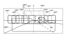
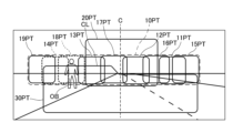
- FIG. 8 is a diagram showing a light distribution pattern in the second dimming state.
- the control unit 40 controls the first light source unit 10LS of the first light source unit 10 to dim or turn off the light source unit forming the light distribution pattern overlapping the object OB.
- the object OB is a pedestrian, and the position of the object OB overlaps with the light distribution patterns 18PT, 14PT formed by the light from the light source units 18, 14. Therefore, the control unit 40 dims or turns off the light emitting elements 18L, 14L of the light source units 18, 14.
- the vehicle headlamp 1R also performs a similar operation, but the light source unit of the first light source unit 10 that emits light in a light distribution pattern that overlaps the object OB is different from the light source units 18, 14 of the first light source unit 10 of the vehicle headlamp 1L. Therefore, in this step, in the vehicle headlamp 1R, the control unit 40 dims or turns off the light source units different from the light source units 18, 14 of the first light source unit 10. After this step, the control unit 40 returns the control flow to step S1.
- the upper light source unit 10U has a plurality of light source units 15-19 arranged side by side, each including reflectors 15R-19R that reflect light emitted from the light source units 15-19L, and a lower light source unit 10L in which light distribution patterns 15PT-19PT formed by the light emitted from the light source units 15-19 are arranged in the left-right direction, and the light distribution patterns 11PT-14PT formed by the light emitted from the light source units 11-14 of the upper light source unit 10U and the light distribution patterns 15PT-19PT formed by the light emitted from the light source units 15-19 of the lower light source unit 10L overlap in the left-right direction.
- the first light source section 10LS of the first light source unit 10 which emits light of a light distribution pattern overlapping in the left-right direction, is divided into an upper light source section 10U and a lower light source section 10L.
- the position where the light distribution patterns of the light emitted from each of the light source sections located on the upper and lower sides overlap in the left-right direction can be set to a desired position. Therefore, according to this vehicle headlamp 1L, 1R, it is possible to brighten a desired position in the left-right direction in the first additional light distribution pattern 10PT above the low-beam light distribution pattern 30PT.
- the first additional light distribution pattern 10PT is located on the left-right end side of the first additional light distribution pattern 10PT based on the left-right central axis C of the low beam light distribution pattern 30PT, and the predetermined light distribution pattern 14PT due to the light irradiated by the predetermined light-emitting element 14L and the light distribution patterns 19PT, 18PT due to the light emitted by the light-emitting elements 19L, 18L other than the predetermined light-emitting element 14L overlap in the left-right direction, and the predetermined light distribution pattern 14PT is located on the left-right end side of the first additional light distribution pattern 10PT based on the left-right central axis C of the low beam light distribution pattern 30PT.
- the vehicle headlamps 1L, 1R of this embodiment also include a second light source unit 20 that emits light that overlaps with a portion of the first additional light distribution pattern 10PT and forms a second additional light distribution pattern 20PT in an area including the central axis C at the upper end of the low beam light distribution pattern 30PT and above the low beam light distribution pattern 30PT.
- the second additional light distribution pattern 20PT can be part of the light distribution pattern of the additional high beam portion together with the first additional light distribution pattern 10PT, and can brighten the upper area including the central axis C in the left-right direction of the low beam light distribution pattern 30PT.
- the vehicle headlamp set 1 of this embodiment also includes a vehicle headlamp 1L arranged on the left side of the vehicle VE and a vehicle headlamp 1R arranged on the right side of the vehicle VE, and the first additional light distribution pattern 10PT formed by the light emitted by the left vehicle headlamp 1L and the first additional light distribution pattern 10PT formed by the light emitted by the right vehicle headlamp 1R overlap with each other. Therefore, the left and right vehicle headlamp 1L, 1R can make the first additional light distribution pattern 10PT brighter than the overlapping area.
- FIG. 9 is a diagram showing, in a manner similar to FIG. 2, how the first additional light distribution pattern 10PT formed by light emitted from the first light source unit 10 of the vehicle headlight 1L and the first additional light distribution pattern 10PT formed by light emitted from the first light source unit 10 of the vehicle headlight 1R overlap in this modified example. Note that, even in this modified example, the first additional light distribution pattern 10PT formed by light emitted from the first light source unit 10 of the vehicle headlight 1L and the first additional light distribution pattern 10PT formed by light emitted from the first light source unit 10 of the vehicle headlight 1R are generally symmetrical.
- the specific light distribution pattern is light distribution pattern 14PT
- light distribution pattern 18PT and light distribution pattern 13PT overlap each other in the specified light distribution pattern 14PT. That is, there is an area where light distribution pattern 14PT, light distribution pattern 18PT, and light distribution pattern 13PT overlap each other.
- light distribution pattern 19PT and light distribution pattern 18PT overlap each other in the specified light distribution pattern 14PT. That is, there is an area where light distribution pattern 14PT, light distribution pattern 19PT, and light distribution pattern 18PT overlap each other.
- at least a portion of each light distribution pattern due to light emitted by two or more light-emitting elements other than the specified light-emitting element overlaps each other in the specified light distribution pattern 14PT.
- light distribution patterns due to light emitted by three or more light-emitting elements including the specified light distribution pattern 14PT overlap. Therefore, the left and right end sides of the first additional light distribution pattern 10PT can be brighter.
- FIG. 10 is a diagram showing the relationship of the first additional light distribution pattern 10PT emitted from the left and right vehicle headlights 1L, 1R in this modified example in a manner similar to that of FIG. 5.
- a part of the first additional light distribution pattern 10PT by the light emitted by the right vehicle headlight 1R is located in the gap S of the first additional light distribution pattern 10PT by the light emitted by the left vehicle headlight 1L
- a part of the first additional light distribution pattern 10PT by the light emitted by the left vehicle headlight 1L is located in the gap S of the first additional light distribution pattern 10PT by the light emitted by the right vehicle headlight 1R.
- the first additional light distribution patterns 10PT emitted by the left and right vehicle headlights 1L, 1R complement each other in the gap S, thereby suppressing a decrease in forward visibility for the occupants of the vehicle VE.
- the light distribution patterns produced by the light emitted by three or more light-emitting elements other than the given light-emitting element 14L may overlap each other.
- the present invention has been described above using the above-mentioned embodiment and modified examples as examples, but the present invention is not limited to these.
- the present invention can be modified from the above-mentioned embodiment and modified examples as long as the amount of overlap between the specified light distribution pattern and the light distribution pattern due to light emitted by some of the light-emitting elements other than the specified light-emitting element is greater than the amount of overlap between the specific light distribution pattern and the light distribution pattern due to light emitted by some of the light-emitting elements other than the specific light-emitting element, and the control unit 40 can dim or turn off the specified light-emitting element.
- the first light source unit 10LS is divided into an upper light source unit 10U and a lower light source unit 10L.
- the present invention is not limited to this, and the multiple light source units 11 to 19 of the first light source unit 10LS may be arranged in a row.
- the second light source unit 20 is not an essential component.
- the light distribution pattern of the additional high beam portion that is added to the low beam light distribution pattern 30PT to form the high beam light distribution pattern is composed of the first additional light distribution pattern 10PT, and the low beam light distribution pattern 30PT and the first additional light distribution pattern 10PT form the high beam light distribution pattern.
- next step is different depending on whether or not the object is located at a position overlapping the second additional light distribution pattern 20PT in step S8.
- the present invention is not limited to the above embodiment, and the next step may be the same regardless of whether or not the object is located at a position overlapping the second additional light distribution pattern 20PT.
- step S9 may be proceeded to after step S7.
- the first dimming state is achieved regardless of whether or not the object is located at a position overlapping the second additional light distribution pattern 20PT. Therefore, the light forming the second additional light distribution pattern 20PT is dimmed or turned off, and the light forming the light distribution pattern overlapping the object in the first additional light distribution pattern 10PT is dimmed or turned off.
- the light of the first additional light distribution pattern 10PT irradiated to the object OB is dimmed, thereby suppressing the irradiation of light to the object OB, and the second additional light distribution pattern 20PT is dimmed or turned off, thereby further suppressing dazzling to oncoming vehicles and pedestrians.
- the process may proceed to step S10 after step S7.
- the second dimming state is entered regardless of whether or not an object is located at a position overlapping the second additional light distribution pattern 20PT. Therefore, the light forming the second additional light distribution pattern 20PT is not particularly changed, and the light forming the light distribution pattern in the first additional light distribution pattern 10PT that overlaps with the object is dimmed or turned off.
- the light of the first additional light distribution pattern 10PT irradiated to the object OB is dimmed, so that the irradiation of light to the object OB can be suppressed, and the second additional light distribution pattern 20PT does not change, so that the area ahead of the vehicle VE can be kept bright.
- the light distribution patterns of the light emitted from the upper light source unit 10U are separated in the left-right direction, and the gaps between the separated light distribution patterns are filled by the light distribution pattern of the light emitted from the lower light source unit 10L, and the light distribution patterns of the light emitted from the lower light source unit 10L are separated in the left-right direction, and the gaps between the separated light distribution patterns are filled by the light distribution pattern of the light emitted from the upper light source unit 10U.
- the light distribution patterns of the light emitted from the upper light source unit 10U do not have to be separated in the left-right direction, and the light distribution patterns of the light emitted from the lower light source unit 10L do not have to be separated in the left-right direction.
- the light source units 11 to 14 of the upper light source unit 10U and the light source units 15 to 19 of the lower light source unit 10L do not need to be misaligned in the left-right direction.
- the first additional light distribution pattern 10PT formed by the light emitted from the left vehicle headlight 1L and the first additional light distribution pattern 10PT formed by the light emitted from the right vehicle headlight 1R are symmetrical in the left-right direction, but these first additional light distribution patterns 10PT do not have to be symmetrical with each other in the left-right direction.
- the light source units 11-14 of the upper light source unit 10U and the light source units 15-19 of the lower light source unit 10L are PES type light source units.
- at least one light source unit may have a configuration other than the PES type having a light emitting element and a reflector.
- all of the light source units 15-19 may be parabolic types having a light emitting element and a reflector. In this case, the projection lens 10PL is not necessary.
- the present invention provides a vehicle headlamp and a vehicle headlamp set that can reduce dazzle for occupants of oncoming vehicles and pedestrians while allowing occupants of one's own vehicle to easily recognize oncoming vehicles and pedestrians, and can be used in fields such as vehicle headlamp applications for automobiles, etc.
Landscapes
- Engineering & Computer Science (AREA)
- Mechanical Engineering (AREA)
- Lighting Device Outwards From Vehicle And Optical Signal (AREA)
- Non-Portable Lighting Devices Or Systems Thereof (AREA)
Abstract
車両用前照灯(1L),(1R)は、ロービーム光源ユニット(30)と、複数の発光素子(11L)~(19L)を有し、ロービーム配光パターン(30PT)の上端及びそれよりも上側を含む領域に第1付加配光パターン(10PT)を形成する光を出射する第1光源ユニット(10)と、制御部(40)と、を備え、中心軸(C)を基準とした第1付加配光パターン(10PT)の左右方向の端部側に位置する所定の配光パターン(14PT)と他の配光パターン(19PT),(18PT)との重なり量は、所定の配光パターン(14PT)よりも中心軸(C)側に位置する特定の配光パターン(17PT)と他の配光パターン(13PT),(12PT)との重なり量よりも大きく、制御部(40)は、所定の発光素子(14L)を減光または消灯可能である。
Description
本発明は、車両用前照灯、及び車両用前照灯セットに関する。
自車両の前方に位置する他車両を検出する検出装置からの情報に基づいて、出射する光の配光パターンを変化させる車両用前照灯が知られている。下記特許文献1には、このような車両用前照灯が記載されている。
下記特許文献1に記載の車両用前照灯は、左右の車両用前照灯においてそれぞれ横一列に配置される複数のLED(Light Emitting Diode)から出射する光の光量を個別に変更することで、自車両の前方に位置する他車両にハイビームの光が照射されることを抑制している。このように、自車両の前方に位置する他車両等以外の部分にハイビームの光を照射しつつ、当該他車両等にハイビームの光を照射することを抑制する技術をADB(Adaptive Driving Beam)と呼ぶ場合がある。
一般にハイビーム配光パターンは、ロービーム配光パターン上端及びその上側に照射される付加ハイビーム部分の配光パターンがロービーム配光パターンに加えれることで形成される。この付加ハイビーム部分の配光パターンは、一般的に左右方向の中心軸側程高い輝度とされている。別言すれば、付加ハイビーム部分の配光パターンは、左右方向の端部側の輝度が中心軸側の輝度よりも低い。
ところで、先行車は、自車両の正面に位置し、自車両と共に走行するため、自車両の乗員の視界に入りやすく、視認時間が長いため、乗員は先行車を認識し易い。しかし、対向車や歩行者は、自車両の正面から左右方向にずれた領域に位置し、視認時間が短いため、乗員は、先行車と比べて、対向車や歩行者を認識し難い。特に夕刻や明け方といった薄暗い環境では、対向車が前照灯を消灯している場合があり、乗員は他車両を認識し難い。そこで、付加ハイビーム部分の配光パターンにおける左右方向の端部側の輝度が中心軸側の輝度よりも高くされることが考えられる。しかし、この場合、対向車の乗員や歩行者に幻惑を与える懸念がある。
そこで、本発明は、対向車の乗員や歩行者への幻惑を抑制しつつ、自車の乗員が対向車や歩行者を認識し易い車両用前照灯、及び車両用前照灯セットを提供することを目的とする。
上記目的の達成のため、本発明の車両用前照灯は、ロービーム配光パターンを形成する光を出射するロービーム光源ユニットと、複数の発光素子を有し、前記ロービーム配光パターンの上端及び前記ロービーム配光パターンよりも上側を含む領域に第1付加配光パターンを形成する光を出射する第1光源ユニットと、制御部と、を備え、前記ロービーム配光パターンの左右方向の中心軸を基準とした第1付加配光パターンの左右方向の端部側に位置し、所定の前記発光素子が照射する光による所定の配光パターンと、前記所定の発光素子以外の前記発光素子の一部が出射する光による配光パターンとは、左右方向において重なり、前記第1付加配光パターンにおいて前記所定の配光パターンよりも前記中心軸側に位置し、特定の前記発光素子が照射する光による特定の配光パターンと、前記特定の発光素子以外の前記発光素子の一部が出射する光による配光パターンとは、左右方向において重なり、前記所定の配光パターンと前記所定の発光素子以外の前記発光素子の一部が出射する光による配光パターンとの重なり量は、前記特定の配光パターンと前記特定の発光素子以外の前記発光素子の一部が出射する光による配光パターンとの重なり量よりも大きく、前記制御部は、前記所定の発光素子を減光または消灯可能であることを特徴とするものである。
第1付加配光パターンは、ロービーム配光パターンと合わせてハイビーム配光パターン形成する付加ハイビーム部分の配光パターンの少なくとも一部と成り得る。この車両用前照灯では、所定の配光パターンと所定の発光素子以外の発光素子の一部が出射する光による配光パターンとの重なり量が、特定の配光パターンと特定の発光素子以外の前記発光素子の一部が出射する光による配光パターンとの重なり量よりも大きい。従って、第1付加配光パターンにおける左右方向の端部側が所定の配光パターンの領域内が、第1付加配光パターンにおける左右方向の中心側に位置する特定の配光パターンの領域内よりも明るくされ得る。このため、この車両用前照灯によれば、自車両の乗員が対向車や歩行者を認識し易くし得る。また、この車両用前照灯では、制御部が、所定の配光パターンを形成する光を減光または消灯可能なため、対向車の乗員や歩行者への幻惑を抑制し得る。
また、前記所定の配光パターン内において、前記所定の発光素子以外の2以上の前記発光素子が出射する光によるそれぞれの配光パターンの少なくとも一部が互いに重なることが好ましい。
この場合、2以上の発光素子が出射する光によるそれぞれの配光パターンと所定の配光パターンとが重なる。つまり、所定の配光パターンを含む3以上の発光素子が出射する光による配光パターンが重なる。従って、第1付加配光パターンにおける左右方向の端部側をより明るくし得る。
また、前記第1付加配光パターンの一部と重なり前記ロービーム配光パターンの上端及び前記ロービーム配光パターンよりも上側において前記中心軸を含む領域に第2付加配光パターンを形成する光を出射する第2光源ユニットを更に備えることが好ましい。
この場合、第2付加配光パターンは、第1付加配光パターンと合わせて付加ハイビーム部分の配光パターンの一部と成り得、ロービーム配光パターンの左右方向の中心軸を含む上方の領域をより明るくし得る。
また、前記所定の配光パターンが前記第2付加配光パターンと重なってもよい。
或いは、第2付加配光パターンは、前記特定の配光パターンの少なくとも一部と重なり、前記所定の配光パターンと重ならなくてもよい。
この場合、所定の配光パターン内よりも暗くなり得る特定の配光パターン内を、第2付加配光パターンにより明るくし得る。
また、前記制御部は、前記所定の発光素子を減光または消灯させるとき、前記第2光源ユニットを減光または消灯させることが好ましい。
対向車や歩行者に照射され得る所定の配光パターンを形成する光が減光または消灯される際、第2付加配光パターンを形成する光も減光または消灯されるため、第2付加配光パターンを形成する光による対向車の乗員や歩行者への幻惑を抑制し得る。特に、上記のように、第2付加配光パターンが所定の配光パターンの少なくとも一部と重なる場合、第2付加配光パターンを形成する光による対向車の乗員や歩行者への幻惑をより効果的に抑制し得る。
また、前記第1付加配光パターンは、第2付加配光パターン内において、左右方向に離隔してもよい。
この場合、第1付加配光パターンの隙間に照射する発光素子が不要であるため、発光素子の数を減らし得る。その一方、第2付加配光パターンを形成する光が、当該隙間を照射するため、自車両の乗員の前方の視認性が低下することを抑制し得る。
また、本発明の車両用灯具セットは、車両の左側に配置される請求項1から7のいずれか1項の車両用前照灯と、車両の右側に配置される上記のいずれかの車両用前照灯と、を備え、左側の前記車両用前照灯が出射する光による前記第1付加配光パターンの少なくとも一部と、右側の前記車両用前照灯が出射する光による前記第1付加配光パターンの少なくとも一部とは、互いに重なることを特徴とするものである。
この場合、左右の車両用前照灯により、第1付加配光パターンが重なる領域より明るくし得る。
また、左側の前記車両用前照灯が出射する光による前記第1付加配光パターンと、右側の前記車両用前照灯が出射する光による前記第1付加配光パターンとは、概ね左右対称であることが好ましい。
この場合、左右の車両用前照灯により、第1付加配光パターンにおける左右方向の両端部側に位置するそれぞれの所定の配光パターンを明るくし得る。一般的に対向車と歩行者は、自車両の左右方向の逆側に位置する。従って、この構成によれば、自車両の乗員が対向車及び歩行者の双方を認識し易くし得る。
また、左側の前記車両用前照灯が出射する光による前記第1付加配光パターンは、左右方向に2以上に離隔し、右側の前記車両用前照灯が出射する光による前記第1付加配光パターンは、左右方向に2以上に離隔し、左側の前記車両用前照灯が出射する光による前記第1付加配光パターンの隙間に右側の前記車両用前照灯が出射する光による前記第1付加配光パターンの一部が位置し、右側の前記車両用前照灯が出射する光による前記第1付加配光パターンの隙間に左側の前記車両用前照灯が出射する光による前記第1付加配光パターンの一部が位置することが好ましい。
この場合、左右の車両用前照灯において、第1付加配光パターンの隙間に照射する発光素子が不要であるため、発光素子の数を減らし得る。また、一方の車両用前照灯のよる第1付加配光パターンが、他方の第1付加配光パターンの隙間に重なるため、自車両の乗員の前方の視認性が低下することを抑制し得る。
以上のように本発明によれば、対向車の乗員や歩行者への幻惑を抑制しつつ、自車の乗員が対向車や歩行者を認識し易い車両用前照灯、及び車両用前照灯セットが提供され得る。
以下、本発明に係る車両用前照灯及び車両用前照灯セットを実施するための形態が添付図面とともに例示される。以下に例示する実施形態は、本発明の理解を容易にするためのものであり、本発明を限定して解釈するためのものではない。本発明は、請求項の範囲内において、その趣旨を逸脱することなく、以下の実施形態から変更、改良することができる。
まず、本実施形態の車両用前照灯の構成について説明する。
図1は、本実施形態の車両用前照灯セットを備える車両を示す概略図である。図1に示すように車両VEは、車両用前照灯セット1と、ECU(Electronic Control Unit)3と、検知装置4とを備える。
車両用前照灯セット1は、車両VEの前方に配置される右側の車両用前照灯1Rと、車両VEの前方に配置される左側の車両用前照灯1Lとを備える。本実施形態では、右側の車両用前照灯1Rと左側の車両用前照灯1Lとは、互いに左右方向に概ね対称である点を除き、概ね同様の構成である。このため以下では、左側の車両用前照灯1Lについて主に説明する。なお、本実施形態において、右側及び左側とは、車両VEの進行方向を向く場合における右側及び左側を指す。
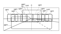
図2は、本実施形態の左側の車両用前照灯1Lが出射する光により形成される配光パターンを示す図である。図2に示すように、本実施形態では、車両用前照灯1Lが出射する光により、ロービーム配光パターン30PTと、破線で囲われる第1付加配光パターン10PTと、第2付加配光パターン20PTと、が形成される。ロービーム配光パターン30PTは、車両VEの前方下側に照射される光により形成される配光パターンであり、ロービーム配光パターン30PTの上端であるカットラインCLを有する。第1付加配光パターン10PTは、ロービーム配光パターン30PTの上端及びロービーム配光パターン30PTよりも上側の領域に位置する配光パターンである。第1付加配光パターン10PTの詳細は後述される。第2付加配光パターン20PTは、第1付加配光パターン10PTの一部と重なる配光パターンであり、ロービーム配光パターン30PTの上端及びロービーム配光パターン30PTよりも上側においてロービーム配光パターン30PTの左右方向の中心軸Cを含む領域に位置する。本実施形態では、第1付加配光パターン10PT及び第2付加配光パターン20PTにより、付加ハイビーム部分の配光パターンが形成される。この付加ハイビーム部分の配光パターンは、ロービーム配光パターン30PTに付加されることでハイビーム配光パターンを形成する。つまり、図2に示される配光パターン全体は、ハイビーム配光パターンの一例である。なお、配光パターンとは、例えば、車両の前方に位置する鉛直な面に、それぞれの車両用前照灯1L,1Rから照射される光により描かれる光のパターンであり、光の外形の他に、光の強度分布を含む。それぞれの車両用前照灯1L,1Rからの光が照射される面は、例えば、車両の25m前方に位置する。
図1に戻り、車両用前照灯1Lは、ロービーム配光パターンを形成する光を出射するロービーム光源ユニット30と、第1付加配光パターンの光を出射する第1光源ユニット10と、第2付加配光パターンの光を出射する第2光源ユニット20と、制御部40と、筐体50と、を備える。
筐体50は、ランプハウジング51、フロントカバー52を主な構成要素として備える。ランプハウジング51の前方は開口しており、当該開口を塞ぐようにフロントカバー52がランプハウジング51に固定されている。ランプハウジング51と、当該ランプハウジング51の前方の開口を塞ぐフロントカバー52とによって形成される空間内にロービーム光源ユニット30、第1光源ユニット10、及び第2光源ユニット20が収容されている。制御部40は、筐体50の空間内に配置されても、当該空間内に配置されなくてもよい。なお、図1の例では、ロービーム光源ユニット30、第1光源ユニット10、及び第2光源ユニット20が筐体50の空間内に収容されているが、ロービーム光源ユニット30、第1光源ユニット10、及び第2光源ユニット20がそれぞれ別の筐体内に収容されてもよい。
ロービーム光源ユニット30は、例えば、PES(Projector Ellipsoid System)型の光源ユニットであり、ロービーム光源部30LSと、投影レンズ30PLとを有する。ロービーム光源ユニット30がPES型である場合、ロービーム光源部30LSは、例えば、発光素子と、当該発光素子から出射する光を反射するリフレクタと、シェードと、を有する。発光素子は、例えば上方に光を出射し、リフレクタは、当該光を前方の投影レンズ30PLに向けて反射し、シェードは、反射した光の一部をカットして、ロービーム配光パターンのカットラインCLを形成する。投影レンズ30PLは、入射する光の発散角を整えて、ロービーム配光パターン30PTを形成する光を出射する。
なお、ロービーム光源ユニット30は、PES型に限らず、直射型や、パラボラ型であってもよい。ロービーム光源ユニット30が直射型の場合、ロービーム光源部30LSは、例えば、発光素子と、シェードと、を有し、発光素子から出射する光の一部が、シェードでカットされ、他の光が投影レンズ30PLに入射する。ロービーム光源ユニット30がパラボラ型の場合、ロービーム光源ユニット30は、投影レンズ30PLを備えなくてもよい。この場合、ロービーム光源ユニット30は、発光素子と、当該発光素子から出射する光を反射するリフレクタと、を有し、リフレクタは、例えば、カットラインを生成するように、光を反射する。なお、ロービーム光源ユニット30は、ロービーム配光パターン30PTの光を出射する限りにおいて、上記構成以外の構成であってもよい。
第2光源ユニット20は、例えば、シェード等のカットラインを生成する部位を備えない点において、ロービーム光源ユニット30と同様の構成であり、図1の例では、第2光源ユニット20は、第2光源部20LS及び投影レンズ20PLを有する。ただし、第2光源ユニット20の光学的設計は、第2付加配光パターン20PTの光を出射する点において、ロービーム光源ユニット30と異なる。なお、第2光源ユニット20は、第2付加配光パターン20PTの光を出射する限りにおいて、ロービーム光源ユニット30と異なる構成であってもよい。
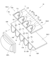
図3は、第1光源ユニット10の分解斜視図である。図1、図3に示すように、本実施形態では、第1光源ユニット10は、第1光源部10LS及び投影レンズ10PLを有する。第1光源部10LSは、上側光源部10Uと下側光源部10Lを有する。
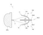
上側光源部10Uは、基板10UCと、基板10UCの上面上に設けられ、左右方向に横並びに配置される複数の光源部11~14とを有する。光源部11は、発光素子11Lと、リフレクタ11Rとを有する。図4は、第1光源ユニット10の断面図である。図4に示すように、発光素子11Lは、上方に光を出射し、リフレクタ11Rは、発光素子11Lからの光を投影レンズ10PLに向けて反射する。この際、リフレクタ11Rからの光は、投影レンズ10PLの焦点Fにおいて集光する。このように光が伝搬するように、リフレクタ11Rの反射面は形成されている。他の光源部12~14は、発光素子12L~14Lと、リフレクタ12R~14Rを有し、光源部11と同様の構成である。つまり、上側光源部10Uは、発光素子11L~14L及び発光素子11L~14Lを上側から覆うリフレクタ11R~14Rを含む複数のPES型光源を含む。なお、投影レンズ10PLは、上側光源部10Uから出射する光を透過する。
下側光源部10Lは、基板10LCと、基板10UCの下面上に設けられ、左右方向に横並びに配置される複数の光源部15~19とを有する。光源部15は、発光素子15Lと、リフレクタ15Rとを有する。図4に示すように、発光素子15Lは、下方に光を出射し、リフレクタ15Rは、発光素子15Lからの光を投影レンズ10PLに向けて反射する。この際、リフレクタ15Rからの光は、投影レンズ10PLの焦点Fにおいて集光する。このように光が伝搬するように、リフレクタ15Rの反射面が形成されている。他の光源部16~19は、発光素子16L~19Lと、リフレクタ16R~19Rを有し、光源部15と同様の構成である。つまり、下側光源部10Lは、発光素子15L~19L及び発光素子15L~19Lを下側から覆うリフレクタ15R~19Rを含む複数のPES型光源を含む。なお、投影レンズ10PLは、下側光源部10Lから出射する光を透過する。
また、本実施形態では、上側光源部10Uの光源部11~14と下側光源部10Lの光源部15~19とは、左右方向にずれている。本例では、光源部19が最も左側に位置し、光源部15が最も右側に位置する。本実施形態では、上側光源部10Uの光源部11~14と、下側光源部10Lの光源部15~19とが、上下方向に位置がずれた状態で、左右方向に交互に並んでいる。このため、発光素子19Lと発光素子18Lとの左右方向の間に発光素子14Lが位置し、発光素子18Lと発光素子17Lとの左右方向の間に発光素子13Lが位置し、発光素子17Lと発光素子16Lとの左右方向の間に発光素子12Lが位置し、発光素子16Lと発光素子15Lとの左右方向の間に発光素子11Lが位置する。このように、上側光源部10Uの光源部11~14と下側光源部10Lの光源部15~19とが左右方向にずれることで、上側光源部10Uの光源部11~14から出射する光による配光パターン11PT~14PTと、下側光源部10Lの光源部15~19から出射する光による配光パターン15PT~19PTとを、左右方向にずらしやすい。なお、図4では、理解容易にするため、光源部11~14と光源部15~19との左右方向のずれを無視している。
図1に戻り、制御部40は、ロービーム光源ユニット30のロービーム光源部30LS、第2光源ユニット20の第2光源部20LS、及び第1光源ユニット10の第1光源部10LSと、電気的に接続されている。制御部40は、例えば、マイクロコントローラ、IC(Integrated Circuit)、LSI(Large-scale Integrated Circuit)、ASIC(Application Specific Integrated Circuit)などの集積回路やNC(Numerical Control)装置等から成る。また、制御部40は、機械学習器を用いたものであってもよく、機械学習器を用いないものであってもよい。制御部40は、ECU3にも電気的に接続されている。
ECU3は、例えば制御部40と概ね同様の構成であり、車両用前照灯1L,1Rに情報を供給する。なお、ECU3は、エンジン制御、エアバッグ制御、トランスミッション制御等を行ってもよい。
検知装置4は、画像取得部4Aと、判定部4Dと、を有し、車両VEの前方に位置する歩行者や他車両といった対象物を検知する装置である。他車両には、前走車及び対向車が含まれる。画像取得部4Aは、例えば、LiDAR(Light Detection And Ranging)、カメラ等から成る。画像取得部4AがLiDARである場合、画像取得部4Aは、例えば、車両VEの前方をレーザ光で走査し、反射により戻るレーザ光を受光して、受光したレーザ光に基づき画像に係る信号を生成し、当該信号を判定部4Dに出力する。画像取得部4Aがカメラから成る場合、カメラとしては、例えば、CCD(Charged Coupled Device)カメラ、CMOS(Complementary Metal Oxide Semiconductor)カメラを挙げることができる。この場合、画像取得部4Aは、車両VEの前方を撮影し、撮影した画像に係る信号を判定部4Dに出力する。判定部4Dは、ECU3に電気的に接続されており、例えば制御部40と概ね同様の構成であり、画像取得部4Aから入力する画像に係る信号に対象物の画像が含まれるかを判定する。判定部4Dは、画像に係る信号に対象物の画像が含まれる場合、対象物の位置座標を算出する。判定部は、対象物の画像が含まれる場合、対象物の位置座標に係るデータを含む信号は、ECU3に出力される。
次に、第1付加配光パターン10PTについて、より詳細に説明する。
図2に示す第1付加配光パターン10PTの配光パターン11PTは、光源部11から出射する光による配光パターンであり、同様に配光パターン12PT~19PTは、それぞれ光源部12~19から出射する光による配光パターンである。本実施形態では、車両用前照灯1Lの第1光源ユニット10から出射する光による第1付加配光パターン10PTの中心は、ロービーム配光パターン30PTの左右方向の中心軸Cよりも左側にずれている。
図2に示すように、上側光源部10Uの光源部11~14が出射し、投影レンズ10PLを透過する光による配光パターン11PT~14PTと、下側光源部10Lの光源部15~19が出射し、投影レンズ10PLを透過する光による配光パターン15PT~19PTとは、左右方向に一部重なっている。本実施形態では、配光パターン11PT~19PTが、光源部11~19の左右方向の並び方と同様に並んでいる。つまり、上側光源部10Uの光源部11~14から出射する光によるそれぞれの配光パターン11PT~14PTと、下側光源部10Lの光源部15~19から出射する光によるそれぞれの配光パターン15PT~19PTとは、互いに一部が重なりつつ左右方向に交互に並んでいる。このため、上側光源部10Uから出射する光による配光パターンと、下側光源部10Lから出射する光による配光パターンとが、互いに一部が重なりつつ左右方向に交互に並ぶ区間を明るくし得る。
上記のように配光パターン11PT~19PTが交互に並ぶため、上側光源部10Uから出射する光による配光パターン11PT~14PTは、それぞれ左右方向に離隔し、下側光源部10Lから出射する光による配光パターン16PT~18PTは、上側光源部10Uから出射する光による離隔した配光パターン11PT~14PTの少なくとも一部に重なると共に、離隔したそれぞれの配光パターン11PT~14PTの隙間を埋めている。また、下側光源部10Lから出射する光による配光パターン15PT~19PTは、それぞれ左右方向に離隔し、上側光源部10Uから出射する光による配光パターン11PT~14PTは、下側光源部10Lから出射する光による離隔した配光パターン15PT~19PTの少なくとも一部に重なると共に、離隔したそれぞれの配光パターン15PT~19PTの隙間を埋めている。このように、上側光源部10Uから出射する光による互いに離隔した配光パターンの間に下側光源部10Lから出射する光による配光パターンが位置したり、下側光源部10Lから出射する光による互いに離隔した配光パターンの間に上側光源部10Uから出射する光による配光パターンが位置することで、第1付加配光パターン10PTにおける左右方向の端部以外の位置を明るくし得る。
ここで、ロービーム配光パターン30PTの中心軸Cを基準として、第1付加配光パターン10PTの左右方向の端部側に位置する配光パターン14PTを所定の配光パターン14PTとし、所定の配光パターン14PTを形成する光を出射する光源部を所定の光源部14とし、所定の光源部14の発光素子を所定の発光素子14Lとする。この場合、所定の配光パターン14PTは、所定の発光素子14L以外の発光素子19L,18Lが出射する光による配光パターン19PT,18PTと、左右方向において重なる。
また、第1付加配光パターン10PTにおいて所定の配光パターン14PTよりも中心軸C側に位置する配光パターン17PTを特定の配光パターン17PTとし、特定の配光パターン17PTを形成する光を出射する光源部を特定の光源部17とし、特定の光源部17の発光素子を特定の発光素子17Lとする。この場合、特定の配光パターン17PTは、特定の発光素子17L以外の発光素子13L,12Lが出射する光による配光パターン13PT,12PTと、左右方向において重なる。
このように所定の配光パターンを配光パターン14PTとし、特定の配光パターンを配光パターン17PTとすると、所定の配光パターン14PTと所定の発光素子14L以外の発光素子19L,18Lが出射する光による配光パターン19PT,18PTとの重なり量は、特定の配光パターン17PTと特定の発光素子17L以外の発光素子13L,12Lが出射する光による配光パターン13PT,12PTとの重なり量よりも大きい。この関係は、例えば、特定の配光パターンを配光パターン13PTや配光パターン14PTとしても同様である。また、所定の配光パターンを配光パターン11PTとしても同様である。或いは、所定の配光パターンを配光パターン18PT或いは配光パターン16PTとし、特定の配光パターンを配光パターン17PT、配光パターン13PT、或いは配光パターン12PTとしても同様である。つまり、本実施形態の第1付加配光パターン10PTの場合、第1付加配光パターン10PTの左右方向の端部側に位置する所定の配光パターンと所定の発光素子以外の発光素子の一部が出射する光による配光パターンとの重なり量は、所定の配光パターンよりも中心軸C側に位置する特定の配光パターンと特定の発光素子以外の発光素子の一部が出射する光による配光パターンとの重なり量よりも大きい。従って、特定の配光パターンの領域内は所定の配光パターンの領域内よりも明るくされ得る。
本実施形態の場合、上側光源部10Uおよび下側光源部10Lの一方は、所定の発光素子を含み、上側光源部10Uおよび下側光源部10Lの他方は、所定の配光パターンと重なる配光パターンを形成する光を出射する発光素子を含む。このように、所定の配光パターンを出射する発光素子と、所定の配光パターンに重なる配光パターンの光を出射する発光素子とは、上側光源部10Uと下側光源部とに分かれることで、所定の配光パターンにおける重なり量をより大きくし得、所定の配光パターンをより明るくし得る。
また、所定の配光パターンを配光パターン14PTとし、特定の配光パターンを配光パターン17PTや配光パターン13PTとする場合、所定の配光パターン14PTは、第2付加配光パターン20PTと重ならず、特定の配光パターン17PT,13PTは、第2付加配光パターン20PTと重なる。このように、第2付加配光パターン20PTが特定の配光パターン17PT,13PTの少なくとも一部と重なり、所定の配光パターン14PTと重ならない場合、所定の配光パターン14PT内よりも暗くなり得る特定の配光パターン17PT,13PT内を、第2付加配光パターン20PTにより明るくし得る。なお、所定の配光パターンを配光パターン16PTとすれば、所定の配光パターン16PT及び特定の配光パターン12PT,17PTは、共に第2付加配光パターン20PTと重なる。
なお、第2付加配光パターン20PTは、図2に示すように、第1付加配光パターン10PTと重なる領域の他、第1付加配光パターン10PTの上方の領域に形成されることが好ましい。この場合、自車両の正面の高い位置に設置される標識灯を明るくし得る。
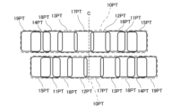
図5は、左右の車両用前照灯1L,1Rから出射する第1付加配光パターン10PTの関係を示す図である。なお、本図では、図が複雑化されることを防ぐため、左側の車両用前照灯1Lから出射する第1付加配光パターン10PTが、右側の車両用前照灯1Rから出射する第1付加配光パターン10PTの上側に記載されているが、左側の車両用前照灯1Lから出射する第1付加配光パターン10PTと、右側の車両用前照灯1Rから出射する第1付加配光パターン10PTとは、概ね同じ高さに形成される。
本実施形態では、上記のように車両用前照灯1Lと車両用前照灯1Rとは、概ね左右対称の構成である。このため、車両用前照灯1Lから出射する光による第1付加配光パターンと、車両用前照灯1Rから出射する光による第1付加配光パターンとは、概ね左右対称である。また、上記のように車両用前照灯1Lから出射する光による第1付加配光パターンは、ロービーム配光パターン30PTの左右方向の中心軸Cよりも左側にずれているため、車両用前照灯1Rから出射する光による第1付加配光パターンは、中心軸Cよりも右側にずれている。このように、それぞれの第1付加配光パターンが互いに左右方向にずれた状態で、その一部同士が重なっている。
次に、車両用前照灯セット1の動作について説明する。
図6は、本実施形態における車両用前照灯1Lの制御部40の動作を示すフローチャートである。図6に示すように、本実施形態では、制御部40の動作は、ステップS1からステップS10を備える。なお、特に説明する場合を除き、車両用前照灯1Lと車両用前照灯1Rとは、同様の動作を行う。
(ステップS1)
本ステップは、不図示のライトスイッチからオン信号が入力されているか否かで、次のステップを異ならせるステップである。本ステップにおいて、制御部40は、ライトスイッチからオン信号が入力されていない場合には制御フローをステップS2に進め、オン信号が入力する場合には制御フローをステップS3に進める。なお、ライトスイッチからのオン信号は、制御部40に直接入力してもよく、ECU3を介して入力してもよい。
本ステップは、不図示のライトスイッチからオン信号が入力されているか否かで、次のステップを異ならせるステップである。本ステップにおいて、制御部40は、ライトスイッチからオン信号が入力されていない場合には制御フローをステップS2に進め、オン信号が入力する場合には制御フローをステップS3に進める。なお、ライトスイッチからのオン信号は、制御部40に直接入力してもよく、ECU3を介して入力してもよい。
(ステップS2)
本ステップは、車両用前照灯1Lから光を非出射とさせるステップである。本ステップにおいて、制御部40は、ロービーム光源ユニット30のロービーム光源部30LS、第2光源ユニット20の第2光源部20LS、および第1光源ユニット10の第1光源部10LSを制御して、ロービーム光源部30LS、第2光源部20LS、および第1光源部10LSを光が非出射の状態とする。なお、制御部40がロービーム光源部30LS、第2光源部20LS、および第1光源部10LSを光が非出射の状態とするように制御する場合、結果としてこれら光源部から光が出射しなければよく、制御部40からロービーム光源部30LS、第2光源部20LS、および第1光源部10LSに制御信号が入力されない場合を含む。例えば、ステップS1から本ステップに進む際にロービーム光源部30LS、第2光源部20LS、および第1光源部10LSから光が出射していない場合には、制御部40は、その状態を維持すればよい。従って、この場合、制御部40が何ら制御信号を出力しなくてもよい。本ステップの後、制御部40は、制御フローをステップS1に戻す。
本ステップは、車両用前照灯1Lから光を非出射とさせるステップである。本ステップにおいて、制御部40は、ロービーム光源ユニット30のロービーム光源部30LS、第2光源ユニット20の第2光源部20LS、および第1光源ユニット10の第1光源部10LSを制御して、ロービーム光源部30LS、第2光源部20LS、および第1光源部10LSを光が非出射の状態とする。なお、制御部40がロービーム光源部30LS、第2光源部20LS、および第1光源部10LSを光が非出射の状態とするように制御する場合、結果としてこれら光源部から光が出射しなければよく、制御部40からロービーム光源部30LS、第2光源部20LS、および第1光源部10LSに制御信号が入力されない場合を含む。例えば、ステップS1から本ステップに進む際にロービーム光源部30LS、第2光源部20LS、および第1光源部10LSから光が出射していない場合には、制御部40は、その状態を維持すればよい。従って、この場合、制御部40が何ら制御信号を出力しなくてもよい。本ステップの後、制御部40は、制御フローをステップS1に戻す。
(ステップS3)
本ステップは、ロービーム光源ユニット30からロービーム配光パターン30PTとなる光を出射させるステップである。本ステップにおいて、制御部40は、ロービーム光源ユニット30のロービーム光源部30LSを制御して、ロービーム光源部30LSから光を出射させる。こうして、ロービーム光源部30LSからは、ロービーム配光パターン30PTとなる光が出射する。なお、ステップS2から本ステップに進む際にロービーム光源ユニット30から光が出射している場合には、制御部40は、その状態を維持すればよい。この場合、制御部40は、ロービーム光源ユニット30に何ら制御信号を出力しなくてもよい。また、本ステップにおいて、制御部40は、第2光源ユニット20および第1光源ユニット10を特に制御しない。従って、ステップS2から本ステップに進む際の第2光源ユニット20および第1光源ユニット10からの光の出射の状態が維持される。本ステップの後、制御部40は、制御フローをステップS4に進める。
本ステップは、ロービーム光源ユニット30からロービーム配光パターン30PTとなる光を出射させるステップである。本ステップにおいて、制御部40は、ロービーム光源ユニット30のロービーム光源部30LSを制御して、ロービーム光源部30LSから光を出射させる。こうして、ロービーム光源部30LSからは、ロービーム配光パターン30PTとなる光が出射する。なお、ステップS2から本ステップに進む際にロービーム光源ユニット30から光が出射している場合には、制御部40は、その状態を維持すればよい。この場合、制御部40は、ロービーム光源ユニット30に何ら制御信号を出力しなくてもよい。また、本ステップにおいて、制御部40は、第2光源ユニット20および第1光源ユニット10を特に制御しない。従って、ステップS2から本ステップに進む際の第2光源ユニット20および第1光源ユニット10からの光の出射の状態が維持される。本ステップの後、制御部40は、制御フローをステップS4に進める。
(ステップS4)
本ステップは、不図示のハイビームスイッチからオン信号が入力されているか否かで、次のステップを異ならせるステップである。本ステップにおいて、制御部40は、ハイビームスイッチからオン信号が入力されていない場合には制御フローをステップS5に進め、ハイビームスイッチのオン信号が入力する場合には制御フローをステップS6に進める。なお、ハイビームスイッチからのオン信号は、制御部40に直接入力してもよく、ECU3を介して入力してもよい。
本ステップは、不図示のハイビームスイッチからオン信号が入力されているか否かで、次のステップを異ならせるステップである。本ステップにおいて、制御部40は、ハイビームスイッチからオン信号が入力されていない場合には制御フローをステップS5に進め、ハイビームスイッチのオン信号が入力する場合には制御フローをステップS6に進める。なお、ハイビームスイッチからのオン信号は、制御部40に直接入力してもよく、ECU3を介して入力してもよい。
(ステップS5)
本ステップは、第2光源ユニット20および第1光源ユニット10からの光を非出射、すなわち、ロービーム配光パターンと合わせてハイビーム配光パターンを形成する付加ハイビーム部分の配光パターンとなる光を非出射とするステップである。本ステップにおいて、制御部40は、第2光源ユニット20の第2光源部20LS、および第1光源ユニット10の第1光源部10LSを制御して、第2光源部20LSおよび第1光源部10LSからの光を非出射とする。なお、ステップS4から本ステップに進む際に第2光源ユニット20および第1光源ユニット10から光が出射していない場合には、制御部40は、その状態を維持すればよい。この場合、制御部40が第2光源ユニット20および第1光源ユニット10に何ら制御信号を出力しなくてもよい。本ステップの後、制御部40は、制御フローをステップS1に戻す。
本ステップは、第2光源ユニット20および第1光源ユニット10からの光を非出射、すなわち、ロービーム配光パターンと合わせてハイビーム配光パターンを形成する付加ハイビーム部分の配光パターンとなる光を非出射とするステップである。本ステップにおいて、制御部40は、第2光源ユニット20の第2光源部20LS、および第1光源ユニット10の第1光源部10LSを制御して、第2光源部20LSおよび第1光源部10LSからの光を非出射とする。なお、ステップS4から本ステップに進む際に第2光源ユニット20および第1光源ユニット10から光が出射していない場合には、制御部40は、その状態を維持すればよい。この場合、制御部40が第2光源ユニット20および第1光源ユニット10に何ら制御信号を出力しなくてもよい。本ステップの後、制御部40は、制御フローをステップS1に戻す。
(ステップS6)
本ステップは、第2光源ユニット20および第1光源ユニット10から光を出射させるステップ、すなわち、付加ハイビーム部分の配光パターンとなる光を出射するステップである。本ステップにおいて、制御部40は、第2光源ユニット20の第2光源部20LSおよび第1光源ユニット10の第1光源部10LSを制御して、第2光源部20LSから第2付加配光パターン20PTとなる光を出射させると共に第1光源部10LSから第1付加配光パターン10PTとなる光を出射させる。本ステップでは、既にロービーム光源ユニット30からロービーム配光パターン30PTとなる光が出射しているため、ロービーム配光パターン30PTに第2光源ユニット20及び第1光源ユニット10から出射する光による第2付加配光パターン20PTおよび第1付加配光パターン10PTが付加されて、ハイビーム配光パターンが形成される。こうして、本ステップにおいて、車両用前照灯1Lからハイビーム配光パターンとなる光が出射する。なお、ステップS4から本ステップに進む際に第2光源ユニット20及び第1光源ユニット10から光が出射している場合には、制御部40は、その状態を維持すればよい。この場合、制御部40が第2光源ユニット20及び第1光源ユニット10に何ら制御信号を出力しなくてもよい。本ステップの後、制御部40は、制御フローをステップS7に進める。
本ステップは、第2光源ユニット20および第1光源ユニット10から光を出射させるステップ、すなわち、付加ハイビーム部分の配光パターンとなる光を出射するステップである。本ステップにおいて、制御部40は、第2光源ユニット20の第2光源部20LSおよび第1光源ユニット10の第1光源部10LSを制御して、第2光源部20LSから第2付加配光パターン20PTとなる光を出射させると共に第1光源部10LSから第1付加配光パターン10PTとなる光を出射させる。本ステップでは、既にロービーム光源ユニット30からロービーム配光パターン30PTとなる光が出射しているため、ロービーム配光パターン30PTに第2光源ユニット20及び第1光源ユニット10から出射する光による第2付加配光パターン20PTおよび第1付加配光パターン10PTが付加されて、ハイビーム配光パターンが形成される。こうして、本ステップにおいて、車両用前照灯1Lからハイビーム配光パターンとなる光が出射する。なお、ステップS4から本ステップに進む際に第2光源ユニット20及び第1光源ユニット10から光が出射している場合には、制御部40は、その状態を維持すればよい。この場合、制御部40が第2光源ユニット20及び第1光源ユニット10に何ら制御信号を出力しなくてもよい。本ステップの後、制御部40は、制御フローをステップS7に進める。
(ステップS7)
本ステップは、検知装置4からの信号により、次のステップを異ならせるステップである。本ステップにおいて、制御部40は、検知装置4からの信号が対象物を検知していることを示す場合、制御フローをステップS8に進め、検知装置4からの信号が対象物を検知していることを示さない場合、制御フローをステップS1に戻す。検知装置4からの信号が対象物を検知していることを示す場合とは、例えば、検知装置4からの信号に対象物の位置座標に係るデータが含まれている場合である。また、検知装置4からの信号が対象物を検知していることを示さない場合には、対象物を検知しないことを示す信号が検知装置4から制御部40に入力する場合や、検知装置4から制御部40に信号が入力しない場合が含まれる。
本ステップは、検知装置4からの信号により、次のステップを異ならせるステップである。本ステップにおいて、制御部40は、検知装置4からの信号が対象物を検知していることを示す場合、制御フローをステップS8に進め、検知装置4からの信号が対象物を検知していることを示さない場合、制御フローをステップS1に戻す。検知装置4からの信号が対象物を検知していることを示す場合とは、例えば、検知装置4からの信号に対象物の位置座標に係るデータが含まれている場合である。また、検知装置4からの信号が対象物を検知していることを示さない場合には、対象物を検知しないことを示す信号が検知装置4から制御部40に入力する場合や、検知装置4から制御部40に信号が入力しない場合が含まれる。
(ステップS8)
本ステップは、第2付加配光パターン20PTと重なる位置に対象物が位置するか否かで、次のステップを異ならせるステップである。本ステップでは、検知装置4からの信号に対象物の位置座標に係るデータを含む信号が制御部40に入力している。このため、制御部40は、第2付加配光パターン20PTと重なる位置に対象物の座標が位置する場合、制御フローをステップS9に進め、第2付加配光パターン20PTと重なる位置に対象物の座標が位置しない場合、制御フローをステップS10に進める。
本ステップは、第2付加配光パターン20PTと重なる位置に対象物が位置するか否かで、次のステップを異ならせるステップである。本ステップでは、検知装置4からの信号に対象物の位置座標に係るデータを含む信号が制御部40に入力している。このため、制御部40は、第2付加配光パターン20PTと重なる位置に対象物の座標が位置する場合、制御フローをステップS9に進め、第2付加配光パターン20PTと重なる位置に対象物の座標が位置しない場合、制御フローをステップS10に進める。
(ステップS9)
本ステップは、車両用前照灯1Lを第1減光状態にするステップである。第1減光状態では、第2付加配光パターン20PTを形成する光が減光又は消灯されると共に、第1付加配光パターン10PTにおける対象物と重なる配光パターンを形成する光が減光又は消灯される。図7は、第1減光状態の配光パターンを示す図である。制御フローが本ステップに進む際、第2光源ユニット20第2付加配光パターン20PTを形成する光が出射しており、第1光源ユニット10から第1付加配光パターン10PTを形成する光が出射している。そこで、制御部40は、第2光源ユニット20の第2光源部20LSを制御して、第2光源部20LSを減光又は消灯させると共に、第1光源ユニット10の第1光源部10LSを制御して、対象物OBと重なる配光パターンを形成する光源部を減光又は消灯させる。図7の例では、対象物OBが対向車であり、対象物OBの位置が光源部12,16,11からの光で形成される配光パターン12PT,16PT,11PTと重なる。従って、制御部40は、光源部12の発光素子12L,16L,11Lを減光又は消灯させる。なお、本ステップにおいて車両用前照灯1Rも同様の動作をするが、対象物OBを重なる配光パターンの光を出射する第1光源ユニット10の光源部が車両用前照灯1Lの第1光源ユニット10の光源部12と異なる。このため、本ステップにおいて車両用前照灯1Rでは、制御部40は、第1光源ユニット10の光源部12と異なる光源部を減光又は消灯させる。本ステップの後、制御部40は、制御フローをステップS1に戻す。
本ステップは、車両用前照灯1Lを第1減光状態にするステップである。第1減光状態では、第2付加配光パターン20PTを形成する光が減光又は消灯されると共に、第1付加配光パターン10PTにおける対象物と重なる配光パターンを形成する光が減光又は消灯される。図7は、第1減光状態の配光パターンを示す図である。制御フローが本ステップに進む際、第2光源ユニット20第2付加配光パターン20PTを形成する光が出射しており、第1光源ユニット10から第1付加配光パターン10PTを形成する光が出射している。そこで、制御部40は、第2光源ユニット20の第2光源部20LSを制御して、第2光源部20LSを減光又は消灯させると共に、第1光源ユニット10の第1光源部10LSを制御して、対象物OBと重なる配光パターンを形成する光源部を減光又は消灯させる。図7の例では、対象物OBが対向車であり、対象物OBの位置が光源部12,16,11からの光で形成される配光パターン12PT,16PT,11PTと重なる。従って、制御部40は、光源部12の発光素子12L,16L,11Lを減光又は消灯させる。なお、本ステップにおいて車両用前照灯1Rも同様の動作をするが、対象物OBを重なる配光パターンの光を出射する第1光源ユニット10の光源部が車両用前照灯1Lの第1光源ユニット10の光源部12と異なる。このため、本ステップにおいて車両用前照灯1Rでは、制御部40は、第1光源ユニット10の光源部12と異なる光源部を減光又は消灯させる。本ステップの後、制御部40は、制御フローをステップS1に戻す。
(ステップS10)
本ステップは、車両用前照灯1Lを第2減光状態にするステップである。第2減光状態では、第2付加配光パターン20PTを形成する光が特に変化されず、第1付加配光パターン10PTにおける対象物と重なる配光パターンを形成する光が減光又は消灯される。図8は、第2減光状態の配光パターンを示す図である。制御フローが本ステップに進む際、第2光源ユニット20第2付加配光パターン20PTを形成する光が出射しており、第1光源ユニット10から第1付加配光パターン10PTを形成する光が出射している。そこで、制御部40は、第1光源ユニット10の第1光源部10LSを制御して、対象物OBと重なる配光パターンを形成する光源部を減光又は消灯させる。図8の例では、対象物OBが歩行者であり、対象物OBの位置が光源部18,14からの光で形成される配光パターン18PT,14PTと重なる。従って、制御部40は、光源部18,14の発光素子18L,14Lを減光又は消灯させる。なお、本ステップにおいて車両用前照灯1Rも同様の動作をするが、対象物OBを重なる配光パターンの光を出射する第1光源ユニット10の光源部が車両用前照灯1Lの第1光源ユニット10の光源部18,14と異なる。このため、本ステップにおいて車両用前照灯1Rでは、制御部40は、第1光源ユニット10の光源部18,14と異なる光源部を減光又は消灯させる。本ステップの後、制御部40は、制御フローをステップS1に戻す。
本ステップは、車両用前照灯1Lを第2減光状態にするステップである。第2減光状態では、第2付加配光パターン20PTを形成する光が特に変化されず、第1付加配光パターン10PTにおける対象物と重なる配光パターンを形成する光が減光又は消灯される。図8は、第2減光状態の配光パターンを示す図である。制御フローが本ステップに進む際、第2光源ユニット20第2付加配光パターン20PTを形成する光が出射しており、第1光源ユニット10から第1付加配光パターン10PTを形成する光が出射している。そこで、制御部40は、第1光源ユニット10の第1光源部10LSを制御して、対象物OBと重なる配光パターンを形成する光源部を減光又は消灯させる。図8の例では、対象物OBが歩行者であり、対象物OBの位置が光源部18,14からの光で形成される配光パターン18PT,14PTと重なる。従って、制御部40は、光源部18,14の発光素子18L,14Lを減光又は消灯させる。なお、本ステップにおいて車両用前照灯1Rも同様の動作をするが、対象物OBを重なる配光パターンの光を出射する第1光源ユニット10の光源部が車両用前照灯1Lの第1光源ユニット10の光源部18,14と異なる。このため、本ステップにおいて車両用前照灯1Rでは、制御部40は、第1光源ユニット10の光源部18,14と異なる光源部を減光又は消灯させる。本ステップの後、制御部40は、制御フローをステップS1に戻す。
以上説明したように、本実施形態の車両用前照灯1L,1Rは、第1光源ユニット10は、発光素子11L~14L及び発光素子11L~14Lから出射する光を反射するリフレクタ11R~14Rを含む複数の光源部11~14が横並びに配置され、光源部11~14から出射する光による配光パターン11PT~14PTが左右方向に並ぶ上側光源部10Uと、上側光源部10Uの下側に配置され、発光素子15L~19L及び発光素子15L~19Lから出射する光を反射するリフレクタ15R~19Rを含む複数の光源部15~19が横並びに配置され、光源部15~19から出射する光による配光パターン15PT~19PTが左右方向に並ぶ下側光源部10Lと、を有し、上側光源部10Uの光源部11~14が出射する光による配光パターン11PT~14PTと、下側光源部10Lの光源部15~19が出射する光による配光パターン15PT~19PTとは、左右方向に重なる。
このように、左右方向に重なる配光パターンの光を出射する第1光源ユニット10の第1光源部10LSが上側光源部10Uと下側光源部10Lとに分かれている。このように上側と下側に位置するそれぞれの光源部から出射する光による配光パターンを左右方向に重ねることで、左右方向に並ぶそれぞれの光源部から出射する光による配光パターンを左右方向に重ねる場合と比べて、重なり量を大きくし得る。また、上側と下側に位置するそれぞれの光源部から出射する光の方向を適宜設定することで、上側と下側に位置するそれぞれの光源部から出射する光による配光パターンが左右方向に重なる位置を所望の位置にし得る。従って、この車両用前照灯1L,1Rによれば、ロービーム配光パターン30PTの上方の第1付加配光パターン10PTにおける左右方向の所望の位置を明るくし得る。
また、本実施形態の車両用前照灯1L,1Rでは、ロービーム配光パターン30PTの左右方向の中心軸Cを基準とした第1付加配光パターン10PTの左右方向の端部側に位置し、所定の前記発光素子14Lが照射する光による所定の配光パターン14PTと、所定の発光素子14L以外の発光素子19L,18Lが出射する光による配光パターン19PT,18PTとは、左右方向において重なり、第1付加配光パターン10PTにおいて所定の配光パターン14PTよりも中心軸C側に位置し、特定の発光素子13Lが照射する光による特定の配光パターン13PTと、特定の発光素子13L以外の発光素子18L,17Lが出射する光による配光パターン18PT,17PTとは、左右方向において重なり、所定の配光パターン14PTと配光パターン19PT,18PTとの重なり量は、特定の配光パターン13PTと配光パターン18PT,17PTとの重なり量よりも大きい。
このため、第1付加配光パターン10PTにおける左右方向の端部側に位置する所定の配光パターン14PTの領域内は、所定の配光パターン14PTよりも左右方向の中心軸C側に位置する特定の配光パターン13PTの領域内よりも明るくされ得る。従って、本実施形態の車両用前照灯1L,1Rによれば、車両VEの正面から左右方向にずれてて位置する対向車や歩行者を車両VEの乗員が認識し易くし得る。
また、本実施形態の車両用前照灯1L,1Rは、第1付加配光パターン10PTの一部と重なりロービーム配光パターン30PTの上端及びロービーム配光パターン30PTよりも上側において中心軸Cを含む領域に第2付加配光パターン20PTを形成する光を出射する第2光源ユニット20を備える。第2付加配光パターン20PTは、第1付加配光パターン10PTと合わせて付加ハイビーム部分の配光パターンの一部と成り得、ロービーム配光パターン30PTの左右方向の中心軸Cを含む上方の領域をより明るくし得る。
また、本実施形態の車両用前照灯セット1は、車両VEの左側に配置される車両用前照灯1Lと、車両VEの右側に配置される車両用前照灯1Rと、を備え、左側の車両用前照灯1Lが出射する光による第1付加配光パターン10PTと、右側の車両用前照灯1Rが出射する光による第1付加配光パターン10PTとが互いに重なる。このため、左右の車両用前照灯1L,1Rにより、第1付加配光パターン10PTが重なる領域より明るくし得る。
また、本実施形態の車両用前照灯セット1では、車両用前照灯1Lが出射する光による第1付加配光パターン10PTと、車両用前照灯1Rが出射する光による第1付加配光パターン10PTとは、概ね左右対称である。このため、左右の車両用前照灯1L,1Rにより、第1付加配光パターン10PTにおける左右方向の両端部側に位置するそれぞれの所定の配光パターンを明るくし得る。一般的に対向車と歩行者は、車両VEの左右方向の逆側に位置する。従って、この構成によれば、車両VEの乗員が対向車及び歩行者の双方を認識し易くし得る。
次に第1付加配光パターン10PTの変形例について説明する。
図9は、本変形例において、車両用前照灯1Lの第1光源ユニット10から出射する光による第1付加配光パターン10PTと、車両用前照灯1Rの第1光源ユニット10から出射する光による第1付加配光パターン10PTとが重なる様子を図2と同様の方法で示す図である。なお、本変形例においても、車両用前照灯1Lの第1光源ユニット10から出射する光による第1付加配光パターン10PTと、車両用前照灯1Rの第1光源ユニット10から出射する光による第1付加配光パターン10PTとは、概ね左右対称である。
本変形例では、特定の配光パターンを配光パターン14PTとすると、所定の配光パターン14PTにおいて、配光パターン18PT及び配光パターン13PTが互いに重なっている。つまり、配光パターン14PTと配光パターン18PTと配光パターン13PTとが互いに重なっている領域が存在する。また、所定の配光パターン14PTにおいて、配光パターン19PT及び配光パターン18PTが互いに重なっている。つまり、配光パターン14PTと配光パターン19PTと配光パターン18PTとが互いに重なっている領域が存在する。これらの場合、所定の配光パターン14PT内において、所定の発光素子以外の2以上の発光素子が出射する光によるそれぞれの配光パターンの少なくとも一部が互いに重なる。この場合、所定の配光パターン14PTを含む3以上の発光素子が出射する光による配光パターンが重なる。従って、第1付加配光パターン10PTにおける左右方向の端部側をより明るくし得る。
また、本変形例では、配光パターン19PT,14PT,18PT,13PT,17PT、12PTが繋がって第1付加配光パターン10PTの一部の配光パターンを形成しており、この繋がった配光パターンと離隔して、配光パターン16PT,11PT,15PTが繋がって第1付加配光パターン10PTの他の一部の配光パターンを形成している。従って、上記一部の配光パターンと他の一部の配光パターンとの間に隙間Sが生じる。本変形例では、この隙間Sは、第2付加配光パターン内において中心軸Cからずれた位置に形成される。従って、本変形例では、この隙間Sに第2付加配光パターンが重なる。このような構成により、隙間Sに照射する発光素子が不要であるため、発光素子の数を減らし得る。その一方、第2付加配光パターン20PTを形成する光が、隙間Sを照射するため、車両VEの乗員の前方の視認性が低下することを抑制し得る。
図10は、本変形例において、左右の車両用前照灯1L,1Rから出射する第1付加配光パターン10PTの関係を図5と同様の方法で示す図である。図10に示すように、本変形例では、左側の車両用前照灯1Lが出射する光による第1付加配光パターン10PTの隙間Sに右側の車両用前照灯1Rが出射する光による第1付加配光パターン10PTの一部が位置し、右側の車両用前照灯1Rが出射する光による第1付加配光パターン10PTの隙間Sに左側の車両用前照灯1Lが出射する光による第1付加配光パターン10PTの一部が位置する。このように左右の車両用前照灯1L,1Rが出射する第1付加配光パターン10PTが隙間Sを補完し合うことで、車両VEの乗員の前方の視認性が低下することを抑制し得る。
なお、所定の配光パターン14PTにおいて、所定の発光素子14L以外の3つ以上の発光素子が出射する光による配光パターンが互いに重なってもよい。
以上、本発明について、上記実施形態及び変形例を例に説明したが、本発明はこれらに限定されるものではない。本発明は、所定の配光パターンと所定の発光素子以外の発光素子の一部が出射する光による配光パターンとの重なり量が、特定の配光パターンと特定の発光素子以外の発光素子の一部が出射する光による配光パターンとの重なり量よりも大きく、制御部40が、所定の発光素子を減光または消灯可能である限りにおいて、上記実施形態や変形例からの変形が可能である。
例えば、上記実施形態では、第1光源部10LSが上側光源部10Uと下側光源部10Lとに分かれていた。しかし、本発明は、これに限らず、第1光源部10LSの複数の光源部11~19が一列に並んでもよい。
また、本発明において、第2光源ユニット20は必須の構成ではない。この場合、ロービーム配光パターン30PTに付加されてハイビーム配光パターンを形成する付加ハイビーム部分の配光パターンは、第1付加配光パターン10PTから成り、ロービーム配光パターン30PTと第1付加配光パターン10PTとでハイビーム配光パターンが形成される。
また、上記実施形態では、ステップS8で、第2付加配光パターン20PTと重なる位置に対象物が位置するか否かで、次のステップを異ならせた。しかし、本発明は、上記実施形態に限らず、第2付加配光パターン20PTと重なる位置に対象物が位置するか否かに関わらず、次のステップを同じにしてもよい。例えば、ステップS7の後にステップS9に進んでもよい。この場合、第2付加配光パターン20PTと重なる位置に対象物が位置するか否かに関わらず、第1減光状態となる。従って、第2付加配光パターン20PTを形成する光が減光又は消灯され、第1付加配光パターン10PTにおける対象物と重なる配光パターンを形成する光が減光又は消灯される。この場合、対象物OBに照射される第1付加配光パターン10PTの光が減光されることで、対象物OBに対する光の照射を抑制できると共に、第2付加配光パターン20PTが減光又は消灯されることで、対向車や歩行者への幻惑をより抑制し得る。あるいは、ステップS7の後にステップS10に進んでもよい。この場合、第2付加配光パターン20PTと重なる位置に対象物が位置するか否かに関わらず、第2減光状態となる。従って、第2付加配光パターン20PTを形成する光が特に変化されず、第1付加配光パターン10PTにおける対象物と重なる配光パターンを形成する光が減光又は消灯される。この場合、対象物OBに照射される第1付加配光パターン10PTの光が減光されることで、対象物OBに対する光の照射を抑制でき、第2付加配光パターン20PTが変化しないことで、車両VE前方を明るく保つことができる。
上記実施形態では、上側光源部10Uから出射する光による配光パターンは、左右方向に離隔し、離隔した配光パターンの隙間を下側光源部10Lから出射する光による配光パターンが埋め、下側光源部10Lから出射する光による配光パターンは、左右方向に離隔し、離隔した配光パターンの隙間を上側光源部10Uから出射する光による配光パターンが埋めた。しかし、上側光源部10Uから出射する光による配光パターンは、左右方向に離隔せず、下側光源部10Lから出射する光による配光パターンは、左右方向に離隔しなくてもよい。
また、上側光源部10Uの光源部11~14と下側光源部10Lの光源部15~19とは、左右方向にずれなくてもよい。
また、上記実施形態では、左側の車両用前照灯1Lから出射する光により形成される第1付加配光パターン10PTと、右側の車両用前照灯1Rから出射する光により形成される第1付加配光パターン10PTとが、左右方向に対称であったが、これらの第1付加配光パターン10PTが互いに左右方向に対称でなくてもよい。
また、上記実施形態では、上側光源部10Uの光源部11~14と下側光源部10Lの光源部15~19がPES型の光源部である例で説明した。しかし、少なくとも1つの光源部が発光素子およびリフレクタを有するPES型以外の構成であってもよい。例えば、全ての光源部15~19が発光素子およびリフレクタを有するパラボラ型であってもよい。この場合、投影レンズ10PLは不要である。
本発明によれば、対向車の乗員や歩行者への幻惑を抑制しつつ、自車の乗員が対向車や歩行者を認識し易い車両用前照灯、及び車両用前照灯セットが提供され得、自動車等の車両用前照灯の分野などにおいて利用可能である。
Claims (10)
- ロービーム配光パターンを形成する光を出射するロービーム光源ユニットと、
複数の発光素子を有し、前記ロービーム配光パターンの上端及び前記ロービーム配光パターンよりも上側を含む領域に第1付加配光パターンを形成する光を出射する第1光源ユニットと、
制御部と、
を備え、
前記ロービーム配光パターンの左右方向の中心軸を基準とした前記第1付加配光パターンの左右方向の端部側に位置し、所定の前記発光素子が照射する光による所定の配光パターンと、前記所定の発光素子以外の前記発光素子の一部が出射する光による配光パターンとは、左右方向において重なり、
前記第1付加配光パターンにおいて前記所定の配光パターンよりも前記中心軸側に位置し、特定の前記発光素子が照射する光による特定の配光パターンと、前記特定の発光素子以外の前記発光素子の一部が出射する光による配光パターンとは、左右方向において重なり、
前記所定の配光パターンと前記所定の発光素子以外の前記発光素子の一部が出射する光による配光パターンとの重なり量は、前記特定の配光パターンと前記特定の発光素子以外の前記発光素子の一部が出射する光による配光パターンとの重なり量よりも大きく、
前記制御部は、前記所定の発光素子を減光または消灯可能である
ことを特徴とする車両用前照灯。 - 前記所定の配光パターン内において、前記所定の発光素子以外の2以上の前記発光素子が出射する光によるそれぞれの配光パターンの少なくとも一部が互いに重なる
ことを特徴とする請求項1に記載の車両用前照灯。 - 前記第1付加配光パターンの一部と重なり前記ロービーム配光パターンの上端及び前記ロービーム配光パターンよりも上側において前記中心軸を含む領域に第2付加配光パターンを形成する光を出射する第2光源ユニットを更に備える
ことを特徴とする請求項1に記載の車両用前照灯。 - 前記所定の配光パターンが前記第2付加配光パターンと重なる
ことを特徴とする請求項3に記載の車両用前照灯。 - 前記第2付加配光パターンは、前記特定の配光パターンの少なくとも一部と重なり、前記所定の配光パターンと重ならない
ことを特徴とする請求項3に記載の車両用前照灯。 - 前記制御部は、前記所定の発光素子を減光または消灯させるとき、前記第2光源ユニットを減光または消灯させる
ことを特徴とする請求項3に記載の車両用前照灯。 - 前記第1付加配光パターンは、第2付加配光パターン内において、左右方向に離隔している
ことを特徴とする請求項3に記載の車両用前照灯。 - 車両の左側に配置される請求項1から7のいずれか1項の車両用前照灯と、車両の右側に配置される請求項1から7のいずれか1項の車両用前照灯と、を備え、
左側の前記車両用前照灯が出射する光による前記第1付加配光パターンの少なくとも一部と、右側の前記車両用前照灯が出射する光による前記第1付加配光パターンの少なくとも一部とは、互いに重なる
ことを特徴とする車両用前照灯セット。 - 左側の前記車両用前照灯が出射する光による前記第1付加配光パターンと、右側の前記車両用前照灯が出射する光による前記第1付加配光パターンとは、概ね左右対称である
ことを特徴とする請求項8に記載の車両用前照灯セット。 - 左側の前記車両用前照灯が出射する光による前記第1付加配光パターンは、左右方向に2以上に離隔し、右側の前記車両用前照灯が出射する光による前記第1付加配光パターンは、左右方向に2以上に離隔し、
左側の前記車両用前照灯が出射する光による前記第1付加配光パターンの隙間に右側の前記車両用前照灯が出射する光による前記第1付加配光パターンの一部が位置し、右側の前記車両用前照灯が出射する光による前記第1付加配光パターンの隙間に左側の前記車両用前照灯が出射する光による前記第1付加配光パターンの一部が位置する
ことを特徴とする請求項8に記載の車両用前照灯セット。
Priority Applications (1)
| Application Number | Priority Date | Filing Date | Title |
|---|---|---|---|
| JP2025529697A JPWO2025004953A1 (ja) | 2023-06-27 | 2024-06-20 |
Applications Claiming Priority (2)
| Application Number | Priority Date | Filing Date | Title |
|---|---|---|---|
| JP2023-105296 | 2023-06-27 | ||
| JP2023105296 | 2023-06-27 |
Publications (1)
| Publication Number | Publication Date |
|---|---|
| WO2025004953A1 true WO2025004953A1 (ja) | 2025-01-02 |
Family
ID=93938444
Family Applications (1)
| Application Number | Title | Priority Date | Filing Date |
|---|---|---|---|
| PCT/JP2024/022364 Ceased WO2025004953A1 (ja) | 2023-06-27 | 2024-06-20 | 車両用前照灯、及び車両用前照灯セット |
Country Status (2)
| Country | Link |
|---|---|
| JP (1) | JPWO2025004953A1 (ja) |
| WO (1) | WO2025004953A1 (ja) |
Cited By (1)
| Publication number | Priority date | Publication date | Assignee | Title |
|---|---|---|---|---|
| US20250361998A1 (en) * | 2024-05-22 | 2025-11-27 | PO Lighting Czech, s.r.o. | Control of vehicle headlamps |
Citations (4)
| Publication number | Priority date | Publication date | Assignee | Title |
|---|---|---|---|---|
| WO2016013447A1 (ja) * | 2014-07-23 | 2016-01-28 | 株式会社小糸製作所 | 灯具ユニットおよび車両用前照灯 |
| JP2019089424A (ja) * | 2017-11-14 | 2019-06-13 | 株式会社小糸製作所 | 車両用前照灯の照準調整方法及び車両用前照灯の照準調整機構及び車両用前照灯。 |
| JP2020142615A (ja) * | 2019-03-06 | 2020-09-10 | スタンレー電気株式会社 | 車両用灯具の制御装置、車両用灯具の制御方法、車両用灯具システム |
| WO2021200701A1 (ja) * | 2020-03-31 | 2021-10-07 | 株式会社小糸製作所 | 車両用前照灯 |
-
2024
- 2024-06-20 WO PCT/JP2024/022364 patent/WO2025004953A1/ja not_active Ceased
- 2024-06-20 JP JP2025529697A patent/JPWO2025004953A1/ja active Pending
Patent Citations (4)
| Publication number | Priority date | Publication date | Assignee | Title |
|---|---|---|---|---|
| WO2016013447A1 (ja) * | 2014-07-23 | 2016-01-28 | 株式会社小糸製作所 | 灯具ユニットおよび車両用前照灯 |
| JP2019089424A (ja) * | 2017-11-14 | 2019-06-13 | 株式会社小糸製作所 | 車両用前照灯の照準調整方法及び車両用前照灯の照準調整機構及び車両用前照灯。 |
| JP2020142615A (ja) * | 2019-03-06 | 2020-09-10 | スタンレー電気株式会社 | 車両用灯具の制御装置、車両用灯具の制御方法、車両用灯具システム |
| WO2021200701A1 (ja) * | 2020-03-31 | 2021-10-07 | 株式会社小糸製作所 | 車両用前照灯 |
Cited By (1)
| Publication number | Priority date | Publication date | Assignee | Title |
|---|---|---|---|---|
| US20250361998A1 (en) * | 2024-05-22 | 2025-11-27 | PO Lighting Czech, s.r.o. | Control of vehicle headlamps |
Also Published As
| Publication number | Publication date |
|---|---|
| JPWO2025004953A1 (ja) | 2025-01-02 |
Similar Documents
| Publication | Publication Date | Title |
|---|---|---|
| US10895357B2 (en) | Vehicle lamp | |
| JP7140559B2 (ja) | 車両用ランプ | |
| US7510310B2 (en) | Vehicle lighting device | |
| JP7201425B2 (ja) | 車両用灯具システム、車両用灯具の制御装置および車両用灯具の制御方法 | |
| CN115362086B (zh) | 车辆用前照灯 | |
| JP5199798B2 (ja) | 車両用前照灯装置 | |
| JP6889588B2 (ja) | 車両用灯具 | |
| US20070041207A1 (en) | Vehicle lamp | |
| US20120140503A1 (en) | Head Lamp for Vehicle | |
| JP7814379B2 (ja) | 車両用灯具システム、配光制御装置および配光制御方法 | |
| JP2009083835A (ja) | 車両用ランプ | |
| JP7487822B2 (ja) | 車両用灯具 | |
| JPWO2019021914A1 (ja) | 灯具ユニットおよび車両用前照灯 | |
| JP7289388B2 (ja) | 光学ユニット | |
| JP2009012553A (ja) | 車両用灯具 | |
| WO2025004953A1 (ja) | 車両用前照灯、及び車両用前照灯セット | |
| JP2010235108A (ja) | 車両用前照灯装置 | |
| US20250222856A1 (en) | Vehicle headlamp | |
| WO2024142734A1 (ja) | 車両用前照灯 | |
| WO2025004954A1 (ja) | 車両用前照灯 | |
| WO2022196296A1 (ja) | 車両用灯具の制御装置、車両用灯具の制御方法、車両用灯具システム | |
| WO2024214471A1 (ja) | 車両用前照灯 | |
| WO2026079131A1 (ja) | 車両用前照灯 | |
| WO2025182833A1 (ja) | 車両用前照灯 | |
| JP2025119964A (ja) | 車両用前照灯 |
Legal Events
| Date | Code | Title | Description |
|---|---|---|---|
| 121 | Ep: the epo has been informed by wipo that ep was designated in this application |
Ref document number: 24831815 Country of ref document: EP Kind code of ref document: A1 |
|
| ENP | Entry into the national phase |
Ref document number: 2025529697 Country of ref document: JP Kind code of ref document: A |
|
| WWE | Wipo information: entry into national phase |
Ref document number: 2025529697 Country of ref document: JP |
|
| NENP | Non-entry into the national phase |
Ref country code: DE |