WO2025004937A1 - 電池収容体および電池パック - Google Patents
電池収容体および電池パック Download PDFInfo
- Publication number
- WO2025004937A1 WO2025004937A1 PCT/JP2024/022252 JP2024022252W WO2025004937A1 WO 2025004937 A1 WO2025004937 A1 WO 2025004937A1 JP 2024022252 W JP2024022252 W JP 2024022252W WO 2025004937 A1 WO2025004937 A1 WO 2025004937A1
- Authority
- WO
- WIPO (PCT)
- Prior art keywords
- housing
- battery
- hydrogen sulfide
- sensor
- control unit
- Prior art date
- Legal status (The legal status is an assumption and is not a legal conclusion. Google has not performed a legal analysis and makes no representation as to the accuracy of the status listed.)
- Ceased
Links
Images

Classifications
-
- Y—GENERAL TAGGING OF NEW TECHNOLOGICAL DEVELOPMENTS; GENERAL TAGGING OF CROSS-SECTIONAL TECHNOLOGIES SPANNING OVER SEVERAL SECTIONS OF THE IPC; TECHNICAL SUBJECTS COVERED BY FORMER USPC CROSS-REFERENCE ART COLLECTIONS [XRACs] AND DIGESTS
- Y02—TECHNOLOGIES OR APPLICATIONS FOR MITIGATION OR ADAPTATION AGAINST CLIMATE CHANGE
- Y02E—REDUCTION OF GREENHOUSE GAS [GHG] EMISSIONS, RELATED TO ENERGY GENERATION, TRANSMISSION OR DISTRIBUTION
- Y02E60/00—Enabling technologies; Technologies with a potential or indirect contribution to GHG emissions mitigation
- Y02E60/10—Energy storage using batteries
Definitions
- the present invention relates to a battery container and a battery pack.
- the battery container of the present invention has a housing having an air intake and an exhaust port and housing at least one battery cell, a blower section that generates an air flow from the air intake port toward the exhaust port inside the housing, and an active gas removal section that removes active gas generated from the at least one battery cell and discharged from the exhaust port by the air flow.
- the battery pack of the present invention also has at least one battery cell, the battery container, and a control unit that controls the at least one battery cell.
- the present invention it is possible to prevent active gas generated inside the battery container and the battery pack from leaking to the outside, and also to prevent the active gas from accumulating inside.
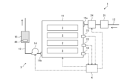
- FIG. 1 is a schematic configuration diagram of a battery pack according to a first embodiment of the present invention
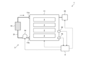
- FIG. 5 is a schematic configuration diagram of a battery pack according to a second embodiment of the present invention.
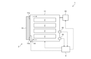
- FIG. 11 is a schematic configuration diagram of a battery pack according to a third embodiment of the present invention.
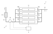
- FIG. 13 is a schematic configuration diagram of a battery pack according to a fourth embodiment of the present invention.
- FIG. 13 is a schematic configuration diagram of a battery pack according to a fifth embodiment of the present invention.
- an all-solid-state battery containing a sulfide-based solid electrolyte is exemplified as a battery cell that can generate an active gas
- hydrogen sulfide which is flammable and corrosive
- the active gas to be removed by the present invention may be other active gases than hydrogen sulfide generated due to an all-solid-state battery containing a sulfide-based solid electrolyte.
- the active gas here means a gas that can chemically react with other elements or compounds.
- active gases examples include sulfur (including allotropes such as S, S 2 , and S 8 ), sulfur oxides (sulfur monoxide, sulfur dioxide, sulfur trioxide, etc.), halogens (fluorine, chlorine, bromine, iodine, etc.), oxygen, and carbon dioxide.
- the active gas may be generated due to other types of batteries, such as hydrogen, carbon dioxide, methane, ethane, ethylene, hydrogen fluoride, and carbon monoxide generated due to lithium ion batteries; fluorine and hydrogen fluoride generated due to fluoride batteries; hydrogen and oxygen generated due to aqueous batteries such as aqueous lithium ion batteries and zinc negative electrode batteries; and sulfur dioxide generated due to inorganic electrolyte batteries.
- the active gas to be removed by the present invention may be a vaporized gas of an organic solvent used in the nonaqueous electrolyte of a lithium ion battery.
- organic solvents include ethylene carbonate, propylene carbonate, fluoroethylene carbonate, dimethyl carbonate, diethyl carbonate, ethyl methyl carbonate, ⁇ -butyrolactone, and propyl propionate.
- FIG. 1 is a schematic diagram of a battery pack according to a first embodiment of the present invention.
- the battery pack 1 has a plurality of battery cells 2 and at least a pair of electrode terminals (not shown).
- the plurality of battery cells 2 are electrically connected to each other.
- the connection form is not particularly limited, and may be in series or parallel, or a combination of these.
- at least a portion of the plurality of battery cells 2 may be restrained by a restraining member.
- At least a pair of electrode terminals are electrically connected to the plurality of battery cells 2 by an electric circuit (not shown) so that power can be taken from the plurality of battery cells 2.
- four battery cells 2 are shown in FIG. 1, the number of battery cells 2 included in the battery pack 1 is not limited to this.
- the battery pack 1 may have a plurality of battery modules (assembled batteries) each including a plurality of battery cells 2.
- the battery cells 2 may be modularized to form a battery module, and a plurality of such battery modules may be combined to form the battery pack 1.
- the battery cell 2 is an all-solid-state battery, and has a positive electrode, a negative electrode, and a solid electrolyte layer disposed between the positive electrode and the negative electrode.
- the positive electrode includes a positive electrode collector and a positive electrode active material layer
- the negative electrode includes a negative electrode collector and a negative electrode active material layer.
- the positive electrode collector, positive electrode active material layer, solid electrolyte layer, negative electrode active material layer, and negative electrode collector are stacked in this order to form a laminate, which is housed in a battery case of a laminate type, a cylindrical type, a square type, or the like.
- a reinforcing layer made of a curable resin may be provided around the laminate, if necessary.
- the positive electrode current collector and the negative electrode current collector may each be a known material commonly used in all-solid-state batteries.
- the positive electrode current collector may be made of a metal material such as aluminum, stainless steel, or titanium, and may take the form of, for example, a foil, film, sheet, or mesh.
- the negative electrode current collector may be made of a metal material such as stainless steel, nickel, or copper, and may take the form of, for example, a foil, film, or sheet.
- the positive electrode active material layer contains at least a positive electrode active material
- the negative electrode active material layer contains at least a negative electrode active material.
- the positive electrode active material is not particularly limited as long as it is a material that absorbs and releases metal ions such as lithium ions, and for example, sulfur, lithium-containing transition metal oxides, transition metal fluorides, polyanion compounds, transition metal sulfides, etc. can be used.
- the negative electrode active material is not particularly limited as long as it is a material that absorbs and releases metal ions such as lithium ions, and for example, metallic lithium, metals or alloys that can be alloyed with lithium, carbon materials such as graphite and hard carbon, transition metal oxides, transition metal sulfides, silicon, etc. can be used.
- the positive electrode active material layer and the negative electrode active material layer may each contain a solid electrolyte, a binder, etc. as appropriate.
- the solid electrolyte layer contains at least a sulfide-based solid electrolyte.
- the sulfide solid electrolyte include glasses or glass ceramics such as Li 2 S-SiS 2 , Li 2 S-B 2 S 3 , Li 2 S-P 2 S 3 , Li 2 S-P 2 S 5 , Li 2 S-GeS 2 , Li 2 S-B 2 S 3 , Li 3 PO 4 -P 2 S 5 , and Li 4 SiO 4 -Li 2 S-SiS 2 , as well as Li 3.25 Ge 0.25 P 0.75 S 4 and Li 10 GeP 2 S 12 .
- the solid electrolyte layer may contain a binder or the like as appropriate, and may contain a solid electrolyte different from the sulfide-based solid electrolyte.
- solid electrolytes include halide-based solid electrolytes, oxide-based solid electrolytes, polymer-based solid electrolytes, hydride-based solid electrolytes, and nitride-based solid electrolytes.
- the battery pack 1 also has a battery housing 3 that houses multiple battery cells 2.
- the battery housing 3 is composed of a housing 11, an intake pipe 12, an exhaust pipe 13, an air blower 14, and a hydrogen sulfide removal section (active gas removal section) 15.
- the housing 11 has a function of housing a plurality of battery cells 2 while drawing out at least a pair of electrode terminals (not shown) to the outside.
- the housing 11 is provided with an intake port 11a for introducing air into the inside of the housing 11 and an exhaust port 11b for discharging air from the inside of the housing 11.
- fillers such as elastic materials, heat transfer materials, and heat insulating materials may be appropriately arranged in gaps between the battery cells 2 or between the battery cells 2 and the above-mentioned restraining members.
- the housing 11 is shown in a simplified manner in FIG.
- the plurality of battery cells 2 are housed in the housing 11 with at least a portion of them in direct or indirect contact with the housing 11 (for example, via the above-mentioned restraining member).
- the shape of the housing 11 is not particularly limited and can be set arbitrarily according to the shape and arrangement of the battery cells 2 to be housed. As described above, the housing 11 may house a plurality of battery modules each including a plurality of battery cells 2.
- One end (downstream end) of the intake pipe 12 is connected to the intake port 11a of the housing 11 via an on-off valve (not shown).
- One end (upstream end) of the exhaust pipe 13 is connected to the exhaust port 11b of the housing 11 via an on-off valve (not shown).
- the connection positions of the intake pipe 12 and the exhaust pipe 13 to the housing 11 are not particularly limited, but are preferably positioned opposite each other to ensure that air circulates evenly inside the housing 11.
- the intake pipe 12 may be provided with a filtering means such as an air filter to prevent foreign matter from entering from the outside.
- the blower 14 is provided in the exhaust pipe 13 and has the function of generating an air flow inside the housing 11.
- the blower 14 there are no particular limitations on the blower 14, and for example, a fan, blower, pump, compressor, etc. can be used.
- the output of the blower 14 is controlled by the control unit 4 described later, and the blower 14 may have the function of adjusting the flow rate of air flowing into the housing 11.
- power may be supplied to the blower 14 from the battery cell 2.
- a separate independent power source may be provided, and this allows the blower 14 to be reliably driven even in a situation where the output of the battery cell 2 must be limited or stopped, as described later.
- the hydrogen sulfide removal unit 15 is provided in the exhaust pipe 13 and has the function of removing hydrogen sulfide (active gas) generated when the sulfide-based solid electrolyte contained in the battery cell 2 reacts with moisture.
- the hydrogen sulfide removal unit 15 is not particularly limited, and for example, a cylindrical container made of a metal such as stainless steel filled with a hydrogen sulfide remover can be used.
- Such removers can be known ones that are generally used to remove hydrogen sulfide, such as ion exchange resins, activated carbon (particularly activated carbon impregnated with a basic compound such as sodium hydroxide or potassium carbonate), activated alumina (particularly activated alumina impregnated with potassium permanganate), zeolite, basic solids such as calcium oxide and calcium carbonate, basic liquids such as aqueous sodium hydroxide and aqueous sodium carbonate, and ionic liquids having a reactive site with acids such as amino groups.
- ion exchange resins activated carbon (particularly activated carbon impregnated with a basic compound such as sodium hydroxide or potassium carbonate), activated alumina (particularly activated alumina impregnated with potassium permanganate), zeolite, basic solids such as calcium oxide and calcium carbonate, basic liquids such as aqueous sodium hydroxide and aqueous sodium carbonate, and ionic liquids having a reactive site with acids such as amino groups.
- Hydrogen sulfide may have a temperature higher than room temperature due to heat generation from the battery cell 2, so it is preferable that the hydrogen sulfide remover maintains its hydrogen sulfide removal performance even at high temperatures, and more preferably, its removal mechanism is based on an irreversible reaction. This allows hydrogen sulfide to be reliably removed even at high temperatures, and also prevents the removed hydrogen sulfide from being released again.
- Some removers may generate powder depending on the environment in which the battery pack 1 is used (for example, when the battery pack 1 is used in an electric vehicle and is subjected to vibration).
- a filtering means such as an air filter may be installed downstream of the hydrogen sulfide removal section 15, which prevents the powder from leaking to the outside and also prevents the powder from blocking the air flow or causing a dust explosion.
- the blower 14 can circulate air from the intake pipe 12 to the exhaust pipe 13 inside the housing 11. Therefore, even if hydrogen sulfide is generated from the battery cell 2, it is possible to prevent the hydrogen sulfide from accumulating inside the housing 11 and increasing the hydrogen sulfide concentration inside the housing 11. As a result, it is possible to reduce the possibility that hydrogen sulfide as a flammable gas reacts with oxygen in the housing 11 and burns, or that hydrogen sulfide as a corrosive gas corrodes the material of the battery cell 2.
- an exhaust pipe separate from the exhaust pipe 13 may be connected to the housing 11 (through an opening and closing valve), so that the exhaust path for hydrogen sulfide can be selected.
- hydrogen sulfide when hydrogen sulfide is discharged to the outside with little impact on the surroundings, hydrogen sulfide can be discharged without passing through the hydrogen sulfide removal unit 15, thereby suppressing deterioration of the hydrogen sulfide removal unit 15.
- the blower 14 is provided in the exhaust pipe 13, the same effect can be obtained if, for example, the exhaust pipe 13 branches into two downstream (via a three-way valve) and the hydrogen sulfide removal unit 15 is provided in one of the two.
- Second Embodiment 2 is a schematic diagram of a battery pack according to a second embodiment of the present invention.
- This embodiment is a modification of the first embodiment, and differs from the first embodiment in that some additional configurations are provided. The following description will focus on the differences from the first embodiment.
- an oxygen remover 21 that removes oxygen from the air flowing into the housing 11 is provided in the intake pipe 12. This allows the oxygen concentration inside the housing 11 to be reduced in addition to the oxygen inside the housing 11 being discharged to the outside by the action of the blower 14.
- the oxygen remover 21 is not particularly limited, and a known oxygen remover that is generally used to remove oxygen can be used. Examples of such removers include metal-based oxygen adsorbents containing iron, copper, nickel, etc., and organic oxygen adsorbents containing vitamin C, etc.
- the oxygen concentration in the housing 11 is monitored, and for that purpose, it is preferable that the battery pack 1 has an oxygen sensor 22 that detects the oxygen concentration in the housing 11.
- the output of the blower 14 may be controlled by the control unit 4 based on the detection result of the oxygen sensor 22. That is, the output of the blower 14 may be controlled to adjust the flow rate of air (specifically, air from which oxygen has been removed) flowing into the housing 11 so that the oxygen concentration detected by the oxygen sensor 22 is less than the limit oxygen concentration of hydrogen sulfide.
- the output of the battery cells 2 may be controlled based on the detection result of the oxygen sensor 22.
- the output of at least some of the battery cells 2 may be limited or stopped for safety.
- the detection result of the oxygen sensor 22 may be stored in the control unit 4 for immediate or future use, or may be transmitted to a server or a blockchain network via the control unit 4.
- the oxygen sensor 22 is not particularly limited, and any known oxygen sensor, such as a zirconia type, an electrochemical type, a magnetic type, an optical type, a laser spectroscopy type, or a yellow phosphorus emission type, can be used. Note that the position of the oxygen sensor 22 is not limited to the position shown in the figure, as long as it can detect the oxygen concentration inside the housing 11, and may be, for example, on the intake pipe 12 (specifically, downstream of the oxygen removal section 21) or on the exhaust pipe 13.
- the battery pack 1 may have a temperature sensor 23 that detects the temperature inside the housing 11, and a temperature adjustment unit 24 that is controlled by the control unit 4 based on the detection result of the temperature sensor 23 and adjusts the temperature of the air flowing into the housing 11.
- the output of at least some of the battery cells 2 may be adjusted based on the detection result of the temperature sensor 23. For example, when the temperature detected by the temperature sensor 23 is outside a predetermined range, the output of at least some of the battery cells 2 may be limited or stopped.
- the temperature sensor 23 is not particularly limited, and for example, a known temperature sensor such as a contact type or a non-contact type can be used. Examples of contact type temperature sensors include a thermocouple, a resistance temperature detector, and a thermistor, and examples of non-contact type temperature sensors include a radiation thermometer.
- the position of the temperature sensor 23 is not limited to the position shown in the figure, as long as it can detect the temperature inside the housing 11. In the example shown in the figure, only one temperature sensor 23 is installed in the housing 11, but multiple temperature sensors 23 may be installed. In that case, a temperature sensor 23 may be installed in the vicinity of each battery cell 2.
- the detection result of the temperature sensor 23 may be stored in the control unit 4 for immediate or future use, or may be transmitted to a server or a blockchain network through the control unit 4.
- the temperature adjustment unit 24 is not particularly limited, and for example, a combination of a known cooling device such as an air-cooled type, a water-cooled type, or a refrigerant type and a known heating device such as an electric heat type or a heat pump type can be used.
- the position of the temperature adjustment unit 24 is not limited to the position shown in the figure, as long as it can adjust the temperature of the battery cell 2.
- the temperature adjustment unit 24 may be provided inside the housing 11 to directly adjust the temperature of the battery cell 2, or may be provided outside the housing 11 to indirectly adjust the temperature of the battery cell 2 via the housing 11.
- the oxygen removal unit 21 and the temperature adjustment unit 24 may be detachable from the housing 11 together with the intake pipe 12.
- the oxygen sensor 22 and the temperature sensor 23 may also be detachable from the housing 11, similar to the hydrogen sulfide sensor 16.
- the hydrogen sulfide removal unit 15 when replacing the hydrogen sulfide removal unit 15, it is preferable that the hydrogen sulfide removal unit 15 is provided with an identifier 25 including its own identification information in order to check whether it is a genuine product, whether the expiration date has not passed, and whether it satisfies the specified conditions of use.
- the identifier 25 may be, for example, an information storage medium such as a wireless tag, or a code such as a one-dimensional code or a two-dimensional code, but is preferably a code, and more preferably a two-dimensional code such as a QR code (registered trademark).
- control unit 4 is provided with a function of communicating with a reading device (not shown) that reads the identification information from the identifier 25 and acquiring the reading result, and it is preferable that the information necessary for identifying the genuine product is recorded.
- a reading device not shown
- the control unit 4 may transmit the acquired identification information of the hydrogen sulfide removal unit 15, the judgment result, the usage status of the hydrogen sulfide removal unit 15, etc.
- the reading result of the identifier 25 by the reading device may be transmitted to a server or a blockchain network instead of to the control unit 4, where the above-mentioned judgment is made, and the judgment result may be transmitted to the control unit 4.
- control unit 4 directly acquires the usage status (usage time, etc.) of all devices that are the communication targets (blower unit 14, sensors 16, 22, 23, etc.), and thereby indirectly acquires the usage status of devices that are not the communication targets (hydrogen sulfide removal unit 15, oxygen removal unit 21, etc.).
- control unit 4 may have a function to predict the life of the hydrogen sulfide removal unit 15 based on the acquired usage status in order to appropriately determine the time (life) when the hydrogen sulfide removal unit 15 needs to be replaced.
- the control unit 4 may have a function to transmit the acquired usage status to a server or a blockchain network in order to enable an external management device to predict the life of the hydrogen sulfide removal unit 15.
- the above-mentioned life prediction enables planned replacement of the hydrogen sulfide removal unit 15, but depending on the usage environment (region) of the battery pack 1 and the manufacturing status of the hydrogen sulfide removal unit 15, new or unused hydrogen sulfide removal units 15 may not be available at the time when the life is predicted to end. In other words, if demand for the hydrogen sulfide removal unit 15 is concentrated in a specific region and a supply shortage occurs as a result, new or unused hydrogen sulfide removal units 15 may not be available in a planned manner. In order to avoid this, it is preferable that the control unit 4 has a function of acquiring location information and a function of transmitting the location information to a server or a blockchain network together with the usage status of each device.
- the external management device may notify the user of the optimal source of acquisition of the hydrogen sulfide removal unit 15. As a result, it becomes possible to obtain the hydrogen sulfide removal unit 15 at the necessary time and place, and planned replacement of the hydrogen sulfide removal unit 15 becomes possible.
- the above description related to the life expectancy prediction of the hydrogen sulfide removal unit 15 applies to all communication target devices whose usage status is directly acquired by the control unit 4, and also to other devices whose usage status is indirectly acquired (such as the oxygen removal unit 21). Incidentally, after replacing those parts including the hydrogen sulfide removal unit 15, it is preferable to collect the replaced parts and analyze their deterioration status, thereby improving the accuracy of the life expectancy prediction of each part. That is, in the case of the hydrogen sulfide removal unit 15 as an example, by collecting and analyzing it, it is possible to grasp the amount of hydrogen sulfide generated during use.
- Third Embodiment 3 is a schematic diagram of a battery pack according to a third embodiment of the present invention.
- This embodiment is a modification of the first embodiment, and differs from the first embodiment in that the configurations of the intake pipe and the exhaust pipe are changed. The following description will focus on the differences from the first embodiment.
- the upstream end (the other end) of the intake pipe 12 and the downstream end (the other end) of the exhaust pipe 13 are both open to the outside, whereas in the present embodiment, they are connected to each other to form a circulation pipe 31 that circulates the air inside the housing 11 without discharging it to the outside.
- This makes it possible to prevent the battery cells 2 from coming into contact with outside air containing moisture, thereby reducing the possibility of generating hydrogen sulfide, compared to the first embodiment.
- the circulation pipe 31 forms a closed circuit, there is almost no possibility of contact between the battery cells 2 and the outside air as described above.
- the internal pressure of the housing 11 may increase or decrease in some cases.
- An increase in internal pressure may occur, for example, when the temperature inside the housing 11 increases due to heat generation from the battery cells 2 or an increase in the outside air temperature, or when gas such as hydrogen sulfide is generated from the battery cells 2.
- a decrease in internal pressure may occur, for example, when the temperature inside the housing 11 decreases due to a decrease in the outside air temperature.
- the battery pack 1 has a pressure sensor 32 that detects the pressure inside the housing 11, and a pressure adjustment unit 33 that is controlled by the control unit 4 based on the detection result of the pressure sensor 32 and adjusts the pressure inside the housing 11. This makes it possible to suppress excessive increase or decrease in the internal pressure of the housing 11.
- the output of at least some of the battery cells 2 may be adjusted based on the detection result of the pressure sensor 32. For example, when the pressure detected by the pressure sensor 32 becomes outside a predetermined range, the output of at least some of the battery cells 2 may be limited or stopped.
- the pressure sensor 32 is not particularly limited, and may be any known pressure sensor, such as a resistive film type, a capacitance type, a piezoelectric element type, a photoelectric type, or a MEMS (MicroElectroMechanical Systems) type.
- the position of the pressure sensor 32 is not limited to the position shown in the figure, as long as it can detect the pressure inside the housing 11.
- the detection results of the pressure sensor 32 may be stored in the control unit 4 for immediate or future use, or may be transmitted to a server or a blockchain network via the control unit 4.
- the pressure adjustment unit 33 is not particularly limited, and may be, for example, an electric valve, a solenoid valve, a relief valve, a compressor, a gas cylinder, an accumulator, or the like.
- the pressure adjustment unit 33 When using a pressure adjustment unit 33 that is an integrated version of the above-mentioned two types, it is preferable that the pressure adjustment unit 33 has a function that allows air to be introduced into and released from the housing 11 so as to eliminate the pressure difference between the inside and outside of the housing 11 while suppressing the intrusion of foreign matter and moisture from the outside. This can also reduce the possibility of the housing 11 being damaged due to the pressure difference between the inside and outside of the housing 11.
- Examples of such pressure adjustment units 33 include an air filter, a moisture removal filter, and a breathable waterproof sheet.
- the position of the pressure adjustment unit 33 is not limited to the position shown in the figure, but in the case of a pressure adjustment unit 33 (including a combination of the two types described above) that has the function of releasing the internal pressure of the housing 11, it is preferable that the pressure adjustment unit 33 is located downstream of the hydrogen sulfide removal unit 15 in the circulation pipe 31.
- the pressure adjustment unit 33 may be provided directly in the container of the hydrogen sulfide removal unit 15, in which case it is preferable that the pressure adjustment unit 33 is provided downstream of the hydrogen sulfide removal agent in the direction of air flow in the container. This can reduce the possibility of hydrogen sulfide leaking to the outside.
- the pressure adjustment unit 33 is provided with a filtering means for removing components (e.g., moisture, oxygen, etc.) other than the non-reactive gas contained in the outside air.
- filtersing means include a moisture removal column, a moisture removal filter, a breathable waterproof sheet, an oxygen removal column, and a nitrogen permeable membrane.
- the number of pressure adjustment units 33 is not limited to one as shown in the figure, and may be multiple.
- the circulation pipe 31 is preferably unitized as a gas flow unit together with the air blower 14 and the hydrogen sulfide removal unit 15. This allows the circulation pipe 31 including the air blower 14 and the hydrogen sulfide removal unit 15 to be treated as a single component when assembling the battery pack 1, thereby reducing the number of components and simplifying the manufacturing process. Furthermore, such gas flow units 14, 15, 31 may be removably attached to the housing 11, similar to the gas flow members 12 to 15 of the first embodiment, and the pressure adjustment unit 33 may also be removably attached to the housing 11. Furthermore, the pressure sensor 32 may also be detachable from the housing 11, similar to the hydrogen sulfide sensor 16.
- each configuration described in the second embodiment can also be applied to this embodiment.
- the oxygen removal unit 21 and the temperature adjustment unit 24 may be provided at a position corresponding to the exhaust pipe 13 (specifically, upstream of the hydrogen sulfide removal unit 15) rather than at a position corresponding to the intake pipe 12 in the circulation pipe 31 (specifically, downstream of the hydrogen sulfide removal unit 15).
- the oxygen removal unit 21 may be structurally and functionally integrated with the hydrogen sulfide removal unit 15, thereby reducing the number of parts and making replacement due to deterioration easier.
- the oxygen removal unit 21 and the hydrogen sulfide removal unit 15 may be arranged in parallel, or in a combination of series and parallel.
- a bypass pipe that bypasses the hydrogen sulfide removal unit 15 may be provided in the circulation pipe 31, and the oxygen removal unit 21 may be provided in the bypass pipe.
- the circulation pipe 31 may be provided with a bypass pipe that bypasses the hydrogen sulfide removal unit 15 and the oxygen removal unit 21 arranged in series, and the hydrogen sulfide removal unit 15 may be provided on the bypass pipe.
- the oxygen removal unit 21 removes oxygen from within the housing 11, the volume of air within the housing 11 may decrease, and as a result, the pressure within the housing 11 may decrease. Therefore, when the oxygen removal unit 21 is applied to this embodiment, it is preferable to use a type of pressure adjustment unit 33 that pressurizes the inside of the housing 11, and thereby the pressure within the housing 11 can be adjusted to an appropriate pressure. That is, for example, the pressure within the housing 11 can be adjusted to an appropriate pressure by compensating for the reduced volume of air using a compressor or a gas cylinder filled with an inert gas.
- (Fourth embodiment) 4 is a schematic diagram of a battery pack according to a fourth embodiment of the present invention.
- This embodiment is a modification of the third embodiment, and differs from the third embodiment in that the circulation piping is omitted.
- the following description will focus on the differences from the third embodiment.
- the circulation piping 31 of the third embodiment is omitted, and accordingly, the blower 14 is provided inside the housing 11, and the hydrogen sulfide removal unit 15 is provided on the housing 11.
- the blower 14 is provided at the exhaust port 11b inside the housing 11, and the hydrogen sulfide removal unit 15 is provided on the housing 11 so that its inlet and outlet are directly connected to the exhaust port 11b and the intake port 11a of the housing 11, respectively.
- the position of the blower 14 is not limited to the inside of the housing 11, and may be on the housing 11. That is, the blower 14 may be attached directly to the exhaust port 11b on the outside of the housing 11. Alternatively, the blower 14 may be attached directly to the intake port 11a on the outside of the housing 11, in which case the outlet of the hydrogen sulfide removal unit 15 and the intake port 11a of the housing 11 may be connected via the blower 14. It goes without saying that the position of the blower 14 within the housing 11 is not particularly limited.
- Fifth Embodiment 5 is a schematic diagram of a battery pack according to a fifth embodiment of the present invention.
- This embodiment is a modification of the first embodiment, and differs from the first embodiment in that the configuration of the casing is changed, and the configurations of the intake pipe and the exhaust pipe are changed accordingly.
- the following description will focus on the differences from the first embodiment.
- the housing 11 has a plurality of storage chambers 41 each housing a battery cell 2. Accordingly, the downstream end of the intake pipe 12 branches into a plurality of parts and is connected to the plurality of storage chambers 41 (specifically, each intake port 41a) via an on-off valve (not shown). The upstream end of the exhaust pipe 13 also branches into a plurality of parts and is connected to the plurality of storage chambers 41 (specifically, each exhaust port 41b) via an on-off valve (not shown). Note that, although four storage chambers 41 are shown in FIG. 4, the number of storage chambers 41 constituting the housing 11 is not limited to this.
Landscapes
- Battery Mounting, Suspending (AREA)
Abstract
Description
図1は、本発明の第1の実施形態に係る電池パックの概略構成図である。
図2は、本発明の第2の実施形態に係る電池パックの概略構成図である。本実施形態は、第1の実施形態の変形例であり、いくつかの付加的な構成が設けられている点で第1の実施形態と異なっている。以下、第1の実施形態との相違点を中心に説明する。
図3は、本発明の第3の実施形態に係る電池パックの概略構成図である。本実施形態は、第1の実施形態の変形例であり、吸気配管と排気配管の構成が変更されている点で第1の実施形態と異なっている。以下、第1の実施形態との相違点を中心に説明する。
図4は、本発明の第4の実施形態に係る電池パックの概略構成図である。本実施形態は、第3の実施形態の変形例であり、循環配管が省略されている点で第3の実施形態と異なっている。以下、第3の実施形態との相違点を中心に説明する。
図5は、本発明の第5の実施形態に係る電池パックの概略構成図である。本実施形態は、第1の実施形態の変形例であり、筐体の構成が変更され、それに伴い吸気配管と排気配管の構成が変更されている点で第1の実施形態と異なっている。以下、第1の実施形態との相違点を中心に説明する。
2 電池セル
3 電池収容体
4 制御部
11 筐体
11a 吸気口
11b 排気口
12 吸気配管
13 排気配管
14 送風部
15 硫化水素除去部(活性ガス除去部)
16 硫化水素センサ(ガスセンサ)
21 酸素除去部
22 酸素センサ
23 温度センサ
24 温度調整部
25 識別子
31 循環配管
32 圧力センサ
33 圧力調整部
41 収容室
41a 吸気口
41b 排気口
Claims (26)
- 吸気口および排気口を有し、少なくとも1つの電池セルを収容する筐体と、
前記筐体の内部に前記吸気口から前記排気口に向かう空気の流れを発生させる送風部と、
前記少なくとも1つの電池セルから発生し、前記空気の流れによって前記排気口から排出される活性ガスを除去する活性ガス除去部と、を有する電池収容体。 - 前記吸気口に一端が接続された吸気配管と、
前記排気口に一端が接続された排気配管と、を有し、
前記送風部は、前記筐体の内部、前記吸気配管、または前記排気配管に設けられ、前記活性ガス除去部は、前記排気配管に設けられている、請求項1に記載の電池収容体。 - 前記吸気配管と、前記吸気配管の他端と他端が接続された前記排気配管とからなり、前記筐体内の空気を循環させる循環配管を有する、請求項2に記載の電池収容体。
- 前記活性ガス除去部は、前記筐体上に設けられ、前記排気口および前記吸気口にそれぞれ直接連通して前記筐体内の空気を循環させる入口および出口を有する、請求項1に記載の電池収容体。
- 前記送風部を制御する制御部を有する、請求項1から4のいずれか1項に記載の電池収容体。
- 前記筐体内の前記活性ガスの存在または濃度を検出するガスセンサを有し、
前記制御部は、前記ガスセンサにより前記活性ガスが検出されたときに、前記送風部を作動させて前記空気の流れを生成する、請求項5に記載の電池収容体。 - 前記筐体内の圧力を検出する圧力センサと、前記圧力センサの検出結果に基づいて前記制御部により制御され、前記筐体内の圧力を調整する圧力調整部と、を有する、請求項5記載の電池収容体。
- 前記活性ガスが可燃性ガスである、請求項1から4のいずれか1項に記載の電池収容体。
- 前記筐体内の前記活性ガスの存在または濃度を検出するガスセンサと、
前記ガスセンサにより検出された前記可燃性ガスの濃度が燃焼下限値未満になるように、前記送風部を制御して前記筐体内に流入する前記空気の流量を調整する制御部と、を有する、請求項8に記載の電池収容体。 - 前記吸気口を通じて前記筐体内に流入する前記空気中の酸素を除去する酸素除去部を有する、請求項8に記載の電池収容体。
- 前記筐体内の酸素濃度を検出する酸素センサと、
前記酸素センサにより検出された前記酸素濃度が前記可燃性ガスの限界酸素濃度未満になるように、前記送風部を制御して前記筐体内に流入する前記空気の流量を調整する制御部と、を有する、請求項10に記載の電池収容体。 - 前記活性ガス除去部には、前記活性ガス除去部の識別情報を含む識別子が付与され、
前記制御部は、前記識別子から読み取られた前記識別情報に基づいて、前記活性ガス除去部が所定の条件を満たすものであるか否かを判定する、請求項5に記載の電池収容体。 - 前記筐体内の温度を検出する温度センサと、前記温度センサの検出結果に基づいて前記制御部により制御され、前記筐体内の温度を調整する温度調整部と、を有する、請求項5に記載の電池収容体。
- 前記制御部は、少なくとも前記送風部の使用状況に基づいて、前記活性ガス除去部の寿命を予測する、請求項5に記載の電池収容体。
- 前記制御部は、位置情報を取得し、該取得した位置情報と少なくとも前記送風部の使用状況とを外部に送信する、請求項5に記載の電池収容体。
- 前記吸気配管と前記排気配管と前記送風部と前記活性ガス除去部とは、前記筐体に着脱可能に取り付けられている、請求項2または3に記載の電池収容体。
- 前記筐体は、それぞれが電池セルを収容する複数の収容室を備え、
前記吸気配管と前記排気配管の前記一端は、それぞれが複数に分岐して前記複数の収容室に接続されている、請求項2または3に記載の電池収容体。 - 前記複数の収容室内の前記活性ガスの存在を検出する少なくとも1つのガスセンサと、
前記少なくとも1つのガスセンサの検出結果に基づいて、前記複数の収容室のいずれの収容室に前記空気の流れを発生させるかを切り替える制御部と、を有する、請求項17に記載の電池収容体。 - 少なくとも1つの電池セルと、
請求項1から4のいずれか1項に記載の電池収容体と、
前記少なくとも1つの電池セルを制御する制御部と、を有する電池パック。 - 前記電池収容体が、前記筐体内の前記活性ガスの存在を検出するガスセンサを有し、
前記制御部は、前記ガスセンサにより前記活性ガスが検出されたときに、前記少なくとも1つの電池セルの出力を制限または停止する、請求項19に記載の電池パック。 - 前記電池収容体が、前記筐体内の温度を検出する温度センサと、前記筐体内の酸素濃度を検出する酸素センサとの少なくとも一方を有し、
前記制御部は、前記温度センサと前記酸素センサとの少なくとも一方の検出結果に基づいて、前記少なくとも1つの電池セルの出力を調整する、請求項19に記載の電池パック。 - 前記活性ガス除去部には、前記活性ガス除去部の識別情報を含む識別子が付与され、
前記制御部は、前記識別子から読み取られた前記識別情報に基づいて、前記活性ガス除去部が所定の条件を満たすものであるか否かを判定し、前記所定の条件を満たすものでないと判定した場合に前記少なくとも1つの電池セルの出力を行わない、請求項19に記載の電池パック。 - 前記電池収容体が、前記吸気口に一端が接続された吸気配管と、前記排気口に一端が接続され、前記吸気配管の他端に他端が接続された排気配管とからなり、前記筐体内の空気を循環させる循環配管と、前記筐体内の圧力を検出する圧力センサとを有し、
前記制御部は、前記圧力センサの検出結果に基づいて、前記少なくとも1つの電池の出力を調整する、請求項19に記載の電池パック。 - 複数の電池セルと、
請求項17に記載の電池収容体と、
前記複数の電池セルを制御する制御部と、を有する電池パック。 - 前記電池収容体が、前記複数の収容室内の前記活性ガスの存在を検出する少なくとも1つのガスセンサを有し、
前記制御部は、前記少なくとも1つのガスセンサの検出結果に基づいて、前記複数の電池セルのいずれの電池セルの出力を制限または停止するかを切り替える、請求項24に記載の電池パック。 - 少なくとも1つの電池セルを収容する筐体の内部に気体を流通させる気体流通ユニットであって、
両端が前記筐体に接続され、前記筐体内の空気を循環させる循環配管と、
前記循環配管に設けられ、前記筐体内に空気の流れを発生させる送風部と、
前記循環配管に設けられ、前記少なくとも1つの電池セルから発生して前記循環配管を流通する活性ガスを除去する活性ガス除去部と、を有する気体流通ユニット。
Priority Applications (2)
| Application Number | Priority Date | Filing Date | Title |
|---|---|---|---|
| CN202480043786.7A CN121444272A (zh) | 2023-06-29 | 2024-06-19 | 电池收容体和电池组 |
| JP2025529689A JPWO2025004937A1 (ja) | 2023-06-29 | 2024-06-19 |
Applications Claiming Priority (2)
| Application Number | Priority Date | Filing Date | Title |
|---|---|---|---|
| JP2023-106597 | 2023-06-29 | ||
| JP2023106597 | 2023-06-29 |
Publications (1)
| Publication Number | Publication Date |
|---|---|
| WO2025004937A1 true WO2025004937A1 (ja) | 2025-01-02 |
Family
ID=93938385
Family Applications (1)
| Application Number | Title | Priority Date | Filing Date |
|---|---|---|---|
| PCT/JP2024/022252 Ceased WO2025004937A1 (ja) | 2023-06-29 | 2024-06-19 | 電池収容体および電池パック |
Country Status (3)
| Country | Link |
|---|---|
| JP (1) | JPWO2025004937A1 (ja) |
| CN (1) | CN121444272A (ja) |
| WO (1) | WO2025004937A1 (ja) |
Cited By (1)
| Publication number | Priority date | Publication date | Assignee | Title |
|---|---|---|---|---|
| CN121076381A (zh) * | 2025-11-10 | 2025-12-05 | 重庆长安汽车股份有限公司 | 电池包、车辆和电池包的控制方法 |
Citations (10)
| Publication number | Priority date | Publication date | Assignee | Title |
|---|---|---|---|---|
| JPH07237907A (ja) * | 1994-02-22 | 1995-09-12 | Kaoru Asada | 不燃性ガス製造方法及び不燃性ガス製造組成物並びに不燃性ガス製造装置及び消火装置 |
| JP2005223087A (ja) * | 2004-02-04 | 2005-08-18 | Hitachi Plant Eng & Constr Co Ltd | ドラフトチャンバ |
| JP2006228610A (ja) * | 2005-02-18 | 2006-08-31 | Densei Lambda Kk | 二次電池パック |
| JP2015041598A (ja) * | 2013-08-23 | 2015-03-02 | トヨタ自動車株式会社 | 硫化物系固体電解質を含む電池の破損を検出する装置及び方法 |
| WO2015029567A1 (ja) * | 2013-08-26 | 2015-03-05 | 日本碍子株式会社 | 排気処理装置及び収容装置 |
| JP2016192261A (ja) * | 2015-03-30 | 2016-11-10 | 三菱重工業株式会社 | 蓄電システム、制御装置、二次電池の消火方法およびプログラム |
| JP2018073802A (ja) | 2016-04-25 | 2018-05-10 | パナソニックIpマネジメント株式会社 | 電池、および、電池システム |
| JP2020068097A (ja) * | 2018-10-24 | 2020-04-30 | ロベルト・ボッシュ・ゲゼルシャフト・ミト・ベシュレンクテル・ハフツングRobert Bosch Gmbh | ガス監視システム |
| US20200152930A1 (en) * | 2018-11-13 | 2020-05-14 | International Business Machines Corporation | Pressure-induced battery pack venting with filtering |
| WO2020116089A1 (ja) * | 2018-12-04 | 2020-06-11 | パナソニックIpマネジメント株式会社 | 電池パック、電源システム |
-
2024
- 2024-06-19 JP JP2025529689A patent/JPWO2025004937A1/ja active Pending
- 2024-06-19 WO PCT/JP2024/022252 patent/WO2025004937A1/ja not_active Ceased
- 2024-06-19 CN CN202480043786.7A patent/CN121444272A/zh active Pending
Patent Citations (10)
| Publication number | Priority date | Publication date | Assignee | Title |
|---|---|---|---|---|
| JPH07237907A (ja) * | 1994-02-22 | 1995-09-12 | Kaoru Asada | 不燃性ガス製造方法及び不燃性ガス製造組成物並びに不燃性ガス製造装置及び消火装置 |
| JP2005223087A (ja) * | 2004-02-04 | 2005-08-18 | Hitachi Plant Eng & Constr Co Ltd | ドラフトチャンバ |
| JP2006228610A (ja) * | 2005-02-18 | 2006-08-31 | Densei Lambda Kk | 二次電池パック |
| JP2015041598A (ja) * | 2013-08-23 | 2015-03-02 | トヨタ自動車株式会社 | 硫化物系固体電解質を含む電池の破損を検出する装置及び方法 |
| WO2015029567A1 (ja) * | 2013-08-26 | 2015-03-05 | 日本碍子株式会社 | 排気処理装置及び収容装置 |
| JP2016192261A (ja) * | 2015-03-30 | 2016-11-10 | 三菱重工業株式会社 | 蓄電システム、制御装置、二次電池の消火方法およびプログラム |
| JP2018073802A (ja) | 2016-04-25 | 2018-05-10 | パナソニックIpマネジメント株式会社 | 電池、および、電池システム |
| JP2020068097A (ja) * | 2018-10-24 | 2020-04-30 | ロベルト・ボッシュ・ゲゼルシャフト・ミト・ベシュレンクテル・ハフツングRobert Bosch Gmbh | ガス監視システム |
| US20200152930A1 (en) * | 2018-11-13 | 2020-05-14 | International Business Machines Corporation | Pressure-induced battery pack venting with filtering |
| WO2020116089A1 (ja) * | 2018-12-04 | 2020-06-11 | パナソニックIpマネジメント株式会社 | 電池パック、電源システム |
Cited By (2)
| Publication number | Priority date | Publication date | Assignee | Title |
|---|---|---|---|---|
| CN121076381A (zh) * | 2025-11-10 | 2025-12-05 | 重庆长安汽车股份有限公司 | 电池包、车辆和电池包的控制方法 |
| CN121076381B (zh) * | 2025-11-10 | 2026-02-03 | 重庆长安汽车股份有限公司 | 电池包、车辆和电池包的控制方法 |
Also Published As
| Publication number | Publication date |
|---|---|
| CN121444272A (zh) | 2026-01-30 |
| JPWO2025004937A1 (ja) | 2025-01-02 |
Similar Documents
| Publication | Publication Date | Title |
|---|---|---|
| KR102942238B1 (ko) | 소화장치를 포함하는 배터리 팩 | |
| JP7506157B2 (ja) | 熱暴走検出方法及び電池管理システム | |
| ES2450122T3 (es) | Acumulador eléctrico de energía | |
| CN102484295B (zh) | 硫化物系全固体锂二次电池系统 | |
| JP5796160B2 (ja) | 蓄電システム | |
| US20130252043A1 (en) | System and Method for Controlling Humidity in a Battery Module | |
| JP2017147128A (ja) | 電池モジュール、および、電池システム | |
| WO2025004937A1 (ja) | 電池収容体および電池パック | |
| EP3352273B1 (en) | Fuel cell and control method, | |
| WO2025004936A1 (ja) | 電池収容体および電池パック | |
| CN119113452A (zh) | 热失控管理方法、热失控管理系统及电池包 | |
| KR20140085764A (ko) | 나트륨 유황 전지 및 나트륨 유황 전지 모듈 | |
| JP2009087825A (ja) | 燃料電池システム | |
| JP2025165067A (ja) | 電池収容体、電池モジュール、および電池パック | |
| CN215834593U (zh) | 一种锂离子电池智能冷却降温系统 | |
| CN216648553U (zh) | 一种电池和用电设备 | |
| US20150188178A1 (en) | Safety System for a Flow Battery and Flow Battery System | |
| US20250149665A1 (en) | Battery pack and method for removing hydrogen sulfide in battery pack | |
| JP2012133890A (ja) | 二次電池の防錆システム | |
| CN119153882A (zh) | 压力调节方法、压力调节系统及热失控管理系统 | |
| CN223451105U (zh) | 压力调节系统、热失控管理系统及电池包 | |
| CN223366132U (zh) | 热失控管理系统及电池包 | |
| KR102841534B1 (ko) | 배터리모듈 냉각 기능을 갖는 에너지 저장 시스템 | |
| WO1998032186A1 (fr) | Module de piles sodium-soufre | |
| US20260031411A1 (en) | Battery monitoring system |
Legal Events
| Date | Code | Title | Description |
|---|---|---|---|
| 121 | Ep: the epo has been informed by wipo that ep was designated in this application |
Ref document number: 24831799 Country of ref document: EP Kind code of ref document: A1 |
|
| ENP | Entry into the national phase |
Ref document number: 2025529689 Country of ref document: JP Kind code of ref document: A |
|
| WWE | Wipo information: entry into national phase |
Ref document number: 2025529689 Country of ref document: JP |
|
| WWE | Wipo information: entry into national phase |
Ref document number: 2024831799 Country of ref document: EP |
|
| NENP | Non-entry into the national phase |
Ref country code: DE |
|
| ENP | Entry into the national phase |
Ref document number: 2024831799 Country of ref document: EP Effective date: 20260129 |
|
| ENP | Entry into the national phase |
Ref document number: 2024831799 Country of ref document: EP Effective date: 20260129 |