WO2025004882A1 - コイルばねおよびコイルばねの製造方法 - Google Patents
コイルばねおよびコイルばねの製造方法 Download PDFInfo
- Publication number
- WO2025004882A1 WO2025004882A1 PCT/JP2024/021863 JP2024021863W WO2025004882A1 WO 2025004882 A1 WO2025004882 A1 WO 2025004882A1 JP 2024021863 W JP2024021863 W JP 2024021863W WO 2025004882 A1 WO2025004882 A1 WO 2025004882A1
- Authority
- WO
- WIPO (PCT)
- Prior art keywords
- coil spring
- wire
- coating layer
- coating
- manufacturing
- Prior art date
- Legal status (The legal status is an assumption and is not a legal conclusion. Google has not performed a legal analysis and makes no representation as to the accuracy of the status listed.)
- Ceased
Links
Images


Classifications
-
- F—MECHANICAL ENGINEERING; LIGHTING; HEATING; WEAPONS; BLASTING
- F16—ENGINEERING ELEMENTS AND UNITS; GENERAL MEASURES FOR PRODUCING AND MAINTAINING EFFECTIVE FUNCTIONING OF MACHINES OR INSTALLATIONS; THERMAL INSULATION IN GENERAL
- F16F—SPRINGS; SHOCK-ABSORBERS; MEANS FOR DAMPING VIBRATION
- F16F1/00—Springs
- F16F1/02—Springs made of steel or other material having low internal friction; Wound, torsion, leaf, cup, ring or the like springs, the material of the spring not being relevant
-
- F—MECHANICAL ENGINEERING; LIGHTING; HEATING; WEAPONS; BLASTING
- F16—ENGINEERING ELEMENTS AND UNITS; GENERAL MEASURES FOR PRODUCING AND MAINTAINING EFFECTIVE FUNCTIONING OF MACHINES OR INSTALLATIONS; THERMAL INSULATION IN GENERAL
- F16F—SPRINGS; SHOCK-ABSORBERS; MEANS FOR DAMPING VIBRATION
- F16F1/00—Springs
- F16F1/02—Springs made of steel or other material having low internal friction; Wound, torsion, leaf, cup, ring or the like springs, the material of the spring not being relevant
- F16F1/04—Wound springs
- F16F1/06—Wound springs with turns lying in cylindrical surfaces
-
- F—MECHANICAL ENGINEERING; LIGHTING; HEATING; WEAPONS; BLASTING
- F16—ENGINEERING ELEMENTS AND UNITS; GENERAL MEASURES FOR PRODUCING AND MAINTAINING EFFECTIVE FUNCTIONING OF MACHINES OR INSTALLATIONS; THERMAL INSULATION IN GENERAL
- F16F—SPRINGS; SHOCK-ABSORBERS; MEANS FOR DAMPING VIBRATION
- F16F1/00—Springs
- F16F1/02—Springs made of steel or other material having low internal friction; Wound, torsion, leaf, cup, ring or the like springs, the material of the spring not being relevant
- F16F1/04—Wound springs
- F16F1/12—Attachments or mountings
Definitions
- the present invention relates to a coil spring and a method for manufacturing a coil spring.
- Coil springs have been used as spring components in vehicle suspension systems and the like.
- Coil springs are generally formed by winding a wire rod with a circular cross section (see, for example, Patent Document 1).
- these coil springs are provided with a covering tube to suppress abnormal noises that occur when the wire rods come into contact with each other (inter-wire contact) when compressed by vibration, impact, etc.
- coil springs are also required to be resistant to wear caused by such contact.
- the present invention has been made in consideration of the above, and aims to provide a coil spring and a method for manufacturing a coil spring that can ensure wear resistance even when there are narrow gaps between the wires.
- the coil spring of the present invention is a coil spring formed by winding a wire in a spiral shape, and is characterized in that a coating layer is provided on at least a portion of the surface of the wire in the portion where the gap between the wires is narrower than the wire diameter of the wire, and the coating layer contains a slip agent.
- the coil spring according to the present invention is characterized in that, in the above invention, the wire is coated with a coating film, and the coating layer is provided on the coating film.
- the coil spring according to the present invention is characterized in that the coating layer contains a rust inhibitor.
- the method for manufacturing a coil spring according to the present invention is a method for manufacturing a coil spring by spirally winding a wire, and is characterized in that a coating layer is formed by applying a coating agent containing a slip agent to at least a portion of the surface of the wire in the portion where the gap between the wires is narrower than the wire diameter of the wire.
- the method for manufacturing a coil spring according to the present invention is characterized in that, in the above invention, the coating layer is formed by immersing the wire in the liquid coating agent.
- the method for manufacturing a coil spring according to the present invention is characterized in that, in the above invention, the coating layer is formed by spraying the coating agent onto the wire.
- the method for manufacturing a coil spring according to the present invention is characterized in that, in the above invention, the wire is coated with a coating film, and the coating layer is formed on the coating film.
- the method for manufacturing a coil spring according to the present invention is characterized in that in the above invention, the coating film is subjected to a surface treatment, and the coating layer is formed on the coating film that has been subjected to the surface treatment.
- the present invention has the effect of ensuring wear resistance even when there are narrow gaps between wires.
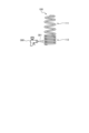
- FIG. 1 is a plan view showing the configuration of a coil spring according to an embodiment of the present invention.
- FIG. 2 is a diagram (part 1) for explaining an example of a method for forming a coating layer in a coil spring according to an embodiment of the present invention.
- FIG. 3 is a diagram (part 2) for explaining an example of a method for forming a coating layer in a coil spring according to an embodiment of the present invention.
- FIG. 1 is a plan view showing the configuration of a coil spring according to an embodiment of the present invention.
- the coil spring 1 is formed by, for example, winding a wire made of spring steel in a spiral shape around a predetermined axis. In this embodiment, an example will be described in which the predetermined axis coincides with the central axis N of the coil spring 1.
- the coil spring 1 is used, for example, as a suspension spring, an engine valve spring, a drive system component (clutch) spring, a tensioner spring, etc.
- the coil spring 1 is formed by winding a wire in a spiral shape around a central axis N.
- the wire is formed using, for example, spring steel or other metal materials. Examples of other metal materials include materials made of a single metal and materials made of an alloy.
- a wire formed using a resin or the like may be used.
- FIG. 1 a configuration is shown in which the diameter (the diameter of the circle formed by the wire when viewed from the direction of the central axis N) due to the winding (winding) is partially different in the direction of the central axis N, but this is not limited to this, and the diameter can be appropriately changed in design.
- FIG. 1 a configuration is shown in which the diameter (the diameter of the circle formed by the wire when viewed from the direction of the central axis N) due to the winding (winding) is partially different in the direction of the central axis N, but this is not limited to this, and the diameter can be appropriately changed in design.
- FIG. 1 a configuration is shown in which the diameter (
- the coil spring may also be, for example, a coil spring in which a wire is wound around a center line that is at least partially curved.
- the coil spring 1 has a pitch that is different in parts along the central axis N, which corresponds to the distance between the central axes of the wire rods. Therefore, in the coil spring 1, the gap between the wire rods is different in parts along the central axis N.
- the gap between the wire rods corresponds to the distance between the wire rods in the central axis N direction (gap distance Is (see Figure 1)), and for example, in the example shown in Figure 1, the gap on the right side of Figure 1 is smaller than the gap on the left side.
- the coil spring 1 has a first winding portion 11 and a second winding portion 12 that is continuous with the first winding portion 11.
- the gap distance of the second winding portion 12 is relatively narrower than the gap distance of the first winding portion 11.
- the gap distance Is of the second winding portion 12 is smaller than the wire diameter Rr of the wire constituting the coil spring 1.
- the wire diameter Rr corresponds to the diameter of the wire cross section when the wire cross section is circular in a cross section cut on a plane perpendicular to the longitudinal direction of the wire.
- the wire diameter corresponds to, for example, the length of one side forming the outer edge or the length of the diagonal in the cross section cut on a plane perpendicular to the longitudinal direction of the wire.
- the length of the cross section of this angular wire corresponds to the "wire diameter".
- the gap distance of the first winding portion 11 is described as being larger than the wire diameter Rr even at its narrowest gap.
- a coating layer 12a is provided on the second winding portion 12. This coating layer 12a is formed on the outermost surface of the coil spring 1.
- the coating layer 12a is, for example, a film formed by a coating agent in which a polymeric material or an inorganic material is mixed with a slip agent, that is, a polymeric film containing a slip agent, or an inorganic film containing a slip agent.
- the polymer material can be selected from thermoplastic resins, thermoplastic elastomers, thermosetting resins, thermosetting elastomers, etc.
- Thermoplastic resins include various resins such as polyolefin resin, polyvinyl chloride resin, polyvinylidene chloride resin, polystyrene resin, polyester resin, polyamide resin, polycarbonate resin, polyvinyl acetate resin, polyurethane resin, polytetrafluoroethylene resin, and polyacrylic resin.
- Thermoplastic elastomers include various elastomers such as styrene-based thermoplastic elastomers, olefin-based thermoplastic elastomers, vinyl chloride-based thermoplastic elastomers, urethane-based thermoplastic elastomers, and amide-based thermoplastic elastomers.
- Thermosetting resins include various resins such as phenolic resins, epoxy resins, melamine resins, urea resins, unsaturated polyester resins, alkyd resins, polyurethanes, and thermosetting polyimides.
- Thermosetting elastomers include various resins such as isoprene rubber, butadiene rubber, styrene-butadiene rubber, acrylonitrile-butadiene rubber, chloroprene rubber, nitrile rubber, butyl rubber, ethylene propylene rubber, chlorosulfonated polyethylene, acrylic rubber, fluororubber, epichlorohydrin rubber, urethane rubber, and silicone rubber.
- Ceramics include oxides such as aluminum oxide, magnesium oxide, zinc oxide, titanium oxide, and silicon oxide, nitrides such as boron nitride, aluminum nitride, and silicon nitride, carbides such as silicon carbide and boron carbide, and composites of these.
- Slip agents include, for example, hydrocarbon compounds, oxyfatty acids or their metal salts, fatty alcohols, silicone compounds, and fluorine compounds.
- hydrocarbon compounds examples include low molecular weight waxes, paraffin waxes, polyethylene waxes, and chlorinated hydrocarbons.
- oxyfatty acids or metal salts thereof include higher fatty acids such as lauric acid, stearic acid, and behenic acid, hydroxystearic acid, and metal salts thereof (metal salts such as zinc), etc.
- fatty alcohols examples include stearyl alcohol, lauryl alcohol, palmityl alcohol, etc.
- silicone compounds examples include polydimethylsiloxane, polyether-modified polydimethylsiloxane, polymethylalkylsiloxane, etc.
- fluorine-based compounds include polytetrafluoroethylene (PTFE); tetrafluoroethylene-perfluoromethyl vinyl ether copolymer (MFA), tetrafluoroethylene-perfluoroethyl vinyl ether copolymer (EFA), tetrafluoroethylene-perfluoropropyl vinyl ether copolymer, and other tetrafluoroethylene-perfluoroalkyl vinyl ether copolymers (PFAs).
- PTFE polytetrafluoroethylene
- MFA tetrafluoroethylene-perfluoromethyl vinyl ether copolymer
- EDA tetrafluoroethylene-perfluoroethyl vinyl ether copolymer
- PFAs tetrafluoroethylene-perfluoropropyl vinyl ether copolymer
- Slip agents also include inorganic fillers (calcium carbonate, talc, kaolin clay, silica, mica, calcium silicate, aluminum hydroxide, alumina, barium sulfate, titanium dioxide, zinc oxide, etc.).
- inorganic fillers calcium carbonate, talc, kaolin clay, silica, mica, calcium silicate, aluminum hydroxide, alumina, barium sulfate, titanium dioxide, zinc oxide, etc.
- a rust inhibitor or a material having wear resistance may be added to the slip agent.
- the rust inhibitor include amine-based organic compounds, condensed aluminum phosphate, and fatty acid salts.
- examples of the amine-based organic compounds include nitrites, carbonates, and carboxylates of amines.
- materials that function as lubricants or surfactants can also be used as the slip agent.
- the slip agent may be contained in the polymeric material film or inorganic film in a molecular dispersed state or in a particulate form.
- a method for forming the coating layer 12a in the second winding portion 12 will be described with reference to Figures 2 and 3.
- Examples of methods for forming the coating layer 12a include application methods such as dipping and spraying. Below, the dipping and spraying methods will be described, but other known methods such as application with a brush or nozzle can also be used.
- FIG. 2 is a diagram for explaining an example of a method for forming a coating layer in a coil spring according to an embodiment of the present invention.
- the immersion method as shown in Fig. 2, in a coil spring 100 having a first winding portion 111 whose winding pattern of the wire corresponds to the first winding portion 11 and a second winding portion 112 whose winding pattern of the wire corresponds to the second winding portion 12, the second winding portion 112 is placed in a container 200 containing the above-mentioned coating agent 201 and is held for a predetermined time or held in the liquid while being rocked.
- the coating agent adheres to the surface of the second winding portion 112, and the coating layer 12a is formed by drying and solidifying it.
- FIG. 3 is a diagram for explaining an example of a method for forming a coating layer in a coil spring according to an embodiment of the present invention.
- a spray 300 is used to spray the above-mentioned coating agent 301 in a mist form onto the second winding portion 112, and the sprayed coating agent is sprayed onto the second winding portion 112.
- the spray causes the coating agent to adhere to the surface of the second winding portion 112, and the coating layer 12a is formed by drying and solidifying the coating agent.
- a coating layer 12a is formed in the portion where the gap distance is narrower than the wire diameter (wire diameter Rr), thereby suppressing wear when the wires come into contact with each other. According to this embodiment, by forming this coating layer 12a, wear resistance can be ensured even in the coil spring where the gap between the wires is narrow in some portions.
- a coating is applied to the surface of the wire that constitutes the coil spring 1. This coating is applied to improve the corrosion resistance of the wire, and covers the entire wire.
- Coating materials include known corrosion-resistant materials such as polyurethane resin and acrylic resin. The coating is applied by a known coating method such as powder coating.
- the coil spring 1 is produced by forming a coating layer 12a on the second winding portion 112 of the coil spring 100 (see FIG. 2, for example) to which the above-mentioned coating film has been applied. That is, the coating layer 12a is provided on the coating film.
- the second winding portion 112 it is preferable to subject the second winding portion 112 to a surface treatment before forming the coating layer 12a.
- a surface treatment known treatments such as plasma treatment, blast treatment, primer treatment, corona treatment, and flame treatment can be used.
- a surface treatment is performed on the second winding portion 112 of the coil spring 100.
- a plasma treatment is performed to form minute irregularities on the surface (coating surface) of the second winding portion 112, which can increase the adhesive strength of the coating layer 12a.
- a coating layer 12a is formed in the portion where the gap distance is narrower than the wire diameter (wire diameter Rr) to suppress wear when the wires come into contact with each other. According to this modified example, the formation of this coating layer 12a ensures wear resistance even when the coil spring has a portion where the gap between the wires is narrow.
- coating layer 12a to coil spring 100 in which a coating film is applied to the wire, it is possible to provide wear resistance while ensuring the corrosion resistance of the wire. Furthermore, according to this modified example, by performing a surface treatment on the coating film, it is possible to further strengthen the adhesion of coating layer 12a to the wire (coating film).
- the present invention should not be limited to only the above-mentioned embodiment.
- the coating layer 12a is applied at least to positions where the wires can come into contact with each other due to deformation of the coil spring 1.
- the coating layer 12a may be formed on the portion of the second winding portion 12 where the wires face each other in the direction of the central axis N.
- the coating layer is also formed intermittently to match the gaps.
- the present invention may include various embodiments not described here, and various design changes may be made without departing from the technical ideas defined by the claims.
- the coating layer of the present invention can also be applied to, for example, stacked leaf springs formed by stacking multiple leaf springs.
- stacked leaf springs when a load is applied from the stacking direction (thickness direction of the leaf springs), the leaf springs are deflected and deformed, which may cause the end regions of the leaf springs to come into contact with each other, resulting in the generation of abnormal noise.
- a sound-absorbing member called a silencer may be provided in advance at the end region of the leaf spring.
- the coating layer of the present invention can be provided at least in part of the end regions where the leaf springs may come into contact when activated, thereby improving wear resistance. By doing so, the durability of the stacked leaf springs can be improved.
- the coil spring and the manufacturing method of the coil spring according to the present invention are suitable for ensuring wear resistance even when there are narrow gaps between the wires.
Landscapes
- Engineering & Computer Science (AREA)
- General Engineering & Computer Science (AREA)
- Mechanical Engineering (AREA)
- Springs (AREA)
Abstract
本発明に係るコイルばねは、線材を螺旋状に巻回してなるコイルばねであって、線材間の隙間が、当該線材の線径よりも狭い部分において、該線材の表面の少なくとも一部にコーティング層が設けられ、コーティング層は、スリップ剤を含む。
Description
本発明は、コイルばねおよびコイルばねの製造方法に関するものである。
従来、車両の懸架装置等に用いられるばね部材として、コイルばねが用いられている。コイルばねは、一般に、断面が円をなす線材を巻回することによって形成される(例えば、特許文献1を参照)。また、このコイルばねには、振動や衝撃等によって圧縮した際に、線材同士が接触(線間接触)することで発生する異音を抑制するために、被覆チューブが設けられる。
ところで、コイルばねには、線間接触による異音防止のほか、該接触による摩耗等に対する耐摩耗性が求められる。
しかしながら、線材間の隙間が狭いと、被覆チューブを被覆することが困難となり、当該被覆チューブが非配設のコイルばねとなる。被覆チューブが非配設のコイルばねでは、線間接触等による耐摩耗性が低下するおそれがあった。
本発明は、上記に鑑みてなされたものであって、線材間の隙間が狭い部分を有する場合であっても耐摩耗性を確保することができるコイルばねおよびコイルばねの製造方法を提供することを目的とする。
上述した課題を解決し、目的を達成するために、本発明に係るコイルばねは、線材を螺旋状に巻回してなるコイルばねであって、前記線材間の隙間が、当該線材の線径よりも狭い部分において、該線材の表面の少なくとも一部にコーティング層が設けられ、前記コーティング層は、スリップ剤を含む、ことを特徴とする。
また、本発明に係るコイルばねは、上記発明において、前記線材には、塗膜が施され、前記コーティング層は、前記塗膜上に設けられる、ことを特徴とする。
また、本発明に係るコイルばねは、上記発明において、前記コーティング層は、防錆剤を含む、ことを特徴とする。
また、本発明に係るコイルばねの製造方法は、線材を螺旋状に巻回してなるコイルばねの製造方法であって、前記線材間の隙間が、当該線材の線径よりも狭い部分において、該線材の表面の少なくとも一部に、スリップ剤を含む塗布剤を塗布することによってコーティング層を形成する、ことを特徴とする。
また、本発明に係るコイルばねの製造方法は、上記発明において、液状の前記塗布剤中に前記線材を浸漬させることによって、前記コーティング層を形成する、ことを特徴とする。
また、本発明に係るコイルばねの製造方法は、上記発明において、前記線材に対して前記塗布剤を噴霧することによって、前記コーティング層を形成する、ことを特徴とする。
また、本発明に係るコイルばねの製造方法は、上記発明において、前記線材には、塗膜が施されており、前記塗膜上に前記コーティング層を形成する、ことを特徴とする。
また、本発明に係るコイルばねの製造方法は、上記発明において、前記塗膜に表面処理を施し、該表面処理が施された前記塗膜上に前記コーティング層を形成する、ことを特徴とする。
本発明によれば、線材間の隙間が狭い部分を有する場合であっても耐摩耗性を確保することができるという効果を奏する。
以下、添付図面を参照して本発明を実施するための形態(以下、「実施の形態」という)を説明する。なお、図面は模式的なものであって、各部分の厚みと幅との関係、それぞれの部分の厚みの比率などは現実のものとは異なる場合があり、図面の相互間においても互いの寸法の関係や比率が異なる部分が含まれる場合がある。
(実施の形態)
図1は、本発明の一実施の形態に係るコイルばねの構成を示す平面図である。
コイルばね1は、例えば、ばね鋼からなる線材を、所定の軸に対して螺旋状に巻回してなる。本実施の形態では、この所定の軸が、コイルばね1の中心軸Nと一致する例について説明する。コイルばね1は、例えば、懸架用ばね、エンジンバルブ用ばね、駆動系部品(クラッチ)用ばね、テンショナ用ばね等として用いられる。
図1は、本発明の一実施の形態に係るコイルばねの構成を示す平面図である。
コイルばね1は、例えば、ばね鋼からなる線材を、所定の軸に対して螺旋状に巻回してなる。本実施の形態では、この所定の軸が、コイルばね1の中心軸Nと一致する例について説明する。コイルばね1は、例えば、懸架用ばね、エンジンバルブ用ばね、駆動系部品(クラッチ)用ばね、テンショナ用ばね等として用いられる。
コイルばね1は、線材を中心軸Nのまわりに螺旋状に旋回させてなる。線材は、例えば、ばね用鋼やその他金属等の材料を用いて形成される。その他金属等の材料は、単体の金属からなる材料や、合金からなる材料が挙げられる。このほか、樹脂等を用いて形成される線材を用いてもよい。
なお、図1に示す例では、中心軸N方向において、旋回(巻回)による径(中心軸N方向からみたときに線材のなす円の径)が、部分的に異なる構成を示しているが、これに限らず、その径は適宜設計の変更が可能である。
また、図1では、直線に延びる中心線(中心軸N)のまわりに線材を巻回してなる例を示しているが、このほか、コイルばねは、例えば、少なくとも一部が湾曲した中心線のまわりに線材を巻回してなるものであってもよい。
なお、図1に示す例では、中心軸N方向において、旋回(巻回)による径(中心軸N方向からみたときに線材のなす円の径)が、部分的に異なる構成を示しているが、これに限らず、その径は適宜設計の変更が可能である。
また、図1では、直線に延びる中心線(中心軸N)のまわりに線材を巻回してなる例を示しているが、このほか、コイルばねは、例えば、少なくとも一部が湾曲した中心線のまわりに線材を巻回してなるものであってもよい。
コイルばね1は、中心軸N方向に沿って、線材間の中心軸間の距離に相当するピッチが部分的に異なっている。このため、コイルばね1では、中心軸N方向において線材間の隙間が部分的に異なっている。線材間の隙間は、中心軸N方向における線材間の距離(隙間距離Is(図1参照))に相当し、例えば、図1に示す例では、図1の右側の隙間が、左側の隙間よりも小さくなっている。コイルばね1は、第1巻回部11と、第1巻回部11に連なる第2巻回部12とを有する。第2巻回部12は、隙間距離が、第1巻回部11の隙間距離と比して相対的に狭くなっている。
また、コイルばね1では、第2巻回部12の隙間距離Isが、コイルばね1を構成する線材の線径Rrよりも小さい。ここで、線径Rrとは、線材の長手方向と直交する平面を切断面とする断面において、該線材断面が円をなす場合、線材断面の直径に相当する。なお、線材断面が角形状をなす場合、例えば、線材の長手方向と直交する平面を切断面とする断面において外縁をなす一辺の長さ、または、対角線の長さ等が線径に対応する。本明細書では、この角形状をなす線材の断面の長さが「線径」に対応するものとして説明する。
なお、本実施の形態では、第1巻回部11の隙間距離が、最も狭い隙間でも線径Rrよりも大きいものとして説明する。
なお、本実施の形態では、第1巻回部11の隙間距離が、最も狭い隙間でも線径Rrよりも大きいものとして説明する。
第2巻回部12には、コーティング層12aが設けられる。このコーティング層12aは、コイルばね1の最も外表面に形成される。コーティング層12aは、例えば、高分子材料または無機材料にスリップ剤を配合した塗布剤によって形成される膜、すなわち、スリップ剤を含む高分子膜、またはスリップ剤を含む無機膜からなるものである。
高分子材料としては、熱可塑性樹脂、熱可塑性エラストマー、熱硬化性樹脂、熱硬化性エラストマー等から選択することができる。
熱可塑性樹脂としては、ポリオレフィン樹脂、ポリ塩化ビニル樹脂、ポリ塩化ビニリデン樹脂、ポリスチレン樹脂、ポリエステル樹脂、ポリアミド樹脂、ポリカーボネート樹脂、ポリ酢酸ビニル樹脂、ポリウレタン樹脂、ポリテトラフルオロエチレン樹脂、ポリアクリル樹脂等の各種樹脂が挙げられる。
熱可塑性エラストマーとしては、スチレン系熱可塑性エラストマー、オレフィン系熱可塑性エラストマー、塩化ビニル系熱可塑性エラストマー、ウレタン系熱可塑性エラストマー、アミド系熱可塑性エラストマー等の各種エラストマーが挙げられる。
熱硬化性樹脂としては、フェノール樹脂、エポキシ樹脂、メラミン樹脂、尿素樹脂、不飽和ポリエステル樹脂、アルキド樹脂、ポリウレタン、熱硬化性ポリイミド等の各種樹脂が挙げられる。
熱硬化性エラストマーとしては、イソプレンゴム、ブタジエンゴム、スチレン・ブタジエンゴム、アクリロニトリル・ブタジエンゴム、クロロプレンゴム、ニトリルゴム、ブチルゴム、エチレンプロピレンゴム、クロロスルホン化ポリエチレン、アクリルゴム、フッ素ゴム、エピクロルヒドリンゴム、ウレタンゴム、シリコーンゴム等の各種樹脂が挙げられる。
無機材料としては、セラミックが挙げられる。セラミックとしては、酸化アルミニウム、酸化マグネシウム、酸化亜鉛、酸化チタン、酸化珪素等の酸化物や、窒化ホウ素、窒化アルミニウム、窒化珪素等の窒化物、および、炭化珪素、炭化ホウ素等の炭化物、ならびに、これらの複合物が挙げられる。
スリップ剤としては、例えば、炭化水素系化合物、オキシ脂肪酸またはその金属塩、脂肪族アルコール、シリコーン系化合物、フッ素系化合物等が挙げられる。
炭化水素系化合物としては、例えば、低分子ワックス、パラフィンワックス、ポリエチレンワックス、塩素化炭化水素が挙げられる。
オキシ脂肪酸またはその金属塩はとしては、例えば、ラウリン酸、ステアリン酸、ベヘニン酸等の高級脂肪酸、ヒドロキシステアリン酸、それらの金属塩(亜鉛等の金属塩)等が挙げられる。
脂肪族アルコールとしては、例えば、ステアリルアルコール、ラウリルアルコール、パルミチルアルコール等が挙げられる。
シリコーン系化合物としては、例えば、ポリジメチルシロキサン、ポリエーテル変性ポリジメチルシロキサン、ポリメチルアルキルシロキサン等が挙げられる。
フッ素系化合物としては、例えば、ポリテトラフルオロエチレン(PTFE);テトラフルオロエチレン-パーフルオロメチルビニルエーテル共重合体(MFA)、テトラフルオロエチレン-パーフルオロエチルビニルエーテル共重合体(EFA)、テトラフルオロエチレン-パーフルオロプロピルビニルエーテル共重合体等のテトラフルオロエチレン-パーフルオロアルキルビニルエーテル共重合体(PFA)等が挙げられる。
また、スリップ剤としては、無機フィラー(炭酸カルシウム、タルク、カオリンクレー、シリカ、マイカ、ケイ酸カルシウム、水酸化アルミニウム、アルミナ、硫酸バリウム、二酸化チタン、酸化亜鉛等)も挙げられる。
さらに、スリップ剤に防錆剤や、耐摩耗性を有する材料を添加してもよい。防錆剤としては、例えば、アミン系の有機化合物や、縮合リン酸アルミニウム、脂肪酸塩が挙げられる。アミン系の有機化合物としては、アミン類の亜硝酸塩、炭酸塩、カルボン酸塩等が挙げられる。
なお、スリップ剤として、上記材料の他、潤滑剤、界面活性剤として機能する材料も適用可能である。
また、スリップ剤は、高分子材料膜又は無機膜中に、分子分散状態で含有していてもよいし、粒子状で含有していてもよい。
なお、スリップ剤として、上記材料の他、潤滑剤、界面活性剤として機能する材料も適用可能である。
また、スリップ剤は、高分子材料膜又は無機膜中に、分子分散状態で含有していてもよいし、粒子状で含有していてもよい。
続いて、第2巻回部12におけるコーティング層12aの形成方法について、図2および図3を参照して説明する。コーティング層12aの形成方法としては、浸漬法、スプレー法等の塗布による方法が挙げられる。以下、浸漬法およびスプレー法による方法について説明するが、これらのほか、刷毛やノズルによって塗布する方法等、他の公知の方法を採用することができる。
〔浸漬法〕
図2は、本発明の一実施の形態に係るコイルばねにおけるコーティング層の形成方法の一例を説明するための図である。浸漬法では、図2に示すように、線材の巻回態様が第1巻回部11に対応する第1巻回部111と、線材の巻回態様が第2巻回部12に対応する第2巻回部112とを有するコイルばね100において、第2巻回部112を、上述した塗布剤201を収容した容器200内に入れて、所定の時間保持するか、または揺動させながら液体中に保持する。この浸漬によって、第2巻回部112の表面に塗布剤が付着し、その乾燥・固化させることによってコーティング層12aが形成される。
図2は、本発明の一実施の形態に係るコイルばねにおけるコーティング層の形成方法の一例を説明するための図である。浸漬法では、図2に示すように、線材の巻回態様が第1巻回部11に対応する第1巻回部111と、線材の巻回態様が第2巻回部12に対応する第2巻回部112とを有するコイルばね100において、第2巻回部112を、上述した塗布剤201を収容した容器200内に入れて、所定の時間保持するか、または揺動させながら液体中に保持する。この浸漬によって、第2巻回部112の表面に塗布剤が付着し、その乾燥・固化させることによってコーティング層12aが形成される。
〔スプレー法〕
図3は、本発明の一実施の形態に係るコイルばねにおけるコーティング層の形成方法の一例を説明するための図である。スプレー法では、図3に示すように、第2巻回部112に対し、スプレー300を用いて、上述した塗布剤301を霧状にして噴出させ、第2巻回部112に吹き付ける。この噴霧によって、第2巻回部112の表面に塗布剤が付着し、その乾燥・固化させることによってコーティング層12aが形成される。
図3は、本発明の一実施の形態に係るコイルばねにおけるコーティング層の形成方法の一例を説明するための図である。スプレー法では、図3に示すように、第2巻回部112に対し、スプレー300を用いて、上述した塗布剤301を霧状にして噴出させ、第2巻回部112に吹き付ける。この噴霧によって、第2巻回部112の表面に塗布剤が付着し、その乾燥・固化させることによってコーティング層12aが形成される。
以上説明した本発明の実施の形態では、隙間距離が線径(線径Rr)よりも狭い部分において、コーティング層12aを形成することによって、線材同士が接触した場合の摩耗を抑制するようにした。本実施の形態によれば、このコーティング層12aの形成によって、コイルばねにおいて、線材間の隙間が狭い部分を有する場合であっても耐摩耗性を確保することができる。
(変形例)
次に、本発明の実施の形態の変形例について説明する。本変形例では、コイルばねが、線材に対して、耐食性を付与するための塗膜が施されているものとして説明する。以下、実施の形態とは異なる部分について説明し、同じ構成要素については同一の符号を付し、説明は省略する。
次に、本発明の実施の形態の変形例について説明する。本変形例では、コイルばねが、線材に対して、耐食性を付与するための塗膜が施されているものとして説明する。以下、実施の形態とは異なる部分について説明し、同じ構成要素については同一の符号を付し、説明は省略する。
本変形例において、コイルばね1を構成する線材の表面に塗膜が施されている。この塗膜は、線材の耐食性を向上させるために施され、当該線材全体を覆うものである。塗膜の材料としては、ポリウレタン樹脂やアクリル樹脂等、耐食性を有する公知の材料が挙げられる。塗膜は、粉体塗装等、公知の塗膜方法によって塗装される。
本変形例では、上述した塗膜が施されたコイルばね100(例えば図2参照)の第2巻回部112に、コーティング層12aを形成することによって、コイルばね1を作製する。すなわち、コーティング層12aは、塗膜上に設けられる。この際、線材に対するコーティング層12aの接着を強固にするため、コーティング層12aの形成前に、第2巻回部112に表面処理が施されることが好ましい。表面処理としては、プラズマ処理や、ブラスト処理、プライマー処理、コロナ処理、火炎処理等の公知の処理を採用することができる。
変形例に係る表面処理では、コイルばね100の第2巻回部112に対して表面処理が施される。例えば、プラズマ処理によって、第2巻回部112の表面(塗膜表面)に微細な凹凸が形成され、コーティング層12aの接着力を大きくすることができる。
以上説明した本変形例では、上述した実施の形態と同様に、隙間距離が線径(線径Rr)よりも狭い部分において、コーティング層12aを形成することによって、線材同士が接触した場合の摩耗を抑制するようにした。本変形例によれば、このコーティング層12aの形成によって、コイルばねにおいて、線材間の隙間が狭い部分を有する場合であっても耐摩耗性を確保することができる。
また、本変形例では、線材に塗膜が施されているコイルばね100に対してコーティング層12aを施すことによって線材の耐食性を確保しつつ、耐摩耗性を付与することができる。さらに、本変形例によれば、塗膜に対して表面処理を施すことによって、線材(塗膜)に対するコーティング層12aの接着を一層強固なものとすることができる。
ここまで、本発明を実施するための形態を説明してきたが、本発明は上述した実施の形態によってのみ限定されるべきものではない。なお、上述した実施の形態では、第2巻回部12の表面全体にコーティングを施す例について説明したが、少なくともコイルばね1の変形によって線材同士が接触し得る位置にコーティング層12aが施されていればよい。例えば、第2巻回部12において、線材同士が中心軸N方向に向かい合う部分にコーティング層12aを形成すればよい。また、コイルばねにおいて、線材間の隙間距離が部分的に異なり、隙間が狭い箇所が間欠的に存在する場合には、コーティング層もその隙間に合わせて間欠的に形成される。
このように、本発明はここでは記載していない様々な実施の形態等を含みうるものであり、請求の範囲により特定される技術的思想を逸脱しない範囲内において種々の設計変更等を施すことが可能である。
なお、上述した実施の形態のようなコイルばねの他に、例えば、複数の板ばねを重ねて構成される重ね板ばねにおいても、本発明のコーティング層を適用することができる。重ね板ばねの場合は、積層方向(板ばねの板厚方向)から荷重が加えられた際に、それぞれの板ばねがたわみ変形することで板ばねの端部領域が接触し、異音が発生するおそれがある。この課題を解決するため、板ばねの端部領域にあらかじめサイレンサと呼ばれる消音部材が設けられる場合がある。しかしながら、サイレンサが脱落等によって板ばねから離脱すると、板ばねの端部領域同士が接触して異音が発生したり、接触する部分の塗装が摩滅したりする可能性がある。こういった重ね板ばねに対し、サイレンサを設ける代わりに、それぞれの板ばねが作動時に接触するおそれのある端部領域の少なくとも一部に本発明のコーティング層を設け、耐摩耗性を向上させることが可能である。そうすることにより、重ね板ばねの耐久性を向上させることができる。
以上説明したように、本発明に係るコイルばねおよびコイルばねの製造方法は、線材間の隙間が狭い部分を有する場合であっても耐摩耗性を確保するのに好適である。
1、100 コイルばね
11、111 第1巻回部
12、112 第2巻回部
12a コーティング層
11、111 第1巻回部
12、112 第2巻回部
12a コーティング層
Claims (8)
- 線材を螺旋状に巻回してなるコイルばねであって、
前記線材間の隙間が、当該線材の線径よりも狭い部分において、該線材の表面の少なくとも一部にコーティング層が設けられ、
前記コーティング層は、スリップ剤を含む、
ことを特徴とするコイルばね。 - 前記線材には、塗膜が施され、
前記コーティング層は、前記塗膜上に設けられる、
ことを特徴とする請求項1に記載のコイルばね。 - 前記コーティング層は、防錆剤を含む、
ことを特徴とする請求項1または2に記載のコイルばね。 - 線材を螺旋状に巻回してなるコイルばねの製造方法であって、
前記線材間の隙間が、当該線材の線径よりも狭い部分において、該線材の表面の少なくとも一部に、スリップ剤を含む塗布剤を塗布することによってコーティング層を形成する、
ことを特徴とするコイルばねの製造方法。 - 液状の前記塗布剤中に前記線材を浸漬させることによって、前記コーティング層を形成する、
ことを特徴とする請求項4に記載のコイルばねの製造方法。 - 前記線材に対して前記塗布剤を噴霧することによって、前記コーティング層を形成する、
ことを特徴とする請求項4に記載のコイルばねの製造方法。 - 前記線材には、塗膜が施されており、
前記塗膜上に前記コーティング層を形成する、
ことを特徴とする請求項4に記載のコイルばねの製造方法。 - 前記塗膜に表面処理を施し、
該表面処理が施された前記塗膜上に前記コーティング層を形成する、
ことを特徴とする請求項7に記載のコイルばねの製造方法。
Applications Claiming Priority (2)
| Application Number | Priority Date | Filing Date | Title |
|---|---|---|---|
| JP2023-104519 | 2023-06-26 | ||
| JP2023104519 | 2023-06-26 |
Publications (1)
| Publication Number | Publication Date |
|---|---|
| WO2025004882A1 true WO2025004882A1 (ja) | 2025-01-02 |
Family
ID=93938918
Family Applications (1)
| Application Number | Title | Priority Date | Filing Date |
|---|---|---|---|
| PCT/JP2024/021863 Ceased WO2025004882A1 (ja) | 2023-06-26 | 2024-06-17 | コイルばねおよびコイルばねの製造方法 |
Country Status (1)
| Country | Link |
|---|---|
| WO (1) | WO2025004882A1 (ja) |
Citations (4)
| Publication number | Priority date | Publication date | Assignee | Title |
|---|---|---|---|---|
| JP2016060916A (ja) * | 2014-09-16 | 2016-04-25 | 常木鍍金工業株式会社 | 絶縁皮膜の形成方法及びその絶縁皮膜を形成した機構部品 |
| JP2017082967A (ja) * | 2015-10-29 | 2017-05-18 | 日本発條株式会社 | コイルばね用線材およびコイルばね |
| WO2017163877A1 (ja) * | 2016-03-25 | 2017-09-28 | 中央発條株式会社 | 高耐久性ばねおよびその塗装方法 |
| JP2017180537A (ja) * | 2016-03-28 | 2017-10-05 | 株式会社ミクロ発條 | 樹脂コーティングばねの製造方法及び樹脂コーティングばね |
-
2024
- 2024-06-17 WO PCT/JP2024/021863 patent/WO2025004882A1/ja not_active Ceased
Patent Citations (4)
| Publication number | Priority date | Publication date | Assignee | Title |
|---|---|---|---|---|
| JP2016060916A (ja) * | 2014-09-16 | 2016-04-25 | 常木鍍金工業株式会社 | 絶縁皮膜の形成方法及びその絶縁皮膜を形成した機構部品 |
| JP2017082967A (ja) * | 2015-10-29 | 2017-05-18 | 日本発條株式会社 | コイルばね用線材およびコイルばね |
| WO2017163877A1 (ja) * | 2016-03-25 | 2017-09-28 | 中央発條株式会社 | 高耐久性ばねおよびその塗装方法 |
| JP2017180537A (ja) * | 2016-03-28 | 2017-10-05 | 株式会社ミクロ発條 | 樹脂コーティングばねの製造方法及び樹脂コーティングばね |
Similar Documents
| Publication | Publication Date | Title |
|---|---|---|
| TWI707525B (zh) | 交流發電機總成 | |
| JP3631084B2 (ja) | 塗装品およびその製造方法および塗装装置 | |
| US20230030203A1 (en) | Tolerance ring | |
| WO2025004882A1 (ja) | コイルばねおよびコイルばねの製造方法 | |
| RU2719496C1 (ru) | Способ изготовления упругого элемента транспортного средства и упругий элемент транспортного средства | |
| US20220049749A1 (en) | Friction device with bonding inserts | |
| JP2023081996A (ja) | 押し込み式締結具、アセンブリ、ならびにその製造および使用方法 | |
| JP7266088B2 (ja) | トレランスリング、及びトレランスリングをもつアセンブリ | |
| EP0568322A2 (en) | A cooking utensil and a method of forming same | |
| JP2024525060A (ja) | 導電性ファスナ | |
| JP3974909B2 (ja) | 塗装品の製造方法および塗装品 | |
| US20160138652A1 (en) | Device and method of anchoring a polymer to a substrate | |
| US20150274990A1 (en) | Abrasion Resistant Superhydrophobic Coatings | |
| CN108698800A (zh) | 用于电梯的具有减摩涂层的滑轮及其制造方法 | |
| WO2004009871A1 (ja) | 多層めっき自動車燃料配管部品 | |
| US10125277B2 (en) | Sliding member | |
| KR20250003512A (ko) | 토크 성능 베어링, 및 이를 제조하고 사용하는 방법 | |
| WO2020130476A3 (ko) | 내식성 및 피로특성이 우수한 도금강판 용접부재의 제조방법 | |
| CA2186519A1 (en) | Metal tubing coated with multiple layers of polymeric materials | |
| US12259009B2 (en) | Tolerance ring, assembly, and method of making and using the same | |
| WO2020235390A1 (ja) | ガスケット | |
| JP2003194288A (ja) | 金属管の表面処理構造および表面処理方法 | |
| JPH01120447A (ja) | 熱収縮性樹脂管被覆金属コイルばね | |
| JP4953222B2 (ja) | 球帯状シール体 | |
| EP0878637A3 (en) | Coated coil spring, particularly for automotive suspensions |
Legal Events
| Date | Code | Title | Description |
|---|---|---|---|
| 121 | Ep: the epo has been informed by wipo that ep was designated in this application |
Ref document number: 24831745 Country of ref document: EP Kind code of ref document: A1 |
|
| NENP | Non-entry into the national phase |
Ref country code: DE |