WO2025004850A1 - シリコン単結晶製造装置 - Google Patents
シリコン単結晶製造装置 Download PDFInfo
- Publication number
- WO2025004850A1 WO2025004850A1 PCT/JP2024/021644 JP2024021644W WO2025004850A1 WO 2025004850 A1 WO2025004850 A1 WO 2025004850A1 JP 2024021644 W JP2024021644 W JP 2024021644W WO 2025004850 A1 WO2025004850 A1 WO 2025004850A1
- Authority
- WO
- WIPO (PCT)
- Prior art keywords
- pipe
- silicon single
- single crystal
- gas exhaust
- pipes
- Prior art date
- Legal status (The legal status is an assumption and is not a legal conclusion. Google has not performed a legal analysis and makes no representation as to the accuracy of the status listed.)
- Ceased
Links
Images


Classifications
-
- C—CHEMISTRY; METALLURGY
- C30—CRYSTAL GROWTH
- C30B—SINGLE-CRYSTAL GROWTH; UNIDIRECTIONAL SOLIDIFICATION OF EUTECTIC MATERIAL OR UNIDIRECTIONAL DEMIXING OF EUTECTOID MATERIAL; REFINING BY ZONE-MELTING OF MATERIAL; PRODUCTION OF A HOMOGENEOUS POLYCRYSTALLINE MATERIAL WITH DEFINED STRUCTURE; SINGLE CRYSTALS OR HOMOGENEOUS POLYCRYSTALLINE MATERIAL WITH DEFINED STRUCTURE; AFTER-TREATMENT OF SINGLE CRYSTALS OR A HOMOGENEOUS POLYCRYSTALLINE MATERIAL WITH DEFINED STRUCTURE; APPARATUS THEREFOR
- C30B15/00—Single-crystal growth by pulling from a melt, e.g. Czochralski method
-
- C—CHEMISTRY; METALLURGY
- C30—CRYSTAL GROWTH
- C30B—SINGLE-CRYSTAL GROWTH; UNIDIRECTIONAL SOLIDIFICATION OF EUTECTIC MATERIAL OR UNIDIRECTIONAL DEMIXING OF EUTECTOID MATERIAL; REFINING BY ZONE-MELTING OF MATERIAL; PRODUCTION OF A HOMOGENEOUS POLYCRYSTALLINE MATERIAL WITH DEFINED STRUCTURE; SINGLE CRYSTALS OR HOMOGENEOUS POLYCRYSTALLINE MATERIAL WITH DEFINED STRUCTURE; AFTER-TREATMENT OF SINGLE CRYSTALS OR A HOMOGENEOUS POLYCRYSTALLINE MATERIAL WITH DEFINED STRUCTURE; APPARATUS THEREFOR
- C30B29/00—Single crystals or homogeneous polycrystalline material with defined structure characterised by the material or by their shape
- C30B29/02—Elements
- C30B29/06—Silicon
Definitions
- the present invention relates to an apparatus for producing silicon single crystals using the Czochralski method (CZ method).
- the Czochralski method is a method for manufacturing silicon single crystals, a basic material for semiconductor integrated circuits.
- high-purity silicon polycrystalline raw material is placed in a quartz crucible installed in a chamber, and the silicon polycrystalline raw material is heated by a heater placed around the periphery of the quartz crucible to melt it.
- a seed crystal is immersed in this raw material melt (silicon melt), and the seed crystal is pulled up while rotating to grow a single crystal, producing a cylindrical silicon single crystal.
- a vacuum pump is connected to the silicon single crystal manufacturing device (puller) via a gas exhaust pipe, and the vacuum pump sucks in an inert gas (e.g., Ar gas) introduced into the puller, which is known as an exhaust method (Patent Document 1).
- an inert gas e.g., Ar gas
- the gas exhaust piping is made up of multiple pipes connected together, with sealing material (e.g., O-rings) between the joints.
- sealing material e.g., O-rings
- the inert gas in the chamber is heated by the heater, causing the inert gas to reach a high temperature.
- the hot inert gas is exhausted using a vacuum pump, but heat is transferred to the sealing material via the joints of the gas exhaust piping, causing it to deteriorate, which may result in the inert gas leaking during silicon single crystal manufacturing. If there is a leak, the vacuum in the chamber of the silicon single crystal manufacturing device cannot be maintained, which may affect quality.
- silicon oxide is generated during silicon single crystal production and accumulates in the gas exhaust piping, so after silicon single crystal production, the gas exhaust piping is removed to remove the silicon oxide.
- the gas exhaust piping multiple piping
- FIG. 3 is an explanatory diagram showing an example of a cooling mechanism for gas exhaust pipe 110 in the prior art.
- the left diagram in FIG. 3 is an explanatory diagram of the configuration as seen from the axial direction of gas exhaust pipe 110, and the right diagram is an explanatory diagram of the configuration in the cross section B-B' of the left diagram.
- the joint parts 115 of two adjacent pipes 112 (112a, 112b) are connected to each other via sealing material 114 by tightening pipe clamps 113 (113a, 113b) divided into two circular rings with bolts.
- a water-cooled pipe 120 is wrapped and welded around the outer periphery of the pipe body of gas exhaust pipe 110 (i.e., the pipe body of pipe 112) to prevent the joint part 115 from becoming too hot, and water is passed through the water-cooled pipe 120 to prevent the gas exhaust pipe 110 from becoming too hot.
- the outer periphery of the gas exhaust piping body is cooled, but the joints and areas around the sealant are not easily cooled, which can cause the sealant to deteriorate due to heat.
- the water-cooled piping is welded to the piping as described above, it is heavy and difficult to work with.
- the present invention has been made to solve the above problems, and aims to provide a CZ silicon single crystal manufacturing device that makes it easy to handle gas exhaust piping and prevents deterioration of the sealing material between the piping.
- the present invention provides a chamber having a quartz crucible for accommodating a polycrystalline silicon raw material and a heater for heating and melting the polycrystalline silicon raw material in the quartz crucible to form a raw material melt; a gas introduction pipe for introducing an inert gas into the chamber; a gas exhaust pipe for exhausting the inert gas introduced into the chamber,
- a silicon single crystal manufacturing apparatus for manufacturing a silicon single crystal from the raw material melt by the Czochralski method, the gas exhaust pipe includes a plurality of pipes each having a joint portion and a pipe clamp capable of being liquid-cooled by passing cooling water through the pipe; The joint portions of the plurality of pipes face each other with a seal material therebetween, and the opposed joint portions are clamped by the pipe clamp, thereby connecting the plurality of pipes to each other,
- the present invention provides a silicon single crystal manufacturing apparatus, characterized in that the sealing material between the joint portions can be cooled by liquid cooling of the piping clamp.
- the liquid cooling of the piping clamps can effectively cool the seal between the joints in the gas exhaust piping, preventing deterioration of the seal due to heat. This eliminates the need for leak inspections and replacement of the seal, which was necessary in conventional apparatus due to deterioration of the seal, or at least reduces the frequency of such inspections. As a result, maintenance costs can be reduced, and the deterioration of the quality of silicon single crystals caused by leaks can be prevented, reducing production losses of silicon single crystals.
- the sealing material can be sufficiently cooled without having to weld water-cooled piping to the outer periphery of the piping body to prevent deterioration of the sealing material as in conventional devices, the weight of the multiple pipes that make up the gas exhaust piping can be reduced and they are easier to handle. This also simplifies the process of removing deposits from inside the piping. Furthermore, the cost of retrofitting using this liquid-cooled piping clamp is less than the cost of retrofitting using a conventional water-cooled type (welding water-cooled piping to the outer periphery of the piping).
- the silicon single crystal manufacturing apparatus of the present invention can prevent deterioration of the sealing material in the gas exhaust piping due to heat. This can prevent gas leaks caused by deteriorated sealing materials, and can prevent the need for various operations associated with leaks, the associated costs, and the deterioration of single crystal quality. Furthermore, the piping itself is lightweight, which can improve the workability of cleaning the inside of the piping.
- FIG. 1 is a schematic side view showing an example of a silicon single crystal manufacturing apparatus according to the present invention.
- FIG. 1 is an explanatory diagram showing an example of the configuration of a gas exhaust pipe.
- the left figure is an explanatory diagram of the configuration as seen from the axial direction.
- the right figure is an explanatory diagram of the configuration in the A-A' cross section of the left figure.
- FIG. 1 is an explanatory diagram showing an example of a cooling mechanism for a gas exhaust pipe in a conventional device.
- the left figure is an explanatory diagram of the configuration as seen from the axial direction.
- the right figure is an explanatory diagram of the configuration in the cross section taken along line B-B' in the left figure.
- FIG. 1 shows an example of a silicon single crystal manufacturing apparatus using the Czochralski method of the present invention.
- This silicon single crystal manufacturing apparatus 1 has a chamber 2.
- a raw material melt 5 is filled inside a quartz crucible 4 in a graphite crucible 3 placed in the chamber 2, and a silicon single crystal 6 is pulled up from this raw material melt 5.
- a heater 7 for heating the raw material melt 5 is placed on the outer periphery of the graphite crucible 3 in the chamber 2, and a heat insulating member 8 is placed on the outer periphery of this heater 7 to insulate against heat from the heater 7.
- a gas inlet pipe 9 is provided at the top of the chamber 2, and a gas exhaust pipe 10 is provided at the bottom.
- a vacuum pump 11 is connected to the end of the gas exhaust pipe 10.
- An inert gas such as argon that fills the chamber 2 is introduced from the gas inlet pipe 9, and the gas flows downward and is exhausted to the outside by the vacuum pump 11 through the gas exhaust pipe 10.
- silicon polycrystalline raw material is placed in a quartz crucible 4 and heated by a heater 7 to form raw material melt 5.
- a seed crystal S suspended by a wire is immersed in the raw material melt 5, and then the wire is pulled up to grow silicon single crystal 6.
- an inert gas is introduced into chamber 2 through gas inlet pipe 9 and exhausted through gas exhaust pipe 10.
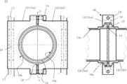
- Figure 2 shows an example of the configuration of the gas exhaust pipe 10.
- the left figure in Figure 2 is an explanatory diagram of the configuration as seen from the axial direction of the gas exhaust pipe 10, and the right figure is an explanatory diagram of the configuration in the A-A' cross section of the left figure.
- the gas exhaust pipe 10 mainly includes a plurality of pipes 12 (12a, 12b), a liquid-coolable pipe clamp 13, and a seal material 14.
- the pipe 12 itself only needs to have a joint (such as a flange) 15 at its end.
- a step is provided from the pipe body to the joint 15, but the shape of the pipe 12 of the present invention is not limited to this, and this step does not need to exist.
- the sealing material 14 may be, for example, an O-ring, but is not limited to this. 2, the joints 15 of adjacent pipes 12 (12a, 12b) face each other with a sealant 14 sandwiched therebetween.
- the opposed joints 15 are sandwiched between clamps 18 of pipe clamps 13, thereby connecting the adjacent pipes 12 to each other.
- the solid and dotted circular lines are drawn approximately concentrically, and represent the pipe 12 and the clamp portion 18.
- the innermost solid circular line in the left diagram represents the inner peripheral surface 12s of the pipe 12 shown in the right diagram
- the dotted circular line in the left diagram represents the inner bottom surface 18s of the clamp portion 18 shown in the right diagram.
- the pipe clamp 13 can be made detachable from the pipe 12 (joint 15). Being detachable makes both the pipe clamp 13 itself and the pipe 12 itself easier to handle, and makes it easier to clean the inside of the pipe 12.
- it can have a two-piece structure (13a, 13b) as shown in the left diagram of Figure 2, and is made of a material with good thermal conductivity (e.g. aluminum).
- the number of parts is not particularly limited, and can be determined appropriately depending on the thickness of the pipe 12, etc.
- the pipe clamp 13 also has a liquid cooling mechanism that uses the flow of cooling water, and is provided with, for example, a through hole 16 for flowing cooling water inside.
- the inlet of the through hole 16 has a tapered screw shape for connecting a cooling water supply pipe 17 from the outside.
- the inlet of the through hole 16 has an internal thread
- the cooling water supply pipe 17 to be inserted therein has an external thread.
- the size (thickness) of the through hole 16 is not particularly limited, but may be, for example, 40 to 50% of the thickness of the piping clamp 13. With the through hole 16 having such a thickness, more efficient liquid cooling is possible.
- the tapered threads male thread, female thread
- the joints 15 of the multiple pipes 12 (12a, 12b) are opposed to each other with an O-ring or the like sandwiched between them as a sealant 14, and the two-part pipe clamps 13a, 13b are brought together from the left and right to the outer periphery of the opposed joints 15 as shown in the left diagram of Fig. 2. Then, as shown in the right diagram of Fig. 2, the opposed joints 15 are inserted into the clamp parts 18 of the pipe clamps 13a, 13b and fitted together, and the pipe clamps 13a, 13b are tightened with bolts 19 to seal them as shown in the left diagram of Fig. 2. In the left diagram of Fig.
- a cooling water supply pipe 17 is connected to the pipe clamp 13, and although the cooling water is passed from the top to the bottom in the case of Fig. 2, the opposite direction is also possible.
- the temperature of the cooling water can be, for example, about 20°C, but is not limited to this.
- the temperature of the cooling water can be appropriately determined depending on the temperature of the gas in the gas exhaust pipe 10 and the distance from the chamber 2.
- the passage of the cooling water liquid-cools the pipe clamp 13 itself, and effectively cools the seal material 14 between the joints 15 sandwiched by the pipe clamp 13.
- the cooling mechanism for gas exhaust piping in conventional equipment water cooling was performed using water-cooled piping welded to the outer circumference of the pipe body located on both sides of the joints of multiple pipes (with sealing material in between).
- the cooling mechanism in the manufacturing equipment of the present invention uses liquid-cooled piping clamps that clamp the joints of the pipes (with sealing material in between), and liquid-cools the piping clamps with cooling water to cool the joints they are holding, as well as the sealing material between them.
- the piping itself is lighter and easier to handle than before, and the sealing material can be cooled more effectively than before, preventing deterioration of the sealing material due to the heat of the high-temperature gas passing through the gas exhaust piping.
- This not only makes it easier to clean deposits inside the piping, but also prevents gas leaks due to deterioration of the sealing material.
- This reduces the cost of maintenance such as various tasks such as inspections when leaks occur and replacement of sealing material, and prevents the quality of the silicon single crystals produced from being reduced due to gas leaks.
- the present invention is not limited to the above-described embodiments.
- the above-described embodiments are merely examples, and anything that has substantially the same configuration as the technical idea described in the claims of the present invention and exhibits similar effects is included within the technical scope of the present invention.
Landscapes
- Chemical & Material Sciences (AREA)
- Engineering & Computer Science (AREA)
- Crystallography & Structural Chemistry (AREA)
- Materials Engineering (AREA)
- Metallurgy (AREA)
- Organic Chemistry (AREA)
- Crystals, And After-Treatments Of Crystals (AREA)
Abstract
本発明は、石英ルツボと、該石英ルツボ内のシリコン多結晶原料を加熱溶融して原料融液とするヒーターとが内部に配置されるチャンバーと、ガス導入配管と、ガス排気配管とを備えており、CZ法によってシリコン単結晶を製造する装置であって、ガス排気配管は、各々が継ぎ手部を有する複数の配管と、冷却水の通水により液冷可能な配管クランプとを有しており、複数の配管の継ぎ手部同士がシール材を間に挟んで対向しており、かつ、該対向した継ぎ手部同士が前記配管クランプにより挟まれていることで、複数の配管同士が接続されており、配管クランプの液冷により、継ぎ手部同士の間のシール材の冷却が可能なものであるシリコン単結晶製造装置である。これにより、ガス排気配管が取り回し易く、配管同士の間のシール材の劣化を防止することができるCZシリコン単結晶製造装置が提供される。
Description
本発明はチョクラルスキー法(CZ法)によりシリコン単結晶を製造する装置に関する。
半導体集積回路の基本材料であるシリコン単結晶の製造方法としてチョクラルスキー法がある。CZ法においてはチャンバー内に設けられた石英ルツボ内に高純度のシリコン多結晶原料を投入し、石英ルツボの外周に配置されたヒーターにより加熱してシリコン多結晶原料を溶融させる。この原料融液(シリコン溶融液)に種結晶を浸し、該種結晶を回転しながら引上げることで単結晶を成長させ、円柱状のシリコン単結晶が製造される。
CZ法では、シリコン単結晶の製造装置(引上げ機)にガス排気配管を介して真空ポンプが接続されており、真空ポンプにより、引上げ機に導入された不活性ガス(例えばArガス)を吸引する構成が排気方法として知られている(特許文献1)。
上記のような構成での製造装置においては、ガス排気配管は複数の配管が接続されて成っており、その継ぎ手部の間にシール材(例えばOリング)を介して接続されている。そしてシリコン単結晶を製造する場合、チャンバー内の不活性ガスはヒーターによって加熱されるため、不活性ガスは高温となる。高温となった不活性ガスを真空ポンプにて排気するが、ガス排気配管の継ぎ手部を介し、シール材に熱が伝わり劣化し、シリコン単結晶製造中に不活性ガスがリークする恐れがある。リークがある場合、シリコン単結晶製造装置のチャンバー内の真空が保たれず、品質に影響を及ぼす場合がある。
リークが発生した場合、リーク発生箇所の特定とシール材の交換を行う必要があるが、配管継ぎ手部は多数あるため、点検には時間を要し、その間はシリコン単結晶を製造することができない。
また、シリコン単結晶製造中にはシリコン酸化物が発生し、ガス排気配管内にシリコン酸化物が堆積する為、シリコン単結晶の製造後にはガス排気配管を取り外してシリコン酸化物を除去している。掃除のため、ガス排気配管(複数の配管)は軽量で取り回しやすく、且つ取り外しの容易な構造が望まれていた。
図3は従来技術のガス排気配管110の冷却機構の一例を示した説明図である。図3の左図はガス排気配管110の軸方向から見た構成説明図であり、右図は左図のB-B’の断面における構成説明図である。隣接する2つの配管112(112a、112b)の継ぎ手部115同士がシール材114を介して円環状に2分割された配管クランプ113(113a、113b)をボルトで締め付けることにより接続されている。従来技術では継ぎ手部115が高温にならないようにガス排気配管110の管本体(つまり、配管112の管本体)の外周に水冷配管120を巻き付けて溶接しており、水冷配管120に通水することでガス排気配管110が高温にならないようにしていた。
前記従来技術の手法ではガス排気配管の管本体の外周部を冷却するため、継ぎ手部やシール材付近は冷却されにくいことからシール材を熱で劣化させる場合があった。また、ガス排気配管の掃除の際にはばらして配管を取り外す必要がある。しかし配管には上記のように水冷配管を溶接しているため重く、作業性が悪化する。
本発明は上記課題を解決するためになされたもので、ガス排気配管が取り回し易く、配管同士の間のシール材の劣化を防止することができるCZシリコン単結晶製造装置を提供することを目的とする。
上記目的を達成するために、本発明は、シリコン多結晶原料を収容する石英ルツボと、該石英ルツボ内の前記シリコン多結晶原料を加熱溶融して原料融液とするヒーターとが内部に配置されるチャンバーと、
該チャンバー内に不活性ガスを導入するためのガス導入配管と、
前記チャンバー内に導入された前記不活性ガスを排気するためのガス排気配管とを備えており、
前記原料融液からチョクラルスキー法によってシリコン単結晶を製造するシリコン単結晶製造装置であって、
前記ガス排気配管は、各々が継ぎ手部を有する複数の配管と、冷却水の通水により液冷可能な配管クランプとを有しており、
前記複数の配管の継ぎ手部同士がシール材を間に挟んで対向しており、かつ、該対向した継ぎ手部同士が前記配管クランプにより挟まれていることで、前記複数の配管同士が接続されており、
前記配管クランプの液冷により、前記継ぎ手部同士の間の前記シール材の冷却が可能なものであることを特徴とするシリコン単結晶製造装置を提供する。
該チャンバー内に不活性ガスを導入するためのガス導入配管と、
前記チャンバー内に導入された前記不活性ガスを排気するためのガス排気配管とを備えており、
前記原料融液からチョクラルスキー法によってシリコン単結晶を製造するシリコン単結晶製造装置であって、
前記ガス排気配管は、各々が継ぎ手部を有する複数の配管と、冷却水の通水により液冷可能な配管クランプとを有しており、
前記複数の配管の継ぎ手部同士がシール材を間に挟んで対向しており、かつ、該対向した継ぎ手部同士が前記配管クランプにより挟まれていることで、前記複数の配管同士が接続されており、
前記配管クランプの液冷により、前記継ぎ手部同士の間の前記シール材の冷却が可能なものであることを特徴とするシリコン単結晶製造装置を提供する。
このような本発明のシリコン単結晶製造装置であれば、配管クランプの液冷により、ガス排気配管での継ぎ手部同士の間のシール材を効果的に冷却することができ、シール材の熱による劣化を防止することができる。このため、従来装置においてシール材の劣化により必要となっていた、リーク点検、シール材の交換の必要性を無くす、あるいは少なくともその頻度を低減することができる。その結果、整備コストを下げることができるし、リーク発生を起因とするシリコン単結晶の品質低下が生じるのを防いでシリコン単結晶の製造ロスを低減することができる。
また、従来装置のようにシール材の劣化防止用として水冷配管を配管の管本体の外周に溶接しなくとも十分にシール材を冷却することができるため、ガス排気配管を構成する複数の配管自体の軽量化を図ることができて取り回し易い。したがって配管内の堆積物の除去の際でも簡便に作業をすることができる。しかも、この液冷型の配管クランプを用いた改造費用の方が、従来の水冷タイプ(配管外周への水冷配管の溶接)の改造費用よりも安くすることができる。
本発明のシリコン単結晶製造装置であれば、ガス排気配管におけるシール材の熱による劣化を防止することができる。そのため、劣化したシール材を起因とするガスのリークの発生を防ぐことができ、リークに伴う各種の作業の必要性やそれに要するコストの発生、単結晶品質の低下を防ぐことができる。しかも、配管自体も軽量なものとなり、配管内の掃除において作業性を向上させることができる。
図1に本発明のチョクラルスキー法によるシリコン単結晶製造装置の一例を示す。このシリコン単結晶製造装置1は、チャンバー2を有している。チャンバー2内に配置された黒鉛ルツボ3内の石英ルツボ4の内部に原料融液5が満たされており、シリコン単結晶6はこの原料融液5から引き上げられる。原料融液5を加熱するためのヒーター7はチャンバー2内で黒鉛ルツボ3の外周に設置され、このヒーター7の外周にはヒーター7からの熱を断熱するために断熱部材8が設置されている。
またチャンバー2の上部にはガス導入配管9が配設されており、下部にはガス排気配管10が配設されている。そしてそのガス排気配管10の先には真空ポンプ11が接続されている。ガス導入配管9からはチャンバー2内を満たすアルゴン等の不活性ガスが導入され、そのガスは下方へ流動し、ガス排気配管10を通して真空ポンプ11によって外部へ排気されるようになっている。
シリコン単結晶6の製造の際には、まず、シリコン多結晶原料を石英ルツボ4内に収容し、ヒーター7による加熱で原料融液5にする。ワイヤで吊るした種結晶Sを原料融液5に浸漬した後にワイヤを引き上げてシリコン単結晶6を育成する。なお、チャンバー2内にはガス導入配管9から不活性ガスを導入するとともに、ガス排気配管10から排出している。
ここで本発明のシリコン単結晶製造装置1におけるガス排気配管10の構成について説明する。図2にガス排気配管10の構成の一例を示す。図2の左図はガス排気配管10の軸方向から見た構成説明図であり、右図は左図のA-A’の断面における構成説明図である。
ガス排気配管10は主に複数の配管12(12a、12b)、液冷可能な配管クランプ13、シール材14を有している。
配管12自体は端部に継ぎ手部(フランジなど)15を有していればよい。図2では特に右図からわかるように管本体から継ぎ手部15にかけて段差が設けられているが、本発明の配管12の形状はこれに限定されず、この段差が存在していなくともよい。
またシール材14としては例えばOリングが挙げられるがこれに限定されない。
図2の左図に示すように、隣接する複数の配管12(12a、12b)において、それぞれの継ぎ手部15同士がシール材14を間に挟んだ状態で対向している。そして右図に示すように、その対向した継ぎ手部15同士が配管クランプ13のクランプ部18により挟まれていることで、隣接する複数の配管12同士が接続されている。
なお、左図において円形の実線および点線がほぼ同心円状に描かれているが、これらは配管12やクランプ部18の部位を表している。左図の最内周の円形の実線は右図に示す配管12の内周面12sを表しており、左図の最外周の円形の点線は右図に示すクランプ部18の内底面18sを表している。
配管12自体は端部に継ぎ手部(フランジなど)15を有していればよい。図2では特に右図からわかるように管本体から継ぎ手部15にかけて段差が設けられているが、本発明の配管12の形状はこれに限定されず、この段差が存在していなくともよい。
またシール材14としては例えばOリングが挙げられるがこれに限定されない。
図2の左図に示すように、隣接する複数の配管12(12a、12b)において、それぞれの継ぎ手部15同士がシール材14を間に挟んだ状態で対向している。そして右図に示すように、その対向した継ぎ手部15同士が配管クランプ13のクランプ部18により挟まれていることで、隣接する複数の配管12同士が接続されている。
なお、左図において円形の実線および点線がほぼ同心円状に描かれているが、これらは配管12やクランプ部18の部位を表している。左図の最内周の円形の実線は右図に示す配管12の内周面12sを表しており、左図の最外周の円形の点線は右図に示すクランプ部18の内底面18sを表している。
配管クランプ13は配管12(継ぎ手部15)から着脱可能なものとすることができる。着脱可能であることで、配管クランプ13自体も配管12自体も共に取り扱いやすくなるし、配管12の内部を掃除する際に簡便である。一例としては図2の左図に示すように二分割構造のものとすることができ(13a、13b)、熱伝導率の良い材質(例えばアルミニウム)で製作されている。もちろん分割数は特に限定されず、配管12の太さ等により適宜決定することができる。
また配管クランプ13には冷却水の通水による液冷機構を有しており、例えば冷却水を内部に流すための貫通穴16が設けられている。そして貫通穴16の入口は、外部から冷却水送液配管17を接続するためのテーパーネジ形状となっている。つまり、貫通穴16の入口がめねじになっており、そこに挿入する冷却水送液配管17がおねじになっている。
貫通穴16の大きさ(太さ)は特に限定されないが、例えば配管クランプ13の厚さの40~50%のサイズとすることができる。貫通穴16の太さがこの程度あれば、より効率の良い液冷が可能である。また、テーパーネジ(おねじ、めねじ)については互いにそのサイズに合ったものとすることができる。
図2の貫通穴16は上下に通水させる直線形状となっているが、この形状も特に限定されず、冷却の効率性等を考慮して種々の形状とすることができる。
なお、ここでは貫通穴16と冷却水送液配管17とを接続するタイプについて説明したが、これとは別に例えば冷却水送液配管17を配管クランプ13の内部に貫通させるタイプとすることもできる。
貫通穴16の大きさ(太さ)は特に限定されないが、例えば配管クランプ13の厚さの40~50%のサイズとすることができる。貫通穴16の太さがこの程度あれば、より効率の良い液冷が可能である。また、テーパーネジ(おねじ、めねじ)については互いにそのサイズに合ったものとすることができる。
図2の貫通穴16は上下に通水させる直線形状となっているが、この形状も特に限定されず、冷却の効率性等を考慮して種々の形状とすることができる。
なお、ここでは貫通穴16と冷却水送液配管17とを接続するタイプについて説明したが、これとは別に例えば冷却水送液配管17を配管クランプ13の内部に貫通させるタイプとすることもできる。
ガス排気配管10を組み立てる際は、複数の配管12(12a、12b)の継ぎ手部15同士をそれらの間にシール材14としてOリング等を挟み込んだ状態で対向させ、その対向させた継ぎ手部15同士の外周に対し、図2の左図に示すように二分割されている配管クランプ13a、13bを左右から寄せる。そして図2の右図に示すように、配管クランプ13a、13bのクランプ部18内に、対向させた継ぎ手部15同士を挿入して嵌め合わせ、図2の左図に示すように配管クランプ13a、13b同士をボルト19で締め付けることでシールする。図2の左図では左右の2つの配管クランプ13a、13bとの隙間に継ぎ手部15が見えている。
そして配管クランプ13に冷却水送液配管17を接続し、図2の場合では冷却水を上側から下側へと通水するが、逆方向であっても良い。なお冷却水の温度は例えば20℃程度とすることができるが、この限りではない。冷却水の温度は、ガス排気配管10内のガスの温度やチャンバー2からの距離等に応じて適宜決定することができる。この冷却水の通水によって配管クランプ13自体が液冷され、該配管クランプ13が挟んでいる継ぎ手部15同士の間のシール材14を効果的に冷却可能である。
そして配管クランプ13に冷却水送液配管17を接続し、図2の場合では冷却水を上側から下側へと通水するが、逆方向であっても良い。なお冷却水の温度は例えば20℃程度とすることができるが、この限りではない。冷却水の温度は、ガス排気配管10内のガスの温度やチャンバー2からの距離等に応じて適宜決定することができる。この冷却水の通水によって配管クランプ13自体が液冷され、該配管クランプ13が挟んでいる継ぎ手部15同士の間のシール材14を効果的に冷却可能である。
従来装置のガス排気配管における冷却機構では、複数の配管の継ぎ手部同士(シール材が介在)の両側に位置する管本体の外周に溶接した水冷配管を利用して水冷していた。しかしながら、本発明の製造装置での冷却機構は上述したように配管の継ぎ手部同士(シール材が介在)を挟み込む配管クランプを液冷タイプのものとし、該配管クランプを冷却水により液冷することで、把持している継ぎ手部同士、さらにはその間のシール材を冷却するものである。
ガス排気配管がこのような冷却機構を備えていることで、従来よりも配管自体の軽量性や取り回し性が優れているとともに、従来よりも極めて効果的にシール材を冷却可能であり、ガス排気配管を通る高温ガスの熱によるシール材の劣化を防ぐことができる。このため、配管内の堆積物の掃除作業が楽になるだけでなく、シール材の劣化のせいでガスのリークが発生するのを防止可能である。したがってリークが発生した場合の点検等の種々の作業やシール材の交換などの整備コストを削減することができるし、製造するシリコン単結晶の品質がガスリーク起因で低下してしまうのを防ぐことができる。
なお、本発明は、上記実施形態に限定されるものではない。上記実施形態は例示であり、本発明の特許請求の範囲に記載された技術的思想と実質的に同一な構成を有し、同様な作用効果を奏するものは、いかなるものであっても本発明の技術的範囲に包含される。
Claims (1)
- シリコン多結晶原料を収容する石英ルツボと、該石英ルツボ内の前記シリコン多結晶原料を加熱溶融して原料融液とするヒーターとが内部に配置されるチャンバーと、
該チャンバー内に不活性ガスを導入するためのガス導入配管と、
前記チャンバー内に導入された前記不活性ガスを排気するためのガス排気配管とを備えており、
前記原料融液からチョクラルスキー法によってシリコン単結晶を製造するシリコン単結晶製造装置であって、
前記ガス排気配管は、各々が継ぎ手部を有する複数の配管と、冷却水の通水により液冷可能な配管クランプとを有しており、
前記複数の配管の継ぎ手部同士がシール材を間に挟んで対向しており、かつ、該対向した継ぎ手部同士が前記配管クランプにより挟まれていることで、前記複数の配管同士が接続されており、
前記配管クランプの液冷により、前記継ぎ手部同士の間の前記シール材の冷却が可能なものであることを特徴とするシリコン単結晶製造装置。
Priority Applications (3)
| Application Number | Priority Date | Filing Date | Title |
|---|---|---|---|
| KR1020257042859A KR20260026499A (ko) | 2023-06-28 | 2024-06-14 | 실리콘 단결정 제조장치 |
| DE112024002116.6T DE112024002116T5 (de) | 2023-06-28 | 2024-06-14 | Vorrichtung zur Herstellung von Siliziumeinkristallen |
| CN202480041796.7A CN121368653A (zh) | 2023-06-28 | 2024-06-14 | 硅单晶制造装置 |
Applications Claiming Priority (2)
| Application Number | Priority Date | Filing Date | Title |
|---|---|---|---|
| JP2023-105906 | 2023-06-28 | ||
| JP2023105906A JP7460010B1 (ja) | 2023-06-28 | 2023-06-28 | シリコン単結晶製造装置 |
Publications (1)
| Publication Number | Publication Date |
|---|---|
| WO2025004850A1 true WO2025004850A1 (ja) | 2025-01-02 |
Family
ID=90474302
Family Applications (1)
| Application Number | Title | Priority Date | Filing Date |
|---|---|---|---|
| PCT/JP2024/021644 Ceased WO2025004850A1 (ja) | 2023-06-28 | 2024-06-14 | シリコン単結晶製造装置 |
Country Status (6)
| Country | Link |
|---|---|
| JP (1) | JP7460010B1 (ja) |
| KR (1) | KR20260026499A (ja) |
| CN (1) | CN121368653A (ja) |
| DE (1) | DE112024002116T5 (ja) |
| TW (1) | TW202509297A (ja) |
| WO (1) | WO2025004850A1 (ja) |
Citations (4)
| Publication number | Priority date | Publication date | Assignee | Title |
|---|---|---|---|---|
| JP2000327480A (ja) * | 1999-05-24 | 2000-11-28 | Toshiba Ceramics Co Ltd | 単結晶引上げ設備及びその操作方法 |
| JP2002068888A (ja) * | 2000-08-23 | 2002-03-08 | Shin Etsu Handotai Co Ltd | シリコン単結晶引上げ装置の解体方法および排ガス配管 |
| JP2009167073A (ja) * | 2008-01-11 | 2009-07-30 | Union Material Kk | 単結晶成長装置及び単結晶成長方法 |
| JP2012148906A (ja) * | 2011-01-17 | 2012-08-09 | Sumco Techxiv株式会社 | 単結晶引き上げ装置の生成物燃焼方法 |
-
2023
- 2023-06-28 JP JP2023105906A patent/JP7460010B1/ja active Active
-
2024
- 2024-06-14 CN CN202480041796.7A patent/CN121368653A/zh active Pending
- 2024-06-14 KR KR1020257042859A patent/KR20260026499A/ko active Pending
- 2024-06-14 WO PCT/JP2024/021644 patent/WO2025004850A1/ja not_active Ceased
- 2024-06-14 DE DE112024002116.6T patent/DE112024002116T5/de active Pending
- 2024-06-20 TW TW113122813A patent/TW202509297A/zh unknown
Patent Citations (4)
| Publication number | Priority date | Publication date | Assignee | Title |
|---|---|---|---|---|
| JP2000327480A (ja) * | 1999-05-24 | 2000-11-28 | Toshiba Ceramics Co Ltd | 単結晶引上げ設備及びその操作方法 |
| JP2002068888A (ja) * | 2000-08-23 | 2002-03-08 | Shin Etsu Handotai Co Ltd | シリコン単結晶引上げ装置の解体方法および排ガス配管 |
| JP2009167073A (ja) * | 2008-01-11 | 2009-07-30 | Union Material Kk | 単結晶成長装置及び単結晶成長方法 |
| JP2012148906A (ja) * | 2011-01-17 | 2012-08-09 | Sumco Techxiv株式会社 | 単結晶引き上げ装置の生成物燃焼方法 |
Also Published As
| Publication number | Publication date |
|---|---|
| CN121368653A (zh) | 2026-01-20 |
| TW202509297A (zh) | 2025-03-01 |
| KR20260026499A (ko) | 2026-02-26 |
| JP7460010B1 (ja) | 2024-04-02 |
| DE112024002116T5 (de) | 2026-03-05 |
| JP2025005649A (ja) | 2025-01-17 |
Similar Documents
| Publication | Publication Date | Title |
|---|---|---|
| TWI513848B (zh) | 混合氣體注射器 | |
| CN107671469B (zh) | 一种燃气轮机壳体的焊接工装和方法 | |
| WO2019144804A1 (zh) | 晶体生长用坩埚以及释放碳化硅晶体热应力的方法 | |
| JP4393555B2 (ja) | 単結晶成長方法 | |
| JP7460010B1 (ja) | シリコン単結晶製造装置 | |
| US8371007B2 (en) | Drain apparatus | |
| CN116377562B (zh) | 一种单晶炉及降低单晶炉中硅蒸汽的方法 | |
| US6605152B2 (en) | Catch pan for melt leakage in apparatus for pulling single crystal | |
| JPWO2001064976A1 (ja) | 単結晶引上げ装置の湯漏れ受皿 | |
| CN221460232U (zh) | 一种改善光棒拉伸炉石墨件高温损耗的装置及设备 | |
| TW202407263A (zh) | 管道用除粉裝置製造方法及設置方法 | |
| WO2002031234A1 (fr) | Appareil de croissance de cristal | |
| WO2024051210A1 (zh) | 一种单晶炉用换热器及单晶炉 | |
| CN204592648U (zh) | 一种用于低温流体管线中相邻真空管连接的连接结构 | |
| CN105986081A (zh) | 一种tp92钢热处理工艺 | |
| CN216919478U (zh) | 石英坩埚熔制聚热装置及石英坩埚熔制设备 | |
| CN103386548B (zh) | 线圈架扩散焊接方法 | |
| CN111876824A (zh) | 单晶炉主腔室上部导热系统及其控制方法 | |
| CN220318040U (zh) | 一种单晶炉冷却设备 | |
| CN114182088B (zh) | 降低管壳式换热器换热管与管板焊接接头应力腐蚀开裂风险的局部热处理方法 | |
| CN205027125U (zh) | 用于各类工业炉的管路与墙体套接结构 | |
| CN222294251U (zh) | 一种单晶炉腔体炉盖及压力容器 | |
| CN220373152U (zh) | 一种拆装工装 | |
| CN205258656U (zh) | 单晶炉冷却盘 | |
| CN205000007U (zh) | 水冷式真空泵卡头 |
Legal Events
| Date | Code | Title | Description |
|---|---|---|---|
| 121 | Ep: the epo has been informed by wipo that ep was designated in this application |
Ref document number: 24831715 Country of ref document: EP Kind code of ref document: A1 |
|
| WWE | Wipo information: entry into national phase |
Ref document number: 112024002116 Country of ref document: DE |
|
| WWP | Wipo information: published in national office |
Ref document number: 112024002116 Country of ref document: DE |