WO2025004840A1 - 情報処理装置、情報処理方法、及びプログラム - Google Patents
情報処理装置、情報処理方法、及びプログラム Download PDFInfo
- Publication number
- WO2025004840A1 WO2025004840A1 PCT/JP2024/021593 JP2024021593W WO2025004840A1 WO 2025004840 A1 WO2025004840 A1 WO 2025004840A1 JP 2024021593 W JP2024021593 W JP 2024021593W WO 2025004840 A1 WO2025004840 A1 WO 2025004840A1
- Authority
- WO
- WIPO (PCT)
- Prior art keywords
- imaging
- information
- subject
- information processing
- processing device
- Prior art date
- Legal status (The legal status is an assumption and is not a legal conclusion. Google has not performed a legal analysis and makes no representation as to the accuracy of the status listed.)
- Ceased
Links
Images








Classifications
-
- A—HUMAN NECESSITIES
- A61—MEDICAL OR VETERINARY SCIENCE; HYGIENE
- A61B—DIAGNOSIS; SURGERY; IDENTIFICATION
- A61B5/00—Measuring for diagnostic purposes; Identification of persons
-
- A—HUMAN NECESSITIES
- A61—MEDICAL OR VETERINARY SCIENCE; HYGIENE
- A61B—DIAGNOSIS; SURGERY; IDENTIFICATION
- A61B5/00—Measuring for diagnostic purposes; Identification of persons
- A61B5/02—Detecting, measuring or recording for evaluating the cardiovascular system, e.g. pulse, heart rate, blood pressure or blood flow
- A61B5/021—Measuring pressure in heart or blood vessels
-
- A—HUMAN NECESSITIES
- A61—MEDICAL OR VETERINARY SCIENCE; HYGIENE
- A61B—DIAGNOSIS; SURGERY; IDENTIFICATION
- A61B5/00—Measuring for diagnostic purposes; Identification of persons
- A61B5/02—Detecting, measuring or recording for evaluating the cardiovascular system, e.g. pulse, heart rate, blood pressure or blood flow
- A61B5/024—Measuring pulse rate or heart rate
-
- A—HUMAN NECESSITIES
- A61—MEDICAL OR VETERINARY SCIENCE; HYGIENE
- A61B—DIAGNOSIS; SURGERY; IDENTIFICATION
- A61B5/00—Measuring for diagnostic purposes; Identification of persons
- A61B5/08—Measuring devices for evaluating the respiratory organs
-
- A—HUMAN NECESSITIES
- A61—MEDICAL OR VETERINARY SCIENCE; HYGIENE
- A61B—DIAGNOSIS; SURGERY; IDENTIFICATION
- A61B5/00—Measuring for diagnostic purposes; Identification of persons
- A61B5/145—Measuring characteristics of blood in vivo, e.g. gas concentration or pH-value ; Measuring characteristics of body fluids or tissues, e.g. interstitial fluid or cerebral tissue
- A61B5/1455—Measuring characteristics of blood in vivo, e.g. gas concentration or pH-value ; Measuring characteristics of body fluids or tissues, e.g. interstitial fluid or cerebral tissue using optical sensors, e.g. spectral photometrical oximeters
Definitions
- the present invention relates to an information processing device, an information processing method, and a program for acquiring biological information of a subject.
- a technique that detects the subject's biosignal based on moving images obtained by imaging the subject. For example, when measuring pulse rate as bioinformation, a pulse waveform is detected as a biosignal. The pulse rate can then be calculated from the number of peaks in the pulse waveform within a certain period of time.
- Patent Document 1 discloses a method for acquiring biometric information based on moving images obtained by imaging a subject using an imaging device.
- the present invention aims to provide an information processing device that can acquire biological information of a subject with high accuracy.
- An information processing device that acquires biometric information of a subject based on at least one moving image obtained by imaging the subject using multiple imaging devices with different imaging areas, and is characterized by comprising a first acquisition unit that acquires at least one moving image, a second acquisition unit that acquires information regarding changes in the imaging environment, a selection unit that selects an imaging device to be used to acquire the biometric information from the multiple imaging devices based on the information, and a third acquisition unit that acquires the biometric information of the subject based on the moving image obtained using the selected imaging device.
- the present invention provides an information processing device that can acquire biological information of a subject with high accuracy.
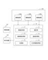
- FIG. 1 is a block diagram of an information processing apparatus according to a first embodiment.
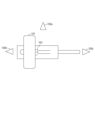
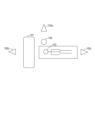
- FIG. 2 is a diagram showing the relationship between an imaging device, a test object, and an inspection device.
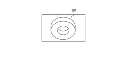
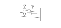
- 3 is a diagram showing an example of an image obtained by the imaging device in FIG. 2.
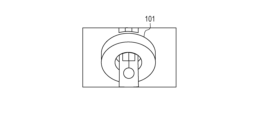
- 3 is a diagram showing an example of an image obtained by the imaging device in FIG. 2.
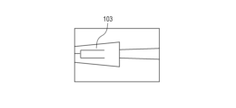
- 3 is a diagram showing an example of an image obtained by the imaging device in FIG. 2.
- FIG. 2 is a diagram showing the relationship between an imaging device, a test object, and an inspection device during inspection.
- 5A and 5B are diagrams illustrating examples of images obtained by the imaging device in FIG. 4.
- 5A and 5B are diagrams illustrating examples of images obtained by the imaging device in FIG. 4.
- FIG. 5A and 5B are diagrams illustrating examples of images obtained by the imaging device in FIG. 4.
- 4 is a flowchart showing a processing operation of the information processing apparatus according to the first embodiment
- FIG. 11 is a block diagram of an information processing device according to a second embodiment.
- FIG. 2 is a diagram showing the relationship between an imaging apparatus, a subject, and a subject other than the subject.
- 9 is a diagram showing an example of an image obtained by the imaging device in FIG. 8 .
- 9 is a diagram showing an example of an image obtained by the imaging device in FIG. 8 .
- 9 is a diagram showing an example of an image obtained by the imaging device in FIG. 8 .
- 10 is a flowchart showing a processing operation of an information processing device according to a second embodiment.
- Hemoglobin in blood has a high absorption rate for light of 495 to 570 nm (green wavelength) and 800 to 1000 nm (infrared wavelength). Therefore, by acquiring the change over time in the amount of light (particularly green wavelength or infrared wavelength) reflected from a part of the subject's skin surface, including the subject's blood vessels, it is possible to detect the subject's biosignal.
- one of the following is acquired as bioinformation of the subject: pulse rate, blood pressure, respiratory rate, heart rate, and oxygen saturation.
- a known technique can be used to determine the subject's bioinformation based on the acquired biosignal of the subject.
- Signal processing of the biosignal according to the desired bioinformation among pulse rate, blood pressure, respiratory rate, heart rate, and oxygen saturation, and other processing are not limited to those in this embodiment.
- the biosignal may be calculated by taking a moving average of a waveform based on a photoplethysmogram (PPG) calculated from the brightness value in the moving image.
- the biosignal may include a green wavelength or an infrared wavelength in the moving image, and may be information based on the subject's condition, such as blood flow.
- the pulse rate can be found by detecting the peak positions from the biosignal (waveform) and calculating the interval between the peaks or the number of peaks within a certain time range.
- the pulse rate can be found from the peak frequency in the frequency characteristics obtained by Fourier transforming the biosignal.
- the peaks in the biosignal may be detected by a threshold value for the peak height or peak width in the biosignal.
- the respiratory rate can be found from the frequency characteristics obtained by applying a Fourier transform to a biosignal (waveform) based on the PPG. Alternatively, it can be found by calculating the interval between peaks in the waveform obtained by extracting a frequency band signal caused by breathing from the biosignal (waveform), or the number of peaks within a certain time range.
- the frequency band of the biosignal caused by breathing is lower in frequency than the frequency band of the biosignal caused by the pulse rate.
- each piece of bioinformation by determining the feature amount in the biosignal.
- the feature amount can be the shape of the waveform, such as multiple peaks in one waveform of the biosignal or a notch point just before the second peak.
- blood pressure can be obtained using pulse transit time (PTT) or pulse wave velocity (PWV).
- PTT pulse transit time
- PWV pulse wave velocity
- a stress index (LF/HF) can be calculated based on the high frequency component (HF) and low frequency component (LF) of the heart rate variability spectrum obtained by frequency converting the variation in the interval between the peaks of the biosignal.
- biometric information may be obtained using a machine learning model. It is estimated using machine learning from the above features and biometric signals.
- Methods for generating machine learning models include decision tree learning, support vector machines, and deep learning.
- Fig. 1 is a block diagram of an information acquisition system 1 according to the first embodiment.
- the information acquisition system 1 includes an information processing device 10, multiple imaging devices 100 (100a, 100b, and 100c) with different imaging areas, an inspection device 101, and a display device 102.
- the information processing device 10 can communicate with each of the multiple imaging devices 100, the inspection device 101, and the display device 102 via a wired connection or a network.
- the information processing device 10 in this embodiment has an information acquisition unit (first acquisition unit) 11, a selection unit 12, a moving image acquisition unit (second acquisition unit) 13, an area setting unit 14, a processing unit 15, and a biometric information acquisition unit (third acquisition unit) 16.
- the information processing device 10 is a device that measures biometric information based on a moving image made up of captured images (hereinafter, frame images) obtained by continuously capturing images of a subject from which biometric information is to be acquired using an imaging device 100.
- the function of acquiring the biometric information of the subject by the information processing device 10 can be implemented by one or more processors (processing means) such as CPUs.
- Each of the multiple imaging devices 100 has an optical system and an imaging element.
- the optical system collects light incident on the imaging element from the subject space.
- the imaging element receives an optical image of the subject formed through the optical system to obtain a moving image.
- the imaging element is a CCD (Charge Coupled Device) sensor, a CMOS (Complementary Metal-Oxide Semiconductor) sensor, or the like.
- the inspection device 101 is a device that inspects the subject 103.
- it is an inspection device that inspects the subject, such as a CT (Computed Tomography) device or an X-ray TV device. Note that multiple inspection devices may be set.
- CT Computer Planar Tomography
- X-ray TV device X-ray TV
- the inspection device 101 in this embodiment includes an inspection unit for performing an inspection on the subject other than biological information, an imaging unit having an image sensor for imaging the subject, and a communication unit (transmission unit) for communicating with the information processing device 10.
- the inspection device 101 may be one of the multiple imaging devices 100. This configuration is preferable because it allows the subject to be clearly imaged even during an inspection.
- either the information processing device 10 or the imaging device 100 may be configured as an integrated device, and an imaging unit having an imaging element and an optical system may be mounted on the information processing device 10.
- this may be a smartphone or a personal computer.
- either the inspection device 101 or the imaging device 100 may be configured as an integrated device, for example, an imaging unit having an imaging element and an optical system may be mounted on the inspection device 101.
- the multiple imaging devices 100 have an imaging device equipped with an imaging element that can detect not only light in the R (red), G (green), and B (blue) wavelength ranges, but also the IR (infrared light) wavelength range. With this configuration, it is possible to obtain biological information about the subject 103 even in an environment with dark illumination light. Also, since IR has a deep penetration depth into the interior of a living body, it is possible to obtain information about blood flow deep inside the body.
- the display device 102 is, for example, a liquid crystal display or a projector, and displays moving images captured using the imaging device 100 and measured biological information of the subject.
- the information acquisition system 1 according to this embodiment will be described with reference to Figures 2 to 6.
- FIGS. 3A to 3C and 5A to 5C are diagrams showing examples of imaging areas of the multiple imaging devices 100 with different imaging areas. A to C in each figure correspond to the imaging devices 100a, 100b, and 100c, respectively.
- the subject 103 is in the blind spot of the imaging device 100b by the examination device 101.
- the subject 103 can be imaged using the imaging device 100a and the imaging device 100c. Therefore, in the state of FIG. 2, it is preferable to obtain the subject's biological information based on the moving image obtained by the imaging device 100a or 100c.
- FIG. 4 shows a state in which the bed in the inspection device 101 has moved and the subject 103 has entered the gantry in the inspection device 101. Therefore, as shown in FIG. 5B, the subject 103 enters the blind spot of the imaging devices 100a and 100c by the inspection device 101. On the other hand, as shown in FIG. 5B, the subject 103 can be imaged using the imaging device 100b. Therefore, in the state of FIG. 4, it is preferable to acquire biological information of the subject based on the moving image acquired by the imaging device 100b.
- the information processing device 10 acquires information about changes in the imaging environment from the inspection device 101.
- the inspection device 101 has a transmission unit, and in this embodiment, the inspection device 101 transmits information about the operation according to the operation of the device to the information processing device 10 as information about changes in the imaging environment.
- signals of control instructions such as moving the bed and starting and ending the examination are transmitted.
- a control signal for the inspection device (external device) 101 may be acquired as information regarding changes in the imaging environment.
- a control unit (or control device) that controls the inspection device 101 transmits a signal (control signal) for controlling the inspection device 101, and the inspection device 101 operates in response to the control signal.
- the control unit may be included in the information processing device 10, or the inspection device 101 may be controlled using the control unit in the information processing device 10.
- control instruction signals such as moving the bed and starting and ending the examination can be acquired as control signals to the CT device as information regarding changes in the imaging environment.
- the information processing device 10 may acquire information regarding lighting as information regarding changes in the imaging environment.
- the information regarding changes in the imaging environment may be acquired based on the brightness value of the moving image from the imaging device, such as changes in lighting or whether the environment is bright or dark.
- a control signal for a lighting device (illumination device) for illuminating the subject, or the state of the lighting device, such as whether it is ON or OFF, may be acquired as information regarding changes in the imaging environment.
- the selection unit 12 selects an imaging device equipped with an imaging element capable of photoelectric conversion of light in the IR (infrared) wavelength range.
- FIG. 6 is a flowchart showing a method for acquiring biometric information in the biometric information processing device according to the first embodiment.
- step S10 the information acquisition unit 11 acquires information regarding changes in the imaging environment.
- the information regarding changes in the imaging environment is information regarding the operation of the inspection device 101.
- the selection unit 12 selects at least one imaging device that images the subject to acquire biometric information from the multiple imaging devices based on information regarding changes in the imaging environment.
- the selection unit 12 selects multiple imaging devices, for example, from three imaging devices, when selecting an imaging device based on information regarding changes in the imaging environment, the selection unit 12 selects two imaging devices that image the subject.
- the selection unit 12 may select one imaging device based on moving images acquired by the two imaging devices.
- the information regarding the change in the imaging environment will be described as being related to the change in the subject resulting from the transition from the state in FIG. 2 to the state in FIG. 4.
- the information acquisition unit 11 in this embodiment acquires information regarding the operation of the device from the inspection device 101 as information regarding the change in the imaging environment. Due to the operation of the inspection device 101, the subject 103 enters the blind spot of the imaging device 100a. At this time, the imaging device 100a is unable to acquire biological information about the subject 103. Therefore, the selection unit 12 in this embodiment selects at least one of the imaging devices 100a and 100c that can image the subject 103.
- the selection unit 12 may select a moving image (first moving image) to be used to acquire biometric information based on the number of pixels corresponding to the skin area of the subject 103 in the moving image, or an imaging device corresponding to the first moving image.
- the skin area of the subject 103 is the face, hands, feet, etc. of the subject 103.
- the selection unit 12 may select an imaging device according to a preset priority.
- the priority may be determined in advance, such as face > hands > feet, and after multiple imaging devices have been selected, an imaging device capturing an image of a body area with a high priority may be selected.
- step S12 the video acquisition unit 13 acquires a video obtained by capturing an image using the selected imaging device. Note that if multiple imaging devices (or multiple videos) are selected, the selection unit 12 may select one of the multiple imaging devices after this process.
- the region setting unit 14 detects a region of interest of the subject 103 to be used for acquiring biometric information based on the video.
- the region of interest is the subject's face, and is information determined to be a face region by performing face detection.
- the face region is not limited to the entire face defined based on feature points of types of face regions such as the eyes, nose, mouth, and facial contour, but may be a specific part such as the cheek or forehead.
- the selection unit 12 may select one of the multiple imaging devices after this process.
- step S14 the processing unit 15 obtains time series data, which is a biosignal, by extracting signal information (brightness values) within the region of interest of each frame image in the moving image.
- the processing unit 15 may obtain, as the biosignal, a signal obtained by performing moving average processing on the time series data obtained based on the moving image. With this configuration, it is possible to reduce noise components contained in the time series data.
- step S15 the bio-information acquisition unit 16 acquires bio-information from the acquired bio-signal.
- the bio-information acquisition unit 16 performs processing according to the target bio-information. For example, when obtaining heart rate or respiratory rate as bio-information, peaks (maximum or minimum values) in the bio-signal are detected, and the heart rate or respiratory rate is obtained based on the number of peaks within a certain period of time.
- Fig. 7 is a block diagram of an information acquisition system 2 according to the second embodiment.
- the information processing device 10 and the inspection device 101 are not communicatively connected.
- the information acquisition unit 11 in this embodiment acquires information regarding changes in the imaging environment based on moving images from the imaging device.
- the information regarding changes in the imaging environment in this embodiment is information regarding the movement of the subject 103 and subjects other than the subject 104, such as the subject 103 entering a blind spot of the imaging device.
- Subjects other than the subject include, for example, the examination device 101 and medical personnel (doctors, nurses, and laboratory technicians). Therefore, it is preferable that the imaging device that images the subject 103 is installed in a position where it can image all of the examination device, non-subjects such as doctors, and subjects.
- the information acquisition unit 11 can acquire information regarding changes in the imaging environment based on the moving image by detecting the movements and movements of subjects including the subject 103 in the moving image by block matching or the like of specific regions of the subject.
- movements of subjects other than the subject performed on the subject such as movements such as treatment by the subjects other than the subject, may be acquired as information regarding changes in the imaging environment.
- the information may be acquired as information regarding changes in the imaging environment such as treatment, or the movements of subjects other than the subject may be detected and acquired as information regarding changes in the imaging environment such as treatment.
- a specific movement of a subject other than the subject making a specific movement may be detected and acquired as information regarding changes in the imaging environment such as treatment.
- the information acquisition unit 11 may acquire a change in luminance value over time from the moving image as information related to a change in the imaging environment. If the luminance value in the moving image drops significantly, it is assumed that the amount of illumination light irradiated to the subject 103 has decreased.
- the selection unit 12 select an imaging device equipped with an imaging element capable of detecting light with wavelengths in the infrared range.
- audio data may be acquired as information regarding changes in the imaging environment.
- a preset keyword such as "treatment begins” may be detected and used as information regarding changes in the imaging environment.
- the audio data is acquired together with the moving image by the moving image acquisition unit 13.
- FIG. 8 is an image diagram of the subject 103, the object 104, the inspection device 101, and the multiple imaging devices 100 in this embodiment.
- FIGS. 9A to 9C are diagrams showing examples of the imaging areas of the multiple imaging devices 100 with different imaging areas. A to C in each figure correspond to the imaging devices 100a, 100b, and 100c, respectively.
- the subject 104 in this embodiment is a subject other than the subject 103, such as a medical professional (doctor, nurse, or technician).
- FIG. 8 shows a state in which the subject 104 has moved close to the subject 103.
- the subject 103 enters the blind spot of the imaging device 100a due to the subject 104.
- the subject 103 enters the blind spot of the imaging device 100b due to the inspection device 101.
- the subject 103 can be imaged using the imaging device 100c. Therefore, in the state of FIG. 8, it is preferable to acquire biological information of the subject based on the moving image acquired by the imaging device 100c.
- FIG. 10 is a flowchart showing a method for acquiring biometric information in the information processing device 10 according to the second embodiment.
- the information processing device 10 acquires moving images from at least one of the multiple imaging devices 100 before step S20 described below.
- the information processing device 10 in this embodiment acquires moving images (FIG. 3A) obtained by capturing images using the imaging device 100a in FIG. 2.
- step S20 the information acquisition unit 11 acquires information regarding changes in the imaging environment (changes in the subject).
- the information acquisition unit 11 acquires information regarding changes in the imaging environment based on the moving image obtained by the imaging device 100a.
- step S21 the information acquisition unit 11 determines whether or not information regarding changes in the imaging environment has been acquired, or whether or not the information regarding changes in the imaging environment has changed. If the information acquisition unit 11 acquires information regarding changes in the imaging environment or the information regarding changes in the imaging environment has changed, the process proceeds to step S22. If the information regarding changes in the imaging environment cannot be acquired or the information regarding changes in the imaging environment has not changed, there is no need to change the imaging device that acquires moving images to acquire biometric information, so step S22 is skipped and the process proceeds to step S23.
- the selection unit 12 selects at least one imaging device capable of imaging the skin area of the subject 103 from the multiple imaging devices 100 based on information about the change in the imaging environment.
- the information about the change in the imaging environment in this embodiment will be described as related to the change in the subject caused by changing from the state in FIG. 2 to the state in FIG. 8.
- the subject 103 enters the blind spot of the imaging device 100a due to the subject 104.
- the imaging device 100a cannot obtain biological information about the subject 103. Therefore, the selection unit 22 in this embodiment selects the imaging device 100c that can image the subject 103.
- the selection unit 12 may select a video image (first video image) to be used to acquire biometric information from the multiple video images acquired using different imaging devices. Steps S23 to S25 are the same as those in the first embodiment.
- step S26 the processing unit 15 determines whether time series data for the specified time has been acquired, and if the specified time has not been reached, executes the processing of each step again from step S20 to satisfy the specified time.
- the specified time is the time required to acquire bioinformation. For example, when acquiring bioinformation by Fourier transforming a biosignal, a moving image of several seconds to several tens of seconds is required, so the specified time is set appropriately depending on the number of samples required for conversion. If time series data for the specified time has been acquired, proceed to step S27.
- step S27 the bio-information acquisition unit 16 acquires bio-information of the subject 103 based on the obtained bio-signal.
- the information processing device 10 may repeatedly perform steps S20 to S27 to acquire biological information of the subject continuously over time.
- This embodiment can also be realized by a process in which a program for realizing one or more of the functions of the above-mentioned embodiments is supplied to a system or device via a network or a storage medium, and one or more processors in a computer of the system or device read and execute the program. It can also be realized by a circuit (e.g., ASIC) for realizing one or more of the functions.
- a circuit e.g., ASIC
- Embodiments of the present invention include the following configurations, methods, and programs.
- An information processing device for acquiring biological information of a subject based on at least one moving image obtained by imaging the subject using a plurality of imaging devices with different imaging areas, A first acquisition unit that acquires the at least one moving image; A second acquisition unit that acquires information regarding a change in the imaging environment; a selection unit that selects an imaging device to be used for acquiring the biometric information from the plurality of imaging devices based on the information; and a third acquisition unit that acquires biological information of the subject based on a moving image obtained by using a selected imaging device.
- the plurality of imaging devices include an imaging device having an imaging element capable of detecting light having a wavelength in the infrared range,
- the information processing device characterized in that the selection unit selects an imaging device having an imaging element capable of detecting light with a wavelength in the infrared range when an amount of illumination light irradiated to the subject is reduced by operation of the illumination device.
- Configuration 9 a setting unit that sets a region including the subject in the moving image as a region of interest, 9.
- the information processing apparatus according to any one of configurations 1 to 8, wherein the third acquisition unit acquires biological information of the subject based on the region of interest in the moving image.
- Configuration 10 The information processing device described in configuration 2, characterized in that the selection unit selects a plurality of imaging devices that image a skin region of the subject based on the information on the subject, and selects an imaging device that acquires biological information based on a region of the subject in a plurality of moving images acquired by the plurality of imaging devices.
- Configuration 13 The information processing device according to any one of configurations 1 to 12, wherein the biological information includes at least one of a pulse rate, a blood pressure, a respiratory rate, a heart rate, and an oxygen saturation level of the subject.
- An imaging apparatus comprising: the information processing apparatus according to any one of configurations 1 to 13; and an imaging element for imaging the subject.
- An information acquisition system having the information processing device according to any one of configurations 1 to 13 and an inspection device capable of communicating with the information processing device,
- the information acquisition system according to the present invention is characterized in that the inspection device has a transmission unit that transmits the information to the information processing device in response to an operation of the inspection device.
- An information acquisition system including the information processing device according to any one of configurations 1 to 13 and the plurality of imaging devices capable of communicating with the information processing device, 2.
- An information acquisition system comprising: a plurality of imaging devices each having a transmission unit for transmitting a moving image to the information processing device.
- Method 1 An information processing method for acquiring biological information of a subject based on at least one moving image obtained by imaging the subject using a plurality of imaging devices with different imaging areas, comprising: acquiring said at least one motion picture; acquiring information regarding a change in an imaging environment; selecting an imaging device to be used for acquiring the biometric information from the plurality of imaging devices based on the information; and acquiring biological information of the subject based on a moving image obtained using a selected imaging device.
- Program 1 A program for causing a computer to execute the information processing method according to Method 1.
- the inspection device includes: An inspection unit for inspecting the subject; an imaging unit having an imaging element for imaging the subject; and a transmitting unit configured to transmit information regarding a change in the imaging environment to the information processing device.
- Reference Signs List 10 Information processing device 11 First acquisition unit 12 Selection unit 13 Second acquisition unit 16 Third acquisition unit
Landscapes
- Health & Medical Sciences (AREA)
- Life Sciences & Earth Sciences (AREA)
- Physics & Mathematics (AREA)
- Heart & Thoracic Surgery (AREA)
- Molecular Biology (AREA)
- Veterinary Medicine (AREA)
- Biophysics (AREA)
- Pathology (AREA)
- Engineering & Computer Science (AREA)
- Biomedical Technology (AREA)
- Public Health (AREA)
- Medical Informatics (AREA)
- General Health & Medical Sciences (AREA)
- Surgery (AREA)
- Animal Behavior & Ethology (AREA)
- Cardiology (AREA)
- Physiology (AREA)
- Vascular Medicine (AREA)
- Spectroscopy & Molecular Physics (AREA)
- Optics & Photonics (AREA)
- Pulmonology (AREA)
- Measuring And Recording Apparatus For Diagnosis (AREA)
- Measurement Of The Respiration, Hearing Ability, Form, And Blood Characteristics Of Living Organisms (AREA)
Abstract
撮像領域の異なる複数の撮像装置を用いて被検体を撮像することで得られた少なくとも一つの動画像に基づいて該被検体の生体情報を取得する情報処理装置であって、少なくとも一つの動画像を取得する第1取得部11と、撮像環境の変化に関する情報を取得する第2取得部13と、情報に基づいて、複数の撮像装置から生体情報を取得するために用いる撮像装置を選択する選択部12と、選択された撮像装置を用いて得られた動画像に基づいて被検体の生体情報を取得する第3取得部16とを備える。
Description
本発明は、被検体の生体情報を取得する情報処理装置、情報処理方法及びプログラムに関する。
被検体に対して非接触で生体情報を取得するために、被検体を撮像することで得られた動画像に基づいて被検体の生体信号を検出する技術が知られている。例えば、生体情報として脈拍数を測定する場合、生体信号として脈波形を検出する。そして、一定時間内の脈波形におけるピーク数から脈拍数を求めることができる。被検体に対して非接触で被検体の生体情報を取得することで、被検体にかかるストレスを低減することができる。
特許文献1には、撮像装置を用いて被検体を撮像することで得られた動画像に基づいて生体情報を取得する方法が開示されている。
しかしながら、特許文献1に開示された方法を用いて被検体の生体情報を取得するとき、被検体が撮像装置の死角に入ると被検体の生体情報を取得することができない。例えば、病院における検査室や処置室において非接触で被検体の生体情報を取得する場合、検査装置や医療従事者(医師、看護師、又は検査技師)等の被検体以外の被写体によって被検体が撮像装置の死角に入るおそれがある。結果として、被検体の生体情報を精度よく取得することができない。一方で、撮像領域の異なる複数の撮像装置を用いて被検体を撮像することで得られた複数の動画像のそれぞれに基づいて被検体の複数の生体情報を取得する処理を行う方法も考えられるが、処理が煩雑になるため好ましくない。
そこで本発明は、被検体の生体情報を高精度に取得可能な情報処理装置を提供することを目的とする。
撮像領域の異なる複数の撮像装置を用いて被検体を撮像することで得られた少なくとも一つの動画像に基づいて該被検体の生体情報を取得する情報処理装置であって、少なくとも一つの動画像を取得する第1取得部と、撮像環境の変化に関する情報を取得する第2取得部と、情報に基づいて、複数の撮像装置から生体情報を取得するために用いる撮像装置を選択する選択部と、選択された撮像装置を用いて得られた動画像に基づいて被検体の生体情報を取得する第3取得部とを備えることを特徴とする。
本発明によれば、被検体の生体情報を高精度に取得可能な情報処理装置を提供することができる。
以下、本発明の好ましい実施形態について図面を参照しながら説明する。なお、各図面は、便宜的に実際とは異なる縮尺で描かれている場合がある。また、各図面に示すように、同一の部材については同一の参照番号を付し、重複する説明を省略する。なお、以下の実施形態は特許請求の範囲に係る発明を限定するものではない。実施形態には複数の特徴が記載されているが、これらの複数の特徴の全てが発明に必須のものとは限らず、また、複数の特徴は任意に組み合わせられてもよい。
被検体に対して非接触で被検体の生体情報を取得するために、被検体の皮膚表面からの反射光の時系列データを生体信号として検出する技術がある。被検体としての生物の血管の血流量は、脈拍や呼吸に応じて周期的に増減している。これは、血液に含まれるヘモグロビンの光に対する吸収率の特性に起因する。
血液中のヘモグロビンは、495~570nm(緑色の波長)及び800~1000nm(赤外域の波長)の光に対する吸収率が高い。そのため、被検体の血管を含む皮膚表面の一部からの反射光の光量(特に、緑色の波長又は赤外域の波長)の時間に対する変化を取得することで、被検体の生体信号を検出することができる。本実施形態において被検体の生体情報として脈拍数、血圧、呼吸数、心拍数、及び酸素飽和度のいずれか一つを取得する。
取得された被検体の生体信号に基づいて、該被検体の生体情報を求める方法に関しては、公知の技術を用いることができる。脈拍数、血圧、呼吸数、心拍数、及び酸素飽和度のうち目的とする生体情報に応じた生体信号の信号処理やその他の処理に関して、本実施形態において限定されるものではない。
例えば、生体信号(波形)は、動画像における輝度値から求められた光電式容積脈波(photoplethysmogram:PPG)に基づいた波形の移動平均によって求められていてもよい。また、生体信号は動画像における緑色の波長若しくは赤外域の波長を含み、血流量など被検体の状態に基づいている情報であればよい。
脈拍数は生体信号(波形)からピーク位置を検出し、ピークの間隔や、一定の時間範囲内でのピーク数を算出することにより求められる。あるいは生体信号をフーリエ変換して得られる周波数特性におけるピーク周波数から脈拍数を求めることもできる。また、生体信号におけるピークは、生体信号におけるピーク高さまたはピーク幅に対するしきい値によって検出されてもよい。
呼吸数は、PPGに基づいた生体信号(波形)に対して、フーリエ変換して得られる周波数特性から求めることができる。あるいは、生体信号(波形)に対して、呼吸に起因する周波数帯域の信号を抽出した波形のピークの間隔や、一定の時間範囲内でのピーク数を算出することにより求められる。呼吸に起因する生体信号の周波数帯域は、脈拍に起因する生体信号の周波数帯域よりも低周波になる。
なお、生体信号における特徴量を求め、各生体情報を取得してもよい。特徴量として例えば、生体情報が血圧であれば、生体信号である1波形の複数のピークや第2ピーク手前のノッチ点等の波形の形状を特徴量として用いることができる。あるいは、脈波伝播時間(pulse transit time:PTT)や脈波伝搬速度(pulse wave velocity:PWV)などを用いて血圧を取得することができる。また、生体情報が心拍変動であれば、生体信号のピークの間隔の変動を周波数変換して得られる心拍変動スペクトルの高周波成分(HF)と低周波成分(LF)に基づいてストレス指標(LF/HF)を算出してもよい。
さらに、機械学習モデルを用いて生体情報を取得してもよい。上記の特徴量や生体信号から機械学習を用いて推定する。機械学習モデルの生成方法として、決定木学習やサポートベクターマシン、ディープラーニングなどを用いることができる。
[実施例1]
まず、図1を参照して、実施例1について説明する。図1は、実施例1に係る情報取得システム1のブロック図である。
まず、図1を参照して、実施例1について説明する。図1は、実施例1に係る情報取得システム1のブロック図である。
本実施例に係る情報取得システム1は、情報処理装置10と、撮像領域の異なる複数の撮像装置100(100a、100b、及び100c)と、検査装置101と、表示装置102とを有する。情報処理装置10は、複数の撮像装置100、検査装置101、及び表示装置102のそれぞれと有線もしくはネットワークを介して通信可能である。
本実施例における情報処理装置10は、情報取得部(第1取得部)11、選択部12、動画像取得部(第2取得部)13、領域設定部14、処理部15、及び生体情報取得部(第3取得部)16とを有する。情報処理装置10は、撮像装置100を用いて生体情報を取得する被検体を時間的に連続して撮像することで得られた撮像画像(以下、フレーム画像)からなるに動画像に基づいて、生体情報を測定する装置である。情報処理装置10による被検体の生体情報の取得は、1以上のCPU等のプロセッサ(処理手段)によりその機能を実装することができる。
複数の撮像装置100は、それぞれ光学系及び撮像素子を有する。光学系は、被写体空間から撮像素子へ入射した光を集光する。撮像素子は、光学系を介して形成された被写体の光学像を受光して動画像を取得する。撮像素子は、CCD(Charge Coupled Device)センサやCMOS(Complementary Metal-Oxide Semiconductor)センサなどである。
検査装置101は、被検体103の検査を行う装置である。例えば、CT(Computed Tomography)装置とX線TV装置などの被検体の検査を行う検査装置である。なお、検査装置は複数設定されていてもよい。
本実施例における検査装置101は、被検体に対して生体情報とは異なる検査を行うための検査部、被検体を撮像するための撮像素子を有する撮像部、情報処理装置10と通信を行う通信部(送信部)を備える。検査装置101が撮像部を備える場合、検査装置101を複数の撮像装置100のうちの一つの撮像装置としてもよい。このような構成とすることで、検査中であっても被検体を鮮明に撮像することができるため好ましい。
なお、情報処理装置10及び撮像装置100のうちいずれかが一体となった装置として構成してもよく、撮像素子及び光学系を有する撮像部が情報処理装置10に搭載されていてもよい。例えば、スマートフォンやパーソナルコンピュータなどである。
また、検査装置101及び撮像装置100のうちいずれかが一体となった装置として構成してもよく、例えば、撮像素子及び光学系を有する撮像部が検査装置101に搭載されていてもよい。また、複数の撮像装置100は、R(赤)、G(緑)、B(青)の波長域の光だけでなく、IR(赤外光)波長域を検出可能な撮像素子を備える撮像装置を有することが好ましい。このような構成とすることで、照明光が暗い環境下であっても被検体103の生体情報を取得できる。また、IRは生体内部への透過深度が深いため、深部の血流の情報を取得することができる。
表示装置102は例えば液晶ディスプレイやプロジェクタなどであり、撮像装置100を用いて撮像された動画像や、測定された被検体の生体情報を表示する。
図2乃至6を参照して、本実施例に係る情報取得システム1について説明する。
図2及び4は、本実施例における被検体103、検査装置101、及び複数の撮像装置100のイメージ図である。なお、図2において、被検体103は検査装置101を用いた検査前(あるいは検査後)である。一方で、図4において、被検体103は検査装置101を用いた検査中である。複数の撮像装置100は、100a、100b、及び100cを有し、被検体103を斜め上から撮像するよう配置されている。また、図3A~図3C及び図5A~図5Cは、撮像領域の異なる複数の撮像装置100の撮像領域の一例を表す図である。各図のA乃至Cのそれぞれは、撮像装置100a、100b、及び100cに対応する。
図3Bで示すように検査前において、被検体103が検査装置101により撮像装置100bの死角に入る。一方で、図3A及び図3Cで示すように撮像装置100a及び撮像装置100cを用いて被検体103を撮像することができる。そのため、図2の状態の場合、撮像装置100aあるいは100cで取得した動画像に基づいて被検体の生体情報を取得することが好ましい。
図4は、検査装置101における寝台が移動し、被検体103が検査装置101におけるガントリ内に入った状態を示す。そのため、図5Bで示すように被検体103が検査装置101により撮像装置100a及び撮像装置100cの死角に入る。一方で、図5Bで示すように撮像装置100bを用いて被検体103を撮像することができる。したがって、図4の状態の場合、撮像装置100bで取得した動画像に基づいて被検体の生体情報を取得することが好ましい。
以上より、異なる撮像領域の撮像装置100も用いて被検体103を撮像することで、状況に応じて被検体103の生体情報を取得することができる。
本実施例における情報処理装置10は、検査装置101から撮像環境の変化に関する情報を取得する。このとき、検査装置101は送信部を有しており、本実施例において検査装置101は、撮像環境の変化に関する情報として装置の動作に応じて動作に関する情報を情報処理装置10に送信する。検査装置101の動作に関する情報として寝台の移動や、検査開始及び終了等の制御指示の信号を送信する。
検査装置101の動作に関する情報を撮像環境の変化に関する情報として取得することで、撮像環境の変化の後に被検体103を撮像することが可能な撮像装置をそれぞれ撮像領域が異なる複数の撮像装置から選択して生体情報を取得することができる。このような構成とすることで、被検体103が一つの撮像装置の死角に入ったとしても、他の撮像装置を用いて被検体103を撮像することができる。
また、本実施例における撮像環境の変化に関する情報として、例えば、検査装置(外部装置)101に対する制御信号を撮像環境の変化に関する情報として取得してもよい。この場合、検査装置101への制御を行う不図示の制御部(もしくは制御装置)から検査装置101の制御を行うための信号(制御信号)を送信し、検査装置101は、制御信号に応じて動作する。制御部は、情報処理装置10に含まれていてもよく、情報処理装置10における制御部を用いて検査装置101の制御を行ってもよい。検査装置101としてCT装置が用いられる場合、CT装置への制御信号として、寝台の移動や、検査開始及び終了等の制御指示の信号を撮像環境の変化に関する情報として取得することができる。
なお、撮像環境の変化に関する情報は、上記に限定されるものではない。情報処理装置10は、照明に関する情報を撮像環境の変化に関する情報として取得してもよい。このとき、撮像装置からの動画像の輝度値に基づいて照明の変化や明るいか暗いかを撮像環境の変化に関する情報として取得してよい。あるいは、検査装置101の場合と同様に、被検体を照明するための照明機器(照明装置)に対する制御信号や、ONかOFFかなどの照明機器の状態を撮像環境の変化に関する情報として取得してよい。
また、照明に関する情報を撮像環境の変化に関する情報として取得する際、被検体103への照明が暗くなる変化であった場合、選択部12はIR(赤外光)波長域の光を光電変換可能な撮像素子を備えた撮像装置を選択する。このような構成とすることで、可視光だけでは生体信号を精度よく取得できない場合であっても、被検体103の生体情報を精度よく取得することができる。なお、被検体103への照明が暗くなる変化は、例えば被検体103に照射される照明光の量が低下する変化である。
次に図6を参照して、実施例1に係る情報取得システム1の動作例について説明する。図6は、実施例1における生体情報処理装置における生体情報の取得方法に関するフローチャートである。
ステップS10において、情報取得部11は撮像環境の変化に関する情報を取得する。本実施例における撮像環境の変化に関する情報は、検査装置101の動作に関する情報である。
ステップS11において、選択部12は撮像環境の変化に関する情報に基づいて、複数の撮像装置から生体情報を取得するために被検体を撮像する少なくとも1つの撮像装置を選択する。また、選択部12が複数の撮像装置を選択する場合、例えば、3つの撮像装置から、撮像環境の変化に関する情報に基づいて撮像装置を選択する際に、被検体を撮像する撮像装置を2つ選択する。さらに、選択部12は、2つの撮像装置で取得した動画像に基づいて、1つの撮像装置を選択するようにしてもよい。
本実施例における撮像環境の変化に関する情報は、図2の状態から図4の状態になったことによる被写体の変化に関するものとして説明を行う。図4の状態になる際に、本実施例における情報取得部11は、検査装置101から装置の動作に関する情報を撮像環境の変化に関する情報として取得する。検査装置101の動作によって、被検体103が撮像装置100aの死角に入る。このとき、撮像装置100aでは、被検体103の生体情報を取得することができない。そこで、本実施例における選択部12は、被検体103を撮像することができる撮像装置100a又は撮像装置100cの少なくとも一方を選択する。
また、撮像環境の変化に関する情報に基づいて選択された複数の撮像装置を用いて得られた複数の動画像を取得してもよい。このとき、選択部12は動画像における被検体103の皮膚領域に対応する画素数に基づいて生体情報を取得するために用いる動画像(第1の動画像)、若しくは第1の動画像に対応する撮像装置を選択してもよい。なお、被検体103の皮膚領域は、被検体103の顔、手、足などである。皮膚領域の画素数がより多い動画像に基づいて生体情報を取得することで、取得される生体情報の精度を高めることができる。
さらに、選択部12は、あらかじめ設定されている優先度に応じて撮像装置を選択してもよい。例えば、予め顔>手>足のように優先度を決定しておき、複数の撮像装置が選択された後に、優先度が高い身体領域を撮像している撮像装置を選択してもよい。
ステップS12において、動画像取得部13は選択された撮像装置を用いた撮像によって得られた動画像を取得する。なお、複数の撮像装置(若しくは複数の動画像)が選択されている場合、この処理の後に選択部12によって複数の撮像装置から一つを選択する処理を行ってもよい。
ステップS13において、領域設定部14は動画像に基づいて生体情報を取得するために用いる被検体103の関心領域を検出する。本実施例における関心領域は、被検体の顔の領域であり、顔検出を行って顔領域と判定された情報である。ここで、顔領域は、目、鼻、口、及び顔の輪郭といった顔の領域の種類を特徴点に基づいて定義された顔全体の範囲に限定されるものではなく、頬や額といった特定部位でもよい。動画像から被検体103の血管が含まれる皮膚領域等の領域を関心領域とすることで、生体情報の推定精度を向上させることができる。なお、複数の撮像装置(若しくは複数の動画像)が選択されている場合、この処理の後に選択部12によって複数の撮像装置から一つを選択する処理を行ってもよい。
ステップS14において、処理部15は動画像における各フレーム画像の関心領域内の信号情報(輝度値)を抽出することで生体信号である時系列データを取得する。なお、処理部15は、動画像に基づいて取得した時系列データに対して、移動平均処理を行った信号を生体信号として取得してもよい。このような構成とすることで、時系列データに含まれるノイズ成分を低減することができる。
ステップS15において、生体情報取得部16は、取得した生体信号から生体情報を取得する。このとき、生体情報取得部16は、目的となる生体情報に応じた処理を行う。例えば、生体情報として心拍数や呼吸数を求める場合、生体信号におけるピーク(極大値あるいは極小値)を検出し、一定時間内のピーク数に基づいて心拍数や呼吸数を求める。
[実施例2]
次に、図7を参照して、実施例2について説明する。図7は、実施例2に係る情報取得システム2のブロック図である。本実施例に係る情報取得システム2は、実施例1と異なり、情報処理装置10と検査装置101は通信可能に接続されていない。
次に、図7を参照して、実施例2について説明する。図7は、実施例2に係る情報取得システム2のブロック図である。本実施例に係る情報取得システム2は、実施例1と異なり、情報処理装置10と検査装置101は通信可能に接続されていない。
また、本実施例における情報取得部11は、撮像装置からの動画像に基づいて撮像環境の変化に関する情報を取得する。本実施例における撮像環境の変化に関する情報は、被検体103が撮像装置の死角に入るような被検体103及び被検体以外の被写体104の動きに関する情報である。被検体以外の被写体は例えば、検査装置101や医療従事者(医師、看護師、及び検査技師)などである。そのため、被検体103を撮像する撮像装置として、検査装置や医師などの非被検体および被検体が全て撮像可能な位置に設置されていることが好ましい。
本実施例において、情報取得部11は、動画像における被検体103を含む被写体の動作や移動を、被写体の特定領域のブロックマッチング等で検知することで、動画像に基づいて撮像環境の変化に関する情報を取得することができる。また、被検体以外の被写体による処置等の動作のように被検体に対して行われる被検体以外の被写体の動作を撮像環境の変化に関する情報として取得してよい。この場合、被検体以外の被写体が映像に含まれる場合に処置等の撮像環境の変化に関する情報として取得してもよいし、被検体以外の被写体の動きを検知し、処置等の撮像環境の変化に関する情報として取得してよい。あるいは、特定の動きをする被検体以外の被写体の特定の動作を検知して、処置等の撮像環境の変化に関する情報として取得してよい。
なお、情報取得部11は、動画像から時間による輝度値の変化を撮像環境の変化に関する情報として取得してもよい。動画像における輝度値が大きく下がった場合、被検体103に照射される照明光の量が低下していることが想定される。上記のような撮像環境の変化に関する情報を取得した場合、選択部12によって赤外域の波長の光を検出可能な撮像素子を備えた撮像装置を選択させることが好ましい。
さらに、動画像に基づいて取得される以外に、音声データを撮像環境の変化に関する情報として取得してもよい。例えば、「処置を始めます」など予め設定されたキーワードを検知して撮像環境の変化に関する情報としてもよい。なお、このとき音声データは動画像取得部13において動画像とともに取得されることが好ましい。
次に、図2、3、8及び9を参照して、本実施例に係る情報取得システム2について説明する。図2及び3は実施例1と同様である。
図8は、本実施例における被検体103、被写体104、検査装置101、及び複数の撮像装置100のイメージ図である。また、図9A~図9Cは、撮像領域の異なる複数の撮像装置100の撮像領域の一例を表す図である。各図のA乃至Cのそれぞれは、撮像装置100a、100b、及び100cに対応する。なお、本実施例における被写体104は、被検体103以外の被写体であり、例えば、医療従事者(医者、看護師、検査技師)である。
図8は、被写体104が被検体103の近くに移動した状態を示す。このとき、図9Aで示すように、被検体103が被写体104により撮像装置100aの死角に入る。また、図9Bで示すように、被検体103が検査装置101により撮像装置100bの死角に入る。一方で、図9Cで示すように撮像装置100cを用いて被検体103を撮像することができる。したがって、図8の状態の場合、撮像装置100cで取得した動画像に基づいて被検体の生体情報を取得することが好ましい。
次に図10を参照して、実施例2に係る情報取得システム2の動作例について説明する。図10は、実施例2に係るおける情報処理装置10における生体情報の取得方法に関するフローチャートである。情報処理装置10は、後述するステップS20以前から複数の撮像装置100のうち少なくとも一つの撮像装置から動画像を取得している。本実施例における情報処理装置10は、一例として、図2における撮像装置100aを用いて撮像することで得られた動画像(図3A)を取得している。
ステップS20において、情報取得部11は撮像環境の変化(被写体の変化)に関する情報を取得する。本実施例における情報取得部11は撮像装置100aによって得られた動画像に基づいて撮像環境の変化に関する情報を取得する。
ステップS21において、情報取得部11は撮像環境の変化に関する情報を取得したか否か、あるいは撮像環境の変化に関する情報が変化したか否かを判定する。情報取得部11が撮像環境の変化に関する情報を取得あるいは撮像環境の変化に関する情報が変化した場合は、ステップS22に進む。撮像環境の変化に関する情報を取得できないあるいは撮像環境の変化に関する情報が変化しない場合は、生体情報を取得するための動画像を取得する撮像装置を変える必要がないため、ステップS22をスキップし、ステップS23に進む。
ステップS22において、選択部12は撮像環境の変化に関する情報に基づいて、複数の撮像装置100から被検体103の皮膚領域を撮像可能な少なくとも一つの撮像装置を選択する。以下、本実施例における撮像環境の変化に関する情報は、図2の状態から図8の状態になったことによる被写体の変化に関するものとして説明を行う。図8の状態になったことで、被検体103が被写体104により撮像装置100aの死角に入る。このとき、撮像装置100aでは、被検体103の生体情報を取得することができない。そこで、本実施例における選択部22は、被検体103を撮像することができる撮像装置100cを選択する。
なお、選択部12は、複数の動画像が取得されていた場合、異なる撮像装置を用いて取得された複数の動画像から生体情報を取得するために用いる動画像(第1の動画像)を選択してもよい。ステップS23乃至S25は、実施例1と同様である。
ステップS26において、処理部15は規定時間の時系列データを取得したかを判定し、規定時間に達していない場合には、規定時間を満足するために再びステップS20から各ステップの処理を実行させる。ここで、規定時間とは、生体情報を取得するために必要な時間である。例えば、生体信号をフーリエ変換することで、生体情報を取得する際などには、数秒から数十秒の動画像が必要であるため、変換に必要なサンプル数に応じて規定時間は適宜設定される。規定時間の時系列データを取得できた場合は、ステップS27に進む。
ステップS27において、生体情報取得部16は得られた生体信号に基づいて被検体103の生体情報を取得する。
なお、情報処理装置10は、ステップS20からステップS27までを繰り返し行うことで、被検体の生体情報を時間的に連続して取得してもよい。
(その他の実施例)
本実施形態は、上述の実施例の1以上の機能を実現するプログラムを、ネットワーク又は記憶媒体を介してシステム又は装置に供給し、そのシステム又は装置のコンピュータにおける1つ以上のプロセッサがプログラムを読出し実行する処理でも実現可能である。また、1以上の機能を実現する回路(例えば、ASIC)によっても実現可能である。
本実施形態は、上述の実施例の1以上の機能を実現するプログラムを、ネットワーク又は記憶媒体を介してシステム又は装置に供給し、そのシステム又は装置のコンピュータにおける1つ以上のプロセッサがプログラムを読出し実行する処理でも実現可能である。また、1以上の機能を実現する回路(例えば、ASIC)によっても実現可能である。
以上、本発明の好ましい実施形態について説明したが、本発明はこれらの実施形態に限定されず、その要旨の範囲内で種々の変形及び変更が可能である。
以上、本発明の好ましい実施形態について説明したが、本発明はこれらの実施形態に限定されたものではなく、その要旨の範囲内で様々な変形、及び変更が可能である。
本発明の実施形態は以下の構成、方法、及びプログラムを含む。
[構成1]
撮像領域の異なる複数の撮像装置を用いて被検体を撮像することで得られた少なくとも一つの動画像に基づいて該被検体の生体情報を取得する情報処理装置であって、
前記少なくとも一つの動画像を取得する第1取得部と、
撮像環境の変化に関する情報を取得する第2取得部と、
前記情報に基づいて、前記複数の撮像装置から前記生体情報を取得するために用いる撮像装置を選択する選択部と、
選択された撮像装置を用いて得られた動画像に基づいて前記被検体の生体情報を取得する第3取得部とを備えることを特徴とする情報処理装置。
撮像領域の異なる複数の撮像装置を用いて被検体を撮像することで得られた少なくとも一つの動画像に基づいて該被検体の生体情報を取得する情報処理装置であって、
前記少なくとも一つの動画像を取得する第1取得部と、
撮像環境の変化に関する情報を取得する第2取得部と、
前記情報に基づいて、前記複数の撮像装置から前記生体情報を取得するために用いる撮像装置を選択する選択部と、
選択された撮像装置を用いて得られた動画像に基づいて前記被検体の生体情報を取得する第3取得部とを備えることを特徴とする情報処理装置。
[構成2]
前記第2取得部は、前記被検体を検査するための検査装置、又は前記被検体を照明するための照明装置を制御するための制御信号を前記情報として取得することを特徴とする構成1に記載の情報処理装置。
前記第2取得部は、前記被検体を検査するための検査装置、又は前記被検体を照明するための照明装置を制御するための制御信号を前記情報として取得することを特徴とする構成1に記載の情報処理装置。
[構成3]
前記第2取得部は、前記被検体を検査するための検査装置の動作に関する情報を前記情報として該検査装置から取得することを特徴とする構成1に記載の情報処理装置。
前記第2取得部は、前記被検体を検査するための検査装置の動作に関する情報を前記情報として該検査装置から取得することを特徴とする構成1に記載の情報処理装置。
[構成4]
前記第2取得部は、前記被検体を照明するための照明装置の動作に関する情報を前記情報として該照明装置から取得することを特徴とする構成1に記載の情報処理装置。
前記第2取得部は、前記被検体を照明するための照明装置の動作に関する情報を前記情報として該照明装置から取得することを特徴とする構成1に記載の情報処理装置。
[構成5]
前記複数の撮像装置は、赤外域の波長の光を検出可能な撮像素子を備えた撮像装置を含み、
前記選択部は、前記照明装置の動作によって前記被検体に照射される照明光の量が低下した場合、赤外域の波長の光を検出可能な撮像素子を備えた撮像装置を選択することを特徴とする構成4に記載の情報処理装置。
前記複数の撮像装置は、赤外域の波長の光を検出可能な撮像素子を備えた撮像装置を含み、
前記選択部は、前記照明装置の動作によって前記被検体に照射される照明光の量が低下した場合、赤外域の波長の光を検出可能な撮像素子を備えた撮像装置を選択することを特徴とする構成4に記載の情報処理装置。
[構成6]
前記第2取得部は、前記動画像に基づいて前記情報を取得することを特徴とする構成1に記載の情報処理装置。
前記第2取得部は、前記動画像に基づいて前記情報を取得することを特徴とする構成1に記載の情報処理装置。
[構成7]
前記第2取得部は、前記動画像に基づいて前記被写体の動作を前記情報として検出することを特徴とする構成6に記載の情報処理装置。
前記第2取得部は、前記動画像に基づいて前記被写体の動作を前記情報として検出することを特徴とする構成6に記載の情報処理装置。
[構成8]
前記第2取得部は、前記動画像における時間による輝度値の変化を前記情報として検出することを特徴とする構成6又は7に記載の情報処理装置。
前記第2取得部は、前記動画像における時間による輝度値の変化を前記情報として検出することを特徴とする構成6又は7に記載の情報処理装置。
[構成9]
前記動画像における前記被検体を含む領域を関心領域に設定する設定部を有し、
前記第3取得部は、前記動画像の前記関心領域に基づいて前記被検体の生体情報を取得することを特徴とする構成1乃至8のいずれか一項に記載の情報処理装置。
前記動画像における前記被検体を含む領域を関心領域に設定する設定部を有し、
前記第3取得部は、前記動画像の前記関心領域に基づいて前記被検体の生体情報を取得することを特徴とする構成1乃至8のいずれか一項に記載の情報処理装置。
[構成10]
前記選択部は、前記被検体に対する前記情報に基づいて前記被検体の皮膚領域を撮像する複数の撮像装置を選択し、前記複数の撮像装置で取得される複数の動画像における被検体の領域に基づいて生体情報を取得する撮像装置を選択することを特徴とする構成2に記載の情報処理装置。
前記選択部は、前記被検体に対する前記情報に基づいて前記被検体の皮膚領域を撮像する複数の撮像装置を選択し、前記複数の撮像装置で取得される複数の動画像における被検体の領域に基づいて生体情報を取得する撮像装置を選択することを特徴とする構成2に記載の情報処理装置。
[構成11]
前記選択部は、前記複数の撮像装置で取得される複数の動画像における前記被検体の皮膚領域の画素数が多い撮像装置を選択することを特徴とする構成10に記載の情報処理装置。
前記選択部は、前記複数の撮像装置で取得される複数の動画像における前記被検体の皮膚領域の画素数が多い撮像装置を選択することを特徴とする構成10に記載の情報処理装置。
[構成12]
前記選択部は、予め決められた優先度が高い前記被検体の身体領域を撮像可能な撮像装置を選択することを特徴とする構成10又は11に記載の情報処理装置。
前記選択部は、予め決められた優先度が高い前記被検体の身体領域を撮像可能な撮像装置を選択することを特徴とする構成10又は11に記載の情報処理装置。
[構成13]
前記生体情報とは、前記被検体の脈拍数、血圧、呼吸数、心拍数、及び酸素飽和度のうち少なくとも一つを含むことを特徴とする構成1乃至12のいずれか一項に記載の情報処理装置。
前記生体情報とは、前記被検体の脈拍数、血圧、呼吸数、心拍数、及び酸素飽和度のうち少なくとも一つを含むことを特徴とする構成1乃至12のいずれか一項に記載の情報処理装置。
[構成14]
構成1乃至13のいずれか一項に記載の情報処理装置と、前記被検体を撮像するための撮像素子とを有することを特徴とする撮像装置。
構成1乃至13のいずれか一項に記載の情報処理装置と、前記被検体を撮像するための撮像素子とを有することを特徴とする撮像装置。
[構成15]
構成1乃至13のいずれか一項に記載の情報処理装置と、該情報処理装置と通信可能な検査装置とを有する情報取得システムであって、
前記検査装置は、該検査装置の動作に応じて前記情報を前記情報処理装置に送信する送信部を有することを特徴とする情報取得システム。
構成1乃至13のいずれか一項に記載の情報処理装置と、該情報処理装置と通信可能な検査装置とを有する情報取得システムであって、
前記検査装置は、該検査装置の動作に応じて前記情報を前記情報処理装置に送信する送信部を有することを特徴とする情報取得システム。
[構成16]
構成1乃至13のいずれか一項に記載の情報処理装置と、該情報処理装置と通信可能な前記複数の撮像装置とを有する情報取得システムであって、
前記複数の撮像装置のそれぞれは、前記情報処理装置に動画像を送信する送信部を有することを特徴とする情報取得システム。
構成1乃至13のいずれか一項に記載の情報処理装置と、該情報処理装置と通信可能な前記複数の撮像装置とを有する情報取得システムであって、
前記複数の撮像装置のそれぞれは、前記情報処理装置に動画像を送信する送信部を有することを特徴とする情報取得システム。
[方法1]
撮像領域の異なる複数の撮像装置を用いて被検体を撮像することで得られた少なくとも一つの動画像に基づいて該被検体の生体情報を取得する情報処理方法であって、
前記少なくとも一つの動画像を取得するステップと、
撮像環境の変化に関する情報を取得するステップと、
前記情報に基づいて、前記複数の撮像装置から前記生体情報を取得するために用いる撮像装置を選択するステップと、
選択された撮像装置を用いて得られた動画像に基づいて前記被検体の生体情報を取得するステップとを備えることを特徴とする情報処理方法。
撮像領域の異なる複数の撮像装置を用いて被検体を撮像することで得られた少なくとも一つの動画像に基づいて該被検体の生体情報を取得する情報処理方法であって、
前記少なくとも一つの動画像を取得するステップと、
撮像環境の変化に関する情報を取得するステップと、
前記情報に基づいて、前記複数の撮像装置から前記生体情報を取得するために用いる撮像装置を選択するステップと、
選択された撮像装置を用いて得られた動画像に基づいて前記被検体の生体情報を取得するステップとを備えることを特徴とする情報処理方法。
[プログラム1]
方法1に記載の情報処理方法をコンピュータに実行させるためのプログラム。
方法1に記載の情報処理方法をコンピュータに実行させるためのプログラム。
[構成17]
構成1乃至13のいずれか一項に記載の情報処理装置と通信可能に接続された検査装置であって、
前記検査装置は、
前記被検体の検査を行うための検査部と、
前記被検体を撮像するための撮像素子を有する撮像部と、
前記撮像環境の変化に関する情報を前記情報処理装置に送信する送信部とを備えることを特徴とする検査装置。
構成1乃至13のいずれか一項に記載の情報処理装置と通信可能に接続された検査装置であって、
前記検査装置は、
前記被検体の検査を行うための検査部と、
前記被検体を撮像するための撮像素子を有する撮像部と、
前記撮像環境の変化に関する情報を前記情報処理装置に送信する送信部とを備えることを特徴とする検査装置。
本発明は上記実施の形態に制限されるものではなく、本発明の精神及び範囲から離脱することなく、様々な変更及び変形が可能である。従って、本発明の範囲を公にするために以下の請求項を添付する。
本願は、2023年6月30日提出の日本国特許出願特願2023-107673を基礎として優先権を主張するものであり、その記載内容の全てをここに援用する。
10 情報処理装置
11 第1取得部
12 選択部
13 第2取得部
16 第3取得部
11 第1取得部
12 選択部
13 第2取得部
16 第3取得部
Claims (19)
- 撮像領域の異なる複数の撮像装置を用いて被検体を撮像することで得られた少なくとも一つの動画像に基づいて該被検体の生体情報を取得する情報処理装置であって、
前記少なくとも一つの動画像を取得する第1取得部と、
撮像環境の変化に関する情報を取得する第2取得部と、
前記情報に基づいて、前記複数の撮像装置から前記生体情報を取得するために用いる撮像装置を選択する選択部と、
選択された撮像装置を用いて得られた動画像に基づいて前記被検体の生体情報を取得する第3取得部とを備えることを特徴とする情報処理装置。 - 前記第2取得部は、前記被検体を検査するための検査装置、又は前記被検体を照明するための照明装置を制御するための制御信号を前記情報として取得することを特徴とする請求項1に記載の情報処理装置。
- 前記第2取得部は、前記被検体を検査するための検査装置の動作に関する情報を前記情報として該検査装置から取得することを特徴とする請求項1に記載の情報処理装置。
- 前記第2取得部は、前記被検体を照明するための照明装置の動作に関する情報を前記情報として該照明装置から取得することを特徴とする請求項1に記載の情報処理装置。
- 前記複数の撮像装置は、赤外域の波長の光を検出可能な撮像素子を備えた撮像装置を含み、
前記選択部は、前記照明装置の動作によって前記被検体に照射される照明光の量が低下した場合、赤外域の波長の光を検出可能な撮像素子を備えた撮像装置を選択することを特徴とする請求項4に記載の情報処理装置。 - 前記第2取得部は、前記動画像に基づいて前記情報を取得することを特徴とする請求項1に記載の情報処理装置。
- 前記第2取得部は、前記動画像に基づいて前記被写体の動作を前記情報として検出することを特徴とする請求項6に記載の情報処理装置。
- 前記第2取得部は、前記動画像における時間による輝度値の変化を前記情報として検出することを特徴とする請求項6に記載の情報処理装置。
- 前記動画像における前記被検体を含む領域を関心領域に設定する設定部を有し、
前記第3取得部は、前記動画像の前記関心領域に基づいて前記被検体の生体情報を取得することを特徴とする請求項1乃至8のいずれか一項に記載の情報処理装置。 - 前記選択部は、前記被検体に対する前記情報に基づいて前記被検体の皮膚領域を撮像する複数の撮像装置を選択し、前記複数の撮像装置で取得される複数の動画像における被検体の領域に基づいて生体情報を取得する撮像装置を選択することを特徴とする請求項2に記載の情報処理装置。
- 前記選択部は、前記複数の撮像装置で取得される複数の動画像における前記被検体の皮膚領域の画素数が多い撮像装置を選択することを特徴とする請求項10に記載の情報処理装置。
- 前記選択部は、予め決められた優先度が高い前記被検体の身体領域を撮像可能な撮像装置を選択することを特徴とする請求項10に記載の情報処理装置。
- 前記生体情報とは、前記被検体の脈拍数、血圧、呼吸数、心拍数、及び酸素飽和度のうち少なくとも一つを含むことを特徴とする請求項1乃至8のいずれか一項に記載の情報処理装置。
- 請求項1乃至8のいずれか一項に記載の情報処理装置と、前記被検体を撮像するための撮像素子とを有することを特徴とする撮像装置。
- 請求項1乃至8のいずれか一項に記載の情報処理装置と、該情報処理装置と通信可能な検査装置とを有する情報取得システムであって、
前記検査装置は、該検査装置の動作に応じて前記情報を前記情報処理装置に送信する送信部を有することを特徴とする情報取得システム。 - 請求項1乃至8のいずれか一項に記載の情報処理装置と、該情報処理装置と通信可能な前記複数の撮像装置とを有する情報取得システムであって、
前記複数の撮像装置のそれぞれは、前記情報処理装置に動画像を送信する送信部を有することを特徴とする情報取得システム。 - 撮像領域の異なる複数の撮像装置を用いて被検体を撮像することで得られた少なくとも一つの動画像に基づいて該被検体の生体情報を取得する情報処理方法であって、
前記少なくとも一つの動画像を取得するステップと、
撮像環境の変化に関する情報を取得するステップと、
前記情報に基づいて、前記複数の撮像装置から前記生体情報を取得するために用いる撮像装置を選択するステップと、
選択された撮像装置を用いて得られた動画像に基づいて前記被検体の生体情報を取得するステップとを備えることを特徴とする情報処理方法。 - 請求項17に記載の情報処理方法をコンピュータに実行させるためのプログラム。
- 請求項1乃至8のいずれか一項に記載の情報処理装置と通信可能に接続された検査装置であって、
前記検査装置は、
前記被検体の検査を行うための検査部と、
前記被検体を撮像するための撮像素子を有する撮像部と、
前記撮像環境の変化に関する情報を前記情報処理装置に送信する送信部とを備えることを特徴とする検査装置。
Applications Claiming Priority (2)
| Application Number | Priority Date | Filing Date | Title |
|---|---|---|---|
| JP2023107673A JP2025006705A (ja) | 2023-06-30 | 2023-06-30 | 情報処理装置、情報処理方法、及びプログラム |
| JP2023-107673 | 2023-06-30 |
Publications (1)
| Publication Number | Publication Date |
|---|---|
| WO2025004840A1 true WO2025004840A1 (ja) | 2025-01-02 |
Family
ID=93938904
Family Applications (1)
| Application Number | Title | Priority Date | Filing Date |
|---|---|---|---|
| PCT/JP2024/021593 Ceased WO2025004840A1 (ja) | 2023-06-30 | 2024-06-14 | 情報処理装置、情報処理方法、及びプログラム |
Country Status (2)
| Country | Link |
|---|---|
| JP (1) | JP2025006705A (ja) |
| WO (1) | WO2025004840A1 (ja) |
Citations (4)
| Publication number | Priority date | Publication date | Assignee | Title |
|---|---|---|---|---|
| WO2007043328A1 (ja) * | 2005-10-12 | 2007-04-19 | Konica Minolta Holdings, Inc. | データ検出装置及びデータ検出方法 |
| JP2018047088A (ja) * | 2016-09-23 | 2018-03-29 | ソニー株式会社 | 制御装置、制御方法及び医療用システム |
| WO2019142629A1 (ja) * | 2018-01-16 | 2019-07-25 | キヤノン株式会社 | 放射線撮影システム、並びに、カメラ制御装置及び制御方法 |
| US20210313052A1 (en) * | 2020-04-05 | 2021-10-07 | Theator inc. | Systems and methods for processing integrated surgical video collections to identify relationships using artificial intelligence |
-
2023
- 2023-06-30 JP JP2023107673A patent/JP2025006705A/ja active Pending
-
2024
- 2024-06-14 WO PCT/JP2024/021593 patent/WO2025004840A1/ja not_active Ceased
Patent Citations (4)
| Publication number | Priority date | Publication date | Assignee | Title |
|---|---|---|---|---|
| WO2007043328A1 (ja) * | 2005-10-12 | 2007-04-19 | Konica Minolta Holdings, Inc. | データ検出装置及びデータ検出方法 |
| JP2018047088A (ja) * | 2016-09-23 | 2018-03-29 | ソニー株式会社 | 制御装置、制御方法及び医療用システム |
| WO2019142629A1 (ja) * | 2018-01-16 | 2019-07-25 | キヤノン株式会社 | 放射線撮影システム、並びに、カメラ制御装置及び制御方法 |
| US20210313052A1 (en) * | 2020-04-05 | 2021-10-07 | Theator inc. | Systems and methods for processing integrated surgical video collections to identify relationships using artificial intelligence |
Also Published As
| Publication number | Publication date |
|---|---|
| JP2025006705A (ja) | 2025-01-17 |
Similar Documents
| Publication | Publication Date | Title |
|---|---|---|
| US20220054089A1 (en) | Device, system and method for generating a photoplethysmographic image carrying vital sign information of a subject | |
| Jeong et al. | Introducing contactless blood pressure assessment using a high speed video camera | |
| McDuff et al. | A survey of remote optical photoplethysmographic imaging methods | |
| US10004410B2 (en) | System and methods for measuring physiological parameters | |
| JP6716712B2 (ja) | 画像解析装置および生体情報生成システム | |
| JP6449271B2 (ja) | 対象の酸素化の状態をスクリーニングするシステム | |
| CN105636506B (zh) | 用于远程光体积描记法的自动相机调节 | |
| EP3308702B1 (en) | Pulse estimation device, and pulse estimation method | |
| US10098592B2 (en) | Blood flow image diagnosing device and method | |
| JP7520023B2 (ja) | 生理学的情報を決定するための装置、システム及び方法 | |
| WO2017055218A1 (en) | Device, system and method for extracting physiological information | |
| EP3422931B1 (en) | Device, system and method for determining a vital sign of a subject | |
| JP2014527863A (ja) | バイタルサインのリモートモニタリング | |
| JP7051083B2 (ja) | 心理状態判定方法、判定装置、判定システムおよび判定プログラム | |
| Arefin et al. | PulseSight: A novel method for contactless oxygen saturation (SpO2) monitoring using smartphone cameras, remote photoplethysmography and machine learning | |
| WO2025004840A1 (ja) | 情報処理装置、情報処理方法、及びプログラム | |
| CN220988769U (zh) | 非接触式受试者监测系统 | |
| Ahmed et al. | Automatic region of interest extraction from finger nail images for measuring blood hemoglobin level | |
| CN109791694A (zh) | 用于确定对象的生理参数的方法和设备及其计算机程序产品 | |
| AS et al. | Smart phone based detection of spo2, heart rate and blood pressure | |
| JP2025005199A (ja) | 情報処理装置、情報処理方法、情報処理システム、プログラム、および記憶媒体 | |
| Saxena | A Non-Contact Based System to Measure SPO2 and Systolic/Diastolic Blood Pressure using Rgb-Nir Camera | |
| JP7387802B2 (ja) | 検査装置、検査方法及びプログラム | |
| CN113939226B (zh) | 判定系统 | |
| CN113951816B (zh) | 基于光学视频信号分析的无创血管功能检测装置 |
Legal Events
| Date | Code | Title | Description |
|---|---|---|---|
| 121 | Ep: the epo has been informed by wipo that ep was designated in this application |
Ref document number: 24831705 Country of ref document: EP Kind code of ref document: A1 |
|
| NENP | Non-entry into the national phase |
Ref country code: DE |