WO2025004829A1 - 摩擦攪拌点接合方法および摩擦攪拌点接合装置 - Google Patents
摩擦攪拌点接合方法および摩擦攪拌点接合装置 Download PDFInfo
- Publication number
- WO2025004829A1 WO2025004829A1 PCT/JP2024/021518 JP2024021518W WO2025004829A1 WO 2025004829 A1 WO2025004829 A1 WO 2025004829A1 JP 2024021518 W JP2024021518 W JP 2024021518W WO 2025004829 A1 WO2025004829 A1 WO 2025004829A1
- Authority
- WO
- WIPO (PCT)
- Prior art keywords
- shoulder
- press
- pin
- friction stir
- overlapping portion
- Prior art date
- Legal status (The legal status is an assumption and is not a legal conclusion. Google has not performed a legal analysis and makes no representation as to the accuracy of the status listed.)
- Ceased
Links
Images











Classifications
-
- B—PERFORMING OPERATIONS; TRANSPORTING
- B23—MACHINE TOOLS; METAL-WORKING NOT OTHERWISE PROVIDED FOR
- B23K—SOLDERING OR UNSOLDERING; WELDING; CLADDING OR PLATING BY SOLDERING OR WELDING; CUTTING BY APPLYING HEAT LOCALLY, e.g. FLAME CUTTING; WORKING BY LASER BEAM
- B23K20/00—Non-electric welding by applying impact or other pressure, with or without the application of heat, e.g. cladding or plating
- B23K20/12—Non-electric welding by applying impact or other pressure, with or without the application of heat, e.g. cladding or plating the heat being generated by friction; Friction welding
Definitions
- This disclosure relates to a friction stir spot welding method and a friction stir spot welding device for joining multiple members.
- a joint formed by joining multiple components may be used.
- One known method for such joining is the friction stir spot joining method.
- a double-action friction stir spot welding device that is provided with a pin member and a shoulder member that can rotate independently of each other about a predetermined axis and can move forward and backward in the axial direction, and a clamp member that surrounds the outer periphery of the shoulder member.
- the objective of this disclosure is to provide a friction stir spot welding method and friction stir spot welding device that can join multiple workpieces, at least one of which has a coating film formed on it, while preventing a decrease in the joining strength.
- a friction stir spot joining method is a method of joining a first member and a second member, at least one of which has a coating formed thereon, which are dissimilar materials, by softening the first member and the second member with frictional heat.
- the friction stir spot welding method includes preparing a friction stir spot welding apparatus having a pin and a cylindrical shoulder including a hollow portion into which the pin is inserted; forming an overlapping portion where the first member and the second member overlap, and arranging the pin and the shoulder facing the overlapping portion; retracting the pin from the overlapping portion and pressing the shoulder into a predetermined first press-in position of the overlapping portion to form an anchor in which the second member protrudes inside the shoulder, distributing the coating film at a specific position, and joining the first member and the second member; retracting the shoulder from the first press-in position while moving the pin closer to the overlapping portion; retracting the shoulder from the second press-in position while moving the pin closer to the overlapping portion to disperse the coating film that is unevenly distributed at the specific position by pressing the shoulder into a predetermined second press-in position of the overlapping portion while moving the pin closer to the overlapping portion; and retracting the shoulder from the second press-in position while moving the pin closer to the overlapping portion.
- a friction stir spot joining method is a friction stir spot joining method in which a first member and a second member, at least one of which has a coating formed thereon, which are dissimilar materials, are softened by frictional heat and joined.
- the joining method includes preparing a friction stir spot joining device having a pin and a cylindrical shoulder including a hollow portion into which the pin is inserted; forming an overlapping portion where the first member and the second member overlap, and arranging the pin and the shoulder facing the overlapping portion; retracting the pin from the overlapping portion while pressing the shoulder into a predetermined first press-in position of the overlapping portion to form an anchor in which the second member protrudes inside the shoulder, thereby joining the first member and the second member; retracting the shoulder from the first press-in position while moving the pin closer to the overlapping portion; pressing the shoulder into a predetermined second press-in position of the overlapping portion while moving the pin closer to the overlapping portion; retracting the shoulder from the second press-in position while moving the pin closer to the overlapping portion; and setting the first press-in position to a position deeper than the surface of the second member.
- a friction stir spot welding apparatus is an apparatus capable of joining a first member and a second member, at least one of which has a coating formed thereon, which are dissimilar materials, by softening them with frictional heat.
- the friction stir spot welding apparatus includes a joining tool having a pin and a cylindrical shoulder including a hollow portion into which the pin is inserted, a rotation mechanism capable of rotating the joining tool, a movement mechanism capable of independently moving the pin and the shoulder in a direction in which the pin extends, and a control unit that controls the rotation mechanism and the movement mechanism to join the first member and the second member with the pin and the shoulder disposed opposite the overlapping portion where the first member and the second member overlap.
- the control unit controls the rotation mechanism and the movement mechanism to retract the pin from the overlapping portion while pressing the shoulder into a first predetermined press-fit position of the overlapping portion, thereby forming an anchor in which the second member protrudes inside the shoulder, distributing the coating film at a specific position and joining the first member and the second member, retracting the shoulder from the first press-fit position while moving the pin closer to the overlapping portion, and then retracting the pin from the overlapping portion while pressing the shoulder into a second predetermined press-fit position of the overlapping portion, thereby dispersing the coating film at the specific position, and retracting the shoulder from the second press-fit position while moving the pin closer to the overlapping portion.
- FIG. 1 is a schematic diagram showing a configuration of a friction stir spot welding apparatus according to an embodiment of the present disclosure.
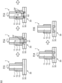
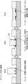
- FIG. 2 is a diagram showing a part of a process using a friction stir spot welding method according to an embodiment of the present disclosure.
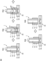
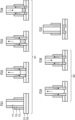
- FIG. 3 is a diagram showing a part of a process using a friction stir spot welding method according to an embodiment of the present disclosure.
- FIG. 4 is a diagram showing a process chart of a friction stir spot welding method according to an embodiment of the present disclosure.
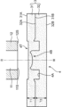
- FIG. 5 is a schematic cross-sectional view for explaining a joint portion of a joint body.
- FIG. 6 is a schematic cross-sectional view showing the distribution of the coating film when no anchor is formed at the joint or when the anchor is small.
- FIG. 1 is a schematic diagram showing a configuration of a friction stir spot welding apparatus according to an embodiment of the present disclosure.
- FIG. 2 is a diagram showing a part of a process using a friction stir spot welding method according to an embodiment of the present disclosure
- FIG. 7 is a schematic cross-sectional view showing the distribution of a coating film when an anchor is formed at a joint.
- FIG. 8 is a diagram showing a process using the friction stir spot welding method according to a modified embodiment of the present disclosure.
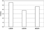
- FIG. 9 is a graph showing the tensile shear strength in the examples and comparative examples of the present disclosure.
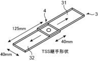
- FIG. 10 is a schematic perspective view showing how the tensile shear strength shown in FIG. 9 is measured.
- FIG. 11 is a cross-sectional photograph of a joint of a comparative example related to the present disclosure.
- FIG. 12 is an enlarged cross-sectional photograph of a part of FIG.
- FIG. 13 is a cross-sectional photograph of a joint in an embodiment of the present disclosure.
- FIG. 14 is an enlarged cross-sectional photograph of a part of FIG.
- FIG. 15 is a cross-sectional photograph of a joint of a comparative example related to the present disclosure.
- FIG. 16 is an enlarged photograph of the bottom surface of an aluminum pillar at a joint in a comparative example related to the present disclosure.
- FIG. 17 is an enlarged cross-sectional photograph of the bottom of the aluminum pillar in FIG.
- FIG. 18 is a cross-sectional photograph of a joint in an embodiment of the present disclosure.
- FIG. 19 is an enlarged photograph of the bottom surface of an aluminum pillar at a joint in an embodiment of the present disclosure.
- FIG. 20 is an enlarged cross-sectional photograph showing an interface between the first member and the second member in FIG. FIG.
- FIG. 21 is a schematic diagram for explaining the position of the bonding interface caused by the shoulder.
- FIG. 22 is a schematic diagram for explaining the position of the bonding interface caused by the shoulder.
- FIG. 23 is a schematic diagram for explaining the position of the bonding interface caused by the shoulder.
- FIG. 24 is a graph showing the transition of the press-in amount of the shoulder during friction stir spot welding.
- FIG. 25 is a graph showing the cross tensile strength in the examples and comparative examples of the present disclosure.
- FIG. 26 is a cross-sectional photograph of a joint in a reference example of the present disclosure.
- FIG. 27 is an enlarged cross-sectional photograph of a part of FIG.
- FIG. 28 is a graph showing the transition of the press-in amount of the shoulder during friction stir spot welding.
- FIG. 29 is a cross-sectional photograph of a joint in an embodiment of the present disclosure.
- FIG. 30 is an enlarged cross-sectional photograph of a portion of FIG.
- FIG. 31 is an
- the friction stir spot welding method according to the present disclosure can be applied to the manufacture of various joined bodies formed by overlapping and spot-joining two or more structural materials, such as metal plates, frames, exterior materials, or columnar materials.
- the joints manufactured become components of structures such as aircraft, railway cars, or automobiles.
- FIG. 1 is a schematic diagram showing a configuration of a friction stir spot welding apparatus M according to an embodiment of the present disclosure.
- the friction stir spot welding device M joins an upper plate 31 and a lower plate 32 by softening them with frictional heat.
- the friction stir spot welding device M includes a tool 1 for friction stir spot welding, a tool drive unit 2 that drives the tool 1 to rotate and raise and lower, and a controller C that controls the operation of the tool drive unit 2. Note that although the directions “up” and “down” are indicated in FIG. 1 for ease of explanation, this is not intended to limit the actual direction in which the tool 1 is used.
- the tool 1 is supported by a tool fixing portion.
- the tool fixing portion can be, for example, the tip of an articulated robot.
- a backup 15 is disposed facing the lower end surface of the tool 1.
- At least two metal members to be joined are disposed between the tool 1 and the backup 15.
- FIG. 1 shows an example in which an overlapping portion 30, in which a part of an upper plate 31 made of a flat plate and a part of a lower plate 32 also made of a flat plate overlap in the vertical direction, is disposed between the tool 1 and the backup 15.
- the tool 1 corresponds to the joining tool of this disclosure.
- the tool 1 includes a pin 11 having a central axis extending along a predetermined axial direction, a shoulder 12, a clamp 13, and a spring 14.
- the pin 11 is formed in a cylindrical shape and is arranged so that its central axis extends in the vertical direction.
- the pin 11 can rotate about the central axis as the rotation axis R, and can move up and down along the rotation axis R, that is, move forward and backward.
- the rotation axis R is aligned with the point joining position W at the overlapping portion 30.
- the tool 1 is a double-acting tool in which the pin 11 and shoulder 12 move independently.
- the shoulder 12 is a cylindrical member with a hollow portion into which the pin 11 is inserted.
- the axis of the shoulder 12 is coaxial with the axis of the pin 11, which is the rotation axis R.
- the shoulder 12 rotates around the rotation axis R and moves up and down along the rotation axis R, that is, moves forward and backward.
- the shoulder 12 and the pin 11 inserted in the hollow portion both rotate around the axis of rotation R, while moving relatively in the direction of the axis of rotation R.
- the pin 11 and shoulder 12 can not only rise and fall simultaneously along the axis of rotation R, but can also move independently, with one descending and the other ascending.
- the clamp 13 is a cylindrical member with a hollow portion into which the shoulder 12 is inserted.
- the axis of the clamp 13 is also coaxial with the rotation axis R.
- the clamp 13 does not rotate around its axis, but moves up and down along the rotation axis R, that is, moves forward and backward.
- the clamp 13 serves to surround the outer periphery of the pin 11 or the shoulder 12 when they perform friction stirring.
- the enclosure with the clamp 13 prevents the friction stirring material from scattering, and allows the friction stirring point joint to be finished smoothly.
- the spring 14 is attached to the upper end side of the clamp 13 and biases the clamp 13 downward, toward the overlapping portion 30.
- the clamp 13 is attached to the tool fixing portion via the spring 14.
- the backup 15 has a support surface 15A that supports the underside of the overlapping portion 30, which is the object to be joined.
- the backup 15 is a backing member that supports the overlapping portion 30 when the pin 11 or shoulder 12 is pressed into the overlapping portion 30.
- the clamp 13 biased by the spring 14 presses the overlapping portion 30 against the backup 15.
- the tool driving unit 2 includes a rotation driving unit 21 and a lifting driving unit 22.
- the rotation driving unit 21 includes a motor, a driving gear, etc., and drives the pin 11 and the shoulder 12 to rotate around the rotation axis R.
- the rotation driving unit 21 corresponds to the rotation mechanism of the present disclosure that rotates the tool 1.
- the lifting driving unit 22 is a mechanism that moves the pin 11, the shoulder 12, and the clamp 13 forward and backward, i.e., raises and lowers them, along the rotation axis R.
- the lifting driving unit 22 drives the pin 11 so as to press the pin 11 into the overlapping portion 30 and retract it from the overlapping portion 30.
- the lifting driving unit 22 also moves the shoulder 12 forward and backward along the rotation axis R, causing the shoulder 12 to press into and retract from the overlapping portion 30.
- the lifting drive unit 22 corresponds to the movement mechanism of the present disclosure, which can move the pin 11 and the shoulder 12 independently in the axial direction along which the pin 11 extends.
- the lifting drive unit 22 also moves the clamp 13 toward the overlapping portion 30, pressing the overlapping portion 30 against the backup 15. At this time, the biasing force of the spring 14 acts.
- the device is composed of three shafts: a first lifting shaft that drives the pin 11, the shoulder 12, and the clamp 13 together, a second lifting shaft that drives the pin 11 independently, and a central rotating shaft.
- the controller C is made up of a microcomputer or the like, and controls the operation of each part of the tool driving unit 2 by executing a predetermined control program. Specifically, the controller C controls the rotation driving unit 21 to cause the pin 11 and shoulder 12 to perform the required rotational operation. The controller C also controls the lifting driving unit 22 to cause the pin 11, shoulder 12, and clamp 13 to perform the required forward and backward movement operation.
- the controller C corresponds to the control unit in this disclosure, and sets the rotation, movement amount, movement position, pressure force, etc. of each member described below.
- the upper plate 31 is made of metal, and has an upper plate surface 31A and an upper plate back surface 31B as shown in FIG. 1.
- the upper plate surface 31A is the surface of the upper plate 31, and corresponds to the upper surface of the upper plate 31 in FIG. 1.
- the upper plate back surface 31B is the back surface of the upper plate 31, and corresponds to the lower surface of the upper plate 31 in FIG. 1.
- the upper plate 31 corresponds to the first member of the present disclosure.
- the upper plate surface 31A corresponds to the first surface of the present disclosure
- the upper plate back surface 31B corresponds to the first back surface of the present disclosure.
- the upper plate 31 is an aluminum alloy (aluminum).
- the upper plate 31 may be a wrought material or a cast metal.
- the upper plate 31 is also subjected to electrochemical coating. That is, a coating film is formed on the upper plate surface 31A and the upper plate back surface 31B of the upper plate 31. In other embodiments, the upper plate 31 may be subjected to chemical conversion treatment or the like.
- the aluminum in the present disclosure includes an aluminum alloy.
- the lower plate 32 is made of metal, and has a lower plate surface 32A and a lower plate back surface 32B as shown in FIG. 1.
- the lower plate surface 32A is the surface of the lower plate 32, and corresponds to the upper surface of the lower plate 32 in FIG. 1.
- the lower plate back surface 32B is the back surface of the lower plate 32, and corresponds to the lower surface of the lower plate 32 in FIG. 1.
- the lower plate 32 corresponds to the second member of the present disclosure.
- the lower plate surface 32A corresponds to the second surface of the present disclosure
- the lower plate back surface 32B corresponds to the second back surface of the present disclosure.
- the lower plate 32 is high tensile steel (steel). That is, the upper plate 31 and the lower plate 32 are made of different metals.
- the lower plate 32 may be an aluminum alloy, mild steel (steel), or hot stamp steel (steel).
- the lower plate 32 may also be subjected to non-plating, zinc plating, Al-Si plating, chemical conversion treatment, electroplating, etc.
- an adhesive or a sealant may be interposed between the upper plate 31 and the lower plate 32.
- examples of combinations in which the upper plate 31 and the lower plate 32 are made of different materials include, in the order of the upper plate 31 and the lower plate 32, the following: (Example 1) Al and Fe, (Example 2) resin and Fe, (Example 3) Al and Mg, (Example 4) resin and Mg, (Example 5) resin and Al.
- the hardness of the lower plate 32 is higher than the hardness of the upper plate 31, so the anchor 4B described below can be stably formed.
- a method of using the tool 1 exemplified in this embodiment i.e., a friction stir spot welding method
- the method of using the friction stir spot welding apparatus M is roughly classified into a pin-first process in which the pin 11 of the tool 1 is pressed into the overlapping portion 30 of the joining members first, and a shoulder-first process in which the shoulder 12 is pressed into the overlapping portion 30 of the joining members first.
- the shoulder-first process is adopted in this embodiment.
- FIGS. 2 and 3 are diagrams showing a part of the process using the friction stir spot welding method with the shoulder-first process. Note that the process in FIG. 3 is carried out after the process in FIG. 2.
- FIG. 4 is a diagram showing a process chart of the friction stir spot welding method according to this embodiment.
- FIGS. 2 to 4 show the process of friction stir spot welding the overlapping portion 30 of the upper plate 31 and the lower plate 32.
- an overlapping portion 30 is formed by an upper plate 31 and a lower plate 32.
- the overlapping portion 30 at least a portion of the lower plate surface 32A abuts against the upper plate back surface 31B, and the upper plate 31 and the lower plate 32 are arranged so as to overlap.
- the tool 1 is placed at a predetermined position and rotated. Specifically, the tool 1 is placed facing the overlapping portion 30 so that the rotation axis R of the tool 1 is parallel to the overlapping direction of the upper plate 31 and the lower plate 32, that is, the vertical direction.
- the rotation axis R of the tool 1 may be arranged so as to be inclined with respect to the vertical direction.
- the lower end surface of the tool 1 is abutted against the upper plate surface 31A of the upper plate 31 with the rotation axis R aligned with the predetermined point joining position W as shown in FIG. 1.
- the clamp 13 presses the overlapping portion 30 against the backup 15 with the biasing force of the spring 14 in FIG. 1.
- the controller C controls the rotation drive unit 21 in FIG. 1 to rotate the pin 11 and the shoulder 12 at a predetermined number of rotations around the rotation axis R.
- process P11 in FIG. 2 and step S2 in FIG. 4 show the preheating process of the overlapping portion 30.
- a pressing process is performed in which the pin 11 retreats from the overlapping portion 30 and the shoulder 12 is pressed into the overlapping portion 30.
- the controller C controls the lifting drive unit 22 to lower the shoulder 12 as shown in process P12 in FIG. 2 while maintaining the rotation of the tool 1, and presses it into the overlapping portion 30, while controlling the lifting drive unit 22 to raise the pin 11, that is, to retreat.
- the clamp 13 is immobile.
- the shoulder 12 is pressed into the overlapping portion 30 from the upper plate surface 31A to the first pressing position deeper than the lower plate surface 32A.
- the lower plate surface 32A at this time corresponds to the surface of the second member in this disclosure, and is the upper metal surface of the lower plate 32. Even if the lower plate 32 has a coating film, the surface of the second member refers to the surface of the metal part.
- the above pressing operation also agitates the material in the pressing region of the shoulder 12, as shown by the arrow b1 in FIG. 2, and the overflow material OF that overflows from the overlapping portion 30 due to the pressing is released into the hollow space in the shoulder 12 created by the retraction of the pin 11.
- the base portion of the anchor 4B in FIG. 5, which will be described in detail later, is formed.
- a pressure force along the axial direction that is, a pressing pressure force
- a pressure force is applied to the entire pin 11, shoulder 12, and clamp 13.
- a pressure force is applied to the clamp 13 to press the clamp 13 against the backup 15.
- the pressure force with which the tool 1 is pressed against the joint 3 corresponds to the pressure force obtained by subtracting the clamp pressure force from the pressing pressure force.
- the controller C controls the lift drive unit 22 to move the shoulder 12 away from the first press-in position, and controls the lift drive unit 22 to lower the pin 11 so that it enters the overlapping portion 30.
- This process shows a backfilling process of the overflow material OF.
- the controller C controls the lift drive unit 22 to raise the shoulder 12, while controlling the lift drive unit 22 to lower the pin 11.
- the overflow material OF that has escaped into the hollow space is backfilled into the press-in area of the shoulder 12, as shown by the arrow b2 in FIG. 2.
- a smoothing process is performed to smooth the overlapping portion 30.
- the controller C controls the lifting drive unit 22 to rotate the lower end surface of the pin 11 and the lower end surface of the shoulder 12 while positioning them slightly lower than the upper plate surface 31A of the upper plate 31, thereby smoothing the point joint portion.
- the tool 1 is moved away from the overlapping portion 30.
- process P21 of FIG. 3 the lower end surface of the tool 1 is again brought into contact with the upper plate surface 31A of the upper plate 31.
- the controller C controls the rotation drive unit 21 of FIG. 1 to rotate the pin 11 and shoulder 12 at a predetermined number of rotations around the rotation axis R.
- This rotation preheats the area in the overlapping portion 30 where the pin 11 and shoulder 12 are in contact by friction, as shown in step S7 of FIG. 4. That is, process P21 of FIG. 3, like process P11 of FIG. 2, shows a preheating process for the overlapping portion 30.
- the pin 11 is retracted from the overlapping portion 30, and the pressing process is performed again to press the shoulder 12 into the overlapping portion 30.
- This process is generally similar to process P12 of FIG. 2.
- the shoulder 12 is pressed into the overlapping portion 30 from the upper plate surface 31A until it reaches a predetermined second pressing position.
- the controller C controls the lift drive unit 22 to move the shoulder 12 away from the second press-fit position, and also controls the lift drive unit 22 to lower the pin 11 so that it enters the overlapping portion 30.
- This process is generally similar to process P13 in FIG. 2.
- the smoothing process is performed again to smooth the overlapping portion 30.
- the controller C controls the lifting drive unit 22 to rotate the lower end surface of the pin 11 and the lower end surface of the shoulder 12 while positioning them slightly lower than the upper plate surface 31A of the upper plate 31, and smooth the spot joint portion.
- the indent 4T in FIG. 5 which will be described in detail later, is formed. Note that the indent 4T does not necessarily have to be formed.
- the tool 1 is separated from the overlapping portion 30.
- the stir welded portion 4 in FIG. 1 is formed, in which the upper plate 31 and the lower plate 32 are joined.
- the stir welded portion 4 corresponds to the joint in this disclosure.
- Fig. 5 is a schematic cross-sectional view for explaining the stir welded portion 4 of the welded body 3 formed by the above-mentioned friction stir spot welding method.
- the stir welded portion 4 has a weld bottom surface 4A, an anchor 4B, and an indent 4T. Note that Fig. 5 shows thicknesses T1 and T2 of the upper plate 31 and the lower plate 32.
- the joint bottom surface 4A is the joint interface between the upper plate 31 and the lower plate 32, which is generated at a position deeper than the lower plate surface 32A with respect to the upper plate surface 31A when pressed against the shoulder 12.
- the joint bottom surface 4A When viewed along the rotation axis R, the joint bottom surface 4A has a ring shape corresponding to the shoulder lower surface portion 12S of the shoulder 12. Note that the ring shape is not limited to two perfect circles, and may be an irregular shape depending on the conditions of the friction stir spot welding. In other words, the joint bottom surface 4A has a substantially ring shape in a plan view.
- the anchor 4B is a raised portion in which a part of the lower plate 32 is raised to a position higher than the lower plate surface 32A with respect to the joint bottom surface 4A on the radially inner side.
- the anchor 4B is formed when the overflow material OF that overflows from the overlapping portion 30 into the hollow space of the shoulder 12 during the press-in process is crushed at its upper end by the pin 11 during the backfilling process. As shown in Figure 5, the outer edge of the tip of the anchor 4B tends to become claw-shaped. The higher the amount by which the shoulder 12 is pressed into the lower plate 32, the greater the height of the raised anchor 4B.
- the indent 4T is disposed opposite the joint bottom surface 4A and anchor 4B in the overlapping direction of the upper plate 31 and the lower plate 32, i.e., in the vertical direction, and corresponds to a recessed portion in the upper plate surface 31A of the upper plate 31.
- the indent 4T can be actively formed in the smoothing process by rotating the lower end surface of the pin 11 and the lower end surface of the shoulder 12 while positioning them lower than the upper plate surface 31A of the upper plate 31, but in the smoothing process, the lower end surface of the pin 11 and the lower end surface of the shoulder 12 may be positioned flush with the upper plate surface 31A of the upper plate 31. Also, as described above, the indent 4T does not have to be formed.
- the friction stir spot welding method according to this embodiment, two welding processes are performed for one joint.
- the first welding process Q1 the upper plate 31 and the lower plate 32 are joined so that the coating film is unevenly distributed at a specific position within the friction stir welding portion 4.
- the series of processes in FIG. 2 described above corresponds to this first welding process Q1.
- the second welding process Q2 the coating film unevenly distributed at the specific position is dispersed.
- the series of processes in FIG. 3 described above corresponds to this second welding process Q2.
- the discloser further found that in this method of dispersing the coating film, the formation of anchor 4B in FIG. 5 is particularly effective.
- Figure 6 is a schematic cross-sectional view showing the distribution of the coating when no anchor is formed at the stir welded portion 4 or when the anchor is small.
- Figure 7 is a schematic cross-sectional view showing the distribution of the coating when an anchor is formed at the stir welded portion 4.
- Figures 6 and 7 correspond to processes P12, P13, and P14 in Figure 2, respectively. Note that the pin 11 and shoulder 12 are not shown.
- the upper plate 31 is made of aluminum and the lower plate 32 is made of steel, and a coating is formed on the surface of the upper plate 31, i.e., the upper plate surface 31A and the upper plate back surface 31B in Figures 1 and 5.
- the coating is made of cationic electrocoating formed, for example, to prevent corrosion.
- the pressure acting near the interface between the upper plate 31 and the lower plate 32 is relatively small, so the coating film tends to aggregate at the interface and in the center.
- the overflowing material OF spreads out the coating film, and as a result, the coating film returns to its original position, i.e., near the interface. As a result, even at the end of process P14, the coating film is distributed in a similar area.
- the anchor 4B can be formed stably.
- the pressing force of the shoulder 12 acts strongly near the interface between the upper plate 31 and the lower plate 32, so the coating film tends to aggregate inside the anchor 4B.
- the overflowing material OF flows below the shoulder 12.
- the coating film spread by the overflowing material OF is distributed so as to spread from the upper end of the anchor to the shoulder path, i.e., the passing area of the shoulder 12, as in process P14 in Figure 7.
- process P12 the shoulder 12 is pressed into the lower plate 32 to a position deeper than the lower plate surface 32A, so that the interface between the upper plate 31 and the lower plate 32 at the shoulder portion on the outside of the anchor is in a state of good adhesion without being affected by the coating.
- the coating can be stirred and efficiently dispersed as the shoulder 12 rotates when the shoulder 12 is pressed into the second press-in position.
- the coating is prevented from concentrating in one part of the stirred joint 4, and the joint 3 can be prevented from breaking starting from this coating part.
- FIG. 8 is a diagram showing a part of a process using a friction stir spot welding method according to a modified embodiment of the present disclosure.
- the clamp 13 of the tool 1 is separated from the upper plate 31 between the first welding process Q1 and the second welding process Q2, but the present disclosure is not limited to this.
- a series of processes are performed without the clamp 13 of the tool 1 being separated from the upper plate 31.
- processes P31 to P34 in FIG. 8 correspond to the first welding process Q1.
- the preheating step is performed, and in processes P32 and P33, the shoulder 12 is pressed in to the first press-in position while the pin 11 is raised.
- process P34 the pin 11 is lowered and the shoulder 12 is raised. Thereafter, the second welding process Q2 is continuously performed. Specifically, in process P35, the shoulder 12 is pressed in to the second press-in position while the pin 11 is raised. Then, in process P36, the pin 11 is lowered while the shoulder 12 is raised, and the backfilling step is performed. Then, in process P37, the leveling step is performed, and the tool 1 is separated from the upper plate 31.
- the coating film can be unevenly distributed at a specific position in the first joining process Q1, and the coating film can be dispersed in the second joining process Q2. This prevents the coating film from concentrating in a part of the stir joining portion 4, and prevents the joined body 3 from breaking from this coating part.
- the tool 1 does not move away from the upper plate 31 between the first joining process Q1 and the second joining process Q2, so the rotation axis R of the tool 1 does not shift between the two joining processes, and as described below, it is possible to prevent the shoulder 12 from contacting the anchor 4B. Therefore, the strength of the joined body 3 after joining can be stably maintained. Note that even in the joining method according to the above embodiment, the same strength can be maintained by accurately reproducing the position of the tool 1 between the first joining process Q1 and the second joining process Q2.
- an anchor 4B is formed on the inside of the shoulder 12 to unevenly distribute the coating at a specific position, and then in the second joining process Q2, the coating is dispersed, so that the members having the coating can be stably joined and their strength can be maintained. Therefore, after joining the upper plate 31 and the lower plate 32, there is no need to form a coating for corrosion prevention on the joined body 3, and multiple members can be joined using materials on which a coating has already been formed. In addition, as described in detail below, it is possible to improve the strength of the stir welded portion 4 by about 1.3 times compared to the case where members having a coating are joined by only one conventional joining process.
- the anchor 4B can be stably formed and the coating film can be raised above the bonding interface between the upper plate 31 and the lower plate 32.
- the coating film can be stably dispersed in the second bonding process Q2.
- the anchor 4B can be formed more stably.
- the anchor 4B it is desirable to form the anchor 4B so that it satisfies the relationship HA/tu ⁇ 2.7(%), where HA is the height of the anchor 4B based on the interface between the upper plate 31 and the lower plate 32 before joining, and tu is the surface position of the upper plate 31 before joining. It is even more desirable to form the anchor 4B so that it satisfies the relationship HA/tu ⁇ 5.3(%).
- anchor 4B It is also desirable to form the anchor 4B so that its height is 0.16 mm or more, based on the interface between the upper plate 31 and the lower plate 32 before joining.
- the top of the anchor 4B means the point with the maximum vertical distance from the surface of the lower plate 32, in other words, the highest point of the anchor 4B.
- the second press-fit position may be set deeper or shallower than the first press-fit position. However, by setting the second press-fit position shallower than the first press-fit position, the shoulder 12 is less likely to come into contact with the material of the lower plate 32 in the second joining process Q2, making it easier to maintain the joined state of the upper plate 31 and the lower plate 32 joined in the first joining process Q1.
- the hardness of the lower plate 32 is set to be higher than that of the upper plate 31, so that a part of the lower plate 32 is more likely to protrude in the first joining process Q1, and the anchor 4B can be stably formed.
- the coating film can be stably held in a specific position by the anchor 4B, and the dispersion effect in the second joining process Q2 can be improved.
- the point joining position W is prevented from shifting between the two joining processes, making it easier to prevent deformation of the formed anchor 4B.
- Fig. 9 is a graph showing the tensile shear strength TSS in the examples and comparative examples of the present disclosure.
- Fig. 10 is a schematic perspective view showing the state of measuring the tensile shear strength shown in Fig. 9.
- Comparative Example 1 in Fig. 9 corresponds to a case where a coating film is not formed on either the upper plate 31 or the lower plate 32, and where the plates are joined by a conventional one-time joining process.
- Comparative Example 2 corresponds to a case where a coating film is formed only on the upper plate 31, and where the plates are joined by a conventional one-time joining process.
- Example 1 corresponds to a case where a coating film is formed only on the upper plate 31, and where the plates are joined by two joining processes as shown in Figs. 2 and 3.
- TSS indicates the load at which the stir weld 4 breaks when the upper plate 31 and the lower plate 32 of the joint 3 after the stir weld 4 is formed are pulled in opposite directions parallel to the upper plate surface 31A.
- TSS value the higher the TSS value, the higher the tensile shear strength.
- Comparative Example 1 where no coating was formed, had a TSS of 5.6 (kN), while Comparative Example 2, where a coating was formed on the upper plate 31, had a TSS of 3.8 (kN), resulting in a decrease in joint strength. It is believed that this phenomenon occurs because unevenly distributed coating at the stir welded portion 4 makes it easy for fractures to occur.
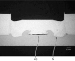
- Figure 11 is a cross-sectional photograph of the stir welded portion 4 of Comparative Example 2.
- Figure 12 is an enlarged cross-sectional photograph of region N in Figure 11. As shown in Figure 12, in Comparative Example 2, the coating remains unevenly in layers around the anchor 4B, resulting in the above-mentioned decrease in strength.
- Example 2 In contrast, in Example 1, although a coating is formed, it is possible to ensure a TSS of 4.6 (kN) as shown in FIG. 9, making it possible to improve the joining strength compared to Comparative Example 2.
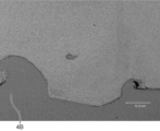
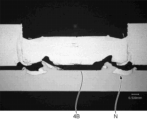
- FIG. 13 is a cross-sectional photograph of the stir welded portion 4 in Example 1.
- FIG. 14 is an enlarged cross-sectional photograph of region N in FIG. 13. As shown in FIG. 14, in Example 2, no coating was found to be biased around the anchor 4B, and it can be seen that the coating is suitably distributed by the shoulder 12 in the second joining process.
- the first press-in position of the shoulder 12 was set at a position shallower than the upper plate back surface 31B of the upper plate 31, and the experiment was performed under conditions in which the anchor 4B was not intentionally formed.
- Figure 15 is a cross-sectional photograph of the stir welded portion 4 of the comparative example.
- Figure 16 is an enlarged photograph of the bottom surface of the aluminum pillar in the stir welded portion 4 of the comparative example.
- Figure 17 is an enlarged cross-sectional photograph of the bottom N of the aluminum pillar in Figure 15.
- the aluminum pillar refers to the cylindrical region located below the pin 11 and inside the shoulder 12 when the process is interrupted.
- the paint film remained widely on the steel interface side of the aluminum pillar as explained above using Figure 6.
- the interface side portion of the aluminum pillar was recessed inward as shown in Figure 17, and the paint film remained inside it.
- Figure 18 is a cross-sectional photograph of the joint of an example of the present disclosure.
- Figure 19 is an enlarged photograph of the bottom surface of the aluminum column at the joint of an example of the present disclosure.
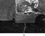
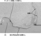
- Figure 20 is an enlarged cross-sectional photograph of the interface N between the upper plate 31 and lower plate 32 of Figure 18.
- the coating film was mainly distributed inside the anchor 4B, as explained above using Figure 7.
- the presence of the anchor 4B makes it possible to prevent the coating film from spreading too far outward beyond the anchor 4B.
- this anchor 4B not much coating film is present near the interface between the upper plate 31 and the lower plate 32 on the outside of the anchor 4B, so it was confirmed that, as shown at the bonding interface CA in Figure 20, the bonding between the aluminum of the upper plate 31 and the steel of the lower plate 32 can be favorably improved even under conditions that include the coating film.
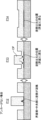
- FIG. 21 is a schematic diagram for explaining the joint interface position by the shoulder 12.
- the position of the upper plate surface 31A of the upper plate 31 is defined as the upper plate position tu
- the height of the anchor 4B i.e., the position of the tip of the anchor 4B
- the first press-fit position of the shoulder 12 in the first joining process Q1 is defined as the first pass joint interface position HI.
- the above values are expressed as zero for the position of the base material interface, which is the original interface between the upper plate back surface 31B of the upper plate 31 and the lower plate surface 32A of the lower plate 32, and the upper plate 31 side is expressed as + and the lower plate 32 side is expressed as minus.
- the thickness T1 of the upper plate 31 in FIG. 5 i.e., the upper plate position tu in FIG. 21 is 3.0 mm
- the thickness T2 of the lower plate 32 in FIG. 5 is 1.6 mm.
- the thickness of the coating of the upper plate 31 is 20 ⁇ m.
- the outer diameter of the shoulder 12 is 8 mm
- the outer diameter of the pin 11 is 5 mm.
- the upper plate position tu corresponds to the surface of the upper plate 31, that is, the upper metal surface of the upper plate 31.
- Table 1 shows the dispersion effect of the coating based on each experimental condition and cross-sectional observation of the stir welded part 4.
- Example 2 was performed under the conditions of the first pass joint interface position HI -0.09 mm, and anchor height HA +0.08 mm. As a result, the ratio of anchor height HA to upper plate position tu was 2.7%, and although there was a small amount of paint remaining on the outside of anchor 4B, the results showed that there was no problem with the strength in practical use, so the paint dispersion effect was rated as ⁇ .
- Example 3 was performed under the conditions of the first pass joint interface position HI -0.16 mm and anchor height HA +0.26 mm. As a result, the ratio of anchor height HA to upper plate position tu was 8.7%, and no residual paint film was found near the outer joint interface of anchor 4B, so it was rated as good.
- Example 4 was performed under the conditions of the first pass joint interface position HI -0.20 mm and anchor height HA +0.42 mm. As a result, the ratio of anchor height HA to upper plate position tu was 14.0%, and no residual paint film was found near the outer joint interface of anchor 4B, so it was rated as good.
- Example 5 the first pass was performed with the joint interface position HI-0.30 mm and anchor height HA+0.72 mm. As a result, the ratio of anchor height HA to upper plate position tu was 24.0%, and no residual paint film was found near the joint interface on the outside of anchor 4B, so it was rated as good.
- the first press-in position of the shoulder 12 for the first time is desirable to set at a position deeper than the lower plate surface 32A of the lower plate 32.
- a more stable effect can be obtained by setting the first press-in position at a position 0.09 mm or more deeper than the lower plate surface 32A of the lower plate 32.
- the first press-fit position be set at a position deeper than the position 0.09 mm deep from the lower plate surface 32A of the lower plate 32. It is even more desirable that the first press-fit position be set at a position 0.16 mm or deeper than the lower plate surface 32A of the lower plate 32.
- the anchor height HA is set to 0.08 mm or more, more preferable that it is set to greater than 0.08 mm, and even more preferable that it is set to 0.26 mm or more.
- the ratio of the anchor height HA to the upper plate position tu is set to 2.7% or more, more preferably to be set to greater than 2.7%, and even more preferably to be set to 8.7% or more.
- the present inventors also conducted the same experiment as above with coating thicknesses of 8 ⁇ m and 30 ⁇ m, and confirmed that similar results were obtained.
- Fig. 22 is a schematic diagram for explaining the joining interface position by the shoulder 12.
- the second press-fit position of the shoulder 12 in the second joining process Q2 is defined as the second pass joining interface position HI'.
- the magnitude of the anchor height HA is an actual measurement value, and HI' is calculated based on a drive command signal to the controller C.
- Table 2 shows the results of the dispersion effect of the coating film based on each experimental condition and cross-sectional observation of the stir welded portion 4.
- Table 2 compares Example 3, Example 4, and Example 5 in Table 1 based on the second pressing position of the shoulder 12 in the second joining process Q2.
- the method for evaluating the dispersion effect of the coating film is the same as that in Table 1.
- the second press-in position of the shoulder 12 in the second joining process Q2 is set to a position 0.25 mm deeper than the tip of the anchor 4B.
- the second press-in position of the shoulder 12 in the second joining process Q2 is set to a position 0.40 mm deeper than the tip of the anchor 4B.
- the second press-in position of the shoulder 12 in the second joining process Q2 is set to a position 0.41 mm deeper than the tip of the anchor 4B.
- the coating dispersion effect can be favorably obtained. That is, as shown diagrammatically in FIG. 22, it is desirable to set the second press-in position to a position deeper than the tip of the anchor 4B, above the interface between the upper plate 31 and the lower plate 32, in order to favorably disperse the coating film that has floated around the outer periphery of the tip of the anchor 4B.
- FIG. 23 is a schematic diagram for explaining the joint interface position by the shoulder 12.
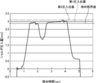
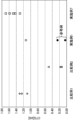
- FIG. 24 is a graph showing the transition of the press-in amount of the shoulder during friction stir spot welding.
- Tables 1 and 2 the experiment was performed under the condition that the second press-in position is set shallower than the first press-in position, but in this experiment, as shown in FIG. 23, the experiment was performed under the condition that the second press-in position is set deeper than the first press-in position.
- Table 3 shows the experimental conditions and the dispersion effect of the coating film based on the cross-sectional observation of the stir welded portion 4.
- Example 6 the first pass joint interface position HI corresponding to the first press-in position is set to -0.12 mm, and the second pass joint interface position HI' corresponding to the second press-in position is set to -0.21 mm.
- the clamp 13 is maintained in contact with the upper plate 31 during welding.
- the tool 1 approaches the upper plate 31, and a preheating process is carried out from about 0.5 seconds to about 1 second. Thereafter, the shoulder 12 is pressed into the upper plate 31, and reaches the interface between the upper plate 31 and the lower plate 32 at about 1.3 seconds. Furthermore, at about 1.8 seconds, the shoulder 12 reaches the first press-in position, and then retreats to about 1.8 mm of shoulder press-in amount so as to move away from the lower plate 32. Thereafter, the shoulder 12 is pressed in again so as to approach the interface between the upper plate 31 and the lower plate 32, and at about 3.8 seconds, it is pressed in to a second press-in position deeper than the first press-in position.
- the shoulder 12 separates from the interface between the upper plate 31 and the lower plate 32, the smoothing process is performed when the shoulder is pressed in at approximately 0.6 mm, and after the indent 4T is formed, the tool 1 separates from the upper plate 31.
- ⁇ About the continuous two-step bonding process> 25 is a graph showing CTS (Cross Tension Strength) in the examples and comparative examples of the present disclosure.
- CTS Cross Tension Strength
- the upper plate 31 and the lower plate 32 are overlapped in a cross shape in a plan view, and the stir weld 4 is formed at the intersection.
- the CTS shown on the vertical axis of FIG. 25 corresponds to the load at which fracture occurs when attempting to peel the upper plate 31 and the lower plate 32 apart from each other.
- the present inventor intentionally caused a position shift of this point joining position W and evaluated the change in the CTS of the joined body 3.
- Figure 25 shows the CTS measurement results for each of the following examples: Comparative Example 1, which does not have a coating and does not perform the second joining process; Comparative Example 2, which has a coating and does not perform the second joining process; Example 1, which has a coating and performs the first joining process Q1 and the second joining process Q2 separately; and Example 7, which performs the first joining process Q1 and the second joining process Q2 continuously without separating the clamp 13 from the upper plate 31 as in the modified embodiment described above.
- the data indicated by white circles corresponds to Example 1
- the data indicated by black circles corresponds to a reference example in which the point joining position W of the second joining process is intentionally shifted under the conditions of Example 1.
- Comparative Example 2 which has a coating, has a lower CTS than Comparative Example 1, which does not have a coating.
- Examples 1 and 7 which perform the first bonding process Q1 and the second bonding process Q2, it was confirmed that the CTS was equal to or higher than that of Comparative Example 1, even under conditions in which a coating was present.
- the reference example in which the point bonding position W was intentionally shifted it was confirmed that the CTS was lower than that of Example 1.
- FIG. 26 is a cross-sectional photograph of the stir welded portion 4 of the reference example of the present disclosure after fracture.
- FIG. 27 is an enlarged cross-sectional photograph of the region N of FIG. 26.
- the upper plate 31 is made of an Al-Si casting with a thickness of 3.0 mm, and the coating film formed by electrochemical deposition has a thickness of 20 ⁇ m.
- the lower plate 32 is a high-tensile steel plate with a thickness of 1.6 mm, for example, a 780 MPa-class GA-plated steel plate.
- Figure 28 is a graph showing the transition of the amount of pressing in of the shoulder 12 during friction stir spot welding in this experiment.
- Table 5 shows the amount of pressing in of the shoulder 12 corresponding to the end of each welding time in Figure 28.
- the amount of pressing is expressed as zero for the surface of the upper plate 31 and plus for the lower plate 32 side.
- “1" corresponds to the preheating process
- "2" to pressing in of the shoulder 12 into the upper plate 31
- "4" to the backfilling process "5" to re-pressing the shoulder 12 to disperse the coating
- "6” to re-backfilling and leveling.
- FIG. 29 is a cross-sectional photograph of the stir welded portion 4 after completion of the joining process of Example 7 of the present disclosure.
- FIG. 30 is an enlarged cross-sectional photograph of the region N1 in FIG. 29, and FIG. 31 is an enlarged cross-sectional photograph of the region N2 in FIG. 29.
- FIG. 31 virtually illustrates a part of the shoulder 12.
- FIG. 29 and FIG. 30 in this experiment, no contact marks of the shoulder 12 with the anchor 4B were confirmed, and it was confirmed that the coating film was sufficiently dispersed near the bonding interface of the upper plate 31 and the lower plate 32.
- FIG. 25 for the bonded body 3 bonded under the conditions of Example 7
- fracture occurred along the interface between the aluminum and the steel, as in the case without the coating film, and no remaining coating film was confirmed on the fracture surface.
- control may be performed so that the shoulder 12 is pressed again inside the shoulder 12 without completely detaching the shoulder 12 from the upper plate 31.
- Plate thickness of the upper plate 31 and the lower plate 32 0.5 mm or more and 5 mm or less, more preferably 1 mm or more and 3 mm or less
- Rotation speed of the tool 500 rpm or more and 4000 rpm or less, more preferably 1500 rpm or more and 2500 rpm or less
- the coating film is described as being formed on the upper plate 31, but the coating film may be formed on at least one of the upper plate 31 and the lower plate 32.
- the friction stir spot joining method is a friction stir spot joining method in which a first member and a second member, at least one of which has a coating formed thereon, are dissimilar materials and are joined by softening them with frictional heat.
- the joining method includes preparing a friction stir spot joining device having a pin and a cylindrical shoulder including a hollow portion into which the pin is inserted; forming an overlapping portion where the first member and the second member overlap, and arranging the pin and the shoulder facing the overlapping portion; retracting the pin from the overlapping portion and pressing the shoulder into a predetermined first press-in position of the overlapping portion to form an anchor in which the second member protrudes inside the shoulder, distributing the coating film at a specific position, and joining the first member and the second member; retracting the shoulder from the first press-in position while moving the pin closer to the overlapping portion; retracting the shoulder from the second press-in position while moving the pin closer to the overlapping portion to disperse the coating film that is unevenly distributed at the specific position; and retracting the shoulder from the second press-in position while moving the pin closer to the overlapping portion.
- the coating is unevenly distributed at a specific position in the first joining process, and then the coating is dispersed in the second joining process, so that the members having the coating can be stably joined and their strength can be maintained. Therefore, after joining the first and second members, the need to form a coating for corrosion prevention on the joined body is reduced, and multiple members can be joined using materials on which a coating has already been formed. In addition, it is possible to improve the strength of the joint by about 1.3 times compared to when members having a coating are joined by only one joining process. In this way, according to this method, it is possible to provide a friction stir spot joining method that can join multiple workpieces having a coating formed on at least one side while preventing a decrease in the joint strength.
- the friction stir spot welding method according to the second aspect of the present disclosure further comprises, in the friction stir spot welding method according to the first aspect described above, setting the first press-in position at a position deeper than the surface of the second member.
- the friction stir spot welding method according to the third aspect of the present disclosure is the friction stir spot welding method according to the first or second aspect described above, further comprising forming the anchor so as to satisfy the relationship HA/tu ⁇ 2.7(%), where HA is the height of the anchor and tu is the position of the surface of the first member based on the interface between the first member and the second member before joining.
- the anchor height is consistently maintained, allowing the coating to be dispersed stably.
- the friction stir spot welding method according to the fourth aspect of the present disclosure further comprises forming the anchor so as to satisfy the relationship HA/tu ⁇ 5.3(%) in the friction stir spot welding method according to the third aspect described above.
- the height of the anchor can be more stably secured, allowing the coating film to be dispersed more stably.
- the friction stir spot welding method according to the fifth aspect of the present disclosure further comprises forming the anchor so that the height of the anchor is 0.16 mm or more based on the interface between the first member and the second member before joining, in the friction stir spot welding method according to the first to fourth aspects described above.
- the anchor height is consistently maintained, allowing the coating to be dispersed stably.
- the friction stir spot welding method according to the sixth aspect of the present disclosure further comprises, in the friction stir spot welding method according to the second aspect described above, setting the first press-in position at a position 0.09 mm or more deeper than the surface of the second member.
- This method allows the anchor to be formed more stably and the coating film to be stably raised above the interface between the first and second components.
- the friction stir spot welding method according to the seventh aspect of the present disclosure is the friction stir spot welding method according to any one of the first to sixth aspects described above, further comprising setting the second press-in position at a position deeper than the top of the anchor.
- the friction stir spot welding method according to the eighth aspect of the present disclosure further comprises, in the friction stir spot welding method according to the seventh aspect described above, setting the second press-in position at a position shallower than the first press-in position.
- the shoulder is less likely to come into contact with the material of the second component, making it easier to maintain the joined state of the first and second components joined in the first joining process.
- the friction stir spot welding method according to a ninth aspect of the present disclosure is the friction stir spot welding method according to any one of the first to eighth aspects described above, further comprising setting the hardness of the second member higher than the hardness of the first member.
- the friction stir spot welding method according to the tenth aspect of the present disclosure is the friction stir spot welding method according to the ninth aspect described above, further comprising the first member being aluminum and the second member being steel.
- the friction stir spot welding method according to an eleventh aspect of the present disclosure is the friction stir spot welding method according to the first to ninth aspects above, further comprising the friction stir spot welding device that is prepared further having a cylindrical clamp including a hollow portion into which the shoulder is inserted, and continuing to bias the first member by the clamp at least from the time when the shoulder is pressed into the first press-in position until the time when the shoulder is pressed into the second press-in position.
- This method prevents the point joining position from shifting between the two joining processes, making it easier to prevent deformation of the formed anchor.
- the friction stir spot joining method is a friction stir spot joining method in which a first member and a second member, at least one of which has a coating film formed thereon, which are dissimilar materials, are softened by frictional heat and joined together.
- the joining method includes preparing a friction stir spot joining device having a pin and a cylindrical shoulder including a hollow portion into which the pin is inserted; forming an overlapping portion where the first member and the second member overlap, and arranging the pin and the shoulder facing the overlapping portion; retracting the pin from the overlapping portion while pressing the shoulder into a predetermined first press-in position of the overlapping portion to form an anchor in which the second member protrudes inside the shoulder, thereby joining the first member and the second member; retracting the shoulder from the first press-in position while moving the pin closer to the overlapping portion; pressing the shoulder into a predetermined second press-in position of the overlapping portion while moving the pin closer to the overlapping portion; retracting the shoulder from the second press-in position while moving the pin closer to the overlapping portion; and setting the first press-in position to a position deeper than the surface of the second member.
- this method it is possible to stably join members having a coating film and maintain their strength. Therefore, after joining the first and second members, the need to form a coating film for corrosion prevention on the joined body is reduced, and multiple members can be joined using materials on which a coating film has been formed in advance. In addition, it is possible to improve the strength of the joint by about 1.3 times compared to when members having a coating film are joined by only one joining process. In particular, by setting the first press-in position at a position deeper than the surface of the second member, it is possible to stably form an anchor and raise the coating film above the interface between the first and second members. As a result, it is possible to stably disperse the coating film in the second joining process. In this way, according to this method, it is possible to provide a friction stir spot joining method that can join multiple workpieces having a coating film formed on at least one side while preventing a decrease in the joining strength.
- a friction stir spot welding device is a friction stir spot welding device capable of joining a first member and a second member, at least one of which is a dissimilar material, by softening them with frictional heat.
- the friction stir spot welding device includes a joining tool having a pin and a cylindrical shoulder including a hollow portion into which the pin is inserted, a rotation mechanism capable of rotating the joining tool, a movement mechanism capable of independently moving the pin and the shoulder in a direction in which the pin extends, and a control unit that controls the rotation mechanism and the movement mechanism to join the first member and the second member with the pin and the shoulder disposed opposite the overlapping portion where the first member and the second member overlap.
- the control unit controls the rotation mechanism and the movement mechanism to retract the pin from the overlapping portion while pressing the shoulder into a first predetermined press-fit position of the overlapping portion, thereby forming an anchor in which the second member protrudes inside the shoulder, distributing the coating film at a specific position and joining the first member and the second member, retracting the shoulder from the first press-fit position while moving the pin closer to the overlapping portion, and then retracting the pin from the overlapping portion while pressing the shoulder into a second predetermined press-fit position of the overlapping portion, thereby dispersing the coating film at the specific position, and retracting the shoulder from the second press-fit position while moving the pin closer to the overlapping portion.
- the coating is unevenly distributed at a specific position in the first joining process, and then the coating is dispersed in the second joining process, making it possible to stably join members having a coating and maintain their strength.
- This reduces the need to form a coating to prevent corrosion on the joined body after joining the first and second members, and makes it possible to join multiple members using materials on which a coating has already been formed.
- it is possible to improve the strength of the joint by about 1.3 times compared to joining members having a coating in only one joining process.
- it is possible to provide a friction stir spot joining device that can join multiple workpieces having a coating formed on at least one side while preventing a decrease in the joint strength.
- the friction stir spot welding apparatus is the friction stir spot welding apparatus according to the thirteenth aspect described above, in which the control unit controls the movement mechanism to set the first press-in position to a position deeper than the surface of the second member.
- the friction stir spot welding device is the friction stir spot welding device according to the thirteenth or fourteenth aspect described above, in which the control unit controls the movement mechanism to set the second press-in position to a position deeper than the top of the anchor.
- the friction stir spot welding apparatus is the friction stir spot welding apparatus according to the fifteenth aspect described above, in which the control unit controls the movement mechanism to set the second press-in position to a position shallower than the first press-in position.
- the friction stir spot welding apparatus is the friction stir spot welding apparatus according to any one of the thirteenth to sixteenth aspects above, wherein the welding tool further has a cylindrical clamp including a hollow portion into which the shoulder is inserted, the movement mechanism is capable of moving the clamp in the direction in which the pin extends, and the control unit controls the movement mechanism to continue to bias the first member by the clamp at least from the time when the shoulder is pressed into the first press-in position until the time when the shoulder is pressed into the second press-in position.
- This configuration prevents the point joining position from shifting between the two joining processes, making it easier to prevent deformation of the formed anchor.
Landscapes
- Engineering & Computer Science (AREA)
- Mechanical Engineering (AREA)
- Pressure Welding/Diffusion-Bonding (AREA)
Abstract
Description
図1は、本開示の一実施形態に係る摩擦攪拌点接合装置Mの構成を示す模式図である。
続いて、本実施形態で例示しているツール1の使用方法、すなわち、摩擦攪拌点接合方法について説明する。摩擦攪拌点接合装置Mの使用方法としては、大略的に、ツール1のピン11を先行して接合部材の重なり部30へ圧入させるピン先行プロセスと、ショルダ12を先行して接合部材の重なり部30へ圧入させるショルダ先行プロセスとがある。このうち、本実施形態では、ショルダ先行プロセスが採用される。
図5は、上記のような摩擦攪拌点接合方法によって形成された接合体3の攪拌接合部4を説明するための模式的な断面図である。攪拌接合部4は、接合底面4Aと、アンカー4Bと、インデント4Tとを有する。なお、図5では、上板31および下板32の厚さT1、T2が示されている。
前述のように、本実施形態では、一つの接合部に対して、図2のプロセスP11からP15までの工程が行われたのち、図3のプロセスP21からP25までの工程が行われる。従来、一つの接合部に対して、図2のプロセスP11からP15までの工程に類似した工程のみが行われていたが、本開示の開示者は、このような摩擦攪拌点接合方法における問題点を新たに知見するに至った。具体的に、上板31および下板32のうちの少なくとも一方に塗膜が形成されている場合、上記のような従来の摩擦攪拌点接合方法では、接合部の内部に残存した塗膜に起因して接合強度が大きく低下するという問題があった。そして、前記開示者は、接合部の内部において塗膜を好適に分散させ、接合強度の低下を抑止することが可能な新たな摩擦攪拌点接合方法を知見するに至った。
図8は、本開示の変形実施形態に係る摩擦攪拌点接合方法を用いたプロセスの一部を示す図である。上記の実施形態では、図2、図3に示すように、1回目の接合プロセスQ1と2回目の接合プロセスQ2との間でツール1のクランプ13が上板31から離間する態様にて説明したが、本開示はこれに限定されるものではない。本変形実施形態では、ツール1のクランプ13が上板31から離れることなく、一連のプロセスが実行される。具体的に、図8のプロセスP31からP34は、1回目の接合プロセスQ1に相当する。プロセスP31では前記予熱工程が実行され、プロセスP32、P33において、ピン11が上昇しながらショルダ12が第1圧入位置まで圧入される。その後、プロセスP34において、ピン11が下降しショルダ12が上昇する。その後、2回目の接合プロセスQ2が連続して実行される。具体的に、プロセスP35において、ピン11が上昇しながらショルダ12が第2圧入位置まで圧入される。その後、プロセスP36において、ピン11が下降しながらショルダ12が上昇し、前記埋め戻し工程が実行される。その後、プロセスP37において、前記ならし工程が行われたのち、ツール1が上板31から離間する。
図9は、本開示の実施例および比較例における引張せん断強さTSS(Tensile Shear Strength)を示すグラフである。図10は、図9に示す引張せん断強さを測定する様子を示す模式的な斜視図である。図9の比較例1は、上板31および下板32のいずれにも塗膜が形成されていない場合であって、従来の1回の接合プロセスによって接合した場合に相当する。比較例2は、上板31のみに塗膜が形成され、従来の1回の接合プロセスによって接合した場合に相当する。実施例1は、上板31のみに塗膜が形成され、図2、図3のように2つの接合プロセスによって接合した場合に相当する。
次に、接合プロセスにおけるアンカー4Bの有無によって、塗膜がどのように分布しているかを確認する実験を比較例および実施例として行った。本実験では、ストップアクションと称される手法を用いて、ショルダ12を第1圧入位置まで圧入したのちに接合プロセスを中断し、攪拌接合部4の各断面を切断評価した。なお、本実験では、ショルダ12の外径が9mm、ピン11の外径が6mmに設定されている。
次に、1回目の接合プロセスQ1におけるショルダ12の第1圧入位置を変化させた場合の塗膜分散効果を確認した実験結果について説明する。図21は、ショルダ12による接合界面位置を説明するための模式図である。図21において、上板31の上板表面31Aの位置を上板位置tu、アンカー4Bの高さ、すなわちアンカー4Bの先端の位置をアンカー高さHA、1回目の接合プロセスQ1におけるショルダ12の第1圧入位置を1パス目接合界面位置HIと定義する。なお、上記の各値は上板31の上板裏面31Bと下板32の下板表面32Aとの元々の界面である母材部界面の位置をゼロとし、上板31側を+、下板32側をマイナスで表している。本実験では、図5の上板31の厚さT1、すなわち図21の上板位置tuが3.0mm、図5の下板32の厚さT2は1.6mmである。また、上板31の塗膜の厚さは20μmである。また、ショルダ12の外径は8mm、ピン11の外径は5mmである。なお、上板位置tuは、上板31の表面、すなわち、上板31の上部金属表面に相当する。

次に、2回目の接合プロセスQ2におけるショルダ12の第2圧入位置を変化させた場合の塗膜分散効果を確認した結果について説明する。図22は、ショルダ12による接合界面位置を説明するための模式図である。図22では、図21と比較して、2回目の接合プロセスQ2におけるショルダ12の第2圧入位置を2パス目接合界面位置HI’と定義している。なお、アンカー高さHAの大きさは実測値であり、HI’はコントローラCに対する駆動指令信号に基づいて算出している。
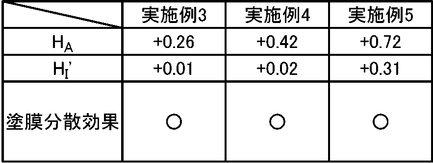
図23は、ショルダ12による接合界面位置を説明するための模式図である。図24は、摩擦攪拌点接合時のショルダの圧入量の推移を示すグラフである。表1、表2の例では、第2圧入位置を第1圧入位置よりも浅く設定する条件にて実験を行ったが、本実験では、図23に示すように、第2圧入位置を第1圧入位置よりも深い位置に設定する条件で実験を行った。表3に、実験条件および攪拌接合部4の断面観察に基づく塗膜の分散効果結果を示す。当該実験に基づく実施例6では、第1圧入位置に相当する1パス目接合界面位置HIが-0.12mmに設定され、第2圧入位置に相当する2パス目接合界面位置HI’が-0.21mmに設定される。なお、本実験では、前述の変形実施形態のように、接合中、クランプ13が上板31に当接した状態が維持される。
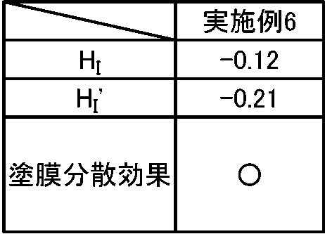

図25は、本開示の実施例および比較例におけるCTS(Cross Tension Strength:十字引張強さ)を示すグラフである。この十字引張強さの評価では、上板31および下板32を平面視で十字状に重ね合わせ、その交差部に攪拌接合部4を形成する。図25の縦軸に示されるCTSは、上記の上板31および下板32を上下に引き剥がそうとする際に、破断が発生する荷重に相当する。

・上板31および下板32の板厚:0.5mm以上、5mm以下、より望ましくは、1mm以上、3mm以下・ツールの回転速度:500rpm以上、4000rpm以下、より望ましくは、1500rpm以上、2500rpm以下
以上説明した具体的実施形態には、以下の構成を有する開示が含まれている。
Claims (17)
- 少なくとも一方に塗膜が形成された第1部材および第2部材であって異材の関係にある第1部材および第2部材を摩擦熱で軟化させて接合する摩擦攪拌点接合方法であって、
ピンと前記ピンが内挿される中空部を含む円筒状のショルダとを有する摩擦攪拌点接合装置を準備することと、
前記第1部材と前記第2部材とが重なり合う重なり部を形成するとともに、前記ピンおよび前記ショルダを前記重なり部に対向して配置することと、
前記ピンを前記重なり部から退避させつつ前記ショルダを前記重なり部の所定の第1圧入位置まで圧入することで前記ショルダの内側に前記第2部材が隆起したアンカーを形成し、前記塗膜を特定位置に偏在させて、前記第1部材と前記第2部材とを接合することと、
前記ピンを前記重なり部に近づけながら前記ショルダを前記第1圧入位置から退避させることと、
前記ピンを前記重なり部から退避させつつ前記ショルダを前記重なり部の所定の第2圧入位置まで圧入することで、前記特定位置に偏在した前記塗膜を分散させることと、
前記ピンを前記重なり部に近づけながら前記ショルダを前記第2圧入位置から退避させることと、
を備える、摩擦攪拌点接合方法。 - 前記第1圧入位置を、前記第2部材の表面よりも深い位置に設定することを更に備える、請求項1に記載の摩擦攪拌点接合方法。
- 接合前の前記第1部材と前記第2部材との界面を基準とした、前記アンカーの高さをHA、前記第1部材の表面の位置をtuとすると、HA/tu≧2.7(%)の関係を満たすように、前記アンカーを形成することを更に備える、請求項1に記載の摩擦攪拌点接合方法。
- HA/tu≧5.3(%)の関係を満たすように、前記アンカーを形成することを更に備える、請求項3に記載の摩擦攪拌点接合方法。
- 接合前の前記第1部材と前記第2部材との界面を基準とした、前記アンカーの高さが0.16mm以上となるように、前記アンカーを形成することを更に備える、請求項1に記載の摩擦攪拌点接合方法。
- 前記第1圧入位置を、前記第2部材の表面よりも0.09mm以上深い位置に設定することを更に備える、請求項2に記載の摩擦攪拌点接合方法。
- 前記アンカーの頂部よりも深い位置に前記第2圧入位置を設定することを更に備える、請求項1乃至6の何れか1項に記載の摩擦攪拌点接合方法。
- 前記第2圧入位置を前記第1圧入位置よりも浅い位置に設定することを更に備える、請求項7に記載の摩擦攪拌点接合方法。
- 前記第1部材の硬度よりも前記第2部材の硬度を高く設定することを更に備える、請求項1の記載の摩擦攪拌点接合方法。
- 前記第1部材はアルミニウムであり、前記第2部材は鋼であることを更に備える、請求項9に記載の摩擦攪拌点接合方法。
- 準備される前記摩擦攪拌点接合装置が、前記ショルダが内挿される中空部を含む円筒状のクランプを更に有し、
少なくとも、前記ショルダの前記第1圧入位置への圧入から前記ショルダの前記第2圧入位置への圧入までの間、前記クランプによって前記第1部材を付勢しつづけることを更に備える、請求項1に記載の摩擦攪拌点接合方法。 - 少なくとも一方に塗膜が形成された第1部材および第2部材であって異材の関係にある第1部材および第2部材を摩擦熱で軟化させて接合する摩擦攪拌点接合方法であって、
ピンと前記ピンが内挿される中空部を含む円筒状のショルダとを有する摩擦攪拌点接合装置を準備することと、
前記第1部材と前記第2部材とが重なり合う重なり部を形成するとともに、前記ピンおよび前記ショルダを前記重なり部に対向して配置することと、
前記ピンを前記重なり部から退避させつつ前記ショルダを前記重なり部の所定の第1圧入位置まで圧入することで前記ショルダの内側に前記第2部材が隆起したアンカーを形成し、前記第1部材と前記第2部材とを接合することと、
前記ピンを前記重なり部に近づけながら前記ショルダを前記第1圧入位置から退避させることと、
前記ピンを前記重なり部から退避させつつ前記ショルダを前記重なり部の所定の第2圧入位置まで圧入することと、
前記ピンを前記重なり部に近づけながら前記ショルダを前記第2圧入位置から退避させることと、
前記第1圧入位置を、前記第2部材の表面よりも深い位置に設定することと、
を備える、摩擦攪拌点接合方法。 - 少なくとも一方に塗膜が形成された第1部材および第2部材であって異材の関係にある第1部材および第2部材を摩擦熱で軟化させて接合することが可能な摩擦攪拌点接合装置であって、
ピンと前記ピンが内挿される中空部を含む円筒状のショルダとを有する接合ツールと、
前記接合ツールを回転させることが可能な回転機構と、
前記ピンおよび前記ショルダを前記ピンが延びる方向に独立して移動させることが可能な移動機構と、
前記ピンおよび前記ショルダが前記第1部材と前記第2部材とが重なり合う重なり部に対向して配置された状態で、前記回転機構および前記移動機構を制御して、前記第1部材と前記第2部材とを接合する制御部と、
を備え、
前記制御部は、前記回転機構および前記移動機構を制御して、
前記ピンを前記重なり部から退避させつつ前記ショルダを前記重なり部の所定の第1圧入位置まで圧入することで前記ショルダの内側に前記第2部材が隆起したアンカーを形成し、前記塗膜を特定位置に偏在させて、前記第1部材と前記第2部材とを接合し、
前記ピンを前記重なり部に近づけながら前記ショルダを前記第1圧入位置から退避させたのち、前記ピンを前記重なり部から退避させつつ前記ショルダを前記重なり部の所定の第2圧入位置まで圧入することで、前記特定位置に偏在した前記塗膜を分散させ、
前記ピンを前記重なり部に近づけながら前記ショルダを前記第2圧入位置から退避させる、摩擦攪拌点接合装置。 - 前記制御部は、前記移動機構を制御して、前記第1圧入位置が、前記第2部材の表面よりも深い位置に設定する、請求項13に記載の摩擦攪拌点接合装置。
- 前記制御部は、前記移動機構を制御して、前記第2圧入位置を、前記アンカーの頂部よりも深い位置に設定する、請求項13または14に記載の摩擦攪拌点接合装置。
- 前記制御部は、前記移動機構を制御して、前記第2圧入位置を、前記第1圧入位置よりも浅い位置に設定する、請求項15に記載の摩擦攪拌点接合装置。
- 前記接合ツールは、前記ショルダが内挿される中空部を含む円筒状のクランプを更に有し、
前記移動機構は、前記ピンが延びる方向において前記クランプを動かすことが可能であり、
前記制御部は、前記移動機構を制御して、少なくとも、前記ショルダの前記第1圧入位置への圧入から前記ショルダの前記第2圧入位置への圧入までの間、前記クランプによって前記第1部材を付勢しつづける、請求項13に記載の摩擦攪拌点接合装置。
Priority Applications (3)
| Application Number | Priority Date | Filing Date | Title |
|---|---|---|---|
| DE112024002770.9T DE112024002770T5 (de) | 2023-06-29 | 2024-06-13 | Reibrührpunktschweißverfahren und Reibrührpunktschweißvorrichtung |
| JP2025529631A JPWO2025004829A1 (ja) | 2023-06-29 | 2024-06-13 | |
| CN202480042652.3A CN121398924A (zh) | 2023-06-29 | 2024-06-13 | 摩擦搅拌点接合方法及摩擦搅拌点接合装置 |
Applications Claiming Priority (2)
| Application Number | Priority Date | Filing Date | Title |
|---|---|---|---|
| JP2023-107312 | 2023-06-29 | ||
| JP2023107312 | 2023-06-29 |
Publications (1)
| Publication Number | Publication Date |
|---|---|
| WO2025004829A1 true WO2025004829A1 (ja) | 2025-01-02 |
Family
ID=93938768
Family Applications (1)
| Application Number | Title | Priority Date | Filing Date |
|---|---|---|---|
| PCT/JP2024/021518 Ceased WO2025004829A1 (ja) | 2023-06-29 | 2024-06-13 | 摩擦攪拌点接合方法および摩擦攪拌点接合装置 |
Country Status (4)
| Country | Link |
|---|---|
| JP (1) | JPWO2025004829A1 (ja) |
| CN (1) | CN121398924A (ja) |
| DE (1) | DE112024002770T5 (ja) |
| WO (1) | WO2025004829A1 (ja) |
Citations (3)
| Publication number | Priority date | Publication date | Assignee | Title |
|---|---|---|---|---|
| JP2017164788A (ja) * | 2016-03-17 | 2017-09-21 | 川崎重工業株式会社 | 摩擦攪拌点接合方法及び摩擦攪拌点接合装置 |
| WO2019049814A1 (ja) * | 2017-09-05 | 2019-03-14 | 川崎重工業株式会社 | 複動式摩擦攪拌点接合方法及び複動式摩擦攪拌点接合装置 |
| WO2022054905A1 (ja) * | 2020-09-11 | 2022-03-17 | 川崎重工業株式会社 | 摩擦攪拌点接合方法及びこれを用いた接合体 |
-
2024
- 2024-06-13 CN CN202480042652.3A patent/CN121398924A/zh active Pending
- 2024-06-13 WO PCT/JP2024/021518 patent/WO2025004829A1/ja not_active Ceased
- 2024-06-13 DE DE112024002770.9T patent/DE112024002770T5/de active Pending
- 2024-06-13 JP JP2025529631A patent/JPWO2025004829A1/ja active Pending
Patent Citations (3)
| Publication number | Priority date | Publication date | Assignee | Title |
|---|---|---|---|---|
| JP2017164788A (ja) * | 2016-03-17 | 2017-09-21 | 川崎重工業株式会社 | 摩擦攪拌点接合方法及び摩擦攪拌点接合装置 |
| WO2019049814A1 (ja) * | 2017-09-05 | 2019-03-14 | 川崎重工業株式会社 | 複動式摩擦攪拌点接合方法及び複動式摩擦攪拌点接合装置 |
| WO2022054905A1 (ja) * | 2020-09-11 | 2022-03-17 | 川崎重工業株式会社 | 摩擦攪拌点接合方法及びこれを用いた接合体 |
Also Published As
| Publication number | Publication date |
|---|---|
| CN121398924A (zh) | 2026-01-23 |
| JPWO2025004829A1 (ja) | 2025-01-02 |
| DE112024002770T5 (de) | 2026-04-30 |
Similar Documents
| Publication | Publication Date | Title |
|---|---|---|
| CN107520550B (zh) | 用于将铝焊接到钢的多梯级电极焊接面的几何形状 | |
| US8960523B2 (en) | Friction stir welding of dissimilar metals | |
| US11964338B2 (en) | Method for low-temperature joining of metal materials, and joint structure | |
| EP1995015B1 (en) | Method of joining materials | |
| US20090291322A1 (en) | Joined body and process for manufacturing the same | |
| US20100083480A1 (en) | Method of Friction-Assisted Clinching | |
| US11806801B2 (en) | Joining method | |
| DE102013106692B4 (de) | Rührreibschweissverfahren für metallwerkstück | |
| CN113613822B (zh) | 铝材的点焊方法和铝材 | |
| EP4011540B1 (en) | Dissimilar material solid phase bonding method | |
| Sharma et al. | Friction stir spot welding-process and weld properties: a review | |
| JPWO2019182020A1 (ja) | 両面摩擦撹拌接合用回転ツール、両面摩擦撹拌接合装置、及び両面摩擦撹拌接合方法 | |
| JP2005161382A (ja) | 金属部材のスポット接合方法およびその装置。 | |
| CN107186334A (zh) | 用于旋转摩擦冲压的铆钉结构及其铆接钢铝叠层板的方法 | |
| US20070280849A1 (en) | Friction stir welding process and structure | |
| EP1769876B1 (en) | Friction stir spot welding method and apparatus with an holding member having a restriction portion | |
| JP4998027B2 (ja) | 摩擦点接合方法 | |
| JP7173081B2 (ja) | アルミニウム合金板と鋼板の摩擦撹拌接合方法 | |
| CN106994554A (zh) | 用于将包含钢的构件与包含铝的构件相接合的方法 | |
| CN110814507B (zh) | 一种利用液相挤入消除搅拌摩擦焊根部缺陷的方法 | |
| JP2009113077A (ja) | 摩擦点接合方法 | |
| WO2024029498A1 (ja) | 接合体、摩擦攪拌点接合方法および摩擦攪拌点接合装置 | |
| CN121398924A (zh) | 摩擦搅拌点接合方法及摩擦搅拌点接合装置 | |
| WO2025253900A1 (ja) | 摩擦攪拌点接合装置および摩擦攪拌点接合方法 | |
| WO2025075060A1 (ja) | 摩擦攪拌点接合方法および摩擦攪拌点接合装置 |
Legal Events
| Date | Code | Title | Description |
|---|---|---|---|
| 121 | Ep: the epo has been informed by wipo that ep was designated in this application |
Ref document number: 24831694 Country of ref document: EP Kind code of ref document: A1 |
|
| ENP | Entry into the national phase |
Ref document number: 2025529631 Country of ref document: JP Kind code of ref document: A |
|
| WWE | Wipo information: entry into national phase |
Ref document number: 2025529631 Country of ref document: JP |
|
| WWE | Wipo information: entry into national phase |
Ref document number: 112024002770 Country of ref document: DE |
|
| WWP | Wipo information: published in national office |
Ref document number: 112024002770 Country of ref document: DE |