EP1995015B1 - Method of joining materials - Google Patents
Method of joining materials Download PDFInfo
- Publication number
- EP1995015B1 EP1995015B1 EP07736886A EP07736886A EP1995015B1 EP 1995015 B1 EP1995015 B1 EP 1995015B1 EP 07736886 A EP07736886 A EP 07736886A EP 07736886 A EP07736886 A EP 07736886A EP 1995015 B1 EP1995015 B1 EP 1995015B1
- Authority
- EP
- European Patent Office
- Prior art keywords
- joint
- materials
- metal material
- joining
- auxiliary metal
- Prior art date
- Legal status (The legal status is an assumption and is not a legal conclusion. Google has not performed a legal analysis and makes no representation as to the accuracy of the status listed.)
- Expired - Fee Related
Links
Images

Classifications
-
- B—PERFORMING OPERATIONS; TRANSPORTING
- B23—MACHINE TOOLS; METAL-WORKING NOT OTHERWISE PROVIDED FOR
- B23K—SOLDERING OR UNSOLDERING; WELDING; CLADDING OR PLATING BY SOLDERING OR WELDING; CUTTING BY APPLYING HEAT LOCALLY, e.g. FLAME CUTTING; WORKING BY LASER BEAM
- B23K20/00—Non-electric welding by applying impact or other pressure, with or without the application of heat, e.g. cladding or plating
- B23K20/12—Non-electric welding by applying impact or other pressure, with or without the application of heat, e.g. cladding or plating the heat being generated by friction; Friction welding
-
- B—PERFORMING OPERATIONS; TRANSPORTING
- B21—MECHANICAL METAL-WORKING WITHOUT ESSENTIALLY REMOVING MATERIAL; PUNCHING METAL
- B21J—FORGING; HAMMERING; PRESSING METAL; RIVETING; FORGE FURNACES
- B21J15/00—Riveting
- B21J15/02—Riveting procedures
- B21J15/027—Setting rivets by friction heating
-
- B—PERFORMING OPERATIONS; TRANSPORTING
- B21—MECHANICAL METAL-WORKING WITHOUT ESSENTIALLY REMOVING MATERIAL; PUNCHING METAL
- B21J—FORGING; HAMMERING; PRESSING METAL; RIVETING; FORGE FURNACES
- B21J15/00—Riveting
-
- B—PERFORMING OPERATIONS; TRANSPORTING
- B21—MECHANICAL METAL-WORKING WITHOUT ESSENTIALLY REMOVING MATERIAL; PUNCHING METAL
- B21J—FORGING; HAMMERING; PRESSING METAL; RIVETING; FORGE FURNACES
- B21J15/00—Riveting
- B21J15/02—Riveting procedures
-
- B—PERFORMING OPERATIONS; TRANSPORTING
- B23—MACHINE TOOLS; METAL-WORKING NOT OTHERWISE PROVIDED FOR
- B23K—SOLDERING OR UNSOLDERING; WELDING; CLADDING OR PLATING BY SOLDERING OR WELDING; CUTTING BY APPLYING HEAT LOCALLY, e.g. FLAME CUTTING; WORKING BY LASER BEAM
- B23K20/00—Non-electric welding by applying impact or other pressure, with or without the application of heat, e.g. cladding or plating
- B23K20/12—Non-electric welding by applying impact or other pressure, with or without the application of heat, e.g. cladding or plating the heat being generated by friction; Friction welding
- B23K20/122—Non-electric welding by applying impact or other pressure, with or without the application of heat, e.g. cladding or plating the heat being generated by friction; Friction welding using a non-consumable tool, e.g. friction stir welding
- B23K20/1265—Non-butt welded joints, e.g. overlap-joints, T-joints or spot welds
-
- B—PERFORMING OPERATIONS; TRANSPORTING
- B23—MACHINE TOOLS; METAL-WORKING NOT OTHERWISE PROVIDED FOR
- B23K—SOLDERING OR UNSOLDERING; WELDING; CLADDING OR PLATING BY SOLDERING OR WELDING; CUTTING BY APPLYING HEAT LOCALLY, e.g. FLAME CUTTING; WORKING BY LASER BEAM
- B23K20/00—Non-electric welding by applying impact or other pressure, with or without the application of heat, e.g. cladding or plating
- B23K20/12—Non-electric welding by applying impact or other pressure, with or without the application of heat, e.g. cladding or plating the heat being generated by friction; Friction welding
- B23K20/122—Non-electric welding by applying impact or other pressure, with or without the application of heat, e.g. cladding or plating the heat being generated by friction; Friction welding using a non-consumable tool, e.g. friction stir welding
- B23K20/127—Non-electric welding by applying impact or other pressure, with or without the application of heat, e.g. cladding or plating the heat being generated by friction; Friction welding using a non-consumable tool, e.g. friction stir welding friction stir welding involving a mechanical connection
-
- Y—GENERAL TAGGING OF NEW TECHNOLOGICAL DEVELOPMENTS; GENERAL TAGGING OF CROSS-SECTIONAL TECHNOLOGIES SPANNING OVER SEVERAL SECTIONS OF THE IPC; TECHNICAL SUBJECTS COVERED BY FORMER USPC CROSS-REFERENCE ART COLLECTIONS [XRACs] AND DIGESTS
- Y10—TECHNICAL SUBJECTS COVERED BY FORMER USPC
- Y10T—TECHNICAL SUBJECTS COVERED BY FORMER US CLASSIFICATION
- Y10T29/00—Metal working
- Y10T29/49—Method of mechanical manufacture
- Y10T29/49826—Assembling or joining
Definitions
- the present invention relates to methods for joining materials.
- JP 2003-266183 A on the figures 7-12 of which the preamble of claims 1 and 6 is based concerns the provision of enabling a friction stir welding method in which friction stir welding is possible for a hardly plastic flow material and the welding in combination of materials for which welding is usually impossible.
- members to be joined on one end are composed of hardly plastic flow materials, and a first and second recesses that assist the welding are formed on the joining surface.
- An intermediate member which is a member to be joined on the other end is composed of a material that is easily plastic-flowable.
- the probe of the tool is pushed against the intermediate member for friction stirring.
- the material of the intermediate member is subjected to plastic flow along the recesses of the members to be joined, so that the members to be joined on both ends are firmly welded together.
- the invention was made in view of the above and has its object to provide a method for joining materials which is free from projections accompanying a design restriction as well as loosening and dropout, which enables joining of materials widely ranging from thinner sheets to thicker plates while preventing quality defects such as cracks and deformation from occurring and which can conduct joining with excellent recyclability while maintaining excellent workability and working environment.
- a first aspect of the invention is directed to a method for joining materials according to claim 1.
- the mechanical engaging part provided by the auxiliary material tightly fitted into the joint holes with respect to the respective materials brings about anti-dropout and ant-rotation effects, whereby the respective materials are firmly joined together through the auxiliary material.
- the respective materials are joined together through the auxiliary material fitted into the joint holes of the respective materials, which enables joining of the respective materials widely ranging from thinner sheets to thicker plates without unreasonable pressing force and with frictional heat applied to the auxiliary material by the joint tool to soften the auxiliary material, so that quality defects such as cracks and deformation can be prevented from occurring.
- the respective materials are mechanically joined together through the engaging part without intermediate such as adhesive agent, so that the joining is free from aggravated workability and working environment unlike use of adhesive agent and has excellent recyclability since separation is readily performed upon recycling of the materials.
- flanges are formed on axially opposite ends of the auxiliary material to pinchingly hold the respective materials in an overlapped direction may serve as engaging part, at least one of said flanges being formed upon immersion of the joint tool to be completed as engaging part.
- According aspect of the invention is directed to a method for joining materials according to claim 6.
- the holes formed into the respective materials may be have aspot-like shape, the joint tool being aligned with the joint holes so as to conduct spot joining; alternatively, the holes formed into the respective materials may have a slot-like shape , the joint tool being moved longitudinally of the joint holes so as to conduct continuous joining.
- a method for joining materials of the invention as mentioned above can exhibit various excellent effects and advantages. Because of no large projections such as a bolt and a nut being protruded unlike bolt-on fastening, a design restriction can be substantially relieved and there is no fear of loosening and dropout unlike bolt-on fastening. Moreover, joining is enabled for materials widely ranging from thinner sheets to thicker plates while preventing quality defects such as cracks and deformation from occurring. Joining with excellent recyclability can be conducted while maintaining excellent workability and working environment.
- Figs. 1-4 show an embodiment of the invention which exemplifies spot joining of mutually overlapped iron and aluminum materials 1 and 2.
- the materials 1 and 2 are formed with spot-like joint holes 1a and 2a extending through the materials in a direction of their thicknesses, respectively, and are overlapped with their joint holes 1a and 2a being aligned.
- Joint auxiliary material 3 made of aluminum is fitted into the aligned holes 1a and 2a and a backing member 4 is arranged underneath the overlapped materials 1 and 2.
- the backing member 4 has an upper surface formed with a concave 6 which confronts the joint holes 1a and 2a of the materials 1 and 2a and which has plane section greater than the joint holes 1a and 2a.
- a cylindrical joint tool 8 Arranged above the respective materials 1 and 2 and coaxially of the joint holes 1a and 2a is a cylindrical joint tool 8 with a pin 7 on its lower end adapted to be inserted into the joint holes 1a and 2a, the joint tool being supported rotatably and vertically movably by a joining device (not shown).
- the overlapped materials 1 and 2 are joined together by the joint tool 8 which is lowered, while being rotated, to be pressed onto the auxiliary material 3 in the joint holes 1a and 2a as shown in Fig. 2 .
- the joint tool 8 is lowered into the state shown in Fig. 3 where the auxiliary material 3 softened by frictional heat is tightly fitted, due to plastic flow, into the joint holes 1a and 2a to provide a spiral (threaded) ridge 5' fitted with the groove 5, and is fitted with the concave 6 on the backing member 4 to provide a lower end of the auxiliary material 3 with a flange 6' which has plane section greater than the joint holes 1a and 2a, the auxiliary material 3 being projected into a gap between a shoulder 9 of the joint tool 8 around a base end of the pin 7 and an upper surface of the material 1 to provide an upper end of the auxiliary material 3 with a flange 6" which has plane section greater than the joint holes 1a and 2a.
- These ridge 5' and flanges 6' and 6" provide mechanical engaging parts with respect to the respective materials 1 and 2.
- the lower material 2 is of the same kind as the auxiliary material 3, so that when the pin 7 of the joint tool 8 is rotated and immersed into the auxiliary material 3, a boundary between the material 2 and the auxiliary material 3 which are of the same kind is stirred by rotation of the joint tool 8 to provide a friction stir weld or joint 10.
- the joint tool 8 is extracted upward and the ridge 5' and the flanges 6' and 6" and the friction stir weld 10 are allowed to harden.
- the ridge 5' and flanges 6' and 6" provided by the auxiliary material 3 with respect to the respective materials 1 and 2 bring about anti-dropout and anti-rotation effects, whereby the respective materials 1 and 2 are firmly joined together through the auxiliary material 3.
- the friction stir weld or joint 10 formed between the material 2 and the auxiliary material 3 further enhances the firm joining.
- the iron material 1 and the aluminum auxiliary material 3 afforded between the iron material 1 and the aluminum auxiliary material 3 is an effect of diffusion bonding or joint due to diffusion of atoms generated between them since the joint auxiliary material 3 softened in solid phase due to the frictional heat generated is fitted with and pressed on the material 1 in a temperature condition of lower than a melting point.
- the respective materials 1 and 2 are firmly joined together with no large projections such as a bolt and a nut unlike bolt-on fastening, so that there is no design restriction of ensuring occupation space required for such projections.
- the auxiliary material 3 is tightly fitted into the joint holes 1a and 2a, so that there are no fears on loosening and dropout unlike bolt-on fastening.
- the flanges 6' and 6" are slightly protruded out of the upper and lower surfaces of the respective materials 1 and 2.
- the upper and lower surfaces of the materials 1 and 2, respectively may be countersunk to provide concaves contiguous with the joint holes 1a and 2a and having plane sections greater than the joint holes 1a and 2a such that the flanges 6' and 6" are fitted into the upper and lower countersunk concaves, respectively. This makes flat the final contour of the upper and lower surfaces of the materials 1 and 2, respectively.
- the respective materials 1 and 2 are joined together through the auxiliary material 3 fitted into the joint holes 1a and 2a of the respective materials 1 and 2, which enables joining of the respective materials 1 and 2 widely ranging from thinner sheets to thicker plates without unreasonable pressing force and with frictional heat applied to the auxiliary material 3 by the joint tool 8 to soften the auxiliary material, so that quality defects such as cracks and deformation can be prevented from occurring.
- the respective materials 1 and 2 are mechanically joined together through the engaging part without intermediate such as adhesive agent, so that the joining is free from aggravated workability and working environment unlike use of adhesive agent and has excellent recyclability since separation is readily performed upon recycling of the materials.
- design restrictions can be substantially relieved since there are no large projections such as a bolt and a nut unlike bolt-on fastening and fears on loosening and dropout are released unlike bolt-on fastening.
- joining is enabled over wide variety of materials widely ranging from thin sheets to thicker plates while preventing quality defects such as cracks and deformation from occurring. Further, joining can be made with excellent recyclability while maintaining workability and working environment good.
- the spiral groove 5 threaded on the inner periphery of the joint hole 1a; however, the groove 5 is not always limited to that formed spirally.
- a combination of ring- and spline-shaped grooves 5 may attain the anti-dropout and anti-rotation effects without using the flanges 6' and 6".
- the respective materials 1 and 2 and the auxiliary material 3 may be of different kinds so as not to form a friction stir weld or joint 10 between them.
- the flanges 6' and 6" formed on axially opposite ends of the auxiliary material 3 to pinchingly hold the respective materials 1 and 2 in an overlapped direction serves as engaging parts, these flanges 6' and 6" being concurrently formed upon immersion of the joint tool 8; alternatively, as shown in Fig. 5 , the auxiliary material 3 with a flange 6" at its upper end in advance may be employed, only the flange 6" at the lower end being formed by the concave 6 on the backing member 4 upon immersion of the joint tool 8 and completed as engaging part.
- the auxiliary material 3 When the auxiliary material 3 with the flange 6" at its upper end in advance is employed, the auxiliary material 3 may be manually set in the joint holes 1a and 2a before the joining device is installed, so that a device such as a feeder for locating the auxiliary material 3 in the joint holes 1a and 2a becomes unnecessary.
- the above-mentioned embodiment is exemplified with the spot-like joint holes 1a and 2a formed on the materials 1 and 2, the joint tool 8 being aligned with the joining holes 1a and 2a so as to conduct spot joining; alternatively, the joining holes 1a and 2a may be formed in a slot form so as to conduct continuous joining by the joining tool 8 moved longitudinally of the joining holes 1a and 2a.
- a method for joining materials according to the invention is not limited to the above-mentioned embodiment and that various changes and modifications may be made without departing from the scope of the invention as defined by the claims.
- the respective materials are not always different materials.
- the auxiliary material may be preliminarily formed with a guide bore for guiding immersion of a joint tool.
- the sectional configuration of the joint holes are not limited to rectangular as shown; the joint holes with various different sections may be appropriately employed so as to attain greater joint area for the purpose of improving strength.
Description
- The present invention relates to methods for joining materials.
- Recently, in the automobile industry, joining different kinds of materials such as aluminum and iron members which are hardly weldable together has become more and more important since lightweight material such as an aluminum member has been positively utilized from a viewpoint of making a vehicle light in weight for improvement of fuel efficiency. Conventionally, different kinds of materials hardly weldable together have been joined together by means of, for example, bolt-on fastening, joining through mechanical clinch or adhesion through adhesive agent.
- A conventional technology pertinent for joining materials has been disclosed,for example, in
JP2004-136365A
JP 2003-266183 A claims 1 and 6 is based concerns the provision of enabling a friction stir welding method in which friction stir welding is possible for a hardly plastic flow material and the welding in combination of materials for which welding is usually impossible. According toJP 2003-266183 A - However, for example, use of bolt-on fastening brings abut projecting of a bolt and a nut on front-back both sides of the materials to be joined, which leads to a design restriction of ensuring occupation space required for these projections; moreover, in bolt-on fastening, there are fears on loosening and dropout. Use of joining through mechanical clinch may disadvantageously bring about quality defects such as cracks and deformation since the joining is conducted mainly for and between thin sheets and only through pressing with no addition of heat to the materials.
- Use of adhesion through adhesive agent is disadvantageous not only in aggravated workability and working environment but also aggravated recyclability due to difficulty in separation of the adhesive agent from the materials upon recycling.
- The invention was made in view of the above and has its object to provide a method for joining materials which is free from projections accompanying a design restriction as well as loosening and dropout, which enables joining of materials widely ranging from thinner sheets to thicker plates while preventing quality defects such as cracks and deformation from occurring and which can conduct joining with excellent recyclability while maintaining excellent workability and working environment.
- A first aspect of the invention is directed to a method for joining materials according to claim 1.
- Thus, the mechanical engaging part provided by the auxiliary material tightly fitted into the joint holes with respect to the respective materials brings about anti-dropout and ant-rotation effects, whereby the respective materials are firmly joined together through the auxiliary material.
- In this connection, no large projections such as bolt and nut are protruded unlike the bolt-on fastening, so that it is free from design restriction of ensuring occupation space required for such projections. The auxiliary material is tightly fitted into the joint holes, so that there is no fear of loosening and dropout unlike bolt-on fastening.
- The respective materials are joined together through the auxiliary material fitted into the joint holes of the respective materials, which enables joining of the respective materials widely ranging from thinner sheets to thicker plates without unreasonable pressing force and with frictional heat applied to the auxiliary material by the joint tool to soften the auxiliary material, so that quality defects such as cracks and deformation can be prevented from occurring.
- The respective materials are mechanically joined together through the engaging part without intermediate such as adhesive agent, so that the joining is free from aggravated workability and working environment unlike use of adhesive agent and has excellent recyclability since separation is readily performed upon recycling of the materials.
- Advantageously, flanges are formed on axially opposite ends of the auxiliary material to pinchingly hold the respective materials in an overlapped direction may serve as engaging part, at least one of said flanges being formed upon immersion of the joint tool to be completed as engaging part.
- According aspect of the invention is directed to a method for joining materials according to
claim 6. - Advantageously the holes formed into the respective materials may be have aspot-like shape, the joint tool being aligned with the joint holes so as to conduct spot joining; alternatively, the holes formed into the respective materials may have a slot-like shape , the joint tool being moved longitudinally of the joint holes so as to conduct continuous joining.
- A method for joining materials of the invention as mentioned above can exhibit various excellent effects and advantages. Because of no large projections such as a bolt and a nut being protruded unlike bolt-on fastening, a design restriction can be substantially relieved and there is no fear of loosening and dropout unlike bolt-on fastening. Moreover, joining is enabled for materials widely ranging from thinner sheets to thicker plates while preventing quality defects such as cracks and deformation from occurring. Joining with excellent recyclability can be conducted while maintaining excellent workability and working environment.
-
-
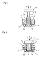
Fig. 1 is a sectional view showing an embodiment of the invention; -
Fig. 2 is a sectional view showing the joint tool ofFig. 1 being lowered while rotated; -
Fig. 3 is a sectional view showing the joint tool being further lowered from the state shown inFig. 2 ; -
Fig. 4 is a sectional view showing the joint tool lifted from the state shown inFig. 3 ; and -
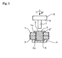
Fig. 5 is a sectional view showing employment of the auxiliary material flanged at its upper end. - Embodiments of the invention will be described in conjunction with the drawings.
-
Figs. 1-4 show an embodiment of the invention which exemplifies spot joining of mutually overlapped iron andaluminum materials 1 and 2. As shown inFig. 1 , thematerials 1 and 2 are formed with spot-like joint holes joint holes auxiliary material 3 made of aluminum is fitted into the alignedholes backing member 4 is arranged underneath the overlappedmaterials 1 and 2. - An inner periphery of the
joint hole 1a of the upper material 1 is threaded to provide aspiral groove 5. Thebacking member 4 has an upper surface formed with a concave 6 which confronts thejoint holes materials 1 and 2a and which has plane section greater than thejoint holes - Arranged above the
respective materials 1 and 2 and coaxially of thejoint holes cylindrical joint tool 8 with apin 7 on its lower end adapted to be inserted into thejoint holes - The overlapped
materials 1 and 2 are joined together by thejoint tool 8 which is lowered, while being rotated, to be pressed onto theauxiliary material 3 in thejoint holes Fig. 2 . This causes theauxiliary material 3 to be softened in solid phase by frictional heat generated between thejoint tool 8 and theauxiliary material 3 so that thepin 7 of thejoint tool 8 is immersed into theauxiliary material 3. - Then, the
joint tool 8 is lowered into the state shown inFig. 3 where theauxiliary material 3 softened by frictional heat is tightly fitted, due to plastic flow, into thejoint holes groove 5, and is fitted with the concave 6 on thebacking member 4 to provide a lower end of theauxiliary material 3 with a flange 6' which has plane section greater than thejoint holes auxiliary material 3 being projected into a gap between ashoulder 9 of thejoint tool 8 around a base end of thepin 7 and an upper surface of the material 1 to provide an upper end of theauxiliary material 3 with aflange 6" which has plane section greater than thejoint holes flanges 6' and 6" provide mechanical engaging parts with respect to therespective materials 1 and 2. - Moreover, especially in this embodiment, the
lower material 2 is of the same kind as theauxiliary material 3, so that when thepin 7 of thejoint tool 8 is rotated and immersed into theauxiliary material 3, a boundary between thematerial 2 and theauxiliary material 3 which are of the same kind is stirred by rotation of thejoint tool 8 to provide a friction stir weld orjoint 10. - Then, as shown in
Fig. 4 , thejoint tool 8 is extracted upward and the ridge 5' and theflanges 6' and 6" and thefriction stir weld 10 are allowed to harden. As a result, the ridge 5' andflanges 6' and 6" provided by theauxiliary material 3 with respect to therespective materials 1 and 2 bring about anti-dropout and anti-rotation effects, whereby therespective materials 1 and 2 are firmly joined together through theauxiliary material 3. Furthermore, the friction stir weld orjoint 10 formed between thematerial 2 and theauxiliary material 3 further enhances the firm joining. - Moreover, afforded between the iron material 1 and the aluminum
auxiliary material 3 is an effect of diffusion bonding or joint due to diffusion of atoms generated between them since the jointauxiliary material 3 softened in solid phase due to the frictional heat generated is fitted with and pressed on the material 1 in a temperature condition of lower than a melting point. - In fact, verification experiments on tensile shear strength conducted by the inventor revealed that good tensile shear strength as many as 8.75 kN is obtained in a case where the upper material 1 is made of SS400 iron with thickness of 5 mm, the
lower material 2 being made of 6000-series aluminum with thickness of 7 mm, the jointauxiliary material 3 being made of 6000-series aluminum which is the same kind with thematerial 2. - In the embodiment, the
respective materials 1 and 2 are firmly joined together with no large projections such as a bolt and a nut unlike bolt-on fastening, so that there is no design restriction of ensuring occupation space required for such projections. Moreover, theauxiliary material 3 is tightly fitted into thejoint holes - In the embodiment illustrated, the
flanges 6' and 6" are slightly protruded out of the upper and lower surfaces of therespective materials 1 and 2. Upon formation of theflanges 6' and 6", the upper and lower surfaces of thematerials 1 and 2, respectively, may be countersunk to provide concaves contiguous with thejoint holes joint holes flanges 6' and 6" are fitted into the upper and lower countersunk concaves, respectively. This makes flat the final contour of the upper and lower surfaces of thematerials 1 and 2, respectively. - Moreover, in the embodiment, the
respective materials 1 and 2 are joined together through theauxiliary material 3 fitted into thejoint holes respective materials 1 and 2, which enables joining of therespective materials 1 and 2 widely ranging from thinner sheets to thicker plates without unreasonable pressing force and with frictional heat applied to theauxiliary material 3 by thejoint tool 8 to soften the auxiliary material, so that quality defects such as cracks and deformation can be prevented from occurring. - The
respective materials 1 and 2 are mechanically joined together through the engaging part without intermediate such as adhesive agent, so that the joining is free from aggravated workability and working environment unlike use of adhesive agent and has excellent recyclability since separation is readily performed upon recycling of the materials. - Thus, according to the above-mentioned embodiment, design restrictions can be substantially relieved since there are no large projections such as a bolt and a nut unlike bolt-on fastening and fears on loosening and dropout are released unlike bolt-on fastening. Moreover, joining is enabled over wide variety of materials widely ranging from thin sheets to thicker plates while preventing quality defects such as cracks and deformation from occurring. Further, joining can be made with excellent recyclability while maintaining workability and working environment good.
- Exemplified in the embodiment illustrated in the above is the
spiral groove 5 threaded on the inner periphery of thejoint hole 1a; however, thegroove 5 is not always limited to that formed spirally. For example, a combination of ring- and spline-shaped grooves 5 (or a combination of spiral and spline-shaped grooves 5) may attain the anti-dropout and anti-rotation effects without using theflanges 6' and 6". Therespective materials 1 and 2 and theauxiliary material 3 may be of different kinds so as not to form a friction stir weld or joint 10 between them. - In the above embodiment, the
flanges 6' and 6" formed on axially opposite ends of theauxiliary material 3 to pinchingly hold therespective materials 1 and 2 in an overlapped direction serves as engaging parts, theseflanges 6' and 6" being concurrently formed upon immersion of thejoint tool 8; alternatively, as shown inFig. 5 , theauxiliary material 3 with aflange 6" at its upper end in advance may be employed, only theflange 6" at the lower end being formed by the concave 6 on thebacking member 4 upon immersion of thejoint tool 8 and completed as engaging part. - When the
auxiliary material 3 with theflange 6" at its upper end in advance is employed, theauxiliary material 3 may be manually set in thejoint holes auxiliary material 3 in thejoint holes - The above-mentioned embodiment is exemplified with the spot-like
joint holes materials 1 and 2, thejoint tool 8 being aligned with the joiningholes holes tool 8 moved longitudinally of the joiningholes - It is to be understood that a method for joining materials according to the invention is not limited to the above-mentioned embodiment and that various changes and modifications may be made without departing from the scope of the invention as defined by the claims. For example, the respective materials are not always different materials. The auxiliary material may be preliminarily formed with a guide bore for guiding immersion of a joint tool. The sectional configuration of the joint holes are not limited to rectangular as shown; the joint holes with various different sections may be appropriately employed so as to attain greater joint area for the purpose of improving strength.
-
- 1
- material
- 1a
- joint hole
- 2
- material
- 2a
- joint hole
- 3
- joint auxiliary material
- 5
- groove
- 5'
- ridge (engaging part)
- 6'
- flange (engaging part)
- 6"
- flange (engaging part)
- 8
- joint tool
- 10
- friction stir weld
Claims (9)
- A method for joining metal materials comprising overlapping the plural metal materials (1, 2) each with a joint hole (1a, 2a) so as to align the joint holes (1a, 2a), fitting joint auxiliary metal material (3) into said aligned joint holes (1a, 2a), rotating and pressing a joint tool (8) from one side in an overlapped direction of said respective metal materials (1, 2) onto the auxiliary metal material (3) to soften said auxiliary metal material (3) in solid phase through frictional heat generated so as to immerse the joint tool (8) into the auxiliary metal material (3), whereby the auxiliary metal material (3) is tightly fitted into the joint holes (1a, 2a) to provide a mechanical engaging part (5', 6', 6") for the respective metal materials (1, 2), extracting said joint tool (8), allowing said engaging part (5', 6', 6") to harden, whereby the respective metal materials (1, 2) are joined together through the auxiliary metal material (3), charaterised in that a ridge (5') formed on the auxiliary metal material (3) fitted with a groove (5) preliminarily formed on an inner side surface of the joint hole (1a, 2a) serves as engaging part.
- A method for joining materials as claimed in claim 1,
wherein flanges (6', 6") formed on axially opposite ends of the auxiliary metal material (3) to pinchingly hold the respective metal materials (1, 2) in an overlapped direction serves as engaging parts, at least one of the flanges (6', 6") being formed upon immersion of the joint tool (8) and completed as engaging part. - A method for joining materials as claimed in any one of claims 1 or 2, wherein at least one of the respective metal materials (1, 2) is of the same kind as the auxiliary metal material (3), a boundary between the very material and the auxiliary metal material (3) being stirred by rotation of the joint tool (8) to provide a friction stir weld or joint (10).
- A method for joining materials as claimed in any one of claims 1 to 3, wherein the joint holes (1a, 2a) formed into said respective materials (1, 2) are spot-like ; and the joint tool (8) is aligned with said joint holes (1a, 2a) to effect spot joining.
- A method for joining materials as claimed in any one of claims 1 to 3, wherein the joint holes (1a, 2a) formed into said respective materials (1, 2) are slot-like ; and the joint tool (8) is moved longitudinally of said joint holes (1a, 2a) to effect continuous joining.
- A method for joining metal materials comprising overlapping the plural metal materials (1, 2) each with a joint hole (1a, 2a) so as to align the joint holes (1a, 2a), fitting joint auxiliary metal material (3) into said aligned joint holes (1a, 2a), rotating and pressing a joint tool (8) from one side in an overlapped direction of said respective metal materials (1, 2) onto the auxiliary metal material (3) to soften said auxiliary metal material (3) in solid phase through frictional heat generated so as to immerse the joint tool (8) into the auxiliary metal material (3), whereby the auxiliary metal material (3) is tightly fitted into the joint holes (1a, 2a) to provide a mechanical engaging part (5', 6', 6") for the respective metal materials (1, 2), extracting said joint tool (8), allowing said engaging part (5', 6', 6") to harden, whereby the respective metal materials (1, 2) are joined together through the auxiliary metal material (3), characterised in that at least one of the respective metal materials (1, 2) is of the same kind as the auxiliary metal material (3), a boundary between the very metal material and the auxiliary metal material (3) being stirred by rotation of the joint tool (8) to provide a friction stir weld or joint (10).
- A method for joining metal materials as claimed in claim 6,
wherein flanges (6', 6") formed on axially opposite ends of the auxiliary metal material (3) to pinchingly hold the respective metal materials (1, 2) in an overlapped direction serves as engaging parts, at least one of the flanges (6', 6") being formed upon immersion of the joint tool (8) and completed as engaging part. - A method for joining materials as claimed in any one of claims 6 or 7, wherein the joint holes (1a, 2a) formed into said respective materials (1, 2) are spot-like ; and the joint tool (8) is aligned with said joint holes (1a, 2a) to effect spot joining.
- A method for joining materials as claimed in any one of claims 6 or 7, wherein the joint holes (1a, 2a) formed into said respective materials (1, 2) are slot-like ; and the joint tool (8) is moved longitudinally of said joint holes (1a, 2a) to effect continuous joining.
Applications Claiming Priority (2)
| Application Number | Priority Date | Filing Date | Title |
|---|---|---|---|
| JP2006072697A JP2007245198A (en) | 2006-03-16 | 2006-03-16 | Material joining method |
| PCT/JP2007/000229 WO2007108208A1 (en) | 2006-03-16 | 2007-03-15 | Method of joining materials |
Publications (3)
| Publication Number | Publication Date |
|---|---|
| EP1995015A1 EP1995015A1 (en) | 2008-11-26 |
| EP1995015A4 EP1995015A4 (en) | 2009-09-09 |
| EP1995015B1 true EP1995015B1 (en) | 2012-12-26 |
Family
ID=38522244
Family Applications (1)
| Application Number | Title | Priority Date | Filing Date |
|---|---|---|---|
| EP07736886A Expired - Fee Related EP1995015B1 (en) | 2006-03-16 | 2007-03-15 | Method of joining materials |
Country Status (6)
| Country | Link |
|---|---|
| US (1) | US20090094813A1 (en) |
| EP (1) | EP1995015B1 (en) |
| JP (1) | JP2007245198A (en) |
| KR (1) | KR20090003290A (en) |
| CN (1) | CN101443152B (en) |
| WO (1) | WO2007108208A1 (en) |
Families Citing this family (12)
| Publication number | Priority date | Publication date | Assignee | Title |
|---|---|---|---|---|
| JP4972417B2 (en) | 2006-12-15 | 2012-07-11 | 日野自動車株式会社 | Member joining method and structure |
| JP4951430B2 (en) * | 2007-07-19 | 2012-06-13 | 光生アルミニューム工業株式会社 | Internal friction welding of pipe members |
| JP5272165B2 (en) * | 2009-03-29 | 2013-08-28 | 独立行政法人国立高等専門学校機構 | Wood material joining method, wood material joining machine, and wood tool |
| CH702672A1 (en) * | 2010-02-10 | 2011-08-15 | Alstom Technology Ltd | Method for joining of blades of turbine with cover band element, involves providing multiple blades arranged on blade carrier, which have rivet shanks at blade tips |
| CN102091861B (en) * | 2010-12-21 | 2013-03-13 | 南京工程学院 | Metal stud welding system combined with friction heat source |
| JP6022402B2 (en) * | 2013-05-22 | 2016-11-09 | 株式会社神戸製鋼所 | Rivet joint structure and manufacturing method thereof |
| JP5590206B2 (en) * | 2013-09-20 | 2014-09-17 | 日本軽金属株式会社 | Manufacturing method of heat transfer plate |
| CN103769521B (en) * | 2014-02-13 | 2016-06-22 | 中国北方车辆研究所 | A kind of turn-over rotation rivetting method improving braking brake pad impact strength |
| DE102016217581A1 (en) * | 2016-09-15 | 2018-03-15 | Schaeffler Technologies AG & Co. KG | Method for forming a rivet head made of a brittle metallic material |
| CN106513555A (en) * | 2016-09-28 | 2017-03-22 | 哈尔滨建成集团有限公司 | Method for riveting by using special riveting fixture |
| CN113508001A (en) * | 2019-04-12 | 2021-10-15 | 日本轻金属株式会社 | Bonding method |
| CN114378421B (en) * | 2020-10-21 | 2023-05-19 | 上海汽车集团股份有限公司 | Method for welding metal pieces with different hardness and welded product of metal pieces with different hardness |
Family Cites Families (24)
| Publication number | Priority date | Publication date | Assignee | Title |
|---|---|---|---|---|
| US2779998A (en) * | 1952-01-30 | 1957-02-05 | Lockheed Aircraft Corp | Method of forming a mechanical and electrical connection |
| US3495321A (en) * | 1965-07-07 | 1970-02-17 | Walker Mfg Co | Method of making a connection |
| US3848389A (en) * | 1969-12-29 | 1974-11-19 | Textron Inc | Bimetal rivets |
| US4087038A (en) * | 1975-12-19 | 1978-05-02 | Harima Sargyo Kabushiki Kaisha | Frictional welding method |
| GB9119022D0 (en) * | 1991-09-05 | 1991-10-23 | Welding Inst | Friction forming |
| JP2827621B2 (en) * | 1991-10-23 | 1998-11-25 | 三菱電機株式会社 | High current substrate and method of manufacturing the same |
| JP4092794B2 (en) * | 1998-11-02 | 2008-05-28 | 日本軽金属株式会社 | Joining method |
| US6230958B1 (en) * | 1999-09-30 | 2001-05-15 | Lockheed Martin Corporation | Friction pull plug welding: dual chamfered plate hole |
| US6769595B2 (en) * | 2000-12-20 | 2004-08-03 | Alcoa Inc. | Friction plunge riveting |
| JP3861719B2 (en) * | 2002-03-12 | 2006-12-20 | 株式会社デンソー | Friction stir welding method |
| JP4199952B2 (en) * | 2002-03-15 | 2008-12-24 | 新明和工業株式会社 | Hollow assembly structure and aircraft rotor blade |
| US6854634B2 (en) * | 2002-05-14 | 2005-02-15 | The Boeing Company | Method of manufacturing rivets having high strength and formability |
| JP2004106037A (en) * | 2002-09-20 | 2004-04-08 | Hitachi Ltd | Method for bonding metal |
| WO2005018866A1 (en) * | 2003-08-22 | 2005-03-03 | Honda Motor Co., Ltd. | Method for friction stir welding, jig therefor member with friction stir-welded portion, and tool for friction stir welding |
| US7398911B2 (en) * | 2003-12-16 | 2008-07-15 | The Boeing Company | Structural assemblies and preforms therefor formed by friction welding |
| US7347641B2 (en) * | 2004-03-31 | 2008-03-25 | The Boeing Company | Methods and systems for joining structures |
| JP2006316964A (en) * | 2005-05-16 | 2006-11-24 | Toyota Motor Corp | Bolt fixing method and bolt fixing structure |
| US7624910B2 (en) * | 2006-04-17 | 2009-12-01 | Lockheed Martin Corporation | Perforated composites for joining of metallic and composite materials |
| JP4886277B2 (en) * | 2005-11-17 | 2012-02-29 | 日野自動車株式会社 | Material joining method |
| JP5094140B2 (en) * | 2006-11-09 | 2012-12-12 | 日野自動車株式会社 | Member joint structure |
| JP4966034B2 (en) * | 2006-11-10 | 2012-07-04 | 日野自動車株式会社 | Member joint structure |
| JP5094141B2 (en) * | 2006-11-10 | 2012-12-12 | 日野自動車株式会社 | Member joint structure |
| JP4972417B2 (en) * | 2006-12-15 | 2012-07-11 | 日野自動車株式会社 | Member joining method and structure |
| JP4591547B2 (en) * | 2008-05-26 | 2010-12-01 | 株式会社豊田中央研究所 | CONNECTED BODY AND METHOD FOR PRODUCING THE SAME |
-
2006
- 2006-03-16 JP JP2006072697A patent/JP2007245198A/en active Pending
-
2007
- 2007-03-15 US US12/282,453 patent/US20090094813A1/en not_active Abandoned
- 2007-03-15 CN CN2007800171291A patent/CN101443152B/en not_active Expired - Fee Related
- 2007-03-15 KR KR1020087023913A patent/KR20090003290A/en not_active Application Discontinuation
- 2007-03-15 EP EP07736886A patent/EP1995015B1/en not_active Expired - Fee Related
- 2007-03-15 WO PCT/JP2007/000229 patent/WO2007108208A1/en active Application Filing
Also Published As
| Publication number | Publication date |
|---|---|
| JP2007245198A (en) | 2007-09-27 |
| WO2007108208A1 (en) | 2007-09-27 |
| US20090094813A1 (en) | 2009-04-16 |
| CN101443152B (en) | 2011-12-14 |
| EP1995015A1 (en) | 2008-11-26 |
| CN101443152A (en) | 2009-05-27 |
| EP1995015A4 (en) | 2009-09-09 |
| KR20090003290A (en) | 2009-01-09 |
Similar Documents
| Publication | Publication Date | Title |
|---|---|---|
| EP1995015B1 (en) | Method of joining materials | |
| US7909229B2 (en) | Method for joining material | |
| US20220059952A1 (en) | Resistance welding fastener, apparatus and methods | |
| US20190134738A1 (en) | Resistance welding fastener, apparatus and methods for joining similar and dissimilar materials | |
| US9012029B2 (en) | Method of bonding panels of dissimilar material and bonded structure | |
| JP7426564B2 (en) | Welding method | |
| US20080067217A1 (en) | Connection of a steel fastening element to a flat aluminium component | |
| JP7012205B2 (en) | Joined structure | |
| JP7015998B2 (en) | Laser welding method | |
| JP5315207B2 (en) | Dissimilar material joined body and dissimilar material resistance spot welding method | |
| US20170166261A1 (en) | Vehicle Body Component | |
| CN112996623A (en) | Welding method for joining dissimilar materials, joining auxiliary member, and welded joint of dissimilar materials | |
| JP4998027B2 (en) | Friction spot welding method | |
| JP2019136748A (en) | Resistance spot welding method | |
| JP4755887B2 (en) | Material joining method | |
| JP2007301578A (en) | Method for joining materials | |
| JP2009082977A (en) | Friction point welding method | |
| JP7131927B2 (en) | Dissimilar Material Joining Method, Joining Auxiliary Member, and Dissimilar Material Joining Joint | |
| Suzuki et al. | Dissimilar metals Joining Process using GMAW has High strength and One side access characteristic, and the Automation robot system | |
| US20140361006A1 (en) | Device for Solid State Joining of Light Metals | |
| JP7475484B2 (en) | Fastening Method | |
| CN107262911B (en) | Method for producing a hybrid connection and device for carrying out said method | |
| JP2003245783A (en) | Spot jointing tool | |
| JP2006095585A (en) | Friction point welding method |
Legal Events
| Date | Code | Title | Description |
|---|---|---|---|
| PUAI | Public reference made under article 153(3) epc to a published international application that has entered the european phase |
Free format text: ORIGINAL CODE: 0009012 |
|
| 17P | Request for examination filed |
Effective date: 20080924 |
|
| AK | Designated contracting states |
Kind code of ref document: A1 Designated state(s): DE GB |
|
| DAX | Request for extension of the european patent (deleted) | ||
| RBV | Designated contracting states (corrected) |
Designated state(s): DE GB |
|
| A4 | Supplementary search report drawn up and despatched |
Effective date: 20090811 |
|
| 17Q | First examination report despatched |
Effective date: 20100127 |
|
| GRAJ | Information related to disapproval of communication of intention to grant by the applicant or resumption of examination proceedings by the epo deleted |
Free format text: ORIGINAL CODE: EPIDOSDIGR1 |
|
| GRAP | Despatch of communication of intention to grant a patent |
Free format text: ORIGINAL CODE: EPIDOSNIGR1 |
|
| GRAP | Despatch of communication of intention to grant a patent |
Free format text: ORIGINAL CODE: EPIDOSNIGR1 |
|
| GRAS | Grant fee paid |
Free format text: ORIGINAL CODE: EPIDOSNIGR3 |
|
| GRAA | (expected) grant |
Free format text: ORIGINAL CODE: 0009210 |
|
| AK | Designated contracting states |
Kind code of ref document: B1 Designated state(s): DE GB |
|
| REG | Reference to a national code |
Ref country code: GB Ref legal event code: FG4D |
|
| REG | Reference to a national code |
Ref country code: DE Ref legal event code: R096 Ref document number: 602007027627 Country of ref document: DE Effective date: 20130228 |
|
| PLBE | No opposition filed within time limit |
Free format text: ORIGINAL CODE: 0009261 |
|
| STAA | Information on the status of an ep patent application or granted ep patent |
Free format text: STATUS: NO OPPOSITION FILED WITHIN TIME LIMIT |
|
| 26N | No opposition filed |
Effective date: 20130927 |
|
| REG | Reference to a national code |
Ref country code: DE Ref legal event code: R097 Ref document number: 602007027627 Country of ref document: DE Effective date: 20130927 |
|
| PGFP | Annual fee paid to national office [announced via postgrant information from national office to epo] |
Ref country code: DE Payment date: 20140222 Year of fee payment: 8 |
|
| PGFP | Annual fee paid to national office [announced via postgrant information from national office to epo] |
Ref country code: GB Payment date: 20140312 Year of fee payment: 8 |
|
| REG | Reference to a national code |
Ref country code: DE Ref legal event code: R119 Ref document number: 602007027627 Country of ref document: DE |
|
| GBPC | Gb: european patent ceased through non-payment of renewal fee |
Effective date: 20150315 |
|
| PG25 | Lapsed in a contracting state [announced via postgrant information from national office to epo] |
Ref country code: GB Free format text: LAPSE BECAUSE OF NON-PAYMENT OF DUE FEES Effective date: 20150315 Ref country code: DE Free format text: LAPSE BECAUSE OF NON-PAYMENT OF DUE FEES Effective date: 20151001 |