WO2025004803A1 - 供試体試験システム、温度調整装置、供試体試験方法、及び、供試体試験用プログラム - Google Patents
供試体試験システム、温度調整装置、供試体試験方法、及び、供試体試験用プログラム Download PDFInfo
- Publication number
- WO2025004803A1 WO2025004803A1 PCT/JP2024/021305 JP2024021305W WO2025004803A1 WO 2025004803 A1 WO2025004803 A1 WO 2025004803A1 JP 2024021305 W JP2024021305 W JP 2024021305W WO 2025004803 A1 WO2025004803 A1 WO 2025004803A1
- Authority
- WO
- WIPO (PCT)
- Prior art keywords
- specimen
- power line
- temperature
- test
- battery
- Prior art date
- Legal status (The legal status is an assumption and is not a legal conclusion. Google has not performed a legal analysis and makes no representation as to the accuracy of the status listed.)
- Ceased
Links
Images

Classifications
-
- G—PHYSICS
- G01—MEASURING; TESTING
- G01M—TESTING STATIC OR DYNAMIC BALANCE OF MACHINES OR STRUCTURES; TESTING OF STRUCTURES OR APPARATUS, NOT OTHERWISE PROVIDED FOR
- G01M17/00—Testing of vehicles
- G01M17/007—Wheeled or endless-tracked vehicles
-
- G—PHYSICS
- G01—MEASURING; TESTING
- G01R—MEASURING ELECTRIC VARIABLES; MEASURING MAGNETIC VARIABLES
- G01R31/00—Arrangements for testing electric properties; Arrangements for locating electric faults; Arrangements for electrical testing characterised by what is being tested not provided for elsewhere
- G01R31/36—Arrangements for testing, measuring or monitoring the electrical condition of accumulators or electric batteries, e.g. capacity or state of charge [SoC]
Definitions
- the present invention relates to a specimen testing system, a temperature control device, a specimen testing method, and a specimen testing program.
- Patent Document 1 in testing equipment for on-board batteries, it has been considered to charge and discharge test specimens under conditions simulating actual use conditions using a charge/discharge device, but also to charge and discharge test specimens in conditions where the surrounding environment of the test specimens is reproduced to be the actual use condition using a constant temperature and humidity chamber.
- electrical equipment such as vehicle batteries not only receives or releases heat through the surrounding air, but also through the power lines connected to the electrical equipment.
- test device in Patent Document 1 can reproduce the temperature of the surrounding environment using a humidity chamber and simulate heat input or dissipation through the surrounding air, it cannot simulate heat input or dissipation through power lines connected to electrical equipment.
- the present invention was made in consideration of the problems described above, and its main objective is to test a specimen while simulating the heat input or heat dissipation through an actual power line during actual use.
- the specimen testing system is a specimen testing system for testing a specimen that is an electrical device, and is characterized by having a test power line connected to the specimen, and a temperature adjustment device that adjusts the temperature of the test power line connected to the specimen.
- the temperature of the test power lines connected to the specimen is adjusted by a temperature control device, so that the specimen can be tested while simulating the thermal environment during actual use of the specimen, specifically, the heat input or dissipation through the actual power lines connected during actual use.
- the temperature adjustment device prefferably adjusts the temperature of the test power line so as to simulate the heat input or heat dissipation through the actual power line connected to the test specimen when the test specimen is actually used.
- the temperature adjustment device adjusts the temperature of the test power line so as to simulate the temperature of an actual power line connected to the specimen during actual use of the specimen.
- the temperature of the actual power lines connected to the test specimen during actual use may be determined by simulation, or may be obtained from past tests such as road tests or bench tests, or may be obtained from tests such as road tests or bench tests conducted in real time.
- the heat generation amount or temperature of the device connected via the actual power line during actual use is an important parameter in simulating the heat input or heat dissipation via the actual power line. Therefore, it is desirable for the temperature control device to include a temperature regulator that adjusts the temperature of the test power line, a target temperature calculation unit that calculates a target temperature of the test power line using the heat generation amount or temperature of an equipment connected via the actual power line when the specimen is actually used, and a control unit that controls the temperature regulator based on the target temperature obtained by the target temperature calculation unit.
- important parameters include the amount of heat generated by the test specimen during testing, the thermal characteristics of the test power line, the thermal characteristics of the actual power line to be connected during actual use, and the thermal characteristics of the equipment to be connected to the test specimen via the actual power line during actual use.
- the target temperature calculation unit calculates the target temperature of the test power line using, in addition to the heat generation amount or temperature of the equipment connected via the actual power line during actual use of the specimen, the heat generation amount of the specimen during testing, the thermal characteristics of the test power line, the thermal characteristics of the actual power line connected during actual use of the specimen, and/or thermal characteristics other than the heat generation amount and temperature of the equipment connected via the actual power line during actual use of the specimen.
- the heat generation or temperature of the equipment connected via the actual power line during actual use of the test specimen may be determined by simulation, or may be obtained from a past road test or bench test, or may be obtained from a road test or bench test conducted in real time.
- the test specimen is mounted on a vehicle, and it is desirable that the actual use of the test specimen is when the vehicle is running, stopped, or charging. With this configuration, it is possible to test the test specimen while simulating the heat input or heat dissipation through the actual power line when the vehicle is running.
- test specimen In order to simulate the ambient temperature environment of the test specimen, it is preferable to further provide a thermostatic chamber for accommodating the test specimen.
- a thermostatic chamber for accommodating the test specimen.
- a specific example of a specimen is a battery.
- the specimen testing system may further include a charge/discharge device that charges and discharges the battery, and the test power line may connect the battery and the charge/discharge device.
- specimens include an inverter, an inverter-integrated motor in which an inverter and a motor are integrated, or an electric axle (eAxle) in which an inverter, a motor, and a transmission are integrated.
- the specimen testing system further includes a power supply device that supplies power to the inverter, and the test power line is thought to connect the inverter and the power supply device.
- a specific example of the specimen may be a battery and an inverter, an inverter-integrated motor, or an electric axle.
- the test power line may connect the battery and the inverter. According to this configuration, it is possible to test both the battery under test and the inverter under test simultaneously while transmitting and receiving power between the battery under test and the inverter under test.
- the specimen testing system may further include a charge/discharge device that charges and discharges the battery, and a power supply device that supplies power to the inverter.
- the test power line includes a first test power line that connects the battery and the charge/discharge device, and a second test power line that connects the inverter and the power supply device, and the temperature adjustment device includes a first temperature adjustment device that adjusts the temperature of the first test power line, and a second temperature adjustment device that adjusts the temperature of the second test power line.
- the charging/discharging device and the power supply device are configured to be able to communicate with each other, and that the charging/discharging device reproduces the behavior of the inverter, and that the power supply device reproduces the behavior of the battery.
- the temperature adjustment device is a temperature adjustment device used for testing a specimen that is an electrical device, and is characterized by having a temperature regulator that adjusts the temperature of a test power line connected to the specimen, and a control unit that controls the temperature regulator so as to simulate heat input or heat dissipation through an actual power line connected to the specimen when the specimen is actually used.
- the specimen testing method according to the present invention is a specimen testing method for testing a specimen that is an electrical device, and is characterized in that a test power line is connected to the specimen, the temperature of the test power line is adjusted, and the specimen is tested.
- the specimen testing program according to the present invention is a program used in a specimen testing system having a test power line connected to a specimen, which is an electrical device, and a temperature regulator that adjusts the temperature of the test power line, and is characterized in that it provides a computer with a function as a control unit that controls the temperature regulator so as to simulate heat input or heat dissipation via the actual power line connected to the specimen when the specimen is actually used.
- FIG. 13 is an overall schematic diagram of a specimen testing system according to a modified embodiment.
- FIG. 13 is an overall schematic diagram of a specimen testing system according to a modified embodiment.
- FIG. 13 is an overall schematic diagram of a specimen testing system according to a modified embodiment.
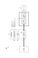
- the specimen testing system 100 of this embodiment tests a specimen W, which is an electrical device.
- the specimen W which is an electrical device, includes any one of a battery, an inverter, an electric motor, an inverter-integrated motor in which an inverter and a motor are integrated, or an electric axle (eAxle) in which an inverter, a motor, and a transmission are integrated.
- a battery mounted on a vehicle including, for example, a four-wheeled vehicle, a two-wheeled vehicle, or a railway vehicle
- examples of the battery include a lithium-ion battery, a lead-acid battery, a fuel cell, and an all-solid-state battery.
- the specimen testing system 100 includes a thermostatic chamber 2 that houses the specimen W, a charge/discharge device 3 that charges/discharges the battery that is the specimen W, a test power line 4 that is connected to the specimen W and the charge/discharge device 3, and a temperature adjustment device 5 that adjusts the temperature of the test power line 4 that is connected to the specimen W.
- the specimen testing system 100 may be configured without the thermostatic chamber 2.
- the constant temperature chamber 2 simulates the ambient temperature environment (sealedness, heat dissipation by air flow, etc.) of the battery under test W. If the battery under test W is water-cooled or liquid-cooled, a liquid circulation type battery temperature control device may be used to control the temperature of the battery. The battery temperature control device may also simulate the behavior of a circulation type temperature control system in an actual vehicle.
- the thermostatic chamber 2 has a storage space for storing the specimen W, and is configured so that the storage space can be kept at a predetermined temperature.
- the thermostatic chamber 2 is formed, for example, from resin or a metal such as aluminum. Note that a heat insulating material may be provided on the inner surface of the thermostatic chamber 2.
- the charging/discharging device 3 charges and discharges the battery, which is the test specimen W, so as to simulate the operation of an inverter or electric motor connected to the test specimen W.
- the test power line 4 has a connection terminal at one end that is connected to the external terminal of the test specimen W, and a connection terminal at the other end that is connected to the external terminal of the charging/discharging device 3.
- This test power line 4 is an insulated electric wire whose conductor is covered with an insulator, but it may also be a bare electric wire whose conductor is not covered with an insulator.
- the thickness of the insulator may be reduced only in the part whose temperature is regulated by the temperature regulation device 5 described below, or only the part whose temperature is regulated by the temperature regulation device 5 may not be covered with an insulator.
- the temperature adjustment device 5 adjusts the temperature of the test power line 4 so that it is equivalent to the temperature during actual use of the specimen W.
- the actual use of the specimen W refers to the time when the device on which the specimen W is mounted is operating.
- the device on which the specimen W is mounted may be a vehicle or something other than a vehicle. If the device on which the specimen W is mounted is a vehicle, the actual use of the specimen W includes the time when the vehicle is running (including the time when the vehicle is running, idling, stopped, or starting up), the time when the vehicle is stopped other than when it is running, or when charging.
- This temperature adjustment device 5 adjusts the temperature of the test power line 4 so as to simulate the heat input or heat dissipation through the actual power line connected to the specimen W during actual use of the specimen W.
- the actual power line is a power line that is owned by the vehicle on which the specimen W is mounted and is connected to the specimen W.
- the temperature adjustment device 5 includes a temperature regulator 51 that adjusts the temperature of the test power line 4, a target temperature calculation unit 52 that calculates the target temperature of the test power line 4, and a control unit 53 that controls the temperature regulator 51 based on the target temperature obtained by the target temperature calculation unit 52.
- An electronic temperature regulator can be used as this temperature adjustment device 5.
- the target temperature calculation unit 52 and the control unit 53 are configured using a computer equipped with a CPU, memory, input/output interface, etc., and their functions are fulfilled by the CPU and peripheral devices working together in accordance with the specimen test program stored in the memory.
- the temperature regulator 51 has a heater and/or a cooler arranged around the test power line 4.
- a heating resistor or a heat transfer pipe can be used as the heater.
- an electronic cooling element such as a Peltier element or a heat transfer pipe can be used as the cooler.
- the temperature regulator 51 may be arranged on the entire test power line 4 or on a part of it. When the temperature regulator 51 is arranged on a part of the test power line 4, it is desirable to arrange it on the side of the test specimen W (for example, near the connection terminal to the test specimen W).
- the temperature regulator 51 may be incorporated inside the test power line 4.
- the target temperature calculation unit 52 calculates the target temperature of the test power line using the amount of heat generated or the temperature of the equipment connected via the actual power line during actual use of the specimen W.
- the target temperature calculation unit 52 also calculates the target temperature of the test power line 4 using the amount of heat generated by the specimen W during testing, the thermal characteristics of the test power line 4, the thermal characteristics of the actual power line connected during actual use of the specimen W, and/or the thermal characteristics other than the amount of heat generated by the equipment connected via the actual power line during actual use of the specimen W, in addition to the amount of heat generated or the temperature of the equipment connected via the actual power line during actual use of the specimen W.
- the target temperature calculation unit 52 calculates the target temperature of the test power line 4 based on the parameters of the test specimen W, the parameters of the actual vehicle in which the test specimen W is mounted, and/or the parameters of the test power line 4.
- the parameters of the specimen W used to calculate the target temperature are at least one of the following (a) and (b).
- (a) The amount of heat generated by the test specimen W during testing e.g., heat generated by electrical current, etc.
- (b) Ambient temperature of the specimen W internal temperature of the thermostatic chamber, etc.
- the actual vehicle parameters used to calculate the target temperature are at least one of the following (a) and (b).
- (a) Thermal characteristics such as heat capacity, heat generation amount, thermal conductivity, and/or heat dissipation characteristics of an actual power line connected to the test piece W in an actual vehicle;
- (b) Thermal characteristics such as heat capacity, heat generation amount, thermal conductivity and/or heat dissipation characteristics of an inverter and/or an electric motor connected to the test piece W via an actual power line in an actual vehicle, etc.
- the parameters of the test power line 4 used to calculate the target temperature include thermal characteristics such as the heat capacity, heat generation amount, thermal conductivity, and/or heat dissipation characteristics of the test power line 4.
- the target temperature calculation unit 52 simulates a model equivalent to an actual vehicle to calculate an estimate of the temperature of the actual power line in the actual vehicle. Then, using the estimate of the temperature of the actual power line and the above-mentioned parameters, the target temperature calculation unit 52 calculates the target temperature of the test power line 4, taking into account the difference between the model equivalent to the actual vehicle used in the simulation and the experimental model of the specimen test system.
- the target temperature calculation unit 52 may calculate the target temperature of the test power line 4 using a measured value of the temperature of the actual power line in an actual vehicle obtained from a past test such as a road test or a bench test. In this case, the target temperature calculation unit 52 may calculate the target temperature of the test power line 4 using the measured value of the temperature of the actual power line and the above-mentioned parameters, taking into account the difference between the actual vehicle model used in the test and the experimental model of the specimen test system. Alternatively, the target temperature calculation unit 52 may calculate the target temperature of the test power line 4 using only the above-mentioned parameters, without using an estimated value or measured value of the temperature of the actual power line.
- the target temperature calculation unit 52 may also calculate the target temperature of the test power line 4 using a measurement value of the temperature of the actual power line in an actual vehicle obtained from a road test or bench test being performed in real time, or from a past road test or bench test. In this case, the target temperature calculation unit 52 may calculate the target temperature of the test power line 4 using the measurement value of the temperature of the actual power line and each of the above parameters, taking into account the difference between the actual vehicle model used in the test and the experimental model of the specimen test system.
- control unit 53 controls the temperature regulator 51 based on the target temperature obtained by the target temperature calculation unit 52, thereby simulating the heat input or heat dissipation through the actual power line when the test specimen W is actually used (in this case, when the vehicle is running).
- the target temperature calculation unit 52 and the control unit 53 may be provided in a control device (not shown) that controls the thermostatic chamber 2 or the charge/discharge device 3 described above.
- Temperature adjustment method 1 First, the temperature of the actual power line during actual use of the specimen W is obtained by simulation, or the temperature of the actual power line during actual use of the specimen W is obtained by actual measurement. Next, the obtained temperature of the actual power line is corrected using at least one of the above-mentioned parameters to calculate a target temperature of the test power line 4 . Then, the temperature adjusting device 5 is controlled based on the calculated target temperature to adjust the temperature of the test power line 4 .
- Temperature adjustment method 2 First, the temperature of the actual power line during actual use of the specimen W is obtained by simulation, or the temperature of the actual power line during actual use of the specimen W is obtained by actual measurement. The temperature of the actual power line thus found is then set as the target temperature of the test power line 4 , and the temperature adjustment device 5 is controlled based on the target temperature to adjust the temperature of the test power line 4 .
- Temperature adjustment method 3 At least one of the above parameters is used to calculate the target temperature of the test power line 4 . Then, the temperature adjusting device 5 is controlled based on the calculated target temperature to adjust the temperature of the test power line 4 .
- the test specimen W is placed inside the thermostatic chamber 2.
- the charge/discharge device 3 is connected to the test specimen W placed in the thermostatic chamber 2 via the test power line 4.
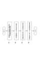
- the thermostatic chamber 2 is then used to simulate the ambient temperature environment during actual use of the test specimen W (step S1).
- the charging/discharging device 3 charges and discharges the test specimen W (battery) so as to simulate the operation of an inverter or electric motor connected to the test specimen W during actual use of the test specimen W (step S2).
- the target temperature calculation unit 52 calculates the target temperature of the test power line 4 using the amount of heat generated by the test specimen W during testing, the thermal characteristics of the test power line 4, the thermal characteristics of the actual power line connected to the specimen W during actual use, and/or the thermal characteristics other than the amount of heat generated by the equipment connected to the specimen W via the actual power line during actual use, in addition to the amount of heat generated or the temperature of the equipment connected to the specimen W via the actual power line (step S3). Note that the order of steps S2 and S3 above may be reversed.
- control unit 53 controls the temperature regulator 51 based on the target temperature obtained by the target temperature calculation unit 52.
- the temperature of the test power line 4 connected to the specimen W is adjusted by the temperature adjustment device 5, so that the specimen can be tested while simulating the thermal environment during actual use of the specimen W, specifically, the heat input or dissipation via the actual power line connected during actual use.
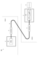
- the specimen W in the above embodiment was a battery, but as shown in FIG. 3, an inverter, an electric motor, an inverter-integrated motor in which an inverter and a motor are integrated, or an electric axle (eAxle) in which an inverter, a motor, and a transmission are integrated may be used as the specimen W. Even with these specimens W, a test can be performed in the same manner as in the flowchart of FIG. 2 in the above embodiment. Note that FIG. 3 shows a case in which both an inverter and an electric motor are used as the specimen W.
- the specimen testing system 100 further includes a power supply device 7 that supplies power to the inverter, and the test power line 4 is configured to connect the inverter and the power supply device 7.
- the power supply device 7 supplies power to the inverter so as to simulate the behavior of a battery.
- a dynamometer 8 is connected to the electric motor.
- the temperature adjustment device 5 that adjusts the temperature of the test power line 4 adjusts the temperature of the test power line 4 so as to simulate the heat input or heat dissipation through the actual power line during actual use of the specimen W, as in the above embodiment.
- both the battery and the inverter may be used as the specimen W.
- an electric motor is also used as the specimen.
- the test power line 4 is configured to connect the battery as the specimen W and the inverter as the specimen W.
- the temperature adjustment device 5 adjusts the temperature of the test power line 4 so as to simulate heat input or heat dissipation through the actual power line for testing. With this configuration, it is possible to test both the battery and the inverter (electric motor) simultaneously while transmitting and receiving power between the battery as the specimen W and the inverter as the specimen W.
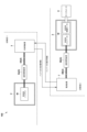
- two temperature adjustment devices 5 are provided, one on the battery side, which is the specimen W, and the other on the inverter side, which is the specimen W.
- a temperature adjustment device 5 on both the battery side and the inverter side in this way, even if the test room (test room 1) where the battery is tested and the test room (test room 2) where the inverter is tested are separate, it is possible to simulate the heat input and heat dissipation via the actual power lines to the battery and the inverter, respectively. As a result, it is possible to test both the battery and the inverter simultaneously under conditions that are closer to those during actual use.
- the specimen testing system 100 may further include a charging/discharging device 3 that charges and discharges the battery, and a power supply device 7 that supplies power to the inverter.
- the test power line 4 has a first test power line 4A that connects the battery and the charging/discharging device 3, and a second test power line 4B that connects the inverter and the power supply device 7.
- the temperature adjustment device 5 has a first temperature adjustment device 5A that adjusts the temperature of the first test power line 4A, and a second temperature adjustment device 5B that adjusts the temperature of the second test power line 4B.
- Each test power line 4A, 4B has the same configuration as in the above embodiment.
- Each temperature adjustment device 5A, 5B has the same configuration as in the above embodiment.
- the charging/discharging device 3 and the power supply device 7 are configured to be able to communicate with each other. Being configured to be able to communicate with each other includes being configured to be able to communicate with a control device (not shown) that controls the charging/discharging device 3 and a control device (not shown) that controls the power supply device 7.
- the charging/discharging device 3 reproduces the behavior of the inverter under test, and the power supply device 7 reproduces the behavior of the battery. Specifically, the charging/discharging device 3 transmits battery charge/discharge information to the power supply device 7, and the power supply device 7 that receives the charge/discharge information supplies power to the inverter based on the charge/discharge information.
- the power supply device 7 also transmits inverter operation information to the charging/discharging device 3, and the charging/discharging device 3 that receives the operation information charges and discharges the battery based on the operation information.
- the temperature adjustment device 5 may adjust the temperature of the test power line 4 so that it is the temperature of the actual power line connected to the specimen W when the specimen W is in actual use.
- the target temperature of the test power line 4 is the temperature of the actual power line when the specimen W is in actual use.
- the temperature of the actual power line when in actual use may be determined by simulation, may be obtained from a past test such as a road test or a bench test, or may be obtained from a test such as a road test or a bench test that is performed in real time.
- the target temperature of the test power line 4 may be the temperature of the actual power line that changes over time (for example, the actual power line temperature from the start of the test to the end of the test), or it may be the temperature of the actual power line at a certain time (for example, the actual power temperature at the time when the temperature of the actual power line is the highest).
- the battery as the specimen in the above embodiment is mounted on a vehicle, but it may be mounted on a moving body other than a vehicle or a stationary power storage device.
- the actual power line is a power line that is possessed by the moving body other than a vehicle or the stationary power storage device and is connected to the specimen W.
- moving bodies other than vehicles include aircraft, drones, and ships
- stationary power storage devices include factory/plant power storage devices or home power storage devices.
- the actual use of the specimen W may refer to the charging and/or discharging of the specimen in the device in which the specimen is mounted (such as a vehicle, a moving body other than a vehicle, or a stationary power storage device).
- the specimen testing system 100 may be configured without the thermostatic chamber 2, or may be configured with a reproduction device that reproduces the environment during actual vehicle operation.
- the test specimen may be an in-vehicle electrical device other than a battery, inverter, or electric motor, or it may be a non-in-vehicle electrical device.
- the test performed by the specimen testing system of the present invention may be a heat generation test of the battery.
- This heat generation test of the battery may be, for example, a safety evaluation test to check for abnormal heat generation, or a performance evaluation test to check the heat dissipation characteristics of the battery. It may also be a driving mode test that takes into account the driving mode of the vehicle in which the battery is installed.
- the test performed by the specimen testing system of the present invention may also be a test of the degree of deterioration of a battery.
- This test of the degree of deterioration of a battery may, for example, be an evaluation test on the degree of deterioration of a reused battery or a battery under development.
- the test performed by the specimen testing system of the present invention may also be an evaluation test of a battery pack or a battery case.
- This evaluation test of a battery pack or a battery case may, for example, be an evaluation test of the thermal characteristics of a battery pack, or an evaluation test of the cooling performance or thermal characteristics of a battery case.
- the present invention makes it possible to test a specimen while simulating the heat input or heat dissipation through an actual power line during actual use.
- Test specimen testing system W Test specimen 2: Thermostatic chamber 3: Charging/discharging device 4: Test power line 4A: First test power line 4B: Second test power line 5: Temperature adjustment device 51: Temperature adjuster 52: Target temperature calculation unit 53: Control unit 5A: First temperature adjustment device 5B: Second temperature adjustment device 7: Power supply device
Landscapes
- Physics & Mathematics (AREA)
- General Physics & Mathematics (AREA)
- Charge And Discharge Circuits For Batteries Or The Like (AREA)
- Testing Electric Properties And Detecting Electric Faults (AREA)
Abstract
Description
ここで、供試体の実使用時において接続された実電力線の温度は、シミュレーションによって求めたものでも良いし、過去の路上走行試験又は台上試験等の試験により得られたものであっても良いし、リアルタイムで行われている路上走行試験又は台上試験等の試験により得られたものであっても良い。
そのため、前記温度調整装置は、前記試験用電力線の温度を調整する温度調整器と、前記供試体の実使用時において前記実電力線を介して接続される機器の発熱量又は温度を用いて、前記試験用電力線の目標温度を算出する目標温度算出部と、前記目標温度算出部により得られた前記目標温度に基づいて前記温度調整器を制御する制御部とを備えることが望ましい。
そのため、前記目標温度算出部は、前記供試体の実使用時において前記実電力線を介して接続される機器の発熱量又は温度に加えて、前記供試体の試験時における発熱量、前記試験用電力線の熱特性、前記供試体の実使用時に接続される実電力線の熱特性、及び/又は、前記供試体の実使用時において前記実電力線を介して接続される機器の発熱量及び温度以外の熱特性を用いて、前記試験用電力線の目標温度を算出することが望ましい。
この構成であれば、実使用時により近い条件で、実電力線を介した入熱又は放熱を模擬することができる。
この構成であれば、車両走行時における実電力線を介した入熱又は放熱を模擬しつつ、供試体を試験することができる。
この構成であれば、供試体に接続される実電力線を介した入熱又は放熱だけでなく、供試体の周囲にある空気との間の入熱又は放熱を模擬しつつ、供試体を試験することができる。
この構成によれば、供試体であるバッテリと供試体であるインバータとの間で電力の授受を行いながら、バッテリ及びインバータの両方を同時に試験することができる。
この構成において、前記充放電装置及び前記電源装置は、相互に通信可能に構成されており、前記充放電装置は、前記インバータの挙動を再現し、前記電源装置は、前記バッテリの挙動を再現するものであることが望ましい。
この構成であれば、バッテリの試験を行う試験室とインバータの試験を行う試験室とが別々であっても、バッテリ及びインバータの両方を同時に試験することができる。また、第1試験用電力線及び第2試験用電力線を短くすることができるので、それら試験用電力線における電力損失を低減することができる。
以下に、本発明に係る供試体試験システムの一実施形態について、図面を参照して説明する。なお、以下に示すいずれの図についても、わかりやすくするために、適宜省略し又は誇張して模式的に描かれている。同一の構成要素については、同一の符号を付して説明を適宜省略する。
本実施形態の供試体試験システム100は、電気機器である供試体Wを試験するものである。電気機器である供試体Wとしては、バッテリ、インバータ、電動モータ、インバータとモータとが一体となったインバータ一体型モータ、又は、インバータとモータと変速機とが一体となった電動アクスル(eAxle)の何れか1つを含む。以下では、供試体Wとして、車両(例えば、四輪自動車、二輪自動車又は鉄道車両等を含む。)に搭載されるバッテリを例として説明する。なお、バッテリとしては、リチウムイオン電池、鉛蓄電池、燃料電池又は全固体電池等を挙げることができる。
(a)供試体Wの試験時における発熱量(例えば通電による発熱等)、
(b)供試体Wの周囲温度(恒温槽の内部温度)、等
(a)実車において供試体Wに接続される実電力線の熱容量、発熱量、熱伝導率及び/又は放熱特性等の熱特性、
(b)実車において供試体Wに実電力線を介して接続されるインバータ及び/又は電動モータの熱容量、発熱量、熱伝導率及び/又は放熱特性等の熱特性、等
次に、試験用電力線4の温度調整方法について説明する。
まず、供試体Wの実使用時における実電力線の温度をシミュレーションにより求め、又は、供試体Wの実使用時における実電力線の温度を実測して求める。
次に、求めた実電力線の温度を、上述したパラメータの少なくとも1つを用いて補正し、試験用電力線4の目標温度を算出する。
そして、算出した目標温度に基づいて、温度調整装置5を制御して、試験用電力線4の温度を調整する。
まず、供試体Wの実使用時における実電力線の温度をシミュレーションにより求め、又は、供試体Wの実使用時における実電力線の温度を実測して求める。
そして、求めた実電力線の温度を試験用電力線4の目標温度とし、当該目標温度に基づいて、温度調整装置5を制御して、試験用電力線4の温度を調整する。
上述したパラメータの少なくとも1つを用いて試験用電力線4の目標温度を算出する。
そして、算出した目標温度に基づいて、温度調整装置5を制御して、試験用電力線4の温度を調整する。
次に、本実施形態の供試体試験システム100を用いた供試体Wの試験方法について、図2を参照して説明する。
このように構成した本実施形態の供試体試験システム100によれば、温度調整装置5により供試体Wに接続された試験用電力線4の温度を調整するので、供試体Wの実使用時における熱環境、具体的には実使用時に接続される実電力線を介した入熱又は放熱を模擬しつつ、供試体を試験することができる。
例えば、前記実施形態の供試体Wは、バッテリであったが、図3に示すように、インバータ、電動モータ、インバータとモータとが一体となったインバータ一体型モータ、又は、インバータとモータと変速機とが一体となった電動アクスル(eAxle)を供試体Wとしても良い。これらの供試体Wであっても前記実施形態の図2のフローチャートと同様の流れで試験を行うことができる。なお、図3ではインバータ及び電動モータの両方を供試体Wとした場合を示している。この場合、供試体試験システム100は、インバータに電力を供給する電源装置7をさらに備えており、試験用電力線4は、インバータと電源装置7とを接続する構成となる。電源装置7は、バッテリの挙動を模擬するようにインバータに電力を供給する。また、電動モータには、ダイナモメータ8が接続されている。そして、試験用電力線4の温度を調整する温度調整装置5は、前記実施形態と同様に、供試体Wの実使用時の実電力線を介した入熱又は放熱を模擬するように、試験用電力線4の温度を調整する。
W ・・・供試体
2 ・・・恒温槽
3 ・・・充放電装置
4 ・・・試験用電力線
4A ・・・第1試験用電力線
4B ・・・第2試験用電力線
5 ・・・温度調整装置
51 ・・・温度調整器
52 ・・・目標温度算出部
53 ・・・制御部
5A ・・・第1温度調整装置
5B ・・・第2温度調整装置
7 ・・・電源装置
Claims (15)
- 電気機器である供試体を試験する供試体試験システムであって、
前記供試体に接続される試験用電力線と、
前記供試体に接続された前記試験用電力線の温度を調整する温度調整装置とを備える、供試体試験システム。 - 前記温度調整装置は、前記供試体の実使用時の前記供試体に接続される実電力線を介した入熱又は放熱を模擬するように、前記試験用電力線の温度を調整する、請求項1に記載の供試体試験システム。
- 前記温度調整装置は、前記供試体の実使用時の前記供試体に接続される実電力線の温度を模擬するように、前記試験用電力線の温度を調整する、請求項1又は2に記載の供試体試験システム。
- 前記温度調整装置は、
前記試験用電力線の温度を調整する温度調整器と、
前記供試体の実使用時において前記実電力線を介して接続される機器の発熱量又は温度を用いて、前記試験用電力線の目標温度を算出する目標温度算出部と、
前記目標温度算出部により得られた前記目標温度に基づいて前記温度調整器を制御する制御部とを備える、請求項1乃至3の何れか一項に記載の供試体試験システム。 - 前記目標温度算出部は、前記供試体の実使用時において前記実電力線を介して接続される機器の発熱量又は温度に加えて、前記供試体の試験時における発熱量、前記試験用電力線の熱特性、前記供試体の実使用時に接続される実電力線の熱特性、及び/又は、前記供試体の実使用時において前記実電力線を介して接続される機器の発熱量及び温度以外の熱特性を用いて、前記試験用電力線の目標温度を算出する、請求項4に記載の供試体試験システム。
- 前記供試体の実使用時において前記実電力線を介して接続される機器の発熱量又は温度は、シミュレーション又は実測により得られたものである、請求項4又は5に記載の供試体試験システム。
- 前記供試体は、車両に搭載されるものであり、
前記供試体の実使用時は、車両走行時、停車時又は充電時である、請求項2乃至6の何れか一項に記載の供試体試験システム。 - 前記供試体を収容する恒温槽をさらに備える、請求項1乃至7の何れか一項に記載の供試体試験システム。
- 前記供試体がバッテリであり、
前記供試体試験システムは、前記バッテリを充放電する充放電装置をさらに備え、
前記試験用電力線は、前記バッテリと前記充放電装置とを接続するものである、請求項1乃至8の何れか一項に記載の供試体試験システム。 - 前記供試体がインバータであり、
前記供試体試験システムは、前記インバータに電力を供給する電源装置をさらに備え、
前記試験用電力線は、前記インバータと前記電源装置とを接続するものである、請求項1乃至8の何れか一項に記載の供試体試験システム。 - 前記供試体がバッテリ及びインバータであり、
前記試験用電力線は、前記バッテリと前記インバータとを接続するものである、請求項1乃至8の何れか一項に記載の供試体試験システム。 - 前記供試体がバッテリ及びインバータであり、
前記供試体試験システムは、
前記バッテリを充放電する充放電装置と、
前記インバータに電力を供給する電源装置をさらに備え、
前記試験用電力線は、
前記バッテリと前記充放電装置とを接続する第1試験用電力線と、
前記インバータと前記電源装置とを接続する第2試験用電力線とを有し、
前記温度調整装置は、
前記第1試験用電力線の温度を調整する第1温度調整装置と、
前記第2試験用電力線の温度を調整する第2温度調整装置とを有し、
前記充放電装置及び前記電源装置は、相互に通信可能に構成されており、前記充放電装置は、前記インバータの挙動を再現し、前記電源装置は、前記バッテリの挙動を再現するものである、請求項1乃至8の何れか一項に記載の供試体試験システム。 - 電気機器である供試体の試験に用いられる温度調整装置であって、
前記供試体に接続される試験用電力線の温度を調整する温度調整器と、
前記供試体の実使用時の前記供試体に接続される実電力線を介した入熱又は放熱を模擬するように、前記温度調整器を制御する制御部とを備える、温度調整装置。 - 電気機器である供試体を試験する供試体試験方法であって、
前記供試体に試験用電力線を接続し、前記試験用電力線の温度を調整して、前記供試体を試験する、供試体試験方法。 - 電気機器である供試体に接続される試験用電力線と、当該試験用電力線の温度を調整する温度調整器とを有する供試体試験システムに用いられるプログラムであって、
前記供試体の実使用時の前記供試体に接続される実電力線を介した入熱又は放熱を模擬するように、前記温度調整器を制御する制御部としての機能をコンピュータに備えさせる、供試体試験用プログラム。
Priority Applications (2)
| Application Number | Priority Date | Filing Date | Title |
|---|---|---|---|
| DE112024002799.7T DE112024002799T5 (de) | 2023-06-30 | 2024-06-12 | Testproben-prüfsystem, temperatureinstellungsvorrichtung, testproben-prüfverfahren und testproben-prüfprogramm |
| JP2025529618A JPWO2025004803A1 (ja) | 2023-06-30 | 2024-06-12 |
Applications Claiming Priority (2)
| Application Number | Priority Date | Filing Date | Title |
|---|---|---|---|
| JP2023108473 | 2023-06-30 | ||
| JP2023-108473 | 2023-06-30 |
Publications (1)
| Publication Number | Publication Date |
|---|---|
| WO2025004803A1 true WO2025004803A1 (ja) | 2025-01-02 |
Family
ID=93938794
Family Applications (1)
| Application Number | Title | Priority Date | Filing Date |
|---|---|---|---|
| PCT/JP2024/021305 Ceased WO2025004803A1 (ja) | 2023-06-30 | 2024-06-12 | 供試体試験システム、温度調整装置、供試体試験方法、及び、供試体試験用プログラム |
Country Status (3)
| Country | Link |
|---|---|
| JP (1) | JPWO2025004803A1 (ja) |
| DE (1) | DE112024002799T5 (ja) |
| WO (1) | WO2025004803A1 (ja) |
Citations (5)
| Publication number | Priority date | Publication date | Assignee | Title |
|---|---|---|---|---|
| JPH0786734A (ja) * | 1993-09-16 | 1995-03-31 | Matsushita Electric Ind Co Ltd | 電子回路の電気導通検査方法および電気導通検査装置ならびに電子回路 |
| JP2016014592A (ja) * | 2014-07-02 | 2016-01-28 | トヨタ自動車株式会社 | 電池パックの耐久試験方法 |
| CN106248251A (zh) * | 2016-08-29 | 2016-12-21 | 河南省龙祥电力电缆有限公司 | 一种电动汽车用电瓶连接线的测试实验装置 |
| CN112564206A (zh) * | 2020-11-18 | 2021-03-26 | 湖北亿纬动力有限公司 | 电池均衡评价系统及方法 |
| JP3242247U (ja) * | 2023-02-27 | 2023-06-05 | 中国長江三峡集団有限公司 | エネルギー貯蔵電池試験用の温度調節装置 |
Family Cites Families (1)
| Publication number | Priority date | Publication date | Assignee | Title |
|---|---|---|---|---|
| JP2007292654A (ja) | 2006-04-26 | 2007-11-08 | Toyota Motor Corp | 車載用電池の耐久試験装置 |
-
2024
- 2024-06-12 JP JP2025529618A patent/JPWO2025004803A1/ja active Pending
- 2024-06-12 DE DE112024002799.7T patent/DE112024002799T5/de active Pending
- 2024-06-12 WO PCT/JP2024/021305 patent/WO2025004803A1/ja not_active Ceased
Patent Citations (5)
| Publication number | Priority date | Publication date | Assignee | Title |
|---|---|---|---|---|
| JPH0786734A (ja) * | 1993-09-16 | 1995-03-31 | Matsushita Electric Ind Co Ltd | 電子回路の電気導通検査方法および電気導通検査装置ならびに電子回路 |
| JP2016014592A (ja) * | 2014-07-02 | 2016-01-28 | トヨタ自動車株式会社 | 電池パックの耐久試験方法 |
| CN106248251A (zh) * | 2016-08-29 | 2016-12-21 | 河南省龙祥电力电缆有限公司 | 一种电动汽车用电瓶连接线的测试实验装置 |
| CN112564206A (zh) * | 2020-11-18 | 2021-03-26 | 湖北亿纬动力有限公司 | 电池均衡评价系统及方法 |
| JP3242247U (ja) * | 2023-02-27 | 2023-06-05 | 中国長江三峡集団有限公司 | エネルギー貯蔵電池試験用の温度調節装置 |
Also Published As
| Publication number | Publication date |
|---|---|
| JPWO2025004803A1 (ja) | 2025-01-02 |
| DE112024002799T5 (de) | 2026-04-16 |
Similar Documents
| Publication | Publication Date | Title |
|---|---|---|
| Lin et al. | Online parameterization of lumped thermal dynamics in cylindrical lithium ion batteries for core temperature estimation and health monitoring | |
| Chen et al. | Loss-minimization-based charging strategy for lithium-ion battery | |
| US8679658B2 (en) | Methods and systems for conditioning energy storage systems of vehicles | |
| KR101101947B1 (ko) | 배터리 관리시스템의 배터리 시뮬레이터 | |
| JP2005011757A (ja) | 二次電池の温度異常検知装置および異常検知方法 | |
| Chang et al. | Effects of reciprocating liquid flow battery thermal management system on thermal characteristics and uniformity of large lithium‐ion battery pack | |
| US7609032B2 (en) | Device and method for ascertaining the temperature in an electrical battery | |
| JP2021009103A (ja) | 電池制御システム | |
| Estevez et al. | Aging estimation of lithium ion cells under real-world conditions through mechanical stress measurements | |
| KR20150028095A (ko) | 배터리 팩의 프리차지 저항 산출 장치 및 방법 | |
| Sok et al. | A Methodology to Develop and Validate a 75-kWh Battery Pack Model with Its Cooling System under a Real Driving Cycle | |
| CN115856670B (zh) | 电池发热量的计算方法及装置、电池和车辆 | |
| CN104241722B (zh) | 电池组热敏电阻测试方法 | |
| Worwood et al. | A study into different cell-level cooling strategies for cylindrical lithium-ion cells in automotive applications | |
| Han et al. | Safe bidirectional pulse heating method for the lithium-ion battery pack on a high-power electric motorcycle | |
| US20230299376A1 (en) | Secondary battery system, controller and control method for secondary battery system, and non-transitory computer readable medium storing program for secondary battery system controller | |
| Geringer et al. | Aging investigations and consideration for automotive high power lithium-ion batteries in a 48 V mild hybrid operating strategy | |
| CN110806542A (zh) | 一种动力电池测试系统及方法 | |
| Vega et al. | Efficient internal resistance and specific heat identification of li-ion battery at low temperature conditions | |
| Gravante et al. | A novel experimental testing setup and calibration procedures for cylindrical cell thermal models | |
| Capasso et al. | Experimental investigation of lithium-ion battery cells for model-based thermal management systems | |
| CN113779750B (zh) | 基于充电状态的电池寿命预测方法、系统及充电桩 | |
| Bhat et al. | Thermal impact of PCM thickness on a cylindrical Li-ion cell | |
| Yang et al. | Modeling validation of key life test for hybrid electric vehicle batteries | |
| Soloy et al. | Modelling and fault diagnosis of lithium-ion battery for electric powertrain |
Legal Events
| Date | Code | Title | Description |
|---|---|---|---|
| 121 | Ep: the epo has been informed by wipo that ep was designated in this application |
Ref document number: 24831669 Country of ref document: EP Kind code of ref document: A1 |
|
| ENP | Entry into the national phase |
Ref document number: 2025529618 Country of ref document: JP Kind code of ref document: A |
|
| WWE | Wipo information: entry into national phase |
Ref document number: 2025529618 Country of ref document: JP |
|
| WWE | Wipo information: entry into national phase |
Ref document number: 112024002799 Country of ref document: DE |
|
| WWP | Wipo information: published in national office |
Ref document number: 112024002799 Country of ref document: DE |