WO2025004633A1 - 物質供給システム及び物質容器 - Google Patents
物質供給システム及び物質容器 Download PDFInfo
- Publication number
- WO2025004633A1 WO2025004633A1 PCT/JP2024/018953 JP2024018953W WO2025004633A1 WO 2025004633 A1 WO2025004633 A1 WO 2025004633A1 JP 2024018953 W JP2024018953 W JP 2024018953W WO 2025004633 A1 WO2025004633 A1 WO 2025004633A1
- Authority
- WO
- WIPO (PCT)
- Prior art keywords
- unit
- substance
- container
- opening
- closing
- Prior art date
- Legal status (The legal status is an assumption and is not a legal conclusion. Google has not performed a legal analysis and makes no representation as to the accuracy of the status listed.)
- Ceased
Links
Images




Classifications
-
- C—CHEMISTRY; METALLURGY
- C01—INORGANIC CHEMISTRY
- C01B—NON-METALLIC ELEMENTS; COMPOUNDS THEREOF; METALLOIDS OR COMPOUNDS THEREOF NOT COVERED BY SUBCLASS C01C
- C01B3/00—Hydrogen; Gaseous mixtures containing hydrogen; Separation of hydrogen from mixtures containing it; Purification of hydrogen; Reversible storage of hydrogen
- C01B3/02—Production of hydrogen; Production of gaseous mixtures containing hydrogen
- C01B3/06—Production of hydrogen; Production of gaseous mixtures containing hydrogen by reaction of inorganic compounds containing electro-positively bound hydrogen with inorganic reducing agents
-
- F—MECHANICAL ENGINEERING; LIGHTING; HEATING; WEAPONS; BLASTING
- F17—STORING OR DISTRIBUTING GASES OR LIQUIDS
- F17C—VESSELS FOR CONTAINING OR STORING COMPRESSED, LIQUEFIED OR SOLIDIFIED GASES; FIXED-CAPACITY GAS-HOLDERS; FILLING VESSELS WITH, OR DISCHARGING FROM VESSELS, COMPRESSED, LIQUEFIED, OR SOLIDIFIED GASES
- F17C11/00—Use of gas-solvents or gas-sorbents in vessels
-
- F—MECHANICAL ENGINEERING; LIGHTING; HEATING; WEAPONS; BLASTING
- F17—STORING OR DISTRIBUTING GASES OR LIQUIDS
- F17C—VESSELS FOR CONTAINING OR STORING COMPRESSED, LIQUEFIED OR SOLIDIFIED GASES; FIXED-CAPACITY GAS-HOLDERS; FILLING VESSELS WITH, OR DISCHARGING FROM VESSELS, COMPRESSED, LIQUEFIED, OR SOLIDIFIED GASES
- F17C7/00—Methods or apparatus for discharging liquefied, solidified, or compressed gases from pressure vessels, not covered by another subclass
-
- F—MECHANICAL ENGINEERING; LIGHTING; HEATING; WEAPONS; BLASTING
- F23—COMBUSTION APPARATUS; COMBUSTION PROCESSES
- F23K—FEEDING FUEL TO COMBUSTION APPARATUS
- F23K5/00—Feeding or distributing other fuel to combustion apparatus
-
- H—ELECTRICITY
- H01—ELECTRIC ELEMENTS
- H01M—PROCESSES OR MEANS, e.g. BATTERIES, FOR THE DIRECT CONVERSION OF CHEMICAL ENERGY INTO ELECTRICAL ENERGY
- H01M8/00—Fuel cells; Manufacture thereof
- H01M8/06—Combination of fuel cells with means for production of reactants or for treatment of residues
- H01M8/0606—Combination of fuel cells with means for production of reactants or for treatment of residues with means for production of gaseous reactants
Definitions
- the present invention relates to a material supply system that supplies a material from a material container to a material receiving section, or supplies a material from a material supply section to a material container, and to a material container in which a material is stored.
- a hydrogen generating device has been proposed that is equipped with a removable fuel cartridge and has a fuel cartridge with a memory section that stores the amount of water supplied or the remaining amount of hydrogen that can be generated (Patent Document 1).
- substances such as fuel used in hydrogen generation devices are stored and transported in substance containers such as fuel cartridges.
- the stored substance is fuel, it may be undesirable from a safety standpoint if the substance container can be opened and closed by anyone.
- the substance stored in the substance container is not fuel but has trade value, there is a risk that the substance inside may be stolen if the container can be opened and closed by anyone.
- the present invention aims to provide a configuration that can prevent a substance container from being opened or closed by anyone.
- the material supply system of the present invention is a material supply system comprising a material container in which a material is stored, and a material receiving unit connected to the material container to receive a supply of material from the material container, the material container comprising a storage unit in which the material is stored, a first material passageway connecting the storage unit with the outside and through which the material passes, an opening/closing unit provided in the first material passageway and electrically operable between a closed state in which the first material passageway is blocked and an open state in which the first material passageway is opened, a power receiving unit capable of receiving power from the outside and supplying power to the opening/closing unit, a control unit for controlling the opening and closing of the opening/closing unit, and a control unit for controlling the identification of the material container.
- the substance receiving unit has a second substance passage connected to the first substance passage, a supplied unit to which substance is supplied from the second substance passage, a power supply unit capable of supplying power to the power receiving unit, and a reading unit capable of reading information from the memory unit, and the control unit operates the opening/closing unit from the closed state to the open state or issues a signal permitting the opening/closing unit to operate from the closed state to the open state when the substance container is connected to the substance receiving unit and the information stored in the memory unit read by the reading unit satisfies a predetermined condition.
- the material supply system of the present invention is a material supply system comprising a material container in which a material is stored, and a material supply unit connected to the material container and supplying a material to the material container, the material container comprising a first storage unit in which a material is stored, a first material passageway connecting the first storage unit with the outside and through which the material passes, an opening/closing unit provided in the first material passageway and electrically operable between a closed state in which the first material passageway is blocked and an open state in which the first material passageway is opened, a power receiving unit capable of receiving power from the outside and supplying power to the opening/closing unit, a control unit for controlling the opening and closing of the opening/closing unit, and information relating to the identification of the material container.
- the substance supply unit has a second storage unit in which the substance is stored, a second substance passage that connects the second storage unit to the outside, through which the substance passes and that is connected to the first substance passage, a power supply unit capable of supplying power to the power receiving unit, and a reading unit capable of reading information from the memory unit, and the control unit operates the opening/closing unit from the closed state to the open state or issues a signal permitting the opening/closing unit to operate from the closed state to the open state when the substance container is connected to the substance supply unit and the information stored in the memory unit read by the reading unit satisfies a predetermined condition.
- the substance container of the present invention is a substance container that contains a substance, and has a container section in which the substance is contained, a substance passage that connects the container section to the outside and through which the substance passes, an opening/closing section that is provided in the substance passage and is electrically operable between a closed state that blocks the substance passage and an open state that opens the substance passage, a power receiving section that can receive power from the outside and supply power to the opening/closing section, a control section that controls the opening and closing of the opening/closing section, and a memory section that stores information related to the identification of the substance container and is capable of reading the information from the outside, and when the information stored in the memory section that is read from the outside satisfies a predetermined condition, the control section operates the opening/closing section from the closed state to the open state, or issues a signal that permits the opening/closing section to operate from the closed state to the open state.
- the present invention makes it possible to prevent anyone from opening and closing a substance container.
- FIG. 1 is a schematic cross-sectional view showing a fuel supply system according to a first embodiment in a disconnected state
- FIG. 2 is a schematic cross-sectional view showing a connection state of the fuel supply system according to the first embodiment
- FIG. 2 is a block diagram showing a control configuration of the fuel supply system according to the first embodiment
- FIG. 4 is a block diagram showing a control configuration of a fuel supply system according to another example of the first embodiment.
- FIG. 11 is a schematic cross-sectional view showing a fuel supply system according to a second embodiment in a disconnected state
- FIG. 11 is a schematic cross-sectional view showing a connection state of a fuel supply system according to a second embodiment of the present invention.
- FIG. 11 is a block diagram showing a control configuration of a fuel supply system according to a second embodiment.
- a first embodiment will be described with reference to Figs. 1 to 4.
- hydrogen has been attracting attention as an alternative energy source to fossil fuels. This is because, unlike fossil fuels, hydrogen does not generate carbon dioxide, a type of greenhouse gas that leads to global warming, when burned.
- One of the systems that use hydrogen as an energy source that has been put into practical use is a fuel cell vehicle.
- a fuel cell vehicle is a vehicle that generates electricity using hydrogen as a raw material and runs by driving an electric motor with the generated electricity.
- hydrogen which is an energy source
- the hydrogen tank stores hydrogen by compressing it at a high pressure, for example, 70 MPa (700 times atmospheric pressure).
- the volumetric energy density of hydrogen is about 1/3000 of that of gasoline, so even if a 70 MPa hydrogen tank is used, only about 1/5 of the energy of gasoline can be extracted from the same volume. For this reason, fuel cell vehicles that use hydrogen tanks generally require more frequent energy refueling than cars that use gasoline.
- hydrogen carriers various substances that can transport hydrogen at a higher energy density than hydrogen tanks (i.e., hydrogen carriers) are being considered.
- hydrogen carriers such as ammonia, methylcyclohexane, and sodium borohydride are known as hydrogen carriers, and hydrogen carriers are transported instead of hydrogen itself, and hydrogen is extracted from the hydrogen carrier when it is to be used.
- a fuel supply system 1000 is configured with a fuel container 101 and a hydrogen generating device 201.
- the substance contained in the fuel container 101 is a hydrogen carrier
- the device receiving the supply of the substance is the hydrogen generating device 201.
- the hydrogen carrier will be described.
- metal hydrides such as sodium borohydride are widely known, from which hydrogen can be easily extracted by adding water.
- As a method for obtaining hydrogen by hydrolysis of sodium borohydride a method for dissolving sodium borohydride in water and using it as an aqueous solution is known.
- a larger amount of water than the theoretically required amount shown in the reaction formula is required, which is problematic in that the actual volumetric energy density decreases.
- a solid hydrogen carrier is supplied to a hydrogen generating device from a fuel container 101 described later, and a liquid containing water is added to the hydrogen carrier in the hydrogen generating device 201 (specifically, a liquid containing water is poured onto the hydrogen carrier) to generate hydrogen.
- Hydrogen carriers that generate hydrogen when a liquid containing water is added include the following.
- one or a mixture of solid metal hydrides such as sodium borohydride, potassium borohydride, lithium borohydride, zinc borohydride, lithium aluminum hydride, sodium aluminum hydride, magnesium aluminum hydride, calcium aluminum hydride, magnesium hydride, lithium hydride, sodium hydride, and calcium hydride, and metal powders such as aluminum, zinc, calcium, and magnesium can be used.
- the substance contained in the substance container may contain additives such as a reaction accelerator and a desiccant in addition to the hydrogen carrier.
- the hydrogen carrier of this embodiment is preferably a solid.
- a solid hydrogen carrier a solid such as a powder or granule is desirable, but a solid such as a sheet, pellet, or paste can also be used.
- a powder a particle size of about 10 ⁇ m to 10 mm can be used, and a particle size of about 10 ⁇ m to 3 mm, and even more preferably a particle size of about 10 ⁇ m to 100 ⁇ m.
- sodium borohydride powder is used as the solid hydrogen carrier.
- the powdered sodium borohydride reacts with water to generate hydrogen.
- the reacted sodium borohydride changes into sodium metaborate, which is a by-product.
- This reaction is expressed by the following chemical formula. NaBH4 (sodium borohydride) + 2H2O (water) ⁇ NaBO2 (sodium metaborate) + 4H2 (hydrogen) ... (1)
- the water-containing liquid may be water alone, or may contain water plus a substance such as a water-soluble organic solvent, a surfactant, a water-soluble acidic substance, a water-soluble basic substance, or a buffer solution.
- the hydrogen generating device 201 in this embodiment may be configured in any way as long as it causes this reaction to generate hydrogen.
- FIG. 1 is a schematic cross-sectional view showing a state in which the fuel container 101 is not connected to the hydrogen generation device 201
- Figure 2 is a schematic cross-sectional view showing a state in which the fuel container 101 is connected to the hydrogen generation device 201
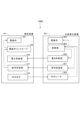
- Figure 3 is a block diagram showing the control configuration of the fuel supply system 1000, with arrows indicating transmission and reception of electrical signals in each device, supply and reception of power between the fuel container 101 and the hydrogen generation device 201, and transmission and reception of electrical signals.
- the fuel supply system 1000 as a material supply system includes a fuel container 101 as a material container, and a hydrogen generator 201 as a material receiver.
- the fuel container 101 contains a material (a solid hydrogen carrier in this embodiment).
- the material contained in the fuel container 101 may be a liquid hydrogen carrier, such as an aqueous solution of sodium borohydride dissolved in water, but as described above, in this embodiment, the material is a solid hydrogen carrier.
- the hydrogen generator 201 is connected to the fuel container 101 and receives a supply of material from the fuel container 101, and generates hydrogen by adding a liquid containing hydrogen carrier water supplied from the fuel container 101.
- the material receiver is not limited to the hydrogen generator 201, and may be a tank that stores a hydrogen carrier and does not have the function of generating hydrogen.
- the fuel container 101 as a substance container is used to store powdered sodium borohydride as a fuel.
- the fuel container 101 has a fuel storage section 102 as a storage section and a first storage section, a fuel passage 103 as a substance passage and a first substance passage, an electromagnetic valve 105 as an opening/closing section and a first opening/closing section, a power receiving section 106, an electromagnetic valve controller 108 as a control section and a first control section, an RFID (radio frequency identification) tag 104 as a memory section, and a signal receiving section 107.
- a fuel storage section 102 as a storage section and a first storage section
- a fuel passage 103 as a substance passage and a first substance passage
- an electromagnetic valve 105 as an opening/closing section and a first opening/closing section
- a power receiving section 106 an electromagnetic valve controller 108 as a control section and a first control section
- an RFID (radio frequency identification) tag 104 as a memory section
- the fuel storage section 102 contains a hydrogen carrier (powdered sodium borohydride in this embodiment), which is a substance (fuel in this embodiment).
- the fuel passage 103 connects the fuel storage section 102 to the outside, and is a passage through which the powdered sodium borohydride passes. In other words, the powdered sodium borohydride can enter and exit the fuel storage section 102 via the fuel passage 103.
- the solenoid valve 105 is provided in the fuel passage 103 and is electrically operable between a closed state in which the fuel passage 103 is blocked and an open state in which the fuel passage 103 is opened. When not energized, the solenoid valve 105 is in a closed state in which the fuel passage 103 is blocked, and is configured to open when energized by a command from the solenoid valve controller 108.
- the power receiving unit 106 is capable of receiving power from the outside and supplying power to the solenoid valve 105.
- the solenoid valve controller 108 controls the opening and closing of the solenoid valve 105.
- the RFID tag 104 stores information related to the identification of the fuel container 101, and is equipped with a ROM that can only read information and cannot write information.
- the RFID tag 104 is wirelessly connected to an external information reading device. In other words, the RFID tag 104 is capable of reading information from outside.
- the signal receiving unit 107 is capable of receiving signals, and is connected by wire to an external signal transmitting device. In this embodiment, the signal receiving unit 107 is in physical contact with the signal transmitting unit 207 of the hydrogen generating device 201, which will be described later, and receives an electrical signal.
- the information relating to the identification of the fuel container 101 stored in the RFID tag 104 includes information about the business that manufactured the fuel container 101, and the RFID tag 104 does not allow the information relating to this business to be rewritten.
- the RFID tag 104 may also store other information relating to the identification of the fuel container 101, such as the type of container and information about the substance contained in the container.
- the reason why the information relating to the identification of the fuel container 101 includes information about the business that manufactured the fuel container 101 is as follows.
- a business model is assumed in which equipment manufacturers and fuel container manufacturers that use powdered sodium borohydride as fuel form an alliance.
- the information stored in the RFID tag 104 includes information about the business operator. Storing business information in this way can prevent businesses that are not members of the alliance from making fuel containers without permission.
- the information related to the identification of the fuel container 101 may be, for example, a serial number, in which case the first few digits of the serial number may be used as business information.
- Hydrogen generation device 201 as a material receiving section reacts sodium borohydride in powder form supplied from fuel container 101 with water to generate hydrogen.
- Such hydrogen generation device 201 has a fuel passage 203 as a second material passage, a hydrogen generation section 202 as a supplied section, a power supply section 206, an RFID reader 204 as a reading section, a signal transmission section 207, a control section 208 as a second control section, an electromagnetic valve 205 as a second opening/closing section, and a hydrogen passage 209.
- the fuel passage 203 is a passage that is connected to the fuel passage 103 of the fuel container 101.
- the hydrogen generating unit 202 is supplied with powdered sodium borohydride as fuel from the fuel passage 203.
- a liquid containing water is stored in advance inside the hydrogen generating unit 202, and the hydrogen generating unit 202 reacts this liquid containing water with the sodium borohydride supplied from the fuel passage 203 to generate hydrogen.
- the hydrogen generating unit 202 may be configured to be capable of supplying a liquid containing water from the outside, and may be configured to supply a liquid containing water from the outside and react it with the sodium borohydride supplied from the fuel passage 203.
- the hydrogen generating unit 202 may also be configured to have an internal transport unit such as a screw conveyor or transport belt that transports powdered sodium borohydride, and to supply a liquid containing water to the sodium borohydride transported by the transport unit.
- the power supply unit 206 can supply power to the power receiving unit 106 of the fuel container 101.
- the hydrogen generation device 201 receives power from a power source such as the building in which the device is installed. Then, as described below, when the hydrogen generation device 201 and the fuel container 101 are connected, the power supply unit 206 and the power receiving unit 106 are physically connected, and power is supplied from the power supply unit 206 to the power receiving unit 106.
- the RFID reader 204 can read information from the RFID tag 104 of the fuel container 101. In this embodiment, when the hydrogen generation device 201 and the fuel container 101 are connected, the RFID reader 204 wirelessly reads out the information stored in the RFID tag 104.
- the signal transmission unit 207 can transmit a signal to the signal receiving unit 107 of the fuel container 101. Specifically, the signal transmission unit 207 transmits a signal that controls the fuel supply to the signal receiving unit 107 in response to a command from the control unit 208.
- the signal transmission unit 207 is also physically connected to the signal receiving unit 107 and transmits a signal when the hydrogen generation device 201 and the fuel container 101 are connected.
- information relating to the identification of the fuel container 101 is communicated wirelessly using the RFID tag 104 and the RFID reader 204.
- control signals are communicated wired by physically connecting the signal transmitting unit 207 and the signal receiving unit 107. This is because the information relating to the identification of the fuel container 101 is stored in the RFID tag 104 so that it can be read by a commonly used RFID reader, improving convenience, while the control signals are made available for communication when connected to the hydrogen generation device 201, improving safety.
- the information can be easily checked not only when connected to the hydrogen generation device 201, but also during other processes, such as during transportation.
- the control signal as described below, a signal to open and close the solenoid valve is transmitted, so that the control signal can be sent when connected to a specific device, such as when connected to the hydrogen generation device 201, by wired communication.
- information regarding the identification of the fuel container 101 may be communicated by wire.
- the storage unit and the reading unit are not limited to an RFID tag and an RFID reader, but may be other general memories and general devices that read this memory.
- the control signals may be communicated wirelessly.
- the control signals may be communicated by wireless communication units provided in both the hydrogen generating device 201 and the fuel container 101.
- the solenoid valve 205 is provided in the fuel passage 203 and is electrically operable between a closed state in which the fuel passage 203 is blocked and an open state in which the fuel passage 203 is opened. When not energized, the solenoid valve 205 is in a closed state in which the fuel passage 203 is blocked, and is configured to open when energized by a command from the control unit 208.
- the control unit 208 controls the entire fuel supply system 1000. For example, the control unit 208 controls the opening and closing of the solenoid valve 205.
- the control unit 208 causes the signal transmission unit 207 to transmit a signal to open the solenoid valve 105 of the fuel container 101.
- the hydrogen passage 209 serves as a path for supplying hydrogen generated in the hydrogen generation unit 202 to the outside.
- the tip 101a of the fuel container 101 where the opening 103a to the outside of the fuel passage 103 is formed, is provided with an RFID tag 104, a power receiving unit 106, and a signal receiving unit 107.
- the hydrogen generating device 201 has a recess 201a formed at its vertical upper end in the installed state, into which the tip 101a of the fuel container 101 can fit.
- An RFID reader 204, a power supply unit 206, and a signal transmitting unit 207 are provided in the recess 201a.
- the tip 101a of the fuel container 101 fits into the recess 201a of the hydrogen generation device 201.
- the opening 103a of the fuel passage 103 of the fuel container 101 is connected to the opening 203a to the outside of the fuel passage 203 of the hydrogen generation device 201.
- the RFID tag 104 comes close to the RFID reader 204, the power receiving unit 106 is physically connected to the power supply unit 206, and the signal receiving unit 107 is physically connected to the signal transmitting unit 207.
- the information in the RFID tag 104 can be read by the RFID reader 204, power can be supplied from the power supply unit 206 to the power receiving unit 106, and a signal can be transmitted from the signal transmitting unit 207 to the signal receiving unit 107.
- the fuel container 101 and the hydrogen generating device 201 are connected by a convex-concave fit as described above, but a concave part may be provided at the tip of the fuel container 101 and a convex part may be provided at the upper end of the hydrogen generating device 201 to achieve the convex-concave fit.
- a concave part may be provided at the tip of the fuel container 101 and a convex part may be provided at the upper end of the hydrogen generating device 201 to achieve the convex-concave fit.
- they may be connected to each other by magnetic force or may be connected using hooks or the like.
- the fuel passage 103 is connected to the fuel passage 203
- the RFID tag 104 is close to the RFID reader 204
- the power receiving unit 106 is physically connected to the power supply unit 206
- the signal receiving unit 107 is physically connected to the signal transmitting unit 207.
- the RFID reader 204 When the fuel container 101 is connected to the hydrogen generation device 201, power is supplied from the power supply unit 206 to the power receiving unit 106. In addition, the information stored in the RFID tag 104 is read by the RFID reader 204. Specifically, when the fuel container 101 is connected to the hydrogen generation unit 202, the RFID reader 204 reads the information stored in the RFID tag 104. In this embodiment, the RFID reader 204 reads information about the company that manufactured the fuel container 101 and information about the type of fuel container 101.
- the control unit 208 of the hydrogen generation device 201 sends a signal to start fuel supply from the signal transmission unit 207, and simultaneously opens the closed solenoid valve 205. That is, when the control unit 208 determines that the information read by the RFID reader 204 satisfies the predetermined conditions, it sends a control signal (a signal to open the solenoid valve 105) to the signal receiving unit 107 via the signal transmission unit 207. At the same time, the control unit 208 operates the solenoid valve 205 of the hydrogen generation device 201 from a closed state to an open state.
- the information read by the RFID reader 204 satisfies the specified conditions when, for example, it is confirmed from the read information about the business that the business is a member of the alliance, and when it is confirmed that the type of fuel container 101 is a type that is compatible with the hydrogen generation device 201.
- the solenoid valve controller 108 operates the solenoid valve 105 of the fuel container 101 to open from a closed state.
- the solenoid valve 105 is opened, the sodium borohydride stored in the fuel storage unit 102 of the fuel container 101 is introduced into the hydrogen generating unit 202 of the hydrogen generating device 201 through the fuel passages 103 and 203.
- the sodium borohydride is introduced into the hydrogen generating unit 202, it reacts with the liquid containing water stored in the hydrogen generating unit 202 to generate hydrogen.
- the generated hydrogen is supplied to the outside through the hydrogen passage 209.
- a hydrogen storage unit or a device that uses hydrogen (not shown) is connected to the outlet of the hydrogen passage 209, and the hydrogen generated in the hydrogen generating unit 202 is supplied to these devices.
- the fuel container 101 can be prevented from being opened or closed by anyone. That is, in this embodiment, when the fuel container 101 is connected to the hydrogen generation device 201, the RFID reader 204 reads the information stored in the RFID tag 104, and opens the solenoid valve 105 of the fuel container 101 if the read information satisfies a predetermined condition. That is, the fuel container 101 opens the solenoid valve 105 when the information stored in the RFID tag 104 read from outside satisfies a predetermined condition, and the solenoid valve 105 is not opened by the fuel container 101 alone. Therefore, the solenoid valve 105 of the fuel container 101 can be prevented from being opened by anyone during transportation of the fuel container 101, etc., and safety can be ensured.
- the solenoid valve 105 opens, preventing the solenoid valve 105 from opening before the connection, allowing fuel to be safely supplied from the fuel container 101 to the hydrogen generator 201.
- the fuel supply system 1000A may have an operation unit 110. That is, in the fuel supply system 1000A according to another example, the fuel container 101A has a control unit 109 and an operation unit 110.
- the control unit 109 controls the opening and closing of the solenoid valve 105, and issues a signal permitting the solenoid valve 105 to be operated from a closed state to an open state when the information read by the RFID reader 204 satisfies a predetermined condition.
- FIG. 4 is a block diagram showing the control configuration of the fuel supply system 1000A, similar to FIG. 3.
- the operation unit 110 is, for example, a button (i.e., a start button) that is provided outside the fuel container 101 and can be operated by a user or the like.
- This operation unit 110 is operable when the control unit 109 issues a signal that allows the solenoid valve 105 to be operated from a closed state to an open state. That is, when the information read by the RFID reader 204 satisfies a predetermined condition, the control unit 208 of the hydrogen generation device 201 sends a control signal (a signal related to opening the solenoid valve 105) to the signal receiving unit 107 via the signal transmitting unit 207.
- the control unit 109 issues a signal (permission signal) that allows the solenoid valve 105 to be operated from a closed state to an open state.
- a signal permission signal
- the operation unit 110 is in an inoperable state, for example, a state in which the button does not respond when pressed, or a state in which the button is locked and cannot be pressed, and when the control unit 109 issues a permission signal, it becomes operable.
- the control unit 109 operates the solenoid valve 105 from a closed state to an open state. That is, in this example, when the information stored in the RFID tag 104 meets a predetermined condition and the operation unit 110 is operated, the solenoid valve 105 is opened.
- the solenoid valve 105 is opened.
- sodium borohydride is supplied from the fuel container 101 to the hydrogen generation device 201, and hydrogen is generated in the hydrogen generation device 201.
- the operation unit 110 may be provided on the hydrogen generation device 201 side.
- the solenoid valve 205 of the hydrogen generation device 201 may also be opened when the operation unit 110 is operated.
- the fuel container 101 can be prevented from being opened or closed by anyone. Furthermore, fuel can be safely supplied from the fuel container 101 to the hydrogen generation device 201.
- the solenoid valve 105 opens when the information read by the RFID reader 204 meets certain conditions and when the operation unit 110 is operated. Therefore, for example, after the fuel container 101 is connected to the hydrogen generation device 201, fuel supply to the hydrogen generation device 201 can be started at any timing.
- Second Embodiment The second embodiment will be described with reference to Figures 5 to 7.
- a fuel supply system that supplies fuel from a fuel container 101 to a hydrogen generating device 201 has been described.
- a material supply system 2000 that supplies a material such as fuel to a fuel container 101 from a material supply device 301 as a material supply unit will be described.
- the configuration of the fuel container 101 is similar to that of the first embodiment. For this reason, the same reference numerals are used for similar configurations, and descriptions thereof will be omitted or simplified, and the following description will focus on the points that are different from the first embodiment.
- the material supply system 2000 includes a fuel container 101 as a material container, and a material supply device 301 as a material supply section.
- the fuel container 101 contains a material (a solid hydrogen carrier in this embodiment), and has a configuration similar to that of the first embodiment.
- the material supply device 301 is connected to the fuel container 101 and supplies a material to the fuel container 101.
- an empty fuel container 101 is filled with fuel (sodium borohydride in this embodiment) by the material supply device 301 as a material supply section.
- FIG. 5 is a schematic cross-sectional view showing the state in which the material supply device 301 is not connected to the fuel container 101
- FIG. 6 is a schematic cross-sectional view showing the state in which the material supply device 301 is connected to the fuel container 101
- FIG. 7 is a block diagram showing the control configuration of the material supply system 2000, with each arrow indicating the transmission and reception of electrical signals in each device, the supply and reception of power between the fuel container 101 and the material supply device 301, and the transmission and reception of electrical signals.
- the material supply device 301 has a fuel storage section 302 as a second container section, a fuel passage 303 as a second material passage, a power supply section 306, an RFID reader 304 as a reading section, a signal transmission section 307, a control section 308 as a second control section, an electromagnetic valve 305 as a second opening/closing section, and a remaining amount sensor 309.
- the fuel storage section 302 contains powdered sodium borohydride as a substance.
- the fuel passage 303 connects the fuel storage section 302 to the outside, through which the powdered sodium borohydride passes, and is connected to the fuel passage 103 of the fuel container 101.
- the power supply section 306 is capable of supplying power to the power receiving section 106 of the fuel container 101.
- the material supply device 301 is supplied with power from a power source such as the building in which the device is installed. Then, as described below, when the material supply device 301 and the fuel container 101 are connected, the power supply section 306 and the power receiving section 106 are physically connected, and power is supplied from the power supply section 306 to the power receiving section 106.
- the RFID reader 304 can read information from the RFID tag 104 of the fuel container 101. In this embodiment, when the material supplying device 301 and the fuel container 101 are connected, the RFID reader 304 wirelessly reads out the information stored in the RFID tag 104.
- the signal transmitting unit 307 can transmit a signal to the signal receiving unit 107 of the fuel container 101. Specifically, the signal transmitting unit 307 transmits a signal to control the fuel supply to the signal receiving unit 107 in response to a command from the control unit 308.
- the signal transmitting unit 307 is also physically connected to the signal receiving unit 107 and transmits a signal when the material supplying device 301 and the fuel container 101 are connected.
- the solenoid valve 305 is provided in the fuel passage 303 and is electrically operable between a closed state in which the fuel passage 303 is blocked and an open state in which the fuel passage 303 is opened. When not energized, the solenoid valve 305 is in a closed state in which the fuel passage 303 is blocked, and is configured to open when energized by a command from the control unit 308.
- the control unit 308 controls the entire material supply system 2000. For example, the control unit 308 controls the opening and closing of the solenoid valve 305.
- the control unit 308 causes the signal transmission unit 307 to transmit a signal regarding opening the solenoid valve 105 of the fuel container 101.
- the remaining amount sensor 309 is used to grasp the remaining amount of fuel stored in the fuel storage unit 302. In this embodiment, the remaining amount sensor 309 is configured with an ultrasonic sensor.
- the solenoid valve controller 108 issues a signal to operate the solenoid valve 105 from a closed state to an open state, or to permit the solenoid valve 105 to be operated from a closed state to an open state.
- the tip 101a of the fuel passage 103 of the fuel container 101 is provided with an RFID tag 104, a power receiving unit 106, and a signal receiving unit 107.
- the material supply device 301 has a recess 301a formed at its vertical upper end in the installed state, into which the tip 101a of the fuel container 101 can fit.
- An RFID reader 304, a power supply unit 306, and a signal transmitting unit 307 are provided in the recess 301a.
- information on the RFID tag 104 can be read by the RFID reader 304, power can be supplied from the power supply unit 306 to the power receiving unit 106, and a signal can be transmitted from the signal transmitting unit 307 to the signal receiving unit 107.
- other connection methods may also be used for the connection between the fuel container 101 and the material supplying device 301.
- the material supplying device 301 When the material supplying device 301 is connected to the fuel container 101, power is supplied from the power supply unit 306 to the power receiving unit 106. In addition, the information stored in the RFID tag 104 is read by the RFID reader 304. Specifically, when the material supplying device 301 is connected to the fuel container 101, the RFID reader 304 reads the information stored in the RFID tag 104. In this embodiment, the RFID reader 304 reads information about the company that manufactured the fuel container 101 and information about the type of fuel container 101.
- the control unit 308 of the material supplying device 301 sends a signal to start fuel supply from the signal transmitting unit 307, and simultaneously opens the closed solenoid valve 305. That is, if the control unit 308 determines that the information read by the RFID reader 304 satisfies the predetermined conditions, it sends a control signal (a signal to open the solenoid valve 105) to the signal receiving unit 107 via the signal transmitting unit 307. At the same time, the control unit 308 operates the solenoid valve 305 of the material supplying device 301 from a closed state to an open state.
- the predetermined conditions are the same as those in the first embodiment.
- the solenoid valve controller 108 When the signal receiving unit 107 receives a control signal from the signal transmitting unit 307, the solenoid valve controller 108 operates the solenoid valve 105 of the fuel container 101 from a closed state to an open state. When the solenoid valve 105 is opened, the sodium borohydride stored in the fuel storage unit 302 of the material supply device 301 is supplied to the fuel storage unit 102 of the fuel container 101 through the fuel passages 303, 103.
- the control unit 308 sends a control signal (a fuel supply stop signal, a signal related to closing the solenoid valve 105) from the signal transmitting unit 307 to the signal receiving unit 107 of the fuel container 101, and at the same time operates the solenoid valve 305 of the material supply device 301 from an open state to a closed state.
- a control signal a fuel supply stop signal, a signal related to closing the solenoid valve 105
- the solenoid valve controller 108 operates the solenoid valve 105 of the fuel container 101 from an open state to a closed state.
- the fuel container 101 can be prevented from being opened or closed by just anyone. That is, in this embodiment, when the fuel container 101 is connected to the material supply device 301, the RFID reader 304 reads the information stored in the RFID tag 104, and if the read information meets a predetermined condition, the solenoid valve 105 of the fuel container 101 is opened. This makes it possible to prevent just anyone from opening the solenoid valve 105 of the fuel container 101, for example, during transportation of the fuel container 101, thereby ensuring safety.
- the material supply system 2000 of this embodiment can be used to safely supply fuel to the fuel container 101 when the fuel container 101 becomes empty.
- the material supply system may also be configured to include an operation unit 110, as in the alternative example of the first embodiment described above in FIG. 4.
- the operation unit 110 may be provided in either the fuel container 101 or the material supply device 301.
- the material stored in the material supply device 301 may be a by-product produced when hydrogen is generated by adding a liquid containing water to a hydrogen carrier.
- sodium metaborate e.g., a solution of water and sodium metaborate
- sodium metaborate may be stored in the material supply device 301, and sodium metaborate may be supplied to an empty fuel container 101 using the above-described material supply system 2000.
- the information related to the identification of the fuel container 101 stored in the RFID tag 104 may include information about the substance contained in the fuel container 101.
- the information about the substance stored in the RFID tag 104 may be rewritable. This makes it possible, for example, to write information about the fact that the fuel container 101 contains sodium borohydride to the RFID tag 104, and to write information about the fact that the fuel container 101 contains sodium metaborate to the RFID tag 104.
- fuel is supplied from fuel container 101 containing sodium borohydride to hydrogen generation device 201, and after fuel container 101 becomes empty, when sodium metaborate is supplied from material supply device 301 to empty fuel container 101, the material information stored in RFID tag 104 is rewritten from sodium borohydride to sodium metaborate. Also, a condition that the material information stored in RFID tag 104 is sodium borohydride is added to the predetermined conditions for opening solenoid valve 105 when fuel container 101 and hydrogen generation device 201 are connected.
- the substance information stored in the RFID tag 104 is sodium metaborate, which does not satisfy the specified conditions, and it is possible to prevent sodium metaborate from being mistakenly supplied from the fuel container 101 to the hydrogen generating device 201.
- the information stored in the RFID tag 104 is not limited to information about the company that manufactured the fuel container 101 or information about the type of fuel container 101, but may be other information such as information about the substance contained in the fuel container 101.
- the substance used in the substance supply system of the present invention is not limited to this.
- any substance that can be used as a fuel may be used, such as liquid kerosene or gasoline.
- the substance may be the above-mentioned by-products or other substances that require careful handling.
- the material supply system according to the present invention is suitable for use as a material supply system that supplies a material from a material container to a material receiving section, or that supplies a material from a material supply section to a material container.
- the material container according to the present invention is also suitable as a material container that contains a material.
Landscapes
- Engineering & Computer Science (AREA)
- Chemical & Material Sciences (AREA)
- Mechanical Engineering (AREA)
- General Engineering & Computer Science (AREA)
- Combustion & Propulsion (AREA)
- Organic Chemistry (AREA)
- Chemical Kinetics & Catalysis (AREA)
- Sustainable Energy (AREA)
- Sustainable Development (AREA)
- Manufacturing & Machinery (AREA)
- Electrochemistry (AREA)
- General Chemical & Material Sciences (AREA)
- Health & Medical Sciences (AREA)
- General Health & Medical Sciences (AREA)
- Inorganic Chemistry (AREA)
- Life Sciences & Earth Sciences (AREA)
- Feeding And Controlling Fuel (AREA)
- Fuel Cell (AREA)
- Filling Or Discharging Of Gas Storage Vessels (AREA)
Abstract
燃料供給システム1000は、燃料が収容される燃料容器(物質容器)101と、燃料容器101と接続されて燃料容器101から燃料の供給を受ける水素発生装置201とを備える。燃料容器101は、燃料容器101の識別に関する情報を記憶されたRFIDタグ104、電磁弁105、電磁弁105の開閉を制御する電磁弁コントローラ108を有する。水素発生装置201は、RFIDタグ104から情報を読み取り可能なRFIDリーダ204を有する。電磁弁コントローラ108は、燃料容器101が水素発生装置201に接続され、RFIDリーダ204が読み取った情報が所定の条件を満たす場合に、電磁弁105を開状態に動作させる。これにより、物質容器が誰にでも開閉されてしまうことを防止できる。
Description
本発明は、物質容器から物質受給部に物質を供給する、又は、物質供給部から物質容器に物質を供給する物質供給システム、及び、物質が収容される物質容器に関する。
水素発生装置として、着脱可能な燃料カートリッジを備え、供給された水量または、発生させることができる水素量の残量を記憶するようなメモリ部を有する燃料カートリッジが供えられた水素発生装置が提案されている(特許文献1)。
ここで、水素発生装置などで使用する燃料などの物質は、燃料カートリッジのような物質容器に収容されて運搬される。この際、収容されている物質が燃料などの場合、物質容器が誰でも開閉できてしまうと安全性の上で好ましくない場合がある。また、物質容器に収容されている物質が燃料でなくても取引される価値がある物質である場合、だれでも開閉できると、内部の物質が盗難される虞がある。
本発明は、物質容器が誰にでも開閉されてしまうことを防止できる構成を提供することを目的とする。
本発明の物質供給システムは、物質が収容される物質容器と、前記物質容器と接続されて前記物質容器から物質の供給を受ける物質受給部とを備えた物質供給システムであって、前記物質容器は、物質が収容される収容部と、前記収容部と外部とを繋ぎ、物質が通る第1物質通路と、前記第1物質通路に設けられ、前記第1物質通路を遮蔽する閉状態と、前記第1物質通路を開放する開状態とに電気的に動作可能な開閉部と、外部から電力を受け入れて、前記開閉部に電力を供給可能な電力受給部と、前記開閉部の開閉を制御する制御部と、前記物質容器の識別に関する情報が記憶された記憶部と、を有し、前記物質受給部は、前記第1物質通路と接続される第2物質通路と、前記第2物質通路から物質が供給される被供給部と、前記電力受給部に電力を供給可能な電力供給部と、前記記憶部から情報を読み取り可能な読取部と、を有し、前記制御部は、前記物質容器が前記物質受給部に接続され、前記読取部により読み取った前記記憶部に記憶された情報が所定の条件を満たす場合に、前記開閉部を前記閉状態から前記開状態に動作させる、又は、前記開閉部を前記閉状態から前記開状態に動作させることを許可する信号を出す。
また、本発明の物質供給システムは、物質が収容される物質容器と、前記物質容器と接続されて前記物質容器に物質を供給する物質供給部とを備えた物質供給システムであって、前記物質容器は、物質が収容される第1収容部と、前記第1収容部と外部とを繋ぎ、物質が通る第1物質通路と、前記第1物質通路に設けられ、前記第1物質通路を遮蔽する閉状態と、前記第1物質通路を開放する開状態とに電気的に動作可能な開閉部と、外部から電力を受け入れて、前記開閉部に電力を供給可能な電力受給部と、前記開閉部の開閉を制御する制御部と、前記物質容器の識別に関する情報が記憶された記憶部と、を有し、前記物質供給部は、物質が収容される第2収容部と、前記第2収容部と外部とを繋ぎ、物質が通り、前記第1物質通路と接続される第2物質通路と、前記電力受給部に電力を供給可能な電力供給部と、前記記憶部から情報を読み取り可能な読取部と、を有し、前記制御部は、前記物質容器が前記物質供給部に接続され、前記読取部により読み取った前記記憶部に記憶された情報が所定の条件を満たす場合に、前記開閉部を前記閉状態から前記開状態に動作させる、又は、前記開閉部を前記閉状態から前記開状態に動作させることを許可する信号を出す。
また、本発明の物質容器は、物質が収容される物質容器であって、物質が収容される収容部と、前記収容部と外部とを繋ぎ、物質が通る物質通路と、前記物質通路に設けられ、前記物質通路を遮蔽する閉状態と、前記物質通路を開放する開状態とに電気的に動作可能な開閉部と、外部から電力を受け入れて、前記開閉部に電力を供給可能な電力受給部と、前記開閉部の開閉を制御する制御部と、前記物質容器の識別に関する情報が記憶され、外部から情報を読み取り可能な記憶部と、を有し、前記制御部は、外部から読み取った前記記憶部に記憶された情報が所定の条件を満たす場合に、前記開閉部を前記閉状態から前記開状態に動作させる、又は、前記開閉部を前記閉状態から前記開状態に動作させることを許可する信号を出す。
本発明によれば、物質容器が誰にでも開閉されてしまうことを防止できる。
<第1の実施形態>
第1の実施形態について、図1ないし図4を用いて説明する。まず、化石燃料に代わるエネルギー源として水素が注目されている。水素は化石燃料と異なり、燃焼時に地球温暖化につながる温室効果ガスの一種である二酸化炭素等を発生させないためである。水素をエネルギー源として用いるシステムとして実用化されているものの一つに、燃料電池車がある。燃料電池車は、水素を原料として発電し、発電した電気で電動機を動かして走る自動車である。燃料電池車の多くは、エネルギー源である水素を水素タンクに格納し、水素タンクから出た水素を燃料電池に入れて発電する。水素タンクは水素を、例えば70MPa(大気圧の700倍)などの高圧で圧縮して貯蔵するものである。
第1の実施形態について、図1ないし図4を用いて説明する。まず、化石燃料に代わるエネルギー源として水素が注目されている。水素は化石燃料と異なり、燃焼時に地球温暖化につながる温室効果ガスの一種である二酸化炭素等を発生させないためである。水素をエネルギー源として用いるシステムとして実用化されているものの一つに、燃料電池車がある。燃料電池車は、水素を原料として発電し、発電した電気で電動機を動かして走る自動車である。燃料電池車の多くは、エネルギー源である水素を水素タンクに格納し、水素タンクから出た水素を燃料電池に入れて発電する。水素タンクは水素を、例えば70MPa(大気圧の700倍)などの高圧で圧縮して貯蔵するものである。
エネルギー源としての水素の課題として、エネルギー密度が低いという点が挙げられる。水素の体積エネルギー密度はガソリンの約1/3000であり、70MPaの水素タンクを用いても、同じ体積からはガソリンの1/5程度のエネルギーしか引き出すことができない。そのため、一般的に、水素タンクを用いた燃料電池車は、ガソリンを用いた自動車よりも頻繁にエネルギー充填を行うことが要求される。
このため、水素タンクよりも高いエネルギー密度で水素を運ぶことができる物質(即ち、水素キャリア)として、様々な物質が検討されている。例えば、アンモニア、メチルシクロヘキサン、水素化ホウ素ナトリウムなどのボロハイドライドなどが水素キャリアとして知られており、水素そのものの代わりに水素キャリアを輸送し、利用時に水素キャリアから水素を取り出すということが行われている。
このような水素キャリアを含む燃料などの物質は、容器に入れて運搬されるが、上述したように、容器の開閉が誰でもできてしまうと安全性の上で好ましくない場合がある。このため、本実施形態では、後述するように、燃料容器101と水素発生装置201とで燃料供給システム1000を構成している。本実施形態では、燃料容器101に収容する物質が水素キャリアであり、物質の供給を受ける装置が水素発生装置201である場合について説明する。まず、水素キャリアについて説明する。
[水素キャリア]
水素キャリアの中でも、水を付与することで容易に水素を取り出すことができる水素化ホウ素ナトリウムのような金属水素化物が広く知られている。この水素化ホウ素ナトリウムを加水分解して水素を得る方法として、水素化ホウ素ナトリウムを水に溶解して水溶液として使用する方法が知られている。しかしこの方法の場合、反応式が示す理論上、必要な量より多量の水が必要になってしまい、実質の体積エネルギー密度が低下してしまうという問題がある。そこで、本実施形態では、後述する燃料容器101から固体の水素キャリアを水素発生装置に供給し、水素発生装置201において水素キャリアに水を含む液体を付与して(具体的には、液体を水素キャリアに水を含む液体をかけて)水素を発生させている。
水素キャリアの中でも、水を付与することで容易に水素を取り出すことができる水素化ホウ素ナトリウムのような金属水素化物が広く知られている。この水素化ホウ素ナトリウムを加水分解して水素を得る方法として、水素化ホウ素ナトリウムを水に溶解して水溶液として使用する方法が知られている。しかしこの方法の場合、反応式が示す理論上、必要な量より多量の水が必要になってしまい、実質の体積エネルギー密度が低下してしまうという問題がある。そこで、本実施形態では、後述する燃料容器101から固体の水素キャリアを水素発生装置に供給し、水素発生装置201において水素キャリアに水を含む液体を付与して(具体的には、液体を水素キャリアに水を含む液体をかけて)水素を発生させている。
水を含む液体を付与することで水素を発生する水素キャリアとしては、以下のものが挙げられる。例えば、水素化ホウ素ナトリウム、水素化ホウ素カリウム、水素化ホウ素リチウム、水素化ホウ素亜鉛、水素化アルミニウムリチウム、水素化アルミニウムナトリウム、水素化アルミニウムマグネシウム、水素化アルミニウムカルシウム、水素化マグネシウム、水素化リチウム、水素化ナトリウム、水素化カルシウムなどの固体の金属水素化物、アルミニウム、亜鉛、カルシウム、マグネシウムといった金属粉末等の1種もしくは、複数種混合したものが使用可能である。物質容器に収容される物質には、水素キャリアと共に、反応促進剤、乾燥剤といったような添加剤が含まれていても良い。
また、本実施形態の水素キャリアは、固体であることが好ましい。固体の水素キャリアとしては、粉体や顆粒などの固体が望ましいが、シート状、ペレット状、ペースト状などの固体でも使用可能である。粉体としては、粒径10μm以上10mm以下程度のものが使用可能であり、粒径10μm以上3mm以下程度のもの、更には、粒径10μm以上100μm以下程度のものがより好ましい。また、シート状、ペレット状で用いる場合には、水を含む液体との反応性を高める観点で、表面粗し、多孔質処理などを施し、表面積を大きくし、水を含む液体との接触面積を多くすることが好ましい。
本実施形態では、固体の水素キャリアとして水素化ホウ素ナトリウムの粉体を用いた。粉体の水素化ホウ素ナトリウムは、水と反応することで、水素を発生する。反応した水素化ホウ素ナトリウムは、副生成物であるメタホウ酸ナトリウムへと変化する。この反応を化学式で表すと、以下の通りである。
NaBH4(水素化ホウ素ナトリウム)+2H2O(水)
→NaBO2(メタホウ酸ナトリウム)+4H2(水素)・・・(1)
NaBH4(水素化ホウ素ナトリウム)+2H2O(水)
→NaBO2(メタホウ酸ナトリウム)+4H2(水素)・・・(1)
水を含む液体は、液体を付与することで水素キャリアと反応し、水素を発生する液体であれば、特に制限はなく、水単体であってもよいし、水を含む液体は、水に水溶性有機溶剤や界面活性剤、水溶性の酸性物質、水溶性の塩基性物質、緩衝液などの物質を含むものであっても良い。
なお、上述の反応を起こすことにより水素化ホウ素ナトリウムの粉体から水素を発生させる水素発生装置には、様々な方式がありうるが、本実施形態における水素発生装置201は、この反応を起こして水素を発生するものであれば、どのような方式で構成されても良い。
[燃料供給システム]
本実施形態の燃料供給システム1000について、図1ないし図3を用いて説明する。図1は、燃料容器101が水素発生装置201に接続されていない状態を、図2は、燃料容器101が水素発生装置201に接続された状態を、それぞれ示す概略構成断面図である。図3は、燃料供給システム1000の制御構成を示すブロック図であり、各矢印は、それぞれの装置における電気信号の送受信、燃料容器101と水素発生装置201との間での電力の供給及び受給や電気信号の送受信を示している。
本実施形態の燃料供給システム1000について、図1ないし図3を用いて説明する。図1は、燃料容器101が水素発生装置201に接続されていない状態を、図2は、燃料容器101が水素発生装置201に接続された状態を、それぞれ示す概略構成断面図である。図3は、燃料供給システム1000の制御構成を示すブロック図であり、各矢印は、それぞれの装置における電気信号の送受信、燃料容器101と水素発生装置201との間での電力の供給及び受給や電気信号の送受信を示している。
物質供給システムとしての燃料供給システム1000は、物質容器としての燃料容器101と、物質受給部としての水素発生装置201とを備える。燃料容器101は、物質(本実施形態では固体の水素キャリア)が収容される。なお、燃料容器101に収容される物質は、例えば、水素化ホウ素ナトリウムを水に溶解した水溶液などの液体の水素キャリアでも良いが、上述のように本実施形態では、固体の水素キャリアとしている。水素発生装置201は、燃料容器101と接続されて燃料容器101から物質の供給を受けるものであり、燃料容器101から供給された水素キャリア水を含む液体を付与することで水素を発生させる。なお、物質受給部は、水素発生装置201に限らず、水素キャリアを貯蔵するタンクなど水素を発生する機能を有さなくても良い。
[燃料容器]
物質容器としての燃料容器101は、燃料である粉体の水素化ホウ素ナトリウムを格納するために用いられる。このような燃料容器101は、収容部及び第1収容部としての燃料格納部102、物質通路及び第1物質通路としての燃料通路103、開閉部及び第1開閉部としての電磁弁105、電力受給部106、制御部及び第1制御部としての電磁弁コントローラ108、記憶部としてのRFID(radio frequency identification)タグ104、信号受信部107を有する。
物質容器としての燃料容器101は、燃料である粉体の水素化ホウ素ナトリウムを格納するために用いられる。このような燃料容器101は、収容部及び第1収容部としての燃料格納部102、物質通路及び第1物質通路としての燃料通路103、開閉部及び第1開閉部としての電磁弁105、電力受給部106、制御部及び第1制御部としての電磁弁コントローラ108、記憶部としてのRFID(radio frequency identification)タグ104、信号受信部107を有する。
燃料格納部102は、物質(本実施形態では、燃料)である水素キャリア(本実施形態では、粉体の水素化ホウ素ナトリウム)が収容される。燃料通路103は、燃料格納部102と外部とを繋ぎ、粉体の水素化ホウ素ナトリウムが通る通路である。即ち、粉体の水素化ホウ素ナトリウムは、燃料通路103を介して燃料格納部102に出入り可能となっている。
電磁弁105は、燃料通路103に設けられ、燃料通路103を遮蔽する閉状態と、燃料通路103を開放する開状態とに電気的に動作可能な弁である。電磁弁105は、通電されていない時は燃料通路103を塞ぐ閉状態となっており、電磁弁コントローラ108の指令により通電されることで開く構成となっている。電力受給部106は、外部から電力を受け入れて、電磁弁105に電力を供給可能である。電磁弁コントローラ108は、電磁弁105の開閉を制御する。
RFIDタグ104は、燃料容器101の識別に関する情報が記憶されており、情報の読み出しだけができて書き込みのできないROMを搭載している。RFIDタグ104は、外部の情報読取機器と無線で接続される。即ち、RFIDタグ104は、外部から情報を読み取り可能である。信号受信部107は、信号受信可能であり、外部の信号送信機器と有線で接続される。本実施形態では、信号受信部107は、後述する水素発生装置201の信号送信部207と物理的に接触し、電気信号を受信する。
RFIDタグ104に記憶された燃料容器101の識別に関する情報は、燃料容器101を製造した事業者に関する情報を含み、RFIDタグ104は、この事業者に関する情報は書き換え不能となっている。また、RFIDタグ104には、その他の燃料容器101の識別に関する情報として、容器の種別、容器に収容される物質の情報などが記憶されていても良い。ここで、燃料容器101の識別に関する情報に、燃料容器101を製造した事業者に関する情報を含む理由は以下の通りである。
本実施形態では、粉体の水素化ホウ素ナトリウムを燃料として利用する装置メーカや燃料容器メーカがアライアンスを組んだ事業形態を想定している。そのような形態では、メーカがアライアンスに入っているかどうかを識別することが必要であるため、RFIDタグ104に記憶する情報として、事業者の情報を入れるものとした。このように事業者の情報を記憶しておくことで、アライアンスに加入していない事業者が勝手に燃料容器を作ってしまうことを抑制できる。なお、燃料容器101の識別に関する情報は、例えば、シリアルナンバーでも良く、この場合、シリアルナンバーの最初の何桁かを事業者の情報としても良い。
[水素発生装置]
物質受給部としての水素発生装置201は、燃料容器101から供給された粉体の水素化ホウ素ナトリウムを水と反応させ、水素を発生する。このような水素発生装置201は、第2物質通路としての燃料通路203、被供給部としての水素発生部202、電力供給部206、読取部としてのRFIDリーダ204、信号送信部207、第2制御部としての制御部208、第2開閉部としての電磁弁205、水素通路209を有する。
物質受給部としての水素発生装置201は、燃料容器101から供給された粉体の水素化ホウ素ナトリウムを水と反応させ、水素を発生する。このような水素発生装置201は、第2物質通路としての燃料通路203、被供給部としての水素発生部202、電力供給部206、読取部としてのRFIDリーダ204、信号送信部207、第2制御部としての制御部208、第2開閉部としての電磁弁205、水素通路209を有する。
燃料通路203は、燃料容器101の燃料通路103と接続される通路である。水素発生部202は、燃料通路203から燃料としての粉体の水素化ホウ素ナトリウムが供給される。本実施形態の場合、水素発生部202の内部に予め水を含む液体が格納されており、水素発生部202は、この内部の水を含む液体と、燃料通路203から供給された水素化ホウ素ナトリウムを反応させ、水素を発生する。
なお、水素発生部202は、外部から水を含む液体を供給可能な構成を備え、外部から水を含む液体を供給し、燃料通路203から供給される水素化ホウ素ナトリウムと反応させる構成としても良い。また、水素発生部202は、粉体の水素化ホウ素ナトリウムを搬送するスクリューコンベアや搬送ベルトなどの搬送部を内部に有し、搬送部により搬送される水素化ホウ素ナトリウムに水を含む液体を供給する構成であっても良い。
電力供給部206は、燃料容器101の電力受給部106に電力を供給可能である。具体的には、水素発生装置201は、この装置が設置されている建物などの電源から電力が供給されている。そして、後述するように、水素発生装置201と燃料容器101とが接続された際に、電力供給部206と電力受給部106とが物理的に接続されて、電力供給部206から電力受給部106に電力が供給される。
RFIDリーダ204は、燃料容器101のRFIDタグ104から情報を読み取り可能である。本実施形態では、水素発生装置201と燃料容器101とが接続された際に、無線によりRFIDタグ104に格納された情報をRFIDリーダ204で読み出すようにしている。信号送信部207は、燃料容器101の信号受信部107に信号を送信可能である。具体的には、信号送信部207は、制御部208の指令で信号受信部107へ燃料供給を制御する信号を送信する。信号送信部207についても、水素発生装置201と燃料容器101とが接続された際に、信号受信部107と物理的に接続され、信号を送信する。
上述のように本実施形態では、燃料容器101の識別に関する情報については、RFIDタグ104とRFIDリーダ204とを使用して無線により通信を行うようにしている。一方、制御信号については、信号送信部207と信号受信部107とを物理的に接続して有線により通信を行うようにしている。これは、燃料容器101の識別に関する情報をRFIDタグ104に格納することで、一般的に用いられるRFIDリーダにより読み取り可能として利便性を高めているのに対し、制御信号については、水素発生装置201に接続された際に通信を可能とし、安全性を高めるためである。
燃料容器101の識別に関する情報を無線により通信を行うことで、水素発生装置201に接続する場合に限らず、例えば、輸送中など他の工程においても容易に情報を確認可能となる。一方、制御信号については、後述するように、電磁弁の開閉を行う信号を送信するため、水素発生装置201に接続された場合など、特定の装置に接続された場合に制御信号を送れるように有線により通信するようにしている。
なお、燃料容器101の識別に関する情報を有線により通信を行う構成としても良い。例えば、信号送信部207と信号受信部107の関係と同様に、水素発生装置201と燃料容器101とが接続された際に物理的に接続されて、燃料容器101の識別に関する情報の送信が可能となる構成とする。即ち、記憶部と読取部は、RFIDタグとRFIDリーダに限らず、その他の一般的なメモリとこのメモリを読み取る一般的な装置であっても良い。また、制御信号については、無線により通信を行う構成としても良い。例えば、制御信号の通信を水素発生装置201と燃料容器101の両者に備えた無線通信部により行っても良い。
電磁弁205は、燃料通路203に設けられ、燃料通路203を遮蔽する閉状態と、燃料通路203を開放する開状態とに電気的に動作可能な弁である。電磁弁205は、通電されていない時は燃料通路203を塞ぐ閉状態となっており、制御部208の指令により通電されることで開く構成となっている。制御部208は、燃料供給システム1000の全体を制御する。例えば、制御部208は、電磁弁205の開閉を制御する。また、制御部208は、RFIDリーダ204が読み取った情報が、後述する所定の条件を満たす場合に、信号送信部207から燃料容器101の電磁弁105を開状態とすることに関する信号を送信させる。水素通路209は、水素発生部202で発生した水素を外部に供給する経路となる。
[燃料容器と水素発生装置の接続]
このように構成される燃料供給システム1000は、図2に示すように、燃料容器101が水素発生部202に接続され、RFIDリーダ204により読み取ったRFIDタグ104に記憶された情報が所定の条件を満たす場合に、電磁弁コントローラ108が、電磁弁105を閉状態から開状態に動作させる、又は、電磁弁105を閉状態から開状態に動作させることを許可する信号を出す。
このように構成される燃料供給システム1000は、図2に示すように、燃料容器101が水素発生部202に接続され、RFIDリーダ204により読み取ったRFIDタグ104に記憶された情報が所定の条件を満たす場合に、電磁弁コントローラ108が、電磁弁105を閉状態から開状態に動作させる、又は、電磁弁105を閉状態から開状態に動作させることを許可する信号を出す。
具体的に説明する。まず、燃料容器101の燃料通路103の外部への開口部103aが形成された先端部101aには、RFIDタグ104、電力受給部106、信号受信部107が配置されている。一方、水素発生装置201は、設置状態における鉛直方向上端部に、燃料容器101の先端部101aが嵌合可能な凹部201aが形成されている。凹部201aには、RFIDリーダ204、電力供給部206、信号送信部207が配置されている。
そして、図2に示すように、燃料容器101が水素発生装置201に接続される際に、燃料容器101の先端部101aが水素発生装置201の凹部201aに嵌合する。この時、燃料容器101の燃料通路103の開口部103aが水素発生装置201の燃料通路203の外部への開口部203aと接続される。また、この時に、RFIDタグ104がRFIDリーダ204に近接し、電力受給部106が電力供給部206に物理的に接続し、信号受信部107が信号送信部207に物理的に接続する。これにより、燃料通路103と燃料通路203との間で水素化ホウ素ナトリウムが通過可能となる。また、図3に示すように、RFIDリーダ204によりRFIDタグ104の情報が読み取り可能になり、電力供給部206から電力受給部106に電力が供給可能になり、信号送信部207から信号受信部107に信号を送信可能になる。
なお、燃料容器101と水素発生装置201の接続は、上述のように凹凸の嵌合により行っているが、燃料容器101の先端部に凹部を、水素発生装置201の上端部に凸部をそれぞれ設けて凹凸の嵌合を行うようにしても良い。また、凹凸嵌合に加えて、或いは、凹凸嵌合に限らず、磁力により互いに接続しても良いし、フックなどを用いて接続する構成であっても良い。何れにしても、燃料容器101と水素発生装置201とを接続した際に、燃料通路103が燃料通路203に接続され、RFIDタグ104がRFIDリーダ204に近接し、電力受給部106が電力供給部206に物理的に接続し、信号受信部107が信号送信部207に物理的に接続する構成であれば良い。
燃料容器101が水素発生装置201に接続されると、電力供給部206から電力受給部106に電力が供給される。また、RFIDタグ104に格納されている情報が、RFIDリーダ204によって読み出される。具体的には、燃料容器101が水素発生部202に接続された際に、RFIDリーダ204がRFIDタグ104に記憶された情報を読み取る。本実施形態では、RFIDリーダ204が、燃料容器101を製造した事業者に関する情報と、燃料容器101の種別に関する情報を読み取る。
水素発生装置201の制御部208は、両方の情報が、予め設定されている条件(所定の条件)を満たす場合に、信号送信部207から燃料供給開始の信号を送り、同時に閉じていた電磁弁205を開放する。即ち、制御部208は、RFIDリーダ204が読み取った情報が所定の条件を満たすと判定した場合に、信号送信部207を介して信号受信部107に制御信号(電磁弁105を開状態とすることに関する信号)を送る。同時に、制御部208は、水素発生装置201の電磁弁205を閉状態から開状態に動作させる。
なお、RFIDリーダ204が読み取った情報が所定の条件を満たす場合とは、例えば、読み取った事業者に関する情報からこの事業者がアライアンスに入っている事業者であると確認された場合、及び、燃料容器101の種別が水素発生装置201に適合する種別であると確認された場合などである。
電磁弁コントローラ108は、信号受信部107が信号送信部207から制御信号を受信したら、燃料容器101の電磁弁105を閉状態から開状態に動作させる。電磁弁105が開放されると、燃料容器101の燃料格納部102に格納されていた水素化ホウ素ナトリウムが、燃料通路103、203を通って水素発生装置201の水素発生部202に投入される。水素発生部202に水素化ホウ素ナトリウムが投入されると、水素化ホウ素ナトリウムが水素発生部202内に格納されていた水を含む液体と反応し、水素を発生する。発生した水素は、水素通路209を通して外部に供給される。水素通路209の出口には、例えば、不図示の水素貯蔵部や水素を利用する装置が接続され、水素発生部202で発生した水素はこれらの装置に供給される。
このような本実施形態の場合、燃料容器101が誰にでも開閉されてしまうことを防止できる。即ち、本実施形態では、燃料容器101が水素発生装置201に接続された際に、RFIDリーダ204がRFIDタグ104に記憶された情報を読み取り、読み取った情報が所定の条件を満たした場合に燃料容器101の電磁弁105を開くようにしている。即ち、燃料容器101は、外部から読み取ったRFIDタグ104に記憶された情報が所定の条件を満たす場合に電磁弁105を開くようにしており、燃料容器101単体では電磁弁105が開かないようにしている。このため、燃料容器101の輸送時などに、誰にでも燃料容器101の電磁弁105を開かれてしまうことを防止でき、安全性を確保できる。
また、燃料容器101を水素発生装置201に接続し、所定の条件を満たした場合に電磁弁105が開くため、接続される前に電磁弁105が開くことを防止でき、安全に燃料容器101から水素発生装置201に燃料を供給できる。
[第1の実施形態の別例]
上述の図1ないし図3に示した構成の場合、燃料容器101を水素発生装置201に接続した際に、RFIDリーダ204が読み取った情報が所定の条件を満たす場合に、電磁弁105、205を開放する構成としたが、図4に示すように、燃料供給システム1000Aが操作部110を有する構成としても良い。即ち、別例に係る燃料供給システム1000Aにおいては、燃料容器101Aは、制御部109、操作部110を有する。制御部109は、電磁弁105の開閉を制御すると共に、RFIDリーダ204が読み取った情報が所定の条件を満たす場合に、電磁弁105を閉状態から開状態に動作させることを許可する信号を出す。なお、図4は、図3と同様に、燃料供給システム1000Aの制御構成を示すブロック図である。
上述の図1ないし図3に示した構成の場合、燃料容器101を水素発生装置201に接続した際に、RFIDリーダ204が読み取った情報が所定の条件を満たす場合に、電磁弁105、205を開放する構成としたが、図4に示すように、燃料供給システム1000Aが操作部110を有する構成としても良い。即ち、別例に係る燃料供給システム1000Aにおいては、燃料容器101Aは、制御部109、操作部110を有する。制御部109は、電磁弁105の開閉を制御すると共に、RFIDリーダ204が読み取った情報が所定の条件を満たす場合に、電磁弁105を閉状態から開状態に動作させることを許可する信号を出す。なお、図4は、図3と同様に、燃料供給システム1000Aの制御構成を示すブロック図である。
操作部110は、例えば、燃料容器101の外部に設けられ、ユーザなどが操作可能なボタン(即ち、スタートボタン)などである。この操作部110は、制御部109が電磁弁105を閉状態から開状態に動作させることを許可する信号を出した場合に操作可能となっている。即ち、RFIDリーダ204が読み取った情報が所定の条件を満たす場合、水素発生装置201の制御部208が、信号送信部207を介して信号受信部107に制御信号(電磁弁105を開状態とすることに関する信号)を送る。制御部109は、信号受信部107が信号送信部207から制御信号を受信したら、電磁弁105を閉状態から開状態に動作させることを許可する信号(許可信号)を出す。操作部110は、許可信号が出ていない状態では、操作不能な状態、例えば、ボタンを押しても反応しない状態、或いは、ボタンがロックされて押せない状態であり、制御部109が許可信号を出すと操作可能な状態となる。
制御部109は、操作部110が操作された場合に、電磁弁105を閉状態から開状態に動作させる。即ち、本例では、RFIDタグ104に記憶された情報が所定の条件を満たし、且つ、操作部110の操作があった場合に、電磁弁105を開くようにしている。これにより、操作部110をユーザが操作することで、燃料容器101から水素発生装置201に水素化ホウ素ナトリウムが供給され、水素発生装置201において水素が発生する。なお、操作部110は、水素発生装置201側に設けられていても良い。また、水素発生装置201の電磁弁205も、操作部110の操作があった場合に開放されるようにしても良い。
このような本例の場合も、燃料容器101が誰にでも開閉されてしまうことを防止できる。また、安全に燃料容器101から水素発生装置201に燃料を供給できる。特に本例では、RFIDリーダ204が読み取った情報が所定の条件を満たした場合で、且つ、操作部110が操作された場合に電磁弁105が開くようになっているため、例えば、燃料容器101を水素発生装置201に接続した後、任意のタイミングで水素発生装置201に燃料供給の開始を行える。
<第2の実施形態>
第2の実施形態について、図5ないし図7を用いて説明する。上述の第1の実施形態では、燃料容器101から水素発生装置201に燃料を供給する燃料供給システムについて説明した。これに対して本実施形態では、物質供給部としての物質供給装置301から燃料容器101に燃料などの物質を供給する物質供給システム2000について説明する。なお、本例の物質供給システム2000においては、燃料容器101の構成は第1の実施形態の構成と同様である。このため、同様の構成については同じ符号を付して説明を省略又は簡略にし、以下、第1の実施形態と異なる点を中心に説明する。
第2の実施形態について、図5ないし図7を用いて説明する。上述の第1の実施形態では、燃料容器101から水素発生装置201に燃料を供給する燃料供給システムについて説明した。これに対して本実施形態では、物質供給部としての物質供給装置301から燃料容器101に燃料などの物質を供給する物質供給システム2000について説明する。なお、本例の物質供給システム2000においては、燃料容器101の構成は第1の実施形態の構成と同様である。このため、同様の構成については同じ符号を付して説明を省略又は簡略にし、以下、第1の実施形態と異なる点を中心に説明する。
物質供給システム2000は、物質容器としての燃料容器101と、物質供給部としての物質供給装置301とを備える。燃料容器101は、物質(本実施形態では固体の水素キャリア)が収容されるもので、第1の実施形態と同様の構成を有する。物質供給装置301は、燃料容器101と接続されて燃料容器101に物質を供給するものである。本実施形態の物質供給システム2000では、空となった燃料容器101に対して、物質供給部としての物質供給装置301により燃料(本実施形態では、水素化ホウ素ナトリウム)を充填する。
図5は、物質供給装置301が燃料容器101に接続されていない状態を、図6は、物質供給装置301が燃料容器101に接続された状態を、それぞれ示す概略構成断面図である。図7は、物質供給システム2000の制御構成を示すブロック図であり、各矢印は、それぞれの装置における電気信号の送受信、燃料容器101と物質供給装置301との間での電力の供給及び受給や電気信号の送受信を示している。
[燃料供給装置]
物質供給装置301は、第2収容部としての燃料格納部302、第2物質通路としての燃料通路303、電力供給部306、読取部としてのRFIDリーダ304、信号送信部307、第2制御部としての制御部308、第2開閉部としての電磁弁305、残量センサ309を有する。
物質供給装置301は、第2収容部としての燃料格納部302、第2物質通路としての燃料通路303、電力供給部306、読取部としてのRFIDリーダ304、信号送信部307、第2制御部としての制御部308、第2開閉部としての電磁弁305、残量センサ309を有する。
燃料格納部302は、物質として粉体の水素化ホウ素ナトリウムが収容される。燃料通路303は、燃料格納部302と外部とを繋ぎ、粉体の水素化ホウ素ナトリウムが通り、燃料容器101の燃料通路103と接続される通路である。電力供給部306は、燃料容器101の電力受給部106に電力を供給可能である。具体的には、物質供給装置301は、この装置が設置されている建物などの電源から電力が供給されている。そして、後述するように、物質供給装置301と燃料容器101とが接続された際に、電力供給部306と電力受給部106とが物理的に接続されて、電力供給部306から電力受給部106に電力が供給される。
RFIDリーダ304は、燃料容器101のRFIDタグ104から情報を読み取り可能である。本実施形態では、物質供給装置301と燃料容器101とが接続された際に、無線によりRFIDタグ104に格納された情報をRFIDリーダ304で読み出すようにしている。信号送信部307は、燃料容器101の信号受信部107に信号を送信可能である。具体的には、信号送信部307は、制御部308の指令で信号受信部107へ燃料供給を制御する信号を送信する。信号送信部307についても、物質供給装置301と燃料容器101とが接続された際に、信号受信部107と物理的に接続され、信号を送信する。
電磁弁305は、燃料通路303に設けられ、燃料通路303を遮蔽する閉状態と、燃料通路303を開放する開状態とに電気的に動作可能な弁である。電磁弁305は、通電されていない時は燃料通路303を塞ぐ閉状態となっており、制御部308の指令により通電されることで開く構成となっている。制御部308は、物質供給システム2000の全体を制御する。例えば、制御部308は、電磁弁305の開閉を制御する。また、制御部308は、RFIDリーダ304が読み取った情報が、後述する所定の条件を満たす場合に、信号送信部307から燃料容器101の電磁弁105を開状態とすることに関する信号を送信させる。残量センサ309は、燃料格納部302に格納されている燃料の残量を把握するのに用いられる。本実施形態では、残量センサ309は、超音波センサで構成される。
[燃料供給装置と燃料容器の接続]
このように構成される物質供給システム2000は、図6に示すように、物質供給装置301が燃料容器101に接続され、RFIDリーダ304により読み取ったRFIDタグ104に記憶された情報が所定の条件を満たす場合に、電磁弁コントローラ108が、電磁弁105を閉状態から開状態に動作させる、又は、電磁弁105を閉状態から開状態に動作させることを許可する信号を出す。
このように構成される物質供給システム2000は、図6に示すように、物質供給装置301が燃料容器101に接続され、RFIDリーダ304により読み取ったRFIDタグ104に記憶された情報が所定の条件を満たす場合に、電磁弁コントローラ108が、電磁弁105を閉状態から開状態に動作させる、又は、電磁弁105を閉状態から開状態に動作させることを許可する信号を出す。
具体的に説明する。まず、燃料容器101の燃料通路103の外部への開口部103aが形成された先端部101aには、RFIDタグ104、電力受給部106、信号受信部107が配置されている。一方、物質供給装置301は、設置状態における鉛直方向上端部に、燃料容器101の先端部101aが嵌合可能な凹部301aが形成されている。凹部301aには、RFIDリーダ304、電力供給部306、信号送信部307が配置されている。
そして、図6に示すように、物質供給装置301が燃料容器101に接続される際に、燃料容器101の先端部101aが物質供給装置301の凹部201aに嵌合する。この時、燃料容器101の燃料通路103の開口部103aが物質供給装置301の燃料通路303の外部への開口部303aと接続される。また、この時に、RFIDタグ104がRFIDリーダ304に近接し、電力受給部106が電力供給部306に物理的に接続し、信号受信部107が信号送信部307に物理的に接続する。これにより、燃料通路103と燃料通路303との間で水素化ホウ素ナトリウムが通過可能となる。また、図7に示すように、RFIDリーダ304によりRFIDタグ104の情報が読み取り可能になり、電力供給部306から電力受給部106に電力が供給可能になり、信号送信部307から信号受信部107に信号を送信可能になる。なお、燃料容器101と物質供給装置301との接続においても、燃料容器101と水素発生装置201の接続と同様に、他の接続方法としても良い。
物質供給装置301が燃料容器101に接続されると、電力供給部306から電力受給部106に電力が供給される。また、RFIDタグ104に格納されている情報が、RFIDリーダ304によって読み出される。具体的には、物質供給装置301が燃料容器101に接続された際に、RFIDリーダ304がRFIDタグ104に記憶された情報を読み取る。本実施形態では、RFIDリーダ304が、燃料容器101を製造した事業者に関する情報と、燃料容器101の種別に関する情報を読み取る。
物質供給装置301の制御部308は、両方の情報が、予め設定されている条件(所定の条件)を満たす場合に、信号送信部307から燃料供給開始の信号を送り、同時に閉じていた電磁弁305を開放する。即ち、制御部308は、RFIDリーダ304が読み取った情報が所定の条件を満たすと判定した場合に、信号送信部307を介して信号受信部107に制御信号(電磁弁105を開状態とすることに関する信号)を送る。同時に、制御部308は、物質供給装置301の電磁弁305を閉状態から開状態に動作させる。なお、所定の条件については、第1の実施形態と同様である。
電磁弁コントローラ108は、信号受信部107が信号送信部307から制御信号を受信したら、燃料容器101の電磁弁105を閉状態から開状態に動作させる。電磁弁105が開放されると、物質供給装置301の燃料格納部302に格納されていた水素化ホウ素ナトリウムが、燃料通路303、103を通って燃料容器101の燃料格納部102に供給される。そして、残量センサ309が燃料容器101に十分な量の燃料が供給された際の値を読み出すと、制御部308が信号送信部307から燃料容器101の信号受信部107に制御信号(燃料供給停止信号、電磁弁105を閉状態とすることに関する信号を送り、同時に、物質供給装置301の電磁弁305を開状態から閉状態に動作させる。電磁弁コントローラ108は、信号受信部107が信号送信部307から制御信号を受信したら、燃料容器101の電磁弁105を開状態から閉状態に動作させる。
このような本実施形態の場合も、燃料容器101が誰にでも開閉されてしまうことを防止できる。即ち、本実施形態では、燃料容器101が物質供給装置301に接続された際に、RFIDリーダ304がRFIDタグ104に記憶された情報を読み取り、読み取った情報が所定の条件を満たした場合に燃料容器101の電磁弁105を開くようにしている。このため、燃料容器101の輸送時などに、誰にでも燃料容器101の電磁弁105を開かれてしまうことを防止でき、安全性を確保できる。
また、第1の実施形態で水素発生装置201に燃料供給し、空になった燃料容器101に対して、本実施形態の物質供給システム2000を用いることで、安全に燃料容器101への燃料の供給が可能となる。
なお、本実施形態の場合においても、上述の図4で説明した第1の実施形態の別例と同様に、物質供給システムが操作部110を備える構成としても良い。また、同様に、操作部110は、燃料容器101と物質供給装置301の何れかに設ければ良い。
<他の実施形態>
上述の第2の実施形態では、物質供給装置301に水素化ホウ素ナトリウムを格納し、これを燃料容器101に供給するシステムについて説明した。しかしながら、物質供給装置301に収容される物質は、水素キャリアに水を含む液体を付与することで水素を発生させた際に生成される副生成物としても良い。ここで、水素化ホウ素ナトリウムを水と反応させると、副生成物としてメタホウ酸ナトリウムが生成される。このため、物質供給装置301にメタホウ酸ナトリウム(例えば、水とメタホウ酸ナトリウムの溶液)を格納しておき、上述の物質供給システム2000を用いて、空の燃料容器101にメタホウ酸ナトリウムを供給するようにしても良い。
上述の第2の実施形態では、物質供給装置301に水素化ホウ素ナトリウムを格納し、これを燃料容器101に供給するシステムについて説明した。しかしながら、物質供給装置301に収容される物質は、水素キャリアに水を含む液体を付与することで水素を発生させた際に生成される副生成物としても良い。ここで、水素化ホウ素ナトリウムを水と反応させると、副生成物としてメタホウ酸ナトリウムが生成される。このため、物質供給装置301にメタホウ酸ナトリウム(例えば、水とメタホウ酸ナトリウムの溶液)を格納しておき、上述の物質供給システム2000を用いて、空の燃料容器101にメタホウ酸ナトリウムを供給するようにしても良い。
この場合、RFIDタグ104に記憶される燃料容器101の識別に関する情報として、燃料容器101に収容される物質の情報を含むようにしても良い。そして、RFIDタグ104に記憶された物質の情報は書き換え可能としても良い。これにより、例えば、燃料容器101に水素化ホウ素ナトリウムが収容されている場合にはその旨の情報をRFIDタグ104に書き込み、メタホウ酸ナトリウムが収容されている場合にはその旨の情報をRFIDタグ104に書き込むことができる。
具体的には、水素化ホウ素ナトリウムを収容した燃料容器101から水素発生装置201に燃料を供給し、燃料容器101が空になった後、物質供給装置301から空の燃料容器101にメタホウ酸ナトリウムを供給する際に、RFIDタグ104に記憶されている物質の情報を、水素化ホウ素ナトリウムからメタホウ酸ナトリウムに書き換える。また、燃料容器101と水素発生装置201とを接続した際に電磁弁105を開くための所定の条件に、RFIDタグ104に記憶されている物質の情報が水素化ホウ素ナトリウムであるという条件を加えておく。
これにより、メタホウ酸ナトリウムが収容された燃料容器101を誤って水素発生装置201に接続した場合に、RFIDタグ104に記憶されている物質の情報がメタホウ酸ナトリウムであるため、所定の条件を満たさず、燃料容器101から水素発生装置201にメタホウ酸ナトリウムが誤って供給されることを防止できる。このように、第1、第2の実施形態では、RFIDタグ104に記憶する情報は、燃料容器101を製造した事業者の情報や燃料容器101の種別の情報に限らず、燃料容器101に収容される物質の情報など他の情報であっても良い。
また、第1、第2の実施形態においては、物質が水素化ホウ素ナトリウムである場合について説明したが、本発明における物質供給システムで使用する物質はこれに限らない。例えば、燃料として用いられるものであれば何でもよく、液体の灯油やガソリンなどを用いるものとしてよい。また、上述の副生成物やその他の取り扱いに注意を要するような物質であっても良い。
本発明に係る物質供給システムは、物質容器から物質受給部に物質を供給する、又は、物質供給部から物質容器に物質を供給する物質供給システムに好適である。また、本発明に係る物質容器は、物質が収容される物質容器に好適である。
101・・・燃料容器(物質容器)
102・・・燃料格納部(収容部、第1収容部)
103・・・燃料通路(物質通路、第1物質通路)
104・・・RFIDタグ(記憶部)
105・・・電磁弁(開閉部、第1開閉部)
106・・・電力受給部
107・・・信号受信部
108・・・電磁弁コントローラ(制御部、第1制御部)
109・・・制御部(第1制御部)
110・・・操作部
201・・・水素発生装置(物質受給部)
202・・・水素発生部(被供給部)
203・・・燃料通路(第2物質通路)
204・・・RFIDリーダ(読取部)
205・・・電磁弁(第2開閉部)
206・・・電力供給部
207・・・信号送信部
208・・・制御部(第2制御部)
301・・・物質供給装置(物質供給部)
302・・・燃料格納部(第2収容部)
303・・・燃料通路(第2物質通路)
304・・・RFIDリーダ(読取部)
305・・・電磁弁(第2開閉部)
306・・・電力供給部
307・・・信号送信部
308・・・制御部(第2制御部)
1000、1000A・・・燃料供給システム(物質供給システム)
2000・・・物質供給システム
102・・・燃料格納部(収容部、第1収容部)
103・・・燃料通路(物質通路、第1物質通路)
104・・・RFIDタグ(記憶部)
105・・・電磁弁(開閉部、第1開閉部)
106・・・電力受給部
107・・・信号受信部
108・・・電磁弁コントローラ(制御部、第1制御部)
109・・・制御部(第1制御部)
110・・・操作部
201・・・水素発生装置(物質受給部)
202・・・水素発生部(被供給部)
203・・・燃料通路(第2物質通路)
204・・・RFIDリーダ(読取部)
205・・・電磁弁(第2開閉部)
206・・・電力供給部
207・・・信号送信部
208・・・制御部(第2制御部)
301・・・物質供給装置(物質供給部)
302・・・燃料格納部(第2収容部)
303・・・燃料通路(第2物質通路)
304・・・RFIDリーダ(読取部)
305・・・電磁弁(第2開閉部)
306・・・電力供給部
307・・・信号送信部
308・・・制御部(第2制御部)
1000、1000A・・・燃料供給システム(物質供給システム)
2000・・・物質供給システム
Claims (22)
- 物質が収容される物質容器と、前記物質容器と接続されて前記物質容器から物質の供給を受ける物質受給部とを備えた物質供給システムであって、
前記物質容器は、
物質が収容される収容部と、
前記収容部と外部とを繋ぎ、物質が通る第1物質通路と、
前記第1物質通路に設けられ、前記第1物質通路を遮蔽する閉状態と、前記第1物質通路を開放する開状態とに電気的に動作可能な開閉部と、
外部から電力を受け入れて、前記開閉部に電力を供給可能な電力受給部と、
前記開閉部の開閉を制御する制御部と、
前記物質容器の識別に関する情報が記憶された記憶部と、を有し、
前記物質受給部は、
前記第1物質通路と接続される第2物質通路と、
前記第2物質通路から物質が供給される被供給部と、
前記電力受給部に電力を供給可能な電力供給部と、
前記記憶部から情報を読み取り可能な読取部と、を有し、
前記制御部は、前記物質容器が前記物質受給部に接続され、前記読取部により読み取った前記記憶部に記憶された情報が所定の条件を満たす場合に、前記開閉部を前記閉状態から前記開状態に動作させる、又は、前記開閉部を前記閉状態から前記開状態に動作させることを許可する信号を出す物質供給システム。 - 前記記憶部と前記読取部は、無線で接続される請求項1に記載の物質供給システム。
- 前記制御部は、第1制御部であり、
前記物質容器は、信号を受信可能な信号受信部を有し、
前記物質受給部は、前記信号受信部に信号を送信可能な信号送信部と、前記読取部が読み取った情報が前記所定の条件を満たす場合に、前記信号送信部から前記開閉部を開状態とすることに関する信号を送信させる第2制御部と、を有し、
前記第1制御部は、前記信号受信部が前記開閉部を開状態とすることに関する信号を受信したら、前記開閉部を前記閉状態から前記開状態に動作させる請求項1又は2に記載の物質供給システム。 - 前記信号受信部と前記信号送信部は、有線で接続される請求項3に記載の物質供給システム。
- 前記開閉部は、第1開閉部であり、
前記物質受給部は、前記第2物質通路に設けられ、前記第2物質通路を遮蔽する閉状態と、前記第2物質通路を開放する開状態とに電気的に動作可能な第2開閉部を有し、
前記第2制御部は、前記読取部が読み取った情報が前記所定の条件を満たす場合に、前記第2開閉部を前記閉状態から前記開状態に動作させる請求項3又は4に記載の物質供給システム。 - 前記制御部が前記開閉部を前記閉状態から前記開状態に動作させることを許可する信号を出した場合に操作可能な操作部を更に備え、
前記制御部は、前記操作部が操作された場合に、前記開閉部を前記閉状態から前記開状態に動作させる請求項1ないし5の何れか1項に記載の物質供給システム。 - 前記物質容器の識別に関する情報は、前記物質容器に収容される物質の情報を含み、
前記記憶部に記憶された前記物質の情報は書き換え可能である請求項1ないし6の何れか1項に記載の物質供給システム。 - 前記物質容器の識別に関する情報は、前記物質容器を製造した事業者に関する情報を含み、
前記記憶部に記憶された前記事業者に関する情報は書き換え不能である請求項1ないし7の何れか1項に記載の物質供給システム。 - 前記物質容器に収容される物質は、水を含む液体を付与することで水素を発生する水素キャリアである請求項1ないし8の何れか1項に記載の物質供給システム。
- 前記水素キャリアは固体である請求項9に記載の物質供給システム。
- 前記物質受給部は、前記物質容器から供給された水素キャリアに水を含む液体を付与することで水素を発生させる水素発生装置である請求項9又は10に記載の物質供給システム。
- 物質が収容される物質容器と、前記物質容器と接続されて前記物質容器に物質を供給する物質供給部とを備えた物質供給システムであって、
前記物質容器は、
物質が収容される第1収容部と、
前記第1収容部と外部とを繋ぎ、物質が通る第1物質通路と、
前記第1物質通路に設けられ、前記第1物質通路を遮蔽する閉状態と、前記第1物質通路を開放する開状態とに電気的に動作可能な開閉部と、
外部から電力を受け入れて、前記開閉部に電力を供給可能な電力受給部と、
前記開閉部の開閉を制御する制御部と、
前記物質容器の識別に関する情報が記憶された記憶部と、を有し、
前記物質供給部は、
物質が収容される第2収容部と、
前記第2収容部と外部とを繋ぎ、物質が通り、前記第1物質通路と接続される第2物質通路と、
前記電力受給部に電力を供給可能な電力供給部と、
前記記憶部から情報を読み取り可能な読取部と、を有し、
前記制御部は、前記物質容器が前記物質供給部に接続され、前記読取部により読み取った前記記憶部に記憶された情報が所定の条件を満たす場合に、前記開閉部を前記閉状態から前記開状態に動作させる、又は、前記開閉部を前記閉状態から前記開状態に動作させることを許可する信号を出す物質供給システム。 - 前記記憶部と前記読取部は、無線で接続される請求項12に記載の物質供給システム。
- 前記制御部は、第1制御部であり、
前記物質容器は、信号を受信可能な信号受信部を有し、
前記物質供給部は、前記信号受信部に信号を送信可能な信号送信部と、前記読取部が読み取った情報が前記所定の条件を満たす場合に、前記信号送信部から前記開閉部を開状態とすることに関する信号を送信させる第2制御部と、を有し、
前記第1制御部は、前記信号受信部が前記開閉部を開状態とすることに関する信号を受信したら、前記開閉部を前記閉状態から前記開状態に動作させる請求項12又は13に記載の物質供給システム。 - 前記信号受信部と前記信号送信部は、有線で接続される請求項14に記載の物質供給システム。
- 前記開閉部は、第1開閉部であり、
前記物質供給部は、前記第2物質通路に設けられ、前記第2物質通路を遮蔽する閉状態と、前記第2物質通路を開放する開状態とに電気的に動作可能な第2開閉部を有し、
前記第2制御部は、前記読取部が読み取った情報が前記所定の条件を満たす場合に、前記開閉部を前記閉状態から前記開状態に動作させる請求項14又は15に記載の物質供給システム。 - 前記物質容器の識別に関する情報は、前記物質容器に収容される物質の情報を含み、
前記記憶部に記憶された前記物質の情報は書き換え可能である請求項12ないし16の何れか1項に記載の物質供給システム。 - 前記物質容器の識別に関する情報は、前記物質容器を製造した事業者に関する情報を含み、
前記記憶部に記憶された前記事業者に関する情報は書き換え不能である請求項12ないし17の何れか1項に記載の物質供給システム。 - 前記物質供給部に収容される物質は、水を含む液体を付与することで水素を発生する水素キャリアである請求項12ないし18の何れか1項に記載の物質供給システム。
- 前記水素キャリアは固体である請求項19に記載の物質供給システム。
- 前記物質供給部に収容される物質は、水素キャリアに水を含む液体を付与することで水素を発生させた際に生成される副生成物である請求項12ないし18の何れか1項に記載の物質供給システム。
- 物質が収容される物質容器であって、
物質が収容される収容部と、
前記収容部と外部とを繋ぎ、物質が通る物質通路と、
前記物質通路に設けられ、前記物質通路を遮蔽する閉状態と、前記物質通路を開放する開状態とに電気的に動作可能な開閉部と、
外部から電力を受け入れて、前記開閉部に電力を供給可能な電力受給部と、
前記開閉部の開閉を制御する制御部と、
前記物質容器の識別に関する情報が記憶され、外部から情報を読み取り可能な記憶部と、を有し、
前記制御部は、外部から読み取った前記記憶部に記憶された情報が所定の条件を満たす場合に、前記開閉部を前記閉状態から前記開状態に動作させる、又は、前記開閉部を前記閉状態から前記開状態に動作させることを許可する信号を出す物質容器。
Applications Claiming Priority (2)
| Application Number | Priority Date | Filing Date | Title |
|---|---|---|---|
| JP2023104627A JP2025004798A (ja) | 2023-06-27 | 2023-06-27 | 物質供給システム及び物質容器 |
| JP2023-104627 | 2023-06-27 |
Publications (1)
| Publication Number | Publication Date |
|---|---|
| WO2025004633A1 true WO2025004633A1 (ja) | 2025-01-02 |
Family
ID=93938251
Family Applications (1)
| Application Number | Title | Priority Date | Filing Date |
|---|---|---|---|
| PCT/JP2024/018953 Ceased WO2025004633A1 (ja) | 2023-06-27 | 2024-05-23 | 物質供給システム及び物質容器 |
Country Status (2)
| Country | Link |
|---|---|
| JP (1) | JP2025004798A (ja) |
| WO (1) | WO2025004633A1 (ja) |
Citations (5)
| Publication number | Priority date | Publication date | Assignee | Title |
|---|---|---|---|---|
| JP2002280044A (ja) * | 2001-03-22 | 2002-09-27 | Casio Comput Co Ltd | 電源システム及び電源システムを用いたネットワークサービス提供方法 |
| JP2018513943A (ja) * | 2015-02-12 | 2018-05-31 | インテグリス・インコーポレーテッド | スマートパッケージ |
| JP2020510170A (ja) * | 2017-03-02 | 2020-04-02 | ドイチェス ツェントルム フュア ルフト− ウント ラウムファールト エー ファウ | 貯蔵容器、温度調節装置、貯蔵容器を形成する方法及び温度調節方法 |
| JP2021188625A (ja) * | 2020-05-25 | 2021-12-13 | ジャパンマリンユナイテッド株式会社 | 水素利用方法及び水素利用システム |
| JP2022518615A (ja) * | 2019-02-18 | 2022-03-15 | ニコラ・コーポレーション | 水素充填及び充電のための通信システム及び方法 |
-
2023
- 2023-06-27 JP JP2023104627A patent/JP2025004798A/ja active Pending
-
2024
- 2024-05-23 WO PCT/JP2024/018953 patent/WO2025004633A1/ja not_active Ceased
Patent Citations (5)
| Publication number | Priority date | Publication date | Assignee | Title |
|---|---|---|---|---|
| JP2002280044A (ja) * | 2001-03-22 | 2002-09-27 | Casio Comput Co Ltd | 電源システム及び電源システムを用いたネットワークサービス提供方法 |
| JP2018513943A (ja) * | 2015-02-12 | 2018-05-31 | インテグリス・インコーポレーテッド | スマートパッケージ |
| JP2020510170A (ja) * | 2017-03-02 | 2020-04-02 | ドイチェス ツェントルム フュア ルフト− ウント ラウムファールト エー ファウ | 貯蔵容器、温度調節装置、貯蔵容器を形成する方法及び温度調節方法 |
| JP2022518615A (ja) * | 2019-02-18 | 2022-03-15 | ニコラ・コーポレーション | 水素充填及び充電のための通信システム及び方法 |
| JP2021188625A (ja) * | 2020-05-25 | 2021-12-13 | ジャパンマリンユナイテッド株式会社 | 水素利用方法及び水素利用システム |
Also Published As
| Publication number | Publication date |
|---|---|
| JP2025004798A (ja) | 2025-01-16 |
Similar Documents
| Publication | Publication Date | Title |
|---|---|---|
| US7594939B2 (en) | System for hydrogen storage and generation | |
| EP1690309B1 (en) | Fuel cell supply including information storage device and control system | |
| EP1851289B1 (en) | Hydrogen generating fuel cell cartridges | |
| US20040016769A1 (en) | Hydrogen storage, distribution, and recovery system | |
| US7901818B2 (en) | Hydrogen generator | |
| US8632928B2 (en) | Water reactive hydrogen fuel cell power system | |
| WO2007089549A2 (en) | Apparatus for production of hydrogen | |
| JP2004505879A (ja) | 水分解反応による水素の発生 | |
| US20080256858A1 (en) | Method of storing and generating hydrogen for fuel cell applications | |
| JP2006520737A (ja) | 水素ガス発生システム | |
| KR101391317B1 (ko) | 수소발생 연료전지 카트리지 | |
| US7198761B2 (en) | Vehicle hydrogen fuel system | |
| EP1773585A1 (en) | Power systems utilizing hydrolytically generated hydrogen | |
| WO2025004633A1 (ja) | 物質供給システム及び物質容器 | |
| JP2002128502A (ja) | 水素ガス生成システム | |
| CN107023749B (zh) | 燃料电池车辆 | |
| JP2002187595A (ja) | 水素発生装置、特に潜水機用水素発生装置 | |
| US10125017B2 (en) | Hydrogen generation from stabilized alane | |
| EP1993950A1 (en) | A system for hydrogen storage and generation | |
| US20070084115A1 (en) | Solid fuel packaging system and method of hydrogen generation | |
| JP4868352B2 (ja) | 水素発生設備及び燃料電池システム | |
| CN113028270B (zh) | 一种带有身份识别的储氢器及氢燃料电动自行车 | |
| EP1685063A1 (en) | Method and apparatus for generating oxygen | |
| CN108770355A (zh) | 燃料盒 | |
| WO2025004635A1 (ja) | 水素キャリアの貯蔵容器及び副生成物の貯蔵容器 |
Legal Events
| Date | Code | Title | Description |
|---|---|---|---|
| 121 | Ep: the epo has been informed by wipo that ep was designated in this application |
Ref document number: 24831504 Country of ref document: EP Kind code of ref document: A1 |
|
| NENP | Non-entry into the national phase |
Ref country code: DE |