WO2025004629A1 - 医療デバイス把持具 - Google Patents
医療デバイス把持具 Download PDFInfo
- Publication number
- WO2025004629A1 WO2025004629A1 PCT/JP2024/018872 JP2024018872W WO2025004629A1 WO 2025004629 A1 WO2025004629 A1 WO 2025004629A1 JP 2024018872 W JP2024018872 W JP 2024018872W WO 2025004629 A1 WO2025004629 A1 WO 2025004629A1
- Authority
- WO
- WIPO (PCT)
- Prior art keywords
- medical device
- state
- gripping tool
- operating
- device gripping
- Prior art date
- Legal status (The legal status is an assumption and is not a legal conclusion. Google has not performed a legal analysis and makes no representation as to the accuracy of the status listed.)
- Ceased
Links
Images





Classifications
-
- A—HUMAN NECESSITIES
- A61—MEDICAL OR VETERINARY SCIENCE; HYGIENE
- A61M—DEVICES FOR INTRODUCING MEDIA INTO, OR ONTO, THE BODY; DEVICES FOR TRANSDUCING BODY MEDIA OR FOR TAKING MEDIA FROM THE BODY; DEVICES FOR PRODUCING OR ENDING SLEEP OR STUPOR
- A61M25/00—Catheters; Hollow probes
- A61M25/01—Introducing, guiding, advancing, emplacing or holding catheters
- A61M25/0105—Steering means as part of the catheter or advancing means; Markers for positioning
- A61M25/0133—Tip steering devices
-
- A—HUMAN NECESSITIES
- A61—MEDICAL OR VETERINARY SCIENCE; HYGIENE
- A61M—DEVICES FOR INTRODUCING MEDIA INTO, OR ONTO, THE BODY; DEVICES FOR TRANSDUCING BODY MEDIA OR FOR TAKING MEDIA FROM THE BODY; DEVICES FOR PRODUCING OR ENDING SLEEP OR STUPOR
- A61M25/00—Catheters; Hollow probes
- A61M25/01—Introducing, guiding, advancing, emplacing or holding catheters
- A61M25/09—Guide wires
Definitions
- This disclosure relates to a medical device gripper.
- Patent Documents 1 and 2 disclose guidewire gripping devices that are used to grip a guidewire and facilitate the rotation, advancement, and retraction of the guidewire.
- Patent No. 6885923 Japanese Patent Application Publication No. 9-173465
- CTO chronic total occlusion
- the inside of a blood vessel may be blocked by a lesion.
- One of the techniques for treating such lesions is known to be penetrating the CTO using a penetrating guidewire.
- the guidewire gripping devices described in Patent Documents 1 and 2 do not take into consideration the above-mentioned issues when penetrating the CTO using a penetrating guidewire, and there is room for improvement in terms of operability and safety.
- a medical device gripping tool includes a gripping portion that grips the medical device, a cylindrical operating portion that is connected to the base end side of the gripping portion and has a lumen into which the medical device gripped by the gripping portion is inserted, the operating portion having an outer periphery for the surgeon to perform a rotational operation, and the outer periphery transmits the rotational force received from the surgeon to the medical device via the gripping portion, and a handle portion that is provided on the base end side of the operating portion and supports the operating portion in a relatively rotatable state, the handle portion having a housing portion that houses a part of the base end side of the operating portion.
- the surgeon can easily rotate the medical device by gripping the handle with his or her hand and rotating the outer periphery of the operating part with his or her fingers. Therefore, for example, when penetrating a CTO using a penetrating guidewire as a medical device, even if the penetrating guidewire receives a reaction force from the CTO, it is easy to resist the reaction force. As a result, the operability and safety of the medical device gripping tool can be improved.
- the length of the operating portion accommodated in the accommodating portion may be changeable, and the medical device gripping tool may be switchable between a first state in which a specific portion of the operating portion protrudes from the accommodating portion of the handle portion, and a second state in which the specific portion is accommodated in the accommodating portion of the handle portion.
- the medical device gripping tool can be switched between a first state in which a specific part of the operating part protrudes from the housing part of the handle part and a second state in which the specific part is housed in the housing part of the handle part.
- the surgeon can change the structure of the outer periphery of the operating part to a structure suitable for the surgeon's operation, such as setting it to the second state when delivering the medical device and the first state when penetrating the CTO.
- the structure of the outer periphery is, for example, the outer diameter, the presence or absence of anti-slip processing, etc.
- the surgeon can easily switch between the first state and the second state by sliding the operating part.
- the handle portion further has a ratchet mechanism, and the ratchet mechanism in the ON state allows relative rotation of the operating portion with respect to the handle portion in a first direction and restricts relative rotation in a second direction opposite to the first direction, and the ratchet mechanism in the OFF state may allow both relative rotation in the first direction and relative rotation in the second direction.
- the handle portion further includes a ratchet mechanism that, when in an ON state, allows relative rotation of the operation portion with respect to the handle portion in a first direction and restricts relative rotation in a second direction opposite to the first direction.
- the ratchet mechanism ON, when the surgeon rotates the medical device in the first direction to penetrate the CTO, the medical device can be prevented from rotating in the second direction due to a reaction force from the CTO.
- the operability and safety of the medical device gripping tool can be further improved, and the efficiency of CTO penetration using the medical device can be improved.
- the handle portion further has a ratchet mechanism, and when the medical device gripping tool is in the first state, the ratchet mechanism is in the ON state, and the ratchet mechanism allows relative rotation of the operating portion in a first direction with respect to the handle portion and restricts relative rotation in a second direction opposite to the first direction, and when the medical device gripping tool is in the second state, the ratchet mechanism is in the OFF state, and the ratchet mechanism allows both relative rotation in the first direction and relative rotation in the second direction.
- the ratchet mechanism when the medical device gripping tool is in the first state for CTO penetration, the ratchet mechanism is in the ON state, so that when the surgeon rotates the medical device in the first direction for CTO penetration, the medical device can be prevented from rotating in the second direction due to the reaction force from the CTO.
- the ratchet mechanism When the medical device gripping tool is in the second state for delivering the medical device, the ratchet mechanism is in the OFF state, so that the rotation operation in the first and second directions for advancing the medical device to the target branch at the branching part of the blood vessel is not hindered.
- the operability and safety of the medical device gripping tool can be further improved, and further, the efficiency of CTO penetration using the medical device can be improved.
- the ratchet mechanism may have a first ratchet having teeth arranged on a plane perpendicular to the rotation axis of the operating part relative to the handle portion, and a second ratchet having teeth arranged on a plane perpendicular to the rotation axis of the operating part relative to the handle portion, and in the ON state, the teeth of the second ratchet engage with the teeth of the first ratchet, thereby restricting the relative rotation of the operating part relative to the handle portion in the second direction, and in the OFF state, the teeth of the first ratchet and the teeth of the second ratchet disengage, thereby not restricting the relative rotation of the operating part relative to the handle portion.
- the ratchet mechanism is realized by a first ratchet and a second ratchet, each having teeth arranged on a plane perpendicular to the rotation axis of the handle portion of the operating unit, so that the teeth of the first and second ratchets reliably mesh in the ON state and reliably disengage in the OFF state.
- the operating portion has a first operating portion corresponding to the specific portion and a second operating portion corresponding to the remaining portion, and the outer diameter of the first operating portion may be smaller than the outer diameter of the second operating portion.
- the outer diameter of the first operation unit corresponding to a specific portion is smaller than the outer diameter of the second operation unit. Therefore, when the medical device gripping tool is in the first state for CTO penetration, the surgeon can apply more rotation to the medical device by operating the first operation unit with a relatively small outer diameter. In other words, with the first operation unit, the finger movement for rotating the medical device by a certain angle can be made smaller than that in the case of using the second operation unit.
- the surgeon can apply more precise operation to the medical device by operating the second operation unit with a relatively large outer diameter.
- the operability and safety of the medical device gripping tool can be further improved, and further the efficiency of CTO penetration using the medical device can be further improved.
- the operating portion has a first operating portion corresponding to the specific portion and a second operating portion corresponding to the remaining portion, and the second operating portion may be located closer to the tip than the first operating portion.
- the operating portion has a first operating portion corresponding to the specific portion and a second operating portion corresponding to the remaining portion, and the second operating portion may be provided adjacent to the gripping portion and the first operating portion between the gripping portion and the first operating portion, respectively.
- a switching unit may be provided that maintains a current state between the first state and the second state by a concave-convex engagement structure between the switching unit and the operating unit, and when the switching unit is operated, the concave-convex engagement structure is released, thereby enabling switching between the first state and the second state.
- the operating portion has a shaft, and the outer surface of the shaft is provided with a distal groove portion which is a recess, and a proximal groove portion which is a recess provided at a position away from the distal groove portion toward the base end, and the switching portion may have a knob protruding from the outer surface of the handle portion and an engaging portion for engaging with either the distal groove portion or the proximal groove portion.
- the present disclosure can be realized in various forms, such as medical device gripping tools and manufacturing methods thereof.
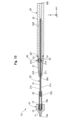
- FIG. 1 is an explanatory diagram illustrating an example of the external configuration of a medical device gripping tool.
- FIG. 1 is an explanatory diagram illustrating an example of the external configuration of a medical device gripping tool.
- FIG. 11 is an explanatory diagram illustrating a cross-sectional configuration of the medical device gripping tool in a second state.
- FIG. 1 is an explanatory diagram illustrating a cross-sectional configuration of a medical device gripping tool in a first state.
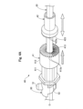
- FIG. 4A and 4B are explanatory diagrams illustrating configurations of a ratchet mechanism and a switching unit.
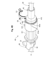
- FIG. 13 is a diagram showing the ratchet mechanism in the ON state.
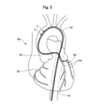
- FIG. 1 shows the state of the heart during the CTO penetration procedure.
- FIG. 1 shows the state of the heart during the CTO penetration procedure.
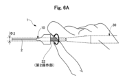
- FIG. 13 is a diagram showing the state of an operator's hands during a CTO penetration procedure.
- FIG. 13 is a diagram showing the state of an operator's hands during a CTO penetration procedure.
- FIG. 13 is an explanatory diagram illustrating a cross-sectional configuration of the medical device gripping tool of the second embodiment with the ratchet mechanism in the ON state.
- FIG. 13 is an explanatory diagram illustrating a cross-sectional configuration of the medical device gripping tool of the second embodiment with the ratchet mechanism in an OFF state.
- 13 is an explanatory diagram illustrating a cross-sectional configuration of a medical device gripping tool of a third embodiment.
- FIG. 13 is an explanatory diagram illustrating a cross-sectional configuration of a medical device gripping tool of a fourth embodiment.
- FIG. 13 is an explanatory diagram illustrating a cross-sectional configuration of a medical device gripping tool of a fifth embodiment.
- FIG. 13 is an explanatory diagram illustrating a cross-
- First Embodiment 1A and 1B are explanatory diagrams illustrating the external configuration of the medical device gripping tool 1.
- FIG. 1A shows the medical device gripping tool 1 in the second state.
- FIG. 1B shows the medical device gripping tool 1 in the first state.
- the medical device gripping tool 1 is attached to the base end side of the medical device 2 and is used to facilitate the rotation, advancement, and retreat of the medical device 2.
- the medical device gripping tool of this embodiment is in the second state shown in FIG. 1A when delivering the medical device 2 to the lesion, and in the first state shown in FIG. 1B when treating the lesion, thereby improving operability and safety, and further improving the efficiency of the procedure. Details will be described later.
- the opening of a CTO using a penetrating guidewire 2 will be described as an example of a specific usage scenario for explaining the medical device holding tool 1.
- the medical device holding tool 1 holds the penetrating guidewire 2 as a medical device and assists the surgeon in manipulating the penetrating guidewire 2.
- the penetrating guidewire 2 is a device for opening a blood vessel by penetrating a lesion that blocks the blood vessel, such as a CTO. Any device, such as a delivery guidewire or a catheter, can be used as the medical device 2.
- the medical device holding tool 1 can be used in all percutaneous procedures using the medical device 2, in addition to opening a CTO.
- FIG. 1 illustrates mutually orthogonal XYZ axes.
- the X axis corresponds to the longitudinal direction of the medical device gripper 1
- the Y axis corresponds to the height direction of the medical device gripper 1
- the Z axis corresponds to the width direction of the medical device gripper 1.
- the left side of FIG. 1 is called the "tip side" of the medical device gripper 1 and each component
- the right side of FIG. 1 is called the "base side” of the medical device gripper 1 and each component.
- the left side of FIG. 1 is the -X axis direction.
- the longitudinal direction of the medical device gripper 1 and each component is the X axis direction.
- the tip and its vicinity are referred to as the "tip portion,” and the base end and its vicinity are referred to as the "base end portion.”
- the tip side is inserted into the living body, and the base end side is operated by a surgeon such as a doctor.
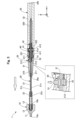
- the medical device gripping tool 1 comprises a gripping section 10, an operating section 20, and a handle section 30.
- the gripping section 10, the operating section 20, and the handle section 30 all have lumens for inserting the penetration guidewire 2 therein. Therefore, during a procedure, the surgeon uses the medical device gripping tool 1 by attaching it to the base end side of the penetration guidewire 2 with the penetration guidewire 2 inserted inside the medical device gripping tool 1.
- the surgeon can switch the medical device gripping tool 1 from the second state shown in FIG. 1A to the first state shown in FIG. 1B by pulling either the gripping section 10 or the operating section 20 in the longitudinal direction while pressing down the switching section 50 provided on the handle section 30. Pulling in the longitudinal direction means moving in the -X axis direction.
- the surgeon can switch the medical device gripper 1 from the first state to the second state by pushing either the gripper 10 or the operating unit 20 in the longitudinal direction while pressing down the switching unit 50. Pushing in the longitudinal direction means moving in the +X-axis direction.
- the operating unit 20 in the first state, has a "first operating unit” and a "second operating unit", and the length of the operating unit 20 is longer than in the second state.
- the outer diameter of the first operating unit is smaller than the outer diameter of the second operating unit.
- the operating unit 20 in the second state, has only the “second operating unit", and the length of the operating unit 20 is shorter than in the first state.
- the first operating unit in the second state, is housed inside the handle unit 30.
- the inside of the handle unit 30 is the housing unit 310, 320.
- the first operating unit corresponds to a "specific part of the operating unit 20".
- the length of the medical device gripping tool 1 changes between the first state and the second state as the length of the operating unit 20 changes. That is, the length of the medical device gripping tool 1 in the first state is longer than the length of the medical device gripping tool 1 in the second state.
- FIG. 2 is an explanatory diagram illustrating the cross-sectional configuration of the medical device gripping tool 1 in the second state.
- the bubble at the bottom of FIG. 2 shows an enlarged view of the vicinity of the gripping portion 10.
- FIG. 3 is an explanatory diagram illustrating the cross-sectional configuration of the medical device gripping tool 1 in the first state.
- the bubble at the bottom of FIG. 3 shows an enlarged view of the vicinity of the switching portion 50.
- the gripping portion 10 is a member that grips and fixes the penetration guidewire 2.
- the gripping portion 10 is disposed at the tip of the medical device gripping tool 1, in other words, at the most distal end of the medical device gripping tool 1.
- the gripping portion 10 has a generally cylindrical shape. Specifically, the outer shape of the tip side of the gripping portion 10 is tapered, and the outer shape of the base end side is cylindrical with a pair of wings extending in the ⁇ Y axis directions. As shown in the bubble in the lower part of Figure 2, a lumen is formed inside the gripping portion 10, connecting the tip opening 10a and the base opening 10b.
- a recess 11 is formed on the inside of the gripping portion 10.
- An inner thread 12 and a protuberance 14 are formed on the inner circumferential surface of the gripping portion 10.
- the recess 11 is located inside the portion of the gripping portion 10 whose outer shape is cylindrical, in other words, on the base end side of the gripping portion 10.
- a part of the tip side of the second shaft 22 of the operating portion 20 and the gripping claw 13 are housed in the recess 11.
- the inner thread 12 is a thread formed on the inner circumferential surface of the gripping portion 10 and is located on the tip side of the recess 11.
- the inner circumferential surface of the gripping portion 10 compresses the claw portion 132 of the gripping claw 13 in the central axial direction, in other words, in the direction of the penetration guide wire 2.
- the protuberance 14 is located inside the portion whose outer shape is tapered, in other words, near the center of the gripping portion 10.
- the raised portion 14 is a portion of the inner circumferential surface of the grip portion 10 that rises toward the center. Between the raised portion 14 and the inner threaded portion 12, a cone-shaped wall portion 110 is formed, with the inner circumferential surface of the grip portion 10 expanding in diameter from the tip side toward the base end side.
- the gripping portion 10 further has a gripping claw 13 for gripping the penetration guide wire 2.
- the gripping claw 13 has a body 131 and multiple claws 132. In the illustrated example, the gripping claw 13 has four claws 132.
- the body 131 is a cylindrical part located on the base end side of the gripping claw 13.
- Each claw 132 is located on the tip side of the gripping claw 13 and is connected to the body 131 on the tip side of the body 131.
- the claws 132 are parts that can move toward the center when compressed from the outside.
- the claws 132 move toward the center by elastic deformation.
- the claws 132 have a thick tip 132a at the tip of the curved plate.
- the tip 132a has a tip wall 130a at its tip side that faces the wall 110, which is part of the inner surface of the gripping portion 10.
- the tip wall 130a is a surface that expands in diameter from the tip side toward the base end side.
- the tip 132a has a base end wall 130b on its base end side that faces the wall 220 of the second shaft 22.
- the base end wall 130b is a surface that contracts in diameter from the tip side toward the base end side.
- the surgeon rotates the gripper 10 around the central axis to screw the inner screw portion 12 into the outer screw portion 222 of the operating portion 20.
- This causes the gripper 10 to move toward the base end, and the gripper claws 13 move toward the base end when pushed by the wall portion 110 of the gripper 10.
- the direction in which the gripper 10 moves is shown by the white arrow in the speech bubble in the lower part of Figure 2.
- the gripper claws 13 move toward the base end and the base end wall portion 130b of the claw portion 132 abuts against the wall portion 220 of the second shaft 22, the gripper claws 13 cannot move any further toward the base end.
- the tip portions 132a of the multiple claws 132 each move toward the center.
- the tip portions 132a of the multiple claw portions 132 can support and fix the penetrating guidewire 2.
- the surgeon simply rotates the gripping portion 10 in the opposite direction.
- the surgeon releases the fixation of the penetrating guidewire 2.
- the surgeon fixes the penetrating guidewire 2.
- the operating section 20 is a member that transmits the operation by the surgeon to the penetration guidewire 2.
- the operating section 20 is connected to the base end side of the gripping section 10 and is disposed closer to the base end than the gripping section 10.
- the operating section 20 is generally long and tubular. As shown in Figures 2 and 3, the operating section 20 has a first shaft 21 and a second shaft 22.
- the first shaft 21 is a cylindrical member (tubular body) having a long outer shape.
- a penetration guidewire 2 is inserted into a lumen 21L inside the first shaft 21.
- a portion of the tip side of the first shaft 21 is inserted into the lumen of the second shaft 22 and is fixed to the second shaft 22, for example, by adhesive.
- a portion of the base side of the first shaft 21 is accommodated in the accommodation portions 310, 320 of the handle portion 30.
- the outer peripheral surface of the first shaft 21 is provided with two groove portions 211, 212 in which the outer peripheral surface of the shaft is recessed in an annular shape.
- the recess on the tip side is also called the tip groove portion 211, and the recess on the base side is also called the base groove portion 212. As shown in FIG.
- the second state is a state in which the distal groove 211 and the engagement portion 52 of the switching portion 50 are engaged with each other.
- the first state is a state in which the proximal groove 212 and the engagement portion 52 of the switching portion 50 are engaged with each other.
- relative rotation of the operating unit 20 with respect to the handle unit 30 is not restricted in the circumferential direction of the medical device gripper 1. As shown in the balloon in the lower part of Figure 3, when the knob 51 of the switching unit 50 is pressed down, the grooves 211 and 212 disengage from the engagement unit 52, making it possible to switch between the first state and the second state.
- the second shaft 22 is a cylindrical member.
- the second shaft 22 has a larger outer diameter than the first shaft 21 and a larger inner diameter than the first shaft 21, and a portion of the tip side of the first shaft 21 is inserted into and fixed in a lumen within the second shaft 22.
- the second shaft 22 covers a portion of the tip side of the first shaft 21 exposed from the tip of the handle portion 30.
- a wall portion 220 and an outer thread portion 222 are formed on the outer circumferential surface of the tip portion of the second shaft 22.
- a portion of the tip side of the second shaft 22 is housed in the recess 11 of the grip portion 10.
- the handle portion 30 is a member that supports the operating portion 20 in a relatively rotatable state and enables the surgeon to grasp the medical device gripping tool 1.
- the handle portion 30 is provided on the base end side of the operating portion 20.
- the handle portion 30 is disposed at the base end of the medical device gripping tool 1, in other words, at the most base end side of the medical device gripping tool 1.
- the handle portion 30 is generally long and tubular. As shown in Figures 2 and 3, the handle portion 30 has a tip housing 31, a base housing 32, a ratchet mechanism 40, and a switching portion 50.
- the tip housing 31 is a cylindrical member in which both the outer diameter and the inner diameter gradually decrease from the base end side to the tip end side.
- the tip housing 31 is disposed on the tip side of the base end housing 32.
- a tip housing 310 is formed inside the tip housing 31.
- the tip housing 310 is a space for housing the first shaft 21 and the switching unit 50.
- a tip opening 30a that connects the tip housing 310 to the outside is formed on the tip surface of the tip housing 31, and a part of the base end side of the first shaft 21 is inserted from the tip opening 30a to the tip housing 310.
- An engagement part 311 is formed on the base end of the tip housing 31 to fix the tip housing 31 and the base end housing 32.
- a recess 312 that is recessed in the outer circumferential surface is formed on a part of the outer circumferential surface of the tip housing 31, and a knob 51 of the switching unit 50 protrudes from a through hole provided in the center of the recess 312.
- the through hole provided in the center of the recess 312 is a hole that connects the outside to the tip storage section 310.
- the base end housing 32 is a cylindrical member having a substantially constant outer diameter.
- the base end housing 32 is disposed closer to the base end than the tip housing 31.
- a base end accommodating section 320 is formed inside the base end housing 32.
- the base end accommodating section 320 is a space for accommodating the first shaft 21 and the ratchet mechanism 40.
- An engagement section 321 is formed at the tip of the base end housing 32 for fixing the tip housing 31 and the base end housing 32.
- a base end opening 30b is formed at the base end surface of the base end housing 32, connecting the base end accommodating section 320 to the outside, and the penetration guidewire 2 inserted into the medical device gripping tool 1 is pulled out to the outside from the base end opening 30b.
- the switching unit 50 is a member for switching the fixed state of the first shaft 21 to enable switching between a first state and a second state.
- the switching unit 50 is accommodated in the tip accommodation unit 310 of the tip housing 31.
- the switching unit 50 has a knob 51 and an engagement unit 52.
- the knob 51 is a protrusion provided on the surface opposite to the engagement unit 52. As shown in FIGS. 2 and 3, the upper part of the knob 51 is exposed to the outside from the through hole of the recess 312 of the tip housing 31.
- the engagement unit 52 is a claw for engaging with the grooves 211 and 212 of the first shaft 21. As shown in FIGS.
- the engagement unit 52 engages with the grooves 211 and 212 when the knob 51 is not pressed down.
- the engagement portion 52 is separated from the grooves 211, 212 and does not engage with the grooves 211, 212. Therefore, when the knob 51 is pressed down, the first shaft 21 is released from the fixed state, and the first shaft 21 can be moved. In other words, when the knob 51 is pressed down, the first state and the second state can be changed.
- the ratchet mechanism 40 is a mechanism for restricting the rotation direction of the operating unit 20 relative to the handle unit 30.
- the ratchet mechanism 40 is housed in the base end housing 320 of the base end housing 32.
- the ratchet mechanism 40 has a first ratchet 41 and a second ratchet 42.
- the first ratchet 41 has an axle body 411 arranged at the tip side, a gear body 412 arranged at the base end side, and a spring 414 (see FIG. 2 and FIG. 3) built into the inside of the axle body 411 and the gear body 412.
- the axle body 411 is a hollow polygonal column-shaped member, and is fixed to the tip housing 31, for example, by adhesive, with the first shaft 21 inserted therethrough.
- the base end of the axle body 411 is housed inside the gear body 412.
- the gear body 412 is a bottomed cylindrical member, and is housed inside the base housing 32 with the first shaft 21 inserted therethrough.
- the inner diameter of the tip of the gear body 412 is slightly larger than the outer diameter of the base end of the axle body 411, and the tip of the gear body 412 covers the base end of the axle body 411.
- the tip of the gear body 412 is an open end. Therefore, when the gear body 412 tries to rotate in the circumferential direction, the outer peripheral surface of the shaft body 411 and the inner peripheral surface of the gear body 412 hook each other, so that the shaft body 411 restricts the rotation of the gear body 412 in the circumferential direction.
- the gear body 412 has sawtooth teeth 413 on the outside of the base end surface corresponding to the bottom.
- the teeth 413 of the gear body 412 are arranged on a plane perpendicular to the rotation axis O with respect to the handle part 30 of the operation part 20.
- the spring 414 is housed inside the shaft body 411 and the gear body 412, and presses the gear body 412 toward the second ratchet 42.
- the direction in which the spring 414 presses is shown by the diagonal arrow in FIG. 4A.
- the base end surface of the gear body 412 engages with the step part 322 of the base end housing 32, so that even if it is pressed by the spring 414, it does not move toward the base end side from the position in FIG. 3.
- the second ratchet 42 is a cylindrical member with a bottom, and has sawtooth teeth 423 on the outside of the tip surface corresponding to the bottom. In other words, the teeth 423 of the second ratchet 42 are arranged on a plane perpendicular to the rotation axis O relative to the handle portion 30 of the operating unit 20.
- the second ratchet 42 is fixed to the first shaft 21 with the first shaft 21 inserted inside. As shown in Figure 2, when the medical device gripping tool 1 is in the second state, the second ratchet 42 is located away from the first ratchet 41. As shown in Figure 3, when the medical device gripping tool 1 is in the first state, the second ratchet 42 is located adjacent to the first ratchet 41.
- the ratchet mechanism 40 When the first and second ratchets 41, 42 are in separate positions, this is also referred to as “the ratchet mechanism 40 is in the OFF state," and when the first and second ratchets 41, 42 are in adjacent positions, this is also referred to as “the ratchet mechanism 40 is in the ON state.” That is, when the medical device gripping tool 1 is in the second state (FIG. 2), the ratchet mechanism 40 is in the OFF state. When the medical device gripping tool 1 is in the first state (FIG. 3), the ratchet mechanism 40 is in the ON state.
- FIG. 4B is a diagram showing the ratchet mechanism 40 in the ON state.
- the teeth 423 of the second ratchet 42 engage with the teeth 413 of the gear body 412 of the first ratchet 41.
- the wall portion 413a of the sawtooth tooth 413 and the wall portion 423a of the tooth 423 are caught, thereby restricting the relative rotation of the operating unit 20 in the second direction D2 with respect to the handle unit 30.
- the manner in which the relative rotation is restricted is shown by the dashed arrow in FIG. 4B.
- the ratchet mechanism 40 is in the ON state, the relative rotation in the first direction D1 opposite to the second direction D2 is not restricted.
- the ratchet mechanism 40 when the ratchet mechanism 40 is in the ON state, the relative rotation in the first direction D1 is permitted. This is because the walls 413a and 423a of the teeth 413 and 423 do not exist on the side rotating in the first direction D1.
- the gear body 412 of the first ratchet 41 is pressed toward the second ratchet 42 by the spring 414, so that the first ratchet 41 and the second ratchet 42 are prevented from coming apart as the operating unit 20 rotates in the first direction D1 or the second direction D2.
- the gripping portion 10, the operating portion 20, and the handle portion 30 can be made of a known resin material.
- the gripping portion 10, the operating portion 20, and the handle portion 30 can be made of the same material or different materials.
- the gripping claws 13 can be made of a known metal material.
- Fig. 5 is a diagram showing the state of the heart during a CTO penetration procedure.
- a case where a CTO 99 in a left coronary artery 94 of a heart 90 is opened is illustrated.
- the penetration guidewire 2 is drawn with a solid line and the guiding catheter 3 is drawn with a dashed line.
- the surgeon can perform the procedure, for example, according to the following steps a1 to a5. (a1)
- the surgeon inserts a work horse wire from the forearm or thigh, and delivers it to the entrance of the left coronary artery 94.
- the work horse wire is a guide wire for delivery.
- the surgeon inserts a work horse wire into the tip of the guiding catheter 3 and delivers the guiding catheter 3 along the work horse wire to the entrance of the left coronary artery 94.
- the surgeon removes the workpiece wire and inserts the penetrating guide wire 2 from the proximal end of the guiding catheter 3.
- the surgeon pushes the penetrating guide wire 2 along the guiding catheter 3 to deliver the penetrating guide wire 2 to the entrance of the left coronary artery 94.
- the surgeon further advances the penetrating guidewire 2 into the left coronary artery 94, and delivers the penetrating guidewire 2 to the branch of the left coronary artery 94 in which the CTO 99 is located.
- the surgeon penetrates the CTO 99 using the penetration guide wire 2.
- FIG. 6A and 6B are diagrams showing the state of the operator's hands during the CTO penetration procedure.
- FIG. 6A shows the operation in the second state
- FIG. 6B shows the operation in the first state.
- step a4 for example, when an operation is required to push the penetrating guidewire 2 in the intended direction at a branching part of a blood vessel or an operation is required to push the penetrating guidewire 2 into a part of a blood vessel where the blood vessel is sharply curved, the operator attaches the medical device holder 1 to the penetrating guidewire 2, sets the medical device holder 1 to the second state shown in FIG. 6A, and operates the second operation part.
- the outer diameter ⁇ 2 of the second operation part operated at this time is relatively larger than the outer diameter ⁇ 1 of the first operation part. This allows the operator to perform delicate rotation operation, in other words, highly accurate rotation operation, on the penetrating guidewire 2, and easily performs delivery operations that require sharp curvatures or complex blood vessel selection.
- the operation of pushing the penetrating guidewire 2 into a part of a blood vessel where the blood vessel is sharply curved is, in other words, a delicate operation of the penetrating guidewire 2.
- the relative rotation of the operating section 20 with respect to the handle section 30 is not restricted, so the surgeon can rotate the penetration guidewire 2 in both the first direction D1 and the second direction D2, allowing unhindered blood vessel selection.
- step a5 the surgeon places the medical device gripper 1 in the first state shown in FIG. 6B and operates the first operating part.
- the outer diameter ⁇ 1 of the first operating part operated at this time is relatively smaller than the outer diameter ⁇ 2 of the second operating part. This allows the surgeon to apply more rotations to the penetration guidewire 2. In other words, the movement of the fingers required to rotate the penetration guidewire 2 by a certain angle can be made smaller, making it easier to penetrate the hard CTO 99.
- the relative rotation of the operation part 20 in the second direction D2 with respect to the handle part 30 is limited, so that even if the surgeon receives a reaction force from the CTO 99 when rotating the operation part 20 in the first direction D1, the penetration guidewire 2 is prevented from rotating in the second direction D2, which may cause damage to the body cavity.
- steps a1 to a3 the surgeon performs the operation without attaching the medical device gripper 1 to the work horse wire or the penetrating guide wire 2.
- steps a1 to a3 the surgeon may perform the operation by attaching the medical device gripper 1 to the work horse wire or the penetrating guide wire 2.
- steps a3 to a5 the surgeon may use another device to suppress kinking of the penetrating guide wire 2. Examples of other devices to suppress kinking of the penetrating guide wire 2 include a short catheter and a protective shaft.
- the protuberance 14 is provided on the inside of the gripper 10 provided at the tip, so that when the protective shaft is inserted from the tip opening 10a, the proximal end of the protective shaft can be supported by the protuberance 14.
- the second operating part in the second state, the second operating part is adjacent to the handle part 30, while in the first state, the first operating part is adjacent to the handle part 30. Therefore, the surgeon does not need to move the position of the hand holding the medical device holder 1 in both the operation in the second state for finely delivering the penetration guidewire 2 and the operation in the first state for penetrating the CTO 99. This improves the operability of the medical device holder 1 and improves the efficiency of the procedure. Since the shape of the medical device holder 1 changes at a glance between the first and second states, the surgeon can easily distinguish the state and misuse can be suppressed.
- the surgeon can easily rotate the medical device by gripping the handle portion 30 with his or her hand and rotating the outer periphery of the operating portion 20 with his or her fingers. Therefore, for example, when penetrating a CTO 99 using a penetrating guidewire 2 as a medical device, even if the penetrating guidewire 2 receives a reaction force from the CTO 99, it is easy to resist the reaction force. As a result, the operability and safety of the medical device gripping tool 1 can be improved.
- the medical device gripping tool 1 of the first embodiment is configured to be switchable between a first state in which a specific part of the operating part 20 protrudes from the housing part 310, 320 of the handle part 30, and a second state in which the specific part is housed in the housing part 310, 320 of the handle part 30. Therefore, by changing the structure of the outer periphery 21c, 22c for the specific part of the operating part 20 and the other parts, the surgeon can change the structure of the outer periphery 21c, 22c of the operating part 20 to a structure suitable for the surgeon's operation, such as setting the second state when delivering the penetrating guide wire 2 as a medical device and setting the first state when penetrating the CTO 99.
- the structure of the outer periphery 21c, 22c may be, for example, the outer diameter in the above embodiment, or the presence or absence of anti-slip processing. As a result, the operability and safety of the medical device gripping tool 1 can be further improved. The surgeon can easily switch between the first state and the second state by sliding the operating part 20.
- the handle portion 30 further includes a ratchet mechanism 40 that, when in the ON state, allows relative rotation of the operating portion 20 with respect to the handle portion 30 in the first direction D1 and restricts relative rotation in the second direction D2 opposite to the first direction D1 (FIGS. 4A and 4B). Therefore, by turning the ratchet mechanism 40 to the ON state, when the surgeon rotates the penetration guidewire 2 in the first direction D1 to penetrate the CTO, the penetration guidewire 2 can be prevented from rotating in the second direction D2 due to the reaction force from the CTO 99. As a result, the operability and safety of the medical device gripping tool 1 can be further improved, and the efficiency of CTO penetration using the penetration guidewire 2 can be improved.
- the ratchet mechanism 40 when in the first state for CTO penetration, the ratchet mechanism 40 is in the ON state, so that when the surgeon rotates the penetration guidewire 2 in the first direction D1 for CTO penetration, the penetration guidewire 2 can be prevented from rotating in the second direction D2 due to the reaction force from the CTO 99.
- the medical device gripping tool 1 is in the second state for delivering the penetration guidewire 2
- the ratchet mechanism 40 is in the OFF state, so that the rotation operation in the first and second directions D1 and D2 for advancing the penetration guidewire 2 to the target branch at the branching part of the blood vessel is not hindered.
- the operability and safety of the medical device gripping tool 1 can be further improved, and further, the efficiency of CTO penetration using the penetration guidewire 2 can be improved.
- the ratchet mechanism 40 is realized by the first ratchet 41 and the second ratchet 42, each of which has teeth 413, 423 arranged on a plane perpendicular to the rotation axis O relative to the handle portion 30 of the operating portion 20. Therefore, in the ON state, the teeth 413, 423 of the first and second ratchets 41, 42 reliably mesh with each other, and in the OFF state, the teeth 413, 423 of the first and second ratchets 41, 42 can be reliably released.
- the outer diameter ⁇ 1 of the first operation part corresponding to a specific part in the operation part 20 is smaller than the outer diameter ⁇ 2 of the second operation part.
- the outer diameter ⁇ 1 of the first operation part can also be said to be the outer diameter of the outer periphery 21c of the first shaft 21.
- the outer diameter ⁇ 2 of the second operation part can also be said to be the outer diameter of the outer periphery 22c of the second shaft 22. Therefore, when the medical device gripping tool 1 is in the first state for penetrating the CTO, the surgeon can apply more rotation to the penetration guidewire 2 by operating the first operation part having a relatively small outer diameter.
- the finger movement for rotating the penetration guidewire 2 by a certain angle can be made smaller than when the second operation part is used.
- the surgeon can apply more precise operation to the penetration guidewire 2 by operating the second operation part having a relatively large outer diameter.
- the operability and safety of the medical device gripping tool 1 can be further improved, and the efficiency of CTO penetration using the penetration guidewire 2 can be further improved.
- Fig. 7 is an explanatory diagram illustrating a cross-sectional configuration of the medical device gripping tool 1A of the second embodiment when the ratchet mechanism 40A is in the ON state.
- Fig. 8 is an explanatory diagram illustrating a cross-sectional configuration of the medical device gripping tool 1A of the second embodiment when the ratchet mechanism 40A is in the OFF state.
- the medical device gripping tool 1A of the second embodiment does not have an extension mechanism.
- the medical device gripping tool 1A has an operation unit 20A instead of the operation unit 20, a handle unit 30A instead of the handle unit 30, a ratchet mechanism 40A instead of the ratchet mechanism 40, and a fixing unit 50A instead of the switching unit 50 in the configuration described in the first embodiment.
- the operating unit 20A has a first shaft 21A instead of the first shaft 21.
- the first shaft 21A differs from the first embodiment only in that it does not have a tip groove portion 211.
- the handle unit 30A has a tip housing 31A instead of the tip housing 31, and a base housing 32A instead of the base housing 32.
- the tip housing 31A differs from the first embodiment only in that it does not have a recess 312.
- the base housing 32A has a cutout portion.
- the cutout portion is a linear cutout provided on the side surface of the base housing 32A in the +Y axis direction, and is a cutout that communicates between the base housing 320 and the outside.
- the ratchet mechanism 40A has a second ratchet 42A instead of the second ratchet 42.
- the second ratchet 42A is not fixed to the first shaft 21A and can slide on the outer circumferential surface of the first shaft 21A along the longitudinal direction of the first shaft 21.
- a handle 421 is also attached to the second ratchet 42A.
- the handle 421 protrudes outward from a notch in the base housing 32A. The surgeon can grip the handle 421 and move it along the notch in the base housing 32A to switch the ratchet mechanism 40A between the ON state (FIG. 7) and the OFF state (FIG. 8).
- the fixing part 50A fixes the first shaft 21A by engaging the engagement part 52 with the base end groove 212 of the first shaft 21A.
- the fixing part 50A and the base end groove 212 may be omitted, and the first shaft 21A and the handle part 30A may be fixed with an adhesive or the like.
- the configuration of the medical device gripping tool 1A can be modified in various ways, and it may be configured without an extension mechanism, in other words, a configuration that does not switch between the first and second states.
- a medical device gripping tool 1A of the second embodiment the same effects as those of the first embodiment can be achieved.
- the configuration of the medical device gripping tool 1A can be simplified, and the surgeon can operate the first operating part or the second operating part that is more suitable for the surgeon's operation, thereby improving the operability and safety of the medical device gripping tool and improving the efficiency of CTO penetration using the penetration guidewire 2.
- Third Embodiment 9 is an explanatory diagram illustrating a cross-sectional configuration of a medical device holder 1B of the third embodiment.
- the medical device holder 1B of the third embodiment does not have an extension mechanism like the second embodiment, and the structures of the first and second operating parts are different from those of the second embodiment.
- the medical device holder 1B of the third embodiment has an operating part 20B instead of the operating part 20A in the configuration described in the second embodiment.
- the operating unit 20B includes the first shaft 21A described in the second embodiment.
- the operating unit 20B further includes a second shaft 22B instead of the second shaft 22, and includes a non-slip surface 25.
- the second shaft 22B is longer than the second shaft 22 described in the first embodiment, and covers the entire first shaft 21A exposed from the tip of the handle portion 30A.
- the non-slip surface 25 is provided on a portion of the outer circumferential surface of the base end side of the second shaft 22B. In the illustrated example, the non-slip surface 25 is provided on approximately half of the outer circumferential surface of the base end side of the second shaft 22B.
- the non-slip surface 25 may be a coating made of a resin with a high friction coefficient, or unevenness provided on the outer circumferential surface.
- the outer circumferential portion 22c of the second shaft 22B that is not covered by the non-slip surface 25 corresponds to the "second operating unit”
- the outer circumferential portion 25c of the non-slip surface 25 corresponds to the "first operating unit”. Because the anti-slip surface 25 is sufficiently thin, in this embodiment, the first operating portion and the second operating portion can be considered to have the same outer diameter.
- the anti-slip surface 25 is depicted in FIG. 9 as being thicker than it actually is.
- the configuration of the medical device gripper 1B can be modified in various ways, and it may not have an extension mechanism, and the first operating part and the second operating part may have the same outer diameter.
- this third embodiment of the medical device gripper 1B it is possible to achieve the same effects as the first and second embodiments.
- Fourth Embodiment Fig. 10 is an explanatory diagram illustrating a cross-sectional configuration of a medical device gripping tool 1C of the fourth embodiment.
- the medical device gripping tool 1C of the fourth embodiment does not have a ratchet mechanism 40 in the configuration described in the first embodiment.
- the medical device gripping tool 1C can be used by switching between a first state shown in Fig. 10 and a second state as shown in Fig. 2. Since the medical device gripping tool 1C does not have a ratchet mechanism 40, the rotation direction of the operating part 20 is not limited even in the first state.
- the configuration of the medical device gripping tool 1C can be modified in various ways, and it may be configured without the ratchet mechanism 40.
- a medical device gripping tool 1C of the fourth embodiment the same effects as those of the first embodiment can be achieved.
- the configuration of the medical device gripping tool 1C can be simplified, and rotation can be applied in both the first direction D1 and the second direction D2 when penetrating the CTO, improving the freedom of the procedure.
- Fifth Embodiment 11 is an explanatory diagram illustrating a cross-sectional configuration of a medical device gripping tool 1D of the fifth embodiment.
- the medical device gripping tool 1D of the fifth embodiment does not have both an extension mechanism and a ratchet mechanism 40.
- the medical device gripping tool 1D does not have the ratchet mechanism 40 in the configuration described in the first embodiment, and has an operation part 20D instead of the operation part 20, a handle part 30D instead of the handle part 30, and a fixing part 50D instead of the switching part 50.
- the operating unit 20D has a first shaft 21D instead of the first shaft 21.
- the first shaft 21D differs from the first embodiment only in that it does not have a tip groove 211.
- the handle unit 30D has a tip housing 31D instead of the tip housing 31.
- the tip housing 31D differs from the first embodiment only in that it does not have a recess 312.
- the fixing unit 50D fixes the first shaft 21D by engaging the engagement unit 52 with the base groove 212 of the first shaft 21D.
- the fixing unit 50D and the base groove 212 may be omitted, and the first shaft 21D and the handle unit 30D may be fixed with an adhesive or the like.
- the configuration of the medical device gripping tool 1D can be modified in various ways, and it may be configured to have neither the telescopic mechanism nor the ratchet mechanism 40.
- the medical device gripping tool 1D of the fifth embodiment can also achieve the same effects as the first embodiment.
- the configuration of the medical device gripping tool 1D can be simplified, and rotation can be applied in both the first direction D1 and the second direction D2 when penetrating the CTO, improving the freedom of the procedure.
- the medical device gripping tool 1 may omit some of the above-mentioned configurations, or may include additional configurations not described above.
- the outer shape of the gripping portion 10 and the handle portion 30 may be changed to a shape that is more suitable for operation by the surgeon.
- the outer peripheral surface of the handle portion 30 may be provided with an anti-slip material to make it easier for the surgeon to grip.
- the anti-slip material can be achieved by a coating, unevenness, etc.
- the distal housing 31 and the proximal housing 32 may be formed integrally.
- the medical device gripping tool 1 may be configured to be switchable between the first state and the second state without operating the switching unit 50.
- the switching unit 50 and the distal groove portion 211 and the proximal groove portion 212 of the first shaft 21 may be omitted.
- the surgeon can quickly switch the medical device gripping tool 1 to the first state by pulling either the gripping unit 10 or the operating unit 20 in the longitudinal direction, and can quickly switch the medical device gripping tool 1 to the second state by pushing either the gripping unit 10 or the operating unit 20 in the longitudinal direction.
- the configuration of the ratchet mechanism 40 is one example, and various modifications are possible.
- the teeth 413, 423 of the first and second ratchets 41, 42 do not have to be arranged on a plane perpendicular to the rotation axis O relative to the handle portion 30 of the operating unit 20.
- the first and second ratchets 41, 42 may be realized by sawtooth teeth arranged in the circumferential direction and pawls that catch on the teeth, similar to a normal ratchet mechanism.
- the shaft 411 and the spring 414 may be omitted, and the shaft 411 may be used to restrict the rotation of the first ratchet 41, and the spring 414 may be used to push the first ratchet 41, by other means.
- the configuration of the switching unit 50 is one example, and various modifications are possible.
- the engagement portion 52 (protrusion) of the switching unit 50 is engaged with the grooves 211, 212 formed in the first shaft 21.
- the convex-concave relationship may be reversed.
- a protrusion may be formed on the first shaft 21, and engaged with the groove of the switching unit 50 to fix it in place.
Landscapes
- Health & Medical Sciences (AREA)
- Life Sciences & Earth Sciences (AREA)
- Biophysics (AREA)
- Pulmonology (AREA)
- Engineering & Computer Science (AREA)
- Anesthesiology (AREA)
- Biomedical Technology (AREA)
- Heart & Thoracic Surgery (AREA)
- Hematology (AREA)
- Animal Behavior & Ethology (AREA)
- General Health & Medical Sciences (AREA)
- Public Health (AREA)
- Veterinary Medicine (AREA)
- Surgical Instruments (AREA)
Abstract
医療デバイス把持具は、医療デバイスを把持する把持部と、把持部の基端側に接続され、把持部に把持された医療デバイスが挿入されるルーメンを有する筒形状の操作部であって、術者が回転操作を行うための外周部を有し、外周部が術者から受けた回転力を、把持部を介して医療デバイスに伝達する操作部と、操作部の基端側に設けられ、操作部を相対回転可能な状態で支持するハンドル部であって、操作部の基端側の一部を収容する収容部を有するハンドル部と、を備える。
Description
本開示は、医療デバイス把持具に関する。
例えば、特許文献1,2には、ガイドワイヤを把持すると共に、ガイドワイヤの回転、前進及び後退を行いやすくするために用いられるガイドワイヤ把持具が開示されている。
慢性完全閉塞(CTO)のように、血管内が病変によって閉塞されてしまう場合がある。このような病変を治療する手技の1つとして、貫通用ガイドワイヤを用いたCTOの貫通が知られている。貫通用ガイドワイヤでCTOを貫通するためには、貫通用ガイドワイヤに、デリバリのときよりも多くの回転量を加える必要があると共に、CTOからの反力に対抗する必要がある。この点、特許文献1,2に記載のガイドワイヤ把持具では、貫通用ガイドワイヤを用いたCTO貫通時の上記課題について何ら考慮されておらず、操作性と安全性において改善の余地があった。
このような課題は、貫通用ガイドワイヤを用いたCTOの貫通に限らず、ガイドワイヤ及びカテーテルといった医療デバイスを用いた経皮的手技の全般に共通する。このような課題は、血管系に限らず、リンパ腺系、胆道系、尿路系、気道系、消化器官系、分泌腺及び生殖器官といった、生体管腔内に挿入される医療デバイスの全般に共通する。
本開示は、上述の課題の少なくとも一部を解決するためになされたものであり、以下の形態として実現することが可能である。
(1)本開示の一形態によれば、医療デバイス把持具が提供される。この医療デバイス把持具は、前記医療デバイスを把持する把持部と、前記把持部の基端側に接続され、前記把持部に把持された前記医療デバイスが挿入されるルーメンを有する筒形状の操作部であって、術者が回転操作を行うための外周部を有し、前記外周部が術者から受けた回転力を、前記把持部を介して前記医療デバイスに伝達する操作部と、前記操作部の基端側に設けられ、前記操作部を相対回転可能な状態で支持するハンドル部であって、前記操作部の基端側の一部を収容する収容部を有するハンドル部と、を備える。
この構成によれば、術者は、ハンドル部を手で握りつつ操作部の外周部を指で回転させることで、容易に、医療デバイスに回転操作を加えることができる。このため、例えば、医療デバイスとして貫通用ガイドワイヤを用いてCTOの貫通を行う場合に、貫通用ガイドワイヤがCTOからの反力を受けた場合であっても、反力に抵抗しやすい。この結果、医療デバイス把持具の操作性と安全性とを向上できる。
(2)上記形態の医療デバイス把持具において、前記収容部に収容される前記操作部の長さは変更可能であり、前記医療デバイス把持具は、前記操作部のうちの特定の部分が、前記ハンドル部の前記収容部から突出した第1状態と、前記特定の部分が、前記ハンドル部の前記収容部に収容された第2状態と、を切り替え可能であってもよい。
この構成によれば、医療デバイス把持具は、操作部のうちの特定の部分がハンドル部の収容部から突出した第1状態と、特定の部分がハンドル部の収容部に収容された第2状態と、を切り替え可能である。このため、操作部のうちの特定の部分と、それ以外の部分と、について外周部の構造を変化させることによって、術者は、医療デバイスをデリバリする際には第2状態とし、CTO貫通時には第1状態とするというように、操作部の外周部の構造を、術者の操作に適した構造に変化させることができる。外周部の構造とは、例えば、外径、滑り止め加工有無等である。この結果、医療デバイス把持具の操作性と安全性とをより一層向上できる。術者は、操作部をスライド移動させることで、簡単に、第1状態と第2状態を切り替えることができる。
この構成によれば、医療デバイス把持具は、操作部のうちの特定の部分がハンドル部の収容部から突出した第1状態と、特定の部分がハンドル部の収容部に収容された第2状態と、を切り替え可能である。このため、操作部のうちの特定の部分と、それ以外の部分と、について外周部の構造を変化させることによって、術者は、医療デバイスをデリバリする際には第2状態とし、CTO貫通時には第1状態とするというように、操作部の外周部の構造を、術者の操作に適した構造に変化させることができる。外周部の構造とは、例えば、外径、滑り止め加工有無等である。この結果、医療デバイス把持具の操作性と安全性とをより一層向上できる。術者は、操作部をスライド移動させることで、簡単に、第1状態と第2状態を切り替えることができる。
(3)上記形態の医療デバイス把持具において、前記ハンドル部は、さらに、ラチェット機構を有し、ON状態の前記ラチェット機構は、前記操作部の前記ハンドル部に対する第1方向への相対回転を許容し、前記第1方向とは反対の第2方向への相対回転を制限し、OFF状態の前記ラチェット機構は、前記第1方向への相対回転と、前記第2方向への相対回転の両方を許容してもよい。
この構成によれば、ハンドル部はさらに、ON状態のとき、操作部のハンドル部に対する第1方向への相対回転を許容し、第1方向とは反対の第2方向への相対回転を制限するラチェット機構を備える。このため、ラチェット機構をON状態とすることによって、術者がCTO貫通のために医療デバイスを第1方向に回転させた際に、CTOからの反力によって医療デバイスが第2方向へ逆回転することを抑制できる。この結果、医療デバイス把持具の操作性と安全性とをより一層向上でき、さらに、医療デバイスを用いたCTO貫通の効率を向上できる。
この構成によれば、ハンドル部はさらに、ON状態のとき、操作部のハンドル部に対する第1方向への相対回転を許容し、第1方向とは反対の第2方向への相対回転を制限するラチェット機構を備える。このため、ラチェット機構をON状態とすることによって、術者がCTO貫通のために医療デバイスを第1方向に回転させた際に、CTOからの反力によって医療デバイスが第2方向へ逆回転することを抑制できる。この結果、医療デバイス把持具の操作性と安全性とをより一層向上でき、さらに、医療デバイスを用いたCTO貫通の効率を向上できる。
(4)上記形態の医療デバイス把持具において、前記ハンドル部は、さらに、ラチェット機構を有し、前記医療デバイス把持具が前記第1状態のときに、前記ラチェット機構がON状態となり、前記ラチェット機構は、前記操作部の前記ハンドル部に対する第1方向への相対回転を許容し、前記第1方向とは反対の第2方向への相対回転を制限し、前記医療デバイス把持具が前記第2状態のときに、前記ラチェット機構がOFF状態となり、前記ラチェット機構は、前記第1方向への相対回転と、前記第2方向への相対回転の両方を許容してもよい。
この構成によれば、医療デバイス把持具がCTO貫通のための第1状態のときに、ラチェット機構がON状態となるため、術者がCTO貫通のために医療デバイスを第1方向に回転させた際に、CTOからの反力によって医療デバイスが第2方向へ逆回転することを抑制できる。医療デバイス把持具が医療デバイスをデリバリするための第2状態のときに、ラチェット機構がOFF状態となるため、医療デバイスを血管の分岐部において目的の枝に進ませるための第1,2方向への回転操作を妨げない。この結果、医療デバイス把持具の操作性と安全性とをより一層向上でき、さらに、医療デバイスを用いたCTO貫通の効率を向上できる。
この構成によれば、医療デバイス把持具がCTO貫通のための第1状態のときに、ラチェット機構がON状態となるため、術者がCTO貫通のために医療デバイスを第1方向に回転させた際に、CTOからの反力によって医療デバイスが第2方向へ逆回転することを抑制できる。医療デバイス把持具が医療デバイスをデリバリするための第2状態のときに、ラチェット機構がOFF状態となるため、医療デバイスを血管の分岐部において目的の枝に進ませるための第1,2方向への回転操作を妨げない。この結果、医療デバイス把持具の操作性と安全性とをより一層向上でき、さらに、医療デバイスを用いたCTO貫通の効率を向上できる。
(5)上記形態の医療デバイス把持具において、前記ラチェット機構は、前記操作部の前記ハンドル部に対する回転軸に対して、垂直な面に配置された歯を有する第1ラチェットと、前記操作部の前記ハンドル部に対する回転軸に対して、垂直な面に配置された歯を有する第2ラチェットとを有し、前記ON状態のとき、前記第1ラチェットの歯に対して前記第2ラチェットの歯が係合することで、前記操作部の前記ハンドル部に対する前記第2方向への相対回転を制限し、前記OFF状態のとき、前記第1ラチェットの歯と前記第2ラチェットの歯とが離れることで、前記操作部の前記ハンドル部に対する相対回転を制限しなくてもよい。
この構成によれば、ラチェット機構は、操作部のハンドル部に対する回転軸に対して、垂直な面に配置された歯をそれぞれ有する第1ラチェットと第2ラチェットとにより実現されているため、ON状態において第1,2ラチェットの歯が確実に噛み合い、OFF状態において第1,2ラチェットの歯を確実に開放できる。
この構成によれば、ラチェット機構は、操作部のハンドル部に対する回転軸に対して、垂直な面に配置された歯をそれぞれ有する第1ラチェットと第2ラチェットとにより実現されているため、ON状態において第1,2ラチェットの歯が確実に噛み合い、OFF状態において第1,2ラチェットの歯を確実に開放できる。
(6)上記形態の医療デバイス把持具において、前記操作部は、前記特定の部分に対応する第1操作部と、残余の部分に対応する第2操作部とを有し、前記第1操作部の外径は、前記第2操作部の外径よりも小さくてもよい。
この構成によれば、操作部において、特定の部分に対応する第1操作部の外径は、第2操作部の外径よりも小さい。このため、医療デバイス把持具がCTO貫通のための第1状態のときには、術者は、外径が相対的に小さい第1操作部を操作することで、医療デバイスに対してより多くの回転を加えることができる。換言すれば、第1操作部では、医療デバイスをある一定の角度だけ回転させるための指の動きを、第2操作部を用いる場合と比べて小さくできる。医療デバイス把持具が医療デバイスをデリバリするための第2状態のときには、術者は、外径が相対的に大きい第2操作部を操作することで、医療デバイスに対してより精度の高い操作を加えることができる。この結果、医療デバイス把持具の操作性と安全性とをより一層向上でき、さらに、医療デバイスを用いたCTO貫通の効率をより一層向上できる。
この構成によれば、操作部において、特定の部分に対応する第1操作部の外径は、第2操作部の外径よりも小さい。このため、医療デバイス把持具がCTO貫通のための第1状態のときには、術者は、外径が相対的に小さい第1操作部を操作することで、医療デバイスに対してより多くの回転を加えることができる。換言すれば、第1操作部では、医療デバイスをある一定の角度だけ回転させるための指の動きを、第2操作部を用いる場合と比べて小さくできる。医療デバイス把持具が医療デバイスをデリバリするための第2状態のときには、術者は、外径が相対的に大きい第2操作部を操作することで、医療デバイスに対してより精度の高い操作を加えることができる。この結果、医療デバイス把持具の操作性と安全性とをより一層向上でき、さらに、医療デバイスを用いたCTO貫通の効率をより一層向上できる。
(7)上記形態の医療デバイス把持具において、前記操作部は、前記特定の部分に対応する第1操作部と、残余の部分に対応する第2操作部とを有し、前記第2操作部は、前記第1操作部よりも先端側に位置していてもよい。
(8)上記形態の医療デバイス把持具において、前記操作部は、前記特定の部分に対応する第1操作部と、残余の部分に対応する第2操作部とを有し、前記第2操作部は、前記把持部と前記第1操作部との間において、前記把持部と前記第1操作部にそれぞれ隣接して設けられていてもよい。
(9)上記形態の医療デバイス把持具において、前記操作部との間の凹凸係合構造によって、前記第1状態と前記第2状態とのうちの現在の状態を維持する切替部であって、切替部が操作された場合に、前記凹凸係合構造が解除されることによって、前記第1状態と前記第2状態との切り替えを可能とする切替部を備えてもよい。
(10)上記形態の医療デバイス把持具において、前記操作部は、シャフトを有し、前記シャフトの外周面には、窪みである先端溝部と、前記先端溝部から基端側に離れた位置に設けられた窪みである基端溝部とが設けられ、前記切替部は、前記ハンドル部の外周面から突出したノブと、前記先端溝部と前記基端溝部とのいずれか一方に係合するための係合部と、を有していてもよい。
(8)上記形態の医療デバイス把持具において、前記操作部は、前記特定の部分に対応する第1操作部と、残余の部分に対応する第2操作部とを有し、前記第2操作部は、前記把持部と前記第1操作部との間において、前記把持部と前記第1操作部にそれぞれ隣接して設けられていてもよい。
(9)上記形態の医療デバイス把持具において、前記操作部との間の凹凸係合構造によって、前記第1状態と前記第2状態とのうちの現在の状態を維持する切替部であって、切替部が操作された場合に、前記凹凸係合構造が解除されることによって、前記第1状態と前記第2状態との切り替えを可能とする切替部を備えてもよい。
(10)上記形態の医療デバイス把持具において、前記操作部は、シャフトを有し、前記シャフトの外周面には、窪みである先端溝部と、前記先端溝部から基端側に離れた位置に設けられた窪みである基端溝部とが設けられ、前記切替部は、前記ハンドル部の外周面から突出したノブと、前記先端溝部と前記基端溝部とのいずれか一方に係合するための係合部と、を有していてもよい。
本開示は、種々の態様で実現することが可能であり、例えば、医療デバイス把持具、及びこれらの製造方法などの形態で実現することができる。
<第1実施形態>
図1A及び図1Bは、医療デバイス把持具1の外観構成を例示した説明図である。図1Aは、第2状態における医療デバイス把持具1を示す。図1Bは、第1状態における医療デバイス把持具1を示す。医療デバイス把持具1は、医療デバイス2の基端側に取り付けられて、医療デバイス2の回転、前進及び後退を行いやすくするために用いられる。本実施形態の医療デバイス把持具は、病変部まで医療デバイス2をデリバリする際には図1Aに示す第2状態とし、病変部に対する処置を行う際には図1Bに示す第1状態とすることによって、操作性と安全性とを向上させ、さらに手技の効率を向上できる。詳細は後述する。
図1A及び図1Bは、医療デバイス把持具1の外観構成を例示した説明図である。図1Aは、第2状態における医療デバイス把持具1を示す。図1Bは、第1状態における医療デバイス把持具1を示す。医療デバイス把持具1は、医療デバイス2の基端側に取り付けられて、医療デバイス2の回転、前進及び後退を行いやすくするために用いられる。本実施形態の医療デバイス把持具は、病変部まで医療デバイス2をデリバリする際には図1Aに示す第2状態とし、病変部に対する処置を行う際には図1Bに示す第1状態とすることによって、操作性と安全性とを向上させ、さらに手技の効率を向上できる。詳細は後述する。
本実施形態では、医療デバイス把持具1の説明のための具体的な利用場面の一例として、貫通用ガイドワイヤ2を用いたCTOの開通について説明する。この場合、医療デバイス把持具1は、医療デバイスとしての貫通用ガイドワイヤ2を把持し、術者の貫通用ガイドワイヤ2に対する操作を補助する。貫通用ガイドワイヤ2は、CTOのように血管内を閉塞する病変部を貫通することによって血管の開通を図るためのデバイスである。医療デバイス2としては、デリバリ用のガイドワイヤ、及びカテーテル等の任意のデバイスを使用できる。医療デバイス把持具1は、CTOの開通のほかにも、医療デバイス2を用いた経皮的手技の全般において使用できる。
図1では、説明の便宜上、各構成部材の大きさの相対比が実際とは異なる部分を含んでいる。各構成部材の一部が誇張されている部分を含んでいる。図1には、相互に直交するXYZ軸を図示する。X軸は医療デバイス把持具1の長手方向に対応し、Y軸は医療デバイス把持具1の高さ方向に対応し、Z軸は医療デバイス把持具1の幅方向に対応する。図1の左側を医療デバイス把持具1及び各構成部材の「先端側」と呼び、図1の右側を医療デバイス把持具1及び各構成部材の「基端側」と呼ぶ。図1の左側は、-X軸方向である。図1の右側は、+X軸方向である。医療デバイス把持具1及び各構成部材の長手方向における両端のうち、先端側に位置する一端を「先端」と呼び、基端側に位置する他端を「基端」と呼ぶ。医療デバイス把持具1及び各構成部材の長手方向は、X軸方向である。先端及びその近傍を「先端部」と呼び、基端及びその近傍を「基端部」と呼ぶ。先端側は生体内部へ挿入され、基端側は医師等の術者により操作される。これらの点は、図2以降においても共通する。
図1A,図1Bに示すように、医療デバイス把持具1は、把持部10と、操作部20と、ハンドル部30とを備えている。把持部10、操作部20、及びハンドル部30は、いずれも内部に貫通用ガイドワイヤ2を挿入するためのルーメンを有している。このため、手技に際して術者は、医療デバイス把持具1の内部に貫通用ガイドワイヤ2を挿入した状態で、医療デバイス把持具1を貫通用ガイドワイヤ2の基端側に取り付けて使用する。術者は、ハンドル部30に設けられた切替部50を押下しつつ、把持部10と、操作部20とのいずれか一方を長手方向に引っ張ることで、医療デバイス把持具1を図1Aに示す第2状態から、図1Bに示す第1状態へと切り替えることができる。長手方向に引っ張るとは、-X軸方向に移動させることを意味する。逆に、術者は、切替部50を押下しつつ、把持部10と、操作部20とのいずれか一方を長手方向に押し込むことで、医療デバイス把持具1を第1状態から第2状態へと切り替えることができる。長手方向に押し込むとは、+X軸方向に移動させることを意味する。
図1Bに示すように、第1状態では、操作部20として「第1操作部」と「第2操作部」とを有しており、第2状態と比べて操作部20の長さが長い。図示のように、第1操作部の外径は、第2操作部の外径よりも小さい。図1Aに示すように、第2状態では、操作部20として「第2操作部」のみを有しているため、第1状態と比べて操作部20の長さが短い。図示のように、第2状態では、第1操作部がハンドル部30の内部に収容されている。ハンドル部30の内部とは、収容部310,320である。本実施形態において第1操作部は「操作部20のうちの特定の部分」に相当する。このように、第1状態と第2状態とでは、操作部20の長さが変化することによって、医療デバイス把持具1の長さも同様に変化する。すなわち、第1状態の医療デバイス把持具1の長さは、第2状態の医療デバイス把持具1の長さよりも長い。
図2は、第2状態における医療デバイス把持具1の断面構成を例示した説明図である。図2下段の吹き出し内には、把持部10近傍の拡大図を示す。図3は、第1状態における医療デバイス把持具1の断面構成を例示した説明図である。図3下段の吹き出し内には、切替部50近傍の拡大図を示す。
把持部10は、貫通用ガイドワイヤ2を把持して固定する部材である。把持部10は、医療デバイス把持具1の先端、換言すれば、医療デバイス把持具1の最も先端側に配置されている。把持部10は、略円筒形状を有している。具体的には、把持部10は、先端側の外側形状が先細りのテーパ形状であり、基端側の外側形状が±Y軸方向に延びる一対の羽根を有する円筒形状である。図2下段の吹き出し内に示すように、把持部10の内部には、先端開口10aと基端開口10bとを連通するルーメンが形成されている。
把持部10の内側には、凹部11が形成されている。把持部10の内周面には、内側ねじ部12と、隆起部14とが形成されている。凹部11は、把持部10のうち、外側形状が円筒形状の部分の内側、換言すれば把持部10の基端側に位置している。凹部11には、操作部20の第2シャフト22の先端側の一部分と、把持爪13とが収容されている。内側ねじ部12は、把持部10の内周面に形成されたねじ山であり、凹部11の先端側に位置する。内側ねじ部12が第2シャフト22の先端部に形成された外側ねじ部222と螺合することで、把持部10の内周面が把持爪13の爪部132を中心軸方向、換言すれば、貫通用ガイドワイヤ2の方向へと圧縮する。隆起部14は、外側形状がテーパ形状の部分の内側、換言すれば把持部10の中央近傍に位置している。隆起部14は、把持部10の内周面が中心に向かって隆起した部分である。隆起部14と内側ねじ部12の間には、先端側から基端側に向かって把持部10の内周面が拡径した、すり鉢状の壁部110が形成されている。
把持部10は、さらに、貫通用ガイドワイヤ2を把持するための把持爪13を有している。把持爪13は、胴部131と、複数の爪部132とを有している。図示の例では、把持爪13は、4つの爪部132を有している。胴部131は、把持爪13の基端側に位置する円筒形状の部分である。それぞれの爪部132は、把持爪13の先端側に位置し、胴部131よりも先端側において胴部131に接続された部分である。爪部132は、外部からの圧縮に伴い、中心に向かって移動可能な部分である。爪部132は、弾性変形することによって、中心に向かって移動する。爪部132は、湾曲板の先端に、太径の先端部132aを有している。先端部132aは、その先端側に、把持部10の内周面の一部である壁部110に向かい合う先端壁部130aを有している。先端壁部130aは、先端側から基端側に向かって拡径した面である。先端部132aは、その基端側に、第2シャフト22の壁部220に向かい合う基端壁部130bを有している。基端壁部130bは、先端側から基端側に向かって縮径した面である。
医療デバイス把持具1に差し込まれた貫通用ガイドワイヤ2を固定する場合、術者は、把持部10を中心軸周りに回転させることで、内側ねじ部12と、操作部20の外側ねじ部222とを螺合させる。そうすると、把持部10が基端側へと移動し、把持部10の壁部110に押されて、把持爪13が基端側へと移動する。把持部10が移動する方向を、図2下段の吹き出し内の白抜き矢印で示す。把持爪13が基端側に移動して、爪部132の基端壁部130bと第2シャフト22の壁部220とが当接すると、把持爪13はこれ以上基端側へと移動できない。このため、把持部10の壁部110に押されて、複数の爪部132の先端部132aが、それぞれ中心に向かって移動する。この結果、複数の爪部132の先端部132aによって貫通用ガイドワイヤ2を支持し、固定することができる。貫通用ガイドワイヤ2の固定を解除する場合、術者は、把持部10を逆方向に回転させればよい。医療デバイス把持具1内において貫通用ガイドワイヤ2を前後に移動させる際、術者は、貫通用ガイドワイヤ2の固定を解除する。医療デバイス把持具1を用いて貫通用ガイドワイヤ2を操作する際、術者は、貫通用ガイドワイヤ2を固定する。
操作部20は、術者による操作を貫通用ガイドワイヤ2へと伝達する部材である。操作部20は、把持部10の基端側に接続されており、把持部10よりも基端側に配置されている。操作部20は、全体としては、長尺の管状である。図2及び図3に示すように、操作部20は、第1シャフト21と、第2シャフト22ととを有している。
第1シャフト21は、長尺状の外側形状を有する円筒形状の部材(管状体)である。第1シャフト21内のルーメン21Lには、貫通用ガイドワイヤ2が挿入される。第1シャフト21の先端側の一部分は、第2シャフト22のルーメンに挿入されており、第2シャフト22に対して、例えば接着剤等により固定されている。第1シャフト21の基端側の一部分は、ハンドル部30の収容部310,320に収容されている。第1シャフト21の外周面には、シャフトの外周面が円環状に窪んだ2か所の溝部211,212が設けられている。先端側の窪みを先端溝部211とも呼び、基端側の窪みを基端溝部212とも呼ぶ。図2に示すように、医療デバイス把持具1の第2状態では、先端溝部211と、切替部50の係合部52とが係合することで、医療デバイス把持具1の長手方向において、ハンドル部30に操作部20の第1シャフト21が固定される。図3に示すように、医療デバイス把持具1の第1状態では、基端溝部212と、切替部50の係合部52とが係合することで、医療デバイス把持具1の長手方向において、ハンドル部30に操作部20の第1シャフト21が固定される。換言すると、医療デバイス把持具1が第2状態と第1状態とのいずれかにあるときは、医療デバイス把持具1の長手方向において、操作部20のハンドル部30に対する相対移動が制限される。第2状態とは、先端溝部211と切替部50の係合部52とが係合した状態である。第1状態とは、基端溝部212と切替部50の係合部52とが係合した状態である。ただし、医療デバイス把持具1の周方向においては、操作部20のハンドル部30に対する相対回転は制限されない。図3下段の吹き出し内に示すように、切替部50のノブ51が押下された際、溝部211,212と係合部52との係合が外れるため、第1状態と第2状態との切り替えが可能となる。
第2シャフト22は、円筒形状の部材である。第2シャフト22は、第1シャフト21よりも大きな外径、及び、第1シャフト21よりも大きな内径を有しており、第2シャフト22内のルーメンには、第1シャフト21の先端側の一部分が挿入され、固定されている。換言すれば、第2シャフト22は、ハンドル部30の先端から露出した第1シャフト21のうち、先端側の一部分を覆っている。第2シャフト22の先端部の外周面には、壁部220と、外側ねじ部222とが形成されている。第2シャフト22の先端側の一部分は、把持部10の凹部11に収容されている。
図3に示すように、医療デバイス把持具1の第1状態では、ハンドル部30の先端に隣り合った位置において、第1シャフト21の一部分が外部に露出した状態となる。このとき、外部に露出した第1シャフト21の外周部21cは「第1操作部」に相当する。図2に示すように、医療デバイス把持具1の第2状態では、第1シャフト21がハンドル部30に収容されることに伴い、ハンドル部30の先端に隣り合った位置において、第2シャフト22の一部分が外部に露出した状態となる。このとき、外部に露出した第2シャフト22の外周部22cは「第2操作部」に相当する。第1シャフト21と第2シャフト22とは、例えば接着剤等により固定されている。このため、把持部10により貫通用ガイドワイヤ2を固定した場合、第1操作部と、第2操作部とのいずれか一方を回転させたとき、術者により付加された回転力は、把持部10を介して貫通用ガイドワイヤ2へと伝達されて、貫通用ガイドワイヤ2を回転させる。
ハンドル部30は、操作部20を相対回転可能な状態で支持しており、術者による医療デバイス把持具1の把持を可能とするための部材である。ハンドル部30は、操作部20の基端側に設けられている。ハンドル部30は、医療デバイス把持具1の基端、換言すれば、医療デバイス把持具1の最も基端側に配置されている。ハンドル部30は、全体としては、長尺の管状である。図2及び図3に示すように、ハンドル部30は、先端筐体31と、基端筐体32と、ラチェット機構40と、切替部50とを有している。
先端筐体31は、外径と内径とが共に、基端側から先端側に向かって徐々に縮小した円筒形状の部材である。先端筐体31は、基端筐体32よりも先端側に配置されている。先端筐体31の内部には、先端収容部310が形成されている。先端収容部310は、第1シャフト21と切替部50とを収容するための空間である。先端筐体31の先端面には、先端収容部310と外部とを連通する先端開口30aが形成されており、先端開口30aから先端収容部310へと、第1シャフト21の基端側の一部分が差し込まれている。先端筐体31の基端部には、先端筐体31と基端筐体32とを固定するための係合部311が形成されている。先端筐体31の外周面の一部分には、外周面が窪んだ凹部312が形成されており、凹部312の中心に設けられた貫通孔からは、切替部50のノブ51が突出している。凹部312の中心に設けられた貫通孔は、外部と先端収容部310とを連通する孔である。
基端筐体32は、略一定の外径を有する円筒形状の部材である。基端筐体32は、先端筐体31よりも基端側に配置されている。基端筐体32の内部には、基端収容部320が形成されている。基端収容部320は、第1シャフト21とラチェット機構40とを収容するための空間である。基端筐体32の先端部には、先端筐体31と基端筐体32とを固定するための係合部321が形成されている。基端筐体32の基端面には、基端収容部320と外部とを連通する基端開口30bが形成されており、医療デバイス把持具1に差し込まれた貫通用ガイドワイヤ2は、基端開口30bから外部へと引き出される。
図4Aは、ラチェット機構40及び切替部50の構成を例示した説明図である。切替部50は、第1シャフト21の固定状態を切り替えることで、第1状態と第2状態との切り替えを可能とするための部材である。切替部50は、先端筐体31の先端収容部310に収容されている。切替部50は、ノブ51と、係合部52とを有している。ノブ51は、係合部52とは反対側の面に設けられた突出部である。図2及び図3に示すように、ノブ51の上部は、先端筐体31の凹部312の貫通孔から外部に露出している。係合部52は、第1シャフト21の溝部211,212に係合するための爪である。図2及び図3に示すように、係合部52は、ノブ51が押下されていない状態のときは、溝部211,212に係合している。図3下段の吹き出し内に示すように、係合部52は、ノブ51が押下された状態のときは、溝部211,212から離れて、溝部211,212に係合しない。このため、ノブ51が押下された状態のときは、第1シャフト21の固定が解除されて、第1シャフト21を移動させることができる。換言すれば、ノブ51が押下された状態のときは、第1状態と第2状態とを変化させることができる。
ラチェット機構40は、操作部20のハンドル部30に対する回転方向を制限するための機構である。ラチェット機構40は、基端筐体32の基端収容部320に収容されている。ラチェット機構40は、第1ラチェット41と、第2ラチェット42とを有している。
図4Aに示すように、第1ラチェット41は、先端側に配置された軸体411と、基端側に配置された歯車体412と、軸体411及び歯車体412の内側に内蔵されたばね414(図2及び図3参照)とを有している。軸体411は、中空の多角柱形状の部材であり、第1シャフト21を挿通させた状態で、先端筐体31に対して、例えば接着剤等により固定されている。図2及び図3に示すように、軸体411の基端部は、歯車体412の内側に収容されている。歯車体412は、有底円筒形状の部材であり、第1シャフト21を挿通させた状態で、基端筐体32の内部に収容されている。歯車体412の先端の内径は、軸体411の基端の外径よりわずかに大きく、歯車体412の先端部は、軸体411の基端部を覆っている。歯車体412の先端は、開放端である。このため、歯車体412が周方向に回転しようとした際、軸体411の外周面と歯車体412の内周面とが互いに引っ掛かることによって、軸体411は、歯車体412の周方向への回転を制限する。歯車体412は、底に対応する基端面の外側に、のこぎり状の歯413を有している。換言すれば、歯車体412の歯413は、操作部20のハンドル部30に対する回転軸Oに対して垂直な面に配置されている。ばね414は、軸体411と歯車体412との内部に収容されており、歯車体412を、第2ラチェット42の側に向かって押している。ばね414が押す向きを、図4Aの斜線矢印に示す。歯車体412の基端面は、基端筐体32の段部322に係合することによって、ばね414により押されていても、図3の位置よりも基端側には移動しない。
第2ラチェット42は、有底円筒形状の部材であり、底に対応する先端面の外側に、のこぎり状の歯423を有している。換言すれば、第2ラチェット42の歯423は、操作部20のハンドル部30に対する回転軸Oに対して垂直な面に配置されている。第2ラチェット42は、内側に第1シャフト21を挿通させた状態で、第1シャフト21に固定されている。図2に示すように、医療デバイス把持具1が第2状態のとき、第2ラチェット42は、第1ラチェット41とは離れた位置にある。図3に示すように、医療デバイス把持具1が第1状態のとき、第2ラチェット42は、第1ラチェット41と隣接した位置となる。第1,2ラチェット41,42が離れた位置にあることを、「ラチェット機構40がOFF状態である」とも呼び、第1,2ラチェット41,42が隣接した位置にあることを、「ラチェット機構40がON状態である」とも呼ぶ。すなわち、医療デバイス把持具1が第2状態(図2)のとき、ラチェット機構40がOFF状態となる。医療デバイス把持具1が第1状態(図3)のとき、ラチェット機構40はON状態となる。
図4Bは、ON状態のラチェット機構40を示す図である。図4Bに示すように、ラチェット機構40がON状態のとき、第1ラチェット41の歯車体412の歯413に対して、第2ラチェット42の歯423が係合する。すると、のこぎり状の歯413の壁部413aと、歯423の壁部423aとが引っ掛かることで、操作部20のハンドル部30に対する第2方向D2への相対回転が制限される。相対回転が制限される様子を、図4Bの破線矢印に示す。ラチェット機構40がON状態のとき、第2方向D2とは反対の第1方向D1への相対回転は制限されない。換言すれば、ラチェット機構40がON状態のとき、第1方向D1への相対回転が許容される。これは、第1方向D1へ回転する側には、歯413,423に壁部413a,423aが存在しないことに起因する。第1ラチェット41の歯車体412は、ばね414によって第2ラチェット42の側に押されているため、操作部20が第1方向D1や第2方向D2へ回転することに伴い、第1ラチェット41と第2ラチェット42とが外れることが抑制される。
ラチェット機構40がOFF状態のとき、第1ラチェット41の歯車体412の歯413と、第2ラチェット42の歯423とが離れる。このため、ラチェット機構40がOFF状態のときには、第1方向D1、第2方向D2共に、操作部20のハンドル部30に対する相対回転は制限されない。
把持部10、操作部20、及びハンドル部30は、周知の樹脂材料により形成できる。把持部10、操作部20、及びハンドル部30は、同一の材料で形成されていてもよく、異なる材料により形成されていてもよい。把持爪13は、周知の金属材料により形成できる。
図5は、CTO貫通の手技における心臓の様子を示す図である。本実施形態では、心臓90の左冠状動脈94にあるCTO99を開通する場合を例示する。図5では、区別のために、貫通用ガイドワイヤ2を実線で記載し、ガイディングカテーテル3を破線で記載する。術者は、例えば、次のa1~a5で示す手順によって手技を行うことができる。
(a1)術者は、前腕部や大腿部からワークホースワイヤを挿入し、左冠状動脈94の入口までデリバリする。ワークホースワイヤは、デリバリ用のガイドワイヤである。
(a2)術者は、ガイディングカテーテル3の先端からワークホースワイヤを差し込み、ワークホースワイヤに沿って、ガイディングカテーテル3を左冠状動脈94の入口までデリバリする。
(a3)術者は、ワークホースワイヤを抜去し、ガイディングカテーテル3の基端から貫通用ガイドワイヤ2を差し込む。術者は、ガイディングカテーテル3に沿って貫通用ガイドワイヤ2を押し進めることで、左冠状動脈94の入口まで貫通用ガイドワイヤ2をデリバリする。
(a4)術者は、貫通用ガイドワイヤ2をさらに左冠状動脈94へと押し進め、貫通用ガイドワイヤ2を、左冠状動脈94のうち、CTO99がある枝までデリバリする。
(a5)術者は、貫通用ガイドワイヤ2を用いてCTO99を貫通する。
(a1)術者は、前腕部や大腿部からワークホースワイヤを挿入し、左冠状動脈94の入口までデリバリする。ワークホースワイヤは、デリバリ用のガイドワイヤである。
(a2)術者は、ガイディングカテーテル3の先端からワークホースワイヤを差し込み、ワークホースワイヤに沿って、ガイディングカテーテル3を左冠状動脈94の入口までデリバリする。
(a3)術者は、ワークホースワイヤを抜去し、ガイディングカテーテル3の基端から貫通用ガイドワイヤ2を差し込む。術者は、ガイディングカテーテル3に沿って貫通用ガイドワイヤ2を押し進めることで、左冠状動脈94の入口まで貫通用ガイドワイヤ2をデリバリする。
(a4)術者は、貫通用ガイドワイヤ2をさらに左冠状動脈94へと押し進め、貫通用ガイドワイヤ2を、左冠状動脈94のうち、CTO99がある枝までデリバリする。
(a5)術者は、貫通用ガイドワイヤ2を用いてCTO99を貫通する。
図6A及び図6Bは、CTO貫通の手技における術者の手元の様子を示す図である。図6Aは、第2状態での操作を表し、図6Bは、第1状態での操作を表す。術者は、手順a4において、例えば、血管の分岐部で意図する方向へと貫通用ガイドワイヤ2を押し進める操作や、血管の湾曲がきつい部分に貫通用ガイドワイヤ2を押し進める操作が必要な場合に、貫通用ガイドワイヤ2に医療デバイス把持具1を装着し、医療デバイス把持具1を図6Aに示す第2状態とし、第2操作部を操作する。このとき操作される第2操作部の外径Φ2は、第1操作部の外径Φ1よりも相対的に大きい。このため、術者は、貫通用ガイドワイヤ2に対して繊細な回転操作、換言すれば高精度な回転操作を加えることが可能となり、きつい湾曲や、複雑な血管選択を必要とするデリバリ操作を容易に行うことができる。血管の湾曲がきつい部分に貫通用ガイドワイヤ2を押し進める操作は、すなわち、繊細な貫通用ガイドワイヤ2の操作である。第2状態では、操作部20のハンドル部30に対する相対回転が制限されないため、術者は、第1方向D1と第2方向D2との両方向に貫通用ガイドワイヤ2を回転させることができるため、血管選択を妨げられない。
術者は、手順a5において、医療デバイス把持具1を図6Bに示す第1状態とし、第1操作部を操作する。このとき操作される第1操作部の外径Φ1は、第2操作部の外径Φ2よりも相対的に小さい。このため、術者は、貫通用ガイドワイヤ2に対してより多くの回転を加えることが可能となる。換言すれば、貫通用ガイドワイヤ2をある一定の角度だけ回転させるための指の動きをより小さくできるため、硬いCTO99の貫通をも容易にできる。第1状態では、操作部20のハンドル部30に対する第2方向D2への相対回転が制限されるため、術者が操作部20を第1方向D1へ回転させた際に、CTO99から反力を受けた場合であっても、貫通用ガイドワイヤ2が第2方向D2へと逆回転してしまい、体腔内を損傷する虞が生じることを抑制できる。
術者は、手順a1~a3においては、ワークホースワイヤや、貫通用ガイドワイヤ2に対して、医療デバイス把持具1は装着しないで操作を行う。手順a1~a3において、ワークホースワイヤや、貫通用ガイドワイヤ2に対して、医療デバイス把持具1を装着して操作してもよい。術者は、手順a3~a5において、貫通用ガイドワイヤ2のキンクを抑制するための他のデバイスを併用してもよい。貫通用ガイドワイヤ2のキンクを抑制するための他のデバイスとは、例えば、ショートカテーテルや、保護用のシャフトを例示できる。上記実施形態の医療デバイス把持具1では、先端に設けられた把持部10の内側に隆起部14を有しているため、先端開口10aから保護用のシャフトを差し込んだ場合に、保護用のシャフトの基端を、隆起部14によって支持できる。
図6A,図6Bから明らかなように、第2状態では、第2操作部がハンドル部30に隣り合う位置になる一方で、第1状態では、第1操作部がハンドル部30に隣り合う位置となる。このため、術者は、貫通用ガイドワイヤ2を細かくデリバリするための第2状態での操作と、CTO99の貫通のための第1状態での操作と、の両方において、医療デバイス把持具1を把持する手の位置を動かす必要がない。このため、医療デバイス把持具1における操作性を向上させることができると共に、手技の効率を向上させることができる。第1状態と第2状態とにおいて、一見して医療デバイス把持具1の形状が変化するため、術者に状態の識別をさせやすく、誤使用を抑制できる。
以上のように、第1実施形態の医療デバイス把持具1によれば、術者は、ハンドル部30を手で握りつつ操作部20の外周部を指で回転させることで、容易に、医療デバイスに回転操作を加えることができる。このため、例えば、医療デバイスとしての貫通用ガイドワイヤ2を用いてCTO99の貫通を行う場合に、貫通用ガイドワイヤ2がCTO99からの反力を受けた場合であっても、反力に抵抗しやすい。この結果、医療デバイス把持具1の操作性と安全性とを向上できる。
第1実施形態の医療デバイス把持具1は、操作部20のうちの特定の部分がハンドル部30の収容部310,320から突出した第1状態と、特定の部分がハンドル部30の収容部310,320に収容された第2状態と、を切り替え可能に構成されている。このため、操作部20のうちの特定の部分と、それ以外の部分と、について外周部21c,22cの構造を変化させることによって、術者は、医療デバイスとしての貫通用ガイドワイヤ2をデリバリする際には第2状態とし、CTO99の貫通時には第1状態とするというように、操作部20の外周部21c,22cの構造を、術者の操作に適した構造に変化させることができる。外周部21c,22cの構造とは、例えば、上記実施形態の例では外径、そのほか滑り止め加工有無等でもよい。この結果、医療デバイス把持具1の操作性と安全性とをより一層向上できる。術者は、操作部20をスライド移動させることで、簡単に、第1状態と第2状態を切り替えることができる。
さらに、第1実施形態の医療デバイス把持具1によれば、ハンドル部30はさらに、ON状態のとき、操作部20のハンドル部30に対する第1方向D1への相対回転を許容し、第1方向D1とは反対の第2方向D2への相対回転を制限するラチェット機構40を備える(図4A,図4B)。このため、ラチェット機構40をON状態とすることによって、術者がCTO貫通のために貫通用ガイドワイヤ2を第1方向D1に回転させた際に、CTO99からの反力によって貫通用ガイドワイヤ2が第2方向D2へ逆回転することを抑制できる。この結果、医療デバイス把持具1の操作性と安全性とをより一層向上でき、さらに、貫通用ガイドワイヤ2を用いたCTO貫通の効率を向上できる。
さらに、第1実施形態の医療デバイス把持具1によれば、CTO貫通のための第1状態のときに、ラチェット機構40がON状態となるため、術者がCTO貫通のために貫通用ガイドワイヤ2を第1方向D1に回転させた際に、CTO99からの反力によって貫通用ガイドワイヤ2が第2方向D2へ逆回転することを抑制できる。医療デバイス把持具1が貫通用ガイドワイヤ2をデリバリするための第2状態のときに、ラチェット機構40がOFF状態となるため、貫通用ガイドワイヤ2を血管の分岐部において目的の枝に進ませるための第1,2方向D1,D2への回転操作を妨げない。この結果、医療デバイス把持具1の操作性と安全性とをより一層向上でき、さらに、貫通用ガイドワイヤ2を用いたCTO貫通の効率を向上できる。
さらに、第1実施形態の医療デバイス把持具1によれば、ラチェット機構40は、操作部20のハンドル部30に対する回転軸Oに対して、垂直な面に配置された歯413,423をそれぞれ有する第1ラチェット41と第2ラチェット42とにより実現されているため、ON状態において第1,2ラチェット41,42の歯413,423が確実に噛み合い、OFF状態において第1,2ラチェット41,42の歯413,423を確実に開放できる。
さらに、第1実施形態の医療デバイス把持具1によれば、操作部20において、特定の部分に対応する第1操作部の外径Φ1は、第2操作部の外径Φ2よりも小さい。第1操作部の外径Φ1は、第1シャフト21の外周部21cの外径とも言える。第2操作部の外径Φ2は、第2シャフト22の外周部22cの外径とも言える。このため、医療デバイス把持具1がCTO貫通のための第1状態のときには、術者は、外径が相対的に小さい第1操作部を操作することで、貫通用ガイドワイヤ2に対してより多くの回転を加えることができる。換言すれば、第1操作部では、貫通用ガイドワイヤ2をある一定の角度だけ回転させるための指の動きを、第2操作部を用いる場合と比べて小さくできる。医療デバイス把持具1が貫通用ガイドワイヤ2をデリバリするための第2状態のときには、術者は、外径が相対的に大きい第2操作部を操作することで、貫通用ガイドワイヤ2に対してより精度の高い操作を加えることができる。この結果、医療デバイス把持具1の操作性と安全性とをより一層向上でき、さらに、貫通用ガイドワイヤ2を用いたCTO貫通の効率をより一層向上できる。
<第2実施形態>
図7は、第2実施形態の医療デバイス把持具1Aであって、ラチェット機構40AがON状態の医療デバイス把持具1Aの断面構成を例示した説明図である。図8は、第2実施形態の医療デバイス把持具1Aであって、ラチェット機構40AがOFF状態の医療デバイス把持具1Aの断面構成を例示した説明図である。第2実施形態の医療デバイス把持具1Aは、伸縮機構を有していない。医療デバイス把持具1Aは、第1実施形態で説明した構成において、操作部20に代えて操作部20Aを、ハンドル部30に代えてハンドル部30Aを、ラチェット機構40に代えてラチェット機構40Aを、切替部50に代えて固定部50Aを、それぞれ有している。
図7は、第2実施形態の医療デバイス把持具1Aであって、ラチェット機構40AがON状態の医療デバイス把持具1Aの断面構成を例示した説明図である。図8は、第2実施形態の医療デバイス把持具1Aであって、ラチェット機構40AがOFF状態の医療デバイス把持具1Aの断面構成を例示した説明図である。第2実施形態の医療デバイス把持具1Aは、伸縮機構を有していない。医療デバイス把持具1Aは、第1実施形態で説明した構成において、操作部20に代えて操作部20Aを、ハンドル部30に代えてハンドル部30Aを、ラチェット機構40に代えてラチェット機構40Aを、切替部50に代えて固定部50Aを、それぞれ有している。
操作部20Aは、第1シャフト21に代えて第1シャフト21Aを有している。第1シャフト21Aは、先端溝部211を有していない点のみが第1実施形態とは相違する。ハンドル部30Aは、先端筐体31に代えて先端筐体31Aを有し、基端筐体32に代えて基端筐体32Aを有している。先端筐体31Aは、凹部312を有していない点のみが第1実施形態とは相違する。基端筐体32Aは、第1実施形態で説明した構成に加えて、切欠部を有している。切欠部は、基端筐体32Aの+Y軸方向の側面に設けられた直線状の切り欠きであり、基端収容部320と外部とを連通する切り欠きである。
ラチェット機構40Aは、第2ラチェット42に代えて第2ラチェット42Aを有している。第2ラチェット42Aは、第1シャフト21Aに固定されておらず、第1シャフト21Aの外周面上を、第1シャフト21の長手方向に沿って摺動可能である。第2ラチェット42Aには、さらに、取っ手421が取り付けられている。取っ手421は、基端筐体32Aの切欠部から外側に突出している。術者は、取っ手421を把持し、基端筐体32Aの切欠部に沿って移動させることで、ラチェット機構40AのON状態(図7)とOFF状態(図8)とを切り替えることができる。
固定部50Aは、第1シャフト21Aの基端溝部212に対して、係合部52を係合させることで、第1シャフト21Aを固定している。固定部50A及び基端溝部212を省略して、第1シャフト21Aとハンドル部30Aとを、接着剤等によって固定してもよい。
このように、医療デバイス把持具1Aの構成は種々の変更が可能であり、伸縮機構を有さない構成、換言すれば、第1状態と第2状態とを切り替えない構成としてもよい。このような第2実施形態の医療デバイス把持具1Aにおいても、第1実施形態と同様の効果を奏することができる。第2実施形態の医療デバイス把持具1Aによれば、医療デバイス把持具1Aの構成を簡略化できると共に、術者は、第1操作部と、第2操作部とのうち、術者の操作に適した操作部を操作することによって、医療デバイス把持具の操作性と安全性とを向上できると共に、貫通用ガイドワイヤ2を用いたCTO貫通の効率を向上できる。
<第3実施形態>
図9は、第3実施形態の医療デバイス把持具1Bの断面構成を例示した説明図である。第3実施形態の医療デバイス把持具1Bは、第2実施形態と同様に伸縮機構を有しておらず、かつ、第1操作部と第2操作部の構造が第2実施形態とは相違する。第3実施形態の医療デバイス把持具1Bは、第2実施形態で説明した構成において、操作部20Aに代えて操作部20Bを有している。
図9は、第3実施形態の医療デバイス把持具1Bの断面構成を例示した説明図である。第3実施形態の医療デバイス把持具1Bは、第2実施形態と同様に伸縮機構を有しておらず、かつ、第1操作部と第2操作部の構造が第2実施形態とは相違する。第3実施形態の医療デバイス把持具1Bは、第2実施形態で説明した構成において、操作部20Aに代えて操作部20Bを有している。
操作部20Bは、第2実施形態で説明した第1シャフト21Aを備えている。操作部20Bはさらに、第2シャフト22に代えて第2シャフト22Bを有し、滑り止め25を有している。第2シャフト22Bは、第1実施形態で説明した第2シャフト22よりも長く、ハンドル部30Aの先端から露出した第1シャフト21Aの全てを覆っている。滑り止め25は、第2シャフト22Bのうち、基端側の一部分の外周面に設けられている。図示の例では、滑り止め25は、第2シャフト22Bのうち、基端側の約半分の外周面に設けられている。滑り止め25としては、摩擦係数の高い樹脂等による被膜、外周面に設けられた凹凸等を採用できる。第3実施形態では、滑り止め25により覆われていない第2シャフト22Bの外周部22cが「第2操作部」に相当し、滑り止め25の外周部25cが「第1操作部」に相当する。滑り止め25は十分に薄いため、本実施形態では、第1操作部と第2操作部とは同一の外径とみなすことができる。図9では説明の都合上、滑り止め25を実際よりも厚く記載している。
このように、医療デバイス把持具1Bの構成は種々の変更が可能であり、伸縮機構を有さず、かつ、第1操作部と第2操作部とが同じ外径を有していてもよい。このような第3実施形態の医療デバイス把持具1Bにおいても、第1実施形態及び第2実施形態と同様の効果を奏することができる。
<第4実施形態>
図10は、第4実施形態の医療デバイス把持具1Cの断面構成を例示した説明図である。第4実施形態の医療デバイス把持具1Cは、第1実施形態で説明した構成において、ラチェット機構40を有していない。医療デバイス把持具1Cは、図10に示す第1状態と、図2のような第2状態とを切り替えて使用できる。医療デバイス把持具1Cは、ラチェット機構40を有していないため、第1状態においても、操作部20の回転方向は制限されない。
図10は、第4実施形態の医療デバイス把持具1Cの断面構成を例示した説明図である。第4実施形態の医療デバイス把持具1Cは、第1実施形態で説明した構成において、ラチェット機構40を有していない。医療デバイス把持具1Cは、図10に示す第1状態と、図2のような第2状態とを切り替えて使用できる。医療デバイス把持具1Cは、ラチェット機構40を有していないため、第1状態においても、操作部20の回転方向は制限されない。
このように、医療デバイス把持具1Cの構成は種々の変更が可能であり、ラチェット機構40を有さない構成とされてもよい。このような第4実施形態の医療デバイス把持具1Cにおいても、第1実施形態と同様の効果を奏することができる。第4実施形態の医療デバイス把持具1Cによれば、医療デバイス把持具1Cの構成を簡略化できると共に、CTO貫通時に第1方向D1及び第2方向D2への両方向への回転を加えることができるため、手技の自由度を向上できる。
<第5実施形態>
図11は、第5実施形態の医療デバイス把持具1Dの断面構成を例示した説明図である。第5実施形態の医療デバイス把持具1Dは、伸縮機構と、ラチェット機構40との両方を有していない。医療デバイス把持具1Dは、第1実施形態で説明した構成において、ラチェット機構40を有しておらず、かつ、操作部20に代えて操作部20Dを、ハンドル部30に代えてハンドル部30Dを、切替部50に代えて固定部50Dを、それぞれ有している。
図11は、第5実施形態の医療デバイス把持具1Dの断面構成を例示した説明図である。第5実施形態の医療デバイス把持具1Dは、伸縮機構と、ラチェット機構40との両方を有していない。医療デバイス把持具1Dは、第1実施形態で説明した構成において、ラチェット機構40を有しておらず、かつ、操作部20に代えて操作部20Dを、ハンドル部30に代えてハンドル部30Dを、切替部50に代えて固定部50Dを、それぞれ有している。
操作部20Dは、第1シャフト21に代えて第1シャフト21Dを有している。第1シャフト21Dは、先端溝部211を有していない点のみが第1実施形態とは相違する。ハンドル部30Dは、先端筐体31に代えて先端筐体31Dを有している。先端筐体31Dは、凹部312を有していない点のみが第1実施形態とは相違する。固定部50Dは、第1シャフト21Dの基端溝部212に対して、係合部52を係合させることで、第1シャフト21Dを固定している。固定部50D及び基端溝部212を省略して、第1シャフト21Dとハンドル部30Dとを、接着剤等によって固定してもよい。
このように、医療デバイス把持具1Dの構成は種々の変更が可能であり、伸縮機構と、ラチェット機構40との両方を有さない構成とされてもよい。このような第5実施形態の医療デバイス把持具1Dにおいても、第1実施形態と同様の効果を奏することができる。第5実施形態の医療デバイス把持具1Dによれば、医療デバイス把持具1Dの構成を簡略化できると共に、CTO貫通時に第1方向D1及び第2方向D2への両方向への回転を加えることができるため、手技の自由度を向上できる。
<本実施形態の変形例>
本開示は上記の実施形態に限られるものではなく、その要旨を逸脱しない範囲において種々の態様において実施することが可能であり、例えば次のような変形も可能である。
本開示は上記の実施形態に限られるものではなく、その要旨を逸脱しない範囲において種々の態様において実施することが可能であり、例えば次のような変形も可能である。
[変形例1]
上記第1~第5実施形態では、医療デバイス把持具1,1A~1Dの構成の一例を示した。医療デバイス把持具1,1A~1Dの構成は種々の変更が可能である。
上記第1~第5実施形態では、医療デバイス把持具1,1A~1Dの構成の一例を示した。医療デバイス把持具1,1A~1Dの構成は種々の変更が可能である。
例えば、医療デバイス把持具1は、上述した構成の一部を省略してもよく、上述しない更なる構成を備えてもよい。例えば、把持部10やハンドル部30の外側形状は、術者に操作により適した形状に変更されてもよい。例えば、ハンドル部30の外周面に、術者による把持を容易にするための滑り止めが付与されていてもよい。滑り止めは、被膜、凹凸等により実現できる。例えば、先端筐体31と基端筐体32とが一体的に形成されていてもよい。
例えば、医療デバイス把持具1は、第1状態と第2状態とを切替部50の操作なしで切替可能な構成としてもよい。この場合、切替部50と、第1シャフト21の先端溝部211及び基端溝部212とは省略してよい。この場合、術者は、把持部10と、操作部20とのいずれか一方を長手方向に引っ張ることで、医療デバイス把持具1を素早く第1状態にすることができ、把持部10と、操作部20とのいずれか一方を長手方向に押し込むことで、医療デバイス把持具1を素早く第2状態にすることができる。
例えば、ラチェット機構40の構成は一例であり、種々の変更が可能である。例えば、第1,2ラチェット41,42の歯413,423は、操作部20のハンドル部30に対する回転軸Oに対して垂直な面に配置されていなくてもよい。この場合、第1,2ラチェット41,42は、通常のラチェット機構と同様に、周方向に設けられたのこぎり状の歯と、歯に引っかかる爪によって実現されてもよい。例えば、軸体411や、ばね414は、省略されてもよく、他の手段によって軸体411による第1ラチェット41の回転抑制、及びばね414が第1ラチェット41を押すことが実現されてもよい。
例えば、切替部50の構成は一例であり、種々の変更が可能である。上記実施形態では、第1シャフト21に形成された溝部211,212に対して、切替部50の係合部52(突起)を係合させた。これらの凹凸関係は逆でもよい。具体的には、第1シャフト21に突起を形成し、切替部50の溝部に係合させることで、固定する構成としてもよい。
[変形例2]
上記第1~第5実施形態の医療デバイス把持具1,1A~1Dの構成、及び上記変形例1の医療デバイス把持具1,1A~1Dの構成は、適宜組み合わせてもよい。
上記第1~第5実施形態の医療デバイス把持具1,1A~1Dの構成、及び上記変形例1の医療デバイス把持具1,1A~1Dの構成は、適宜組み合わせてもよい。
以上、実施形態、変形例に基づき本態様について説明してきた。上記した態様の実施の形態は、本態様の理解を容易にするためのものであり、本態様を限定するものではない。本態様は、その趣旨並びに特許請求の範囲を逸脱することなく、変更、改良され得ると共に、本態様にはその等価物が含まれる。その技術的特徴が本明細書中に必須なものとして説明されていなければ、適宜、削除することができる。
Claims (10)
- 医療デバイス把持具(1,1A~1D)であって、
医療デバイス(2)を把持する把持部(10)と、
前記把持部(10)の基端側に接続され、前記把持部(10)に把持された前記医療デバイス(2)が挿入されるルーメンを有する筒形状の操作部(20,20A,20B,20D)であって、術者が回転操作を行うための外周部を有し、前記外周部が術者から受けた回転力を、前記把持部(10)を介して前記医療デバイス(2)に伝達する操作部(20,20A,20B,20D)と、
前記操作部(20,20A,20B,20D)の基端側に設けられ、前記操作部(20,20A,20B,20D)を相対回転可能な状態で支持するハンドル部(30,30A,30D)であって、前記操作部(20,20A,20B,20D)の基端側の一部を収容する収容部を有するハンドル部(30,30A,30D)と、
を備える、医療デバイス把持具(1,1A~1D)。 - 請求項1に記載の医療デバイス把持具(1,1C)であって、
前記収容部に収容される前記操作部(20)の長さは変更可能であり、
前記医療デバイス把持具(1,1C)は、
前記操作部(20)のうちの特定の部分が、前記ハンドル部(30)の前記収容部から突出した第1状態と、
前記特定の部分が、前記ハンドル部(30)の前記収容部に収容された第2状態と、を切り替え可能である、医療デバイス把持具(1,1C)。 - 請求項1に記載の医療デバイス把持具(1A,1B)であって、
前記ハンドル部(30A)は、さらに、ラチェット機構(40A)を有し、
ON状態の前記ラチェット機構(40A)は、前記操作部(20A,20B)の前記ハンドル部(30A)に対する第1方向への相対回転を許容し、前記第1方向とは反対の第2方向への相対回転を制限し、
OFF状態の前記ラチェット機構(40A)は、前記第1方向への相対回転と、前記第2方向への相対回転の両方を許容する、医療デバイス把持具(1A,1B)。 - 請求項2、9または10に記載の医療デバイス把持具(1)であって、
前記ハンドル部(30)は、さらに、ラチェット機構(40)を有し、
前記医療デバイス把持具(1)が前記第1状態のときに、前記ラチェット機構(40)がON状態となり、前記ラチェット機構(40)は、前記操作部(20)の前記ハンドル部(30)に対する第1方向への相対回転を許容し、前記第1方向とは反対の第2方向への相対回転を制限し、
前記医療デバイス把持具(1)が前記第2状態のときに、前記ラチェット機構(40)がOFF状態となり、前記ラチェット機構(40)は、前記第1方向への相対回転と、前記第2方向への相対回転の両方を許容する、医療デバイス把持具(1)。 - 請求項3または請求項4に記載の医療デバイス把持具(1,1A,1B)であって、
前記ラチェット機構(40,40A)は、
前記操作部(20,20A,20B)の前記ハンドル部(30,30A)に対する回転軸に対して、垂直な面に配置された歯を有する第1ラチェット(41)と、前記操作部(20,20A,20B)の前記ハンドル部(30,30A)に対する回転軸に対して、垂直な面に配置された歯を有する第2ラチェット(42,42A)とを有し、
前記ON状態のとき、前記第1ラチェット(41)の歯に対して前記第2ラチェット(42,42A)の歯が係合することで、前記操作部(20,20A,20B)の前記ハンドル部(30,30A)に対する前記第2方向への相対回転を制限し、
前記OFF状態のとき、前記第1ラチェット(41)の歯と前記第2ラチェット(42,42A)の歯とが離れることで、前記操作部(20,20A,20B)の前記ハンドル部(30,30A)に対する相対回転を制限しない、医療デバイス把持具(1,1A,1B)。 - 請求項1から請求項5のいずれか一項に記載の医療デバイス把持具(1,1A,1C,1D)であって、
前記操作部(20,20A,20D)は、前記特定の部分に対応する第1操作部(21,21A,21D)と、残余の部分に対応する第2操作部(22)とを有し、
前記第1操作部(21,21A,21D)の外径は、前記第2操作部(22)の外径よりも小さい、医療デバイス把持具(1,1A,1C,1D)。 - 請求項1から請求項6のいずれか一項に記載の医療デバイス把持具(1,1A~1D)であって、
前記操作部(20,20A,20B,20D)は、前記特定の部分に対応する第1操作部(21,21A,21D)と、残余の部分に対応する第2操作部(22,22B)とを有し、
前記第2操作部(22,22B)は、前記第1操作部(21,21A,21D)よりも先端側に位置している、医療デバイス把持具(1,1A~1D)。 - 請求項1から請求項7のいずれか一項に記載の医療デバイス把持具(1,1A~1D)であって、
前記操作部(20,20A,20B,20D)は、前記特定の部分に対応する第1操作部(21,21A,21D)と、残余の部分に対応する第2操作部(22,22B)とを有し、
前記第2操作部(22,22B)は、前記把持部(10)と前記第1操作部(21,21A,21D)との間において、前記把持部(10)と前記第1操作部(21,21A,21D)にそれぞれ隣接して設けられている、医療デバイス把持具(1,1A~1D)。 - 請求項2に記載の医療デバイス把持具(1,1C)であって、さらに、
前記操作部(20)との間の凹凸係合構造によって、前記第1状態と前記第2状態とのうちの現在の状態を維持する切替部(50)であって、切替部(50)が操作された場合に、前記凹凸係合構造が解除されることによって、前記第1状態と前記第2状態との切り替えを可能とする切替部(50)を備える、医療デバイス把持具(1,1C)。 - 請求項9に記載の医療デバイス把持具(1,1C)であって、
前記操作部(20)は、シャフト(21)を有し、
前記シャフト(21)の外周面には、窪みである先端溝部(211)と、前記先端溝部(211)から基端側に離れた位置に設けられた窪みである基端溝部(212)とが設けられ、
前記切替部(50)は、前記ハンドル部(30)の外周面から突出したノブ(51)と、前記先端溝部(211)と前記基端溝部(212)とのいずれか一方に係合するための係合部(52)と、を有している、医療デバイス把持具(1,1C)。
Priority Applications (1)
| Application Number | Priority Date | Filing Date | Title |
|---|---|---|---|
| JP2025529530A JPWO2025004629A1 (ja) | 2023-06-29 | 2024-05-22 |
Applications Claiming Priority (2)
| Application Number | Priority Date | Filing Date | Title |
|---|---|---|---|
| JP2023106966 | 2023-06-29 | ||
| JP2023-106966 | 2023-06-29 |
Publications (1)
| Publication Number | Publication Date |
|---|---|
| WO2025004629A1 true WO2025004629A1 (ja) | 2025-01-02 |
Family
ID=93938174
Family Applications (1)
| Application Number | Title | Priority Date | Filing Date |
|---|---|---|---|
| PCT/JP2024/018872 Ceased WO2025004629A1 (ja) | 2023-06-29 | 2024-05-22 | 医療デバイス把持具 |
Country Status (2)
| Country | Link |
|---|---|
| JP (1) | JPWO2025004629A1 (ja) |
| WO (1) | WO2025004629A1 (ja) |
Citations (3)
| Publication number | Priority date | Publication date | Assignee | Title |
|---|---|---|---|---|
| JP2003079741A (ja) * | 2001-09-17 | 2003-03-18 | Olympus Optical Co Ltd | ガイドワイヤ挿入補助具 |
| JP2009240761A (ja) * | 2008-03-28 | 2009-10-22 | Olympus Medical Systems Corp | 内視鏡用処置具 |
| JP2010501319A (ja) * | 2006-08-25 | 2010-01-21 | カイフォン・ソシエテ・ア・レスポンサビリテ・リミテ | 手術用途での拡張可能部材の使用のための装置及び方法 |
-
2024
- 2024-05-22 WO PCT/JP2024/018872 patent/WO2025004629A1/ja not_active Ceased
- 2024-05-22 JP JP2025529530A patent/JPWO2025004629A1/ja active Pending
Patent Citations (3)
| Publication number | Priority date | Publication date | Assignee | Title |
|---|---|---|---|---|
| JP2003079741A (ja) * | 2001-09-17 | 2003-03-18 | Olympus Optical Co Ltd | ガイドワイヤ挿入補助具 |
| JP2010501319A (ja) * | 2006-08-25 | 2010-01-21 | カイフォン・ソシエテ・ア・レスポンサビリテ・リミテ | 手術用途での拡張可能部材の使用のための装置及び方法 |
| JP2009240761A (ja) * | 2008-03-28 | 2009-10-22 | Olympus Medical Systems Corp | 内視鏡用処置具 |
Also Published As
| Publication number | Publication date |
|---|---|
| JPWO2025004629A1 (ja) | 2025-01-02 |
Similar Documents
| Publication | Publication Date | Title |
|---|---|---|
| JP6712600B2 (ja) | 操作機構を持つガイドカテーテル | |
| EP2967613B1 (en) | Medical device handles | |
| EP1641402B1 (en) | Handle for medical devices, and medical device assemblies including a handle | |
| JP4833848B2 (ja) | 医療装置送達システム | |
| EP3209217B1 (en) | Torque device | |
| EP3128928B1 (en) | Self-articulating joint for a minimally invasive surgical apparatus | |
| US8512350B2 (en) | Single operator medical device handles and related methods of use | |
| US8398620B2 (en) | Medical instrument with a rotatable detent | |
| CN107613887A (zh) | 组织紧固器具留置装置 | |
| CN106999187A (zh) | 内窥镜用处置器具 | |
| JP4481029B2 (ja) | 内視鏡用処置具 | |
| CN113164174B (zh) | 供给器、医疗设备以及医疗设备的操作方法 | |
| JP6996000B2 (ja) | 内視鏡システム | |
| WO2025004629A1 (ja) | 医療デバイス把持具 | |
| US11672954B2 (en) | Guidewire | |
| EP4388974A2 (en) | Endoscope handle with catheter loop | |
| EP3518723B1 (en) | A set comprising an endoscope and a work tool unit | |
| JP3679661B2 (ja) | 結石破砕装置 | |
| WO2018043719A1 (ja) | 医療用器具 | |
| JPWO2018042899A1 (ja) | 処置具の進退補助具、内視鏡システム | |
| JP2025034346A (ja) | 内視鏡器具挿入補助装置 | |
| CN118159325A (zh) | 控制一组嵌套导管多自由度的导管手柄 | |
| JP2021151378A (ja) | 医療装置 | |
| JP2022054769A (ja) | ガイドワイヤ保持具 | |
| WO2018043718A1 (ja) | 医療用器具 |
Legal Events
| Date | Code | Title | Description |
|---|---|---|---|
| 121 | Ep: the epo has been informed by wipo that ep was designated in this application |
Ref document number: 24831500 Country of ref document: EP Kind code of ref document: A1 |
|
| ENP | Entry into the national phase |
Ref document number: 2025529530 Country of ref document: JP Kind code of ref document: A |
|
| WWE | Wipo information: entry into national phase |
Ref document number: 2025529530 Country of ref document: JP |
|
| NENP | Non-entry into the national phase |
Ref country code: DE |