WO2025004598A1 - ガス分析装置、燃料ガス供給機構、及び、ガス分析方法 - Google Patents
ガス分析装置、燃料ガス供給機構、及び、ガス分析方法 Download PDFInfo
- Publication number
- WO2025004598A1 WO2025004598A1 PCT/JP2024/018439 JP2024018439W WO2025004598A1 WO 2025004598 A1 WO2025004598 A1 WO 2025004598A1 JP 2024018439 W JP2024018439 W JP 2024018439W WO 2025004598 A1 WO2025004598 A1 WO 2025004598A1
- Authority
- WO
- WIPO (PCT)
- Prior art keywords
- fuel gas
- gas
- fuel
- gas flow
- port
- Prior art date
- Legal status (The legal status is an assumption and is not a legal conclusion. Google has not performed a legal analysis and makes no representation as to the accuracy of the status listed.)
- Ceased
Links
Images



Classifications
-
- G—PHYSICS
- G01—MEASURING; TESTING
- G01M—TESTING STATIC OR DYNAMIC BALANCE OF MACHINES OR STRUCTURES; TESTING OF STRUCTURES OR APPARATUS, NOT OTHERWISE PROVIDED FOR
- G01M15/00—Testing of engines
- G01M15/04—Testing internal-combustion engines
- G01M15/10—Testing internal-combustion engines by monitoring exhaust gases or combustion flame
-
- G—PHYSICS
- G01—MEASURING; TESTING
- G01N—INVESTIGATING OR ANALYSING MATERIALS BY DETERMINING THEIR CHEMICAL OR PHYSICAL PROPERTIES
- G01N27/00—Investigating or analysing materials by the use of electric, electrochemical, or magnetic means
- G01N27/62—Investigating or analysing materials by the use of electric, electrochemical, or magnetic means by investigating the ionisation of gases, e.g. aerosols; by investigating electric discharges, e.g. emission of cathode
- G01N27/626—Investigating or analysing materials by the use of electric, electrochemical, or magnetic means by investigating the ionisation of gases, e.g. aerosols; by investigating electric discharges, e.g. emission of cathode using heat to ionise a gas
Definitions
- the present invention relates to a gas analyzer, a fuel gas supply mechanism, and a gas analysis method.
- an on-board exhaust gas analyzer that is mounted on a vehicle to measure the component concentrations of exhaust gas emitted from the vehicle is equipped with a flame ionization detector (FID detector) that mixes and combusts exhaust gas and fuel gas, and measures the concentration of, for example, total hydrocarbons (THC) by detecting the ion current that is generated during the combustion, as shown in Patent Document 1.
- FID detector flame ionization detector
- the fuel gas supply time is short, and the cylinder needs to be replaced after one test, from test preparation such as warming up the exhaust gas analyzer to the actual test (road driving test).
- test preparation such as warming up the exhaust gas analyzer to the actual test (road driving test).
- the fuel gas supply time is about 5 to 8 hours, and even if the shortest time from test preparation such as warming up to the actual test is assumed to be 4 hours, the cylinder basically needs to be replaced after one test.
- the present invention was made in consideration of the above-mentioned problems, and its main objective is to replace a fuel gas cylinder without extinguishing the hydrogen flame in a hydrogen flame ionization detector.
- the gas analyzer is a gas analyzer that analyzes hydrocarbon components contained in a sample gas, and is equipped with a hydrogen flame ionization detector that measures the hydrocarbon components, and a fuel gas supply mechanism that supplies fuel gas to the hydrogen flame ionization detector, and the fuel gas supply mechanism is characterized in that it is equipped with a first fuel gas port to which a first fuel gas cylinder is connected, a second fuel gas port to which a second fuel gas cylinder is connected, a first fuel gas flow path that connects the first fuel gas port and the hydrogen flame ionization detector, a second fuel gas flow path that connects the second fuel gas port and the hydrogen flame ionization detector, and a fuel gas backflow prevention mechanism that prevents backflow from the first fuel gas flow path to the second fuel gas flow path or from the second fuel gas flow path to the first fuel gas flow path.
- the fuel gas supply mechanism has a first fuel gas port to which a first fuel gas cylinder is connected and a second fuel gas port to which a second fuel gas cylinder is connected, so that fuel gas can be supplied to the flame ionization detector from two fuel gas cylinders.
- one fuel gas cylinder can be replaced with the other fuel gas cylinder without stopping the supply of fuel gas to the flame ionization detector, that is, without causing the hydrogen flame in the flame ionization detector to extinguish.
- the present invention provides a fuel gas backflow prevention mechanism that prevents backflow from the first fuel gas flow path to the second fuel gas flow path or from the second fuel gas flow path to the first fuel gas flow path, so that backflow of fuel gas through the first fuel gas flow path or the second fuel gas flow path due to a pressure difference between the first and second fuel gas cylinders can be prevented when replacing a fuel gas cylinder, thereby eliminating problems caused by backflow (e.g., fuel gas leakage, etc.).
- the fuel gas backflow prevention mechanism includes a first fuel gas check valve provided in the first fuel gas flow path for preventing backflow from the second fuel gas flow path to the first fuel gas flow path, and a second fuel gas check valve provided in the second fuel gas flow path for preventing backflow from the first fuel gas flow path to the second fuel gas flow path.
- the first fuel gas cylinder is connected to the first fuel gas port, and after the test preparation is completed, the second fuel gas cylinder is connected to the second fuel gas port and the first fuel gas cylinder is removed from the first fuel gas port, and then the actual test of the sample gas using the gas analyzer is started.
- the present invention is configured such that the fuel gas cylinder is replaced during test preparation and during the actual test, and it is desirable that the first fuel gas cylinder is provided during test preparation of the gas analyzer, and the second fuel gas cylinder is provided during the actual test of the sample gas using the gas analyzer.
- the gas analyzer of the present invention comprises a combustion supporting gas supply mechanism which supplies a combustion supporting gas to the hydrogen flame ionization detector
- the combustion supporting gas supply mechanism comprises a first combustion supporting gas port to which a first combustion supporting gas cylinder is connected, a second combustion supporting gas port to which a second combustion supporting gas cylinder is connected, a first combustion supporting gas flow path which connects the first combustion supporting gas port and the hydrogen flame ionization detector, a second combustion supporting gas flow path which connects the second combustion supporting gas port and the hydrogen flame ionization detector, and a combustion supporting gas backflow prevention mechanism which prevents backflow from the first combustion supporting gas flow path to the second combustion supporting gas flow path or from the second combustion supporting gas flow path to the first combustion supporting gas flow path.
- the combustion supporting gas can be supplied to the hydrogen flame ionization detector from two combustion supporting gas cylinders, and as a result, one combustion supporting gas cylinder can be replaced with the other combustion supporting gas cylinder without stopping the supply of the combustion supporting gas to the hydrogen flame ionization detector, that is, without causing the hydrogen flame in the hydrogen flame ionization detector to extinguish.
- a combustion supporting gas backflow prevention mechanism is provided to prevent backflow from the first combustion supporting gas flow passage to the second combustion supporting gas flow passage, or from the second combustion supporting gas flow passage to the first combustion supporting gas flow passage, so that when replacing the combustion supporting gas cylinder, it is possible to prevent the combustion supporting gas from flowing back through the first combustion supporting gas flow passage or the second combustion supporting gas flow passage due to the pressure difference between the first and second combustion supporting gas cylinders, and as a result, problems caused by backflow (such as leakage of combustion supporting gas) can be eliminated.
- the combustion supporting gas backflow prevention mechanism comprises a first combustion supporting gas check valve provided in the first combustion supporting gas flow path for preventing backflow from the second combustion supporting gas flow path to the first combustion supporting gas flow path, and a second combustion supporting gas check valve provided in the second combustion supporting gas flow path for preventing backflow from the first combustion supporting gas flow path to the second combustion supporting gas flow path.
- the gas analyzer of the present invention be an on-board type that is mounted on a vehicle and analyzes the hydrocarbon components contained in the exhaust gas from the vehicle.
- the fuel gas cylinder or the supporting gas cylinder can be changed between the test preparation such as warming up the engine before the road test and the actual road test.
- the gas analyzer according to the present invention further comprises a methane concentration meter that measures the concentration of methane contained in the sample gas, and a concentration calculation unit that calculates the concentration of non-methane hydrocarbons by subtracting the methane concentration from the total hydrocarbon concentration obtained by the hydrogen flame ionization detector.
- the fuel gas supply mechanism is a fuel gas supply mechanism that supplies fuel gas to a hydrogen flame ionization detector that measures the hydrocarbon components contained in a sample gas, and is characterized by comprising a first fuel gas port to which a first fuel gas cylinder is connected, a second fuel gas port to which a second fuel gas cylinder is connected, a first fuel gas flow path that connects the first fuel gas port and the hydrogen flame ionization detector, a second fuel gas flow path that connects the second fuel gas port and the hydrogen flame ionization detector, and a fuel gas backflow prevention mechanism that prevents backflow from the first fuel gas flow path to the second fuel gas flow path or from the second fuel gas flow path to the first fuel gas flow path.
- the gas analysis method according to the present invention is a gas analysis method using the gas analyzer described above, characterized in that during preparation for testing the gas analyzer, the fuel gas is supplied to the hydrogen flame ionization detector from the first fuel gas cylinder connected to the first fuel gas port, and during actual testing of the sample gas using the gas analyzer, the fuel gas is supplied to the hydrogen flame ionization detector from the second fuel gas cylinder connected to the second fuel gas port.
- the gas analysis method according to the present invention is a gas analysis method using the gas analyzer described above, characterized in that, during preparation for testing the gas analyzer, the fuel gas is supplied to the hydrogen flame ionization detector from the first fuel gas cylinder connected to the first fuel gas port, and the supporting gas is supplied to the hydrogen flame ionization detector from the supporting gas cylinder connected to the first supporting gas port, and during actual testing of the sample gas using the gas analyzer, the fuel gas is supplied to the hydrogen flame ionization detector from the second fuel gas cylinder connected to the second fuel gas port, and the supporting gas is supplied to the hydrogen flame ionization detector from the second supporting gas cylinder connected to the second supporting gas port.
- the main test is preferably a road test.
- the fuel gas cylinder or the supporting gas cylinder can be changed between the test preparation such as warming up the engine before the road test and the actual road test.
- the internal volume of the fuel gas cylinder connected to the second port be 1 L (liter) or less.
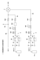
- FIG. 1 is an overall schematic diagram of a gas analyzer according to an embodiment of the present invention
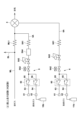
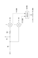
- FIG. 2 is a diagram of a fluid circuit connected to the FID detector of the embodiment.
- 2 is an overall schematic diagram of the gas analyzer according to the embodiment, showing a state during warm-up operation.
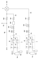
- FIG. 2 is an overall schematic diagram of the gas analyzer according to the embodiment, showing a state during a road test (main test).
- FIG. 4 is a flowchart showing a test procedure according to the embodiment.
- FIG. 13 is a diagram of a fluid circuit connected to an FID detector in an alternative embodiment.
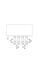
- FIG. 13 is a schematic diagram showing the configuration of a fuel gas port and a combustion supporting gas port in a modified embodiment.
- FIG. 13 is an overall schematic diagram of a gas analyzer according to a modified embodiment.
- the gas analyzer 100 of this embodiment is mounted on a vehicle VH such as an automobile, and measures the component concentrations of exhaust gas emitted from the vehicle VH.
- the on-board exhaust gas analyzer 100 can be used for a real driving emission (RDE) test.
- This vehicle-mounted exhaust gas analyzer 100 measures the component concentrations of exhaust gas sampled by an exhaust gas sampling mechanism 200, such as a sampling tube SP, which samples all or part of the exhaust gas emitted from an exhaust pipe EH connected to the engine E of a vehicle VH.
- the exhaust gas sampled by the exhaust gas sampling mechanism 200 is heated or maintained at a predetermined temperature by a heating tube HP and introduced into the vehicle-mounted exhaust gas analyzer 100.
- the gas analyzer 100 analyzes components to be measured, such as carbon monoxide (CO), carbon dioxide ( CO2 ), nitrogen oxides ( NOx ), methane ( CH4 ), or total hydrocarbons (THC), in exhaust gas, which is a sample gas.
- the gas analyzer 100 of this embodiment includes an NDIR detector 2 using a non-dispersive infrared absorption (NDIR) method, a CLD detector 3 using a chemiluminescence (CLD) method, and an FID detector 4 using a flame ionization (FID) method.
- NDIR non-dispersive infrared absorption
- CLD chemiluminescence
- FID detector 4 using a flame ionization
- the present embodiment includes the NDIR detector 2, the CLD detector 3, and the FID detector 4, the exhaust gas detector may include only the FID detector 4.
- the NDIR detector 2 continuously measures the concentration of carbon monoxide (CO) or carbon dioxide (CO 2 ) contained in the exhaust gas.
- the CLD detector 3 continuously measures the concentration of NOX or nitric oxide (NO) contained in the exhaust gas.
- the FID detector 4 continuously measures the concentration of methane (CH 4 ) or total hydrocarbons (THC) contained in the exhaust gas.
- the on-board exhaust gas analyzer 100 can be equipped with various analyzers depending on the components to be measured.
- a PMD meter using a magnetic pressure (PMD) method for example, a PMD meter using a magnetic pressure (PMD) method, an FTIR meter using a Fourier transform infrared spectroscopy (FTIR) method, a QCL-IR meter using a mid-infrared laser spectroscopy (QCL-IR) method, etc.
- PMD magnetic pressure
- FTIR Fourier transform infrared spectroscopy
- QCL-IR mid-infrared laser spectroscopy
- the analytical data obtained by these analyzers 2 to 4 is output to the information processing unit COM, which processes, records, or displays the analytical data.
- the information processing unit COM which processes, records, or displays the analytical data.
- each of the above multiple analyzers may be provided separately.
- the gas analyzer 100 of this embodiment is equipped with an FID detector 4 provided in the exhaust gas flow path ML through which the exhaust gas flows, a fuel gas supply mechanism 5 that supplies the FID detector 4 with fuel gas that serves as fuel for the hydrogen flame, and a combustion supporting gas supply mechanism 6 that supplies the FID detector 4 with a combustion supporting gas to help the combustion of the fuel gas.
- the fuel gas is a mixed gas in which helium or nitrogen is mixed with hydrogen to give a hydrogen concentration of 40% ⁇ 2% or 40% ⁇ 1%
- the combustion supporting gas is air (oxygen gas).
- Fuel gas supply mechanism 5 is configured to be able to supply fuel gas from two fuel gas cylinders 10 a and 10 b to the FID detector 4 .
- the fuel gas supply mechanism 5 has a first fuel gas port 51 to which the first fuel gas cylinder 10a is connected, a second fuel gas port 52 to which the second fuel gas cylinder is connected, a first fuel gas flow path 53 that connects the first fuel gas port 51 and the FID detector 4, and a second fuel gas flow path 54 that connects the second fuel gas port 52 and the FID detector 4.
- the first fuel gas port 51 is connected to the first fuel gas cylinder 10a during test preparation, such as warming up the engine, and when the first fuel gas cylinder 10a is removed, the port opening is closed by a closing structure (not shown), so that gas in the first fuel gas flow path 53 does not leak out to the outside.
- the second fuel gas port 52 is connected to the second fuel gas cylinder 10b during the actual test, which is, for example, a road driving test.
- the port opening is closed by a closing structure (not shown), so that the gas in the second fuel gas flow path 54 does not leak out to the outside.
- the first fuel gas flow passage 53 is a flow passage that supplies the fuel gas supplied from the first fuel gas port 51 to the FID detector 4, and in this embodiment, is connected to the upstream side of the FID detector 4 in the exhaust gas flow passage ML through which the exhaust gas flows.
- This first fuel gas flow passage 53 is provided with a first fuel gas check valve 55, which is a fuel gas backflow prevention mechanism 50 that prevents backflow from the second fuel gas flow passage 54 to the first fuel gas flow passage 53.
- This first fuel gas check valve 55 prevents fuel gas from flowing back into the first fuel gas port 51.
- the exhaust gas flow path ML is provided with a flow control device ML1 such as a capillary or orifice, and a bypass flow path BL for discharging a portion of the exhaust gas may be connected upstream of the flow control device ML1. A portion of the exhaust gas collected by the exhaust gas collection mechanism 200 is introduced into this exhaust gas flow path ML.
- a flow control device ML1 such as a capillary or orifice
- a bypass flow path BL for discharging a portion of the exhaust gas may be connected upstream of the flow control device ML1.
- a portion of the exhaust gas collected by the exhaust gas collection mechanism 200 is introduced into this exhaust gas flow path ML.
- the second fuel gas flow passage 54 is a flow passage that supplies the fuel gas supplied from the second fuel gas port 52 to the FID detector 4, and in this embodiment, is connected to the upstream side of the FID detector 4 in the exhaust gas flow passage ML through which the exhaust gas flows.
- This second fuel gas flow passage 54 is provided with a second fuel gas check valve 56, which is a fuel gas backflow prevention mechanism 50 that prevents backflow from the first fuel gas flow passage 53 to the second fuel gas flow passage 54.
- This second fuel gas check valve 56 prevents fuel gas from flowing back into the second fuel gas port 52.
- the first fuel gas flow path 53 and the second fuel gas flow path 54 merge downstream of the first fuel gas check valve 55 and the second fuel gas check valve 56, and the merged flow path 5A is connected to the exhaust gas flow path ML.
- a mixture of exhaust gas and fuel gas is supplied to the FID detector 4.
- This merged flow path 5A is provided with a flow control device 5A1, such as a capillary or orifice.
- the merged flow path 5A may be provided with an on-off valve 5A2, a pressure adjustment valve 5A3, a filter 5A4, or the like, as necessary. Note that when the first fuel gas flow path 53 and the second fuel gas flow path 54 do not merge with each other, the above-mentioned elements 5A1 to 5A4 can be provided in each of the flow paths 53 and 54.
- the combustion supporting gas supply mechanism 6 is configured to be able to supply the combustion supporting gas from two combustion supporting gas cylinders 11 a and 11 b to the FID detector 4 .
- the auxiliary gas supply mechanism 6 has a first auxiliary gas port 61 to which the first auxiliary gas cylinder 11a is connected, a second auxiliary gas port 62 to which the second auxiliary gas cylinder 11b is connected, a first auxiliary gas flow path 63 that connects the first auxiliary gas port 61 and the FID detector 4, and a second auxiliary gas flow path 64 that connects the second auxiliary gas port 62 and the FID detector 4.
- the first auxiliary gas port 61 is connected to the first auxiliary gas cylinder 11a, for example, during test preparation such as warm-up operation.
- the port opening is closed by a closing structure (not shown), so that the auxiliary gas in the first auxiliary gas flow passage 63 does not leak out to the outside.
- the second auxiliary gas port 62 is connected to the second auxiliary gas cylinder 11b during the actual test, which is, for example, a road driving test.
- the opening of the port is closed by a closing structure (not shown), so that the auxiliary gas in the second auxiliary gas flow passage 64 does not leak out to the outside.
- the first supporting gas flow path 63 is a flow path that supplies the supporting gas supplied from the first supporting gas port 61 to the FID detector 4, and in this embodiment is connected to the FID detector 4.
- the first supporting gas flow path 63 is provided with a first supporting gas check valve 65, which is a supporting gas backflow prevention mechanism 60 that prevents backflow from the second supporting gas flow path 64 to the first supporting gas flow path 63.
- the first supporting gas check valve 65 prevents supporting gas from flowing back to the first supporting gas port 61.
- the second supporting gas flow path 64 is a flow path that supplies the supporting gas supplied from the second supporting gas port 62 to the FID detector 4, and in this embodiment is connected to the FID detector 4.
- the second supporting gas flow path 64 is provided with a second supporting gas check valve 66, which is a supporting gas backflow prevention mechanism 60 that prevents backflow from the first supporting gas flow path 63 to the second supporting gas flow path 64.
- the second supporting gas check valve 66 prevents supporting gas from flowing back to the second supporting gas port 62.
- the first and second auxiliary gas flow paths 63 and 64 merge downstream of the first and second auxiliary gas check valves 65 and 66, and the merged flow path 6A is connected to the FID detector 4.
- a flow control device 6A1 such as a capillary or orifice, is provided in this merged flow path 6A.
- an on-off valve 6A2 or a pressure adjustment valve 6A3 may be provided in the merged flow path 6A as necessary. Note that when the first and second auxiliary gas flow paths 63 and 64 do not merge with each other, the above-mentioned elements 6A1 to 6A3 can be provided in the respective flow paths 63 and 64.
- Step S1 Preparation for Testing, such as Warming Up
- the first fuel gas cylinder 10a is connected to the first fuel gas port 51, and the first auxiliary gas cylinder 11a is connected to the first auxiliary gas port 61 (step S1).
- fuel gas is supplied from the first fuel gas cylinder 10a to the FID detector 4
- auxiliary gas is supplied from the second auxiliary gas cylinder 11a to the FID detector 4, and a hydrogen flame is ignited in the FID detector 4 (step S2).
- the preparation for testing is a process before the road test, and the first fuel gas cylinder 10a and the first auxiliary gas cylinder 11a do not necessarily need to be mounted on the vehicle. Therefore, the first fuel gas cylinder 10a and the first auxiliary gas cylinder 11a can be large capacity (large).
- step S3 When the test preparation is completed (step S3), as shown in Fig. 4 and Fig. 5, the second fuel gas cylinder 10b is connected to the second fuel gas port 52, and the second supporting gas cylinder 11b is connected to the second supporting gas port 62 (step S4). After connecting them, the first fuel gas cylinder 10a is removed from the first fuel gas port 51, and the first supporting gas cylinder 11a is removed from the first supporting gas port 61 (step S5). That is, the fuel gas supply to the FID detector 4 is continued even during replacement (switching) from the first fuel gas cylinder 10a to the second fuel gas cylinder 10b.
- the supporting gas supply to the FID detector 4 is continued even during replacement (switching) from the first supporting gas cylinder 11a to the second supporting gas cylinder 11b.
- the second fuel gas cylinder 10b and the second combustion supporting gas cylinder 11b are mounted on the vehicle, and small-capacity (compact) cylinders (e.g., with a capacity of 1 L or less) can be used.
- step S6 fuel gas is supplied from the second fuel gas cylinder 10b to the FID detector 4, and the supporting gas is supplied from the second supporting gas cylinder 11b to the FID detector 4, and a road test is performed (step S6).
- the fuel gas supply mechanism 5 can supply fuel gas from the two fuel gas cylinders 10a, 10b to the FID detector 4. As a result, it is possible to switch from one fuel gas cylinder 10a to the other fuel gas cylinder 10b without stopping the supply of fuel gas to the FID detector 4, that is, without causing the hydrogen flame in the FID detector 4 to extinguish.
- the supporting gas can be supplied from two supporting gas cylinders 11a and 11b to the FID detector 4.
- the supporting gas can be supplied from two supporting gas cylinders 11a and 11b to the FID detector 4.
- the first fuel gas check valve 55 is provided in the first fuel gas flow path 53
- the second fuel gas check valve 56 is provided in the second fuel gas flow path 54. Therefore, when replacing the fuel gas cylinders 10a, 10b, the fuel gas can be prevented from flowing back through the first fuel gas flow path 53 or the second fuel gas flow path 54 due to the pressure difference between the first fuel gas cylinder 10a and the second fuel gas cylinder 10b. As a result, problems caused by backflow (such as fuel gas leakage) can be eliminated.
- the first supporting gas flow path 63 is provided with the first supporting gas check valve 65
- the second supporting gas flow path 64 is provided with the second supporting gas check valve 66.
- the supporting gas when replacing the supporting gas cylinders 11a, 11b, the supporting gas can be prevented from flowing back through the first supporting gas flow path 63 or the second supporting gas flow path 64 due to the pressure difference between the first supporting gas cylinder 11a and the second supporting gas cylinder 11b.
- problems caused by backflow (such as leakage of combustion support gas) can be eliminated.
- the supporting gas supply mechanism 6 is configured to be able to supply supporting gas from two supporting gas cylinders 11a, 11b to the FID detector 4, but the supporting gas supply mechanism 6 may also be configured to supply supporting gas from a single supporting gas cylinder to the FID detector 4 (i.e., a configuration with a single supporting gas port).
- the fuel gas supply mechanism 5 may be configured to supply fuel gas from one fuel gas cylinder to the FID detector 4 (i.e., a configuration with one fuel gas port).
- the fuel gas backflow prevention mechanism 50 may be provided with an on-off valve, such as a solenoid valve, in each of the first fuel gas flow path 53 and the second fuel gas flow path 54.
- an on-off valve such as a solenoid valve
- the combustion supporting gas backflow prevention mechanism 60 may be provided with an on-off valve, such as an electromagnetic valve, in each of the first combustion supporting gas flow path 63 and the second combustion supporting gas flow path 64.
- an on-off valve such as an electromagnetic valve
- the gas analyzer 100 of the above embodiment has a built-in fuel gas supply mechanism 5 or a combustion supporting gas supply mechanism 6, but as shown in FIG. 6, the fuel gas supply mechanism 5 may be attached externally to one connection port P1 of the gas analyzer 100. Also, the combustion supporting gas supply mechanism 6 may be attached externally to one connection port P2 of the gas analyzer 100.
- the gas analyzer 100 may be configured such that a first fuel gas attachment A1 having a first fuel gas port 51 to which the first fuel gas cylinder 10a is connected and a first fuel gas check valve 55 is externally connected to the side wall 101 of the gas analyzer 100.
- the gas analyzer 100 may be configured such that a second fuel gas attachment A2 having a second fuel gas port 52 to which the second fuel gas cylinder 10b is connected and a second fuel gas check valve 56 is externally connected to the side wall 101 of the gas analyzer 100.
- the gas analyzer 100 may be configured such that a first auxiliary gas attachment B1 having a first auxiliary gas port 61 to which the first auxiliary gas cylinder 11a is connected and a first auxiliary gas check valve 65 is externally connected to the side wall 101 of the gas analyzer 100.
- the gas analyzer 100 may be configured such that a second auxiliary gas attachment B2 having a second auxiliary gas port 62 to which the second auxiliary gas cylinder 11b is connected and a second auxiliary gas check valve 66 is externally connected to the side wall 101 of the gas analyzer 100.
- the main test was a road test, but it may be a validation test.
- This validation test is performed by comparing the measurement accuracy of the on-board exhaust gas analyzer of the above embodiment with the measurement accuracy of a gas analyzer installed in a test room in a bench test using a dynamo such as a chassis dynamo.
- the gas analyzer 100 may include a methane concentration meter 7 that measures the concentration of methane contained in the sample gas in addition to the FID detector 4.
- a methane concentration meter 7 for example, a QCL-IR meter using a mid-infrared laser spectroscopy (QCL-IR) method, an IRLAM meter using an infrared laser absorption modulation (IRLAM) method, a combination of a non-methane cutter that cuts out hydrocarbon components other than methane and an FID meter, or an FTIR meter, etc. can be used.
- the gas analyzer 100 may further include a concentration calculation unit 8 that calculates the concentration of non-methane hydrocarbons by subtracting the methane concentration obtained by the methane concentration meter 7 from the total hydrocarbon concentration obtained by the FID detector 4.
- the concentration calculation unit 8 may be configured by the information processing unit COM of the above embodiment.
Landscapes
- Chemical & Material Sciences (AREA)
- General Physics & Mathematics (AREA)
- Engineering & Computer Science (AREA)
- Physics & Mathematics (AREA)
- Combustion & Propulsion (AREA)
- General Health & Medical Sciences (AREA)
- Analytical Chemistry (AREA)
- Biochemistry (AREA)
- Electrochemistry (AREA)
- Chemical Kinetics & Catalysis (AREA)
- Immunology (AREA)
- Pathology (AREA)
- Life Sciences & Earth Sciences (AREA)
- Health & Medical Sciences (AREA)
- Other Investigation Or Analysis Of Materials By Electrical Means (AREA)
Abstract
Description
特に本発明では、第1燃料ガス流路から第2燃料ガス流路への逆流、又は、第2燃料ガス流路から第1燃料ガス流路への逆流を防止する燃料ガス逆流防止機構を設けているので、燃料ガスボンベを交換する際に、第1燃料ガスボンベと第2燃料ガスボンベとの圧力差によって、第1燃料ガス流路又は第2燃料ガス流路を燃料ガスが逆流することを防止できる。その結果、逆流により生じる不具合(例えば燃料ガスの漏洩等)を解消することができる。
この構成であれば、各燃料ガス流路に逆止弁を設けるという簡単な構成により、第1燃料ガス流路から第2燃料ガス流路への逆流、及び、第2燃料ガス流路から第1燃料ガス流路への逆流を防止することができる。
この構成であれば、2つの助燃ガスボンベから助燃ガスを水素炎イオン化検出器に供給することができる。その結果、水素炎イオン化検出器への助燃ガスの供給を止めることなく、つまり、水素炎イオン化検出器における水素炎を失火させることなく、一方の助燃ガスボンベから他方の助燃ガスボンベに交換することができる。
特に本発明では、第1助燃ガス流路から第2助燃ガス流路への逆流、又は、第2助燃ガス流路から第1助燃ガス流路への逆流を防止する助燃ガス逆流防止機構を設けているので、助燃ガスボンベを交換する際に、第1助燃ガスボンベと第2助燃ガスボンベとの圧力差によって、第1助燃ガス流路又は第2助燃ガス流路を助燃ガスが逆流することを防止できる。その結果、逆流により生じる不具合(例えば助燃ガスの漏洩等)を解消することができる。
この構成であれば、各助燃ガス流路に逆止弁を設けるという簡単な構成により、第1助燃ガス流路から第2助燃ガス流路への逆流、及び、第2助燃ガス流路から第1助燃ガス流路への逆流を防止することができる。
この構成であれば、路上走行試験前の暖機運転等の試験準備と、路上走行試験である本試験とで燃料ガスボンベ又は助燃ガスボンベを交換して、試験を行うことができる。
この構成であれば、路上走行試験前の暖機運転等の試験準備と、路上走行試験である本試験とで燃料ガスボンベ又は助燃ガスボンベを交換して、試験を行うことができる。
この構成であれば、小型の燃料ガスボンベを用いることができ、車両への積載量を減らすことができる。
以下に、本発明に係るガス分析装置の一実施形態について、図面を参照して説明する。
なお、以下に示すいずれの図についても、わかりやすくするために、適宜省略し又は誇張して模式的に描かれている。同一の構成要素については、同一の符号を付して説明を適宜省略する。
本実施形態のガス分析装置100は、例えば自動車等の車両VHに搭載されて、当該車両VHから排出される排ガスの成分濃度を測定するものである。なお、車載型排ガス分析装置100は、実路走行試験(Real Driving Emission;RDE)に用いることができる。
燃料ガス供給機構5は、2つの燃料ガスボンベ10a、10bから燃料ガスをFID検出器4に供給可能に構成されている。
助燃ガス供給機構6は、2つの助燃ガスボンベ11a、11bから助燃ガスをFID検出器4に供給可能に構成されている。
本実施形態のガス分析装置100を用いたガス分析方法について、図3~図5を参照して説明する。
ガス分析装置100の暖機運転等の試験準備において、図3及び図5に示すように、第1燃料ガスポート51に第1燃料ガスボンベ10aを接続し、第1助燃ガスポート61に第1助燃ガスボンベ11aを接続する(ステップS1)。これにより、第1燃料ガスボンベ10aからFID検出器4に燃料ガスを供給するとともに、第2助燃ガスボンベ11aからFID検出器4に助燃ガスを供給して、FID検出器4において水素炎を着火する(ステップS2)。ここで、ガス分析装置100の暖機運転等の試験準備は、路上走行試験前の工程であり、第1燃料ガスボンベ10a及び第1助燃ガスボンベ11aは、必ずしも車載する必要ない。そのため、第1燃料ガスボンベ10a及び第1助燃ガスボンベ11aは、大容量(大型)のものを用いることができる。
試験準備が終了すると(ステップS3)、図4及び図5に示すように、第2燃料ガスポート52に第2燃料ガスボンベ10bを接続し、第2助燃ガスポート62に第2助燃ガスボンベ11bを接続する(ステップS4)。それらを接続した後に、第1燃料ガスポート51から第1燃料ガスボンベ10aを取り外し、第1助燃ガスポート61から第1助燃ガスボンベ11aを取り外す(ステップS5)。つまり、第1燃料ガスボンベ10aから第2燃料ガスボンベ10bに交換する(切り替える)間も、FID検出器4への燃料ガス供給が継続される。また、第1助燃ガスボンベ11aから第2助燃ガスボンベ11bに交換する(切り替える)間も、FID検出器4への助燃ガス供給が継続される。ここで、第2燃料ガスボンベ10b及び第2助燃ガスボンベ11bは、車載されるものであり、また、小容量(小型)のもの(例えば内容量が1L以下)を用いることができる。
このように構成した本実施形態のガス分析装置100によれば、燃料ガス供給機構5が、2つの燃料ガスボンベ10a、10bから燃料ガスをFID検出器4に供給することができる。その結果、FID検出器4への燃料ガスの供給を止めることなく、つまり、FID検出器4における水素炎を失火させることなく、一方の燃料ガスボンベ10aから他方の燃料ガスボンベ10bに交換することができる。
例えば、助燃ガス供給機構6が2つの助燃ガスボンベ11a、11bからFID検出器4に助燃ガスを供給可能に構成しているが、助燃ガス供給機構6は、1つの助燃ガスボンベからFID検出器4に助燃ガスを供給する構成(つまり、助燃ガスポートが1つの構成)としても良い。
4 ・・・水素炎イオン化検出器
5 ・・・燃料ガス供給機構
10a・・・第1燃料ガスボンベ
10b・・・第2燃料ガスボンベ
51 ・・・第1燃料ガスポート
52 ・・・第2燃料ガスポート
53 ・・・第1燃料ガス流路
54 ・・・第2燃料ガス流路
50 ・・・燃料ガス逆流防止機構
55 ・・・第1燃料ガス逆止弁
56 ・・・第2燃料ガス逆止弁
6 ・・・助燃ガス供給機構
11a・・・第1助燃ガスボンベ
11b・・・第2助燃ガスボンベ
61 ・・・第1助燃ガスポート
62 ・・・第2助燃ガスポート
63 ・・・第1助燃ガス流路
64 ・・・第2助燃ガス流路
60 ・・・助燃ガス逆流防止機構
65 ・・・第1助燃ガス逆止弁
66 ・・・第2助燃ガス逆止弁
7 ・・・メタン濃度計
8 ・・・濃度算出部
Claims (13)
- サンプルガスに含まれる炭化水素成分を分析するガス分析装置であって、
前記炭化水素成分を測定する水素炎イオン化検出器と、
前記水素炎イオン化検出器に燃料ガスを供給する燃料ガス供給機構とを備え、
前記燃料ガス供給機構は、
第1燃料ガスボンベが接続される第1燃料ガスポートと、
第2燃料ガスボンベが接続される第2燃料ガスポートと、
前記第1燃料ガスポート及び前記水素炎イオン化検出器を接続する第1燃料ガス流路と、
前記第2燃料ガスポート及び前記水素炎イオン化検出器を接続する第2燃料ガス流路と、
前記第1燃料ガス流路から前記第2燃料ガス流路への逆流、又は、前記第2燃料ガス流路から前記第1燃料ガス流路への逆流を防止する燃料ガス逆流防止機構とを備える、ガス分析装置。 - 前記燃料ガス逆流防止機構は、
前記第1燃料ガス流路に設けられ、前記第2燃料ガス流路から前記第1燃料ガス流路への逆流を防止する第1燃料ガス逆止弁と、
前記第2燃料ガス流路に設けられ、前記第1燃料ガス流路から前記第2燃料ガス流路への逆流を防止する第2燃料ガス逆止弁とを備える、請求項1に記載のガス分析装置。 - 前記ガス分析装置の試験準備中は、前記第1燃料ガスポートに前記第1燃料ガスボンベが接続され、前記試験準備の終了後に、前記第2燃料ガスポートに前記第2燃料ガスボンベが接続されるとともに、前記第1燃料ガスポートから前記第1燃料ガスボンベが取り外され、その後、前記ガス分析装置を用いた前記サンプルガスの本試験が開始される、請求項1又は2に記載のガス分析装置。
- 前記ガス分析装置の試験準備中は、前記第1燃料ガスボンベを備え、
前記ガス分析装置を用いた前記サンプルガスの本試験中は、前記第2燃料ガスボンベを備える、請求項1乃至3の何れか一項に記載のガス分析装置。 - 前記水素炎イオン化検出器に助燃ガスを供給する助燃ガス供給機構とを備え、
前記助燃ガス供給機構は、
第1助燃ガスボンベが接続される第1助燃ガスポートと、
第2助燃ガスボンベが接続される第2助燃ガスポートと、
前記第1助燃ガスポート及び前記水素炎イオン化検出器を接続する第1助燃ガス流路と、
前記第2助燃ガスポート及び前記水素炎イオン化検出器を接続する第2助燃ガス流路と、
前記第1助燃ガス流路から前記第2助燃ガス流路への逆流、又は、前記第2助燃ガス流路から前記第1助燃ガス流路への逆流を防止する助燃ガス逆流防止機構とを備える、請求項1乃至4の何れか一項に記載のガス分析装置。 - 前記助燃ガス逆流防止機構は、
前記第1助燃ガス流路に設けられ、前記第2助燃ガス流路から前記第1助燃ガス流路への逆流を防止する第1助燃ガス逆止弁と、
前記第2助燃ガス流路に設けられ、前記第1助燃ガス流路から前記第2助燃ガス流路への逆流を防止する第2助燃ガス逆止弁とを備える、請求項5に記載のガス分析装置。 - 車両に搭載されて、当該車両からの排ガスに含まれる炭化水素成分を分析する車両搭載型のものである、請求項1乃至6の何れか一項に記載のガス分析装置。
- 前記サンプルガスに含まれるメタンの濃度を測定するメタン濃度計と、
前記水素炎イオン化検出器により得られた全炭化水素濃度から前記メタン濃度を差し引いてノンメタンハイドロカーボンの濃度を算出する濃度算出部とをさらに備える、請求項1乃至7の何れか一項に記載のガス分析装置。 - サンプルガスに含まれる炭化水素成分を測定する水素炎イオン化検出器に燃料ガスを供給する燃料ガス供給機構であって、
第1燃料ガスボンベが接続される第1燃料ガスポートと、
第2燃料ガスボンベが接続される第2燃料ガスポートと、
前記第1燃料ガスポート及び前記水素炎イオン化検出器を接続する第1燃料ガス流路と、
前記第2燃料ガスポート及び前記水素炎イオン化検出器を接続する第2燃料ガス流路と、
前記第1燃料ガス流路から前記第2燃料ガス流路への逆流、又は、前記第2燃料ガス流路から前記第1燃料ガス流路への逆流を防止する燃料ガス逆流防止機構とを備える、燃料ガス供給機構。 - 請求項1乃至8の何れか一項に記載のガス分析装置を用いたガス分析方法であって、
前記ガス分析装置の試験準備中は、前記第1燃料ガスポートに接続された前記第1燃料ガスボンベから前記水素炎イオン化検出器に前記燃料ガスを供給し、
前記ガス分析装置を用いた前記サンプルガスの本試験中は、前記第2燃料ガスポートに接続された前記第2燃料ガスボンベから前記水素炎イオン化検出器に前記燃料ガスを供給する、ガス分析方法。 - 請求項5に記載のガス分析装置を用いたガス分析方法であって、
前記ガス分析装置の試験準備中は、前記第1燃料ポートに接続された前記第1燃料ガスボンベから前記水素炎イオン化検出器に前記燃料ガスを供給し、第1助燃ガスポートに接続された前記助燃ガスボンベから前記水素炎イオン化検出器に前記助燃ガスを供給し、
前記ガス分析装置を用いた前記サンプルガスの本試験中は、前記第2燃料ガスポートに接続された前記第2燃料ガスボンベから前記水素炎イオン化検出器に前記燃料ガスを供給し、前記第2助燃ガスポートに接続された前記第2助燃ガスボンベから前記水素炎イオン化検出器に前記助燃ガスを供給する、ガス分析方法。 - 前記本試験は、路上走行試験である、請求項10又は11に記載のガス分析方法。
- 前記第2燃料ガスポートに接続される前記燃料ガスボンベの内容量は1L以下である、請求項10乃至12の何れか一項に記載のガス分析方法。
Priority Applications (3)
| Application Number | Priority Date | Filing Date | Title |
|---|---|---|---|
| CN202480040757.5A CN121359022A (zh) | 2023-06-30 | 2024-05-20 | 气体分析装置、燃料气体供给机构及气体分析方法 |
| JP2025529512A JPWO2025004598A1 (ja) | 2023-06-30 | 2024-05-20 | |
| DE112024002787.3T DE112024002787T5 (de) | 2023-06-30 | 2024-05-20 | Gasanalysator, Brenngas-Zufuhrmechanismus und Gasanalyseverfahren |
Applications Claiming Priority (2)
| Application Number | Priority Date | Filing Date | Title |
|---|---|---|---|
| JP2023-108056 | 2023-06-30 | ||
| JP2023108056 | 2023-06-30 |
Publications (1)
| Publication Number | Publication Date |
|---|---|
| WO2025004598A1 true WO2025004598A1 (ja) | 2025-01-02 |
Family
ID=93938460
Family Applications (1)
| Application Number | Title | Priority Date | Filing Date |
|---|---|---|---|
| PCT/JP2024/018439 Ceased WO2025004598A1 (ja) | 2023-06-30 | 2024-05-20 | ガス分析装置、燃料ガス供給機構、及び、ガス分析方法 |
Country Status (4)
| Country | Link |
|---|---|
| JP (1) | JPWO2025004598A1 (ja) |
| CN (1) | CN121359022A (ja) |
| DE (1) | DE112024002787T5 (ja) |
| WO (1) | WO2025004598A1 (ja) |
Citations (4)
| Publication number | Priority date | Publication date | Assignee | Title |
|---|---|---|---|---|
| JPH1077828A (ja) * | 1996-09-04 | 1998-03-24 | Denso Corp | 排気微粒子浄化装置 |
| JP2001281138A (ja) * | 2000-03-30 | 2001-10-10 | Shimadzu Corp | フレーム式原子吸光分光光度計 |
| JP2003057221A (ja) * | 2001-08-13 | 2003-02-26 | Showa Kankyo Engineering Kk | 焼却炉排ガス中の有害大気汚染物質の連続分析方法及び装置 |
| JP2020095013A (ja) * | 2018-12-12 | 2020-06-18 | 株式会社堀場製作所 | 排ガス分析装置、排ガス分析方法、及び補正式作成方法 |
-
2024
- 2024-05-20 CN CN202480040757.5A patent/CN121359022A/zh active Pending
- 2024-05-20 DE DE112024002787.3T patent/DE112024002787T5/de active Pending
- 2024-05-20 JP JP2025529512A patent/JPWO2025004598A1/ja active Pending
- 2024-05-20 WO PCT/JP2024/018439 patent/WO2025004598A1/ja not_active Ceased
Patent Citations (4)
| Publication number | Priority date | Publication date | Assignee | Title |
|---|---|---|---|---|
| JPH1077828A (ja) * | 1996-09-04 | 1998-03-24 | Denso Corp | 排気微粒子浄化装置 |
| JP2001281138A (ja) * | 2000-03-30 | 2001-10-10 | Shimadzu Corp | フレーム式原子吸光分光光度計 |
| JP2003057221A (ja) * | 2001-08-13 | 2003-02-26 | Showa Kankyo Engineering Kk | 焼却炉排ガス中の有害大気汚染物質の連続分析方法及び装置 |
| JP2020095013A (ja) * | 2018-12-12 | 2020-06-18 | 株式会社堀場製作所 | 排ガス分析装置、排ガス分析方法、及び補正式作成方法 |
Also Published As
| Publication number | Publication date |
|---|---|
| JPWO2025004598A1 (ja) | 2025-01-02 |
| CN121359022A (zh) | 2026-01-16 |
| DE112024002787T5 (de) | 2026-04-16 |
Similar Documents
| Publication | Publication Date | Title |
|---|---|---|
| US6412333B2 (en) | Exhaust gas analyzing system | |
| EP0681182B1 (en) | Instrument for measuring non-methane organic gases in gas samples | |
| US8516908B2 (en) | Sample system for gaseous emission measurement | |
| US5753185A (en) | Vehicle emissions testing system | |
| CN209471083U (zh) | 一种非甲烷总烃含量检测装置 | |
| US7281440B2 (en) | Particulate sampling system having flow check device | |
| JP2020095013A (ja) | 排ガス分析装置、排ガス分析方法、及び補正式作成方法 | |
| CN100526872C (zh) | 汽车用氧传感器性能测试装置 | |
| JP4925489B1 (ja) | ガス分析装置 | |
| CN114235941A (zh) | 一种环境空气中非甲烷总烃的直接检测装置及方法 | |
| WO2025004598A1 (ja) | ガス分析装置、燃料ガス供給機構、及び、ガス分析方法 | |
| JP6810649B2 (ja) | ガス分析装置 | |
| JP4896267B1 (ja) | ガス分析装置 | |
| Adachi | Emission measurement techniques for advanced powertrains | |
| JP3511539B2 (ja) | キャニスターの炭化水素吸脱着性能評価装置 | |
| JP2010139281A (ja) | 排気ガス測定装置 | |
| US20060222563A1 (en) | Gas analyzer and method for controlling hydrogen flame ionization detector | |
| US5431043A (en) | Catalyst activity test | |
| JP7528237B2 (ja) | ガス分析装置及びガス分析方法 | |
| Sur et al. | Laser-based in-exhaust gas sensor for on-road vehicles | |
| JP3502532B2 (ja) | 定容量試料採取装置およびこれを用いたガス分析方法 | |
| Nevius et al. | Speciation of nitrogen oxides in a light duty diesel engine during an EGR system failure | |
| JPWO2025004598A5 (ja) | ||
| Lenaers et al. | Mobile emission measurements for assessing low emitting vehicles exemplified on a CRT-equipped bus | |
| JP2006214949A (ja) | 排ガス測定装置 |
Legal Events
| Date | Code | Title | Description |
|---|---|---|---|
| 121 | Ep: the epo has been informed by wipo that ep was designated in this application |
Ref document number: 24831470 Country of ref document: EP Kind code of ref document: A1 |
|
| ENP | Entry into the national phase |
Ref document number: 2025529512 Country of ref document: JP Kind code of ref document: A |
|
| WWE | Wipo information: entry into national phase |
Ref document number: 2025529512 Country of ref document: JP |
|
| WWE | Wipo information: entry into national phase |
Ref document number: 202517126754 Country of ref document: IN |
|
| WWP | Wipo information: published in national office |
Ref document number: 202517126754 Country of ref document: IN |
|
| WWE | Wipo information: entry into national phase |
Ref document number: 112024002787 Country of ref document: DE |