WO2025004591A1 - 電池モジュール - Google Patents
電池モジュール Download PDFInfo
- Publication number
- WO2025004591A1 WO2025004591A1 PCT/JP2024/018287 JP2024018287W WO2025004591A1 WO 2025004591 A1 WO2025004591 A1 WO 2025004591A1 JP 2024018287 W JP2024018287 W JP 2024018287W WO 2025004591 A1 WO2025004591 A1 WO 2025004591A1
- Authority
- WO
- WIPO (PCT)
- Prior art keywords
- battery
- fuse
- battery module
- cell
- tab
- Prior art date
- Legal status (The legal status is an assumption and is not a legal conclusion. Google has not performed a legal analysis and makes no representation as to the accuracy of the status listed.)
- Ceased
Links
Images


Classifications
-
- Y—GENERAL TAGGING OF NEW TECHNOLOGICAL DEVELOPMENTS; GENERAL TAGGING OF CROSS-SECTIONAL TECHNOLOGIES SPANNING OVER SEVERAL SECTIONS OF THE IPC; TECHNICAL SUBJECTS COVERED BY FORMER USPC CROSS-REFERENCE ART COLLECTIONS [XRACs] AND DIGESTS
- Y02—TECHNOLOGIES OR APPLICATIONS FOR MITIGATION OR ADAPTATION AGAINST CLIMATE CHANGE
- Y02E—REDUCTION OF GREENHOUSE GAS [GHG] EMISSIONS, RELATED TO ENERGY GENERATION, TRANSMISSION OR DISTRIBUTION
- Y02E60/00—Enabling technologies; Technologies with a potential or indirect contribution to GHG emissions mitigation
- Y02E60/10—Energy storage using batteries
Definitions
- the present invention relates to a battery module.
- Battery modules are equipped with battery cells.
- Patent Documents 1 and 2 describe an FPC (flexible printed circuit board).
- the FPC has a conductive pattern.
- the conductive pattern includes a fuse portion.
- Fuses may be electrically connected to battery cells.
- fuses mounted on a rigid substrate such as a PCB (printed circuit board) are electrically connected to a battery cell, it can be difficult to improve the freedom of the fuse's shape.
- One object of the present invention is to improve the flexibility of the shape of the fuse that is electrically connected to the battery cell. Other objects of the present invention will become apparent from the description of this specification.
- a battery cell a flexible substrate having a fuse electrically connected to the battery cell;
- a battery module comprising: 2.
- the flexible substrate further includes a support to which the flexible substrate is attached. the support defines an overlap region at least partially overlapping the fuse and a surrounding region at least partially surrounding the overlap region; 1.
- the battery module according to claim 1 wherein the thermal conductivity of the overlapping region is less than the thermal conductivity of the surrounding region.
- 3. The battery module according to 2., wherein the overlapping region defines a hole penetrating the support.
- the above aspect of the present invention allows for greater freedom in the shape of the fuse that is electrically connected to the battery cell.
- FIG. 2 is a perspective view of a battery module according to the embodiment;
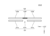
- FIG. 2 is a front view of a portion of a battery module according to an embodiment. This is a cross-sectional view taken along line AA in FIG.
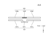
- FIG. 4 is a diagram showing a modification of FIG. 3 .
- FIG. 1 is a perspective view of a battery module 100 according to an embodiment.
- FIG. 2 is a front view of a portion of the battery module 100 according to an embodiment.
- FIG. 3 is a cross-sectional view taken along line A-A in FIG. 2.
- the multiple voltage detection terminals 122, multiple flexible boards 123, and multiple voltage detection lines 124 shown in FIG. 2 have been removed from FIG. 1.
- the X direction indicates the front-to-rear direction of the battery module 100.
- the Y direction is perpendicular to the X direction.
- the Y direction indicates the left-to-right direction of the battery module 100.
- the Z direction is perpendicular to both the X and Y directions.
- the Z direction indicates the up-down direction of the battery module 100.
- the arrows pointing to the X direction, the Y direction, and the Z direction indicate the rear, left, and up directions of the battery module 100, respectively.
- a white circle with an X indicating the Z direction or the X direction indicates that the arrow pointing in the direction indicated by the white circle extends from the front to the back of the paper.
- the tip side of the arrow indicating the X direction will be referred to as the +X side
- the opposite side of the tip of the arrow indicating the X direction will be referred to as the -X side
- the tip side of the arrow indicating the Y direction will be referred to as the +Y side
- the opposite side of the tip of the arrow indicating the Y direction will be referred to as the -Y side
- the tip side of the arrow indicating the Z direction will be referred to as the +Z side
- the opposite side of the tip of the arrow indicating the Z direction will be referred to as the -Z side.
- the relationship between the X direction, Y direction, and Z direction and the front-rear direction, left-right direction, and up-down direction of the battery module 100 is not limited to
- the battery module 100 will be described with reference to FIG. 1 and, if necessary, FIG. 2.
- the battery module 100 includes a plurality of battery cells 110 and a voltage detection device 120.
- the multiple battery cells 110 are stacked in the Y direction.
- the multiple battery cells 110 stacked in the Y direction will be referred to as a stack of battery cells 110.
- the dimension of each battery cell 110 in the X direction is the dimension in the longitudinal direction of each battery cell 110.
- the dimension of each battery cell 110 in the Z direction is the dimension in the lateral direction of each battery cell 110.
- the dimension of each battery cell 110 in the Y direction is the dimension in the thickness direction of each battery cell 110.
- the shape of each battery cell 110 is not limited to this example.
- Each battery cell 110 includes a battery element (not shown), an exterior material 112, a positive electrode tab 114, and a negative electrode tab 116.
- the battery element includes a plurality of positive electrodes and a plurality of negative electrodes (not shown) stacked alternately in the Y direction, and a separator (not shown) located between adjacent positive electrodes and negative electrodes in the Y direction.
- the exterior material 112 seals the battery element and an electrolyte (not shown).
- the positive electrode tab 114 is electrically connected to the positive electrode of the battery element.
- the positive electrode tab 114 is pulled out from one of both sides of the exterior material 112 in the X direction.
- the negative electrode tab 116 is electrically connected to the negative electrode of the battery element.
- the negative electrode tab 116 is pulled out from the other side of both sides of the exterior material 112 in the X direction.
- the structure of each battery cell 110 is not limited to this example.
- Each battery cell 110 may be an all-solid-state battery.
- an all-solid-state battery a solid electrolyte layer is provided in the portion corresponding to the separator.
- An all-solid-state battery does not contain an electrolyte.
- each battery cell 110 will be described as a battery cell containing an electrolyte.
- the battery cells 110 are electrically connected in a combination of series and parallel. Specifically, a cell group including at least two battery cells 110 adjacent to each other in the Y direction and connected in parallel is stacked in the Y direction and connected in series. On the -X side of the stack of battery cells 110, a positive electrode tab 114 drawn from a battery cell 110 of one cell group connected in parallel and a negative electrode tab 116 drawn from a battery cell 110 of another cell group connected in parallel are electrically connected to each other, and a tab group 118 including the positive electrode tab 114 and the negative electrode tab 116 is located. The positive electrode tab 114 and the negative electrode tab 116 in the tab group 118 are joined to each other by, for example, laser welding.
- the tab group 118 is also located on the +X side of the stack of battery cells 110.
- a plurality of cell groups are connected in series from the cell group located at one end side of the stack of battery cells 110 in the Y direction to the cell group located at the other end side of the stack of battery cells 110 in the Y direction.
- the tab group 118 located on the -X side of the stack of battery cells 110 will be referred to as the -X side tab group 118
- the tab group 118 located on the +X side of the stack of battery cells 110 will be referred to as the +X side tab group 118.
- the electrical connection of the multiple battery cells 110 is not limited to the above example.
- a stack of battery cells 110 may be formed by connecting single battery cells 110 in series.
- the voltage detection device 120 detects the voltages of the multiple -X side tab groups 118. As shown in Figures 1 and 2, the voltage detection device 120 has a protector 121, multiple voltage detection terminals 122, multiple flexible boards 123, multiple voltage detection lines 124, a positive bus bar 125, and a negative bus bar 126.
- the protector 121 covers the -X side portion of the stack of battery cells 110.
- the protector 121 is, for example, an insulator such as resin.
- the protector 121 has multiple frame bodies 121f.
- Each of the multiple -X side tab groups 118 is exposed toward the -X side from an opening defined by each of the multiple frame bodies 121f.
- Each of the multiple frame bodies 121f at least partially surrounds each of the multiple -X side tab groups 118. Therefore, each frame body 121f can protect each tab group 118 from members external to each frame body 121f.
- Each of the multiple voltage detection terminals 122 is located on the -X side of each of the multiple -X side tab groups 118.
- Each voltage detection terminal 122 is, for example, a conductor such as metal.
- the +X side surface of each voltage detection terminal 122 and the -X side surface of each -X side tab group 118 are joined to each other by a joining method such as laser welding. Therefore, each voltage detection terminal 122 and each -X side tab group 118 are electrically connected to each other. Therefore, the voltage detection device 120 can detect the voltage of each -X side tab group 118 by each voltage detection terminal 122.
- the multiple voltage detection terminals 122 are held together by the protector 121. Therefore, by placing the protector 121 at an appropriate position with respect to the stack of battery cells 110, each of the multiple voltage detection terminals 122 can be placed at an appropriate position with respect to each of the multiple -X side tab groups 118.
- the positive bus bar 125 is disposed at the -Y side end of the protector 121.
- the positive bus bar 125 is electrically connected to the positive tab 114 drawn out to the -X side from the battery cell 110 of the cell group located at the -Y side end of the stack of battery cells 110.
- the positive bus bar 125 functions as an external terminal for electrically connecting the battery module 100 to an external device such as another battery module.
- the negative bus bar 126 is disposed at the end portion on the +Y side of the protector 121.
- the negative bus bar 126 is electrically connected to the negative tab 116 drawn out to the -X side from the battery cell 110 of the cell group located at the end portion on the +Y side of the stack of battery cells 110.
- the negative bus bar 126 functions as an external terminal for electrically connecting the battery module 100 to an external device such as another battery module.
- the positive electrode tab 114 at the end of the multiple cell groups connected in series is pulled out toward the -X side from the battery cell 110 of the cell group located at the -Y side end of the stack of battery cells 110
- the negative electrode tab 116 at the end of the multiple cell groups connected in series is pulled out toward the -X side from the battery cell 110 of the cell group located at the +Y side end of the stack of battery cells 110.
- the positive electrode bus bar 125 is disposed on the -X side and -Y side of the stack of battery cells 110
- the negative electrode bus bar 126 is disposed on the -X side and +Y side of the stack of battery cells 110.
- the arrangement of the positive electrode tab 114 and the negative electrode tab 116 at the end of the multiple cell groups connected in series may differ depending on the number of battery cells 110 included in the stack of battery cells 110.
- the positive electrode tab 114 at the end of a group of cells connected in series may be drawn out toward the -X side from the battery cell 110 of the cell group located at the -Y end of the stack of battery cells 110
- the negative electrode tab 116 at the end of a group of cells connected in series may be drawn out toward the +X side from the battery cell 110 of the cell group located at the +Y end of the stack of battery cells 110.
- the positive electrode bus bar 125 is disposed on the -X side and -Y side of the stack of battery cells 110
- the negative electrode bus bar 126 is disposed on the +X side and +Y side of the stack of battery cells 110.
- the flexible substrate 123 will be described with reference to Figures 2 and 3.
- the flexible substrate 123 includes a base film 123b and a fuse 123f.
- the flexible substrate 123 is a flexible printed circuit (FPC).
- the flexible substrate 123 and the protector 121 are mechanically attached to each other by mechanical bonding such as engagement or clamping.
- the protector 121 serves as a support for supporting the flexible substrate 123.
- the support for supporting the flexible substrate 123 may be a member different from the protector 121.
- the base film 123b is arranged such that the longitudinal direction of the base film 123b is approximately parallel to the Z direction and the direction perpendicular to the base film 123b is approximately parallel to the X direction.
- the base film 123b has electrical insulation properties.
- the base film 123b is, for example, a resin film.
- the fuse 123f is a conductor pattern provided on the base film 123b.
- the conductor pattern provided on the flexible substrate 123 may constitute only the fuse 123f.
- the -Z side end portion of the fuse 123f and the -Y side end portion of the voltage detection terminal 122 are electrically connected to each other.
- the fuse 123f and the -X side tab group 118 are electrically connected to each other via the voltage detection terminal 122.
- the +Z side end portion of the fuse 123f and one end portion of the voltage detection line 124 are electrically connected to each other.
- the fuse 123f may be at least partially embedded in the base film 123b, or may be provided on at least one side of the +X side surface and the -X side surface of the base film 123b.
- fuse 123f melts.
- the current at which the fuse 123f melts can be determined by the cross-sectional area of the fuse 123f.
- fuse 123f is illustrated as being zigzag-shaped.
- the actual shape of fuse 123f is not limited to the shape shown in FIG. 2 as long as fuse 123f can function as a fuse.
- the base film 123b is flexible. Therefore, the flexible substrate 123 can be deformed more easily than a rigid substrate such as a PCB (printed circuit board). This improves the degree of freedom in the shape of the fuse 123f compared to when the fuse 123f is provided on a rigid substrate.
- the flexible substrate 123 can be bent at least partially toward the +X side or the -X side. This makes it easier for the fuse 123f to follow the displacement of the voltage detection terminal 122 compared to when the fuse 123f is provided on a rigid substrate.
- the protector 121 defines a hole 121h and an enclosed area 121s.
- the hole 121h at least partially overlaps with the fuse 123f in the X direction.
- the surrounding region 121s at least partially surrounds the hole 121h in the X direction.
- the protector 121 defines a gap by the hole 121h. Therefore, the thermal conductivity of the gap inside the hole 121h is less than the thermal conductivity of the surrounding region 121s. Therefore, compared to a case where a region having a thermal conductivity equal to or greater than that of the surrounding region 121s is provided inside the hole 121h, it is possible to make it difficult for heat generated from the fuse 123f to escape to the protector 121, and it is possible to make it easier to accurately melt the fuse 123f at the design temperature.
- FIG. 4 shows a modified example of FIG. 3.
- the protector 121 may define a recess 121r instead of the hole 121h shown in FIG. 3.
- the recess 121r is recessed toward the side away from the fuse 123f with respect to the surrounding region 121s. Therefore, the protector 121 defines a gap by the recess 121r. Therefore, the thermal conductivity of the gap inside the recess 121r is less than the thermal conductivity of the surrounding region 121s.
- the overlapping region that at least partially overlaps with fuse 123f of protector 121 in the X-direction may have a material with a thermal conductivity lower than that of surrounding region 121s, instead of a gap defined by a structure such as hole 121h or recess 121r.
- the overlapping region has such a material, it is possible to make it difficult for heat generated from fuse 123f to escape to protector 121, compared to when the thermal conductivity of the overlapping region is equal to or higher than that of surrounding region 121s, and it is possible to make it easier to accurately melt fuse 123f at the design temperature.
Landscapes
- Battery Mounting, Suspending (AREA)
- Connection Of Batteries Or Terminals (AREA)
Abstract
電池モジュール(100)は、電池セル(110)と、電池セル(110)に電気的に接続されたヒューズ(123f)を有するフレキシブル基板(123)と、を備えている。
Description
本発明は、電池モジュールに関する。
近年、様々な電池モジュールが開発されている。電池モジュールは、電池セルを備えている。
特許文献1及び2には、FPC(フレキシブルプリント配線板)について記載されている。FPCは、導電パターンを有している。導電パターンは、ヒューズ部を含んでいる。
電池セルには、ヒューズが電気的に接続されることがある。しかしながら、PCB(プリント回路基板)等のリジッド基板に設けられたヒューズを電池セルに電気的に接続させた場合、ヒューズの形状の自由度を向上させることが難しいことがある。
本発明の目的の一例は、電池セルに電気的に接続されるヒューズの形状の自由度を向上させることにある。本発明の他の目的は、本明細書の記載から明らかになるであろう。
本発明の一態様は、以下のとおりである。
1.電池セルと、
前記電池セルに電気的に接続されたヒューズを有するフレキシブル基板と、
を備える電池モジュール。
2.前記フレキシブル基板が取り付けられた支持体をさらに備え、
前記支持体は、前記ヒューズと少なくとも部分的に重なる重複領域と、前記重複領域を少なくとも部分的に囲む囲繞領域と、を画定しており、
前記重複領域の熱伝導率が前記囲繞領域の熱伝導率未満である、1.に記載の電池モジュール。
3.前記重複領域は、前記支持体を貫通する孔を画定している、2.に記載の電池モジュール。
1.電池セルと、
前記電池セルに電気的に接続されたヒューズを有するフレキシブル基板と、
を備える電池モジュール。
2.前記フレキシブル基板が取り付けられた支持体をさらに備え、
前記支持体は、前記ヒューズと少なくとも部分的に重なる重複領域と、前記重複領域を少なくとも部分的に囲む囲繞領域と、を画定しており、
前記重複領域の熱伝導率が前記囲繞領域の熱伝導率未満である、1.に記載の電池モジュール。
3.前記重複領域は、前記支持体を貫通する孔を画定している、2.に記載の電池モジュール。
本発明の上記態様によれば、電池セルに電気的に接続されるヒューズの形状の自由度を向上させることができる。
以下、本発明の実施形態及び変形例について、図面を用いて説明する。すべての図面において、同様な構成要素には同様の符号を付し、適宜説明を省略する。
図1は、実施形態に係る電池モジュール100の斜視図である。図2は、実施形態に係る電池モジュール100の一部分の前面図である。図3は、図2のA-A断面図である。図1では、説明のため、図2に示す複数の電圧検出端子122、複数のフレキシブル基板123及び複数の電圧検出線124が取り除かれている。
各図には、説明のため、X方向、Y方向及びZ方向が示されている。X方向は、電池モジュール100の前後方向を示している。Y方向は、X方向に直交している。Y方向は、電池モジュール100の左右方向を示している。Z方向は、X方向及びY方向の双方に直交している。Z方向は、電池モジュール100の上下方向を示している。X方向を指し示す矢印、Y方向を指し示す及びZ方向を指し示す矢印は、それぞれ、電池モジュール100の後方向、左方向及び上方向を示している。図2及び図3において、Z方向又はX方向を示すX付き白丸は、当該白丸によって示される方向を指し示す矢印が紙面の手前から奥にむけて延びていることを示している。以下、必要に応じて、X方向を示す矢印の先端側を+X側といい、X方向を示す矢印の先端の反対側を-X側といい、Y方向を示す矢印の先端側を+Y側といい、Y方向を示す矢印の先端の反対側を-Y側といい、Z方向を示す矢印の先端側を+Z側といい、Z方向を示す矢印の先端の反対側を-Z側という。X方向、Y方向及びZ方向と、電池モジュール100の前後方向、左右方向及び上下方向と、の関係は上述の例に限定されない。
図1を参照し、必要に応じて図2を参照して、電池モジュール100について説明する。電池モジュール100は、複数の電池セル110及び電圧検出装置120を備えている。
複数の電池セル110は、Y方向に積層されている。以下、必要に応じて、Y方向に積層された複数の電池セル110を電池セル110の積層体という。各電池セル110のX方向の寸法は、各電池セル110の長手方向の寸法となっている。各電池セル110のZ方向の寸法は、各電池セル110の短手方向の寸法となっている。各電池セル110のY方向の寸法は、各電池セル110の厚み方向の寸法となっている。各電池セル110の形状は、この例に限定されない。
各電池セル110は、不図示の電池要素、外装材112、正極タブ114及び負極タブ116を含んでいる。一例において、電池要素は、Y方向に交互に積層された不図示の複数の正極及び複数の負極と、Y方向に隣り合う正極及び負極の間に位置する不図示のセパレータと、を含んでいる。外装材112は、電池要素と、不図示の電解液と、を封止している。正極タブ114は、電池要素の正極に電気的に接続されている。正極タブ114は、外装材112のX方向の両側の辺の一方から引き出されている。負極タブ116は、電池要素の負極に電気的に接続されている。負極タブ116は、外装材112のX方向の両側の辺の他方から引き出されている。ただし、各電池セル110の構造は、この例に限定されない。
各電池セル110は、全固体電池であってもよい。全固体電池においては、セパレータに相当する部分に固体電解質層が設けられている。全固体電池は、電解液を含んでいない。以下、特に断りがない限り、各電池セル110は電解液を含む電池セルであるとして説明する。
複数の電池セル110は、直列及び並列の組み合わせによって電気的に接続されている。具体的には、Y方向に隣り合って並列に接続された少なくとも2つの電池セル110を含むセル群が、Y方向に積層され直列に接続されている。電池セル110の積層体の-X側には、並列に接続された一のセル群の電池セル110から引き出された正極タブ114と、並列に接続された他のセル群の電池セル110から引き出された負極タブ116と、が互いに電気的に接続されて、当該正極タブ114及び当該負極タブ116を含むタブ群118が位置している。タブ群118における正極タブ114及び負極タブ116は、例えば、レーザ溶接によって互いに接合されている。電池セル110の積層体の+X側においても、タブ群118が同様に位置している。よって、電池セル110の積層体のY方向の一端側に位置する上述のセル群から電池セル110の積層体のY方向の他端側に位置する上述のセル群にかけて複数のセル群が直列に接続されている。以下、必要に応じて、電池セル110の積層体の-X側に位置するタブ群118を-X側のタブ群118といい、電池セル110の積層体の+X側に位置するタブ群118を+X側のタブ群118という。
複数の電池セル110の電気的接続は、上述した例に限定されない。例えば、単一の電池セル110が直列に接続されて電池セル110の積層体が構成されていてもよい。
電圧検出装置120は、複数の-X側のタブ群118の電圧を検出している。図1及び図2に示すように、電圧検出装置120は、プロテクタ121、複数の電圧検出端子122、複数のフレキシブル基板123、複数の電圧検出線124、正極バスバー125及び負極バスバー126を有している。
プロテクタ121は、電池セル110の積層体の-X側の部分を覆っている。プロテクタ121は、例えば、樹脂等の絶縁体である。プロテクタ121は、複数の枠体121fを有している。複数の-X側のタブ群118の各々は、複数の枠体121fの各々によって画定される開口から-X側に向けて露出されている。複数の枠体121fの各々は、複数の-X側のタブ群118の各々を少なくとも部分的に囲んでいる。よって、各枠体121fによって各タブ群118を各枠体121fの外部の部材から保護することができる。
複数の電圧検出端子122の各々は、複数の-X側のタブ群118の各々の-X側に位置している。各電圧検出端子122は、例えば、金属等の導体である。各電圧検出端子122の+X側の面と、各-X側のタブ群118の-X側の面と、は例えばレーザ溶接等の接合方法によって互いに接合されている。よって、各電圧検出端子122及び各-X側のタブ群118は、電気的に互いに接続されている。したがって、電圧検出装置120は、各電圧検出端子122によって、各-X側のタブ群118の電圧を検出することができる。複数の電圧検出端子122は、プロテクタ121によって一体的に保持されている。よって、プロテクタ121を電池セル110の積層体に対して適当な位置に設置することで、複数の電圧検出端子122の各々を、複数の-X側のタブ群118の各々に対して適当な位置に配置することができる。
正極バスバー125は、プロテクタ121の-Y側の端部分に配置されている。正極バスバー125は、電池セル110の積層体の-Y側の端部分に位置するセル群の電池セル110から-X側に引き出された正極タブ114に電気的に接続されている。正極バスバー125は、電池モジュール100を他の電池モジュール等の外部装置に電気的に接続するための外部端子として機能している。
負極バスバー126は、プロテクタ121の+Y側の端部分に配置されている。負極バスバー126は、電池セル110の積層体の+Y側の端部分に位置するセル群の電池セル110から-X側に引き出された負極タブ116に電気的に接続されている。負極バスバー126は、電池モジュール100を他の電池モジュール等の外部装置に電気的に接続するための外部端子として機能している。
図1に示す例では、直列に接続された複数のセル群の終端の正極タブ114が、電池セル110の積層体の-Y側の端側に位置するセル群の電池セル110から-X側に向けて引き出されており、直列に接続された複数のセル群の終端の負極タブ116が、電池セル110の積層体の+Y側の端側に位置するセル群の電池セル110から-X側に向けて引き出されている。よって、正極バスバー125は、電池セル110の積層体に対して-X側かつ-Y側に配置されており、負極バスバー126は、電池セル110の積層体に対して-X側かつ+Y側に配置されている。しかしながら、直列に接続された複数のセル群の終端の正極タブ114及び負極タブ116の配置は、電池セル110の積層体に含まれる電池セル110の数に応じて、異なることがある。例えば、直列に接続された複数のセル群の終端の正極タブ114が、電池セル110の積層体の-Y側の端側に位置するセル群の電池セル110から-X側に向けて引き出されて、直列に接続された複数のセル群の終端の負極タブ116が、電池セル110の積層体の+Y側の端側に位置するセル群の電池セル110から+X側に向けて引き出されている場合がある。この場合、正極バスバー125は、電池セル110の積層体に対して-X側かつ-Y側に配置され、負極バスバー126は、電池セル110の積層体に対して+X側かつ+Y側に配置される。
図2及び図3を参照して、フレキシブル基板123について説明する。フレキシブル基板123は、ベースフィルム123b及びヒューズ123fを含んでいる。
フレキシブル基板123は、FPC(フレキシブルプリント回路)である。フレキシブル基板123及びプロテクタ121は、係合、挟持等の機械的接合によって互いに機械的に取り付けられている。フレキシブル基板123及びプロテクタ121が互いに取り付けられた状態において、プロテクタ121は、フレキシブル基板123を支持する支持体となっている。ただし、フレキシブル基板123を支持する支持体は、プロテクタ121と異なる部材であってもよい。
ベースフィルム123bは、ベースフィルム123bの長手方向がZ方向に対して略平行となってベースフィルム123bに垂直な方向がX方向に対して略平行となった状態で配置されている。ベースフィルム123bは、電気絶縁性を有している。ベースフィルム123bは、例えば、樹脂フィルムである。
ヒューズ123fは、ベースフィルム123bに設けられた導体パターンである。一例において、フレキシブル基板123に設けられた導体パターンは、ヒューズ123fのみを構成していてもよい。ヒューズ123fの-Z側の端部分と、電圧検出端子122の-Y側の端部分と、は互いに電気的に接続されている。よって、ヒューズ123f及び-X側のタブ群118は、電圧検出端子122を介して互いに電気的に接続されている。ヒューズ123fの+Z側の端部分と、電圧検出線124の一端部分と、は互いに電気的に接続されている。ヒューズ123fは、ベースフィルム123bに少なくとも部分的に埋め込まれていてもよいし、又はベースフィルム123bの+X側の面及び-X側の面の少なくとも一方の側に設けられていてもよい。ヒューズ123fに所定値以上の電流が流れると、ヒューズ123fは溶断する。ヒューズ123fが溶断する電流は、ヒューズ123fの断面積によって決定することができる。図2において、ヒューズ123fは、ジグザグ形状に模式的に図示されている。しかしながら、ヒューズ123fの実際の形状は、ヒューズ123fがヒューズとして動作可能な限り、図2に示す形状に限定されない。
ベースフィルム123bは、可撓性を有している。よって、フレキシブル基板123は、PCB(プリント回路基板)等のリジッド基板よりも、容易に変形可能となっている。したがって、ヒューズ123fがリジッド基板に設けられている場合と比較して、ヒューズ123fの形状の自由度を向上させることができる。図2に示す例では、フレキシブル基板123は、少なくとも部分的に+X側又は-X側に向けて撓ませることができる。したがって、ヒューズ123fがリジッド基板に設けられている場合と比較して、ヒューズ123fを電圧検出端子122の変位に追従させやすくすることができる。
図3に示すように、プロテクタ121は、孔121h及び囲繞領域121sを画定している。
孔121hは、少なくとも部分的にヒューズ123fとX方向に重なっている。囲繞領域121sは、孔121hをX方向の周りに少なくとも部分的に囲んでいる。プロテクタ121は、孔121hによって空隙を画定している。よって、孔121hの内部の空隙の熱伝導率は、囲繞領域121sの熱伝導率未満となっている。したがって、囲繞領域121sの熱伝導率以上の熱伝導率を有する領域が孔121hの内部に設けられている場合と比較して、ヒューズ123fから発生した熱がプロテクタ121に逃げにくくすることができ、ヒューズ123fを設計温度で正確に溶断させやすくすることができる。
図4は、図3の変形例を示す図である。
図4に示すように、プロテクタ121は、図3に示す孔121hに代えて、凹部121rを画定していてもよい。凹部121rは、囲繞領域121sに対してヒューズ123fから離れる側に向けて凹んでいる。したがって、プロテクタ121は、凹部121rによって空隙を画定している。よって、凹部121rの内部の空隙の熱伝導率は、囲繞領域121sの熱伝導率未満となっている。したがって、囲繞領域121sの熱伝導率以上の熱伝導率を有する領域が凹部121rの内部に設けられている場合と比較して、ヒューズ123fから発生した熱がプロテクタ121に逃げにくくすることができ、ヒューズ123fを設計温度で正確に溶断させやすくすることができる。
プロテクタ121のヒューズ123fとX方向に少なくとも部分的に重なる重複領域は、孔121h、凹部121r等の構造によって画定される空隙に代えて、囲繞領域121sの熱伝導率未満の熱伝導率を有する材料を有していてもよい。重複領域が当該材料を有する場合、重複領域の熱伝導率が囲繞領域121sの熱伝導率以上である場合と比較して、ヒューズ123fから発生した熱がプロテクタ121に逃げにくくすることができ、ヒューズ123fを設計温度で正確に溶断させやすくすることができる。
以上、図面を参照して本発明の実施形態及び変形例について述べたが、これらは本発明の例示であり、上記以外の様々な構成を採用することもできる。
この出願は、2023年6月29日に出願された日本出願特願2023-106726号を基礎とする優先権を主張し、その開示の全てをここに取り込む。
100 電池モジュール、110 電池セル、112 外装材、114 正極タブ、116 負極タブ、118 タブ群、120 電圧検出装置、121 プロテクタ、121f 枠体、121h 孔、121r 凹部、122 電圧検出端子、123 フレキシブル基板、123b ベースフィルム、123f ヒューズ、124 電圧検出線、125 正極バスバー、126 負極バスバー
Claims (3)
- 電池セルと、
前記電池セルに電気的に接続されたヒューズを有するフレキシブル基板と、
を備える電池モジュール。 - 前記フレキシブル基板が取り付けられた支持体をさらに備え、
前記支持体は、前記ヒューズと少なくとも部分的に重なる重複領域と、前記重複領域を少なくとも部分的に囲む囲繞領域と、を画定しており、
前記重複領域の熱伝導率が前記囲繞領域の熱伝導率未満である、請求項1に記載の電池モジュール。 - 前記重複領域は、前記支持体を貫通する孔を画定している、請求項2に記載の電池モジュール。
Applications Claiming Priority (2)
| Application Number | Priority Date | Filing Date | Title |
|---|---|---|---|
| JP2023106726A JP2025006128A (ja) | 2023-06-29 | 2023-06-29 | 電池モジュール |
| JP2023-106726 | 2023-06-29 |
Publications (1)
| Publication Number | Publication Date |
|---|---|
| WO2025004591A1 true WO2025004591A1 (ja) | 2025-01-02 |
Family
ID=93938441
Family Applications (1)
| Application Number | Title | Priority Date | Filing Date |
|---|---|---|---|
| PCT/JP2024/018287 Ceased WO2025004591A1 (ja) | 2023-06-29 | 2024-05-17 | 電池モジュール |
Country Status (2)
| Country | Link |
|---|---|
| JP (1) | JP2025006128A (ja) |
| WO (1) | WO2025004591A1 (ja) |
Citations (3)
| Publication number | Priority date | Publication date | Assignee | Title |
|---|---|---|---|---|
| JP2011113892A (ja) * | 2009-11-28 | 2011-06-09 | Kyocera Corp | 抵抗温度ヒューズパッケージ、並びに抵抗温度ヒューズ |
| JP2023057257A (ja) * | 2021-10-11 | 2023-04-21 | 矢崎総業株式会社 | フレキシブル薄板状の電線およびバスバーモジュール |
| JP2023161743A (ja) * | 2022-04-26 | 2023-11-08 | 株式会社オートネットワーク技術研究所 | 配線モジュール |
-
2023
- 2023-06-29 JP JP2023106726A patent/JP2025006128A/ja active Pending
-
2024
- 2024-05-17 WO PCT/JP2024/018287 patent/WO2025004591A1/ja not_active Ceased
Patent Citations (3)
| Publication number | Priority date | Publication date | Assignee | Title |
|---|---|---|---|---|
| JP2011113892A (ja) * | 2009-11-28 | 2011-06-09 | Kyocera Corp | 抵抗温度ヒューズパッケージ、並びに抵抗温度ヒューズ |
| JP2023057257A (ja) * | 2021-10-11 | 2023-04-21 | 矢崎総業株式会社 | フレキシブル薄板状の電線およびバスバーモジュール |
| JP2023161743A (ja) * | 2022-04-26 | 2023-11-08 | 株式会社オートネットワーク技術研究所 | 配線モジュール |
Also Published As
| Publication number | Publication date |
|---|---|
| JP2025006128A (ja) | 2025-01-17 |
Similar Documents
| Publication | Publication Date | Title |
|---|---|---|
| CN112103460B (zh) | 汇流条模块 | |
| US10798820B2 (en) | Connector-equipped circuit body and bus bar module | |
| CN116457990A (zh) | 配线模块 | |
| CN115332730A (zh) | 汇流条模块 | |
| JP2017123280A (ja) | 電池モジュール | |
| CN116670891A (zh) | 配线模块 | |
| JP2025006128A (ja) | 電池モジュール | |
| JP7769875B2 (ja) | 配線モジュール | |
| US20250202082A1 (en) | Wiring module | |
| JP7662570B2 (ja) | バスバモジュール | |
| JP2025006130A (ja) | 電池モジュール | |
| WO2025004592A1 (ja) | 電池モジュール | |
| JP2025006129A (ja) | 電池モジュール | |
| JP7690440B2 (ja) | バスバモジュール | |
| WO2025182675A1 (ja) | 電圧検出装置及び電池モジュール | |
| JP7690441B2 (ja) | バスバモジュール | |
| JP7560509B2 (ja) | バスバモジュール | |
| JP2025130923A (ja) | 電圧検出装置及び電池モジュール | |
| JP7684270B2 (ja) | バスバモジュール | |
| JP7684269B2 (ja) | バスバモジュール | |
| WO2025182662A1 (ja) | 電子装置及び電池モジュール | |
| JP7691331B2 (ja) | 電圧検出装置及び電池モジュール | |
| JP2025089674A (ja) | 電池パック及び電池モジュール | |
| WO2025216157A1 (ja) | 電池モジュール | |
| WO2025074833A1 (ja) | 電池モジュール |
Legal Events
| Date | Code | Title | Description |
|---|---|---|---|
| 121 | Ep: the epo has been informed by wipo that ep was designated in this application |
Ref document number: 24831463 Country of ref document: EP Kind code of ref document: A1 |
|
| NENP | Non-entry into the national phase |
Ref country code: DE |