WO2025004574A1 - 車両の走行制御システム、及び車両の走行制御方法 - Google Patents
車両の走行制御システム、及び車両の走行制御方法 Download PDFInfo
- Publication number
- WO2025004574A1 WO2025004574A1 PCT/JP2024/017810 JP2024017810W WO2025004574A1 WO 2025004574 A1 WO2025004574 A1 WO 2025004574A1 JP 2024017810 W JP2024017810 W JP 2024017810W WO 2025004574 A1 WO2025004574 A1 WO 2025004574A1
- Authority
- WO
- WIPO (PCT)
- Prior art keywords
- driving
- vehicle
- unit
- predicted
- traffic
- Prior art date
- Legal status (The legal status is an assumption and is not a legal conclusion. Google has not performed a legal analysis and makes no representation as to the accuracy of the status listed.)
- Ceased
Links
Images



Classifications
-
- B—PERFORMING OPERATIONS; TRANSPORTING
- B60—VEHICLES IN GENERAL
- B60W—CONJOINT CONTROL OF VEHICLE SUB-UNITS OF DIFFERENT TYPE OR DIFFERENT FUNCTION; CONTROL SYSTEMS SPECIALLY ADAPTED FOR HYBRID VEHICLES; ROAD VEHICLE DRIVE CONTROL SYSTEMS FOR PURPOSES NOT RELATED TO THE CONTROL OF A PARTICULAR SUB-UNIT
- B60W30/00—Purposes of road vehicle drive control systems not related to the control of a particular sub-unit, e.g. of systems using conjoint control of vehicle sub-units
-
- B—PERFORMING OPERATIONS; TRANSPORTING
- B60—VEHICLES IN GENERAL
- B60W—CONJOINT CONTROL OF VEHICLE SUB-UNITS OF DIFFERENT TYPE OR DIFFERENT FUNCTION; CONTROL SYSTEMS SPECIALLY ADAPTED FOR HYBRID VEHICLES; ROAD VEHICLE DRIVE CONTROL SYSTEMS FOR PURPOSES NOT RELATED TO THE CONTROL OF A PARTICULAR SUB-UNIT
- B60W30/00—Purposes of road vehicle drive control systems not related to the control of a particular sub-unit, e.g. of systems using conjoint control of vehicle sub-units
- B60W30/10—Path keeping
-
- B—PERFORMING OPERATIONS; TRANSPORTING
- B60—VEHICLES IN GENERAL
- B60W—CONJOINT CONTROL OF VEHICLE SUB-UNITS OF DIFFERENT TYPE OR DIFFERENT FUNCTION; CONTROL SYSTEMS SPECIALLY ADAPTED FOR HYBRID VEHICLES; ROAD VEHICLE DRIVE CONTROL SYSTEMS FOR PURPOSES NOT RELATED TO THE CONTROL OF A PARTICULAR SUB-UNIT
- B60W30/00—Purposes of road vehicle drive control systems not related to the control of a particular sub-unit, e.g. of systems using conjoint control of vehicle sub-units
- B60W30/14—Adaptive cruise control
-
- B—PERFORMING OPERATIONS; TRANSPORTING
- B60—VEHICLES IN GENERAL
- B60W—CONJOINT CONTROL OF VEHICLE SUB-UNITS OF DIFFERENT TYPE OR DIFFERENT FUNCTION; CONTROL SYSTEMS SPECIALLY ADAPTED FOR HYBRID VEHICLES; ROAD VEHICLE DRIVE CONTROL SYSTEMS FOR PURPOSES NOT RELATED TO THE CONTROL OF A PARTICULAR SUB-UNIT
- B60W40/00—Estimation or calculation of non-directly measurable driving parameters for road vehicle drive control systems not related to the control of a particular sub unit, e.g. by using mathematical models
- B60W40/02—Estimation or calculation of non-directly measurable driving parameters for road vehicle drive control systems not related to the control of a particular sub unit, e.g. by using mathematical models related to ambient conditions
-
- B—PERFORMING OPERATIONS; TRANSPORTING
- B60—VEHICLES IN GENERAL
- B60W—CONJOINT CONTROL OF VEHICLE SUB-UNITS OF DIFFERENT TYPE OR DIFFERENT FUNCTION; CONTROL SYSTEMS SPECIALLY ADAPTED FOR HYBRID VEHICLES; ROAD VEHICLE DRIVE CONTROL SYSTEMS FOR PURPOSES NOT RELATED TO THE CONTROL OF A PARTICULAR SUB-UNIT
- B60W40/00—Estimation or calculation of non-directly measurable driving parameters for road vehicle drive control systems not related to the control of a particular sub unit, e.g. by using mathematical models
- B60W40/02—Estimation or calculation of non-directly measurable driving parameters for road vehicle drive control systems not related to the control of a particular sub unit, e.g. by using mathematical models related to ambient conditions
- B60W40/04—Traffic conditions
-
- B—PERFORMING OPERATIONS; TRANSPORTING
- B60—VEHICLES IN GENERAL
- B60W—CONJOINT CONTROL OF VEHICLE SUB-UNITS OF DIFFERENT TYPE OR DIFFERENT FUNCTION; CONTROL SYSTEMS SPECIALLY ADAPTED FOR HYBRID VEHICLES; ROAD VEHICLE DRIVE CONTROL SYSTEMS FOR PURPOSES NOT RELATED TO THE CONTROL OF A PARTICULAR SUB-UNIT
- B60W50/00—Details of control systems for road vehicle drive control not related to the control of a particular sub-unit, e.g. process diagnostic or vehicle driver interfaces
- B60W50/04—Monitoring the functioning of the control system
-
- B—PERFORMING OPERATIONS; TRANSPORTING
- B60—VEHICLES IN GENERAL
- B60W—CONJOINT CONTROL OF VEHICLE SUB-UNITS OF DIFFERENT TYPE OR DIFFERENT FUNCTION; CONTROL SYSTEMS SPECIALLY ADAPTED FOR HYBRID VEHICLES; ROAD VEHICLE DRIVE CONTROL SYSTEMS FOR PURPOSES NOT RELATED TO THE CONTROL OF A PARTICULAR SUB-UNIT
- B60W50/00—Details of control systems for road vehicle drive control not related to the control of a particular sub-unit, e.g. process diagnostic or vehicle driver interfaces
- B60W50/08—Interaction between the driver and the control system
- B60W50/14—Means for informing the driver, warning the driver or prompting a driver intervention
-
- B—PERFORMING OPERATIONS; TRANSPORTING
- B60—VEHICLES IN GENERAL
- B60W—CONJOINT CONTROL OF VEHICLE SUB-UNITS OF DIFFERENT TYPE OR DIFFERENT FUNCTION; CONTROL SYSTEMS SPECIALLY ADAPTED FOR HYBRID VEHICLES; ROAD VEHICLE DRIVE CONTROL SYSTEMS FOR PURPOSES NOT RELATED TO THE CONTROL OF A PARTICULAR SUB-UNIT
- B60W60/00—Drive control systems specially adapted for autonomous road vehicles
-
- G—PHYSICS
- G01—MEASURING; TESTING
- G01C—MEASURING DISTANCES, LEVELS OR BEARINGS; SURVEYING; NAVIGATION; GYROSCOPIC INSTRUMENTS; PHOTOGRAMMETRY OR VIDEOGRAMMETRY
- G01C21/00—Navigation; Navigational instruments not provided for in groups G01C1/00 - G01C19/00
- G01C21/26—Navigation; Navigational instruments not provided for in groups G01C1/00 - G01C19/00 specially adapted for navigation in a road network
- G01C21/34—Route searching; Route guidance
-
- G—PHYSICS
- G06—COMPUTING OR CALCULATING; COUNTING
- G06Q—INFORMATION AND COMMUNICATION TECHNOLOGY [ICT] SPECIALLY ADAPTED FOR ADMINISTRATIVE, COMMERCIAL, FINANCIAL, MANAGERIAL OR SUPERVISORY PURPOSES; SYSTEMS OR METHODS SPECIALLY ADAPTED FOR ADMINISTRATIVE, COMMERCIAL, FINANCIAL, MANAGERIAL OR SUPERVISORY PURPOSES, NOT OTHERWISE PROVIDED FOR
- G06Q50/00—Information and communication technology [ICT] specially adapted for implementation of business processes of specific business sectors, e.g. utilities or tourism
- G06Q50/10—Services
-
- G—PHYSICS
- G08—SIGNALLING
- G08G—TRAFFIC CONTROL SYSTEMS
- G08G1/00—Traffic control systems for road vehicles
-
- G—PHYSICS
- G08—SIGNALLING
- G08G—TRAFFIC CONTROL SYSTEMS
- G08G1/00—Traffic control systems for road vehicles
- G08G1/16—Anti-collision systems
Definitions
- the present invention relates to a vehicle driving control system for automatically driving a vehicle such as an automobile, and a vehicle driving control method.
- ODD operational design domain
- environment conditions refer to the weather, road shape, road surface condition, availability of communication infrastructure, etc., that make autonomous driving possible. Note that items other than these may also be set, and are set appropriately depending on the type of vehicle and driving environment.
- Autonomous driving vehicles may deviate from the operational design domain (ODD) while driving autonomously.
- ODD operational design domain
- the amount of precipitation during rainy weather may exceed the allowable precipitation amount predetermined in the operational design domain (ODD). Therefore, if the operational design domain (ODD) is deviated, there is a risk that the cruise control system for autonomous driving will not be able to guarantee normal operation.
- ODD operational design domain
- a second predetermined area (inter-vehicle distance in the driving direction) that is wider than the first predetermined area (inter-vehicle distance in the driving direction) under normal circumstances is set as a criterion for determining whether or not to change driving lanes.
- Patent Document 1 has the problem that it cannot be used on one-lane roads on general public roads because it controls the vehicle to move into a second predetermined area that is larger than the first predetermined area.
- a vehicle determines that a right-turn-only lane is a wide second specified area and retreats into the right-turn-only lane, it may be unable to return to the intended driving route because it can only turn right, and the time required to reach the destination will increase, reducing the vehicle's travel efficiency.
- KPIs key performance indicators
- the object of the present invention is to provide a vehicle driving control system and a vehicle driving control method that can prevent the vehicle from departing from the operational design domain (ODD), reduce the impact of the vehicle's departure avoidance actions on the driving of other vehicles, suppress deterioration of traffic flow, and further improve the evaluation of the autonomous driving service provided by the vehicle.
- ODD operational design domain
- the present invention relates to a control object related information acquisition unit that acquires control object related information relating to a driving state of the control object and a surrounding environment of the control object; a control object state prediction unit that predicts driving information of the control object based on the control object related information acquired by the control object related information acquisition unit; a traffic condition prediction unit that predicts a traffic condition based on an influence of a driving behavior of the controlled object based on the controlled object related information acquired by the controlled object related information acquisition unit and the predicted driving information of the controlled object predicted by the controlled object state prediction unit; a first evaluation unit that evaluates the traffic condition predicted by the traffic condition prediction unit; an operation design area prediction unit that predicts environmental state information regarding an operation design area of the controlled object using the surrounding environment information of the controlled object acquired by the control object related information acquisition unit; a second evaluation unit that evaluates a deviation risk of the controlled object deviating from the operation design area using the environmental state information of the operation design area predicted by the operation design area prediction unit and the predicted driving information of the controlled object predicted by the control object state
- the present invention also provides a method for producing a method for manufacturing a semiconductor device comprising the steps of: A driving control method in a driving control system of a vehicle that executes an autonomous driving service, comprising: The driving control system is acquiring vehicle-related information relating to a driving state of the vehicle and a surrounding environment; A step of obtaining predicted driving information of the host vehicle after a predetermined prediction time based on the host vehicle related information; A step of calculating a predicted traffic situation based on the influence of the driving behavior of the host vehicle on other surrounding vehicles based on the host vehicle-related information and the predicted driving information; evaluating a traffic flow of the host vehicle and other surrounding vehicles based on a predicted traffic situation; A step of predicting environmental state information regarding a driving design area of the host vehicle using surrounding environment information of the host vehicle; A step of evaluating a deviation risk of the host vehicle deviating from the operation design area using environmental state information and predicted driving information of the operation design area; Using the predicted driving information, evaluate the appropriateness of the autonomous driving service when the vehicle drives to the
- the present invention makes it possible to prevent the vehicle from departing from the operational design domain (ODD), reduce the impact of the vehicle's departure avoidance actions on the driving of other vehicles, and prevent deterioration of traffic flow, and further improve the evaluation of the autonomous driving service provided by the vehicle.
- ODD operational design domain
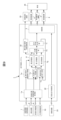
- FIG. 1 is a schematic diagram showing a configuration of a vehicle cruise control system according to a first embodiment of the present invention
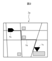
- FIG. 2 is an explanatory diagram illustrating a map as an example of a driving environment in the first embodiment of the present invention.
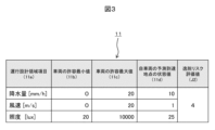
- FIG. 2 is an explanatory diagram illustrating the relationship between items and numerical values of an operation design domain (ODD) in the first embodiment of the present invention.
- FIG. 4 is a flowchart illustrating an operation according to the first embodiment of the present invention.
- FIG. 4 is an explanatory diagram illustrating the operation when traveling on a general public road in the first embodiment of the present invention.
- FIG. 11 is an explanatory diagram illustrating a state of a work site in a second embodiment of the present invention.
- FIG. 4 is a schematic diagram showing a vehicle cruise control system according to a second embodiment of the present invention.
- FIG. 13 is an explanatory diagram illustrating a state of a work site in a third embodiment of the present invention.
- FIG. 11 is a schematic diagram showing a vehicle cruise control system according to a third embodiment of the present invention.
- an embodiment of the present invention will be described using as an example the driving control of an autonomous vehicle that executes an autonomous driving service in which an automobile carrying passengers drives itself (autonomously) to any desired location.
- the present invention can also be applied to the design of general services related to industrial machinery capable of autonomous driving in a specific environment, and the application of the present invention is not limited to automobiles.
- the first embodiment employs the configurations described in the claims, for example, claims 1 to 5.
- the configuration of the first embodiment makes it possible to provide a vehicle driving control system that can prevent the vehicle from departing from the operational design domain (ODD), reduce the impact of the vehicle's departure avoidance actions on the driving of other vehicles, suppress deterioration of traffic flow, and further improve the evaluation of the autonomous driving service provided by the vehicle.
- ODD operational design domain
- the controlled object is a vehicle such as an automobile, so the "controlled object” will be described as a “vehicle”, but the present invention can be applied to things other than vehicles, so in such cases it should be read as a "controlled object”.
- the expression "controlled object” is used as is in the drawings.
- the vehicle driving control system 1 is equipped with a vehicle-related information acquisition unit 1a, a vehicle state prediction unit 1b, a traffic situation prediction unit 1c, and a first evaluation unit 1d, and is a system that determines the behavior (hereinafter, sometimes referred to as driving behavior) of a vehicle, which is a host vehicle 2.
- the driving control system 1 is also connected to the steering mechanism 4, vehicle drive mechanism (internal combustion engine or electric motor) 5, and braking mechanism 6 via a control signal line (Sout).
- the steering mechanism 4, vehicle drive mechanism 5, and braking mechanism 6 are controlled according to control signals from the driving control system 1 sent from the control signal line (Sout), causing the host vehicle 2 to travel along any desired driving route, acceleration/deceleration, vehicle speed, etc.
- the configuration of the vehicle driving control system 1 will be described.
- the following configuration is a functional block, and is executed by a computer activated by well-known logic circuits and software.
- Examples of computer processors include a CPU (Central Processing Unit) and a GPU (Graphics Processing Unit), but it is also possible to use semiconductor devices with other computing functions as long as they perform the specified calculation processing.
- the vehicle-related information acquisition unit 1a has a function of acquiring vehicle-related information related to driving state information of the vehicle 2 and surrounding environment information of the vehicle 2.
- the vehicle-related information is acquired from a map information acquisition device 7, a positioning device 8, a state measurement device 9, an external environment recognition device 10, etc., which are connected to the driving control system 1 via an input signal line (Sin).
- Vehicle-related information includes at least surrounding environment information and driving condition information.
- the surrounding environment information includes a map of the driving environment, the planned driving route of the vehicle 2, road conditions and signs around the vehicle 2, the positions of surrounding vehicles and other moving objects, speed and other status values, the size of the vehicles and moving objects, and the types of pedestrians, bicycles, motorcycles, etc. It is also possible to obtain other environmental information.
- the driving state information includes state values such as the speed, acceleration/deceleration, steering angle, front/rear, left/right, and up/down acceleration, roll, and pitch of the vehicle 2. It is also possible to obtain state values other than these.
- the vehicle-related information acquisition unit 1a also has a function for recognizing information about the lane on which the vehicle 2 is traveling (number of lanes, type of lane) from both map information and the position information of the vehicle 2, and is thus able to acquire information such as the number of lanes and type of lane.
- the map information acquisition device 7 has a function of acquiring information such as a map 7a of the driving environment as shown in Figure 2, the position 7b of the vehicle 2 within the map 7a, a destination 7c of the autonomous driving service, and a driving route 7d from the position 7b of the vehicle 2 to the destination 7c.
- the travel route 7d may be calculated by the map information acquisition device 7, or, alternatively, a travel route calculated by an external operation planning system (not shown) connected to the map information acquisition device 7 may be acquired, and the map information acquisition device 7 may combine the map 7a and the acquired travel route 7d.
- the positioning device 8 has a function of acquiring detailed coordinate position and direction information, such as the position 7b of the vehicle 2 shown in FIG. 2, by using a satellite positioning system or the like.
- the state measurement device 9 has a function of acquiring state quantities such as the vehicle speed, forward/backward, left/right, and up/down acceleration, and angular velocities and angles of roll, pitch, yaw, and the like of the host vehicle 2.
- state measurement device 9 can be configured using an inertial measurement unit (IMU).
- IMU inertial measurement unit
- the external environment recognition device 10 has a function of acquiring three-dimensional shape and color information of the surrounding environment of the vehicle 2, and is configured, for example, by a 3D LiDAR (Light Detection And Ranging) or a stereo camera. In addition, it may be configured using a plurality of 3D LiDARs or stereo cameras.
- 3D LiDAR Light Detection And Ranging
- the vehicle-related information acquisition unit 1a can estimate state values such as the position and speed of surrounding vehicles and other moving objects, identify the size of the vehicles and moving objects, and distinguish between types of vehicles such as pedestrians, bicycles, and motorcycles, based on information from the external environment recognition device 10.
- the vehicle state prediction unit 1b acquires vehicle-related information regarding the driving state information of the vehicle 2 and the surrounding environment information of the vehicle from the vehicle-related information acquisition unit 1a, and calculates a predicted value of the driving behavior of the vehicle 2 from the current time to the predicted time (T1) based on this information.
- the predicted driving information which is a predicted value of the driving behavior, is a time-series change value of the driving route, including the position information of the vehicle 2, the vehicle speed, acceleration/deceleration, attitude, etc., up to the predicted time (T1) ahead. Note that there may also be change values that are not time-series.
- the prediction of the driving behavior of the vehicle 2 is performed, for example, by a numerical calculation based on the equation of motion of the vehicle 2.
- the predicted time (T1) can vary from a few seconds to a few minutes and can be set appropriately.
- predicted times (T2 to T4) described below may be set in chronological order from the current time, or may be set to the same time. In essence, they are predicted times at which the control described below is established.
- the traffic condition prediction unit 1c has a function of predicting changes in traffic conditions caused by the impact that the driving behavior of the vehicle 2 has on other vehicles, based on state values such as the positions and speeds of surrounding vehicles and other moving bodies acquired from the vehicle-related information acquisition unit 1a and predicted values of the driving behavior of the vehicle 2 acquired from the vehicle state prediction unit 1b.
- time-series change values such as the driving route, vehicle speed, acceleration/deceleration, and attitude, including the position information of surrounding vehicles traveling mainly in front of or behind the vehicle 2 or in adjacent lanes, from the current time to the predicted time (T2) ahead, are predicted.
- the behavior selected by the drivers of the nearby vehicles can be modeled using a formula and predicted by numerical calculation of this model.
- the system predicts driving behavior, such as acceleration/deceleration and steering operations, to avoid contact in response to the approach of the vehicle 2 or other surrounding vehicles.
- the prediction time (T2) is, for example, several seconds.
- the error inherent in the formulas used in the numerical values calculated from the equations of motion and the behavior model may be calculated using a probability distribution, and the variance in the driving behavior of each vehicle may be expressed using a probability distribution.
- the first evaluation unit 1d has a function of evaluating the traffic flow based on the travel route including the position information of the surrounding vehicles up to the predicted time (T2) ahead, and the time-series change values of the vehicle speed, acceleration/deceleration, and attitude received from the traffic condition prediction unit 1c.
- the evaluation value (J1) of the traffic flow is calculated, for example, by the following "Equation 1".
- i is the vehicle number
- N is the total number of surrounding vehicles
- t is the start time
- h is the predicted time T2
- Vi is the speed of each vehicle.
- J1 the traffic flow evaluation value shown in “Equation 1” tends to be large when surrounding vehicles accelerate or decelerate. This is the evaluation value used to determine whether congestion is likely to occur.
- the traffic flow evaluation value (J1) becomes a large value, and it is considered that the traffic flow of the nearby vehicles has worsened (a traffic jam has been caused).
- the first evaluation unit 1d calculates the evaluation value (J1) based on at least the magnitude of acceleration and deceleration of other surrounding vehicles around the host vehicle 2 and the distance between the host vehicle 2, based on the traffic conditions predicted by the traffic condition prediction unit 1c.
- a term expressing the degree of vehicle proximity according to the distance between the host vehicle 2 and the surrounding vehicles may be added to the traffic flow evaluation value (J1).
- the operation design area prediction unit 1e has a function of predicting an environmental state related to the operation design area (ODD) of the vehicle 2 using the surrounding environment information of the vehicle 2 acquired from the vehicle-related information acquisition unit 1a.
- the environmental state information related to the operation design area (ODD) of the vehicle 2 may be predicted using the predicted driving route of the vehicle 2 acquired from the vehicle state prediction unit 1b.
- environmental state information after the predicted time (T3) includes weather such as precipitation and wind speed on the route traveled by the vehicle 2, road gradient, whether or not there is a speed limit due to traffic regulations, sunlight conditions, etc.
- the prediction of environmental state information regarding the operation design domain (ODD) after the predicted time (T3) of the vehicle 2 may be calculated as an expected value from past statistical values, or may be calculated as a probability distribution of statistical values.
- the second evaluation unit 1f has a function of comparing state information of the operation design area (ODD) at the predicted destination of the vehicle 2 after the predicted time (T4) predicted by the operation design area prediction unit 1e with predicted driving information such as driving route, vehicle speed, acceleration/deceleration, posture, etc., including position information of the vehicle 2 after the predicted time (T1) obtained from the vehicle state prediction unit 1b, to evaluate the deviation risk, which is the degree to which the vehicle 2 deviates from the operation design area (ODD).
- ODD operation design area
- the operation design domain table 11 shows operation design domain items 11a of the host vehicle 2, and for these items, minimum allowable values 11b and maximum allowable values 11c of the host vehicle 2 are preset. This shows the range of environmental conditions for the automatic driving function of the host vehicle 2 to operate normally.
- the state value of the operation design domain item 11a for the predicted arrival point of the host vehicle after the predicted time (T4) and the deviation risk evaluation value (J2) are shown. It goes without saying that the operation design domain items 11a can be set to items other than those shown.
- (1) precipitation, (2) wind speed, and (3) illuminance are set as examples of operation design area items 11a.
- “Deviation” from the operational design domain (ODD) occurs when, after the predicted time (T4) shown in the operational design domain table 11, the state value 11d of the operational design domain item of the predicted destination where the vehicle 2 is located exceeds the range indicated by the minimum allowable value 11b and maximum allowable value 11c of the vehicle 2. In other words, deviation from the operational design domain (ODD) indicates that the automatic driving function of the vehicle 2 cannot operate normally.
- the evaluation value (J2) of the risk of deviation from the operation design area is evaluated based on whether the state value 11d of the operation design area item of the predicted destination point where the vehicle 2 will be located after the predicted time (T4) is within the range between the minimum allowable value 11b and the maximum allowable value 11c of the vehicle 2 in the operation design area table 11, and how close it is to the minimum allowable value 11b or the maximum allowable value 11c.
- the evaluation value (J2) of the risk of deviation is calculated, for example, by the following "Equation 2".
- j is an item in the operational design domain (ODD)
- M is the number of items in the operational design domain (ODD)
- Sjmin is the minimum allowable value of item j in the operational design domain (ODD)
- Sjmax is the maximum allowable value of item j in the operational design domain (ODD)
- OjT4 is the state value of item j in the operational design domain (ODD) at the predicted time (T4).
- kj is a coefficient for adjusting the risk value between each item in the operational design domain (ODD).
- the deviation risk evaluation value (J2) will be a large value, indicating a high deviation risk. Also, if the state value OjT4 is calculated by the operation design area prediction unit 1e using probability density, the deviation risk evaluation value (J2) may be calculated using the maximum expected value for the allowable value.
- the third evaluation unit 1g has a function of calculating an evaluation value for the autonomous driving service, for example, an evaluation value (J3) of a key performance indicator (KPI), using time-series change values of the driving route, vehicle speed, acceleration/deceleration, attitude, etc., including the position information of the vehicle 2 up to the predicted time (T1) ahead, acquired from the vehicle state prediction unit 1b.
- the evaluation value for the autonomous driving service can be said to evaluate the appropriateness of the autonomous driving service.
- evaluation value for autonomous driving services is not limited to key performance indicators (KPIs), and other indicators can also be used, and can be selected as needed.
- KPIs key performance indicators
- Key performance indicators are indicators used to evaluate whether driving behavior is more appropriate for an autonomous driving service.
- Key performance indicators include the time required for the vehicle 2 to travel from its position 7b to its destination 7c as shown in Figure 2, as well as the operating profit and vehicle operation rate obtained by performing autonomous driving.
- operating profit and vehicle operation rate are important evaluation items for the operation of commercial vehicles, and therefore are of high importance.
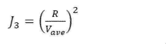
- the evaluation result of the third evaluation unit 1g is the evaluation value (J3) of the key performance indicator (KPI) related to the time required to travel to the destination, which is calculated, for example, by the following "Equation 3.”
- R is the route distance of the travel route from the position 7b of the vehicle 2 to the destination 7c as shown in FIG. 2
- “Vave” is the predicted average vehicle speed until the vehicle 2 reaches the destination 7c. Note that “R” may be the straight-line distance from the position 7b of the vehicle 2 to the destination 7c.
- the evaluation value (J3) of the key performance indicator (KPI) is the square of the time required for the vehicle 2 to travel from its position 7b to its destination 7c as shown in Figure 2, and a larger evaluation value (J3) of the key performance indicator (KPI) means a lowering of the key performance indicator (KPI).
- the traffic evaluation unit 1h has a function of calculating a traffic evaluation value (J) indicating a change in overall traffic conditions caused by the driving behavior of the vehicle 2, using the traffic flow evaluation value (J1) of the first evaluation unit 1d, the deviation risk evaluation value (J2) of the second evaluation unit 1f, and the key performance indicator (KPI) evaluation value (J3) of the third evaluation unit 1g.
- the traffic evaluation value (J) is calculated, for example, by the following "Equation 4".
- a priority order for improving the traffic evaluation (J) may be set for each evaluation value (J1 to J3). In other words, a priority order may be determined in advance for which of the evaluation values (J1 to J3) should be changed to efficiently improve the traffic evaluation (J).
- the driving plan generation unit 1i has a function of creating a driving plan for the vehicle 2 based on the traffic evaluation value (J) of the traffic evaluation unit 1h, which reduces the adverse impact of the vehicle 2 on traffic flow for other vehicles while maintaining the evaluation value (J2) of the risk of deviation from the operation design domain (ODD) of the vehicle 2 at a predetermined evaluation value, and further improves the autonomous driving service operated by the vehicle 2.
- the deviation risk evaluation value (J2) can be large or small depending on the driving behavior of the vehicle 2, so it is expressed as a predetermined evaluation value. In other words, it is assumed that the driving behavior will be determined by giving priority to the evaluation value (J3) of the key performance indicator (KPI) in a state where deviation does not occur even if there is a deviation risk.
- the driving plan obtained by the driving plan generation unit 1i is the planned driving route of the vehicle 2 up to the final planned time (T5) and the time series values of the vehicle speed, acceleration/deceleration values, steering values, etc., which are the control inputs required to realize the planned driving route.
- the driving plan generation unit can create a driving plan that takes into account the traffic flow evaluation value (J1) to suppress the acceleration and deceleration of other surrounding vehicles due to the driving behavior of the host vehicle 2, while maintaining a predetermined distance between the host vehicle and other surrounding vehicles.
- J1 the traffic flow evaluation value
- the driving plan generation unit 1i has a function of calculating a control input value that makes the traffic evaluation value (J) expressed by "Equation 4" of the traffic evaluation unit 1h a predetermined value, for example, a minimum value.
- a control input value that makes the traffic evaluation value (J) expressed by "Equation 4" of the traffic evaluation unit 1h a predetermined value, for example, a minimum value.
- One example of the calculation method is model predictive control. An example of a calculation method using this model predictive control will be explained using the flowchart in Figure 4.
- a control input value is calculated so that the traffic evaluation value (J) calculated by the traffic evaluation unit 1h is smaller than that of the previous step, and the process starts from "Step S101" using the control input value.
- step S102 the vehicle-related information acquisition unit 1a acquires vehicle-related information required for predicting the host vehicle 2 and the surrounding environment. After acquiring the vehicle-related information, the process proceeds to step S103.
- step S103 the vehicle state prediction unit 1b predicts the driving behavior of the vehicle 2, and the traffic condition prediction unit 1c predicts the surrounding environment information and the driving behavior of surrounding vehicles. Once the driving behavior of the vehicle 2, the surrounding environment information, the driving behavior of the surrounding vehicles, etc. have been predicted, the process proceeds to step S104.
- step S104 the operation design area prediction unit 1e predicts environmental state information related to the operation design area (ODD) for the vehicle 2. After predicting the environmental state information of the operation design area (ODD), the process proceeds to steps S105 and S106.
- ODD operation design area
- step S105 the first evaluation unit 1d obtains an evaluation value (J1) of the traffic flow, and similarly, the third evaluation unit 1g obtains an evaluation value (J3) of the key performance indicator (KPI).
- step S106 the second evaluation unit 1f obtains an evaluation value (J2) of the deviation risk. After obtaining the respective evaluation values (J1, J2, J3), the process proceeds to step S107.
- step S107 if the deviation risk evaluation value (J2) of the operation design domain (ODD) is greater than a predetermined value, a notification that a deviation state has occurred is issued to the driver of the vehicle 2. If the deviation risk evaluation value (J2) is less than the predetermined value, the process proceeds to step S108.
- step S107 by notifying the driver in advance of a departure from the operational design domain (ODD), even if the driver is delegated driving authority of the vehicle 2 at the time of the departure, the driver can continue driving the vehicle 2 promptly.
- ODD operational design domain
- the operation design area deviation risk notification unit 1j shown in FIG. 1 can issue a notification via the operation design area deviation risk display device 1k, which can notify the driver.
- the notification process in step S107 is completed, the process proceeds to step S108.
- step S108 the traffic evaluation unit 1h calculates a traffic evaluation value (J) based on "Equation 4" using the traffic flow evaluation value (J1) of the first evaluation unit 1d obtained in steps S105 and S106, the deviation risk evaluation value (J2) of the second evaluation unit 1f, and the key performance indicator (KPI) evaluation value (J3) of the third evaluation unit 1g.
- the traffic evaluation value (J) is obtained, the process proceeds to step S109.
- step S109 if the driving plan generation unit 1i determines that the traffic evaluation value (J) has become sufficiently small (Yes judgment), or determines that the difference from the traffic evaluation value (J) of the previous step is small (Yes judgment), the driving plan generation unit 1i determines that the control input value sufficiently improves the traffic evaluation value (J) and proceeds to step S110.
- the traffic evaluation value (J) may be controlled so that it settles at a predetermined value, for example, the minimum traffic evaluation value (J), while searching for a control input value as in step S111 described below.
- step S109 determines in step S109 that the current traffic evaluation value (J) is worse than the traffic evaluation value of the previous step (No)
- the process proceeds to step S111.
- step S110 since the determination in step S109 is Yes, the control input value is output from the driving schedule generating unit 1i to the control unit 3, and the process returns to step 102 again to repeat the above-mentioned control steps.
- step S111 since the result of the determination in step S109 is No, a control input value that can improve the traffic evaluation value (J) of one step before is searched for, and the calculation in step S103 is repeated again using the control input value.
- the traffic evaluation value (J) is controlled so as to converge to a predetermined value, preferably a minimum value, while searching for a control input value.
- This is a feedback system that is returned from the driving plan generation unit 1i to the vehicle state prediction unit 1b in FIG. 1.
- the traffic evaluation value (J) becomes a predetermined value (for example, a minimum value)
- the control input value at this time is confirmed and becomes the confirmed control input value.
- control input values for each evaluation value (J1 to J3) may be searched for using multi-objective optimization.
- the evaluation value (J2) of the deviation risk in the operational design domain (ODD) may be set as a constraint condition within the range shown in the operational design domain table 11 in FIG. 3, and the control input value may be searched for in step S111.
- the control unit 3 calculates a control amount for realizing a traffic evaluation value (J) based on the confirmed control input values, which are time-series values of the vehicle speed value, acceleration/deceleration value, and steering value obtained from the driving plan generation unit 1i, and outputs the calculated control amount as a control signal (Sout) to the steering mechanism 4, the vehicle drive mechanism 5, and the braking mechanism 6.
- J traffic evaluation value
- the vehicle 2 and the surrounding vehicle 12a are traveling in the first driving lane 13a, and the surrounding vehicle 12b is traveling in the adjacent second driving lane 13b.
- the first driving lane 13a and the second driving lane 13b are located at an intersection equipped with traffic lights 14.
- the first driving lane 13a is a straight lane
- the second driving lane 13b is a right-turn-only lane.
- routes to the destination 7c there are two candidate routes: a route 15a that passes through the first driving lane 13a, and a route 15b that passes through the second driving lane 13b.
- the second evaluation unit 1f calculates an evaluation value (J2) of the risk of deviation from the operation design domain (ODD) of the vehicle 2. If the evaluation value (J2) of the risk of deviation is high, when the vehicle 2 decelerates to avoid deviation from the operation design domain (ODD), the surrounding vehicle 12a following behind is also required to rapidly decelerate, and the evaluation value (J1) of the traffic flow is increased.
- the host vehicle 2 selects to change lanes to the second driving lane 13b, which can suppress the acceleration/deceleration of the surrounding vehicle 12a following behind caused by the driving behavior of the host vehicle 2 based on "Equation 1," thereby lowering the traffic flow evaluation value (J1) and lowering the deviation risk evaluation value (J2). In this way, the host vehicle 2 can avoid the risk of deviation from the operation design domain (ODD) by changing lanes to the second driving lane 13b.
- ODD operation design domain
- the driving route 15b to the destination 7c will be longer than the driving route 15a when the vehicle 2 takes the first driving lane 13a.
- the time required to reach the destination 7c will be longer, and the key performance indicator (KPI) of the autonomous driving service will decrease.
- the second evaluation unit 1f calculates the deviation risk evaluation value (J2) of the operation design domain (ODD) of the vehicle 2, and when the deviation risk evaluation value (J2) is relatively high, the traffic flow evaluation value (J1) of the first evaluation unit 1d and the key performance indicator (KPI) evaluation value (J3) of the third evaluation unit 1g are taken into account, and the driving behavior described below can be executed.
- deviation from the operational design domain is avoided while maintaining a relatively high deviation risk evaluation value (J2) for the ODD, and the vehicle 2 is accelerated or decelerated based on the traffic flow evaluation value (J1) and the key performance indicator (KPI) evaluation value (J3) to adjust the vehicle 2's travel speed and minimize the impact on surrounding vehicles 12a.
- the first embodiment was described with respect to an autonomously driving automobile, but the second embodiment is an example in which the present invention is applied to a dump truck used at construction sites and the like to transport soil and sand.
- the second embodiment employs the configuration described in the claims, for example claim 6.
- FIG. 6 shows an operation in which a shovel 17 placed on a work platform 18 excavates soil on the work platform 18 and loads the soil onto an automatically-operated dump truck 19 that automatically stops in a parking area 21.
- the autonomous dump truck 19 is assumed to be equipped with the driving control system shown in FIG. 1.
- the shovel 17 shown in FIG. 6 moves backwards while excavating the excavation area 20, which is the work platform 18 under the front feet. Therefore, the position of the stopping area 21 suitable for loading changes each time the shovel 17 excavates soil and moves backwards.
- the autonomous dump truck 19 may have difficulty stopping. For example, this may be the case when there is a huge rock in the stopping area 21. In such a case, the autonomous dump truck 19 may not be able to stop in an appropriate stopping area 21. As a result, the excavator 17 may not be able to load the excavated soil and sand onto the autonomous dump truck 19, which may result in a decrease in the work efficiency of the entire construction work site 16.
- the driving control system in FIG. 7 is characterized in that it includes a steering device 23 and an emergency driving control unit 22 connected to the steering device 23 via a signal line.
- the driving plan generating unit 1i determines that there is a risk that the autonomous dump truck 19 will deviate from the operation design area (ODD) and determines that it is not possible to generate a driving plan for the autonomous dump truck 19 that maintains or improves the previous traffic evaluation value (J), it has a function of determining that the autonomous dump truck 19 will ultimately deviate from the operation design area (ODD) and sending deviation determination information to the control unit 3.
- the control unit 3 has a function of switching the driving control of the autonomous dump truck 19 to be executed by the emergency driving control unit 22 upon receiving deviation determination information.
- the steering device 23 is, for example, a driving operation device equipped with a steering wheel, an accelerator pedal, a brake pedal, etc. for remote driving, which is installed at a location away from the construction work site and is wirelessly connected to the autonomous dump truck 19.
- the driving operation amount of the steering device 23 is transmitted to the emergency driving control unit 22 via a wireless communication section, and the emergency driving control unit 22 transmits the received driving operation amount to the control unit 3.
- the second evaluation unit 1f determines that the rock deviates from the flatness required for the stopping area 21, which is an item of the operation design domain (ODD) of the autonomously driven dump truck 19.
- the driving plan generation unit 1i determines that it is not possible to generate a driving plan for the autonomously driven dump truck 19 that maintains or improves the traffic evaluation value (J) from the previous traffic evaluation value (J).
- the driving plan generating unit 1i determines that the autonomously driven dump truck 19 will ultimately deviate from the operation design domain (ODD) and transmits deviation determination information to the control unit 3.
- the control unit 3 receives the deviation determination information and switches the driving control of the autonomously driven dump truck 19 to the emergency driving control unit 22.
- the driving control of the autonomous dump truck 19 is based on remote operation by the steering device 23. Then, based on the judgment of the driver in the remote cab, the operation of the autonomous dump truck 19 at the construction work site 16 is temporarily changed, the parking area 21 is set to a location that avoids huge rocks, and the driving of the autonomous dump truck 19 is remotely controlled. This makes it possible to prevent a decrease in the work efficiency of the entire construction work site 16.
- the emergency driving control unit 22 also has a degenerate control function that can autonomously respond to emergencies without using the steering device 23, and can also autonomously generate a driving plan for emergency evacuation.
- the first embodiment was described with respect to an autonomously driving automobile, but the third embodiment is an example in which the present invention is applied to an autonomous transport vehicle that transports luggage used in a logistics warehouse or the like.
- the third embodiment employs the configuration described in the claims, for example, claim 7.
- an automated guided vehicle 25 transports luggage stored on a shelf 26 from the shelf 26 to a shipping area 27 in order to ship the luggage.
- the automated guided vehicle 25 is assumed to be equipped with the driving control system shown in FIG. 7.
- An unmanned transport area 30 is set as the operation design domain (ODD) of the automated transport vehicle 25, and the unmanned transport area 30 is designed as an area where no vehicles other than the automated transport vehicle 25 can enter, except for the shipping area 27.
- ODD operation design domain
- the second evaluation unit 1f of the driving control system shown in FIG. 7 determines that the worker 31's entry may cause the automated guided vehicle 25 to deviate from the operational design domain (ODD).
- ODD operational design domain
- the emergency driving control unit 22 makes an emergency stop of the automated guided vehicle 25 or switches to a degenerate mode, such as a low-speed driving mode.
- a degenerate mode such as a low-speed driving mode.
- the driving behavior of the automated guided vehicle 25 is suppressed by the control unit 3, which results in a problem of a decrease in the efficiency of luggage transportation at the logistics warehouse 24.
- the driving control system in FIG. 9 is characterized by having an operation design domain change proposal unit 32.
- the automatic driving of the automated guided vehicle 25 is basically performed by the driving control system shown in FIG. 1, so a detailed description will be omitted here.
- an operation design domain change proposing unit 32 is provided, and the operation design domain change proposing unit 32 is connected to a proposal notification device 33 via a communication line.
- the operation design area change proposal unit 32 has a function of retaining the accumulated value of the number of deviations in the operation design area (ODD), and also has a function of sending a change proposal for an item in the operation design area (ODD) to the proposal notification device 33 when the accumulated value of the number of deviations exceeds a predetermined threshold.
- the proposal notification device 33 has a function to notify the manager of proposed changes to items in the operation design domain (ODD).
- the notification method can be visual or auditory.
- a typical automated guided vehicle driving control system has an issue in that every time a worker 31 enters the unmanned transport area 30, the driving behavior of the automated guided vehicle 25 is restricted, resulting in a decrease in the efficiency of transporting luggage.
- the vehicle-related information acquisition unit 1a can detect in advance the intrusion of a worker 31 into the unmanned transport area 30. Therefore, the operation design area prediction unit 1e predicts the intrusion of the worker 31, and based on this prediction, the driving plan generation unit 1i can calculate a driving plan that avoids deviation from the operation design area (ODD) while suppressing adverse effects on other automated transport vehicles and also suppresses a decrease in baggage transport efficiency, which is a key performance indicator (KPI).
- ODD operation design area
- KPI key performance indicator
- the intrusion of the worker 31 into the unmanned transport area 30 is assumed to be a necessary action in advance, thereby improving the efficiency of transporting luggage.
- the operation design area change proposal unit 32 accumulates the number of deviations of the worker that have been determined to be deviations by the second evaluation unit 1f.
- the operation design area change proposal unit 32 functions to derive a proposal to add "permission to enter" the operator 31 to the operation design area (ODD).
- the threshold is, for example, several times. Setting the accumulated number of deviations in this way is a judgment that the operator 31 is deemed to be entering the unmanned transport area 30 as necessary and is repeating the actions necessary for transporting luggage.
- the operation design area change proposal unit 32 sends the derived proposal to the proposal notification device 33, and notifies, for example, the manager (operation design area designer) of the proposed change to the operation design area (ODD).
- the manager (operation design area designer) adds permission for the worker 31 to enter the operation design area (ODD) of the automated guided vehicle 25, and updates the driving control system as a new operation design area (ODD).
- the driving plan generation unit 1i can generate a driving plan that improves the baggage transport efficiency, which is a key performance indicator (KPI), while minimizing the impact on other automated transport vehicles, without considering avoiding deviation from the operation design area (ODD).
- KPI key performance indicator
- the present invention is not limited to the above-mentioned embodiments, but includes various modified examples.
- the above-mentioned embodiments have been described in detail to clearly explain the present invention, and are not necessarily limited to those having all of the configurations described. It is also possible to replace part of the configuration of one embodiment with the configuration of another embodiment, and it is also possible to add the configuration of another embodiment to the configuration of one embodiment. It is also possible to add, delete, or replace other configurations with respect to the configuration of each embodiment.
- 1...cruising control system 1a...control object related information acquisition unit, 1b...control object state prediction unit, 1c...traffic condition prediction unit, 1d...first evaluation unit, 1e...operation design area prediction unit, 1f...second evaluation unit, 1g...third evaluation unit, 1h...traffic evaluation unit, 1i...driving plan generation unit, 1j...operation design area deviation risk notification unit, 1k...operation design area deviation risk display device, 2...vehicle, 3...control unit, 4...steering mechanism, 5...vehicle drive mechanism, 6...braking mechanism, 7...map information acquisition device, 8...positioning device, 9...state measurement device, 10...external environment recognition device, 11...operation design area table, 12a, 12b...surrounding vehicles, 13a, 13b...lanes, 14...traffic lights, 15a, 15b...route, 16...work site, 17...shovel, 18...work platform, 19...autonomous dump truck, 20...digging area, 21...parking area, 22...emergency driving control unit, 23...steer
Landscapes
- Engineering & Computer Science (AREA)
- Automation & Control Theory (AREA)
- Mechanical Engineering (AREA)
- Transportation (AREA)
- Physics & Mathematics (AREA)
- General Physics & Mathematics (AREA)
- Business, Economics & Management (AREA)
- Human Computer Interaction (AREA)
- Remote Sensing (AREA)
- Radar, Positioning & Navigation (AREA)
- Tourism & Hospitality (AREA)
- Mathematical Physics (AREA)
- Economics (AREA)
- Theoretical Computer Science (AREA)
- General Business, Economics & Management (AREA)
- Strategic Management (AREA)
- Primary Health Care (AREA)
- Marketing (AREA)
- Human Resources & Organizations (AREA)
- General Health & Medical Sciences (AREA)
- Health & Medical Sciences (AREA)
- Traffic Control Systems (AREA)
- Control Of Driving Devices And Active Controlling Of Vehicle (AREA)
Abstract
自車両が運行設計領域から逸脱するのを回避し、且つ自車両の逸脱回避行動による他車両の走行への影響を低減して交通流の悪化を抑制し、更に、自車両が提供する自動運転サービスの評価を向上することが可能な車両の走行制御システム、及び車両の走行制御方法を提供する。 自車両が他の周辺車両に与える影響に基づいて求められた予測交通状況から自車両と他の周辺車両の交通流を評価し(S105)、運行設計領域の環境状態情報と予測走行情報を用いて、車両が前記運行設計領域を逸脱する逸脱リスクを評価し(S106)、予測走行情報を用いて、自車両が目的地まで走行する際の自動運転サービスの適切性を評価し(S105)、交通流の評価値、逸脱リスクの評価値、及び自動運転サービスの適切性の評価値を統合して、自車両が走行する際の総合的な交通評価値を算出し(S108)、交通評価値に基づいて自車両の走行計画を繰り返し作成し(S109、S111)、交通評価値が所定の値に達すると走行計画を確定し(S109、S110)、確定された走行計画に基づいて、自車両の走行行動を制御する。
Description
本発明は、自動車等の車両を自動運転させる車両の走行制御システム、及び車両の走行制御方法に関する。
近年、自動車、搬送ロボット、建設機械等の様々な産業用車両を自動走行させる走行制御システムが開発されている。産業用車両を自動走行させることにより、現場の無人化によるコスト低減や、作業効率の均一化による現場の作業効率の改善が期待される。また、自動車においては、自動運転化により渋滞の改善や事故の低減が期待されている。
車両の自動運転を実現する走行制御システムの構成や仕様は、対象とする車両や運行する環境によって多種多様であるため、自動運転を行う走行制御システムの動作を保証する環境条件である「運行設計領域(ODD:Operational Design Domain)」を定義することが必要である。
ここで、「環境条件」とは、自動運転が可能な天候、道路形状、路面状態、通信インフラの使用可否等である。尚、これら以外の項目が設定される場合もあり、車両の種類、走行環境によって適切に設定されるものとなっている。
自動運転車両(以下、車両)においては、自動運転で走行中に運行設計領域(ODD)を逸脱する場合がある。例えば、雨天時の降水量が運行設計領域(ODD)で予め定めた許容降水量を超えることがある。したがって、運行設計領域(ODD)を逸脱すると、自動運転のための走行制御システムが、正常な動作を保証できなくなる恐れがある。
このため、運行設計領域(ODD)を逸脱した場合は、車両を速やかに安全な状態へ移行する機能が必要である。もちろん、これ以外の環境条件の変動によっても、運行設計領域(ODD)を逸脱することはいうまでもない。例えば、自動運転中に走行車線を変更する場合において、運行設計領域(ODD)の逸脱が予測される状況では、自車両の走行車線の変更による交通流への悪影響を低減することが必要である。
自動運転中における走行車線の変更に関する運行設計領域(ODD)の逸脱については、以下に述べる特開2022-53296号公報(特許文献1)に記載された、走行制御システムが知られている。
例えば、自動運転中に走行車線を変更する場合において、隣接車線の所定領域に他車両が存在せず、走行車線の変更を開始できた場合であっても、その後の走行環境の変化によって、他車両との接近等が新たに生じて交通流への悪影響(例えば、渋滞)が懸念される。
このような課題に対応するために、特許文献1の走行制御システムにおいては、運行設計領域(ODD)の逸脱が予測される場合に、走行車線の変更の可否判定の基準として、通常時の第1の所定領域(走行方向の車間長)より広い第2の所定領域(走行方向の車間長)が設定されている。
そして、第1の所定領域からは外れているものの、それより広い第2の所定領域に他車両が存在するような臨界的条件下では、走行車線の変更が開始されず、車線内走行が維持される。このため、その後に走行環境が変化しても、走行車線の変更による交通流への悪影響を抑制するうえで有利である。
一方、第2の所定領域に他車両が存在しないような非臨界的条件下では、その後に走行環境が変化しても、隣接車線を走行する他車両との接近が生じる可能性は低く、むしろ、走行車線の変更を開始して、先行他車両との設定車間距離での追従走行を離脱する方が、交通流への影響を低減できるので走行車線の変更の機会喪失の回避が見込めるものである。
ところで、特許文献1の走行制御システムでは、第1の所定領域より広い第2の所定領域に自車両を移動させるように制御するため、一般公道における一車線の道路では用いることができないという課題を有している。
また、一般公道で複数車線が存在する道路において、そのうちの1本が右折専用レーンとなっている場合では、運行設計領域(ODD)の逸脱を回避する時に、その標示(専用レーン)を考慮しない判断を行うことがある。
したがって、右折専用レーンを広い第2の所定領域であると判断して、右折専用レーンに退避してしまうと、右折しかできないために目的の走行経路に復帰できない場合があり、目的地に到着するまでの所要時間が増加するなどして車両の移動効率が低下する。
この移動効率が低下すると、自動運転サービスの評価、例えば、重要業績評価指標(KPI/Key Performance Indicator)が低下するといった新たな課題が生じることになる。
本発明の目的は、自車両が運行設計領域(ODD)から逸脱するのを回避し、且つ自車両の逸脱回避行動による他車両の走行への影響を低減して交通流の悪化を抑制し、更に、自車両が提供する自動運転サービスの評価を向上することが可能な車両の走行制御システム、及び車両の走行制御方法を提供することにある。
本発明は、
制御対象の走行状態、及び制御対象の周辺環境に関する制御対象関連情報を取得する制御対象関連情報取得部と、
制御対象関連情報取得部が取得した制御対象関連情報に基づいて、制御対象の走行情報を予測する制御対象状態予測部と、
制御対象関連情報取得部が取得した制御対象関連情報と制御対象状態予測部が予測した制御対象の予測走行情報に基づき、制御対象の走行行動が与える影響に基づく交通状況を予測する交通状況予測部と、
交通状況予測部が予測した交通状況を評価する第1評価部と、
制御対象関連情報取得部が取得した制御対象の周辺環境情報を用いて、制御対象の運行設計領域に関する環境状態情報を予測する運行設計領域予測部と、
運行設計領域予測部が予測した運行設計領域の環境状態情報と、制御対象状態予測部が予測した制御対象の予測走行情報を用いて、制御対象が運行設計領域を逸脱する逸脱リスクを評価する第2評価部と、
制御対象状態予測部の予測走行情報を用いて、制御対象が目的地まで走行する際の自動運サービスの適切性を評価する第3評価部と、
第1評価部の評価結果、第2評価部の評価結果、及び第3評価部の評価価結果を用いて、制御対象が走行する際の総合的な交通評価値を算出する交通評価部と、
交通評価部の交通評価値に基づき、前期制御対象が運行設計領域から逸脱するのを回避し、且つ制御対象の逸脱回避行動による他制御対象の走行への影響を低減する、制御対象の走行計画を作成する走行計画生成部と、
走行計画生成部が生成した走行計画に基づいて、制御対象を制御する制御部と
を備えることを特徴とする。
制御対象の走行状態、及び制御対象の周辺環境に関する制御対象関連情報を取得する制御対象関連情報取得部と、
制御対象関連情報取得部が取得した制御対象関連情報に基づいて、制御対象の走行情報を予測する制御対象状態予測部と、
制御対象関連情報取得部が取得した制御対象関連情報と制御対象状態予測部が予測した制御対象の予測走行情報に基づき、制御対象の走行行動が与える影響に基づく交通状況を予測する交通状況予測部と、
交通状況予測部が予測した交通状況を評価する第1評価部と、
制御対象関連情報取得部が取得した制御対象の周辺環境情報を用いて、制御対象の運行設計領域に関する環境状態情報を予測する運行設計領域予測部と、
運行設計領域予測部が予測した運行設計領域の環境状態情報と、制御対象状態予測部が予測した制御対象の予測走行情報を用いて、制御対象が運行設計領域を逸脱する逸脱リスクを評価する第2評価部と、
制御対象状態予測部の予測走行情報を用いて、制御対象が目的地まで走行する際の自動運サービスの適切性を評価する第3評価部と、
第1評価部の評価結果、第2評価部の評価結果、及び第3評価部の評価価結果を用いて、制御対象が走行する際の総合的な交通評価値を算出する交通評価部と、
交通評価部の交通評価値に基づき、前期制御対象が運行設計領域から逸脱するのを回避し、且つ制御対象の逸脱回避行動による他制御対象の走行への影響を低減する、制御対象の走行計画を作成する走行計画生成部と、
走行計画生成部が生成した走行計画に基づいて、制御対象を制御する制御部と
を備えることを特徴とする。
また、本発明は、
自動運転サービスを実行する自車両の走行制御システムにおける走行制御方法であって、
走行制御システムは、
自車両の走行状態、及び周辺環境に関する自車両関連情報を取得するステップと、
自車両関連情報に基づいて、所定の予測時間後の自車両の予測走行情報を求めるステップと、
自車両関連情報と予測走行情報に基づき、自車両の走行行動が他の周辺車両に与える影響に基づいて予測交通状況を求めるステップと、
予測交通状況から自車両と他の周辺車両の交通流を評価するステップと、
自車両の周辺環境情報を用いて、自車両の運行設計領域に関する環境状態情報を予測するステップと、
運行設計領域の環境状態情報と予測走行情報を用いて、自車両が運行設計領域を逸脱する逸脱リスクを評価するステップと、
予測走行情報を用いて、自車両が目的地まで走行する際の自動運転サービスの適切性を評価するステップと、
交通流の評価値、逸脱リスクの評価値、及び自動運転サービスの適切性の評価値を統合して、自車両が走行する際の総合的な交通評価値を算出するステップと、
交通評価値に基づいて自車両の走行計画を繰り返し作成し、交通評価値が所定の値に達すると、走行計画を確定するステップと、
確定された走行計画に基づいて、自車両の操舵機構、動力機構、制動機構を制御するステップと
を実行することを特徴とする。
自動運転サービスを実行する自車両の走行制御システムにおける走行制御方法であって、
走行制御システムは、
自車両の走行状態、及び周辺環境に関する自車両関連情報を取得するステップと、
自車両関連情報に基づいて、所定の予測時間後の自車両の予測走行情報を求めるステップと、
自車両関連情報と予測走行情報に基づき、自車両の走行行動が他の周辺車両に与える影響に基づいて予測交通状況を求めるステップと、
予測交通状況から自車両と他の周辺車両の交通流を評価するステップと、
自車両の周辺環境情報を用いて、自車両の運行設計領域に関する環境状態情報を予測するステップと、
運行設計領域の環境状態情報と予測走行情報を用いて、自車両が運行設計領域を逸脱する逸脱リスクを評価するステップと、
予測走行情報を用いて、自車両が目的地まで走行する際の自動運転サービスの適切性を評価するステップと、
交通流の評価値、逸脱リスクの評価値、及び自動運転サービスの適切性の評価値を統合して、自車両が走行する際の総合的な交通評価値を算出するステップと、
交通評価値に基づいて自車両の走行計画を繰り返し作成し、交通評価値が所定の値に達すると、走行計画を確定するステップと、
確定された走行計画に基づいて、自車両の操舵機構、動力機構、制動機構を制御するステップと
を実行することを特徴とする。
本発明によれば、自車両が運行設計領域(ODD)から逸脱するのを回避し、且つ自車両の逸脱回避行動による他車両の走行への影響を低減して交通流の悪化を抑制し、更に、自車両が提供する自動運転サービスの評価を向上することが可能となる。
以下、本発明の実施形態について図面を用いて詳細に説明するが、本発明は以下の実施形態に限定されることなく、本発明の技術的な概念の中で種々の変形例や応用例をもその範囲に含むものである。
先ず、乗客を乗せた自動車が、任意の場所まで自動的(自律的)に運転して移動する自動運転サービスを実行する自動運転自動車の走行制御を例にとって、本発明の実施形態を説明する。尚、本発明は、特定の環境下における自動走行可能な産業機械に関するサービス全般の設計にも適用が可能であり、本発明の適用は自動車に限定されるものではない。
上述した課題に対応するために、例えば、第1の実施形態では特許請求の範囲、例えば、請求項1~請求項5に記載の構成を採用する。
第1の実施形態の構成によれば、自車両が運行設計領域(ODD)から逸脱するのを回避し、且つ自車両の逸脱回避行動による他車両の走行への影響を低減して交通流の悪化を抑制し、更に、自車両が提供する自動運転サービスの評価を向上することが可能な車両の走行制御システムを提供することができる。
次に、自動運転サービスに用いる自動運転自動車の走行制御を例に説明を行う。ここで、以下に説明する実施形態では、制御対象が、自動車等の車両であるため、「制御対象」を「車両」と言い換えて説明するが、本発明は車両以外にも展開できるので、その場合は「制御対象」と読み換えるものとする。尚、図面では「制御対象」の表現をそのまま使用している。
<走行制御システム>
車両の走行制御システム1は、車両関連情報取得部1a、車両状態予測部1b、交通状況予測部1c、第1評価部1dを備えており、車両である自車両2の挙動(以下、走行行動という場合もある)を決定するシステムである。
車両の走行制御システム1は、車両関連情報取得部1a、車両状態予測部1b、交通状況予測部1c、第1評価部1dを備えており、車両である自車両2の挙動(以下、走行行動という場合もある)を決定するシステムである。
また、走行制御システム1は、制御信号線(Sout)を介して操舵機構4、車両駆動機構(内燃機関や電動モータ)5、制動機構6と接続されている。制御信号線(Sout)から送られてくる走行制御システム1からの制御信号に従い、操舵機構4、車両駆動機構5、制動機構6が制御され、自車両2を任意の走行経路、加減速度、車両速度等で走行させる。
次に車両の走行制御システム1の構成を説明する。尚、以下の構成は図面でもわかるように機能ブロックであり、周知の論理回路やソフトウェアで起動されるコンピューターによって実行されるものである。尚、コンピューターのプロセッサの一例としては、CPU(Central Processing Unit)やGPU(Graphics Processing Unit)が考えられるが、所定の演算処理を実行するものであれば、他の演算機能を備える半導体デバイスを使用することも可能である。
<車両関連情報取得部>
車両関連情報取得部1aは、自車両2の走行状態情報、及び自車両の周辺環境情報に関する車両関連情報を取得する機能を備えている。例えば、入力信号線(Sin)を介して走行制御システム1と接続された、地図情報取得装置7、測位装置8、状態計測装置9、外界認識装置10等から車両関連情報を取得する。
車両関連情報取得部1aは、自車両2の走行状態情報、及び自車両の周辺環境情報に関する車両関連情報を取得する機能を備えている。例えば、入力信号線(Sin)を介して走行制御システム1と接続された、地図情報取得装置7、測位装置8、状態計測装置9、外界認識装置10等から車両関連情報を取得する。
車両関連情報は、少なくとも、周辺環境情報と走行状態情報が取得される。
周辺環境情報としては、走行環境の地図や自車両2の走行予定の走行経路、自車両2の周辺の道路状態や標示標識、周辺車両やその他の移動体の位置、速度等の状態値、車両や移動体の大きさ、歩行者や自転車、二輪車等の種別等の情報である。尚、これら以外の環境情報を取得することも可能である。
また、走行状態情報としては、自車両2の速度、加減速度、操舵角度、自車両2の前後、左右、上下の加速度、ロール、ピッチ等の状態値である。尚、これら以外の状態値を取得することも可能である。
また、車両関連情報取得部1aは、地図情報と自車両2の位置情報の両方から、自車両2が走行している車線情報(車線数、車線の種類)等の認識する機能も備えており、これによって、車線数、車線の種類といった情報を取得することができる。
<地図情報取得装置>
地図情報取得装置7は、図2に示すような走行環境の地図7aと、地図7a内での自車両2の位置7b、自動運転サービスの目的地7c、自車両2の位置7bから目的地7cまでの走行経路7d等の情報を取得する機能を備えている。
地図情報取得装置7は、図2に示すような走行環境の地図7aと、地図7a内での自車両2の位置7b、自動運転サービスの目的地7c、自車両2の位置7bから目的地7cまでの走行経路7d等の情報を取得する機能を備えている。
走行経路7dの算出は、地図情報取得装置7で算出しても良いし、この他に、例えば地図情報取得装置7に接続された外部の運行計画システム(図示せず)で算出された走行経路を取得し、地図情報取得装置7で地図7aと取得した走行経路7dを合成しても良い。
<測位装置>
測位装置8は、図2に示す自車両2の位置7bのように、詳細な座標位置や方位情報を、衛星測位システム等を用いて取得する機能を備えている。
測位装置8は、図2に示す自車両2の位置7bのように、詳細な座標位置や方位情報を、衛星測位システム等を用いて取得する機能を備えている。
<状態計測装置>
状態計測装置9は、自車両2の車速度、前後、左右、上下の加速度、ロール、ピッチ、ヨー等のそれぞれの角速度や角度等の状態量を取得する機能を備えている。例えば、慣性計測装置(Inertial Measurement Unit、IMU)を用いて構成するができる。
状態計測装置9は、自車両2の車速度、前後、左右、上下の加速度、ロール、ピッチ、ヨー等のそれぞれの角速度や角度等の状態量を取得する機能を備えている。例えば、慣性計測装置(Inertial Measurement Unit、IMU)を用いて構成するができる。
<外界認識装置>
外界認識装置10は、自車両2の周囲環境の3次元形状や、色情報を取得する機能を備えており、例えば、3D LiDAR(Light Detection And Ranging)や、ステレオカメラ等によって構成される。また、複数の3D LiDARや、ステレオカメラを用いて構成も良い。
外界認識装置10は、自車両2の周囲環境の3次元形状や、色情報を取得する機能を備えており、例えば、3D LiDAR(Light Detection And Ranging)や、ステレオカメラ等によって構成される。また、複数の3D LiDARや、ステレオカメラを用いて構成も良い。
車両関連情報取得部1aは、外界認識装置10からの情報を元に、周辺車両やその他の移動体の位置、速度等の状態値の推定や、車両や移動体の大きさの特定、歩行者や自転車、二輪車等の種別判別を行うことができる。
<車両状態予測部>
車両状態予測部1bは、車両関連情報取得部1aから、自車両2の走行状態情報、及び自車両の周辺環境情報に関する車両関連情報を取得し、これらの情報を元に、現在の時刻から予測時間(T1)先までの、自車両2の走行行動の予測値を算出する。
車両状態予測部1bは、車両関連情報取得部1aから、自車両2の走行状態情報、及び自車両の周辺環境情報に関する車両関連情報を取得し、これらの情報を元に、現在の時刻から予測時間(T1)先までの、自車両2の走行行動の予測値を算出する。
走行行動の予測値である予測走行情報は、予測時間(T1)先までの、自車両2の位置情報を含む走行経路、車速度、加減速度、姿勢等の時系列変化値である。尚、時系列でない変化値の場合もある。自車両2の走行行動の予測は、例えば自車両2の運動方程式に基づく数値計算によって実施される。また、予測時間(T1)は数秒から数分まで様々であり、適宜に設定することができる。
尚、上述した予測時間(T1)を含め、後述する予測時間(T2~T4)は、現在の時刻から時系列的な順番で設定される場合もあるし、同じ時間に設定されることもある。要は、後述する制御が成立する予測時間である。
<交通状況予測部>
交通状況予測部1cは、車両関連情報取得部1aから取得した、周辺車両やその他の移動体の位置、速度等の状態値と、車両状態予測部1bから取得した自車両2の走行行動の予測値から、自車両2の走行行動が、他車両へ与える影響によって生じる交通状況の変化を予測する機能を備えている。
交通状況予測部1cは、車両関連情報取得部1aから取得した、周辺車両やその他の移動体の位置、速度等の状態値と、車両状態予測部1bから取得した自車両2の走行行動の予測値から、自車両2の走行行動が、他車両へ与える影響によって生じる交通状況の変化を予測する機能を備えている。
交通状況の予測では、主に自車両2の前後や隣接車線を走行している、現在の時刻から予測時間(T2)先までの、周辺車両の位置情報を含む走行経路、車速度、加減速度、姿勢等の時系列変化値を予測する。
また、周辺車両の予測時間(T2)先までの走行行動の予測は、周辺車両の運動方程式に基づく数値計算による予測に加え、周辺車両の運転者が選択する行動を数式でモデル化し、このモデルの数値計算によって予測することができる。
例えば、自車両2やその他の周辺車両の接近等に合わせて、接触回避行動を行うための加減速や操舵動作による走行行動を予測する。尚、予測時間(T2)は、例えば数秒である。
更に、周辺車両の運動方程式や運転者の行動モデルと実際の走行行動とに差が生じる場合があるため、走行行動の予測精度が低下することがある。この対策として、運動方程式や行動モデルから算出した数値に、数式の持つ誤差を確率分布で計算し、各車両の走行行動のばらつきを確率分布で表現しても良い。
<第1評価部(交通流の評価)>
第1評価部1dは、交通状況予測部1cから受信した、周辺車両の予測時間(T2)先までの位置情報を含む走行経路や車速度、加減速度、姿勢の時系列変化値を元に、交通流を評価する機能を備えている。第1評価部1dの評価結果として、交通流の評価値(J1)は、例えば以下の「数1」で算出される。
第1評価部1dは、交通状況予測部1cから受信した、周辺車両の予測時間(T2)先までの位置情報を含む走行経路や車速度、加減速度、姿勢の時系列変化値を元に、交通流を評価する機能を備えている。第1評価部1dの評価結果として、交通流の評価値(J1)は、例えば以下の「数1」で算出される。

ここで、「i」は車両の番号、「N」は周辺車両の合計車両台数、「t」は開始時刻、「h」は予測時間T2、「Vi」は各車両の速度である。例えば、「数1」で示す交通流の評価値(J1)は、周辺車両が加減速を行うと大きな値を取る傾向にある。これは、渋滞が発生しやすいと見做すための評価値となる。
つまり、自車両2の走行行動に対して予測時間(T2)を経過するまでの間に、周辺車両が、自車両2を回避するために加減速を発生させた場合、交通流の評価値(J1)が大きな値となり、周辺車両の交通流を悪化させた(渋滞を発生させた)と見做している。
このように、第1評価部1dは、交通状況予測部1cが予測した交通状況に基づき、自車両2の周辺に存在する他の周辺車両の少なくとも加速度、及び減速度の大きさと自車両2との車間距離の大きさに基づき評価値(J1)を算出している。また、交通流の評価値(J1)に、自車両2と周辺車両との車間距離に応じた車両の接近度を表現する項を加算しても良い。
<運行設計領域予測部>
運行設計領域予測部1eは、車両関連情報取得部1aから取得した自車両2の周辺環境情報を用いて、自車両2の運行設計領域(ODD)に関する環境状態を予測する機能を備えている。また、車両状態予測部1bから取得した自車両2の予測された走行経路等を用いて、自車両2の運行設計領域(ODD)に関する環境状態情報を予測しても良い。
運行設計領域予測部1eは、車両関連情報取得部1aから取得した自車両2の周辺環境情報を用いて、自車両2の運行設計領域(ODD)に関する環境状態を予測する機能を備えている。また、車両状態予測部1bから取得した自車両2の予測された走行経路等を用いて、自車両2の運行設計領域(ODD)に関する環境状態情報を予測しても良い。
例えば、予測時間(T3)後の環境状態情報としては、自車両2が通行する走行経路の降水量や風速などの天候、道路勾配、交通規制による速度制限の有無、日照状態等である。尚、自車両2の予測時間(T3)後における、運行設計領域(ODD)に関する環境状態情報の予測は、過去の統計値からの期待値で算出しても良いし、統計値の確率分布として算出しても良い。
<第2評価部(運行設計領域逸脱リスクの評価)>
第2評価部1fは、運行設計領域予測部1eが予測した予測時間(T4)後の自車両2の予測到達地点における運行設計領域(ODD)の状態情報と、車両状態予測部1bから取得した自車両2の予測時間(T1)後の位置情報を含む走行経路、車速度、加減速度、姿勢等の予測走行情報を比較して、自車両2が運行設計領域(ODD)から逸脱する度合である逸脱リスクを評価する機能を備えている。
第2評価部1fは、運行設計領域予測部1eが予測した予測時間(T4)後の自車両2の予測到達地点における運行設計領域(ODD)の状態情報と、車両状態予測部1bから取得した自車両2の予測時間(T1)後の位置情報を含む走行経路、車速度、加減速度、姿勢等の予測走行情報を比較して、自車両2が運行設計領域(ODD)から逸脱する度合である逸脱リスクを評価する機能を備えている。
運行設計領域(ODD)からの「逸脱」と「逸脱リスクの評価値」について図3の運行設計領域表11を用いて説明する。運行設計領域表11は一例として、自車両2の運行設計領域項目11aと、これらの項目に対して、自車両2の許容最小値11bと、自車両2の許容最大値11cが予め設定されている。これは自車両2の自動運転機能が正常に作動するための環境条件の範囲を示したものである。また、予測時間(T4)後の自車両の予測到達地点の運行設計領域項目11aの状態値と、逸脱リスクの評価値(J2)が示されている。尚、運行設計領域項目11aは、表示した項目以外にも設定することができるのはいうまでもない。
図3においては、運行設計領域項目11aの例として、(1)降水量、(2)風速、(3)照度が設定されている。また、運行設計領域項目11a毎に、(1)降水量の許容最小値(=0)(2)風速の許容最小値(=0)、(3)照度の許容最小値(=20)が設定され、更に、(1)降水量の許容最大値(=20)(2)風速の許容最大値(=20)、(3)照度の許容最大値(=10000)が設定されている。
そして、予測時間(T4)後の自車両の予測到達地点の運行設計領域項目11a毎に、(1)降水量の状態値(=10)(2)風速の状態値(=1)、(3)照度の状態値(=25)が予測されている。また、これらの予測から逸脱リスクの評価値(J2)が求められている。逸脱リスクの評価値(J2)は、以下の「数2」を用いて求められている。
運行設計領域(ODD)からの「逸脱」は、運行設計領域表11に示す予測時間(T4)後に、自車両2が存在している予測到達地点の運行設計領域項目の状態値11dが、自車両2の許容最小値11bと許容最大値11cの示す範囲を超えることである。すなわち、運行設計領域(ODD)からの逸脱は、自車両2の自動運転機能が正常に作動できないことを示している。
運行設計領域からの逸脱リスクの評価値(J2)は、予測時間(T4)後に自車両2がいる予測到達地点の運行設計領域項目の状態値11dが、運行設計領域表11の自車両2の許容最小値11bと許容最大値11cの範囲内にあり、かつ、許容最小値11b、もしくは許容最大値11cにどの程度近いかで評価している。第2評価部1fの評価結果として、逸脱リスクの評価値(J2)は、例えば以下の「数2」で算出される。

ここで、「j」は運行設計領域(ODD)の項目、「M」は運行設計領域(ODD)の項目数、「Sjmin」は運行設計領域(ODD)の項目jの許容最小値、「Sjmax」は運行設計領域(ODD)の項目jの許容最大値、「OjT4」は予測時間(T4)における運行設計領域(ODD)の項目jの状態値である。また、「kj」は運行設計領域(ODD)の各項目間のリスク値を調整するための係数である。
このように、予測走行情報(状態値)のいずれの値も運行設計領域(ODD)の範囲内である場合、予測走行情報のすべての値と運行設計領域(ODD)の項目の値(最小値、最大値)との差を算出し、算出した値を統合して逸脱リスクの評価値(J2)としている。
「数2」により、運行設計領域項目の状態値11dが、運行設計領域表11の自車両2の許容最小値11bと許容最大値11cの範囲内で、かつ、許容最小値11b、もしくは許容最大値11cに近い場合、逸脱リスクの評価値(J2)は大きな値となり、逸脱リスクが高いことを示している。また、状態値OjT4が運行設計領域予測部1eから確率密度で算出されている場合は、許容値に対する最大期待値を用いて逸脱リスクの評価値(J2)を算出しても良い。
<第3評価部(重要業績評価指標の評価)>
第3評価部1gは、車両状態予測部1bから取得した予測時間(T1)先までの自車両2の位置情報を含む走行経路、車速度、加減速度、姿勢等の時系列変化値を用いて、自動運転サービスにおける評価値、例えば重要業績評価指標(KPI)の評価値(J3)を算出する機能を備えている。ここで、自動運転サービスにおける評価値は、自動運転サービスの適切性を評価しているものといえる。
第3評価部1gは、車両状態予測部1bから取得した予測時間(T1)先までの自車両2の位置情報を含む走行経路、車速度、加減速度、姿勢等の時系列変化値を用いて、自動運転サービスにおける評価値、例えば重要業績評価指標(KPI)の評価値(J3)を算出する機能を備えている。ここで、自動運転サービスにおける評価値は、自動運転サービスの適切性を評価しているものといえる。
尚、自動運転サービスにおける評価値は、重要業績評価指標(KPI)に限らず、他の指標を用いることも可能であり、必要に応じて選択すれば良い。
重要業績評価指標(KPI)は、自動運転サービスとして、より適切な走行行動であるかを評価する指標である。重要業績評価指標(KPI)は、例えば図2に示すような自車両2の位置7bから目的地7cまでの移動に要する所要時間や、自動運転を行ったことによって得られる営業利益や車両稼働率等である。特に、営業利益や車両稼働率は、商業車両の運行にとって重要な評価項目であるので、重要性が高いものとなる。
本実施形態における第3評価部1gの評価結果として、目的地までの移動に要する所要時間に関する重要業績評価指標(KPI)の評価値(J3)は、例えば以下の「数3」で算出される。
ここで、「R」は図2に示すような自車両2の位置7bから目的地7cまでの走行経路の経路距離、「Vave」は自車両2が目的地7cに到達するまでの予測される平均車速度である。尚、「R」は自車両2の位置7bから目的地7cまでの直線距離としても良い。
従って、重要業績評価指標(KPI)の評価値(J3)は、図2に示すような自車両2の位置7bから目的地7cまでの移動に要する所要時間の2乗であり、重要業績評価指標(KPI)の評価値(J3)の値が大きいほうが、重要業績評価指標(KPI)を低下させることを意味する。
<交通評価部>
交通評価部1hは、第1評価部1dの交通流の評価値(J1)と、第2評価部1fの逸脱リスクの評価値(J2)と、第3評価部1gの重要業績評価指標(KPI)の評価値(J3)とを用いて、自車両2の走行行動が与える総合的な交通状況の変化を示す交通評価値(J)を算出する機能を備える。交通評価値(J)は、例えば以下の「数4」で算出される。
交通評価部1hは、第1評価部1dの交通流の評価値(J1)と、第2評価部1fの逸脱リスクの評価値(J2)と、第3評価部1gの重要業績評価指標(KPI)の評価値(J3)とを用いて、自車両2の走行行動が与える総合的な交通状況の変化を示す交通評価値(J)を算出する機能を備える。交通評価値(J)は、例えば以下の「数4」で算出される。

この交通評価値(J)の値が大きければ、運行設計領域(ODD)の逸脱リスクの増大、重要業績評価指標(KPI)の低下、及び自車両2が交通流へ悪影響を及ぼしていることを示すことなる。尚、各評価値(J1~J3)のそれぞれに、交通評価(J)を改善するための優先順位を設定しても良い。つまり、各評価値(J1~J3)の何れを変えると、効率よく交通評価(J)を改善できるか、優先順位を予め決めておいても良いものである。
<走行計画生成部>
走行計画生成部1iは、交通評価部1hの交通評価値(J)に基づき、自車両2の運行設計領域(ODD)の逸脱リスクの評価値(J2)を所定の評価値に保ちながら、自車両2が与える他車両への交通流に対する悪影響を低減し、更に自車両2によって運用される自動運転サービスを向上する、自車両2の走行計画を作成する機能を備えている。
走行計画生成部1iは、交通評価部1hの交通評価値(J)に基づき、自車両2の運行設計領域(ODD)の逸脱リスクの評価値(J2)を所定の評価値に保ちながら、自車両2が与える他車両への交通流に対する悪影響を低減し、更に自車両2によって運用される自動運転サービスを向上する、自車両2の走行計画を作成する機能を備えている。
ここで、逸脱リスクの評価値(J2)は、自車両2の走行行動によって、大きな評価値や小さな評価値をとることがあるので、所定の評価値と表現している。つまり、逸脱リスクがあっても逸脱しない状態で、重要業績評価指標(KPI)の評価値(J3)を優先して走行行動を決めることが想定されるからである。
走行計画生成部1iで得られる走行計画は、最終的な計画時間(T5)後までの自車両2の予定走行経路と、それの実現に必要な制御入力である車速値、加減速値、及び操舵値等の時系列値である。
例えば、走行計画生成部は、交通流の評価値(J1)を加味して自車両2の走行行動による他の周辺車両の加速度、及び減速度を抑制すると共に、自車両と他の周辺車両との間に所定の車間距離を確保する走行計画を作成することができる。
そして、走行計画生成部1iは、交通評価部1hの「数4」で表される交通評価値(J)を所定の値、例えば最小値化する制御入力値を算出する機能を備えている。算出方法の一例としてモデル予測制御がある。このモデル予測制御による計算方法の一例として、図4のフローチャートを用いて説明する。
先ず、交通評価部1hから算出された交通評価値(J)を1ステップ前より小さくするような制御入力値を算出し、その制御入力値を用いて、「ステップS101」から開始する。
≪ステップS102≫
次に、ステップS102においては、車両関連情報取得部1aによって自車両2と周辺環境の予測に必要な車両関連情報を取得する。車両関連情報を習得するとステップS103に移行する。
次に、ステップS102においては、車両関連情報取得部1aによって自車両2と周辺環境の予測に必要な車両関連情報を取得する。車両関連情報を習得するとステップS103に移行する。
≪ステップS103≫
ステップS103においては、車両状態予測部1bによって自車両2の走行行動を予測し、また、交通状況予測部1cによって周辺環境情報や周辺車両の走行行動を予測する。
自車両2の走行行動、周辺環境情報、周辺車両の走行行動等を予測すると、ステップS104に移行する。
ステップS103においては、車両状態予測部1bによって自車両2の走行行動を予測し、また、交通状況予測部1cによって周辺環境情報や周辺車両の走行行動を予測する。
自車両2の走行行動、周辺環境情報、周辺車両の走行行動等を予測すると、ステップS104に移行する。
≪ステップS104≫
ステップS104においては、運行設計領域予測部1eによって自車両2に対する運行設計領域(ODD)に関する環境状態情報を予測する。運行設計領域(ODD)の環境状態情報を予測するとステップS105、S106に移行する。
ステップS104においては、運行設計領域予測部1eによって自車両2に対する運行設計領域(ODD)に関する環境状態情報を予測する。運行設計領域(ODD)の環境状態情報を予測するとステップS105、S106に移行する。
≪ステップS105≫~≪ステップS106≫
ステップS105においては、第1評価部1dによって交通流の評価値(J1)を求め、同様に第3評価部1gによって重要業績評価指標(KPI)の評価値(J3)を求める。また、ステップS106においては、第2評価部1fによって逸脱リスクの評価値(J2)を求める。それぞれの評価値(J1、J2、J3)を求めるとステップS107に移行する。
ステップS105においては、第1評価部1dによって交通流の評価値(J1)を求め、同様に第3評価部1gによって重要業績評価指標(KPI)の評価値(J3)を求める。また、ステップS106においては、第2評価部1fによって逸脱リスクの評価値(J2)を求める。それぞれの評価値(J1、J2、J3)を求めるとステップS107に移行する。
≪ステップS107≫
ステップS107においては、運行設計領域(ODD)の逸脱リスクの評価値(J2)が所定値より大きい場合、自車両2に搭乗している運転者へ逸脱状態が発生する旨を発報する。尚、逸脱リスクの評価値(J2)が所定値より小さい場合は、ステップS108に移行する。
ステップS107においては、運行設計領域(ODD)の逸脱リスクの評価値(J2)が所定値より大きい場合、自車両2に搭乗している運転者へ逸脱状態が発生する旨を発報する。尚、逸脱リスクの評価値(J2)が所定値より小さい場合は、ステップS108に移行する。
ステップS107で、運行設計領域(ODD)の逸脱を事前に運転者に発報することで、逸脱時に運転者が自車両2の運転権限を委譲されても、運転者は速やかに自車両2の運転を継続することが可能となる。
この場合、図1に示す運行設計領域逸脱リスク通知部1jは、逸脱リスクの評価値(J2)が所定値以上である場合は、運転者への通知が可能な運行設計領域逸脱リスク表示装置1kを介して発報することができる。ステップS107での発報処理が完了すると、ステップS108に移行する。
≪ステップS108≫
ステップS108においては、交通評価部1hによって、ステップS105、S106で求めた第1評価部1dの交通流の評価値(J1)と、第2評価部1fの逸脱リスクの評価値(J2)と、第3評価部1gの重要業績評価指標(KPI)の評価値(J3)とを用いて、交通評価値(J)を「数4」に基づき算出する。交通評価値(J)が求まるとステップS109に移行する。
ステップS108においては、交通評価部1hによって、ステップS105、S106で求めた第1評価部1dの交通流の評価値(J1)と、第2評価部1fの逸脱リスクの評価値(J2)と、第3評価部1gの重要業績評価指標(KPI)の評価値(J3)とを用いて、交通評価値(J)を「数4」に基づき算出する。交通評価値(J)が求まるとステップS109に移行する。
≪ステップS109≫
ステップS109においては、走行計画生成部1iによって交通評価値(J)が十分に小さくなったと判断(Yes判断)、もしくは1ステップ前の交通評価値(J)に対して差が微小であると判断(Yes判断)された場合、走行計画生成部1iは、交通評価値(J)を十分に改善する制御入力値であると判断してステップS110へ移行する。
ステップS109においては、走行計画生成部1iによって交通評価値(J)が十分に小さくなったと判断(Yes判断)、もしくは1ステップ前の交通評価値(J)に対して差が微小であると判断(Yes判断)された場合、走行計画生成部1iは、交通評価値(J)を十分に改善する制御入力値であると判断してステップS110へ移行する。
尚、この制御ステップでは、交通評価値(J)が、以下に述べるステップS111のように制御入力値を探索しながら、所定の値、例えば最小値の交通評価値(J)に落ち着くように制御されても良い。
一方、ステップS109で、走行計画生成部1iによって、今回の交通評価値(J)が1ステップ前の交通評価値より悪化したと判断(No判断)した場合、ステップS111へ移行する。
≪ステップS110≫
ステップS110においては、ステップS109でYes判断されているので、走行計画生成部1iから制御入力値を制御部3へと出力し、再びステップ102へ戻り、上述した制御ステップを繰り返すことになる。
ステップS110においては、ステップS109でYes判断されているので、走行計画生成部1iから制御入力値を制御部3へと出力し、再びステップ102へ戻り、上述した制御ステップを繰り返すことになる。
≪ステップS111≫
ステップS111においては、ステップS109でNo判断されているので、1ステップ前の交通評価値(J)より改善できる制御入力値を探索し、その制御入力値を用いて、ステップS103の計算を再度繰り返して実行する。つまり、交通評価値(J)は、制御入力値を探索しながら、所定の値、好ましくは最小値に収束するように制御される。これは、図1の走行計画生成部1iから車両状態予測部1bに戻されるフィードバック系となる。交通評価値(J)が所定の値(例えば、最小値)になると、この時の制御入力値を確定して確定制御入力値とする。
ステップS111においては、ステップS109でNo判断されているので、1ステップ前の交通評価値(J)より改善できる制御入力値を探索し、その制御入力値を用いて、ステップS103の計算を再度繰り返して実行する。つまり、交通評価値(J)は、制御入力値を探索しながら、所定の値、好ましくは最小値に収束するように制御される。これは、図1の走行計画生成部1iから車両状態予測部1bに戻されるフィードバック系となる。交通評価値(J)が所定の値(例えば、最小値)になると、この時の制御入力値を確定して確定制御入力値とする。
この時、先に述べたように交通評価値(J)を求める各評価値(J1~J3)のそれぞれに、改善するための優先順位を設けることができる。この場合は、各評価値(J1~J3)に関する制御入力値を、多目的最適化によって探索しても良い。
また、運行設計領域(ODD)の逸脱リスクの評価値(J2)は、「数2」のかわりに、図3の運行設計領域表11に示す範囲を制約条件として設定して、ステップS111で制御入力値を探索しても良い。
<制御部>
制御部3は、走行計画生成部1iから取得した車速値、加減速値、および操舵値の時系列値である確定制御入力値に基づき、交通評価値(J)を実現する制御量を算出し、制御信号(Sout)として操舵機構4、車両駆動機構5、制動機構6へと出力する。
制御部3は、走行計画生成部1iから取得した車速値、加減速値、および操舵値の時系列値である確定制御入力値に基づき、交通評価値(J)を実現する制御量を算出し、制御信号(Sout)として操舵機構4、車両駆動機構5、制動機構6へと出力する。
これによって、自車両の運行設計領域(ODD)の逸脱リスクの評価値を所定の評価値に保ちながら、自車両が与える他車両への交通流に対する悪影響を低減し、更に自車両によって運用される自動運転サービスの重要業績評価指標(KPI)を改善することが可能となる。
次に、以上のような構成を備える走行制御システムの動作例とその効果について簡単に説明する。
図5に示す交通状況では、自車両2と後続する周辺車両12aが第1走行車線13aを走行しており、また、周辺車両12bが隣接する第2走行車線13bを走行している状態である。第1走行車線13aと第2走行13bは、信号機14を備える交差点に対して、第1走行車線13aは直進車線、第2走行車線13bは右折専用車線である。
そして、目的地7cへ向かう経路としては、第1走行車線13aを経由する走行経路15aと、第2走行車線13bを経由する走行経路15bとが走行経路の候補として存在する。
このような状況下で、第2評価部1fが自車両2の運行設計領域(ODD)の逸脱リスクの評価値(J2)を算出し、逸脱リスクの評価値(J2)が高い場合に、運行設計領域(ODD)の逸脱を回避するために自車両2が減速すると、後続の周辺車両12aも急減速を要するため、交通流の評価値(J1)を大きくすることになる。
そのため、自車両2は、「数1」に基づき自車両2の走行行動によって発生する後続の周辺車両12aの加減速を抑制させて、交通流の評価値(J1)を下げつつ、逸脱リスクの評価値(J2)を下げることができる第2走行車線13bへの車線変更を選択する。このように、自車両2は、第2走行車線13bに車線変更することで運行設計領域(ODD)の逸脱リスクを回避することができる。
一方で、自車両2は第2走行車線13bを経由すると、目的地7cまでの走行経路15bは、第1走行車線13aを経由したときの走行経路15aよりも経路長が長くなる。このため、目的地7cへの到着までの所要時間が長くなり、自動運転サービスの重要業績評価指標(KPI)は低下する。
これに対して、図1に示す走行制御システム1を用いることで、運行設計領域(ODD)の逸脱リスクを回避し、且つ他車両への交通流の悪影響を低減して、自動運転サービスの重要業績評価指標(KPI)を向上できる自車両2の走行行動を選択できる。
つまり、第2評価部1fが自車両2の運行設計領域(ODD)の逸脱リスクの評価値(J2)を算出し、逸脱リスクの評価値(J2)が比較的高い状態において、第1評価部1dの交通流の評価値(J1)と、第3評価部1gの重要業績評価指標(KPI)の評価値(J3)を加味することで、以下に述べるような走行行動を実行できる。
例えば、運行設計領域(ODD)の逸脱リスクの評価値(J2)を比較的高い状態に維持しながら運行設計領域(ODD)の逸脱を回避し、交通流の評価値(J1)と重要業績評価指標(KPI)の評価値(J3)から、自車両2の走行速度を調整して周辺車両12aへ与える影響を最小限にするように自車両2の加減速を行う。これによって、第1走行車線13aでの走行を維持し、目的地7cまでの所要時間を短くするような自車両2の走行行動を実行することができるようになる。
このように、本実施形態によれば、自車両が運行設計領域(ODD)から逸脱するのを回避し、且つ自車両の逸脱回避行動による他車両の走行への影響を低減して交通流の悪化を抑制し、更に、自車両が提供する自動運転サービスの評価を向上することが可能となる。
次に、本発明の第2の実施形態について説明する。第1の実施形態は自動運転を行う自動車を対象に説明したが、第2の実施形態では、建設作業現場等で使用され土砂等を搬出するダンプトラックに本発明を適用した場合の例である。第2の実施形態では、特許請求の範囲、例えば請求項6に記載の構成を採用する。
図6に示すような建設作業現場16では、日々、建設車両としてショベル17や自動運転されるダンプトラック19が稼働している。図6では一例として、作業台18の上に配置されたショベル17が作業台18の土砂を掘削し、停車領域21に自動的に停車する自動運転ダンプトラック19へ土砂を積載する作業を示している。
ここで、自動運転ダンプトラック19は、図1に示した走行制御システムを搭載しているものとする。図6に示すショベル17は、前方足下の作業台18である掘削領域20を掘削しながら後方へ移動する。そのため、ショベル17が土砂を掘削し、後方移動する毎に積込みに適切な停車領域21の位置は変化する。
この時、停車領域21の路面状態によっては、自動運転ダンプトラック19が停車困難な場合がある。例えば、停車領域21に巨大な岩石がある場合である。そのような場合、自動運転ダンプトラック19が適切な停車領域21で停車できない恐れがある。その結果、ショベル17は自動運転ダンプトラック19へ掘削した土砂を積載できず、建設作業現場16全体の作業効率が低下する課題がある。
尚、自動運転ダンプトラック19の自動運転は、基本的には図1に示す走行制御システムで実行されるので、ここでは詳細な説明は省略する。
次に、第2の実施形態を図7に基づき説明する。第1の実施形態に比べて、図7の走行制御システムは、操舵装置23と、この操舵装置23に信号線を介して接続された緊急走行制御部22を備えていることを特徴としている。
走行計画生成部1iは、自動運転ダンプトラック19が運行設計領域(ODD)を逸脱する恐れがあると判定し、且つ以前の交通評価値(J)を維持、もしくは改善する自動運転ダンプトラック19の走行計画を生成できないと判定した場合は、運行設計領域(ODD)を最終的に逸脱すると判定して、制御部3に逸脱判定情報を送る機能を備えている。
そして、制御部3は、逸脱判定情報を受信すると、自動運転ダンプトラック19の走行制御を緊急走行制御部22で実行できるように切り替える機能を備えている。
操舵装置23は、例えば、自動運転ダンプトラック19と無線で接続された建設作業現場から離れた位置に設けられた、遠隔運転用のステアリング、アクセルペダル、ブレーキペダル等を備えた運転操作装置である。そして、操舵装置23の運転操作量は、無線通信区間を介して緊急走行制御部22へと送信され、緊急走行制御部22は受信した運転操作量を制御部3へと送信する。
例えば、停車領域21に巨大な岩石がある場合、第2評価部1fが、自動運転ダンプトラック19の運行設計領域(ODD)の項目である停車領域21に求められる平坦さを逸脱すると判定する。また、走行計画生成部1iが、交通評価値(J)が以前の前記交通評価値(J)を維持、もしくは向上させる自動運転ダンプトラック19の走行計画を生成できないと判定する。
この結果、走行計画生成部1iは、自動運転ダンプトラック19が運行設計領域(ODD)を最終的に逸脱すると判定し、逸脱判定情報を制御部3に送信する。制御部3は、その逸脱判定情報を受信して自動運転ダンプトラック19の走行制御を緊急走行制御部22に切り替える。
これにより、自動運転ダンプトラック19の走行制御は、操舵装置23による遠隔操作に基づくものとなる。そして、遠隔運転室にいる運転者の判断によって、建設作業現場16の自動運転ダンプトラック19の運用を一時的に変更し、停車領域21を巨大な岩石を避ける場所に設定して、遠隔操作で自動運転ダンプトラック19を走行制御する。これによって、建設作業現場16全体の作業効率の低下を抑制することができる。
また、緊急走行制御部22は、操舵装置23を用いずに、自律的に緊急対応可能な縮退制御機能を備えて、緊急退避する走行計画を自律的に生成することもできる。
次に、本発明の第3の実施形態について説明する。第1の実施形態は自動運転を行う自動車を対象に説明したが、第3の実施形態では、物流倉庫等で使用される荷物を搬出する自動搬送車両に本発明を適用した場合の例である。第3の実施形態では、特許請求の範囲、例えば、請求項7に記載の構成を採用する。
図8に示すような物流倉庫24では、棚26に格納された荷物を出荷するため、自動搬送車両25が、荷物を棚26から出荷エリア27へ搬送している。ここで、自動搬送車両25は、図7に示した走行制御システムが搭載されているものとする。
図8の出荷エリア27に置かれた荷物は、フォークリフト28によってトラック29へ搬送されて出荷される。自動搬送車両25の運行設計領域(ODD)として無人搬送エリア30が設定されており、無人搬送エリア30は、出荷エリア27を除いて自動搬送車両25以外の侵入がない領域として設計されている。
この時、無人搬送エリア30に作業者31が侵入すると、図7に示した走行制御システムの第2評価部1fは、作業者31の侵入により自動搬送車両25が運行設計領域(ODD)を逸脱する恐れがあると判定する。
これによって、緊急走行制御部22は、自動搬送車両25を緊急停止したり、縮退モード、例えば低速走行モードへ移行したりする。その結果、自動搬送車両25の走行行動は制御部3により抑制され、結果的に物流倉庫24の荷物搬送効率が低下する課題がある。
次に、この課題に対応する第3の実施形態を図9に基づき説明する。第2の実施形態に比べて、図9の走行制御システムは、運行設計領域変更提案部32を備えていることを特徴としている。尚、自動搬送車両25の自動運転は、基本的には図1に示す走行制御システムで実行されるので、ここでは詳細な説明は省略する。
第3の実施の形態では、第2の実施の形態に加えて、運行設計領域変更提案部32を備え、運行設計領域変更提案部32は通信線を介して提案通知装置33と接続されている。
運行設計領域変更提案部32は、運行設計領域(ODD)の逸脱回数の積算値を保持する機能を備えており、また、逸脱回数の積算値が所定の閾値を超えると、運行設計領域(ODD)の項目の変更提案を提案通知装置33に送信する機能を備えている。
運行設計領域変更提案部32は、運行設計領域(ODD)の逸脱回数の積算値を保持する機能を備えており、また、逸脱回数の積算値が所定の閾値を超えると、運行設計領域(ODD)の項目の変更提案を提案通知装置33に送信する機能を備えている。
提案通知装置33は、管理者に運行設計領域(ODD)の項目の変更案を通知する機能を備えている。尚、通知方法は、視覚的、或いは聴覚的な手法で行うことができる。
次に、本実施形態の動作と効果等について簡単に説明する。
例えば、一般的な自動搬送車両の走行制御システムでは、作業者31の無人搬送エリア30への侵入が発生する毎に、自動搬送車両25の走行行動が抑制されて荷物搬送効率が低下する課題を有している。
また、図1に示す走行制御システムでは、車両関連情報取得部1aによって、無人搬送エリア30への作業者31の侵入を事前に検知できる。したがって、運行設計領域予測部1eによって作業者31の侵入を予測し、この予測を基に、走行計画生成部1iによって、運行設計領域(ODD)の逸脱を回避しながら他の自動搬送車両への悪影響を抑制し、更に重要業績評価指標(KPI)である荷物搬送効率の低下も抑制する走行計画を算出することが可能である。
しかしながら、いずれの場合も作業者31の侵入が無い通常状態での荷物搬送効率を達成することは困難である。つまり、いずれの場合も、作業者31の侵入によって自動搬送車両25の走行行動が制約を受けるからである。
これに対して、本実施形態では、作業者31の無人搬送エリア30への侵入行動が、必要な行動と予め想定することで、荷物搬送効率を向上するようにしている。つまり、第2評価部1fが、作業者31の侵入によって運行設計領域(ODD)を逸脱したと判定する毎に、運行設計領域変更提案部32は、第2評価部1fで逸脱と判定された作業者の逸脱回数を積算する。
そして、運行設計領域変更提案部32は、積算逸脱回数が所定の閾値を超えると、運行設計領域(ODD)に作業者31の「侵入許可」を加える提案を導き出すように機能する。尚、閾値は例えば数回である。このように、積算逸脱回数を設定することは、作業者31が必要に応じて無人搬送エリア30に侵入していると見做し、荷物の搬送に必要な行動を繰り返しているとの判断である。
運行設計領域変更提案部32は、導き出した提案を提案通知装置33へ送信し、例えば管理者(運行設計領域設計者)へ運行設計領域(ODD)の変更提案を通知する。管理者(運行設計領域設計者)は、自動搬送車両25の運行設計領域(ODD)に作業者31の侵入許可を加え、新しい運行設計領域(ODD)として走行制御システムを更新する。
更新された走行制御システムによれば、作業者31が無人搬送エリア30へ侵入しても、第2評価部1fは運行設計領域(ODD)の逸脱と判定せず、逸脱リスクの評価値(J2)に影響を与えないようになる。このため、走行計画生成部1iは、運行設計領域(ODD)の逸脱を回避することを考慮せず、他の自動搬送車両への影響を抑制しながら重要業績評価指標(KPI)である荷物搬送効率を向上させる走行計画を生成できる。その結果、更新された走行制御システムは、作業者31の侵入による荷物搬送効率の低下を抑制できる。
以上に説明した実施形態では、自動運転自動車、自動建設車両、自動搬送車両に本発明を適用した場合を例に挙げて説明したが、本発明はその他の自動運転車両である、例えば農作業車両や、自律作業ロボットにも適用可能である。
尚、本発明は上記したいくつかの実施例に限定されるものではなく、様々な変形例が含まれる。上記の実施例は本発明を分かりやすく説明するために詳細に説明したものであり、必ずしも説明した全ての構成を備えるものに限定されるものではない。また、ある実施例の構成の一部を他の実施例の構成に置き換えることが可能であり、ある実施例の構成に他の実施例の構成を加えることも可能である。各実施例の構成について、他の構成の追加、削除、置換をすることも可能である。
1…走行制御システム、1a…制御対象関連情報取得部、1b…制御対象状態予測部、1c…交通状況予測部、1d…第1評価部、1e…運行設計領域予測部、1f…第2評価部、1g…第3評価部、1h…交通評価部、1i…走行計画生成部、1j…運行設計領域逸脱リスク通知部、1k…運行設計領域逸脱リスク表示装置、2…車両、3…制御部、4…操舵機構、5…車両駆動機構、6…制動機構、7…地図情報取得装置、8…測位装置、9…状態計測装置、10…外界認識装置、11…運行設計領域表、12a、12b…周辺車両、13a、13b…車線、14…信号機、15a、15b…経路、16…作業現場、17…ショベル、18…作業台、19…自動運転ダンプトラック、20…掘削領域、21…停車領域、22…緊急走行制御部、23…操舵装置、24…物流倉庫、25…自動搬送車両、26…棚、27…出荷エリア、28…フォークリフト、29…トラック、30…無人搬送エリア、31…作業者、32…運行設計領域変更提案部、33…提案通知装置。
Claims (9)
- 制御対象の走行状態、及び前記制御対象の周辺環境に関する制御対象関連情報を取得する制御対象関連情報取得部と、
前記制御対象関連情報取得部が取得した前記制御対象関連情報に基づいて、前記制御対象の走行情報を予測する制御対象状態予測部と、
前記制御対象関連情報取得部が取得した前記制御対象関連情報と前記制御対象状態予測部が予測した前記制御対象の予測走行情報に基づき、前記制御対象の走行行動が与える影響に基づく交通状況を予測する交通状況予測部と、
前記交通状況予測部が予測した前記交通状況を評価する第1評価部と、
前記制御対象関連情報取得部が取得した前記制御対象の周辺環境情報を用いて、前記制御対象の運行設計領域に関する環境状態情報を予測する運行設計領域予測部と、
前記運行設計領域予測部が予測した前記運行設計領域の環境状態情報と、前記制御対象状態予測部が予測した前記制御対象の予測走行情報を用いて、前記制御対象が前記運行設計領域を逸脱する逸脱リスクを評価する第2評価部と、
前記制御対象状態予測部の予測走行情報を用いて、前記制御対象が目的地まで走行する際の自動運転サービスの適切性を評価する第3評価部と、
前記第1評価部の第1評価結果、前記第2評価部の第2評価結果、及び前記第3評価部の第3評価結果を用いて、前記制御対象が走行する際の総合的な交通評価値を算出する交通評価部と、
前記交通評価部の前記交通評価値に基づき、前記制御対象が前記運行設計領域から逸脱するのを回避し、且つ前記制御対象の逸脱回避行動による他制御対象の走行への影響を低減する、前記制御対象の走行計画を作成する走行計画生成部と、
前記走行計画生成部が生成した前記走行計画に基づいて、前記制御対象を制御する制御部と
を備えることを特徴とする車両の走行制御システム。 - 請求項1に記載の車両の走行制御システムにおいて、
前記第2評価部は、前記制御対象状態予測部から取得する予測走行情報と前記運行設計領域予測部が予測した前記運行設計領域の範囲を示す1つ以上の値と比較し、前記予測走行情報のいずれかの値が前記運行設計領域の範囲を超えた場合、前記制御対象が運行設計領域を逸脱すると判定する機能と、前記予測走行情報のいずれの値も前記運行設計領域の範囲内である場合、前記予測走行情報のすべての値と前記運行設計領域の項目の値との差を算出し、算出した値を統合して前記第2評価結果として設定し、
前記走行計画生成部は、前記第2評価結果を基づいて前記運行設計領域の範囲との差の増大を抑制するための前記制御対象の走行経路の変更、もしくは車速の調整を行う走行計画を作成する
ことを特徴とする車両の走行制御システム。 - 請求項1に記載の車両の走行制御システムにおいて、
前記自動運転サービスの適切性は、重要業績評価指標(KPI/Key Performance Indicator)である
ことを特徴とする車両の走行制御システム。 - 請求項2に記載の車両の走行制御システムにおいて、
前記第2評価部は、前記制御対象が運行設計領域を逸脱すると判定されると、前記運行設計領域の逸脱を示す情報を表示装置へ送信する機能を備え、
前記表示装置は、前記運行設計領域の逸脱を示す情報を受信すると運転者へ通知する機能を備えている
ことを特徴とする車両の走行制御システム。 - 請求項2に記載の車両の走行制御システムにおいて、
前記第1評価部は、前記交通状況予測部が予測した前記交通状況に基づき前記制御対象の周辺に存在する他の制御対象の少なくとも加速度及び減速度の大きさと前記制御対象との車間距離の大きさに基づき前記第1評価結果を算出する機能を備え、
前記走行計画生成部は、前記第1評価結果を加味して前記制御対象の動作による他の制御対象の加速度、及び減速度を抑制すると共に、前記制御対象と前記他の制御対象との間に所定車間距離を得る走行計画を作成する機能を備えている
ことを特徴とする車両の走行制御システム。 - 請求項2に記載の車両の走行制御システムにおいて、
前記走行計画生成部は、前記第2評価部によって、前記制御対象が前記運行設計領域を逸脱すると判定され、且つ前記交通評価値が以前の前記交通評価値を維持、または向上させる前記走行計画を生成できないと判定された場合は、前記制御対象の前記運行設計領域の逸脱の回避が困難と判定して、この判定情報を前記制御部に送信する機能を備え、
前記制御部は、前記判定情報を受信すると前記制御対象の走行制御を緊急走行制御部に切り替える機能を備えている
ことを特徴とする車両の走行制御システム。 - 請求項2に記載の車両の走行制御システムにおいて、
更に、運行設計領域変更提案部を備え、前記運行設計領域変更提案部は通信線を介して提案通知装置と接続されており、
前記第2評価部は、前記制御対象が運行設計領域を逸脱すると判定した時、前記運行設計領域変更提案部は、前記第2評価部からの逸脱情報を受信して逸脱回数の積算値を保持する機能を備え、前記逸脱回数の積算値が所定回数を超えた時に、前記運行設計領域の逸脱の範囲の変更提案を前記提案通知装置に送信する機能を備え、
前記提案通知装置は、前記変更提案を管理者に通知する機能を備えている
ことを特徴とする車両の走行制御システム。 - 自動運転サービスを実行する自車両の走行状態、及び周辺環境に関する自車両関連情報を取得する機能を備える自車両関連情報取得部と、
前記自車両関連情報に基づいて、前記自車両の予測走行情報を求める機能を備える自車両状態予測部と、
前記自車両関連情報と前記予測走行情報に基づき、前記自車両の走行行動が他の周辺車両に与える影響に基づいて予測交通状況を求める機能を備える交通状況予測部と、
前記予測交通状況から前記自車両と前記他の周辺車両の交通流を評価する機能を備える第1評価部と、
前記自車両の周辺環境情報を用いて、前記自車両の運行設計領域に関する環境状態情報を予測する運行設計領域予測部と、
前記運行設計領域の環境状態情報と前記予測走行情報を用いて、前記自車両が前記運行設計領域を逸脱する逸脱リスクを評価する機能を備える第2評価部と、
前記予測走行情報を用いて、前記自車両が目的地まで走行する際の自動運転サービスの適切性を評価する機能を備える第3評価部と、
前記第1評価部の評価値、前記第2評価部の評価値、及び前記第3評価部の評価値を用いて、前記自車両が走行する際の総合的な交通評価値を算出する機能を備える交通評価部と、
前記交通評価値に基づいて前記自車両の走行計画を繰り返し作成し、前記交通評価値が所定の値に達すると、前記走行計画を確定する機能を備える走行計画生成部と、
確定された前記走行計画に基づいて、前記自車両を制御する制御部と
を備えることを特徴とする車両の走行制御システム。 - 自動運転サービスを実行する車両の走行制御システムにおける走行制御方法であって、 前記走行制御システムは、
自車両の走行状態、及び周辺環境に関する自車両関連情報を取得するステップと、
前記自車両関連情報に基づいて、前記自車両の予測走行情報を求めるステップと、
前記自車両関連情報と前記予測走行情報に基づき、前記自車両の走行行動が他の周辺車両に与える影響に基づいて予測交通状況を求めるステップと、
前記予測交通状況から前記自車両と前記他の周辺車両の交通流を評価するステップと、 前記自車両の周辺環境情報を用いて、前記自車両の運行設計領域に関する環境状態情報を予測するステップと、
前記運行設計領域の環境状態情報と前記予測走行情報を用いて、前記自車両が前記運行設計領域を逸脱する逸脱リスクを評価するステップと、
前記予測走行情報を用いて、前記自車両が目的地まで走行する際の自動運転サービスの適切性を評価するステップと、
前記交通流の評価値、前記逸脱リスクの評価値、及び前記自動運転サービスの適切性の評価値を統合して、前記自車両が走行する際の総合的な交通評価値を算出するステップと、
前記交通評価値に基づいて前記自車両の走行計画を繰り返し作成し、前記交通評価値が所定の値に達すると、前記走行計画を確定するステップと、
確定された前記走行計画に基づいて、前記自車両の操舵機構、動力機構、制動機構を制御するステップと
を実行することを特徴とする車両の走行制御方法。
Applications Claiming Priority (2)
| Application Number | Priority Date | Filing Date | Title |
|---|---|---|---|
| JP2023-106858 | 2023-06-29 | ||
| JP2023106858A JP2025006207A (ja) | 2023-06-29 | 2023-06-29 | 車両の走行制御システム、及び車両の走行制御方法 |
Publications (1)
| Publication Number | Publication Date |
|---|---|
| WO2025004574A1 true WO2025004574A1 (ja) | 2025-01-02 |
Family
ID=93938171
Family Applications (1)
| Application Number | Title | Priority Date | Filing Date |
|---|---|---|---|
| PCT/JP2024/017810 Ceased WO2025004574A1 (ja) | 2023-06-29 | 2024-05-14 | 車両の走行制御システム、及び車両の走行制御方法 |
Country Status (2)
| Country | Link |
|---|---|
| JP (1) | JP2025006207A (ja) |
| WO (1) | WO2025004574A1 (ja) |
Citations (4)
| Publication number | Priority date | Publication date | Assignee | Title |
|---|---|---|---|---|
| JPH11265495A (ja) * | 1998-03-18 | 1999-09-28 | Mitsubishi Electric Corp | 車両用走行スケジュール作成システム |
| JP2020177314A (ja) * | 2019-04-16 | 2020-10-29 | 住友電気工業株式会社 | 車両交通管理装置、車載装置、車両交通管理システム、車両交通管理方法および車両交通管理プログラム |
| JP2021081294A (ja) * | 2019-11-19 | 2021-05-27 | 株式会社ゼンリン | 経路誘導装置及び地図データのデータ構造 |
| JP2022533292A (ja) * | 2019-12-17 | 2022-07-22 | フォレテリックス リミテッド | 自律車両の適切な挙動を監視するためのシステム及びその方法 |
-
2023
- 2023-06-29 JP JP2023106858A patent/JP2025006207A/ja active Pending
-
2024
- 2024-05-14 WO PCT/JP2024/017810 patent/WO2025004574A1/ja not_active Ceased
Patent Citations (4)
| Publication number | Priority date | Publication date | Assignee | Title |
|---|---|---|---|---|
| JPH11265495A (ja) * | 1998-03-18 | 1999-09-28 | Mitsubishi Electric Corp | 車両用走行スケジュール作成システム |
| JP2020177314A (ja) * | 2019-04-16 | 2020-10-29 | 住友電気工業株式会社 | 車両交通管理装置、車載装置、車両交通管理システム、車両交通管理方法および車両交通管理プログラム |
| JP2021081294A (ja) * | 2019-11-19 | 2021-05-27 | 株式会社ゼンリン | 経路誘導装置及び地図データのデータ構造 |
| JP2022533292A (ja) * | 2019-12-17 | 2022-07-22 | フォレテリックス リミテッド | 自律車両の適切な挙動を監視するためのシステム及びその方法 |
Also Published As
| Publication number | Publication date |
|---|---|
| JP2025006207A (ja) | 2025-01-17 |
Similar Documents
| Publication | Publication Date | Title |
|---|---|---|
| US20260125078A1 (en) | Automatic driving device and vehicle control method | |
| CN112810628B (zh) | 车辆控制系统 | |
| US11307576B2 (en) | Interactions between vehicle and teleoperations system | |
| JP5369339B2 (ja) | 車両の走行制御装置および方法 | |
| AU2015200254B2 (en) | Vehicle control system | |
| JP2021160530A (ja) | 車両制御装置、車両制御方法、及びプログラム | |
| JP4605805B2 (ja) | 車両の走行管制装置 | |
| US20250002051A1 (en) | Lateral gap planning for autonomous vehicles | |
| US20220105963A1 (en) | Systems and methods for imminent collision avoidance | |
| CN115620540A (zh) | 用于自主驾驶交通工具的批量控制 | |
| EP3649525A1 (en) | Interactions between vehicle and teleoperations system | |
| US20120130582A1 (en) | Machine control system implementing intention mapping | |
| CN102449672A (zh) | 车辆用周边监视装置 | |
| US12518634B2 (en) | Safety system configured to determine when a vehicle has made an unwanted stop | |
| US20230242158A1 (en) | Incorporating position estimation degradation into trajectory planning for autonomous vehicles in certain situations | |
| US20240302184A1 (en) | Automatic generating of blockages in map information for use by a fleet of autonomous vehicles | |
| EP4563943B1 (en) | Route variation for autonomous vehicles | |
| US20240151544A1 (en) | Speed Reasoning in the Presence of Uncertainty When Pulling Over | |
| EP4303538A1 (en) | System and method for an optimized routing of autonomous vehicles with risk aware maps | |
| JP2024070418A (ja) | 自動運転総合制御装置 | |
| JP7605004B2 (ja) | 管制装置、及び管制システム | |
| JP2025006207A (ja) | 車両の走行制御システム、及び車両の走行制御方法 | |
| US12359928B2 (en) | Vehicle dispatch system, traveling route generation method, and non-transitory computer readable recording medium | |
| US20250121854A1 (en) | Vehicle supervision device and vehicle supervision system | |
| US20240295883A1 (en) | Operation management system |
Legal Events
| Date | Code | Title | Description |
|---|---|---|---|
| 121 | Ep: the epo has been informed by wipo that ep was designated in this application |
Ref document number: 24831447 Country of ref document: EP Kind code of ref document: A1 |
|
| NENP | Non-entry into the national phase |
Ref country code: DE |