WO2025004543A1 - 半導体装置 - Google Patents
半導体装置 Download PDFInfo
- Publication number
- WO2025004543A1 WO2025004543A1 PCT/JP2024/017093 JP2024017093W WO2025004543A1 WO 2025004543 A1 WO2025004543 A1 WO 2025004543A1 JP 2024017093 W JP2024017093 W JP 2024017093W WO 2025004543 A1 WO2025004543 A1 WO 2025004543A1
- Authority
- WO
- WIPO (PCT)
- Prior art keywords
- trench
- region
- electric field
- impurity region
- semiconductor device
- Prior art date
- Legal status (The legal status is an assumption and is not a legal conclusion. Google has not performed a legal analysis and makes no representation as to the accuracy of the status listed.)
- Ceased
Links
Images









Classifications
-
- H—ELECTRICITY
- H10—SEMICONDUCTOR DEVICES; ELECTRIC SOLID-STATE DEVICES NOT OTHERWISE PROVIDED FOR
- H10D—INORGANIC ELECTRIC SEMICONDUCTOR DEVICES
- H10D62/00—Semiconductor bodies, or regions thereof, of devices having potential barriers
- H10D62/40—Crystalline structures
- H10D62/405—Orientations of crystalline planes
-
- H—ELECTRICITY
- H10—SEMICONDUCTOR DEVICES; ELECTRIC SOLID-STATE DEVICES NOT OTHERWISE PROVIDED FOR
- H10D—INORGANIC ELECTRIC SEMICONDUCTOR DEVICES
- H10D12/00—Bipolar devices controlled by the field effect, e.g. insulated-gate bipolar transistors [IGBT]
- H10D12/01—Manufacture or treatment
- H10D12/031—Manufacture or treatment of IGBTs
-
- H—ELECTRICITY
- H10—SEMICONDUCTOR DEVICES; ELECTRIC SOLID-STATE DEVICES NOT OTHERWISE PROVIDED FOR
- H10D—INORGANIC ELECTRIC SEMICONDUCTOR DEVICES
- H10D12/00—Bipolar devices controlled by the field effect, e.g. insulated-gate bipolar transistors [IGBT]
- H10D12/01—Manufacture or treatment
- H10D12/031—Manufacture or treatment of IGBTs
- H10D12/032—Manufacture or treatment of IGBTs of vertical IGBTs
- H10D12/038—Manufacture or treatment of IGBTs of vertical IGBTs having a recessed gate, e.g. trench-gate IGBTs
-
- H—ELECTRICITY
- H10—SEMICONDUCTOR DEVICES; ELECTRIC SOLID-STATE DEVICES NOT OTHERWISE PROVIDED FOR
- H10D—INORGANIC ELECTRIC SEMICONDUCTOR DEVICES
- H10D12/00—Bipolar devices controlled by the field effect, e.g. insulated-gate bipolar transistors [IGBT]
- H10D12/411—Insulated-gate bipolar transistors [IGBT]
- H10D12/415—Insulated-gate bipolar transistors [IGBT] having edge termination structures
-
- H—ELECTRICITY
- H10—SEMICONDUCTOR DEVICES; ELECTRIC SOLID-STATE DEVICES NOT OTHERWISE PROVIDED FOR
- H10D—INORGANIC ELECTRIC SEMICONDUCTOR DEVICES
- H10D12/00—Bipolar devices controlled by the field effect, e.g. insulated-gate bipolar transistors [IGBT]
- H10D12/411—Insulated-gate bipolar transistors [IGBT]
- H10D12/441—Vertical IGBTs
- H10D12/461—Vertical IGBTs having non-planar surfaces, e.g. having trenches, recesses or pillars in the surfaces of the emitter, base or collector regions
- H10D12/481—Vertical IGBTs having non-planar surfaces, e.g. having trenches, recesses or pillars in the surfaces of the emitter, base or collector regions having gate structures on slanted surfaces, on vertical surfaces, or in grooves, e.g. trench gate IGBTs
-
- H—ELECTRICITY
- H10—SEMICONDUCTOR DEVICES; ELECTRIC SOLID-STATE DEVICES NOT OTHERWISE PROVIDED FOR
- H10D—INORGANIC ELECTRIC SEMICONDUCTOR DEVICES
- H10D30/00—Field-effect transistors [FET]
- H10D30/60—Insulated-gate field-effect transistors [IGFET]
- H10D30/64—Double-diffused metal-oxide semiconductor [DMOS] FETs
- H10D30/66—Vertical DMOS [VDMOS] FETs
- H10D30/665—Vertical DMOS [VDMOS] FETs having edge termination structures
-
- H—ELECTRICITY
- H10—SEMICONDUCTOR DEVICES; ELECTRIC SOLID-STATE DEVICES NOT OTHERWISE PROVIDED FOR
- H10D—INORGANIC ELECTRIC SEMICONDUCTOR DEVICES
- H10D30/00—Field-effect transistors [FET]
- H10D30/60—Insulated-gate field-effect transistors [IGFET]
- H10D30/64—Double-diffused metal-oxide semiconductor [DMOS] FETs
- H10D30/66—Vertical DMOS [VDMOS] FETs
- H10D30/668—Vertical DMOS [VDMOS] FETs having trench gate electrodes, e.g. UMOS transistors
-
- H—ELECTRICITY
- H10—SEMICONDUCTOR DEVICES; ELECTRIC SOLID-STATE DEVICES NOT OTHERWISE PROVIDED FOR
- H10D—INORGANIC ELECTRIC SEMICONDUCTOR DEVICES
- H10D62/00—Semiconductor bodies, or regions thereof, of devices having potential barriers
- H10D62/10—Shapes, relative sizes or dispositions of the regions of the semiconductor bodies; Shapes of the semiconductor bodies
- H10D62/102—Constructional design considerations for preventing surface leakage or controlling electric field concentration
- H10D62/103—Constructional design considerations for preventing surface leakage or controlling electric field concentration for increasing or controlling the breakdown voltage of reverse-biased devices
- H10D62/105—Constructional design considerations for preventing surface leakage or controlling electric field concentration for increasing or controlling the breakdown voltage of reverse-biased devices by having particular doping profiles, shapes or arrangements of PN junctions; by having supplementary regions, e.g. junction termination extension [JTE]
- H10D62/106—Constructional design considerations for preventing surface leakage or controlling electric field concentration for increasing or controlling the breakdown voltage of reverse-biased devices by having particular doping profiles, shapes or arrangements of PN junctions; by having supplementary regions, e.g. junction termination extension [JTE] having supplementary regions doped oppositely to or in rectifying contact with regions of the semiconductor bodies, e.g. guard rings with PN or Schottky junctions
-
- H—ELECTRICITY
- H10—SEMICONDUCTOR DEVICES; ELECTRIC SOLID-STATE DEVICES NOT OTHERWISE PROVIDED FOR
- H10D—INORGANIC ELECTRIC SEMICONDUCTOR DEVICES
- H10D62/00—Semiconductor bodies, or regions thereof, of devices having potential barriers
- H10D62/10—Shapes, relative sizes or dispositions of the regions of the semiconductor bodies; Shapes of the semiconductor bodies
- H10D62/102—Constructional design considerations for preventing surface leakage or controlling electric field concentration
- H10D62/103—Constructional design considerations for preventing surface leakage or controlling electric field concentration for increasing or controlling the breakdown voltage of reverse-biased devices
- H10D62/105—Constructional design considerations for preventing surface leakage or controlling electric field concentration for increasing or controlling the breakdown voltage of reverse-biased devices by having particular doping profiles, shapes or arrangements of PN junctions; by having supplementary regions, e.g. junction termination extension [JTE]
- H10D62/106—Constructional design considerations for preventing surface leakage or controlling electric field concentration for increasing or controlling the breakdown voltage of reverse-biased devices by having particular doping profiles, shapes or arrangements of PN junctions; by having supplementary regions, e.g. junction termination extension [JTE] having supplementary regions doped oppositely to or in rectifying contact with regions of the semiconductor bodies, e.g. guard rings with PN or Schottky junctions
- H10D62/107—Buried supplementary regions, e.g. buried guard rings
-
- H—ELECTRICITY
- H10—SEMICONDUCTOR DEVICES; ELECTRIC SOLID-STATE DEVICES NOT OTHERWISE PROVIDED FOR
- H10D—INORGANIC ELECTRIC SEMICONDUCTOR DEVICES
- H10D62/00—Semiconductor bodies, or regions thereof, of devices having potential barriers
- H10D62/10—Shapes, relative sizes or dispositions of the regions of the semiconductor bodies; Shapes of the semiconductor bodies
- H10D62/102—Constructional design considerations for preventing surface leakage or controlling electric field concentration
- H10D62/103—Constructional design considerations for preventing surface leakage or controlling electric field concentration for increasing or controlling the breakdown voltage of reverse-biased devices
- H10D62/105—Constructional design considerations for preventing surface leakage or controlling electric field concentration for increasing or controlling the breakdown voltage of reverse-biased devices by having particular doping profiles, shapes or arrangements of PN junctions; by having supplementary regions, e.g. junction termination extension [JTE]
- H10D62/109—Reduced surface field [RESURF] PN junction structures
-
- H—ELECTRICITY
- H10—SEMICONDUCTOR DEVICES; ELECTRIC SOLID-STATE DEVICES NOT OTHERWISE PROVIDED FOR
- H10D—INORGANIC ELECTRIC SEMICONDUCTOR DEVICES
- H10D62/00—Semiconductor bodies, or regions thereof, of devices having potential barriers
- H10D62/10—Shapes, relative sizes or dispositions of the regions of the semiconductor bodies; Shapes of the semiconductor bodies
- H10D62/124—Shapes, relative sizes or dispositions of the regions of semiconductor bodies or of junctions between the regions
- H10D62/126—Top-view geometrical layouts of the regions or the junctions
- H10D62/127—Top-view geometrical layouts of the regions or the junctions of cellular field-effect devices, e.g. multicellular DMOS transistors or IGBTs
-
- H—ELECTRICITY
- H10—SEMICONDUCTOR DEVICES; ELECTRIC SOLID-STATE DEVICES NOT OTHERWISE PROVIDED FOR
- H10D—INORGANIC ELECTRIC SEMICONDUCTOR DEVICES
- H10D62/00—Semiconductor bodies, or regions thereof, of devices having potential barriers
- H10D62/10—Shapes, relative sizes or dispositions of the regions of the semiconductor bodies; Shapes of the semiconductor bodies
- H10D62/13—Semiconductor regions connected to electrodes carrying current to be rectified, amplified or switched, e.g. source or drain regions
- H10D62/149—Source or drain regions of field-effect devices
- H10D62/151—Source or drain regions of field-effect devices of IGFETs
- H10D62/156—Drain regions of DMOS transistors
- H10D62/157—Impurity concentrations or distributions
-
- H—ELECTRICITY
- H10—SEMICONDUCTOR DEVICES; ELECTRIC SOLID-STATE DEVICES NOT OTHERWISE PROVIDED FOR
- H10D—INORGANIC ELECTRIC SEMICONDUCTOR DEVICES
- H10D62/00—Semiconductor bodies, or regions thereof, of devices having potential barriers
- H10D62/10—Shapes, relative sizes or dispositions of the regions of the semiconductor bodies; Shapes of the semiconductor bodies
- H10D62/17—Semiconductor regions connected to electrodes not carrying current to be rectified, amplified or switched, e.g. channel regions
- H10D62/393—Body regions of DMOS transistors or IGBTs
-
- H—ELECTRICITY
- H10—SEMICONDUCTOR DEVICES; ELECTRIC SOLID-STATE DEVICES NOT OTHERWISE PROVIDED FOR
- H10D—INORGANIC ELECTRIC SEMICONDUCTOR DEVICES
- H10D62/00—Semiconductor bodies, or regions thereof, of devices having potential barriers
- H10D62/80—Semiconductor bodies, or regions thereof, of devices having potential barriers characterised by the materials
- H10D62/83—Semiconductor bodies, or regions thereof, of devices having potential barriers characterised by the materials being Group IV materials, e.g. B-doped Si or undoped Ge
- H10D62/832—Semiconductor bodies, or regions thereof, of devices having potential barriers characterised by the materials being Group IV materials, e.g. B-doped Si or undoped Ge being Group IV materials comprising two or more elements, e.g. SiGe
- H10D62/8325—Silicon carbide
Definitions
- the first direction X is the m-axis direction ([1-100] direction) of the SiC single crystal
- the second direction Y is the a-axis direction ([11-20] direction) of the SiC single crystal.
- the first direction X may be the a-axis direction of the SiC single crystal
- the second direction Y may be the m-axis direction of the SiC single crystal.
- the chip 2 (first main surface 3 and second main surface 4) has an off angle ⁇ o that is inclined at a predetermined angle in a predetermined off direction Do with respect to the c-plane of the SiC single crystal.
- the c-axis ((0001) axis) of the SiC single crystal is inclined by the off angle ⁇ o from the vertical axis toward the off direction Do.
- the c-plane of the SiC single crystal is inclined by the off angle ⁇ o with respect to the horizontal plane.
- the off-direction Do is preferably the a-axis direction of the SiC single crystal (i.e., the second direction Y).
- the off-angle ⁇ o may be greater than 0° and less than or equal to 10°.
- the off-angle ⁇ o may have a value that falls within any one of the following ranges: greater than 0° and less than or equal to 1°, 1° or more and less than or equal to 2.5°, 2.5° or more and less than or equal to 5°, 5° or more and less than or equal to 7.5°, and 7.5° or more and less than or equal to 10°.
- the semiconductor layer 7 includes an n-type drift region 8.
- the drift region 8 is formed by a portion (n-type portion) of the semiconductor layer 7. More specifically, the drift region 8 is formed by a portion of the semiconductor layer 7 on the second main surface 4 side relative to the body region 15 (described later) and the electric field relaxation structure 21 (described later) in the vertical direction Z.
- the boundary between the base layer 6 and the semiconductor layer 7 is not necessarily visible, but can be indirectly evaluated and/or determined from other configurations and elements.
- the semiconductor layer 7 has an off-direction Do and an off-angle ⁇ o that are approximately the same as the off-direction Do and off-angle ⁇ o of the base layer 6.
- the n-type impurity concentration of the semiconductor layer 7 (drift region 8) is preferably lower than the n-type impurity concentration of the base layer 6.
- the semiconductor layer 7 may have a peak n-type impurity concentration of 1 ⁇ 10 15 cm -3 or more and 1 ⁇ 10 18 cm -3 or less.
- the n-type impurity concentration of the semiconductor layer 7 may be approximately constant in the thickness direction.
- the n-type impurity concentration of the semiconductor layer 7 may have a concentration gradient that gradually increases and/or gradually decreases in the stacking direction (crystal growth direction).
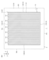
- the semiconductor device 1 includes a peripheral region 10 that is set outside the active region 9 in the chip 2.
- the peripheral region 10 is provided in a region between the periphery of the chip 2 and the active region 9 in a planar view.
- the peripheral region 10 extends in a band shape along the active region 9 in a planar view, and is set in a polygonal ring shape (a square ring in this embodiment) that surrounds the active region 9.
- the active surface 11 may be referred to as the "first surface portion,” the outer peripheral surface 12 as the “second surface portion,” the first to fourth connection surfaces 13A to 13D as the “connection surface portion,” and the active plateau 14 as the “active mesa portion.”
- the active surface 11, the outer peripheral surface 12, and the first to fourth connection surfaces 13A to 13D may be considered to be components of the chip 2 (first main surface 3).
- the active surface 11 is formed in the active region 9. That is, the active surface 11 is formed at a distance inward from the periphery (first to fourth side surfaces 5A to 5D) of the first main surface 3.
- the active surface 11 has a flat surface extending in the first direction X and the second direction Y.
- the active surface 11 is formed by a c-plane (Si-plane).
- the active surface 11 is formed in a quadrangle shape having four sides parallel to the first to fourth side surfaces 5A to 5D in a plan view.
- the outer peripheral surface 12 is formed in the outer peripheral region 10. That is, the outer peripheral surface 12 is formed outside the active surface 11.
- the outer peripheral surface 12 is recessed in the thickness direction of the chip 2 (towards the second main surface 4) relative to the active surface 11. Specifically, in this embodiment, the outer peripheral surface 12 is recessed to a depth less than the thickness of the semiconductor layer 7 so as to expose the semiconductor layer 7. That is, the outer peripheral surface 12 faces the base layer 6 with a portion of the semiconductor layer 7 in between, exposing the semiconductor layer 7.
- the outer peripheral surface 12 extends in a band shape along the active surface 11 in a plan view, and is formed in a ring shape (specifically, a square ring shape) surrounding the active surface 11.
- the outer peripheral surface 12 has a flat surface extending in the first direction X and the second direction Y, and is formed approximately parallel to the active surface 11.
- the outer peripheral surface 12 is formed by a c-plane (Si-plane).
- the outer peripheral surface 12 is connected to the first to fourth side surfaces 5A to 5D.
- the outer peripheral surface 12 has an outer peripheral depth DO.
- the outer peripheral depth DO may be 0.1 ⁇ m or more and 2 ⁇ m or less.
- the outer peripheral depth DO may have a value that falls within any one of the following ranges: 0.1 ⁇ m or more and 0.25 ⁇ m or less, 0.25 ⁇ m or more and 0.5 ⁇ m or less, 0.5 ⁇ m or more and 0.75 ⁇ m or less, 0.75 ⁇ m or more and 1 ⁇ m or less, 1 ⁇ m or more and 1.5 ⁇ m or less, and 1.5 ⁇ m or more and 2 ⁇ m or less.
- the outer peripheral depth DO is preferably 0.1 ⁇ m or more and 1.5 ⁇ m or less.
- the first to fourth connection surfaces 13A to 13D extend in the vertical direction Z and connect the active surface 11 and the outer peripheral surface 12.
- the first connection surface 13A is located on the first side surface 5A side
- the second connection surface 13B is located on the second side surface 5B side
- the third connection surface 13C is located on the third side surface 5C side
- the fourth connection surface 13D is located on the fourth side surface 5D side.
- the first connection surface 13A and the third connection surface 13C extend in the first direction X and face the second direction Y.
- the second connection surface 13B and the fourth connection surface 13D extend in the second direction Y and face the first direction X.
- the first to fourth connection surfaces 13A to 13D may extend approximately vertically between the active surface 11 and the outer peripheral surface 12 so as to define a quadrangular prism-shaped active plateau 14.
- the first to fourth connection surfaces 13A to 13D may be inclined obliquely downward from the active surface 11 toward the outer peripheral surface 12 so as to define a quadrangular pyramid-shaped active plateau 14.
- the active plateau 14 is defined in a protruding shape on the semiconductor layer 7 at the first main surface 3.
- the active plateau 14 is formed only on the semiconductor layer 7, and is not formed on the base layer 6.
- the body region 15 may have a peak p-type impurity concentration of 1 ⁇ 10 15 cm ⁇ 3 or more and 1 ⁇ 10 18 cm ⁇ 3 or less.
- the p-type impurity concentration of the body region 15 is preferably adjusted by at least one trivalent element.
- the trivalent element of the body region 15 may be at least one of boron, aluminum, gallium, and indium.
- the semiconductor device 1 includes a plurality of trench electrode type trench structures 16 formed on the first main surface 3 (active surface 11) in the active region 9.
- the trench structures 16 may be referred to as "gate structures", “trench gate structures”, etc.
- a gate potential is applied to the plurality of trench structures 16 as a control potential.
- the plurality of trench structures 16 control the inversion and non-inversion of the channel (current path) in the body region 15 in response to the gate potential.
- the multiple trench structures 16 are arranged at intervals inward from the periphery (first to fourth connection surfaces 13A to 13D) of the active surface 11 in the active region 9.
- the multiple trench structures 16 are arranged at intervals in the first direction X, and are each formed in a strip shape extending in the second direction Y.
- the multiple trench structures 16 are arranged at intervals in the m-axis direction and each extends in the a-axis direction.
- the multiple trench structures 16 are arranged in stripes extending in the a-axis direction (second direction Y).
- the extension direction of the multiple trench structures 16 coincides with the off-direction Do of the semiconductor layer 7.
- the multiple trench structures 16 are formed at intervals from the lower end (base layer 6) of the semiconductor layer 7 toward the first main surface 3 (active surface 11), and face the base layer 6 with a portion of the semiconductor layer 7 in between.
- the multiple trench structures 16 define a lower region 7a in the region between the bottom walls of the multiple trench structures 16 and the lower end (base layer 6) of the semiconductor layer 7.
- Each trench structure 16 has a trench width WT in the arrangement direction and a trench depth DT in the vertical direction Z.
- the trench width WT is preferably less than the second thickness T2 of the semiconductor layer 7.
- the trench width WT may be 0.1 ⁇ m or more and 5 ⁇ m or less.
- the trench width WT may have a value falling within any one of the following ranges: 0.1 ⁇ m to 0.25 ⁇ m, 0.25 ⁇ m to 0.5 ⁇ m, 0.5 ⁇ m to 0.75 ⁇ m, 0.75 ⁇ m to 1 ⁇ m, 1 ⁇ m to 1.5 ⁇ m, 1.5 ⁇ m to 2 ⁇ m, 2 ⁇ m to 2.5 ⁇ m, 2.5 ⁇ m to 3 ⁇ m, 3 ⁇ m to 3.5 ⁇ m, 3.5 ⁇ m to 4 ⁇ m, 4 ⁇ m to 4.5 ⁇ m, and 4.5 ⁇ m to 5 ⁇ m.
- the trench depth DT is preferably less than the second thickness T2 of the semiconductor layer 7. It is particularly preferable that the trench depth DT is approximately equal to the aforementioned outer periphery depth DO. Of course, the trench depth DT may be greater than or less than the outer periphery depth DO.
- the trench depth DT is preferably greater than the trench width WT.
- each of the multiple trench structures 16 has an aspect ratio DT/WT that extends in a vertically elongated columnar shape.
- the aspect ratio DT/WT is the ratio of the trench width WT to the trench depth DT.
- the trench depth DT may be 0.1 ⁇ m or more and 5 ⁇ m or less.
- the trench depth DT may have a value in any one of the following ranges: 0.1 ⁇ m to 0.25 ⁇ m, 0.25 ⁇ m to 0.5 ⁇ m, 0.5 ⁇ m to 1 ⁇ m, 1 ⁇ m to 1.5 ⁇ m, 1.5 ⁇ m to 2 ⁇ m, 2 ⁇ m to 3 ⁇ m, 3 ⁇ m to 4 ⁇ m, and 4 ⁇ m to 5 ⁇ m.
- the trench depth DT is preferably 0.1 ⁇ m to 1.5 ⁇ m, and more preferably 0.5 ⁇ m to 1.5 ⁇ m.
- the multiple trench structures 16 are arranged in the first direction X at intervals of the trench pitch PT.
- the trench pitch PT is preferably less than the second thickness T2 of the semiconductor layer 7.
- the trench pitch PT is preferably less than the trench depth DT.
- the trench pitch PT may be 0.1 ⁇ m or more and 5 ⁇ m or less.
- the trench pitch PT may have a value in any one of the ranges of 0.1 ⁇ m to 0.25 ⁇ m, 0.25 ⁇ m to 0.5 ⁇ m, 0.5 ⁇ m to 0.75 ⁇ m, 0.75 ⁇ m to 1 ⁇ m, 1 ⁇ m to 1.5 ⁇ m, 1.5 ⁇ m to 2 ⁇ m, 2 ⁇ m to 2.5 ⁇ m, 2.5 ⁇ m to 3 ⁇ m, 3 ⁇ m to 3.5 ⁇ m, 3.5 ⁇ m to 4 ⁇ m, 4 ⁇ m to 4.5 ⁇ m, and 4.5 ⁇ m to 5 ⁇ m.
- the trench pitch PT is preferably 0.5 ⁇ m to 3 ⁇ m, and more preferably 0.5 ⁇ m to 1.5 ⁇ m.
- Each trench structure 16 includes a trench 17, an insulating film 18, and a buried electrode 19.
- the trench 17 is formed in the active surface 11 and defines the walls (side walls and bottom wall) of the trench structure 16.
- the bottom wall of the trench 17 preferably has a flat portion.
- a mesa portion 20 formed by a part of the semiconductor layer 7 is formed between adjacent trenches 17.
- the mesa portion 20 may be referred to as an "element mesa portion.”
- the multiple trenches 17 and multiple mesa portions 20 are in the form of stripes extending along the second direction Y, and are arranged alternately in the first direction X.
- the multiple trenches 17 and multiple mesa portions 20 are arranged in a stripe pattern as a whole.
- the flat portion of the bottom wall of trench 17 extends approximately parallel to first main surface 3.
- the bottom wall of trench 17 has an off angle ⁇ o that is inclined at a predetermined angle in a predetermined off direction Do relative to the c-plane.
- the bottom wall of trench 17 has a flat portion that extends in the off direction Do.
- the bottom wall of trench 17 may be curved in an arc shape toward the lower end side of semiconductor layer 7.
- the insulating film 18 covers the wall surface of the trench 17.
- the insulating film 18 may include at least one of a silicon oxide film, a silicon nitride film, and a silicon oxynitride film.
- the insulating film 18 has a single-layer structure made of a silicon oxide film. It is particularly preferable that the insulating film 18 includes a silicon oxide film made of an oxide of the chip 2.
- the buried electrode 19 is buried in the trench 17 and faces the channel across the insulating film 18. In this embodiment, the buried electrode 19 faces the body region 15 across the insulating film 18.
- the buried electrode 19 may include p-type or n-type conductive polysilicon.
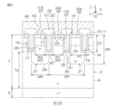
- the semiconductor device 1 includes a plurality of p-type electric field relaxation structures 21 formed at intervals in the horizontal direction in the semiconductor layer 7. Specifically, the plurality of electric field relaxation structures 21 are formed in the mesa portion 20 and the lower region 7a in the semiconductor layer 7. The plurality of electric field relaxation structures 21 are formed in the thickness range between the lower end of the semiconductor layer 7 and the bottom walls of the plurality of trench structures 16.
- the electric field relaxation structures 21 are arranged at intervals in the first direction X in the lower region 7a, and are each formed in a strip shape extending in the second direction Y. In other words, the electric field relaxation structures 21 are arranged at intervals in the m-axis direction and extend in the a-axis direction of the SiC single crystal. The electric field relaxation structures 21 are formed in stripes extending in the a-axis direction (second direction Y), and the extension direction of the electric field relaxation structures 21 coincides with the off-direction Do of the semiconductor layer 7.
- the electric field relaxation structures 21 are arranged at intervals of the relaxation pitch PR in the first direction X. It is preferable that the relaxation pitch PR is at least twice the trench pitch PT.
- the relaxation pitch PR may have a value in any one of the following ranges: 0.25 ⁇ m to 0.5 ⁇ m, 0.5 ⁇ m to 0.75 ⁇ m, 0.75 ⁇ m to 1 ⁇ m, 1 ⁇ m to 1.5 ⁇ m, 1.5 ⁇ m to 2 ⁇ m, 2 ⁇ m to 2.5 ⁇ m, 2.5 ⁇ m to 3 ⁇ m, 3 ⁇ m to 3.5 ⁇ m, 3.5 ⁇ m to 4 ⁇ m, 4 ⁇ m to 4.5 ⁇ m, and 4.5 ⁇ m to 5 ⁇ m.
- the relaxation pitch PR is preferably 2.5 ⁇ m to 3 ⁇ m.
- the trench pitch PT is preferably 0.5 ⁇ m to 1.5 ⁇ m.
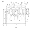
- Each electric field relaxation structure 21 is formed integrally with the body region 15 and spans the bottom walls of multiple trenches 17.
- each electric field relaxation structure 21 extends from the body region 15 sandwiched between two adjacent trenches 17 downward in the vertical direction Z below the bottom walls of the trenches 17, and spreads in the horizontal direction along the first main surface 3, overlapping the bottom walls of the trenches 17 on both sides.
- Each electric field relaxation structure 21 covers the bottom wall of the trench 17.
- each electric field relaxation structure 21 forms at least a part of each of the side walls and bottom walls of the trench 17, and is in contact with the insulating film 18.
- Each electric field relaxation structure 21 has a substantially L-shaped exposed surface that is exposed within each trench 17 as the lower part of the side wall of the trench 17 and the bottom wall of the trench 17 that is continuous with the lower part of the side wall.
- the body region 15 includes a channel portion 22 and a non-channel portion 23.
- the channel portion 22 is physically and electrically isolated from the electric field relaxation structure 21.
- a channel is formed along the wall surface of the trench 17 adjacent to the channel portion 22.
- the non-channel portion 23 is physically and electrically integrated with the electric field relaxation structure 21.
- the non-channel portion 23 has a bottom wall covered from below by the electric field relaxation structure 21.
- the channel portions 22 and non-channel portions 23 may be arranged alternately in the first direction X as shown in Figures 7 to 9, or multiple channel portions 22 may be interposed between adjacent non-channel portions 23.
- multiple electric field relaxation structures 21 may be alternately connected to multiple mesa portions 20 arranged in the first direction X with trenches 17 between them, or multiple mesa portions 20 to which no electric field relaxation structure 21 is connected may be interposed between mesa portions 20 to which an electric field relaxation structure 21 is connected.
- the channel portion 22 and the non-channel portion 23 have the same width in the first direction X.
- the first width W1 of the mesa portion 20 that forms the channel portion 22 and the second width W2 of the mesa portion 20 that forms the non-channel portion 23 may be the same.
- the first width W1 second width W2 is obtained by arranging multiple trenches 17 at equal intervals (trench pitch PT) in the first direction X.
- the electric field relaxation structure 21 forms a boundary portion 24 with the bottom of the non-channel portion 23 between adjacent trenches 17.
- the boundary portion 24 is formed in a linear shape in cross section that divides the mesa portion 20 horizontally from the sidewall of the trench 17 on one side to the sidewall of the trench 17 on the other side.
- the boundary portion 24 divides the mesa portion 20 into the body region 15 (non-channel portion 23) on the first main surface 3 side and the electric field relaxation structure 21 on the second main surface 4 side.
- the boundary portion 24 does not need to be clearly defined by image analysis (e.g., SEM image analysis, etc.) because both the body region 15 (non-channel portion 23) and the electric field relaxation structure 21 are p-type.
- image analysis e.g., SEM image analysis, etc.
- the fact that the body region 15 and the electric field relaxation structure 21 are continuous in the vertical direction Z may be confirmed, for example, by obtaining a profile of the p-type impurity concentration in the vertical direction Z from the first main surface 3 to the second main surface 4.
- the body region 15 corresponding to the channel portion 22 may be referred to as a "first body region 25 of the second conductivity type," and the integral body region 15 corresponding to the non-channel portion 23 and the electric field relaxation structure 21 may be referred to as a "second body region 26 of the second conductivity type.”
- the first body regions 25 and the second body regions 26 may be alternately arranged in the first direction X as shown in FIG. 8, or multiple first body regions 25 may be interposed between adjacent second body regions 26.
- the first body region 25 is formed only in the mesa portion 20 between adjacent trenches 17, and has a bottom on the first main surface 3 side of the bottom wall of the trench 17.
- the second body region 26 has the mesa portion 20 between adjacent trenches 17 and a protrusion 27 that protrudes from the mesa portion 20 toward the second main surface 4 side of the bottom wall of the trench 17.
- the protrusion 27 of the second body region 26 spreads in the horizontal direction along the first main surface 3, overlaps with the bottom walls of the trenches 17 on both sides, and covers the bottom walls of the trenches 17 from below.
- each electric field relaxation structure 21 may integrally have a base portion 28 on the second main surface 4 side of the bottom walls of two adjacent trenches 17, and a protrusion portion 29 sandwiched between two adjacent trenches 17.
- the base portion 28 overlaps two adjacent trenches 17 and crosses the area between the two trenches 17 in the first direction X.
- the base portion 28 has a width greater than the trench pitch PT.
- the base portion 28 has an end that protrudes horizontally outward beyond the area directly below the mesa portion 20.
- the protrusion 29 extends from the base portion 28 along the sidewall of each trench 17 to the inside of the mesa portion 20 and is connected to the bottom of the body region 15.
- the protrusion 29 is formed over the entire mesa portion 20, from the bottom wall of the trench 17 in the vertical direction Z to the body region 15.
- each electric field relaxation structure 21 may have an end 30 at a central position of the bottom wall on the non-channel portion 23 side relative to the wall surface (sidewall) of the trench 17 on the channel portion 22 side in the width direction of the trench 17.
- the bottom wall of the trench 17 may have a first portion 31 formed on the non-channel portion 23 side in the width direction of the trench 17 and covered by the electric field relaxation structure 21.
- the bottom wall of the trench 17 may also have a second portion 32 formed on the channel portion 22 side relative to the first portion 31 and covered by the semiconductor layer 7 (drift region 8).
- each electric field relaxation structure 21 may be planar and parallel or approximately parallel to the first main surface 3 in the first direction X and the second direction Y. Therefore, in this embodiment, the portion of each electric field relaxation structure 21 closer to the second main surface 4 than the bottom wall of the trench 17 (the protruding portion 27 of the second body region 26) is formed in an approximately rectangular shape in cross section.
- the p-type impurity concentration of the electric field relaxation structure 21 is preferably higher than the p-type impurity concentration of the body region 15.
- the electric field relaxation structure 21 may have a peak p-type impurity concentration of 1 ⁇ 10 16 cm ⁇ 3 or more and 1 ⁇ 10 19 cm ⁇ 3 or less.
- the p-type impurity concentration of the electric field relaxation structure 21 may be approximately constant in the thickness direction.
- the p-type impurity concentration of the electric field relaxation structure 21 may have a concentration gradient that gradually increases and/or gradually decreases in the stacking direction (crystal growth direction).
- the electric field relaxation structure 21 has a relaxation depth DR in the vertical direction Z that is greater than that of the trench 17. More preferably, the relaxation depth DR of the electric field relaxation structure 21 is at least twice the trench depth DT. Of course, the relaxation depth DR may be less than twice the trench depth DT.
- the relaxation depth DR may have a value in any one of the following ranges: greater than 0.25 ⁇ m and equal to or less than 0.5 ⁇ m, equal to or greater than 0.5 ⁇ m and equal to or less than 1 ⁇ m, equal to or greater than 1.5 ⁇ m, equal to or greater than 1.5 ⁇ m and equal to or less than 2 ⁇ m, equal to or greater than 2 ⁇ m and equal to or less than 3 ⁇ m, equal to or greater than 3 ⁇ m and equal to or less than 4 ⁇ m, and equal to or greater than 4 ⁇ m and equal to or less than 5 ⁇ m.
- the relaxation depth DR is preferably equal to or greater than 2 ⁇ m and equal to or less than 3 ⁇ m, in which case the trench depth DT is preferably equal to or greater than 0.5 ⁇ m and equal to or less than 1.5 ⁇ m.
- Each of the multiple electric field relaxation structures 21 has a relaxation width WR in the arrangement direction. It is preferable that the relaxation width WR is at least wider than the second width W2 (the width of the mesa portion 20 of the non-channel portion 23). Of course, the relaxation width WR may be the same width as the second width W2.
- the relaxation width WR may be 0.25 ⁇ m or more and 5 ⁇ m or less.
- the relaxation width WR may have a value that falls within any one of the following ranges: 0.25 ⁇ m or more and 0.5 ⁇ m or less, 0.5 ⁇ m or more and 0.75 ⁇ m or less, 0.75 ⁇ m or more and 1 ⁇ m or less, 1 ⁇ m or more and 1.5 ⁇ m or less, 1.5 ⁇ m or more and 2 ⁇ m or less, 2 ⁇ m or more and 2.5 ⁇ m or less, 2.5 ⁇ m or more and 3 ⁇ m or less, 3 ⁇ m or more and 3.5 ⁇ m or less, 3.5 ⁇ m or more and 4 ⁇ m or less, 4 ⁇ m or more and 4.5 ⁇ m or less, and 4.5 ⁇ m or more and 5 ⁇ m or less.
- the semiconductor device 1 includes a plurality of source regions 33 formed on one side of a plurality of trench structures 16 in the surface layer portion of the first main surface 3 (active surface 11).
- the plurality of source regions 33 which are an example of a third impurity region, are formed in the surface layer portion of the body region 15.
- the plurality of source regions 33 are selectively formed in the channel portion 22 of the plurality of body regions 15 including the channel portion 22 and the non-channel portion 23.
- the plurality of source regions 33 have a higher n-type impurity concentration (peak value) than that of the semiconductor layer 7.
- the plurality of source regions 33 may have an n-type impurity concentration (peak value) of not less than 1 ⁇ 10 18 cm ⁇ 3 and not more than 1 ⁇ 10 21 cm ⁇ 3 .
- the multiple source regions 33 extend in a band shape in the extension direction of the corresponding trench structure 16 in a plan view.
- the multiple source regions 33 are formed at intervals from the bottom of the body region 15 toward the active surface 11, and face the drift region 8 directly below, sandwiching a part of the body region 15 in the vertical direction Z.
- the semiconductor device 1 includes a plurality of contact regions 34 formed in the surface portion of the first main surface 3 (active surface 11) in the region between the plurality of trench structures 16.
- the plurality of contact regions 34 are formed in the surface portion of the body region 15.
- the multiple contact regions 34 have a p-type impurity concentration (peak value) higher than the p-type impurity concentration (peak value) of the body region 15.
- the p-type impurity concentration (peak value) of the multiple contact regions 34 is higher than the p-type impurity concentration (peak value) of the multiple electric field relaxation structures 21.
- the multiple contact regions 34 may have a p-type impurity concentration (peak value) of 1 ⁇ 10 18 cm ⁇ 3 or more and 1 ⁇ 10 21 cm ⁇ 3 or less.
- the multiple contact regions 34 include a first contact region 35 and a second contact region 36.
- the first contact region 35 is formed in the non-channel portion 23, and the second contact region 36 is formed in the channel portion 22.
- the first contact region 35 is formed over the entire first main surface 3 between the trench structure 16 on one side of the non-channel portion 23 and the trench structure 16 on the other side.
- the first contact region 35 extends in a band shape in the extension direction of the multiple trench structures 16.
- the first contact region 35 crosses the mesa portion 20 of the non-channel portion 23 from the trench structure 16 on one side of the non-channel portion 23 to the trench structure 16 on the other side.
- the first contact region 35 is exposed on the wall surfaces (sidewalls) of the trench 17 on both sides of the non-channel portion 23 in the first direction X, and is in contact with the insulating film 18.
- the first contact region 35 is formed at a distance from the bottom of the body region 15 toward the active surface 11, and faces the drift region 8 directly below in the vertical direction Z, sandwiching the body region 15 and a part of the electric field relaxation structure 21 therebetween.
- the second contact region 36 is interposed in the region between the adjacent source regions 33 in the channel portion 22, and extends in a band shape in the extension direction of the trench structures 16.
- the second contact region 36 is formed at a distance from the bottom of the body region 15 toward the active surface 11, and faces the drift region 8 directly below, sandwiching a part of the body region 15 in the vertical direction Z.
- the source region 33 is selectively formed in the channel portion 22 out of the channel portion 22 and the non-channel portion 23.
- the source region 33 is not formed in the non-channel portion 23, and the first contact region 35 is formed over the entire surface portion of the body region 15. This makes it possible to separate the function of the channel portion 22 that forms a current path from the function of the non-channel portion 23 that ensures electrical contact with the body region 15. As a result, an efficient ON operation can be achieved.
- the lower portion of the body region 15 is completely covered by the electric field relaxation structure 21, so it is not very effective as a channel. Therefore, in the non-channel portion 23, the first contact region 35 is formed over the entire surface portion of the body region 15, thereby stabilizing the potential of the body region 15.
- Figure 10 is a perspective view showing the configuration of the outer peripheral region 10.
- Figure 11 is a cross-sectional view showing a main part of the outer peripheral region 10.
- the semiconductor device 1 includes a p-type well region 37 formed in a surface layer portion of the outer peripheral surface 12.
- the well region 37 is formed at a distance from the periphery of the outer peripheral surface 12 (first to fourth side surfaces 5A to 5D) toward the active surface 11 in a plan view, and extends in a band shape along the active surface 11.
- the well region 37 is formed in a ring shape (specifically, a square ring shape) surrounding the active surface 11 in a plan view.
- the well region 37 is pulled out from the surface portion of the outer peripheral surface 12 toward the first to fourth connection surfaces 13A to 13D and extends along the surface portions of the first to fourth connection surfaces 13A to 13D.
- the well region 37 is electrically connected to the body region 15 at the surface portion of the active surface 11.
- the well region 37 is formed at a distance from the lower end of the semiconductor layer 7 towards the outer circumferential surface 12, and faces the base layer 6 with a part of the semiconductor layer 7 in between.
- the well region 37 forms a pn junction with the semiconductor layer 7.
- the well region 37 may have a peak p-type impurity concentration of 1 ⁇ 10 15 cm -3 or more and 1 ⁇ 10 18 cm -3 or less.
- the well region 37 has a p-type impurity concentration lower than the p-type impurity concentration of the contact region 34.
- the p-type impurity concentration of the well region 37 may be higher than the p-type impurity concentration of the body region 15. Of course, the p-type impurity concentration of the well region 37 may be lower than the body region 15. It is preferable that the p-type impurity concentration of the well region 37 is adjusted by at least one kind of trivalent element.
- the trivalent element of the well region 37 may be the same kind as the trivalent element of the electric field relaxation structure 21, or may be a different kind from the trivalent element of the electric field relaxation structure 21.
- the trivalent element of the well region 37 may be at least one kind of boron, aluminum, gallium, and indium.
- the semiconductor device 1 includes at least one (preferably 2 to 20) p-type field region 38 formed in the surface layer of the outer peripheral surface 12 (first main surface 3) in the outer peripheral region 10.
- the number of the multiple field regions 38 is typically 4 to 8.
- the multiple field regions 38 are formed in an electrically floating state, and relieve the electric field within the chip 2 at the periphery of the first main surface 3.
- the number, width, depth, p-type impurity concentration, etc. of the field regions 38 are arbitrary and can take various values depending on the electric field to be relieved.
- the multiple field regions 38 are arranged at intervals from the periphery of the active surface 11 (first to fourth connection surfaces 13A to 13D) and the periphery of the chip 2 (first to fourth side surfaces 5A to 5D). Specifically, the multiple field regions 38 are arranged at intervals from the well region 37 to the periphery side of the outer circumferential surface 12.
- the multiple field regions 38 are formed in a band shape extending along the active region 9 in a planar view.
- the multiple field regions 38 each have a portion extending in a band shape in the first direction X and a portion extending in a band shape in the second direction Y.
- the multiple field regions 38 are formed in a ring shape (specifically, a square ring shape) surrounding the active region 9 (i.e., the multiple electric field relaxation structures 21) in a planar view.
- the multiple field regions 38 are formed in the semiconductor layer 7 at intervals from the lower end of the semiconductor layer 7 toward the outer circumferential surface 12, and form a pn junction with the semiconductor layer 7. It is preferable that the multiple field regions 38 have a bottom portion located on the outer circumferential surface 12 side relative to the intermediate portion of the thickness range of the semiconductor layer 7.
- the multiple field regions 38 are formed at intervals from the multiple electric field relaxation structures 21 toward the peripheral edge of the chip 2. Therefore, the multiple field regions 38 do not face the multiple electric field relaxation structures 21 in the vertical direction Z.
- the multiple field regions 38 are located closer to the second main surface 4 of the semiconductor layer 7 than the bottom wall of the trench structure 16.
- the bottoms of the multiple field regions 38 may be located closer to the first main surface 3 of the semiconductor layer 7 than the depth positions of the bottoms of the multiple electric field relaxation structures 21.
- the bottoms of the multiple field regions 38 may be located closer to the second main surface 4 of the semiconductor layer 7 than the depth positions of the bottoms of the multiple electric field relaxation structures 21.
- the plurality of field regions 38 may have a peak p-type impurity concentration of 1 ⁇ 10 15 cm ⁇ 3 or more and 1 ⁇ 10 18 cm ⁇ 3 or less.
- the p-type impurity concentration of the field region 38 may be approximately equal to the p-type impurity concentration of the body region 15.
- the p-type impurity concentration of the plurality of field regions 38 may be higher than the p-type impurity concentration of the body region 15.
- the p-type impurity concentration of the plurality of field regions 38 may be lower than the p-type impurity concentration of the body region 15.
- the p-type impurity concentration of the multiple field regions 38 is preferably adjusted by at least one type of trivalent element.
- the trivalent element of the field region 38 may be the same type as the trivalent element of the electric field relaxation structure 21, or may be a different type from the trivalent element of the electric field relaxation structure 21.
- the trivalent element of the field region 38 may be at least one type of boron, aluminum, gallium, and indium.
- the multiple field regions 38 are preferably formed at a pitch different from the relaxation pitch PR of the electric field relaxation structure 21. It is particularly preferable that the pitch of the multiple field regions 38 is smaller than the relaxation pitch PR. The pitch of the multiple field regions 38 may be larger than the relaxation pitch PR. The pitch of the multiple field regions 38 may be approximately equal to the relaxation pitch PR.
- the semiconductor device 1 includes an interlayer insulating film 39 covering the first main surface 3.
- the interlayer insulating film 39 may be referred to as an "insulating film,” an "interlayer film,” an “intermediate insulating film,” or the like.
- the interlayer insulating film 39 has a layered structure including a first insulating film 40 and a second insulating film 41.
- the first insulating film 40 may include at least one of a silicon oxide film, a silicon nitride film, and a silicon oxynitride film. It is particularly preferable that the first insulating film 40 includes a silicon oxide film made of an oxide of the chip 2 (semiconductor layer 7).
- the first insulating film 40 selectively covers the first main surface 3 in the active region 9 and the peripheral region 10. Specifically, the first insulating film 40 selectively covers the active surface 11, the peripheral surface 12, and the first to fourth connection surfaces 13A to 13D. The first insulating film 40 is connected to the insulating film 18 in the active surface 11, exposing the buried electrode 19.
- the first insulating film 40 covers the well region 37 and the multiple field regions 38 on the outer peripheral surface 12.
- the first insulating film 40 is continuous with the first to fourth side surfaces 5A to 5D.
- the first insulating film 40 may be formed at a distance inward from the periphery of the outer peripheral surface 12, exposing the semiconductor layer 7 from the periphery of the outer peripheral surface 12.
- the first insulating film 40 covers the body region 15 and well region 37 on the first to fourth connection surfaces 13A to 13D.
- the second insulating film 41 is laminated on the first insulating film 40.
- the second insulating film 41 may include at least one of a silicon oxide film, a silicon nitride film, and a silicon oxynitride film.
- the interlayer insulating film 39 preferably includes a silicon oxide film.
- the second insulating film 41 covers the first main surface 3 in the active region 9 and the peripheral region 10, sandwiching the first insulating film 40 between them. Specifically, the second insulating film 41 selectively covers the active surface 11, the peripheral surface 12, and the first to fourth connection surfaces 13A to 13D, sandwiching the first insulating film 40 between them.
- the second insulating film 41 covers the multiple trench structures 16 (buried electrodes 19) in the active region 9.
- the second insulating film 41 covers the well region 37 and multiple field regions 38 in the peripheral region 10, sandwiching the first insulating film 40 between them.
- the second insulating film 41 is continuous with the first to fourth side surfaces 5A to 5D.
- the second insulating film 41 may be formed at a distance inward from the periphery of the peripheral surface 12, exposing the periphery of the first main surface 3 together with the first insulating film 40.
- the semiconductor device 1 includes a plurality of contact openings 42 formed in the interlayer insulating film 39.
- the plurality of contact openings 42 include a plurality of contact openings 42 (not shown) that expose a plurality of trench structures 16 (buried electrodes 19), and a plurality of contact openings 42 that expose a plurality of source regions 33.
- the plurality of contact openings 42 for the source regions 33 are formed in the regions between the plurality of adjacent trench structures 16, and expose the plurality of source regions 33 and the plurality of contact regions 34.
- the semiconductor device 1 includes a sidewall structure 43 disposed in the interlayer insulating film 39 so as to cover at least one of the first to fourth connection surfaces 13A to 13D.
- the sidewall structure 43 is disposed on the first insulating film 40 and is covered by the second insulating film 41.
- the sidewall structure 43 reduces the step formed between the active surface 11 and the outer peripheral surface 12.
- the sidewall structure 43 is formed in a band shape extending along at least one of the first to fourth connection surfaces 13A to 13D.
- the sidewall structure 43 is formed in a ring shape (specifically, a square ring shape) extending along the first to fourth connection surfaces 13A to 13D so as to surround the active surface 11 in a plan view.
- the sidewall structure 43 may have a portion that extends in a film shape along the outer peripheral surface 12, and a portion that extends in a film shape along the first to fourth connection surfaces 13A to 13D.
- the sidewall structure 43 is formed at a distance from the innermost field region 38 toward the active surface 11, and faces the well region 37 in the horizontal and vertical directions Z, sandwiching the first insulating film 40 therebetween.
- the sidewall structure 43 may face the body region 15, sandwiching the first insulating film 40 therebetween.
- the semiconductor device 1 includes a gate pad 44 disposed on the interlayer insulating film 39.
- the gate pad 44 is an electrode to which a gate potential is applied from the outside.
- the gate pad 44 may be referred to as a "gate pad electrode", a "first pad electrode”, etc.
- the gate pad 44 may have a layered structure including a Ti-based metal film and an Al-based metal film layered in this order from the interlayer insulating film 39 side.
- the gate pad 44 is disposed on a portion of the interlayer insulating film 39 that covers the active region 9. Specifically, the gate pad 44 is disposed on the active surface 11 at a distance from the outer peripheral surface 12 in a plan view. The gate pad 44 is disposed in a region close to the center of one side of the active surface 11 (the second connection surface 13B in this embodiment) in a plan view.
- the gate pad 44 may be disposed in a region along any of the central portions of the first to fourth connection surfaces 13A to 13D.
- the gate pad 44 may be disposed at any corner of the active surface 11 in a planar view.
- the gate pad 44 may also be disposed at the central portion of the active surface 11 in a planar view.
- the gate pad 44 is formed in a quadrangular shape in a planar view.
- the semiconductor device 1 includes at least one gate wiring 45 (multiple in this embodiment) that is drawn from the gate pad 44 onto the interlayer insulating film 39.
- the gate wiring 45 may also be referred to as a "wiring", a “wiring electrode”, etc.
- the multiple gate wirings 45 are arranged on the active surface 11 at a distance from the outer peripheral surface 12 in a plan view.
- the multiple gate wirings 45 may have a laminated structure including a Ti-based metal film and an Al-based metal film laminated in this order from the interlayer insulating film 39 side.
- the multiple gate wirings 45 include a first gate wiring 45A and a second gate wiring 45B.
- the first gate wiring 45A is pulled out from the gate pad 44 toward the first connection surface 13A and extends in a line along the periphery of the active surface 11 so as to intersect (specifically, perpendicularly) with a portion (specifically, one end) of the multiple trench structures 16.
- the first gate wiring 45A penetrates the interlayer insulating film 39 via the multiple contact openings 42 and is electrically connected to one end of the multiple trench structures 16.
- the second gate wiring 45B is pulled out from the gate pad 44 toward the third connection surface 13C and extends in a line along the periphery of the active surface 11 so as to intersect (specifically, perpendicular to) a portion (specifically, the other end) of the multiple trench structures 16.
- the second gate wiring 45B penetrates the interlayer insulating film 39 via the multiple contact openings 42 and is electrically connected to the other end of the multiple trench structures 16.
- the semiconductor device 1 includes a source pad 46 disposed on the interlayer insulating film 39 at a distance from the gate pad 44 and the gate wiring 45.
- the source pad 46 is an electrode to which a source potential is applied from the outside.
- the source pad 46 may be referred to as a "source pad electrode", a "second pad electrode”, etc.
- the source pad 46 may have a layered structure including a Ti-based metal film and an Al-based metal film layered in this order from the interlayer insulating film 39 side.
- the source pad 46 is disposed on the active surface 11 at a distance from the outer peripheral surface 12 in a plan view.
- the source pad 46 is formed in a polygonal shape having a recess along the gate pad 44 in a plan view.
- the source pad 46 may also be formed in a square shape in a plan view.
- the source pad 46 penetrates the interlayer insulating film 39 through a plurality of contact openings 42, and is electrically connected to the body region 15, the plurality of source regions 33, and the plurality of contact regions 34. In other words, the source pad 46 is electrically connected to the plurality of electric field relaxation structures 21 through the body region 15.
- the semiconductor device 1 includes a drain pad 47 covering the second main surface 4.
- the drain pad 47 is an electrode to which a drain potential is applied from the outside.
- the drain pad 47 may be referred to as a "drain pad electrode”, a “third pad electrode”, etc.
- the drain pad 47 forms an ohmic contact with the base layer 6 exposed from the second main surface 4.
- the drain pad 47 is electrically connected to the multiple drift regions 8 via the base layer 6.
- the drain pad 47 may cover the entire second main surface 4 so as to be continuous with the periphery of the chip 2 (first to fourth side surfaces 5A to 5D).
- the drain pad 47 may cover the second main surface 4 at a distance inward from the periphery of the chip 2 so as to expose the periphery of the chip 2.
- the breakdown voltage that can be applied between the source pad 46 and the drain pad 47 (between the first main surface 3 and the second main surface 4) may be 500 V or more and 3000 V or less.
- the breakdown voltage may have a value that belongs to any one of the following ranges: 500 V or more and 1000 V or less, 1000 V or more and 1500 V or less, 1500 V or more and 2000 V or less, 2000 V or more and 2500 V or less, and 2500 V or more and 3000 V or less.
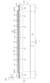
- FIG. 12 is a schematic diagram showing a wafer 50 used in the manufacture of the semiconductor device 1.
- the wafer 50 is a substrate for the base layer 6 and contains SiC single crystal.
- the wafer 50 is formed in a flat disk shape. Of course, the wafer 50 may also be formed in a flat rectangular parallelepiped shape.
- the wafer 50 has a first wafer main surface 51 on one side, a second wafer main surface 52 on the other side, and a wafer side surface 53 connecting the first wafer main surface 51 and the second wafer main surface 52.
- the first wafer main surface 51 corresponds to the upper end of the base layer 6, and the second wafer main surface 52 corresponds to the lower end of the base layer 6.
- the first wafer main surface 51 and the second wafer main surface 52 are formed by the c-plane of the SiC single crystal.
- the first wafer main surface 51 is formed by the silicon surface of the SiC single crystal, and the second wafer main surface 52 is formed by the carbon surface of the SiC single crystal.
- the wafer 50 (the first wafer main surface 51 and the second wafer main surface 52) has the off-direction Do and off-angle ⁇ o described above.
- the wafer 50 has a mark 54 on the wafer side surface 53 that indicates the crystal orientation of the SiC single crystal.
- the mark 54 may include either or both of an orientation flat and an orientation notch.
- the orientation flat consists of a cutout that is cut in a straight line in a plan view.
- the orientation notch consists of a cutout that is cut in a concave shape (e.g., a tapered shape) toward the center of the first wafer main surface 51 in a plan view.
- the mark 54 may include either or both of a first orientation flat extending in the m-axis direction and a second orientation flat extending in the a-axis direction.
- the mark 54 may include either or both of an orientation notch recessed in the m-axis direction and an orientation notch recessed in the a-axis direction.
- FIG. 12 an orientation flat extending in the m-axis direction (first direction X) in a plan view is shown.
- a plurality of device regions 55 and a plurality of cutting lines 56 are set on the wafer 50 by alignment marks or the like.
- Each device region 55 is an area corresponding to a semiconductor device 1.
- Each of the plurality of device regions 55 is set to have a rectangular shape in a plan view.
- the multiple device regions 55 are set in a matrix along the first direction X and the second direction Y in a plan view.
- the multiple device regions 55 are each set at intervals inward from the periphery of the first wafer main surface 51 in a plan view.
- the multiple cutting lines 56 are set in a lattice extending along the first direction X and the second direction Y to partition the multiple device regions 55.
- FIG. 13 is a flowchart showing an example of a method for manufacturing the semiconductor device 1.
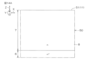
- FIG. 14A to FIG. 14H are cross-sectional views showing an example of a method for manufacturing the semiconductor device 1.
- FIG. 14A to FIG. 14H are cross-sectional views corresponding to FIG. 7.
- the aforementioned wafer 50 preparation process is carried out (step S1 in FIG. 13).
- the semiconductor layer 7 formation process is carried out (step S2 in FIG. 13).
- the semiconductor layer 7 is formed starting from the first wafer main surface 51 (wafer 50) by epitaxial growth.
- step S3 in FIG. 13 the process of forming the body region 15 is carried out.
- p-type impurities are introduced into the entire semiconductor layer 7.
- the body region 15 is formed over the entire surface portion of the semiconductor layer 7.
- a step of forming a first mask 60 having a predetermined pattern is performed (step S4 in FIG. 13).
- the first mask 60 is preferably an inorganic mask (hard mask).
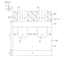
- the first mask 60 is disposed on the upper end of the semiconductor layer 7, and has a plurality of first openings 61 that expose regions in which a plurality of electric field relaxation structures 21 are to be formed.
- a step of forming a plurality of electric field relaxation structures 21 is performed (step S5 in FIG. 13).
- p-type impurities are selectively introduced into the semiconductor layer 7 via the first mask 60. This forms the electric field relaxation structures 21 connected to the lower portion of the body region 15.
- the electric field relaxation structure 21 may be formed by a channeling ion implantation method.
- the channeling implantation process is performed based on data (information) of the off angle ⁇ o. If it is a channeling implantation process, the electric field relaxation structure 21 can be selectively and easily formed at a deep position in the semiconductor layer 7. If the electric field relaxation structure 21 is formed by a channeling ion implantation method, the electric field relaxation structure 21 may be formed before the body region 15.
- the first mask 60 is removed (step S6 in FIG. 13).
- a process for forming a plurality of source regions 33 is carried out (step S7 in FIG. 13).
- the plurality of source regions 33 are formed by introducing n-type impurities into the surface layer of the semiconductor layer 7 by ion implantation through a mask (not shown) having a predetermined layout.
- a process for forming a plurality of contact regions 34 is performed (step S8 in FIG. 13).
- the plurality of contact regions 34 are formed by introducing p-type impurities into the surface layer of the semiconductor layer 7 by ion implantation through a mask (not shown) having a predetermined layout.
- the first contact region 35 and the second contact region 36 are formed physically independent of each other.
- the process for forming the contact regions 34 may be performed prior to the process for forming the source region 33.
- a process for forming a plurality of trenches 17 is performed.
- a second mask (not shown) having a predetermined pattern is formed (step S9 in FIG. 13).
- the second mask is preferably an inorganic mask (hard mask).
- unnecessary portions of the semiconductor layer 7 are removed by an etching method via the second mask.
- the etching method may be either or both of a wet etching method and a dry etching method.
- the etching method is preferably an RIE (Reactive Ion Etching) method.
- RIE Reactive Ion Etching
- a step of forming the insulating film 18 is performed (step S11 in FIG. 13).
- the step of forming the insulating film 18 also serves as a step of forming the first insulating film 40.
- the insulating film 18 may be formed by either one or both of a CVD (Chemical Vapor Deposition) method and an oxidation process method.
- the insulating film 18 and the first insulating film 40 are typically formed by a thermal oxidation process method.
- the insulating film 18 is formed in the form of a film on the wall surfaces of the multiple trenches 17, and the first insulating film 40 is formed in the form of a film in the region of the upper end of the semiconductor layer 7 outside the multiple trenches 17.
- a process for forming the buried electrode 19 is performed (step S12 in FIG. 13).
- This process includes a process for forming a base electrode film on the insulating film 18.
- the base electrode film includes conductive polysilicon.
- the base electrode film backfills the multiple trenches 17 and covers the upper end of the semiconductor layer 7.
- the base electrode film may be formed by a CVD method.
- unnecessary portions of the buried electrode 19 are removed by an etching method.
- the unnecessary portions of the buried electrode 19 are removed until the insulating film 18 is exposed.
- the etching method may be either one or both of a wet etching method and a dry etching method. As a result, multiple buried electrodes 19 are buried in the multiple trenches 17, respectively, and multiple trench structures 16 are formed.
- the interlayer insulating film 39 may be formed by a CVD method.
- a plurality of contact openings 42 having a predetermined layout are formed in the interlayer insulating film 39 by an etching method using a mask (not shown) having a predetermined layout.
- the gate pad 44, gate wiring 45, and source pad 46 are formed by depositing a metal film on the interlayer insulating film 39 by sputtering, and then shaping it into a predetermined layout by etching using a mask (not shown) having a predetermined layout.
- drain pad 47 is formed by depositing a metal film on the second wafer main surface 52 by a sputtering method.
- the wafer 50 is then cut along a number of intended cutting lines 56 (step S16 in FIG. 13).
- the electric field relaxation structure 21 is formed on the bottom wall of the trench 17, so that the electric field concentration on the bottom wall of the trench 17 in the trench gate structure related to the MISFET (Metal Insulator Semiconductor Field Effect Transistor) can be mitigated.
- MISFET Metal Insulator Semiconductor Field Effect Transistor
- the electric field relaxation structure 21 is not formed one-to-one with each trench 17, but spans the bottom walls of multiple trenches 17. In this form, one electric field relaxation structure 21 spans the bottom walls of two adjacent trenches 17. This allows the dimensions of the electric field relaxation structure 21 (e.g., relaxation width WR, relaxation pitch PR, etc.) to be set with an independent design that is not dependent on the width WT of each trench 17 or the pitch PT of multiple trenches 17. As a result, with appropriate design, the electric field relaxation structure 21 can be easily fabricated.
- the electric field relaxation structure 21 e.g., relaxation width WR, relaxation pitch PR, etc.
- a sufficient processing dimension margin can be obtained by using a pattern of the electric field relaxation structure 21 having a width WR wider than the trench pitch PT.
- the trench pitch PT the relaxation pitch PR
- the electric field relaxation structure 21 will be formed horizontally away from the trench 17, and the bottom wall of the trench 17 will not be covered with the electric field relaxation structure 21, which may cause a decrease in breakdown voltage.
- the electric field relaxation structure 21 is formed wide in the horizontal direction, so that the bottom wall of the trench 17 can be reliably covered with the electric field relaxation structure 21.
- the electric field relaxation structure 21 must be formed deeper than the body region 15, so the first mask 60 must be formed relatively thick.
- the ions In order to implant ions deep into the region, the ions must be accelerated with high energy, and this is to prevent the accelerated ions from penetrating the first mask 60 for implantation. Therefore, as the width of the first mask 60 becomes narrower due to miniaturization, the aspect ratio of the first mask 60 tends to become higher. If the aspect ratio is high, the durability of the first mask 60 against external forces decreases, and the first mask 60 is more likely to fall or tilt due to its own weight or external forces.
- the dimensions of the electric field relaxation structure 21 can be designed independently of the dimensions of the trench 17, the aspect ratio of the first mask 60 can be kept low. As a result, the electric field relaxation structure 21 can be formed with high precision even if the trench 17 is miniaturized.
- the portion of the body region 15 that is physically and electrically integrated with the electric field relaxation structure 21 is covered with the second conductivity type portion (body region 15 and electric field relaxation structure 21) from the sidewall to the bottom wall of the trench 17. Since the range in which an inversion layer should be formed along the inner wall of the trench 17 is long, the voltage (threshold voltage) required to form a channel tends to be selectively higher than that of the channel portion 22. Therefore, by making the portion of the body region 15 that is physically and electrically integrated with the electric field relaxation structure 21 into a non-channel portion 23, it is possible to suppress variation in the threshold voltage of the semiconductor device 1.
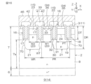
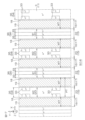
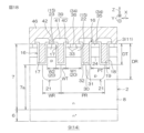
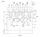
- FIGS. 15 to 20 are diagrams showing first to sixth modified examples of the semiconductor device 1. Next, the modified examples of the semiconductor device 1 will be described with reference to FIGS. 15 to 20.
- each electric field relaxation structure 21 may have an end 30 at the position of the wall surface (sidewall) of the trench 17 on the channel portion 22 side in the width direction of the trench 17.
- the wall surface (sidewall) of the trench 17 and the end 30 of the electric field relaxation structure 21 may be linearly continuous in the vertical direction Z.
- the bottom wall of the trench 17 is completely covered by the electric field relaxation structure 21, so the electric field concentration on the bottom wall of the trench 17 can be further alleviated.
- the electric field relaxation structure 21 acts as an obstacle, making it difficult for a current path to form in the portion of the bottom wall of the trench 17 on the channel portion 22 side. Therefore, compared to Figures 7 to 9, there is a possibility that the on-resistance may increase. In other words, the structures of Figures 7 to 9 can achieve a good balance between alleviating the electric field concentration on the bottom wall of the trench 17 and reducing the on-resistance.
- each electric field relaxation structure 21 may be a curved surface that bulges out toward the channel portion 22 in the horizontal direction (at least one of the first direction X and the second direction Y) instead of being a flat surface that is parallel or approximately parallel to the vertical direction Z from the bottom wall of the trench 17.
- the curved apex 70 of the end 30 of each electric field relaxation structure 21 is located inside (on the non-channel section 23 side) relative to the wall surface (sidewall) of the trench 17 on the channel section 22 side.
- the curved end 30 is formed to be set back toward the non-channel section 23 side in the horizontal direction relative to the wall surface (sidewall) of the trench 17 on the channel section 22 side.
- a source region 33 may be formed in a portion of the non-channel portion 23.
- a plurality of source regions 33 may be formed at intervals in the extension direction of the corresponding trench structure 16 in a plan view.
- the non-channel portion 23 has an electric field relaxation structure 21 with a higher p-type impurity concentration than the body region 15, so a channel (inversion layer) is less likely to form in the non-channel portion 23 than in the channel portion 22. Despite these conditions, by forming a source region 33 in the non-channel portion 23, the non-channel portion 23 can also be given the function of channel formation.
- the first width W1 of the mesa portion 20 that forms the channel portion 22 may be wider than the second width W2 of the mesa portion 20 that forms the non-channel portion 23.
- the ratio of the channel portion 22 to the entire chip 2 can be increased, thereby improving the channel density.
- the multiple electric field relaxation structures 21 may span the bottom walls of three or more trenches 17 that are continuous in the first direction X. In this case, each electric field relaxation structure 21 spans the bottom walls of both end trenches 17 of the three or more trenches 17 that are continuous in the first direction X. In FIG. 19, each electric field relaxation structure 21 spans the bottom walls of three trenches 17 that are continuous in the first direction X.
- the bottom wall of the central trench 17 of the three trenches 17 is completely covered by the electric field relaxation structure 21.
- the body regions 15 on both sides of the central trench 17 in the first direction X are non-channel portions 23 connected to the electric field relaxation structure 21.
- the bottom walls of the two trenches 17 at both ends of the three trenches 17 are partially covered by the electric field relaxation structure 21.
- the bottom walls of the two trenches 17 at both ends have a first portion 31 covered by the electric field relaxation structure 21 and a second portion 32 covered by the semiconductor layer 7 (drift region 8).
- the element structure of the semiconductor device 1 may be an IGBT (Insulated Gate Bipolar Transistor) structure, unlike the MISFET structure of FIGS. 7 to 9.
- a p-type collector region 71 may be formed instead of the base layer 6.
- a p-type base region 72 may be formed by the body region 15, and an n-type emitter region 73 may be formed by the source region 33.
- the electric field relaxation structure 21 spans the bottom walls of multiple trenches 17. This makes it possible to relax the electric field concentration on the bottom walls of the trenches 17 in the trench gate structure of the IGBT.
- the base layer 6 and the semiconductor layer 7 each contain a SiC single crystal.
- at least one or all of the base layer 6 and the semiconductor layer 7 may contain a single crystal of a wide band gap semiconductor other than a SiC single crystal.
- a wide band gap semiconductor is a semiconductor having a band gap larger than that of silicon.
- Examples of single crystals of wide band gap semiconductors include silicon carbide (SiC), gallium nitride (GaN), diamond (C), and gallium oxide (Ga 2 O 3 ).
- the base layer 6 and the semiconductor layer 7 may be made of the same type of single crystal, or may be made of different types of single crystal. At least one or all of the base layer 6 and the semiconductor layer 7 may be made of silicon (Si).
- semiconductor device in the following items may be replaced with "SiC semiconductor device,” “wide band gap semiconductor device,” “semiconductor switching device,” “semiconductor rectifier device,” “MISFET device,” “IGBT device,” “diode device,” etc., as necessary.
- a chip (2) having a first major surface (3) and an opposite second major surface (4); a first impurity region (7, 8) of a first conductivity type formed in a surface layer portion of the first main surface (3); a second impurity region (15, 72) of a second conductivity type formed in a surface layer portion of the first impurity region (7, 8); a third impurity region (33, 73) of the first conductivity type formed in a surface layer portion of the second impurity region (15, 72); a plurality of trenches (17) extending from the first main surface (3) through the third impurity region (33, 73) and the second impurity region (15, 72) to reach the first impurity region (7, 8); and a second conductivity type electric field relaxation structure (21) formed integrally with the second impurity region (15, 72) and spanning the bottom walls of the plurality of trenches (17).
- the electric field relaxation structure (21) is formed on the bottom wall of the trench (17), it is possible to relax the electric field concentration on the bottom wall of the trench (17).
- the electric field relaxation structure (21) is not formed one-to-one with each trench (17), but spans the bottom walls of multiple trenches (17). This allows the dimensions of the electric field relaxation structure (21) to be set by an independent design that does not depend on the width of each trench (17) or the pitch of the multiple trenches (17). As a result, the electric field relaxation structure (21) can be easily manufactured by appropriate design. For example, even under design conditions where the pitch of the multiple trench (17) patterns is narrow due to miniaturization, a sufficient processing dimension margin can be obtained by using a pattern of the electric field relaxation structure (21) having a width wider than the pitch of the trenches (17).
- Appendix 1-2 The semiconductor device (1) described in Appendix 1-1, wherein the second impurity region (15, 72) includes a channel portion (22) that is physically and electrically separated from the electric field relaxation structure (21), in which a channel is formed along the trench (17) adjacent to the channel portion (22), and a non-channel portion (23) that is physically and electrically integrated with the electric field relaxation structure (21) and has a bottom wall covered by the electric field relaxation structure (21).
- the portion of the second impurity region (15, 72) that is physically and electrically integrated with the electric field relaxation structure (21) is covered with the second conductivity type portion (the second impurity region (15, 72) and the electric field relaxation structure (21)) from the sidewall to the bottom wall of the trench (17). Since the range in which an inversion layer should be formed along the inner wall of the trench (17) is long, the voltage required for channel formation (threshold voltage) tends to be selectively high in that portion. Therefore, by making the portion of the second impurity region (15, 72) that is physically and electrically integrated with the electric field relaxation structure (21) into a non-channel portion (23), it is possible to suppress the variation in the threshold voltage.
- the width (W1) of the channel portion (22) can be made wider than the non-channel portion (23), thereby increasing the ratio of the channel portion (22) to the entire chip (2), thereby improving the channel density.
- Appendix 1-4 The semiconductor device (1) described in Appendix 1-2 or Appendix 1-3, wherein the electric field relaxation structure (21) has an end portion (30) at a central position of the bottom wall on the non-channel portion (23) side relative to a wall surface of the trench (17) on the channel portion (22) side in the width direction of the trench (17).
- the portion of the bottom wall of the trench (17) on the channel portion (22) side is covered with the first impurity region (7, 8) (first conductivity type), so that a sufficient current path can be secured along the wall surface of the trench (17) on the channel portion (22) side. This makes it possible to reduce the on-resistance.
- the third impurity region (33, 73) is selectively formed in the channel portion (22) of the channel portion (22) and the non-channel portion (23); a fourth impurity region (34, 35, 36) of a second conductivity type formed in a surface layer portion of the second impurity region (15, 72) and having a higher impurity concentration than the second impurity region (15, 72);
- the semiconductor device (1) according to any one of Supplementary Notes 1-2 to 1-5, wherein the fourth impurity region (34, 35, 36) includes a first contact region (35) formed in the non-channel portion (23).
- the third impurity region (33, 73) is selectively formed in the channel portion (22) of the channel portion (22) and the non-channel portion (23).
- the third impurity region (33, 73) is not formed in the non-channel portion (23), and the first contact region (35) is formed.
- This configuration ensures electrical contact with the second impurity region (15, 72) even in the channel portion (22).
- the channel portion (22) and the non-channel portion (23) are each partitioned into regions sandwiched between a plurality of the trenches (17),
- the first contact region (35) is formed over the entire first main surface (3) between the trench (17) on one side of the non-channel portion (23) and the trench (17) on the other side of the non-channel portion (23);
- a channel in the channel portion (22), a channel can be formed on the wall surfaces of both the trench (17) on one side and the trench (17) on the other side. Since multiple current paths can be formed in one channel portion (22), the on-resistance can be reduced.
- a plurality of the electric field relaxation structures (21) are arranged at intervals, The semiconductor device (1) according to any one of Appendix 1-1 to Appendix 1-8, wherein the pitch (PR) between adjacent electric field relaxation structures (21) is at least twice the pitch (PT) between adjacent trenches (17).
- the depth (DT) of the trench (17) is 0.5 ⁇ m or more and 1.5 ⁇ m or less,
- the semiconductor device (1) according to any one of Appendix 1-1 to Appendix 1-12, wherein the depth (DR) of the electric field relaxation structure (21) is 2 ⁇ m or more and 3 ⁇ m or less.
- Appendix 1-16 a drain region (6) of a first conductivity type formed on the second main surface (4) side with respect to the first impurity region (7, 8); a body region (15) formed by the second impurity region (15, 72); a source region (33) formed by the third impurity region (33, 73);
- the semiconductor device (1) according to any one of Appendices 1-1 to 1-15, comprising a trench gate structure (16) formed by the trench (17), an insulating film (18) covering a wall surface of the trench (17), and a buried electrode (19) buried in the trench (17).
- This configuration makes it possible to easily manufacture a structure that can reduce electric field concentration on the bottom wall of a trench gate structure (16) related to a MISFET (Metal Insulator Semiconductor Field Effect Transistor).
- MISFET Metal Insulator Semiconductor Field Effect Transistor
- Appendix 1-17 a collector region (71) of a second conductivity type formed on the second main surface (4) side with respect to the first impurity region (7, 8); a base region (72) formed by the second impurity region (15, 72); an emitter region (73) formed by the third impurity region (33, 73);
- the semiconductor device (1) according to any one of Appendices 1-1 to 1-15, comprising a trench gate structure (16) formed by the trench (17), an insulating film (18) covering a wall surface of the trench (17), and a buried electrode (19) buried in the trench (17).
- This configuration makes it easy to manufacture a structure that can reduce electric field concentration on the bottom wall of a trench gate structure (16) for an IGBT (Insulated Gate Bipolar Transistor).
- IGBT Insulated Gate Bipolar Transistor
- the impurity concentration of the second impurity region (15, 72) is 1 ⁇ 10 15 cm ⁇ 3 or more and 1 ⁇ 10 18 cm ⁇ 3 or less,
Landscapes
- Electrodes Of Semiconductors (AREA)
Priority Applications (2)
| Application Number | Priority Date | Filing Date | Title |
|---|---|---|---|
| JP2025529484A JPWO2025004543A1 (https=) | 2023-06-26 | 2024-05-08 | |
| US19/415,844 US20260101548A1 (en) | 2023-06-26 | 2025-12-11 | Semiconductor device |
Applications Claiming Priority (2)
| Application Number | Priority Date | Filing Date | Title |
|---|---|---|---|
| JP2023104405 | 2023-06-26 | ||
| JP2023-104405 | 2023-06-26 |
Related Child Applications (1)
| Application Number | Title | Priority Date | Filing Date |
|---|---|---|---|
| US19/415,844 Continuation US20260101548A1 (en) | 2023-06-26 | 2025-12-11 | Semiconductor device |
Publications (1)
| Publication Number | Publication Date |
|---|---|
| WO2025004543A1 true WO2025004543A1 (ja) | 2025-01-02 |
Family
ID=93938240
Family Applications (1)
| Application Number | Title | Priority Date | Filing Date |
|---|---|---|---|
| PCT/JP2024/017093 Ceased WO2025004543A1 (ja) | 2023-06-26 | 2024-05-08 | 半導体装置 |
Country Status (3)
| Country | Link |
|---|---|
| US (1) | US20260101548A1 (https=) |
| JP (1) | JPWO2025004543A1 (https=) |
| WO (1) | WO2025004543A1 (https=) |
Citations (6)
| Publication number | Priority date | Publication date | Assignee | Title |
|---|---|---|---|---|
| JP2016201563A (ja) * | 2016-07-26 | 2016-12-01 | ルネサスエレクトロニクス株式会社 | 狭アクティブセルie型トレンチゲートigbt |
| JP2018078319A (ja) * | 2011-05-16 | 2018-05-17 | ルネサスエレクトロニクス株式会社 | Igbtの製造方法 |
| JP2021150406A (ja) * | 2020-03-17 | 2021-09-27 | 富士電機株式会社 | 炭化珪素半導体装置 |
| JP2022022449A (ja) * | 2017-04-03 | 2022-02-03 | 富士電機株式会社 | 半導体装置 |
| JP2022028028A (ja) * | 2017-12-11 | 2022-02-14 | 富士電機株式会社 | 絶縁ゲート型半導体装置の製造方法 |
| WO2022123923A1 (ja) * | 2020-12-07 | 2022-06-16 | 富士電機株式会社 | 半導体装置 |
-
2024
- 2024-05-08 JP JP2025529484A patent/JPWO2025004543A1/ja active Pending
- 2024-05-08 WO PCT/JP2024/017093 patent/WO2025004543A1/ja not_active Ceased
-
2025
- 2025-12-11 US US19/415,844 patent/US20260101548A1/en active Pending
Patent Citations (6)
| Publication number | Priority date | Publication date | Assignee | Title |
|---|---|---|---|---|
| JP2018078319A (ja) * | 2011-05-16 | 2018-05-17 | ルネサスエレクトロニクス株式会社 | Igbtの製造方法 |
| JP2016201563A (ja) * | 2016-07-26 | 2016-12-01 | ルネサスエレクトロニクス株式会社 | 狭アクティブセルie型トレンチゲートigbt |
| JP2022022449A (ja) * | 2017-04-03 | 2022-02-03 | 富士電機株式会社 | 半導体装置 |
| JP2022028028A (ja) * | 2017-12-11 | 2022-02-14 | 富士電機株式会社 | 絶縁ゲート型半導体装置の製造方法 |
| JP2021150406A (ja) * | 2020-03-17 | 2021-09-27 | 富士電機株式会社 | 炭化珪素半導体装置 |
| WO2022123923A1 (ja) * | 2020-12-07 | 2022-06-16 | 富士電機株式会社 | 半導体装置 |
Also Published As
| Publication number | Publication date |
|---|---|
| US20260101548A1 (en) | 2026-04-09 |
| JPWO2025004543A1 (https=) | 2025-01-02 |
Similar Documents
| Publication | Publication Date | Title |
|---|---|---|
| US11004936B2 (en) | Silicon carbide insulated-gate power field effect transistor | |
| US20250204023A1 (en) | Semiconductor device having a gate insulating layer | |
| CN115699330A (zh) | 绝缘栅型半导体装置 | |
| CN115917756A (zh) | 绝缘栅型半导体装置 | |
| US12272746B2 (en) | Semiconductor device | |
| WO2025004543A1 (ja) | 半導体装置 | |
| WO2025018064A1 (ja) | 半導体装置 | |
| WO2025018065A1 (ja) | 半導体装置 | |
| US20260090057A1 (en) | Semiconductor device and method for manufacturing same | |
| US20260090037A1 (en) | Sic semiconductor device | |
| US20260032949A1 (en) | Semiconductor device and manufacturing method for semiconductor device | |
| US20260032950A1 (en) | Semiconductor device and manufacturing method for same | |
| US20260020303A1 (en) | Semiconductor device | |
| US20260020325A1 (en) | Semiconductor device | |
| WO2024257527A1 (ja) | 半導体装置および半導体装置の製造方法 | |
| WO2024195461A1 (ja) | 半導体装置および半導体装置の製造方法 | |
| WO2025013769A1 (ja) | 半導体装置 | |
| WO2025177996A1 (ja) | 半導体装置 | |
| WO2025177995A1 (ja) | 半導体装置 | |
| WO2025074763A1 (ja) | 半導体装置 | |
| WO2025023129A1 (ja) | 半導体装置 | |
| WO2026018786A1 (ja) | 半導体装置 | |
| WO2025023128A1 (ja) | 半導体装置 | |
| JP2026053873A (ja) | 半導体装置 | |
| WO2025197728A1 (ja) | 半導体装置 |
Legal Events
| Date | Code | Title | Description |
|---|---|---|---|
| ENP | Entry into the national phase |
Ref document number: 2025529484 Country of ref document: JP Kind code of ref document: A |
|
| WWE | Wipo information: entry into national phase |
Ref document number: 2025529484 Country of ref document: JP |
|
| NENP | Non-entry into the national phase |
Ref country code: DE |