WO2025004497A1 - 作業機械を制御するためのシステム - Google Patents
作業機械を制御するためのシステム Download PDFInfo
- Publication number
- WO2025004497A1 WO2025004497A1 PCT/JP2024/014704 JP2024014704W WO2025004497A1 WO 2025004497 A1 WO2025004497 A1 WO 2025004497A1 JP 2024014704 W JP2024014704 W JP 2024014704W WO 2025004497 A1 WO2025004497 A1 WO 2025004497A1
- Authority
- WO
- WIPO (PCT)
- Prior art keywords
- work machine
- travel
- target
- controller
- operation device
- Prior art date
- Legal status (The legal status is an assumption and is not a legal conclusion. Google has not performed a legal analysis and makes no representation as to the accuracy of the status listed.)
- Ceased
Links
Images




Classifications
-
- E—FIXED CONSTRUCTIONS
- E02—HYDRAULIC ENGINEERING; FOUNDATIONS; SOIL SHIFTING
- E02F—DREDGING; SOIL-SHIFTING
- E02F9/00—Component parts of dredgers or soil-shifting machines, not restricted to one of the kinds covered by groups E02F3/00 - E02F7/00
- E02F9/20—Drives; Control devices
-
- E—FIXED CONSTRUCTIONS
- E02—HYDRAULIC ENGINEERING; FOUNDATIONS; SOIL SHIFTING
- E02F—DREDGING; SOIL-SHIFTING
- E02F9/00—Component parts of dredgers or soil-shifting machines, not restricted to one of the kinds covered by groups E02F3/00 - E02F7/00
- E02F9/26—Indicating devices
-
- G—PHYSICS
- G05—CONTROLLING; REGULATING
- G05D—SYSTEMS FOR CONTROLLING OR REGULATING NON-ELECTRIC VARIABLES
- G05D1/00—Control of position, course, altitude or attitude of land, water, air or space vehicles, e.g. using automatic pilots
- G05D1/40—Control within particular dimensions
- G05D1/43—Control of position or course in two dimensions [2D]
Definitions
- This disclosure relates to a system for controlling a work machine.
- the work machine travels from a first start position to a first end position according to the first slot, while digging with the work equipment.
- the work machine moves to a second start position of a second slot, and travels from the second start position to a second end position according to the second slot, while digging with the work equipment.
- Some work performed by work machines involves gathering materials such as soil and sand in one place. For example, at a site where land leveling work is being performed, soil excavated during land leveling work is loaded onto a dump truck by a hydraulic excavator. In such cases, in order to efficiently perform the loading work by the hydraulic excavator, it is desirable to gather the excavated soil from around the hydraulic excavator to a specified area near the hydraulic excavator.
- the purpose of the present disclosure is to enable a work machine to easily gather materials such as soil and sand from around a specified area to the specified area.
- the system according to the first aspect of the present disclosure is a system for controlling a work machine, and includes a travel operation device, a sensor, and a controller.
- the travel operation device outputs a travel command to cause the work machine to travel.
- the sensor detects the position of the work machine.
- the controller controls the travel direction of the work machine.
- the controller sets a target position.
- the controller acquires the position of the work machine.
- the controller sets the position of the work machine when it receives a travel command to cause the work machine to travel as a start position.
- the controller determines a path that passes through the start position and the target position as a target path.
- the controller controls the travel direction of the work machine so that the work machine travels according to the target path.
- the work machine is moved to an arbitrary position and then a travel command is output, so that the arbitrary position is set as the start position of the target route. Therefore, the travel direction of the work machine is automatically controlled so that the work machine travels from the arbitrary start position to the target position along the target route. This makes it easy to collect materials from any start position around the target position to the target position.
- the system according to the second aspect of the present disclosure is a system for controlling a work machine, and includes a sensor and a controller.
- the sensor detects the position of the work machine.
- the controller controls the traveling direction of the work machine.
- the controller sets a target position.
- the controller acquires the position of the work machine.
- the controller determines a plurality of target routes including a first target route and a second target route.
- the first target route passes through the target position.
- the second target route passes through the target position and extends in a different direction from the first target route.
- the controller controls the traveling direction of the work machine to travel according to each of the plurality of target routes.
- multiple target routes are set, each extending from a different direction toward the target position. Therefore, the travel direction of the work machine is automatically controlled so that the work machine travels along the target routes toward the target position from a different direction. This makes it easy to collect material from around the target position to the target position.
- the work machine is moved to a desired position and then a travel command is output, so that the travel direction of the work machine from the desired position to the target position is automatically controlled. This makes it easy to collect material from any position around the target position to the target position.
- materials such as soil and sand can be easily collected from the periphery of a given area into the given area by a work machine.
- FIG. 1 is a side view showing a work machine according to an embodiment.
- 2 is a block diagram showing the configuration of a drive system and a control system of the work machine.
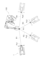
- FIG. FIG. 2 is a diagram illustrating an example of work performed by a work machine.
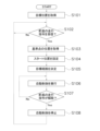
- 4 is a flowchart showing a process for automatic control of a work machine according to the first embodiment.
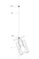
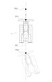
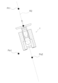
- 5 is a diagram showing the operation of the work machine in automatic control according to the first embodiment.
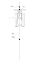
- FIG. 5 is a diagram showing the operation of the work machine in automatic control according to the first embodiment.
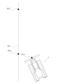
- FIG. 5 is a diagram showing the operation of the work machine in automatic control according to the first embodiment.
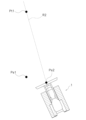
- FIG. 5 is a diagram showing the operation of the work machine in automatic control according to the first embodiment.
- FIG. 5 is a diagram showing the operation of the work machine in automatic control according to the first embodiment.
- FIG. 5 is a diagram showing the operation of the work machine in automatic control according to the first embodiment.
- FIG. 5 is a diagram showing the operation of the work machine in automatic control according to the first embodiment.
- FIG. 5 is a diagram showing the operation of the work machine in automatic control according to the first embodiment.
- FIG. 5 is a diagram showing the operation of the work machine in automatic control according to the first embodiment.
- FIG. 10 is a flowchart showing a process for automatic control of a work machine according to a second embodiment.
- 13 is a diagram showing the operation of a work machine in automatic control according to a second embodiment.
- FIG. 13 is a diagram showing the operation of a work machine in automatic control according to a second embodiment.
- FIG. 13 is a diagram showing the operation of a work machine in automatic control according to a second embodiment.
- FIG. 13 is a diagram showing the operation of a work machine in automatic control according to a second embodiment.
- FIG. 13 is a diagram showing the operation of a work machine in automatic control according to a second embodiment.
- FIG. 13 is a diagram showing the operation of a work machine in
- FIG. 13 is a flowchart showing a process for automatic control of a work machine according to a third embodiment.
- 13 is a diagram showing the operation of a work machine in automatic control according to the third embodiment.
- FIG. 13 is a diagram showing the operation of a work machine in automatic control according to the third embodiment.
- FIG. 1 is a side view showing a work machine 1 according to the embodiment.
- the work machine 1 according to this embodiment is a bulldozer.
- the work machine 1 includes a vehicle body 11 and a work implement 12.
- the vehicle body 11 includes a cab 13, an engine compartment 14, and a traveling device 15.
- a driver's seat (not shown) is arranged in the cab 13.
- the engine compartment 14 is arranged in front of the cab 13.
- the traveling device 15 is provided on the lower part of the vehicle body 11.
- the traveling device 15 includes a pair of left and right tracks 16. Note that only the left track 16 is shown in FIG. 1.
- the work machine 1 travels as the tracks 16 rotate.
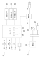
- FIG. 2 is a block diagram showing the configuration of the drive system 2 and control system 3 of the work machine 1.
- the drive system 2 includes a drive source 22, a hydraulic pump 23, and a power transmission device 24.
- the drive source 22 includes, for example, an internal combustion engine.
- the drive source 22 may also include an electric motor.
- the hydraulic pump 23 is driven by the drive source 22 and discharges hydraulic oil.
- the hydraulic oil discharged from the hydraulic pump 23 is supplied to the lift actuator 19. Note that although one hydraulic pump 23 is shown in FIG. 2, multiple hydraulic pumps may be provided.
- the power transmission device 24 transmits the driving force of the drive source 22 to the traveling device 15.
- the power transmission device 24 may be, for example, a hydrostatic transmission (HST).
- the power transmission device 24 may be, for example, a torque converter or a transmission having multiple speed change gears.
- the control system 3 includes a controller 26 and a control valve 27.
- the controller 26 is programmed to control the work machine 1 based on the acquired data.
- the controller 26 includes a memory device 28 and a processor 29.
- the processor 29 includes, for example, a CPU.
- the memory device 28 includes, for example, a memory and an auxiliary memory device.
- the memory device 28 may be, for example, a RAM or a ROM.
- the memory device 28 may be, for example, a semiconductor memory or a hard disk.
- the memory device 28 records computer instructions that are executable by the processor 29 and are used to control the work machine 1.
- the control valve 27 is a proportional control valve, and is controlled by a command signal from the controller 26.
- the control valve 27 is disposed between a hydraulic actuator, such as the lift actuator 19, and the hydraulic pump 23.
- the control valve 27 controls the flow rate of hydraulic oil supplied from the hydraulic pump 23 to the lift actuator 19.
- the control valve 27 may be a pressure proportional control valve.
- the control valve 27 may be an electromagnetic proportional control valve.
- the control system 3 includes a travel operation device 31A, a steering operation device 31B, and a work machine operation device 31C.
- the travel operation device 31A can be operated by an operator to manually control the forward and reverse travel of the work machine 1.
- the travel operation device 31A includes, for example, a travel lever. However, the travel operation device 31A may include other members such as a switch.
- the travel operation device 31A can be operated from a neutral position N1 to a forward position A1 and a reverse position B1.
- the travel operation device 31A outputs a travel command to the controller 26 in response to the operation of the operator.
- the steering operation device 31B can be operated by the operator to manually steer the work machine 1.
- the steering operation device 31B includes, for example, a steering lever.
- the steering operation device 31B may include other members such as a steering wheel or a switch.
- the steering operation device 31B can be operated in a right turning direction A2 and a left turning direction B2 from the neutral position N2.
- the steering operation device 31B outputs a steering command to the controller 26 according to the operation of the operator.
- the controller 26 controls the drive source 22 and the power transmission device 24 to drive the work machine 1 in response to a drive command from the drive operation device 31A. As a result, the work machine 1 moves forward or backward in response to the operation of the drive operation device 31A by the operator.
- the controller 26 controls the drive source 22 and the power transmission device 24 to steer the work machine 1 left or right in response to a steering command from the steering operation device 31B.
- the controller 26 turns the work machine 1 left or right by using the speed difference between the left and right tracks 16.
- the work machine 1 turns left or right in response to the operation of the steering operation device 31B by the operator.
- the controller 26 controls the control valve 27 to operate the work machine 12 in response to a work command from the work machine operating device 31C. As a result, the work machine 12 moves up and down in response to the operation of the work machine operating device 31C by the operator.
- the control system 3 includes an input device 32.
- the input device 32 includes, for example, a touch panel. However, the input device 32 may also include other devices such as switches.
- the operator can use the input device 32 to set up automatic control of the work machine 1. The automatic control of the work machine 1 will be described in detail later.
- the control system 3 includes a position sensor 34, a vehicle body sensor 35, and a work equipment sensor 36.
- the position sensor 34 is attached to the vehicle body 11.
- the position sensor 34 includes, for example, a sensor based on the Global Navigation Satellite System (GNSS).
- GNSS Global Navigation Satellite System
- the position sensor 34 detects the position and orientation of the vehicle body 11.
- the position sensor 34 outputs a detection signal indicating the position and orientation of the vehicle body 11.
- GNSS Global Navigation Satellite System
- the vehicle body sensor 35 is attached to the vehicle body 11.
- the vehicle body sensor 35 detects the attitude of the vehicle body 11.
- the vehicle body sensor 35 detects the pitch angle and roll angle of the vehicle body 11.
- the work machine sensor 36 is attached to the work machine 12.
- the work machine sensor 36 detects the attitude of the work machine 12.
- the work machine sensor 36 detects the pitch angle of the work machine 12.
- the vehicle body sensor 35 and the work equipment sensor 36 are each an IMU (Inertial Measurement Unit).
- the work equipment sensor 36 is not limited to an IMU, and may be other sensors such as an angle sensor or a cylinder stroke sensor.
- the vehicle body sensor 35 and the work equipment sensor 36 each output a detection signal indicating the detected angle.
- the controller 26 receives detection signals from the position sensor 34, the vehicle body sensor 35, and the work machine sensor 36.
- the controller 26 calculates the position and orientation of the work machine 1 based on the detection signals.
- the controller 26 performs automatic control to control the traveling direction of the work machine based on the position and orientation of the work machine 1. The automatic control of the work machine is explained below.
- the work machine 1 performs the task of collecting materials such as soil and sand from the periphery of a predetermined target position Pt1 to the target position Pt1.
- the target position Pt1 is located, for example, near the shovel 100.
- the controller 26 assists the operator in operating the work machine 1 during this task by automatically controlling the traveling direction of the work machine 1.
- FIG. 4 is a flowchart showing the process of automatic control of the work machine 1 according to the first embodiment.
- the controller 26 sets a target position Pt1.
- the target position Pt1 is set at the work site where the work machine 1 is located.
- the target position Pt1 is set by the operator operating the input device 32. For example, a map of the work site is displayed on the input device 32, and the controller 26 sets the position on the map touched by the operator as the target position Pt1.
- step S102 the controller 26 determines whether a forward driving command has been received.
- the controller 26 determines that a forward driving command has been received when the driving operation device 31A is operated to the forward position A1. If the controller 26 receives a forward driving command, the process proceeds to step S103.
- step S103 the controller 26 acquires the position of the reference point Pr1.
- the reference point Pr1 is a predetermined part included in the work machine 1. As shown in FIG. 5, the position of the reference point Pr1 is, for example, the center of the cutting edge of the blade 18.
- the controller 26 calculates the position of the reference point Pr1 based on the detection signals received from the position sensor 34, the vehicle body sensor 35, and the work machine sensor 36.
- step S104 the controller 26 sets a start position Ps1.
- the controller 26 sets the position of the reference point Pr1 when the forward travel command is received as the start position Ps1.
- step S105 the controller 26 determines a target route R1. As shown in FIG. 6, the controller 26 determines a route that passes through the start position Ps1 and the target position Pt1 as the target route R1.
- step S107 the controller 26 determines whether the forward travel command has been released.
- the controller 26 determines that the forward travel command has been released when the travel operation device 31A is operated to the neutral position N1 or reverse position B1. For example, as shown in FIG. 8, after the work machine 1 reaches the target position Pt1, the operator switches the travel operation device 31A from the forward position A1 to the reverse position B1. This causes the controller 26 to reverse the work machine 1 and determine that the forward travel command has been released. If the forward travel command has been released, processing proceeds to step S108.
- step S108 the controller 26 stops the automatic control. This allows the operator to manually control the travel direction of the work machine 1. For example, as shown in FIG. 9, the operator manually operates the travel operation device 31A and the steering operation device 31B to move the work machine 1 to a position off the target route R1. Note that if the operator operates the steering operation device 31B while automatic control is being executed, the controller 26 also stops the automatic control.
- the controller 26 receives the next forward travel command. As a result, as shown in FIG. 10, the controller 26 resets the position of the reference point Pr1 of the work machine 1 when the next forward travel command was received as the next start position Ps2. However, the controller 26 maintains the setting of the target position Pt1. The controller 26 then determines the route that passes through the next start position Ps2 and the target position Pt1 as the next target route R2.
- the controller 26 moves the work machine 1 forward in response to the forward travel command, and controls the travel direction of the work machine 1 by automatic control so that the work machine 1 travels along the target route R2.
- the work machine 1 collects materials such as soil and sand from around the target position Pt1 to the target position Pt1.
- the work machine 1 is moved to an arbitrary position and then a forward travel command is output, so that the arbitrary position is set as the start position of the target route.
- a forward travel command is output, so that the arbitrary position is set as the start position of the target route.
- an arbitrary position around the target position Pt1 is set as the start position Ps1-Ps4.
- a target route R1-R4 from the arbitrary start position Ps1-Ps4 toward the target position Pt1 is determined, and the travel direction of the work machine 1 is automatically controlled so that the work machine 1 travels along each of the target routes R1-R4. This makes it easy to collect materials from any of the start positions Ps1-Ps4 around the target position Pt1 to the target position Pt1.
- the multiple target routes R1-R12 include first to twelfth target routes R1-R12.
- the first to twelfth target routes R1-R12 each pass through the target position Pt1 and extend in different directions.
- the number of multiple target routes R1-R12 is 12.
- the number of multiple target routes is not limited to 12, and may be less than 12 or more than 12.
- step S205 the controller 26 determines whether a forward travel command has been received. If a forward travel command has been received, the controller 26 executes automatic control in step S206. As a result, as shown in FIG. 15, the controller 26 moves the work machine 1 forward and controls the travel direction of the work machine 1 so that the work machine 1 travels according to the first target route R1 selected by the input device 32.
- step S207 the controller 26 determines whether the forward driving command has been released, as in the first embodiment. If the forward driving command has been released, in step S208, the controller 26 stops automatic control, as in the first embodiment.
- the controller 26 moves the work machine 1 forward and controls the travel direction of the work machine 1 so that it travels along the next target route selected by the input device 32.
- the work machine 1 collects materials such as soil and sand from around the target position Pt1 to the target position Pt1.
- multiple target routes R1-R12 are set, each extending from a different direction toward the target position Pt1. Therefore, the travel direction of the work machine 1 is automatically controlled so that the work machine 1 travels along the target route R1 toward the target position Pt1 from a different direction. This makes it easy to collect material from around the target position Pt1 to the target position Pt1.
- FIG. 16 is a flowchart showing the process of automatic control of the work machine 1 according to the third embodiment.
- step S301 the controller 26 sets a target position Pt1.
- step S302 the controller 26 determines whether a forward travel command has been received.
- step S303 the controller 26 acquires the position of the reference point Pr1.
- Steps S301 to S303 are the same as steps S101 to S103 in the first embodiment.
- the target position Pt1 and the reference point Pr1 are the same as in the first embodiment described above.
- step S304 the controller 26 executes automatic control.
- the controller 26 controls the traveling direction of the work machine 1 so that the work machine 1 heads towards the target position Pt1.
- the controller 26 controls the traveling direction of the work machine 1 so that the reference point Pr1 of the work machine 1 heads towards the target position Pt1.
- the controller 26 does not set a target route R1, but rather controls the traveling direction of the work machine 1 so that the work machine 1 heads towards the target position Pt1.
- step S305 the controller 26 determines whether the forward driving command has been released. If the forward driving command has been released, in step S306, the controller 26 stops automatic control. Steps S305 and S306 are the same as steps S107 to S108 in the first embodiment.
- the controller 26 maintains the setting of the target position Pt1 even if the travel direction of the work machine 1 is changed according to the steering operation device 31B.
- the controller 26 receives the next forward travel command.
- the controller 26 controls the travel direction of the work machine 1 so that the work machine 1 moves again toward the target position Pt1 from the position of the work machine 1 when the next forward travel command was received.
- the work machine 1 collects materials such as soil and sand from around the target position Pt1 to the target position Pt1.
- the work machine 1 is moved to an arbitrary position and then a forward travel command is output, so that the travel direction of the work machine 1 is automatically controlled from the arbitrary position toward the target position Pt1. This makes it easy to collect material from arbitrary positions around the target position Pt1 to the target position Pt1.
- the work machine 1 is not limited to a bulldozer, and may be other vehicles such as a wheel loader or a motor grader.
- the work machine 1 may be operable remotely. In that case, the operation devices 31A-31C and the input device 32 may be disposed outside the work machine 1.
- the work machine 1 may have multiple controllers that are separate from each other. The processing by the controller 26 described above may be distributed and executed by multiple controllers.
- the automatic control process by the controller 26 is not limited to that of the above embodiment and may be modified.
- the method of setting the target position Pt1 is not limited to that of the above embodiment and may be modified.
- the controller 26 may acquire the target position Pt1 from the excavator 100.
- the controller 26 may determine the target position Pt1 from the previous work history.
- the controller 26 may determine as the target position Ot1 the position of the work machine 1 when the travel operating device 31A was switched from the forward position A1 to the reverse position B1 during the previous work.
- the reference point Pr1 is not limited to the center of the cutting edge of the blade 18, and may be another position.
- the reference point Pr1 may be provided on the vehicle body 11.
- the reference point Pr1 may be the center of rotation of the work machine 1.
- the multiple target routes R1-R12 do not have to be arranged at equal intervals.
- the method of setting the first target route R1 is not limited to that in the second embodiment described above and may be modified.
- the first target route R1 may be set by an operator operating the input device 32.
- the controller 26 may start automatic control when the target route R1 is selected.
- the controller 26 may start automatic control by an operator operating the input device 32 after the selection of the target route R1.
- materials such as soil and sand can be easily collected from the periphery of a given area into the given area by a work machine.
Landscapes
- Engineering & Computer Science (AREA)
- Mining & Mineral Resources (AREA)
- Structural Engineering (AREA)
- General Engineering & Computer Science (AREA)
- Civil Engineering (AREA)
- Remote Sensing (AREA)
- Automation & Control Theory (AREA)
- General Physics & Mathematics (AREA)
- Physics & Mathematics (AREA)
- Radar, Positioning & Navigation (AREA)
- Aviation & Aerospace Engineering (AREA)
- Control Of Position, Course, Altitude, Or Attitude Of Moving Bodies (AREA)
- Component Parts Of Construction Machinery (AREA)
- Operation Control Of Excavators (AREA)
Abstract
システムは、走行操作装置と、センサと、コントローラとを備える。走行操作装置は、作業機械を走行させる走行指令を出力する。センサは、作業機械の位置を検出する。コントローラは、作業機械の走行方向を制御する。コントローラは、目標位置を設定する。コントローラは、作業機械の位置を取得する。コントローラは、作業機械を走行させる走行指令を受信したときの作業機械の位置を、スタート位置として設定する。コントローラは、スタート位置と目標位置とを通る経路を、目標経路として決定する。コントローラは、作業機械が目標経路に従って走行するように、作業機械の走行方向を制御する。
Description
本開示は、作業機械を制御するためのシステムに関する。
従来、所定の目標経路に従って走行するように作業機械を自動制御する技術が知られている。例えば、特許文献1の作業機械の制御システムでは、互いに平行に延びる複数のスロット(目標経路)が設定される。複数のスロットは、それぞれ開始位置と終了位置とを含む。制御システムは、作業機械が複数のスロットのそれぞれに従って走行するように、作業機械を制御する。
例えば、作業機械は、第1スロットに従って、第1開始位置から第1終了位置まで、走行しながら、作業機によって掘削を行う。次に、作業機械は、第2スロットの第2開始位置に移動し、第2スロットに従って、第2開始位置から第2終了位置まで、走行しながら、作業機によって掘削を行う。上記の作業が繰り返されることで、各スロットに沿って地面が掘削される。
作業機械が行う作業には、土砂などのマテリアルを一か所に集めるものがある。例えば、整地作業を行う現場においては、整地作業によって掘削した土砂が、油圧ショベルによってダンプトラックに積み込まれる。その場合、油圧ショベルによる積込作業を効率よく行うために、掘削した土砂を、油圧ショベルの周囲から、油圧ショベルの近くの所定領域に集めることが望まれる。本開示の目的は、作業機械によって土砂などのマテリアルを所定領域の周囲から所定領域に容易に集めることにある。
本開示の第1の態様に係るシステムは、作業機械を制御するためのシステムであって、走行操作装置と、センサと、コントローラとを備える。走行操作装置は、作業機械を走行させる走行指令を出力する。センサは、作業機械の位置を検出する。コントローラは、作業機械の走行方向を制御する。コントローラは、目標位置を設定する。コントローラは、作業機械の位置を取得する。コントローラは、作業機械を走行させる走行指令を受信したときの作業機械の位置を、スタート位置として設定する。コントローラは、スタート位置と目標位置とを通る経路を、目標経路として決定する。コントローラは、作業機械が目標経路に従って走行するように、作業機械の走行方向を制御する。
第1の態様に係るシステムでは、作業機械を任意の位置に移動させてから走行指令を出力させることで、任意の位置が目標経路のスタート位置として設定される。そのため、任意のスタート位置から目標位置に向かって目標経路に従って走行するように、作業機械の走行方向が自動制御される。それにより、目標位置の周囲の任意のスタート位置から目標位置に、マテリアルを容易に集めることができる。
本開示の第2の態様に係るシステムは、作業機械を制御するためのシステムであって、センサとコントローラとを備える。センサは、作業機械の位置を検出する。コントローラは、作業機械の走行方向を制御する。コントローラは、目標位置を設定する。コントローラは、作業機械の位置を取得する。コントローラは、第1目標経路と第2目標経路とを含む複数の目標経路を決定する。第1目標経路は、目標位置を通る。第2目標経路は、目標位置を通り、第1目標経路とは異なる方位に向かって延びる。コントローラは、複数の目標経路のそれぞれに従って走行するように作業機械の走行方向を制御する。
第2の態様に係るシステムでは、互いに異なる方位から目標位置に向かって延びる複数の目標経路が設定される。そのため、互いに異なる方位から目標位置に向かって、目標経路に従って走行するように、作業機械の走行方向が自動制御される。それにより、目標位置の周囲から目標位置に、マテリアルを容易に集めることができる。
本開示の第3の態様に係るシステムは、作業機械を制御するためのシステムであって、走行操作装置と、センサと、コントローラとを備える。走行操作装置は、作業機械を走行させる走行指令を出力する。センサは、作業機械の位置を検出する。コントローラは、作業機械の走行方向を制御する。コントローラは、目標位置を設定する。コントローラは、作業機械の位置を取得する。コントローラは、作業機械を走行させる走行指令を受信した場合に、作業機械が目標位置に向かうように、作業機械の走行方向を制御する。コントローラは、走行指令が解除されても目標位置の設定を維持する。
第3態様に係るシステムでは、作業機械を任意の位置に移動させてから走行指令を出力させることで、任意の位置から目標位置に向かって作業機械の走行方向が自動制御される。それにより、目標位置の周囲の任意の位置から目標位置に、マテリアルを容易に集めることができる。
本開示によれば、作業機械によって土砂などのマテリアルを所定領域の周囲から所定領域に容易に集めることができる。
以下、実施形態に係る作業機械について、図面を参照しながら説明する。図1は、実施形態に係る作業機械1を示す側面図である。本実施形態に係る作業機械1は、ブルドーザである。作業機械1は、車体11と作業機12とを備えている。
車体11は、運転室13と、エンジン室14と、走行装置15とを含む。運転室13には、図示しない運転席が配置されている。エンジン室14は、運転室13の前方に配置されている。走行装置15は、車体11の下部に設けられている。走行装置15は、左右一対の履帯16を含む。なお、図1では、左側の履帯16のみが図示されている。履帯16が回転することによって、作業機械1が走行する。
作業機12は、車体11に取り付けられている。作業機12は、リフトフレーム17と、ブレード18と、リフトアクチュエータ19とを有する。リフトフレーム17は、車体11に対してリフト軸X1回りに回動可能に支持される。ブレード18は、車体11の前方に配置されている。ブレード18は、リフトフレーム17に支持されている。リフトアクチュエータ19は、車体11とリフトフレーム17とに連結されている。或いは、リフトアクチュエータ19は、車体11とブレード18とに連結されてもよい。リフトアクチュエータ19は、油圧シリンダである。リフトアクチュエータ19が伸縮することによって、リフトフレーム17は、上下に動作する。ブレード18は、リフトフレーム17の上下動に伴って上下に移動する。
図2は、作業機械1の駆動系2と制御システム3との構成を示すブロック図である。図2に示すように、駆動系2は、駆動源22と、油圧ポンプ23と、動力伝達装置24と、を備えている。駆動源22は、例えば内燃エンジンを含む。駆動源22は、電動モータを含んでもよい。油圧ポンプ23は、駆動源22によって駆動され、作動油を吐出する。油圧ポンプ23から吐出された作動油は、リフトアクチュエータ19に供給される。なお、図2では、1つの油圧ポンプ23が図示されているが、複数の油圧ポンプが設けられてもよい。
動力伝達装置24は、駆動源22の駆動力を走行装置15に伝達する。動力伝達装置24は、例えば、HST(Hydro Static Transmission)であってもよい。或いは、動力伝達装置24は、例えば、トルクコンバータ、或いは複数の変速ギアを有するトランスミッションであってもよい。
制御システム3は、コントローラ26と制御弁27とを備える。コントローラ26は、取得したデータに基づいて作業機械1を制御するようにプログラムされている。コントローラ26は、記憶装置28とプロセッサ29とを含む。プロセッサ29は、例えばCPUを含む。記憶装置28は、例えばメモリと補助記憶装置とを含む。記憶装置28は、例えば、RAM、或いはROMなどであってもよい。記憶装置28は、半導体メモリ、或いはハードディスクなどであってもよい。記憶装置28は、プロセッサ29によって実行可能であり作業機械1を制御するためのコンピュータ指令を記録している。
制御弁27は、比例制御弁であり、コントローラ26からの指令信号によって制御される。制御弁27は、リフトアクチュエータ19などの油圧アクチュエータと、油圧ポンプ23との間に配置される。制御弁27は、油圧ポンプ23からリフトアクチュエータ19に供給される作動油の流量を制御する。なお、制御弁27は、圧力比例制御弁であってもよい。或いは、制御弁27は、電磁比例制御弁であってもよい。
制御システム3は、走行操作装置31Aと、ステアリング操作装置31Bと、作業機操作装置31Cとを含む。走行操作装置31Aは、作業機械1の前進と後進の走行を手動操作するために、オペレータによって操作可能である。走行操作装置31Aは、例えば走行レバーを含む。ただし、走行操作装置31Aは、スイッチなどの他の部材を含んでもよい。走行操作装置31Aは、中立位置N1から前進位置A1と後進位置B1とに操作可能である。走行操作装置31Aは、オペレータの操作に応じた走行指令をコントローラ26に出力する。
ステアリング操作装置31Bは、作業機械1を手動操舵するために、オペレータによって操作可能である。ステアリング操作装置31Bは、例えばステアリングレバーを含む。ただし、ステアリング操作装置31Bは、ステアリングホイール、或いはスイッチなどの他の部材を含んでもよい。ステアリング操作装置31Bは、中立位置N2から右旋回方向A2と左旋回方向B2とに操作可能である。ステアリング操作装置31Bは、オペレータの操作に応じたステアリング指令をコントローラ26に出力する。
作業機操作装置31Cは、作業機12を手動操作するために、オペレータによって操作可能である。作業機操作装置31Cは、例えば作業機レバーを含む。ただし、作業機操作装置31Cは、スイッチなどの他の部材を含んでもよい。作業機操作装置31Cは、オペレータの操作に応じた作業指令をコントローラ26に出力する。なお、操作装置31A-33Cのそれぞれは、共通の部材によって構成されてもよい。
コントローラ26は、走行操作装置31Aからの走行指令に応じて、作業機械1を走行させるように、駆動源22及び動力伝達装置24を制御する。それにより、作業機械1は、オペレータによる走行操作装置31Aの操作に応じて、前進又は後進する。
コントローラ26は、ステアリング操作装置31Bからのステアリング指令に応じて、作業機械1を左右に操舵するように、駆動源22及び動力伝達装置24を制御する。例えば、コントローラ26は、左右の履帯16の速度差により、作業機械1を左右に旋回させる。それにより、作業機械1は、オペレータによるステアリング操作装置31Bの操作に応じて、左方又は右方に旋回する。
コントローラ26は、作業機操作装置31Cからの作業指令に応じて、作業機12を動作させるように、制御弁27を制御する。それにより、作業機12は、オペレータによる作業機操作装置31Cの操作に応じて、上下に動作する。
制御システム3は、入力装置32を含む。入力装置32は、例えばタッチパネルを含む。ただし、入力装置32は、スイッチなどの他の装置を含んでもよい。オペレータは、入力装置32を用いて、作業機械1の自動制御の設定を行うことができる。作業機械1の自動制御については、後に詳細に説明する。
制御システム3は、位置センサ34と、車体センサ35と、作業機センサ36とを含む。位置センサ34は、車体11に取り付けられている。位置センサ34は、例えば、GNSS(Global Navigation Satellite System)によるセンサを含む。位置センサ34は、車体11の位置と方位とを検出する。位置センサ34は、車体11の位置と方位とを示す検出信号を出力する。
車体センサ35は、車体11に取り付けられている。車体センサ35は、車体11の姿勢を検出する。例えば、車体センサ35は、車体11のピッチ角とロール角とを検出する。作業機センサ36は、作業機12に取り付けられている。作業機センサ36は、作業機12の姿勢を検出する。例えば、作業機センサ36は、作業機12のピッチ角を検出する。
車体センサ35と作業機センサ36とは、それぞれIMU(慣性計測装置、Inertial Measurement Unit)である。ただし、作業機センサ36は、IMUに限らず、角度センサ、或いはシリンダのストロークセンサなどの他のセンサであってもよい。車体センサ35と作業機センサ36とは、それぞれ検出した角度を示す検出信号を出力する。
コントローラ26は、位置センサ34と、車体センサ35と、作業機センサ36とから検出信号を受信する。コントローラ26は、検出信号に基づいて、作業機械1の位置と方位とを算出する。コントローラ26は、作業機械1の位置と方位とに基づいて、作業機械の走行方向を制御する自動制御を行う。以下、作業機械の自動制御について説明する。
図3に示すように、作業機械1は、土砂などのマテリアルを所定の目標位置Pt1の周囲から目標位置Pt1に集める作業を行う。目標位置Pt1は、例えばショベル100の近くに位置する。コントローラ26は、この作業において作業機械1の走行方向を自動制御することで、オペレータによる作業機械1の操作をアシストする。
図4は、第1実施形態に係る作業機械1の自動制御の処理を示すフローチャートである。図4に示すように、ステップS101で、コントローラ26は、目標位置Pt1を設定する。図5に示すように、目標位置Pt1は、作業機械1が配置された作業現場に設定される。目標位置Pt1は、オペレータが入力装置32を操作することで、設定される。例えば、入力装置32に作業現場の地図が表示され、オペレータがタッチした地図上の位置を、コントローラ26は、目標位置Pt1として設定する。
ステップS102で、コントローラ26は、前進の走行指令を受信したかを判定する。コントローラ26は、走行操作装置31Aが前進位置A1に操作されたときに、前進の走行指令を受信したと判定する。コントローラ26が前進の走行指令を受信した場合には、処理はステップS103に進む。
ステップS103では、コントローラ26は、基準点Pr1の位置を取得する。基準点Pr1は、作業機械1に含まれる所定部分である。図5に示すように、基準点Pr1の位置は、例えばブレード18の刃先の中央である。コントローラ26は、位置センサ34と、車体センサ35と、作業機センサ36とから受信した検出信号により、基準点Pr1の位置を算出する。
ステップS104で、コントローラ26は、スタート位置Ps1を設定する。コントローラ26は、前進の走行指令を受信したときの基準点Pr1の位置を、スタート位置Ps1として設定する。ステップS105で、コントローラ26は、目標経路R1を決定する。図6に示すように、コントローラ26は、スタート位置Ps1と目標位置Pt1とを通る経路を、目標経路R1として決定する。
ステップS106で、コントローラ26は、作業機械1の自動制御を実行する。図7に示すように、コントローラ26は、前進の走行指令に応じて、作業機械1を前進させると共に、作業機械1が目標経路R1に従って走行するように、作業機械1の走行方向を制御する。すなわち、コントローラ26は、作業機械1が、目標経路R1に沿って目標位置Pt1に向かって走行するように、作業機械1を操舵する。詳細には、コントローラ26は、基準点Pr1が、目標経路R1に沿って目標位置Pt1に向かって走行するように、作業機械1を旋回させる。それにより、オペレータがステアリング操作装置31Bを操作することなく、走行操作装置31Aを操作するだけで、作業機械1が目標位置Pt1に向かって旋回しながら前進する。
ステップS107で、コントローラ26は、前進の走行指令が解除されたかを判定する。コントローラ26は、走行操作装置31Aが、中立位置N1、或いは、後進位置B1に操作された場合に前進の走行指令が解除されたと判定する。例えば、図8に示すように、作業機械1が目標位置Pt1に到達した後、オペレータは、走行操作装置31Aを前進位置A1から後進位置B1に切り替える。それにより、コントローラ26は、作業機械1を後進させると共に、前進の走行指令が解除されたと判定する。前進の走行指令が解除された場合には、処理はステップS108に進む。
ステップS108では、コントローラ26は、自動制御を停止する。それにより、オペレータは、作業機械1の走行方向を手動で操作する。例えば、図9に示すように、オペレータは、走行操作装置31Aとステアリング操作装置31Bとを手動で操作し、作業機械1を目標経路R1から外れた位置に移動させる。なお、自動制御の実行中にオペレータがステアリング操作装置31Bを操作した場合にも、コントローラ26は、自動制御を停止する。
その後、オペレータが再び、走行操作装置31Aを前進位置A1に操作すると、コントローラ26は、次の前進の走行指令を受信する。それにより、図10に示すように、コントローラ26は、次の前進の走行指令を受信したときの作業機械1の基準点Pr1の位置を、次のスタート位置Ps2として再設定する。ただし、コントローラ26は、目標位置Pt1の設定を維持する。そして、コントローラ26は、次のスタート位置Ps2と目標位置Pt1とを通る経路を、次の目標経路R2として決定する。
そして、図11に示すように、コントローラ26は、前進の走行指令に応じて、作業機械1を前進させると共に、自動制御により、作業機械1が目標経路R2に従って走行するように、作業機械1の走行方向を制御する。上記の動作が繰り返されることで、作業機械1は、土砂などのマテリアルを目標位置Pt1の周囲から目標位置Pt1に集める。
以上説明した第1実施形態に係る作業機械1の自動制御では、作業機械1を任意の位置に移動させてから前進の走行指令を出力させることで、任意の位置が目標経路のスタート位置として設定される。例えば、図3に示すように、目標位置Pt1の周囲の任意の位置が、スタート位置Ps1-Ps4として設定される。そして、任意のスタート位置Ps1-Ps4から目標位置Pt1に向かう目標経路R1-R4が決定され、目標経路R1-R4のそれぞれに従って走行するように、作業機械1の走行方向が自動制御される。それにより、目標位置Pt1の周囲の任意のスタート位置Ps1-Ps4から目標位置Pt1に、マテリアルを容易に集めることができる。
次に、第2実施形態に係る作業機械1の自動制御について説明する。図12は、第2実施形態に係る作業機械1の自動制御の処理を示すフローチャートである。図12に示すように、ステップS201で、コントローラ26は、目標位置Pt1を設定する。ステップS202で、コントローラ26は、作業機械1の基準点Pr1の位置を取得する。図13に示すように、目標位置Pt1と基準点Pr1とは、上述した第1実施形態と同様である。
ステップS203で、コントローラ26は、複数の目標経路R1-R12を決定する。図14に示すように、複数の目標経路R1-R12は、目標位置Pt1を中心として放射状に延びている。複数の目標経路R1-R12は、目標位置Pt1を中心として等角度に延びている。
例えば、コントローラ26は、基準点Pr1と目標位置Pt1とを通る第1目標経路R1を決定する。また、複数の目標経路R1-R12の数が設定されており、コントローラ26は、複数の目標経路R1-R12の数から、複数の目標経路R1-R12の間の目標角度を算出する。コントローラ26は、目標位置Pt1を中心として、第1目標経路R1から目標角度ずつ間隔をおくように、他の目標経路R2-12を決定する。
例えば、図14に示す例では、複数の目標経路R1-R12は、第1~第12目標経路R1-R12を含む。第1~第12目標経路R1-R12は、それぞれ目標位置Pt1を通り互いに異なる方位に向かって延びている。なお、図14に示す例では、複数の目標経路R1-R12の数は12である。しかし、複数の目標経路の数は、12に限らず、12より少なくてもよく、12より多くてもよい。
ステップS204で、コントローラ26は、目標経路R1が選択されたかを判定する。オペレータは、例えば入力装置32を操作することで、複数の目標経路R1-R12から1つの目標経路を選択する。ここでは、第1目標経路R1が選択されたものとする。
ステップS205で、コントローラ26は、前進の走行指令を受信したかを判定する。コントローラ26は、前進の走行指令を受信した場合には、ステップS206において自動制御を実行する。それにより、図15に示すように、コントローラ26は、作業機械1を前進させると共に、入力装置32によって選択された第1目標経路R1に従って走行するように作業機械1の走行方向を制御する。
ステップS207では、コントローラ26は、第1実施形態と同様に、前進の走行指令が解除されたかを判定する。前進の走行指令が解除された場合には、ステップS208において、コントローラ26は、第1実施形態と同様に、自動制御を停止する。
次に、オペレータが次の目標経路を選択すると、ステップS204~S206で、コントローラ26は、作業機械1を前進させると共に、入力装置32によって選択された次の目標経路に従って走行するように作業機械1の走行方向を制御する。上記の動作が繰り返されることで、作業機械1は、土砂などのマテリアルを目標位置Pt1の周囲から目標位置Pt1に集める。
以上説明した第2実施形態に係る作業機械1の自動制御では、互いに異なる方位から目標位置Pt1に向かって延びる複数の目標経路R1-R12が設定される。そのため、互いに異なる方位から目標位置Pt1に向かって、目標経路R1に従って走行するように、作業機械1の走行方向が自動制御される。それにより、目標位置Pt1の周囲から目標位置Pt1に、マテリアルを容易に集めることができる。
次に、第3実施形態に係る作業機械1の自動制御について説明する。図16は、第3実施形態に係る作業機械1の自動制御の処理を示すフローチャートである。図16に示すように、ステップS301で、コントローラ26は、目標位置Pt1を設定する。ステップS302で、コントローラ26は、前進の走行指令を受信したかを判定する。ステップS303で、コントローラ26は、基準点Pr1の位置を取得する。ステップS301~S303は、第1実施形態のステップS101~S103と同様である。図17に示すように、目標位置Pt1と基準点Pr1とは、上述した第1実施形態と同様である。
ステップS304で、コントローラ26は、自動制御を実行する。コントローラ26は、作業機械1が目標位置Pt1に向かうように、作業機械1の走行方向を制御する。詳細には、図18に示すように、コントローラ26は、作業機械1の基準点Pr1が目標位置Pt1に向かうように、作業機械1の走行方向を制御する。なお、第3実施形態に係る自動制御では、コントローラ26は、目標経路R1を設定せず、作業機械1が目標位置Pt1に向かうように、作業機械1の走行方向を制御する。
ステップS305で、コントローラ26は、前進の走行指令が解除されたかを判定する。前進の走行指令が解除された場合には、ステップS306で、コントローラ26は、自動制御を停止する。ステップS305とステップS306とは、第1実施形態のステップS107~S108と同様である。
例えば、作業機械1が目標位置Pt1に到達した後、オペレータは、走行操作装置31Aとステアリング操作装置31Bとを手動で操作し、作業機械1を、前回の前進の走行指令を受信した位置と異なる位置に移動させる。このとき、コントローラ26は、ステアリング操作装置31Bに応じて作業機械1の走行方向が変更されても、目標位置Pt1の設定を維持する。
その後、オペレータが再び、走行操作装置31Aを前進位置A1に操作すると、コントローラ26は、次の前進の走行指令を受信する。それにより、コントローラ26は、次の前進の走行指令を受信したときの作業機械1の位置から、再び作業機械1が目標位置Pt1に向かって移動するように、作業機械1の走行方向を制御する。上記の動作が繰り返されることで、作業機械1は、土砂などのマテリアルを目標位置Pt1の周囲から目標位置Pt1に集める。
以上説明した第3実施形態に係る作業機械1の自動制御では、作業機械1を任意の位置に移動させてから前進の走行指令を出力させることで、任意の位置から目標位置Pt1に向かって作業機械1の走行方向が自動制御される。それにより、目標位置Pt1の周囲の任意の位置から目標位置Pt1に、マテリアルを容易に集めることができる。
以上、本発明の一実施形態について説明したが、本発明は上記実施形態に限定されるものではなく、発明の要旨を逸脱しない範囲で種々の変更が可能である。
作業機械1は、ブルドーザに限らず、ホイールローダ、モータグレーダ等の他の車両であってもよい。作業機械1は、遠隔から操作可能であってもよい。その場合、操作装置31A-31Cと入力装置32とは、作業機械1の外部に配置されてもよい。作業機械1は、互いに別体の複数のコントローラを有してもよい。上述したコントローラ26による処理は、複数のコントローラに分散して実行されてもよい。
コントローラ26による自動制御の処理は、上記の実施形態のものに限らず、変更されてもよい。目標位置Pt1を設定する方法は、上記の実施形態のものに限らず変更されてもよい。例えば、コントローラ26は、ショベル100から目標位置Pt1を取得してもよい。コントローラ26は、前回の作業履歴から目標位置Pt1を決定してもよい。例えば、コントローラ26は、前回の作業において、走行操作装置31Aが前進位置A1から後進位置B1に切り替えられたときの作業機械1の位置を、目標位置Ot1として決定してもよい。
基準点Pr1は、ブレード18の刃先の中央に限らず、他の位置であってもよい。例えば、基準点Pr1は、車体11に設けられてもよい。基準点Pr1は、作業機械1の旋回中心であってもよい。
第2実施形態において、複数の目標経路R1-R12は、等間隔に配置されなくてもよい。第1目標経路R1の設定方法は、上記の第2実施形態のものに限らず、変更されてもよい。例えば、第1目標経路R1は、オペレータが入力装置32を操作することで、設定されてもよい。第2実施形態において、コントローラ26は、目標経路R1が選択された場合に、自動制御を開始してもよい。或いは、コントローラ26は、目標経路R1の選択後にオペレータが入力装置32を操作することで、自動制御を開始してもよい。
本開示によれば、作業機械によって土砂などのマテリアルを所定領域の周囲から所定領域に容易に集めることができる。
1:作業機械
26:コントローラ
31A:走行操作装置
31B:ステアリング操作装置
32:入力装置
34:位置センサ
26:コントローラ
31A:走行操作装置
31B:ステアリング操作装置
32:入力装置
34:位置センサ
Claims (13)
- 作業機械を制御するためのシステムであって、
前記作業機械を走行させる走行指令を出力する走行操作装置と、
前記作業機械の位置を検出するセンサと、
前記作業機械の走行方向を制御するコントローラと、
を備え、
前記コントローラは、
目標位置を設定し、
前記作業機械の位置を取得し、
前記作業機械を走行させる走行指令を受信したときの前記作業機械の位置を、スタート位置として設定し、
前記スタート位置と前記目標位置とを通る経路を、前記目標経路として決定し、
前記作業機械が前記目標経路に従って走行するように、前記作業機械の走行方向を制御する、
システム。 - 前記コントローラは、前記走行指令が解除されても前記目標位置の設定を維持する、
請求項1に記載のシステム。 - 前記コントローラは、
前回の前記走行指令が解除された後、次の走行指令を受信した場合には、前記次の走行指令を受信したときの前記作業機械の位置を、次のスタート位置として再設定し、
前記次のスタート位置と前記目標位置とを通る経路を、次の目標経路として決定する、
請求項1に記載のシステム。 - 前記走行操作装置は、中立位置から前進位置と後進位置とに手動操作可能であり、
前記コントローラは、
前記走行操作装置が前記前進位置に操作されることで前記走行指令を受信したときの前記作業機械の位置を、前記目標経路のスタート位置として設定し、
前記走行操作装置が前記中立位置又は前記後進位置に操作された場合には、前記走行指令が解除されたと判定する、
請求項3に記載のシステム。 - 前記作業機械を手動で操舵するために操作可能なステアリング操作装置をさらに備え、
前記コントローラは、
前回の前記走行指令が解除された後、前記ステアリング操作装置の操作に応じて前記作業機械が前回の前記目標経路から外れた位置に移動しても、前記目標位置の設定を維持し、
次の走行指令を受信した場合には、前記次の走行指令を受信したときの前記作業機械の位置を、次のスタート位置として再設定し、
前記次のスタート位置と前記目標位置とを通る経路を、次の目標経路として決定する、
請求項1に記載のシステム。 - 作業機械を制御するためのシステムであって、
前記作業機械の位置を検出するセンサと、
前記作業機械の走行方向を制御するコントローラと、
を備え、
前記コントローラは、
目標位置を設定し、
前記作業機械の位置を取得し、
前記目標位置を通る第1目標経路と、前記目標位置を通り前記第1目標経路とは異なる方位に向かって延びる第2目標経路とを含む複数の目標経路を決定し、
前記複数の目標経路のそれぞれに従って走行するように前記作業機械の走行方向を制御する、
システム。 - 前記コントローラは、前記目標位置を中心として放射状に延びるように、前記複数の目標経路を決定する、
請求項6に記載のシステム。 - 前記コントローラは、前記目標位置を中心として等角度に延びるように、前記複数の目標経路を決定する、
請求項6に記載のシステム。 - オペレータによって操作可能な入力装置をさらに備え、
前記コントローラは、前記複数の目標経路のうち、前記入力装置によって選択された目標経路に従って走行するように前記作業機械の走行方向を制御する、
請求項6に記載のシステム。 - 作業機械を制御するためのシステムであって、
前記作業機械を走行させる走行指令を出力する走行操作装置と、
前記作業機械の位置を検出するセンサと、
前記作業機械の走行方向を制御するコントローラと、
を備え、
前記コントローラは、
目標位置を設定し、
前記作業機械の位置を取得し、
前記作業機械を走行させる走行指令を受信した場合に、前記作業機械が前記目標位置に向かうように、前記作業機械の走行方向を制御し、
前記走行指令が解除されても前記目標位置の設定を維持する、
システム。 - 前記コントローラは、
前回の前記走行指令が解除された後、次の走行指令を受信した場合には、前記作業機械が再び前記目標位置に向かうように、前記作業機械の走行方向を制御する、
請求項10に記載のシステム。 - 前記走行操作装置は、中立位置から前進位置と後進位置とに手動操作可能であり、
前記コントローラは、
前記走行操作装置が前記前進位置に操作されることで前記走行指令を受信した場合に、前記作業機械が前記目標位置に向かうように、前記作業機械の走行方向を制御し、
前記走行操作装置が前記中立位置又は前記後進位置に操作された場合には、前記走行指令が解除されたと判定する、
請求項11に記載のシステム。 - 前記作業機械を手動で操舵するために操作可能なステアリング操作装置をさらに備え、
前記コントローラは、
前回の前記走行指令が解除された後、前記ステアリング操作装置に応じて前記作業機械の走行方向が変更されても、前記目標位置の設定を維持し、
次の走行指令を受信した場合には、前記作業機械が再び前記目標位置に向かうように、前記作業機械の走行方向を制御する、
請求項10に記載のシステム。
Applications Claiming Priority (2)
| Application Number | Priority Date | Filing Date | Title |
|---|---|---|---|
| JP2023105823A JP2025005596A (ja) | 2023-06-28 | 2023-06-28 | 作業機械を制御するためのシステム |
| JP2023-105823 | 2023-06-28 |
Publications (1)
| Publication Number | Publication Date |
|---|---|
| WO2025004497A1 true WO2025004497A1 (ja) | 2025-01-02 |
Family
ID=93938592
Family Applications (1)
| Application Number | Title | Priority Date | Filing Date |
|---|---|---|---|
| PCT/JP2024/014704 Ceased WO2025004497A1 (ja) | 2023-06-28 | 2024-04-11 | 作業機械を制御するためのシステム |
Country Status (2)
| Country | Link |
|---|---|
| JP (1) | JP2025005596A (ja) |
| WO (1) | WO2025004497A1 (ja) |
Families Citing this family (1)
| Publication number | Priority date | Publication date | Assignee | Title |
|---|---|---|---|---|
| USD1119680S1 (en) * | 2024-09-27 | 2026-03-24 | Harry Winston Sa | Collar pin |
Citations (5)
| Publication number | Priority date | Publication date | Assignee | Title |
|---|---|---|---|---|
| JPH0522805U (ja) * | 1991-08-30 | 1993-03-26 | 株式会社アイチコーポレーシヨン | 油圧走行車の走行制御装置 |
| WO2016167375A1 (ja) * | 2016-04-28 | 2016-10-20 | 株式会社小松製作所 | 作業機械の管理装置 |
| JP6253567B2 (ja) * | 2014-11-17 | 2017-12-27 | ヤンマー株式会社 | 作業車両の移動システム |
| WO2020183906A1 (ja) * | 2019-03-14 | 2020-09-17 | ヤンマー株式会社 | 経路生成システム |
| WO2023047885A1 (ja) * | 2021-09-24 | 2023-03-30 | 日立建機株式会社 | 作業機械の制御システムおよび作業機械 |
-
2023
- 2023-06-28 JP JP2023105823A patent/JP2025005596A/ja active Pending
-
2024
- 2024-04-11 WO PCT/JP2024/014704 patent/WO2025004497A1/ja not_active Ceased
Patent Citations (5)
| Publication number | Priority date | Publication date | Assignee | Title |
|---|---|---|---|---|
| JPH0522805U (ja) * | 1991-08-30 | 1993-03-26 | 株式会社アイチコーポレーシヨン | 油圧走行車の走行制御装置 |
| JP6253567B2 (ja) * | 2014-11-17 | 2017-12-27 | ヤンマー株式会社 | 作業車両の移動システム |
| WO2016167375A1 (ja) * | 2016-04-28 | 2016-10-20 | 株式会社小松製作所 | 作業機械の管理装置 |
| WO2020183906A1 (ja) * | 2019-03-14 | 2020-09-17 | ヤンマー株式会社 | 経路生成システム |
| WO2023047885A1 (ja) * | 2021-09-24 | 2023-03-30 | 日立建機株式会社 | 作業機械の制御システムおよび作業機械 |
Also Published As
| Publication number | Publication date |
|---|---|
| JP2025005596A (ja) | 2025-01-17 |
Similar Documents
| Publication | Publication Date | Title |
|---|---|---|
| US10443214B2 (en) | Control system for work vehicle, control method, and work vehicle | |
| AU2017268675B2 (en) | System and method for modifying a material movement plan | |
| JP6818696B2 (ja) | 作業車両の制御システム、方法、及び作業車両 | |
| JP7312563B2 (ja) | 作業機械の制御システム、及び制御方法 | |
| CN117083432A (zh) | 作业机械的行驶系统以及作业机械的控制方法 | |
| CN113359540A (zh) | 用于移动式机器的自动模式恢复系统 | |
| CN113518843B (zh) | 作业机械 | |
| JP2017186875A5 (ja) | ||
| CN119486925A (zh) | 工程机械以及用于控制工程机械的方法 | |
| WO2025004497A1 (ja) | 作業機械を制御するためのシステム | |
| WO2022130756A1 (ja) | 複数の作業機械を制御するためのシステム及び方法 | |
| JP7352911B2 (ja) | 運搬車両を制御するためのシステム及び方法 | |
| JP7379281B2 (ja) | 作業機械を制御するためのシステム、方法、および作業機械 | |
| CN113302363B (zh) | 作业机械的控制系统 | |
| JP7555220B2 (ja) | 作業機械、作業機械を制御するための方法、及びシステム | |
| WO2025057670A1 (ja) | 作業機械を制御するためのシステムおよび方法 | |
| WO2025004438A1 (ja) | 作業機械を制御するためのシステム及び方法 | |
| WO2026094385A1 (ja) | 作業機械を制御するためのシステム、及び、方法 | |
| WO2025004435A1 (ja) | 作業機械を制御するためのシステム及び方法 | |
| WO2025192073A1 (ja) | 作業機械を制御するためのシステム、方法、及び作業機械 | |
| WO2024204511A1 (ja) | 制御装置、制御方法および作業機械 | |
| WO2025177778A1 (ja) | 作業機械を制御するためのシステム、方法、及び作業機械 | |
| WO2024202978A1 (ja) | 制御装置、制御方法および作業機械 | |
| WO2024204413A1 (ja) | 制御装置、制御方法および作業機械 | |
| WO2025142449A1 (ja) | 作業機械を制御するためのシステム、方法、及び作業機械 |
Legal Events
| Date | Code | Title | Description |
|---|---|---|---|
| 121 | Ep: the epo has been informed by wipo that ep was designated in this application |
Ref document number: 24831372 Country of ref document: EP Kind code of ref document: A1 |
|
| NENP | Non-entry into the national phase |
Ref country code: DE |