WO2025004495A1 - 内袋付容器詰め飲料の製造方法 - Google Patents
内袋付容器詰め飲料の製造方法 Download PDFInfo
- Publication number
- WO2025004495A1 WO2025004495A1 PCT/JP2024/014425 JP2024014425W WO2025004495A1 WO 2025004495 A1 WO2025004495 A1 WO 2025004495A1 JP 2024014425 W JP2024014425 W JP 2024014425W WO 2025004495 A1 WO2025004495 A1 WO 2025004495A1
- Authority
- WO
- WIPO (PCT)
- Prior art keywords
- inner bag
- beverage
- container
- filling
- packed
- Prior art date
- Legal status (The legal status is an assumption and is not a legal conclusion. Google has not performed a legal analysis and makes no representation as to the accuracy of the status listed.)
- Ceased
Links
Images



Classifications
-
- A—HUMAN NECESSITIES
- A23—FOODS OR FOODSTUFFS; TREATMENT THEREOF, NOT COVERED BY OTHER CLASSES
- A23L—FOODS, FOODSTUFFS OR NON-ALCOHOLIC BEVERAGES, NOT OTHERWISE PROVIDED FOR; PREPARATION OR TREATMENT THEREOF
- A23L2/00—Non-alcoholic beverages; Dry compositions or concentrates therefor; Preparation or treatment thereof
-
- B—PERFORMING OPERATIONS; TRANSPORTING
- B65—CONVEYING; PACKING; STORING; HANDLING THIN OR FILAMENTARY MATERIAL
- B65D—CONTAINERS FOR STORAGE OR TRANSPORT OF ARTICLES OR MATERIALS, e.g. BAGS, BARRELS, BOTTLES, BOXES, CANS, CARTONS, CRATES, DRUMS, JARS, TANKS, HOPPERS, FORWARDING CONTAINERS; ACCESSORIES, CLOSURES, OR FITTINGS THEREFOR; PACKAGING ELEMENTS; PACKAGES
- B65D25/00—Details of other kinds or types of rigid or semi-rigid containers
- B65D25/38—Devices for discharging contents
- B65D25/40—Nozzles or spouts
- B65D25/48—Separable nozzles or spouts
-
- B—PERFORMING OPERATIONS; TRANSPORTING
- B65—CONVEYING; PACKING; STORING; HANDLING THIN OR FILAMENTARY MATERIAL
- B65D—CONTAINERS FOR STORAGE OR TRANSPORT OF ARTICLES OR MATERIALS, e.g. BAGS, BARRELS, BOTTLES, BOXES, CANS, CARTONS, CRATES, DRUMS, JARS, TANKS, HOPPERS, FORWARDING CONTAINERS; ACCESSORIES, CLOSURES, OR FITTINGS THEREFOR; PACKAGING ELEMENTS; PACKAGES
- B65D77/00—Packages formed by enclosing articles or materials in preformed containers, e.g. boxes, cartons, sacks or bags
- B65D77/04—Articles or materials enclosed in two or more containers disposed one within another
Definitions
- the present invention relates to a method for producing a beverage packed in a container with an inner bag, in which a beverage is filled in the inner bag of a container with an inner bag, the container including an inner bag and an outer container.
- the present invention was made with a focus on these problems, and aims to provide a method for producing a beverage packed in a container with an inner bag that can sufficiently reduce the oxygen concentration in the inner bag and fill the inner bag with a beverage in a short period of time.
- a manufacturing method for a packed beverage in a container with an inner bag is a method for manufacturing a packed beverage in a container with an inner bag, in which a beverage is filled in the inner bag of a container with an inner bag, which includes an inner bag and an outer container, and includes an oxygen inhalation process of inhaling oxygen from within the inner bag, and a beverage filling process of filling the inner bag with a beverage after the oxygen inhalation process.
- beverages packed in containers with inner pouches and containing low amounts of dissolved oxygen can be produced in a short period of time.
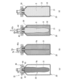
- FIG. 1 is a schematic cross-sectional view illustrating one embodiment of a container with an inner bag used in a manufacturing method for a container-packed beverage with an inner bag according to one aspect of the present invention, in which (a) shows the entire container with an inner bag, (b) shows the outer container, (c) shows the inner bag, and (d) shows the filling lid, each shown in cross-section along the axis.
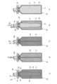
- 1A to 1E are diagrams illustrating a first embodiment of a method for producing a packed beverage in a container with an inner bag according to one aspect of the present invention.
- 1A to 1E are diagrams illustrating a second embodiment of a method for producing a packed beverage in a container with an inner bag according to one aspect of the present invention.
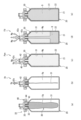
- 1A to 1E are diagrams illustrating a method for producing a packed beverage in a container with an inner bag according to Comparative Example 1.
- 13A to 13D are diagrams illustrating a method for producing a packed beverage in a container with an inner bag according to Comparative Example 2.
- 13A to 13E are diagrams illustrating a method for producing a packed beverage in a container with an inner bag according to Comparative Example 3.
- the container with inner bag 10 of this embodiment includes an outer container 20, an inner bag 30 contained inside the outer container 20, and a filling lid 40 used for filling and attached so as to cover the upper openings of the outer container 20 and the inner bag 30.
- the capacity of the container with inner bag 10 can be set to, for example, 3L, 5L, 8L, 10L, etc.
- the outer container 20 of this embodiment is a relatively strong, rigid container made of metal (for example, aluminum), glass, hard plastic, or the like. As shown in FIG. 2( b ), the outer container 20 has a disk-shaped (planar) bottom surface 21, a side wall portion 22 extending upward from the periphery of the bottom surface 21 in a hollow cylindrical shape, a truncated cone portion 23 narrowing in diameter upward from the annular upper edge portion of the side wall portion 22, a small-diameter cylindrical portion 24 extending upward from the annular upper edge portion of the truncated cone portion 23, and a flange portion 25 extending laterally in an annular shape from the upper edge portion of the small-diameter cylindrical portion 24.
- a disk-shaped (planar) bottom surface 21 As shown in FIG. 2( b ), the outer container 20 has a disk-shaped (planar) bottom surface 21, a side wall portion 22 extending upward from the periphery of the bottom surface 21 in a hollow cylindrical shape, a t
- the inner bag 30 of this embodiment has a bag body 31 and a cylindrical mouthpiece 32 integrally fixed to an upper opening of the bag body 31.
- the bag body 31 of this embodiment is configured in a bag shape from a transparent or semi-transparent resin film or the like that has flexibility and gas barrier properties (and light blocking properties), and is formed so as to be expandable into a tightly fitting shape following the inner surface of the outer container 20 when expanded within the outer container 20.
- the mouth part 32 of the inner bag 30 is a relatively robust part made of hard plastic and elastomer (sealing part), etc., and the cylindrical lower end flange part is fixed tightly to the upper opening of the bag body 31, and the necessary sealing function is provided on the outer surface of the flange part.
- the filling lid 40 is used only when manufacturing a containerized beverage with an inner bag, and after the beverage is filled, the container 10 with inner bag is removed from the fixed-volume filling device and transferred to a capper, where it is replaced with a distribution lid (not shown).
- the filling lid 40 of this embodiment has a disk-shaped lid main body 41, and the underside of the lid main body 41 is formed with a concave annular portion 44 that can be attached and detached to the flange portion 25 of the outer container 20 by a screw.
- a filling plug 42 that protrudes upward is provided at the upper central part of the lid body 41, and a connecting plug 43 that protrudes downward at the lower central part of the lid body 41 and is detachably attached to and connectable to the nozzle portion 32 of the inner bag 30.
- the filling plug 42 has a double-tube structure, and is configured such that, when the filling plug 42 is attached, an inner tube portion of the double tube communicates with the inside of the inner bag 30.
- the filling plug 42 is also configured such that an outer tube portion of the double tube communicates between the outside of the inner bag 30 and the inside of the outer container 20.
- the upper part of the filling plug 42 is connected via piping to a fixed-volume filling device (not shown) including a well-known filler bowl, and the container 10 with inner bag is set in the fixed-volume filling device.
- an auxiliary plug 45 is attached to the side of the filling plug 42 on the upper part of the lid body 41.
- the auxiliary plug 45 has an on-off valve that can open and close the flow path inside itself.
- the lower opening of the auxiliary plug 45 is provided so as to communicate between the outside of the inner bag 30 and the inside of the outer container 20. This allows the necessary intake and degassing between the outside of the inner bag 30 and the inside of the outer container 20 through the lower opening of the auxiliary plug 45 at the desired timing.
- the manufacturing method of a packed beverage in a container with an inner bag according to this embodiment is for producing a packed beverage in a container with an inner bag by filling the inside of the inner bag 30 with a beverage D for the container with inner bag 10 including the inner bag 30 and the outer container 20 described above.
- the cap portion 32 of the inner bag 30 is attached to the connecting plug 43 of the filling lid 40, and the bag body 31 of the inner bag 30 is inserted into the inside of the outer container 20 from the upper opening of the outer container 20 in a hanging state.
- the concave annular portion 44 of the lid body 41 is fitted into the flange portion 25 at the upper end of the outer container 20, and the filling lid 40 is attached to the top of the outer container 20 to assemble the container with inner bag 10, and the assembled container with inner bag 10 is set in a fixed-quantity filling device.
- air (oxygen) Xg is contained in the hanging bag body 31.
- a vacuum pump (not shown) is connected to the inner tube portion 42u of the filling plug 42 having a double tube structure, and the air (oxygen) Xg is sucked from inside the inner bag 30 by the vacuum pump (oxygen suction step Ax). Atmospheric pressure is applied to the outside of the inner bag 30.
- the filling valve of the quantitative filling device opens, and carbon dioxide (or other inert gas (nitrogen, argon, etc., the same below)) Ng in the filler bowl (product liquid tank) of the quantitative filling device flows into the inner bag 30 of the container with inner bag 10, filling the inner bag 30 with carbon dioxide (inert gas) Ng and inflating it (inner bag pressure application process Pan).
- carbon dioxide or other inert gas (nitrogen, argon, etc., the same below)
- the supply valve for beverage D on the quantitative filling device side opens, beverage D enters the inner bag 30, and the carbon dioxide (inert gas) Ng in the inner bag 30 moves to the filler bowl through the filling valve.
- the beverage D is filled into the inner bag 30 while discharging the carbon dioxide (inert gas) Ng from within the inner bag 30 (beverage filling process Fd).
- the beverage D is a soft drink or alcoholic beverage (sparkling beverage) containing carbon dioxide gas (carbon dioxide), and in this embodiment is a beer beverage.
- air (oxygen) Xg is sucked in from inside the inner bag 30 by a vacuum pump in the oxygen suction process Ax, so that a container-packed beverage with an inner bag having a low amount of dissolved oxygen Xg can be produced in a short period of time.
- a gas Ng such as air or carbon dioxide is filled between the outer container 20 and the inner bag 30, and as a counterpressure, the gas Ng such as air or carbon dioxide is applied within the outer container 20 while being discharged, thereby filling the beverage D into the inner bag 30 (pressure application process Pas within the outer container). That is, in the second embodiment, after the oxygen suction step Ax, as shown in Fig. 2C, gas (air or gas such as carbon dioxide) is introduced between the outside of the inner bag 30 and the inside of the outer container 20 (inner-container pressure application step Pas). In the example of the second embodiment, air is basically used since it does not come into direct contact with the beverage, and the air is introduced from the auxiliary plug 45.
- the inner tube portion 42u of the filling plug 42 is connected to a filler bowl (not shown) via piping, and as shown in FIG. 3(d), beverage D is filled into the inner bag 30 while applying a pressure equivalent to the pressure in the filler bowl or the liquid delivery pressure as a counterpressure (beverage filling process Fd).
- the beverage D is filled into the inner bag 30 while applying back pressure by the carbon dioxide (inert gas) Ng in the outer container 20 introduced by the auxiliary plug 45 (pressure application step Pas in the outer container to beverage filling step Fd).
- the beverage D is filled into the inner bag 30 as shown in FIG. 1(e).
- air (oxygen) Xg is sucked in from inside the inner bag 30 by a vacuum pump in the oxygen suction process Ax, so that a packed beverage in a container with an inner bag with a low amount of dissolved oxygen Xg can be produced in a short period of time.
- the first and second embodiments are methods for producing a container-packed beverage with an inner bag, which include an oxygen inhalation process Ax in which oxygen Xg is inhaled from within the inner bag 30, and a beverage filling process Fd in which a beverage D is filled into the inner bag 30 after the oxygen inhalation process Ax.
- an inner bag pressure application process Pan is included in which an inert gas Ng is flowed into the inner bag 30 to apply a pressure equivalent to the pressure in the filler bowl or the liquid delivery pressure to the inner bag 30, and in the subsequent beverage filling process Fd, the inner bag 30 is filled with beverage D while the inert gas Ng in the inner bag 30 is discharged [Invention 2 (Method A)]. Therefore, the manufacturing method of the container-packed beverage with inner bag according to the first embodiment is suitable for filling the inner bag 30 with a carbonated beverage such as beer as the beverage D while preventing or suppressing foaming. Furthermore, in the first embodiment, the beverage D is a beverage containing carbon dioxide, and the inert gas is carbon dioxide, so that the method is suitable for application to a beer beverage [Invention 3 (Method A)].
- a process Pas for applying pressure inside the outer container is included in which gas (air Xg or carbon dioxide Ng) is introduced between the inner bag 30 and the outer container 20 to apply a pressure equivalent to the pressure inside the filler bowl or the liquid delivery pressure, and in the beverage filling process Fd, the beverage D is filled into the inner bag 30 while discharging the gas between the inner bag 30 and the outer container 20.
- gas air Xg or carbon dioxide Ng
- the beverage D in the beverage filling process Fd, is filled into the inner bag 30 while applying back pressure by the gas (air Xg or carbon dioxide Ng) inside the outer container 20 (pressure application process Pas inside the outer container), so that, as in the first embodiment, it is possible to produce a container-packed beverage with an inner bag having a low amount of dissolved oxygen Xg in a short time while preventing or suppressing foaming of carbonated beverages such as beer [Invention 4 (Method B)].
- a container with inner bag 10 including an inner bag 30 and an outer container 20 was prepared with a capacity of 3 liters.
- beer was filled into the inner bag 30 as beverage D, and the time required for filling and the amount of dissolved oxygen in the beverage packed in the inner bag-equipped container produced were measured.
- the amount of dissolved oxygen was measured by sampling beverage D from the inner bag-equipped container 10 and using a gas analyzer (Orbisphere 510 and Orbisphere 31120A manufactured by Hach).
- Example 1 is an example corresponding to the first embodiment shown in FIG.
- Example 1 in the oxygen suction step Ax in the first embodiment, air Xg in the inner bag 30 of the container with inner bag 10 was sucked in by a vacuum pump (-0.06 MPa, 1 s) (FIG. 2(b)).
- a vacuum pump (-0.06 MPa, 1 s)
- carbon dioxide gas Ng was injected into the inner bag 30, and a pressure equivalent to the pressure in the filler bowl was applied to the inner bag 30 as a counter pressure (FIG. 2(c)).
- beer beverage was filled into the inner bag 30 as beverage D while discharging carbon dioxide gas Ng from the inner bag 30 (FIGS. 2(d)-(e)).
- Example 2 is an example corresponding to the second embodiment shown in FIG.
- Example 2 in the oxygen suction step Ax in the second embodiment, the air Xg in the inner bag 30 of the container with inner bag 10 was sucked in by a vacuum pump (-0.06 MPa, 15 s) (FIG. 3(b)). After that, the air Xg was put between the inner bag 30 and the outer container 20, and a pressure equivalent to the pressure in a filler bowl (not shown) was applied as a counter pressure (FIG. 3(c)). After that, the beer beverage was filled into the inner bag 30 as the beverage D while discharging the air Xg between the inner bag 30 and the outer container 20 (FIGS. 3(d)-(e)).
- Comparative Example 1 (Prior Art) 4(a) to (e) show a method for producing a packed beverage in a container with an inner bag according to Comparative Example 1.
- Comparative Example 1 first, as shown in Fig. 1A, air Xg was injected between the inner bag 30 of the container 10 with an inner bag and the outer container 20 to increase the pressure inside the outer container 20.
- Fig. 1B the opening of the inner bag 30 was opened to discharge the air Xg inside the inner bag 30.
- air Xg was further introduced between the inner bag 30 and the outer container 20, and a pressure equivalent to the pressure in the filler bowl was applied as a counterpressure between the inner bag 30 and the outer container 20.
- beer was filled into the inner bag 30 as beverage D, while the air Xg between the inner bag 30 and the outer container 20 was discharged.
- Comparative Example 2 (Simultaneous Suction and Pressure) 5(a) to (d) show a method for producing a packed beverage in a container with an inner bag according to Comparative Example 2.
- Comparative Example 2 starting from the initial installation state (FIG. 1(a)) in the first or second embodiment, as shown in FIG. 1(b), the air Xg in the inner bag 30 of the container 10 with inner bag was sucked in by a vacuum pump (-0.06 MPa, 15 s), and at the same time, air Xg was introduced between the inner bag 30 and the outer container 20, applying a pressure equivalent to the pressure in the filler bowl. After that, as shown in FIG. 1(c) to (d), beer was filled into the inner bag 30 as the beverage D, while the air Xg between the inner bag 30 and the outer container 20 was discharged.
- Comparative Example 3 pressure ⁇ suction 6(a) to (e) show a method for producing a packed beverage in a container with an inner bag according to Comparative Example 3.
- Comparative Example 3 as shown in Fig. 1(a), first, air Xg was introduced between the inner bag 30 of the container 10 with inner bag and the outer container 20 to increase the pressure inside the outer container 20.
- the air Xg inside the inner bag 30 was sucked out by a decompression pump (-0.06 MPa, 15 s).
- Fig. 1C air Xg was further introduced between the inner bag 30 and the outer container 20, and a pressure equivalent to the pressure in the filler bowl was applied as a counter pressure.
- beer was filled into the inner bag 30 while discharging the air Xg between the inner bag 30 and the outer container 20.
- Table 1 shows the time required for filling and the amount of dissolved oxygen in the 10-pack of beverage D in the container with inner bag produced for the above-mentioned Examples 1 and 2 and Comparative Examples 1-3.
- Example 1 Although carbon dioxide gas Ng is used, beer beverage can be filled into the inner bag 30 in the shortest time. Furthermore, in Example 1, the amount of dissolved oxygen is also at the lowest level of 128.9 ⁇ g/l. Furthermore, in Example 2, although the filling time is at the same level as in Comparative Example 2, it can be seen that the amount of dissolved oxygen can be reduced to the smallest. Thus, the amount of dissolved oxygen in the beverages produced by the above-mentioned first and second embodiments can be reduced to 150 ⁇ g/l or less [Invention 6 (Methods A and B)].
- the method for producing a packed beverage in a container with an inner bag according to the present invention makes it possible to produce a packed beverage in a container with an inner bag having a low amount of dissolved oxygen in a short period of time.
- the method for producing a packed beverage in a container with an inner bag according to the present invention is not limited to the above-described embodiment, and it goes without saying that various modifications are possible without departing from the spirit of the present invention.
Landscapes
- Engineering & Computer Science (AREA)
- Mechanical Engineering (AREA)
- Health & Medical Sciences (AREA)
- Nutrition Science (AREA)
- Life Sciences & Earth Sciences (AREA)
- Chemical & Material Sciences (AREA)
- Food Science & Technology (AREA)
- Polymers & Plastics (AREA)
- Packages (AREA)
- Details Of Rigid Or Semi-Rigid Containers (AREA)
- Non-Alcoholic Beverages (AREA)
Abstract
内袋内の酸素濃度を十分に低下させ且つ短時間で充填可能な、内袋付容器詰め飲料の製造方法を提供する。この内袋付容器詰め飲料の製造方法は、内袋(30)と外装容器(20)とを含む内袋付容器(10)の内袋(30)に飲料(D)が充填された内袋付容器詰め飲料を製造する方法であって、内袋(30)内から酸素(Xg)を吸引する酸素吸引工程(Ax)と、酸素吸引工程(Ax)の後に、内袋(30)内に飲料(D)を充填する飲料充填工程(Fd)と、を含む。
Description
本発明は、内袋と外装容器とを含む内袋付容器の内袋に飲料が充填された内袋付容器詰め飲料の製造方法に関する。
従来から、ビール等の飲料を輸送、保管するための容器として、金属製の樽が多く用いられている。従来の樽を用いた飲料注出方式は、樽内に二酸化炭素を流入させて飲料に圧力をかけることで飲料を樽から注出する。
これに対し、近年では、KeyKeg(Lightweight Containers社製)に代表されるような内袋付容器も利用されており、内袋付容器の開発も進められている(例えば特許文献1参照)。
この種の内袋付容器では、外装容器と飲料が充填された内袋との間に空気を流入させて、内袋に周囲から圧力をかけることで飲料を注出する。そのため、内袋付容器を用いた飲料注出方式によれば、注出用の二酸化炭素が不要であること、外装容器の洗浄が不要であること、などの利点がある。
これに対し、近年では、KeyKeg(Lightweight Containers社製)に代表されるような内袋付容器も利用されており、内袋付容器の開発も進められている(例えば特許文献1参照)。
この種の内袋付容器では、外装容器と飲料が充填された内袋との間に空気を流入させて、内袋に周囲から圧力をかけることで飲料を注出する。そのため、内袋付容器を用いた飲料注出方式によれば、注出用の二酸化炭素が不要であること、外装容器の洗浄が不要であること、などの利点がある。
ここで、この種の内袋付容器の内袋に飲料を充填する場合、例えば、事前に内袋と外装容器との間に空気を入れて外装容器内の圧力を高めた後に、内袋を開放することで内袋内の空気(酸素)を排気できる。その後、一定の圧力となるように、内袋と外装容器との間の空気を排出しながら内袋内に飲料を充填する。
しかしながら、上記の飲料充填方法では、一度の排気工程のみによっては、内袋内の空気(酸素)を十分に排出できず、内袋内に充填した飲料の品質が劣化する懸念がある。また、上記の飲料充填方法において、内袋内の空気(酸素)を、飲料の品質保持に十分な酸素濃度まで低下させようとすれば、2~3回程度、同様の排気工程を行う必要があり、内袋内への飲料の充填に時間がかかるという問題がある。
しかしながら、上記の飲料充填方法では、一度の排気工程のみによっては、内袋内の空気(酸素)を十分に排出できず、内袋内に充填した飲料の品質が劣化する懸念がある。また、上記の飲料充填方法において、内袋内の空気(酸素)を、飲料の品質保持に十分な酸素濃度まで低下させようとすれば、2~3回程度、同様の排気工程を行う必要があり、内袋内への飲料の充填に時間がかかるという問題がある。
そこで、本発明は、このような問題点に着目してなされたものであって、内袋内の酸素濃度を十分に低下させ且つ短時間で内袋内に飲料を充填可能な、内袋付容器詰め飲料の製造方法を提供することを課題とする。
本発明者らが鋭意検討した結果、内袋内に飲料を充填する前に、内袋内から空気を吸引することで、短時間で内袋内の酸素濃度を低下可能なことを見出した。
すなわち、上記課題を解決するために、本発明の一態様に係る内袋付容器詰め飲料の製造方法は、内袋と外装容器とを含む内袋付容器の内袋に飲料が充填された内袋付容器詰め飲料を製造する方法であって、前記内袋内から酸素を吸引する酸素吸引工程と、前記酸素吸引工程の後に、前記内袋内に飲料を充填する飲料充填工程と、を含む。
すなわち、上記課題を解決するために、本発明の一態様に係る内袋付容器詰め飲料の製造方法は、内袋と外装容器とを含む内袋付容器の内袋に飲料が充填された内袋付容器詰め飲料を製造する方法であって、前記内袋内から酸素を吸引する酸素吸引工程と、前記酸素吸引工程の後に、前記内袋内に飲料を充填する飲料充填工程と、を含む。
本発明によれば、短時間で溶存酸素量の少ない内袋付容器詰め飲料を製造できる。
以下、本発明の一実施形態について、図面を適宜参照しつつ説明する。なお、図面は模式的なものである。そのため、厚みと平面寸法との関係、比率等は現実のものとは異なることに留意すべきであり、図面相互間においても互いの寸法の関係や比率が異なる部分が含まれている。
また、以下に示す実施形態は、本発明の技術的思想を具体化するための装置や方法を例示するものであって、本発明の技術的思想は、構成部品の材質、形状、構造、配置等を下記の実施形態に特定するものではない。
また、以下に示す実施形態は、本発明の技術的思想を具体化するための装置や方法を例示するものであって、本発明の技術的思想は、構成部品の材質、形状、構造、配置等を下記の実施形態に特定するものではない。
[内袋付容器]
まず、各実施形態の内袋付容器詰め飲料の製造に用いる内袋付容器の一実施形態について図1を参照しつつ説明する。
図1(a)に示すように、本実施形態の内袋付容器10は、外装容器20と、外装容器20の内部に収容される内袋30と、充填に用いられ、外装容器20および内袋30の上部開口を覆うように装着される充填用蓋40と、を含んで構成される。内袋付容器10の容量としては、例えば、3L、5Lの他、8L、10L等の容量を設定できる。
まず、各実施形態の内袋付容器詰め飲料の製造に用いる内袋付容器の一実施形態について図1を参照しつつ説明する。
図1(a)に示すように、本実施形態の内袋付容器10は、外装容器20と、外装容器20の内部に収容される内袋30と、充填に用いられ、外装容器20および内袋30の上部開口を覆うように装着される充填用蓋40と、を含んで構成される。内袋付容器10の容量としては、例えば、3L、5Lの他、8L、10L等の容量を設定できる。
本実施形態の外装容器20は、金属(例えばアルミニウム)やガラス乃至は硬質プラスチック等からなる比較的堅牢な剛性容器である。
外装容器20は、同図(b)に示すように、円盤状(平面視)をなす底面21と、底面21の周囲から上方に向けて中空円筒状に伸びる側壁部22と、側壁部22の環状上縁部から上方に縮径する円錐台部23と、円錐台部23の環状上縁部から上方に張り出す小径円筒部24と、小径円筒部24の上縁部から側方に環状に張り出すフランジ部25と、を有する。
外装容器20は、同図(b)に示すように、円盤状(平面視)をなす底面21と、底面21の周囲から上方に向けて中空円筒状に伸びる側壁部22と、側壁部22の環状上縁部から上方に縮径する円錐台部23と、円錐台部23の環状上縁部から上方に張り出す小径円筒部24と、小径円筒部24の上縁部から側方に環状に張り出すフランジ部25と、を有する。
本実施形態の内袋30は、同図(c)に示すように、袋体31と、袋体31の上部開口部に一体に固着された円筒状の口金部32と、を有する。本実施形態の袋体31は、可撓性並びにガスバリア性(及び遮光性)を有する透明ないし半透明の樹脂フィルム等から袋状に構成されており、外装容器20内での展伸時には、外装容器20の内面に倣った密着形状まで展伸可能に形成されている。
内袋30の口金部32は、硬質プラスチック及びエラストマー(シール部)等からなる比較的堅牢な部品であって、円筒状の下端フランジ部が、袋体31の上部開口部に隙間なく固着されるとともに、必要なシール機能がフランジ部外面に設けられている。内袋30は、外装容器20内に装着時には、外装容器20の小径円筒部24の内周面に、これに対応する外周部分が所期の位置に保持される。
内袋30の口金部32は、硬質プラスチック及びエラストマー(シール部)等からなる比較的堅牢な部品であって、円筒状の下端フランジ部が、袋体31の上部開口部に隙間なく固着されるとともに、必要なシール機能がフランジ部外面に設けられている。内袋30は、外装容器20内に装着時には、外装容器20の小径円筒部24の内周面に、これに対応する外周部分が所期の位置に保持される。
充填用蓋40は、内袋付容器詰め飲料の製造時にのみ用いられるものであり、飲料を充填後は、定量充填装置から内袋付容器10がはずされてキャッパに転送され、流通用蓋(不図示)に置換される。
本実施形態の充填用蓋40は、同図(d)に示すように、円盤状の蓋本体41を有し、蓋本体41の下面には、外装容器20のフランジ部25にねじによって着脱可能な凹円環状部44が形成されている。
また、蓋本体41の中央上部には、上方に張り出す充填用プラグ42が設けられるとともに、蓋本体41の中央下部には、内袋30の口金部32に着脱可能且つ連通可能な連結プラグ43が下方に向けて張り出している。
本実施形態の充填用蓋40は、同図(d)に示すように、円盤状の蓋本体41を有し、蓋本体41の下面には、外装容器20のフランジ部25にねじによって着脱可能な凹円環状部44が形成されている。
また、蓋本体41の中央上部には、上方に張り出す充填用プラグ42が設けられるとともに、蓋本体41の中央下部には、内袋30の口金部32に着脱可能且つ連通可能な連結プラグ43が下方に向けて張り出している。
充填用プラグ42は二重管構造を有し、充填用プラグ42の装着時に、二重管の内管部が内袋30の内部に連通するように構成される。また、充填用プラグ42は、二重管の外管部が内袋30の外側と外装容器20の内部との間に連通するように構成される。充填用プラグ42の上部は、周知のフィラーボウルを含む定量充填装置(不図示)に配管を介して接続され、定量充填装置に内袋付容器10がセットされる。
さらに、蓋本体41の上部には、充填用プラグ42の側部に、補助プラグ45が付設されている。補助プラグ45は、自身内部の流路を開閉可能な開閉弁を有する。補助プラグ45の下部開口が、内袋30の外側と外装容器20の内部との間に連通するように設けられる。これにより、補助プラグ45の下部開口から、内袋30の外側と外装容器20の内部との間に対して、必要な吸気および脱気が所期のタイミングにて可能になっている。
さらに、蓋本体41の上部には、充填用プラグ42の側部に、補助プラグ45が付設されている。補助プラグ45は、自身内部の流路を開閉可能な開閉弁を有する。補助プラグ45の下部開口が、内袋30の外側と外装容器20の内部との間に連通するように設けられる。これにより、補助プラグ45の下部開口から、内袋30の外側と外装容器20の内部との間に対して、必要な吸気および脱気が所期のタイミングにて可能になっている。
[第一実施形態(方法A)]
次に、第一実施形態の内袋付容器詰め飲料の製造方法について図2を参照しつつ説明する。本実施形態の内袋付容器詰め飲料の製造方法は、上述した、内袋30と外装容器20とを含む内袋付容器10に対し、内袋30の内部に飲料Dを充填して内袋付容器詰め飲料を製造するものである。
次に、第一実施形態の内袋付容器詰め飲料の製造方法について図2を参照しつつ説明する。本実施形態の内袋付容器詰め飲料の製造方法は、上述した、内袋30と外装容器20とを含む内袋付容器10に対し、内袋30の内部に飲料Dを充填して内袋付容器詰め飲料を製造するものである。
まず、図2(a)に示すように、充填用蓋40の連結プラグ43に、内袋30の口金部32を装着し、その内袋30の袋体31を垂下した状態で外装容器20の上部開口から外装容器20の内部に挿入する。その後、外装容器20上端のフランジ部25に蓋本体41の凹円環状部44を嵌め合わせ、充填用蓋40を外装容器20上部に装着して上記内袋付容器10を組み立て、組み立てられた内袋付容器10が定量充填装置にセットされる。
このとき、同図に示すように、垂下状態の袋体31内には、空気(酸素)Xgが入った状態にある。これに対し、第一実施形態では、同図(b)に示すように、二重管構造の充填用プラグ42の内管部42uに減圧ポンプ(不図示)を接続して、内袋30内から減圧ポンプによって空気(酸素)Xgを吸引する(酸素吸引工程Ax)。内袋30の外側には大気圧が掛かっている。
このとき、同図に示すように、垂下状態の袋体31内には、空気(酸素)Xgが入った状態にある。これに対し、第一実施形態では、同図(b)に示すように、二重管構造の充填用プラグ42の内管部42uに減圧ポンプ(不図示)を接続して、内袋30内から減圧ポンプによって空気(酸素)Xgを吸引する(酸素吸引工程Ax)。内袋30の外側には大気圧が掛かっている。
次いで、同図(c)に示すように、上記酸素吸引工程Axの後に、定量充填装置の充填バルブが開いて、内袋付容器10の内袋30内に、定量充填装置のフィラーボウル(製品液タンク)内の二酸化炭素(若しくはその他の不活性ガス(窒素、アルゴンなど、以下同じ))Ngが流入され、内袋30内を二酸化炭素(不活性ガス)Ngで満たして膨らませる(内袋内圧力印可工程Pan)。次いで、同図(d)に示すように、上記定量充填装置のフィラーボウル(製品液タンク)内の圧力又は送液圧と同等の圧力をカウンタープレッシャとして内袋30内の二酸化炭素(不活性ガス)Ngによって印加しつつ(内袋内圧力印可工程Pan)、定量充填装置側の飲料Dの供給バルブが開いて飲料Dが内袋30内に入り、内袋30内の二酸化炭素(不活性ガス)Ngは充填バルブを通してフィラーボウルに移動する。
これにより、同図(d)~(e)に示すように、内袋30内の二酸化炭素(不活性ガス)Ngを排出しながら内袋30内に飲料Dが充填される(飲料充填工程Fd)。なお、飲料Dは炭酸ガス(二酸化炭素)を含有する清涼飲料水又はアルコール飲料(発泡飲料)であって、本実施形態ではビール飲料である。
第一実施形態に係る内袋付容器詰め飲料の製造方法であれば、酸素吸引工程Axにおいて内袋30内から減圧ポンプによって空気(酸素)Xgを吸引するので、短時間で溶存酸素Xg量の少ない内袋付容器詰め飲料を製造できる。
第一実施形態に係る内袋付容器詰め飲料の製造方法であれば、酸素吸引工程Axにおいて内袋30内から減圧ポンプによって空気(酸素)Xgを吸引するので、短時間で溶存酸素Xg量の少ない内袋付容器詰め飲料を製造できる。
[第二実施形態(方法B)]
次に、第二実施形態の内袋付容器詰め飲料の製造方法について図3を参照しつつ説明する。
まず、上記第一実施形態同様にして、図3(a)に示すように、上記内袋付容器10を組み立てる。このとき、内袋30内には、空気(酸素)Xgが入った状態にある。そのため、第二実施形態においても、上記第一実施形態同様に、図3(b)に示すように、内袋30内から減圧ポンプによって空気(酸素)Xgを吸引する(酸素吸引工程Ax)。
ここで、上記第一実施形態では、内袋30内に二酸化炭素(不活性ガス)Ngを流入させて内袋30を膨らませた後に(内袋内圧力印可工程Pan)、内袋30内の二酸化炭素(不活性ガス)Ngを排出しつつ内袋30内に飲料Dを充填する(内袋内圧力印可工程Pan~飲料充填工程Fd)例を示した。
次に、第二実施形態の内袋付容器詰め飲料の製造方法について図3を参照しつつ説明する。
まず、上記第一実施形態同様にして、図3(a)に示すように、上記内袋付容器10を組み立てる。このとき、内袋30内には、空気(酸素)Xgが入った状態にある。そのため、第二実施形態においても、上記第一実施形態同様に、図3(b)に示すように、内袋30内から減圧ポンプによって空気(酸素)Xgを吸引する(酸素吸引工程Ax)。
ここで、上記第一実施形態では、内袋30内に二酸化炭素(不活性ガス)Ngを流入させて内袋30を膨らませた後に(内袋内圧力印可工程Pan)、内袋30内の二酸化炭素(不活性ガス)Ngを排出しつつ内袋30内に飲料Dを充填する(内袋内圧力印可工程Pan~飲料充填工程Fd)例を示した。
これに対し、第二実施形態では、外装容器20と内袋30との間に、空気または二酸化炭素などのガスNgを充填し、カウンタープレッシャとして、外装容器20内にて空気または二酸化炭素などのガスNgで背圧を掛けつつ排出して内袋30内に飲料Dを充填する点が相違する(外装容器内圧力印可工程Pas)。
つまり、第二実施形態では、上記酸素吸引工程Axの後に、同図(c)に示すように、内袋30の外側と外装容器20の内部との間に、ガス(空気若しくは二酸化炭素などのガス)を流入する(外装容器内圧力印可工程Pas)。第二実施形態の例では、飲料に直接接触しないため基本的には空気を用い、補助プラグ45から空気を導入する。
つまり、第二実施形態では、上記酸素吸引工程Axの後に、同図(c)に示すように、内袋30の外側と外装容器20の内部との間に、ガス(空気若しくは二酸化炭素などのガス)を流入する(外装容器内圧力印可工程Pas)。第二実施形態の例では、飲料に直接接触しないため基本的には空気を用い、補助プラグ45から空気を導入する。
次いで、充填用プラグ42の内管部42uに対し、配管を介してフィラーボウル(不図示)に接続し、同図(d)に示すように、フィラーボウル内の圧力又は送液圧と同等の圧力をカウンタープレッシャとして印加しつつ、内袋30内に飲料Dを充填する(飲料充填工程Fd)。
このように、第二実施形態では、飲料充填工程Fdにおいて、補助プラグ45で導入した外装容器20内の二酸化炭素(不活性ガス)Ngによって背圧を掛けつつ内袋30内に飲料Dを充填する(外装容器内圧力印可工程Pas~飲料充填工程Fd)。これにより、同図(e)に示すように、内袋30内に飲料Dが充填される。
第二実施形態に係る内袋付容器詰め飲料の製造方法であれば、上記第一実施形態同様、酸素吸引工程Axにおいて内袋30内から減圧ポンプによって空気(酸素)Xgを吸引するので、短時間で溶存酸素Xg量の少ない内袋付容器詰め飲料を製造できる。
このように、第二実施形態では、飲料充填工程Fdにおいて、補助プラグ45で導入した外装容器20内の二酸化炭素(不活性ガス)Ngによって背圧を掛けつつ内袋30内に飲料Dを充填する(外装容器内圧力印可工程Pas~飲料充填工程Fd)。これにより、同図(e)に示すように、内袋30内に飲料Dが充填される。
第二実施形態に係る内袋付容器詰め飲料の製造方法であれば、上記第一実施形態同様、酸素吸引工程Axにおいて内袋30内から減圧ポンプによって空気(酸素)Xgを吸引するので、短時間で溶存酸素Xg量の少ない内袋付容器詰め飲料を製造できる。
次に、実施形態の内袋付容器詰め飲料の製造方法の作用効果について説明する。
図2および図3に示したように、第一および第二実施形態は、内袋30内から酸素Xgを吸引する酸素吸引工程Axと、酸素吸引工程Axの後に、内袋30内に飲料Dを充填する飲料充填工程Fdと、を含む内袋付容器詰め飲料の製造方法である。
これにより、第一および第二実施形態に係る内袋付容器詰め飲料の製造方法によれば、酸素吸引工程Axにおいて内袋30内から減圧ポンプによって空気(酸素)Xgを吸引するので、短時間で溶存酸素Xg量の少ない内袋付容器詰め飲料を製造できる[発明1(方法A、B)]。
図2および図3に示したように、第一および第二実施形態は、内袋30内から酸素Xgを吸引する酸素吸引工程Axと、酸素吸引工程Axの後に、内袋30内に飲料Dを充填する飲料充填工程Fdと、を含む内袋付容器詰め飲料の製造方法である。
これにより、第一および第二実施形態に係る内袋付容器詰め飲料の製造方法によれば、酸素吸引工程Axにおいて内袋30内から減圧ポンプによって空気(酸素)Xgを吸引するので、短時間で溶存酸素Xg量の少ない内袋付容器詰め飲料を製造できる[発明1(方法A、B)]。
特に、第一実施形態では、内袋30内からの酸素吸引工程Axの後に、内袋30内に不活性ガスNgを流入させて、フィラーボウル内の圧力又は送液圧と同等の圧力を内袋30内にかける内袋内圧力印可工程Panを含み、続く飲料充填工程Fdにおいて、内袋30内の不活性ガスNgを排出しつつ内袋30内に飲料Dを充填する[発明2(方法A)]。
そのため、第一実施形態に係る内袋付容器詰め飲料の製造方法であれば、飲料Dとして、ビール等の炭酸飲料を泡立てることを防止または抑制しつつ内袋30内に充填する上で好適である。さらに、第一実施形態においては、飲料Dは二酸化炭素を含有する飲料であり、不活性ガスは二酸化炭素なので、ビール飲料に適用する上で好適である[発明3(方法A)]。
そのため、第一実施形態に係る内袋付容器詰め飲料の製造方法であれば、飲料Dとして、ビール等の炭酸飲料を泡立てることを防止または抑制しつつ内袋30内に充填する上で好適である。さらに、第一実施形態においては、飲料Dは二酸化炭素を含有する飲料であり、不活性ガスは二酸化炭素なので、ビール飲料に適用する上で好適である[発明3(方法A)]。
また、第二実施形態では、図3に示したように、酸素吸引工程Axの後に、内袋30と外装容器20との間にガス(空気Xg若しくは二酸化炭素Ng)を流入させて、フィラーボウル内の圧力又は送液圧と同等の圧力をかける外装容器内圧力印可工程Pasを含み、飲料充填工程Fdにおいて、内袋30と外装容器20との間のガスを排出しつつ内袋30内に飲料Dを充填する。
つまり、第二実施形態では、飲料充填工程Fdにおいて、外装容器20内のガス(空気Xg若しくは二酸化炭素Ng)によって背圧を掛けつつ内袋30内に飲料Dを充填する(外装容器内圧力印可工程Pas)ので、上記第一実施形態同様、ビール等の炭酸飲料を泡立てることを防止または抑制しつつ、短時間で溶存酸素Xg量の少ない内袋付容器詰め飲料を製造できる[発明4(方法B)]。
特に、第二実施形態において、背圧を掛けるための外装容器20内のガスとして、空気Xgを用いることにより、二酸化炭素Ngを用いた場合と比較して、一層の低コストで内袋付容器詰め飲料を製造できる[発明5(方法B)]。
特に、第二実施形態において、背圧を掛けるための外装容器20内のガスとして、空気Xgを用いることにより、二酸化炭素Ngを用いた場合と比較して、一層の低コストで内袋付容器詰め飲料を製造できる[発明5(方法B)]。
次に、上記実施形態で説明した内袋付容器詰め飲料の製造方法について、実施例及び比較例に基づき説明する。ここでは、内袋30と外装容器20とを含んで構成される内袋付容器10として、容量が3リットルのものを用意した。
以下の実施例及び比較例に記載の方法で、飲料Dとしてビールを内袋30内に充填し、充填に要した時間、および、製造した内袋付容器詰め飲料における飲料中の溶存酸素量を測定した。溶存酸素量は、内袋付容器10から飲料Dを採取し、ガスアナライザ(Hach社製Orbisphere 510及びOrbisphere 31120A)を用いて測定した。
以下の実施例及び比較例に記載の方法で、飲料Dとしてビールを内袋30内に充填し、充填に要した時間、および、製造した内袋付容器詰め飲料における飲料中の溶存酸素量を測定した。溶存酸素量は、内袋付容器10から飲料Dを採取し、ガスアナライザ(Hach社製Orbisphere 510及びOrbisphere 31120A)を用いて測定した。
〈実施例1(方法A)〉
実施例1は、図2に示した、上記第一実施形態に対応する実施例である。
実施例1では、上記第一実施形態における酸素吸引工程Axにおいて、内袋付容器10の内袋30内の空気Xgを減圧ポンプ(-0.06MPa、1s)で吸引した(図2(b))。その後に、内袋30内に炭酸ガスNgを噴射して、フィラーボウル内の圧力と同等の圧力をカウンタープレッシャとして内袋30内に印加した(図2(c))。その後、内袋30内の炭酸ガスNgを排出しつつ内袋30内に飲料Dとしてビール飲料を充填した(図2(d)-(e))。
実施例1は、図2に示した、上記第一実施形態に対応する実施例である。
実施例1では、上記第一実施形態における酸素吸引工程Axにおいて、内袋付容器10の内袋30内の空気Xgを減圧ポンプ(-0.06MPa、1s)で吸引した(図2(b))。その後に、内袋30内に炭酸ガスNgを噴射して、フィラーボウル内の圧力と同等の圧力をカウンタープレッシャとして内袋30内に印加した(図2(c))。その後、内袋30内の炭酸ガスNgを排出しつつ内袋30内に飲料Dとしてビール飲料を充填した(図2(d)-(e))。
〈実施例2(方法B)〉
実施例2は、図3に示した、上記第二実施形態に対応する実施例である。
実施例2では、上記第二実施形態における酸素吸引工程Axにおいて、内袋付容器10の内袋30内の空気Xgを減圧ポンプ(-0.06MPa、15s)で吸引した(図3(b))。その後に、内袋30と外装容器20との間に空気Xgを入れて、不図示のフィラーボウル内の圧力と同等の圧力をカウンタープレッシャとして印加した(図3(c))。その後、内袋30と外装容器20との間の空気Xgを排出しながら内袋30内に飲料Dとしてビール飲料を充填した(図3(d)-(e))。
実施例2は、図3に示した、上記第二実施形態に対応する実施例である。
実施例2では、上記第二実施形態における酸素吸引工程Axにおいて、内袋付容器10の内袋30内の空気Xgを減圧ポンプ(-0.06MPa、15s)で吸引した(図3(b))。その後に、内袋30と外装容器20との間に空気Xgを入れて、不図示のフィラーボウル内の圧力と同等の圧力をカウンタープレッシャとして印加した(図3(c))。その後、内袋30と外装容器20との間の空気Xgを排出しながら内袋30内に飲料Dとしてビール飲料を充填した(図3(d)-(e))。
〈比較例1(従来技術)〉
図4(a)~(e)に比較例1による内袋付容器詰め飲料の製造方法を示す。
比較例1では、まず、同図(a)に示すように、内袋付容器10の内袋30と外装容器20との間に空気Xgを入れて外装容器20内の圧力を高めた。次いで、同図(b)に示すように、内袋30の開口部を開放することで内袋30内の空気Xgを排出した。
その後、同図(c)に示すように、内袋30と外装容器20との間にさらに空気Xgを入れて、フィラーボウル内の圧力と同等の圧力をカウンタープレッシャとして内袋30と外装容器20との間にかけた。その後、同図(d)~(e)に示すように、内袋30と外装容器20との間の空気Xgを排出しつつ内袋30内に飲料Dとしてビール飲料を充填した。
図4(a)~(e)に比較例1による内袋付容器詰め飲料の製造方法を示す。
比較例1では、まず、同図(a)に示すように、内袋付容器10の内袋30と外装容器20との間に空気Xgを入れて外装容器20内の圧力を高めた。次いで、同図(b)に示すように、内袋30の開口部を開放することで内袋30内の空気Xgを排出した。
その後、同図(c)に示すように、内袋30と外装容器20との間にさらに空気Xgを入れて、フィラーボウル内の圧力と同等の圧力をカウンタープレッシャとして内袋30と外装容器20との間にかけた。その後、同図(d)~(e)に示すように、内袋30と外装容器20との間の空気Xgを排出しつつ内袋30内に飲料Dとしてビール飲料を充填した。
〈比較例2(吸引加圧同時)〉
図5(a)~(d)に比較例2による内袋付容器詰め飲料の製造方法を示す。
比較例2では、上記第一ないし第二実施形態での初期設置状態(同図(a))からはじめて、同図(b)に示すように、内袋付容器10の内袋30内の空気Xgを減圧ポンプ(-0.06MPa、15s)で吸引すると同時に、内袋30と外装容器20との間に空気Xgを入れて、フィラーボウル内の圧力と同等の圧力をかけた。その後、同図(c)~(d)に示すように、内袋30と外装容器20との間の空気Xgを排出しつつ内袋30内に飲料Dとしてビール飲料を充填した。
図5(a)~(d)に比較例2による内袋付容器詰め飲料の製造方法を示す。
比較例2では、上記第一ないし第二実施形態での初期設置状態(同図(a))からはじめて、同図(b)に示すように、内袋付容器10の内袋30内の空気Xgを減圧ポンプ(-0.06MPa、15s)で吸引すると同時に、内袋30と外装容器20との間に空気Xgを入れて、フィラーボウル内の圧力と同等の圧力をかけた。その後、同図(c)~(d)に示すように、内袋30と外装容器20との間の空気Xgを排出しつつ内袋30内に飲料Dとしてビール飲料を充填した。
〈比較例3(加圧→吸引)〉
図6(a)~(e)に比較例3による内袋付容器詰め飲料の製造方法を示す。
比較例3では、同図(a)に示すように、まず、内袋付容器10の内袋30と外装容器20との間に空気Xgを入れて外装容器20内の圧力を高めた。次いで、同図(b)に示すように、内袋30内の空気Xgを減圧ポンプ(-0.06MPa、15s)で吸引した。
その後、同図(c)に示すように、内袋30と外装容器20との間にさらに空気Xgを入れて、フィラーボウル内の圧力と同等の圧力をカウンタープレッシャとして印加した。その後、同図(d)~(e)に示すように、内袋30と外装容器20との間の空気Xgを排出しつつ内袋30内にビールを充填した。
図6(a)~(e)に比較例3による内袋付容器詰め飲料の製造方法を示す。
比較例3では、同図(a)に示すように、まず、内袋付容器10の内袋30と外装容器20との間に空気Xgを入れて外装容器20内の圧力を高めた。次いで、同図(b)に示すように、内袋30内の空気Xgを減圧ポンプ(-0.06MPa、15s)で吸引した。
その後、同図(c)に示すように、内袋30と外装容器20との間にさらに空気Xgを入れて、フィラーボウル内の圧力と同等の圧力をカウンタープレッシャとして印加した。その後、同図(d)~(e)に示すように、内袋30と外装容器20との間の空気Xgを排出しつつ内袋30内にビールを充填した。
上述した実施例1,2及び比較例1-3について、充填に要した時間と、製造した内袋付容器10詰め飲料Dの溶存酸素量を表1に示す。

表1に示す結果から、実施例1では、炭酸ガスNgを使用するものの、最も短時間で内袋30内にビール飲料を充填できることがわかる。また、実施例1では、溶存酸素量も、128.9μg/lと、最も低い水準となっている。また、実施例2では、充填時間は、比較例2と同水準ではあるものの、溶存酸素量を最も少なくできることがわかる。このように、上述した第一および第二実施形態により製造された飲料の溶存酸素量は、150μg/l以下とすることができる[発明6(方法A、B)]。
これに対し、比較例1-3に示す製造方法では、いずれの方法においても、溶存酸素量が高いことがわかる。換言すれば、比較例1-3に示す製造方法によって、実施例1,2と同等の溶存酸素量を達成しようとすれば、内袋30内から空気を排出する操作を複数回繰り返す必要があり、実施例1,2に比べて充填時間は長くなってしまうことになる。
以上、実施形態および実施例並びに比較例に基づき説明したように、本発明に係る内袋付容器詰め飲料の製造方法によれば、短時間で溶存酸素量の少ない内袋付容器詰め飲料を製造できる。
なお、本発明に係る内袋付容器詰め飲料の製造方法は、上記実施形態に限定されるものではなく、本発明の趣旨を逸脱しなければ種々の変形が可能であることは勿論である。
なお、本発明に係る内袋付容器詰め飲料の製造方法は、上記実施形態に限定されるものではなく、本発明の趣旨を逸脱しなければ種々の変形が可能であることは勿論である。
10 内袋付容器
20 外装容器
30 内袋
40 充填用蓋
D 飲料
Xg 空気(酸素)
Ng 二酸化炭素(不活性ガス)
Ax 酸素吸引工程
Fd 飲料充填工程
Pan 内袋内圧力印可工程
Pas 外装容器内圧力印可工程
20 外装容器
30 内袋
40 充填用蓋
D 飲料
Xg 空気(酸素)
Ng 二酸化炭素(不活性ガス)
Ax 酸素吸引工程
Fd 飲料充填工程
Pan 内袋内圧力印可工程
Pas 外装容器内圧力印可工程
Claims (6)
- 内袋と外装容器とを含む内袋付容器の内袋に飲料が充填された内袋付容器詰め飲料を製造する方法であって、
前記内袋内から酸素を吸引する酸素吸引工程と、
前記酸素吸引工程の後に、前記内袋内に飲料を充填する飲料充填工程と、を含む、
ことを特徴とする内袋付容器詰め飲料の製造方法。 - 前記酸素吸引工程の後に、前記内袋内に不活性ガスを流入させてカウンタープレッシャを内袋内にかける内袋内圧力印可工程を含み、
前記飲料充填工程において、前記内袋内の不活性ガスを排出しながら前記内袋内に飲料を充填する、請求項1に記載の内袋付容器詰め飲料の製造方法。 - 前記飲料は、二酸化炭素を含有する飲料であり、
前記不活性ガスは、二酸化炭素である、請求項2に記載の内袋付容器詰め飲料の製造方法。 - 前記酸素吸引工程の後に、前記内袋と前記外装容器との間にガスを流入させてカウンタープレッシャを前記外装容器内にかける外装容器内圧力印可工程を含み、
前記飲料充填工程において、前記内袋と前記外装容器との間のガスを排出しながら前記内袋内に飲料を充填する、請求項1に記載の内袋付容器詰め飲料の製造方法。 - 前記ガスは、空気である、請求項4に記載の内袋付容器詰め飲料の製造方法。
- 製造後の前記飲料中の溶存酸素量が、150μg/l以下である、請求項1に記載の内袋付容器詰め飲料の製造方法。
Applications Claiming Priority (2)
| Application Number | Priority Date | Filing Date | Title |
|---|---|---|---|
| JP2023-106512 | 2023-06-28 | ||
| JP2023106512A JP2025006006A (ja) | 2023-06-28 | 2023-06-28 | 内袋付容器詰め飲料の製造方法 |
Publications (1)
| Publication Number | Publication Date |
|---|---|
| WO2025004495A1 true WO2025004495A1 (ja) | 2025-01-02 |
Family
ID=93938572
Family Applications (1)
| Application Number | Title | Priority Date | Filing Date |
|---|---|---|---|
| PCT/JP2024/014425 Ceased WO2025004495A1 (ja) | 2023-06-28 | 2024-04-09 | 内袋付容器詰め飲料の製造方法 |
Country Status (2)
| Country | Link |
|---|---|
| JP (1) | JP2025006006A (ja) |
| WO (1) | WO2025004495A1 (ja) |
Citations (2)
| Publication number | Priority date | Publication date | Assignee | Title |
|---|---|---|---|---|
| JP2016203988A (ja) * | 2015-04-15 | 2016-12-08 | フジテクノ株式会社 | 飲料容器、飲料充填方法、および、飲料注出方法 |
| WO2020017617A1 (ja) * | 2018-07-18 | 2020-01-23 | 株式会社ダイゾー | 二重加圧容器、吐出製品、吐出部材、ディスペンサーシステムおよび吐出製品の製造方法 |
-
2023
- 2023-06-28 JP JP2023106512A patent/JP2025006006A/ja active Pending
-
2024
- 2024-04-09 WO PCT/JP2024/014425 patent/WO2025004495A1/ja not_active Ceased
Patent Citations (2)
| Publication number | Priority date | Publication date | Assignee | Title |
|---|---|---|---|---|
| JP2016203988A (ja) * | 2015-04-15 | 2016-12-08 | フジテクノ株式会社 | 飲料容器、飲料充填方法、および、飲料注出方法 |
| WO2020017617A1 (ja) * | 2018-07-18 | 2020-01-23 | 株式会社ダイゾー | 二重加圧容器、吐出製品、吐出部材、ディスペンサーシステムおよび吐出製品の製造方法 |
Non-Patent Citations (2)
| Title |
|---|
| ANONYMOUS: "[FOR PROFESSIONALS] A COMPREHENSIVE GUIDE TO FILLING A KEY KEG", CRAFT DRINKS, 9 May 2019 (2019-05-09), XP093253080, Retrieved from the Internet <URL:http://craftdrinks.jp/2017/04/09/%E3%80%90%E3%83%97%E3%83%AD%E5%90%91%E3%81%91%E3%80%91%E3%82%AD%E3%83%BC%E3%82%B1%E3%82%B0%E5%85%85%E5%A1%AB%E5%A4%A7%E8%A7%A3%E8%AA%AC/> * |
| ANONYMOUS: "[FOR PROFESSIONALS] EXPLANATION OF HOW TO FILL A KEY KEG ~IF IT HAS EFFERVESCENCE~", CRAFT DRINKS, 19 April 2017 (2017-04-19), XP093253079, Retrieved from the Internet <URL:https://craftdrinks.jp/2017/04/19/%E3%80%90%E3%83%97%E3%83%AD%E5%90%91%E3%81%91%E3%80%91%E3%82%AD%E3%83%BC%E3%82%B1%E3%82%B0%E5%85%85%E5%A1%AB%E5%A4%A7%E8%A7%A3%E8%AA%AC-%E3%80%9C%E7%99%BA%E6%B3%A1%E6%80%A7%E3%81%82%E3%82%8A%E3%81%AE/> * |
Also Published As
| Publication number | Publication date |
|---|---|
| JP2025006006A (ja) | 2025-01-17 |
Similar Documents
| Publication | Publication Date | Title |
|---|---|---|
| CN1166541C (zh) | 带有吸嘴的碳酸饮料容器 | |
| US5566730A (en) | Gas actuator assembly | |
| JP5031143B2 (ja) | 飲料、特にビールを貯蔵し分配するための容器 | |
| CN100383034C (zh) | 瓶塞替换装置和瓶塞替换方法 | |
| CN104495736A (zh) | 用于分销和分配饮料的系统和方法 | |
| US5433346A (en) | Dispensing container for minimizing liquid content's exposure to air | |
| EP0562019A1 (en) | Liquid container system. | |
| JP4566719B2 (ja) | 炭素膜コーティングプラスチック容器の製造方法、プラズマcvd成膜装置及びそのプラスチック容器 | |
| US20080314930A1 (en) | Liquid container valve system | |
| GB2335902A (en) | Micro-brewing device | |
| KR20030094282A (ko) | 용기 내에 포함된 액상, 점성 또는 반죽 매체를 송출하기위한 폐쇄 가능한 송출 장치 | |
| WO2025004495A1 (ja) | 内袋付容器詰め飲料の製造方法 | |
| TWI607933B (zh) | 包含一中空可移除外蓋的瓶子 | |
| US6766838B1 (en) | Liquid dispensing device | |
| EP0783433B1 (en) | Gas actuator assembly | |
| KR20230173076A (ko) | 음료 용기용 토출 부착 장치 | |
| US11332277B2 (en) | Apparatus and method for separation of air from fluids | |
| US11952201B2 (en) | Gravity-oriented one-way valve container apparatus and method | |
| CN219860550U (zh) | 一种啤酒桶 | |
| JP2000327089A (ja) | 加圧式充填方法および装置 | |
| RU2354606C1 (ru) | Устройство для розлива бутилированной воды | |
| HUP0900683A2 (en) | Low pressure liquid feeder and process for sterile dosing of liquid with low pressure | |
| JP2000238888A (ja) | 大型フレキシブル容器及び液体充填方法 | |
| US20060054629A1 (en) | Closable drinking container | |
| US281396A (en) | Apparatus for filling bottles |
Legal Events
| Date | Code | Title | Description |
|---|---|---|---|
| 121 | Ep: the epo has been informed by wipo that ep was designated in this application |
Ref document number: 24831370 Country of ref document: EP Kind code of ref document: A1 |
|
| NENP | Non-entry into the national phase |
Ref country code: DE |