WO2025004470A1 - 基板処理方法、半導体装置の製造方法、基板処理装置及びプログラム - Google Patents
基板処理方法、半導体装置の製造方法、基板処理装置及びプログラム Download PDFInfo
- Publication number
- WO2025004470A1 WO2025004470A1 PCT/JP2024/011186 JP2024011186W WO2025004470A1 WO 2025004470 A1 WO2025004470 A1 WO 2025004470A1 JP 2024011186 W JP2024011186 W JP 2024011186W WO 2025004470 A1 WO2025004470 A1 WO 2025004470A1
- Authority
- WO
- WIPO (PCT)
- Prior art keywords
- gas
- substrate
- processing
- supply
- amount
- Prior art date
- Legal status (The legal status is an assumption and is not a legal conclusion. Google has not performed a legal analysis and makes no representation as to the accuracy of the status listed.)
- Ceased
Links
Images




Classifications
-
- C—CHEMISTRY; METALLURGY
- C23—COATING METALLIC MATERIAL; COATING MATERIAL WITH METALLIC MATERIAL; CHEMICAL SURFACE TREATMENT; DIFFUSION TREATMENT OF METALLIC MATERIAL; COATING BY VACUUM EVAPORATION, BY SPUTTERING, BY ION IMPLANTATION OR BY CHEMICAL VAPOUR DEPOSITION, IN GENERAL; INHIBITING CORROSION OF METALLIC MATERIAL OR INCRUSTATION IN GENERAL
- C23C—COATING METALLIC MATERIAL; COATING MATERIAL WITH METALLIC MATERIAL; SURFACE TREATMENT OF METALLIC MATERIAL BY DIFFUSION INTO THE SURFACE, BY CHEMICAL CONVERSION OR SUBSTITUTION; COATING BY VACUUM EVAPORATION, BY SPUTTERING, BY ION IMPLANTATION OR BY CHEMICAL VAPOUR DEPOSITION, IN GENERAL
- C23C16/00—Chemical coating by decomposition of gaseous compounds, without leaving reaction products of surface material in the coating, i.e. chemical vapour deposition [CVD] processes
- C23C16/44—Chemical coating by decomposition of gaseous compounds, without leaving reaction products of surface material in the coating, i.e. chemical vapour deposition [CVD] processes characterised by the method of coating
- C23C16/455—Chemical coating by decomposition of gaseous compounds, without leaving reaction products of surface material in the coating, i.e. chemical vapour deposition [CVD] processes characterised by the method of coating characterised by the method used for introducing gases into reaction chamber or for modifying gas flows in reaction chamber
-
- H—ELECTRICITY
- H10—SEMICONDUCTOR DEVICES; ELECTRIC SOLID-STATE DEVICES NOT OTHERWISE PROVIDED FOR
- H10P—GENERIC PROCESSES OR APPARATUS FOR THE MANUFACTURE OR TREATMENT OF DEVICES COVERED BY CLASS H10
- H10P14/00—Formation of materials, e.g. in the shape of layers or pillars
- H10P14/60—Formation of materials, e.g. in the shape of layers or pillars of insulating materials
Definitions
- This disclosure relates to a substrate processing method, a semiconductor device manufacturing method, a substrate processing apparatus, and a program.
- a process gas may be supplied to a substrate to form a film on the substrate having recesses formed on its surface (see, for example, Patent Document 1).
- This disclosure provides a technology that can improve the step coverage of a film formed on a substrate.
- a supply step of supplying a processing gas from a storage portion in which the processing gas is stored to a substrate In the supplying step, a technique is provided in which the amount of gas in the storage section at the end of the supplying step is equal to or greater than a predetermined amount.
- This disclosure makes it possible to improve the step coverage of a film formed on a substrate.
- FIG. 1 is a schematic vertical cross-sectional view of a substrate processing apparatus according to an embodiment of the present disclosure.
- FIG. 2(A) is a diagram illustrating a first process gas supply system in one embodiment of the present disclosure
- FIG. 2(B) is a diagram illustrating a second process gas supply system in one embodiment of the present disclosure
- FIG. 2(C) is a diagram illustrating an exhaust system in one embodiment of the present disclosure.
- FIG. 3 is a schematic configuration diagram of a controller of the substrate processing apparatus according to an embodiment of the present disclosure, and is a block diagram showing a control system of the controller.
- FIG. 4 is a diagram showing a substrate processing sequence in one embodiment of the present disclosure.
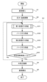
- FIG. 5 is a flow diagram showing details of the first process gas supply step in FIG.
- FIG. 6 is a conceptual diagram of the inside of the tank in the first process gas supply step of FIG.
- the substrate processing apparatus 10 includes a reaction tube storage chamber 206b, which includes a cylindrical reaction tube 210 extending vertically, a heater 211 as a heating section (furnace body) installed on the outer periphery of the reaction tube 210, a gas supply structure 212 as a gas supply section, and a gas exhaust structure 213 as a gas exhaust section.
- the gas supply section may include an upstream straightening section 214 and nozzles 223 and 224, which will be described later.
- the gas exhaust section may include a downstream straightening section 215, which will be described later.
- the processing chamber 201 can also be called a processing space in which the substrate S is placed.
- the gas supply structure 212 is provided upstream of the reaction tube 210 in the gas flow direction, and gas is supplied from the gas supply structure 212 into the reaction tube 210, and the gas is supplied horizontally to the substrate S.
- the gas exhaust structure 213 is provided downstream of the reaction tube 210 in the gas flow direction, and the gas inside the reaction tube 210 is exhausted from the gas exhaust structure 213.
- the gas supply structure 212, the inside of the reaction tube 210, and the gas exhaust structure 213 are horizontally connected.
- An upstream straightening section 214 that straightens the flow of gas supplied from the gas supply structure 212 is provided on the upstream side of the reaction tube 210 between the reaction tube 210 and the gas supply structure 212.
- a downstream straightening section 215 that straightens the flow of gas exhausted from the reaction tube 210 is provided on the downstream side of the reaction tube 210 between the reaction tube 210 and the gas exhaust structure 213.
- the lower end of the reaction tube 210 is supported by a manifold 216.
- the reaction tube 210, the upstream rectifier 214, and the downstream rectifier 215 are continuous structures and are made of materials such as quartz or SiC. These are made of heat-transmitting materials that transmit the heat radiated from the heater 211. The heat from the heater 211 heats the substrate S and the gas.
- Gas supply structure 212 has gas supply pipes 251 and 261 connected thereto, and also has a distribution section 225 that distributes the gas supplied from each gas supply pipe.
- a plurality of nozzles 223 and 224 are provided downstream of distribution section 225.
- Gas supply pipe 251 and gas supply pipe 261 supply different types of gas as described below.
- Nozzles 223 and 224 are arranged in an up-down relationship or a side-by-side relationship.
- gas supply pipe 251 and gas supply pipe 261 are also collectively referred to as gas supply pipe 221.
- Each nozzle is also referred to as a gas discharge section.
- Distribution section 225 is configured so that gas is supplied from gas supply pipe 251 to nozzle 223, and from gas supply pipe 261 to nozzle 224.
- the upstream straightening section 214 has a housing 227 and a partition plate 226.
- the partition plate 226 extends horizontally and has a continuous structure without holes.
- the horizontal direction here refers to the side wall direction of the housing 227.
- Multiple partition plates 226 are arranged in the vertical direction.
- the partition plates 226 are fixed to the side wall of the housing 227 and are configured so that gas does not move beyond the partition plate 226 downward or upward into adjacent areas.
- Each partition plate 226 is provided at a position corresponding to each substrate S.
- Nozzles 223 and 224 are provided between the partition plates 226 and between the partition plates 226 and the housing 227.
- the gas discharged from the nozzles 223 and 224 has its flow adjusted by the partition plate 226 and is supplied to the surface of the substrate S. In other words, when viewed from the substrate S, the gas is supplied from the lateral direction of the substrate S.
- the downstream straightening section 215 is configured so that when the substrate S is supported on the substrate support 300, the ceiling is higher than the substrate S arranged at the top, and the bottom is lower than the substrate S arranged at the bottom of the substrate support 300.
- the downstream straightening section 215 has a housing 231 and a partition plate 232.
- the partition plate 232 extends horizontally and has a continuous structure without holes.
- the horizontal direction here refers to the side wall direction of the housing 231.
- multiple partition plates 232 are arranged in the vertical direction.
- the partition plate 232 is fixed to the side wall of the housing 231 and is configured so that gas does not move beyond the partition plate 232 downward or upward into adjacent areas.
- the partition plates 232 are provided at positions corresponding to the substrates S, respectively, at positions corresponding to the partition plates 226. It is desirable that the corresponding partition plates 226 and 232 are of the same height. Furthermore, when processing the substrates S, it is desirable to align the height of the substrates S with the heights of the partition plates 226 and 232. This suppresses vertical flow from the partition plate 226, over the substrates S, and the partition plate 232, and makes the difference in gas pressure over each substrate S uniform. Therefore, each substrate S can be processed uniformly.
- the pressure loss in the vertical direction can be made uniform upstream and downstream of each substrate S.
- a horizontal gas flow can be reliably formed in which the vertical flow is suppressed from the partition plate 226, over the substrate S, to the partition plate 232. Therefore, the difference in gas pressure on each substrate S can be reduced. This allows each substrate S to be processed uniformly.
- the gas exhaust structure 213 is provided downstream of the downstream straightening section 215.
- the gas exhaust structure 213 is mainly composed of a housing 241 and an exhaust pipe connection section 242.
- the housings 231 and 241 have a structure in which the heights of their ceilings and bottoms are continuous.
- An exhaust hole 244 is formed on the downstream side of the housing 241, below or horizontally, for exhausting gas that has passed through the downstream straightening section 215.
- the gas exhaust structure 213 is provided laterally of the reaction tube 210, and is a lateral exhaust structure that exhausts gas from the lateral direction of the substrate S.
- the transfer chamber 217 is installed at the bottom of the reaction tube 210 via a manifold 216.
- a vacuum transfer robot places (mounts) the substrate S on a substrate support (hereinafter, sometimes simply referred to as a boat) 300 via a substrate entrance, and the vacuum transfer robot removes (loads) the substrate S from the substrate support 300.
- a substrate support hereinafter, sometimes simply referred to as a boat
- the inside of the transfer chamber 217 can store the substrate support 300, the partition plate support 310, and the vertical drive mechanism 400 that drives the substrate support 300 and the partition plate support 310 (collectively referred to as the substrate holder) in the vertical and rotational directions.
- the substrate support 300 is shown raised by the vertical drive mechanism 400 and stored in the reaction tube 210.
- the vertical drive mechanism 400 includes a rotary drive mechanism 430 that rotates the substrate support 300 and the partition support 310 together, and a boat vertical mechanism 420 that drives the substrate support 300 vertically relative to the partition support 310.
- the rotary drive mechanism 430 and the boat vertical mechanism 420 are fixed to a base flange 401 that serves as a lid supported by a side plate 403 on a base plate 402.
- An O-ring 446 for vacuum sealing is installed on the upper surface of the base flange 401.
- the inside of the reaction tube 210 can be kept airtight by being driven by the vertical drive motor 410 to raise the base flange 401 to a position where the upper surface of the base flange 401 is pressed against the transfer chamber 217.
- the support 440 and the support 441 fixed to the substrate support 300 are connected by a vacuum bellows 443.
- the substrate support section is composed of at least a substrate support 300 that supports a substrate S, and is stored inside the reaction tube 210.
- the substrate support section transfers the substrate S using a vacuum transport robot through a substrate loading port (not shown) inside the transfer chamber 217, and transports the transferred substrate S into the reaction tube 210 to perform processing to form a thin film on the surface of the substrate S.
- the substrate loading port is provided, for example, on a side wall of the transfer chamber 217.
- the substrate support section may also include a partition plate support section 310.
- the partition plate 314 is placed directly below the substrate S and either above or below the substrate S or both.
- the partition plate 314 blocks the space between each substrate S.
- the predetermined interval between the multiple substrates S placed on the substrate support 300 is the same as the vertical interval between the partition plates 314 fixed to the partition plate support portion 310.
- the diameter of the partition plate 314 is formed to be larger than the diameter of the substrate S.
- the substrate support 300 may be configured to be able to support approximately 5 to 50 substrates S.
- the partition plate 314 is also called a separator. Note that in this specification, a numerical range such as "5 to 50 sheets” means that the lower limit and upper limit are included in the range. Thus, for example, "5 to 50 sheets” means “5 sheets or more and 50 sheets or less.” The same applies to other numerical ranges.
- the gas supply pipe 251 is provided with, in order from the upstream direction, a first process gas source 252, a mass flow controller (MFC) 253 which is a flow rate controller (flow rate control section), a valve 275 which is an on-off valve, a tank 259 which is a storage section that stores gas therein, a pressure sensor 301 which is a pressure gauge (pressure measurement section) that measures the pressure inside the tank 259, and a valve 254.
- the pressure sensor 301 can be regarded as an example of a measurement section that measures the amount of gas in the tank 259, or a detection section that detects that the amount of gas in the tank 259 has reached a specific amount.
- the first processing gas source 252 is a gas source for supplying a first processing gas as a processing gas.
- the first processing gas is a raw material gas and is one of the processing gases.
- a vaporizer or the like may also be used as the first processing gas source 252.
- the first processing gas supply system 250 (also called a raw material gas supply system) is mainly composed of the gas supply pipe 251, the MFC 253, the valve 275, the tank 259, the pressure sensor 301, and the valve 254.
- the first processing gas source 252 may be included in the first processing gas supply system 250.
- a gas exhaust pipe 302 is connected to the gas supply pipe 251 between the pressure sensor 301 and the valve 254, for discharging the gas in the tank 259 outside the processing chamber 201 without supplying it to the processing chamber 201.
- a valve 303 is provided on the gas exhaust pipe 302.
- the gas exhaust pipe 302 and the valve 303 mainly constitute a first processing gas exhaust system (also called a raw material gas exhaust system).
- the first processing gas exhaust system may be included in the first processing gas supply system 250.
- a gas supply pipe 255 is connected between the valve 275 and the tank 259 of the gas supply pipe 251.
- An inert gas source 256, an MFC 257, and a valve 258 are provided in the gas supply pipe 255, in that order from the upstream direction.
- An inert gas is supplied from the inert gas source 256.
- a first inert gas supply system is mainly constituted by the gas supply pipe 255, the MFC 257, and the valve 258.
- the inert gas supplied from the inert gas source 256 acts as a purge gas that purges gas remaining in the reaction tube 210.
- the inert gas source 256 may be included in the first inert gas supply system.
- the first inert gas supply system may be included in the first processing gas supply system 250.
- the gas supply pipe 261 is provided with, in order from the upstream direction, a second process gas source 262, an MFC 263, and a valve 264.
- the second process gas source 262 is a gas source for supplying a second process gas as a process gas.
- the second process gas is a reactive gas or a modifying gas that reacts with the raw material gas, and is one of the process gases.
- the second process gas supply system 260 (also called a reactive gas supply system) is mainly composed of the gas supply pipe 261, the MFC 263, and the valve 264.
- the second process gas source 262 may be included in the second process gas supply system 260.
- a gas supply pipe 265 is connected to the gas supply pipe 261 downstream of the valve 264.
- An inert gas source 266, an MFC 267, and a valve 268 are provided in the gas supply pipe 265, in that order from the upstream direction.
- An inert gas is supplied from the inert gas source 266.
- a second inert gas supply system is mainly constituted by the gas supply pipe 265, the MFC 267, and the valve 268.
- the inert gas supplied from the inert gas source 266 acts as a purge gas that purges gas remaining in the reaction tube 210.
- the inert gas source 266 may be included in the second inert gas supply system.
- the second inert gas supply system may be included in the second processing gas supply system 260.
- An exhaust system 280 for exhausting the atmosphere in the reaction tube 210 has an exhaust pipe 281 communicating with the reaction tube 210 , and is connected to the housing 241 via an exhaust pipe connection part 242 .
- a vacuum pump 284 serving as a vacuum exhaust device is connected to the exhaust pipe 281 via a valve 282 and an APC (Auto Pressure Controller) valve 283 serving as a pressure regulator (pressure adjustment unit), and is configured to be able to evacuate the reaction tube 210 to a predetermined pressure (vacuum level).
- the exhaust pipe 281, valve 282, and APC valve 283 are collectively referred to as the exhaust system 280.
- the exhaust system 280 is also referred to as the processing chamber exhaust system.
- the exhaust system 280 may also include the vacuum pump 284.
- the substrate processing apparatus 10 has a controller 600 that controls the operation of each part of the substrate processing apparatus 10.
- the controller 600 is shown in outline in FIG. 3.
- the controller 600 is configured as a computer equipped with a CPU (Central Processing Unit) 601, a RAM (Random Access Memory) 602, a storage device 603 as a storage unit, and an I/O port 604.
- the RAM 602, the storage device 603, and the I/O port 604 are configured to be able to exchange data with the CPU 601 via an internal bus 605.
- the storage device 603 is composed of, for example, a flash memory, a hard disk drive (HDD), etc.
- a control program that controls the operation of the substrate processing device 10, a process recipe that describes the procedures and conditions for substrate processing, etc. are stored in a readable manner in the storage device 603.
- the process recipe functions as a program, which is a combination of steps in the substrate processing process described below that are executed by the controller 600 to obtain a predetermined result.
- the process recipe and control program are collectively referred to as simply a program.
- the word program may include only the process recipe, only the control program, or both.
- the RAM 602 is configured as a memory area (work area) in which programs and data read by the CPU 601 are temporarily stored.
- the I/O port 604 is connected to the above-mentioned vertical drive mechanism 400, heater 211, APC valve 283, vacuum pump 284, MFCs 253, 257, 263, 267, valves 254, 258, 264, 268, 275, 282, 303, pressure sensor 301, rotation drive mechanism 430, etc.
- the CPU 601 is configured to read and execute a control program from the storage device 603, and to read a process recipe from the storage device 603 in response to input of an operation command from the input/output device 681, etc.
- the CPU 601 is then configured to control the raising and lowering of the substrate support 300 by the vertical drive mechanism 400, the heating by the heater 211, the opening and closing of the APC valve 283, the start and stop of the vacuum pump 284, the flow rate adjustment of various gases by the MFCs 253, 257, 263, 267, the opening and closing of the valves 254, 258, 264, 268, 275, 282, 303, the pressure measurement in the tank 259 by the pressure sensor 301, the rotation of the substrate support 300 and the rotation speed adjustment by the rotation drive mechanism 430, etc., in accordance with the contents of the read process recipe.
- MFCs 253, 257, 263, 267, valves 254, 258, 264, 268, 275, 282, 303, APC valve 283, and vacuum pump 284 can be used as a gas control unit configured to control the supply and exhaust of gas into processing chamber 201.
- the controller 600 can be configured by installing the program in the computer using an external storage device (e.g., a magnetic disk such as a hard disk, an optical disk such as a DVD, a magneto-optical disk such as an MO, or a semiconductor memory such as a USB memory) 682 that stores the above-mentioned program.
- the means for supplying the program to the computer is not limited to supplying it via the external storage device 682.
- the program may be supplied without going through the external storage device 682 by using a communication means such as the Internet or a dedicated line.
- the storage device 603 and the external storage device 682 are configured as computer-readable recording media on which the program is recorded. Hereinafter, these are collectively referred to simply as recording media. In this specification, when the term recording medium is used, it may include only the storage device 603 alone, only the external storage device 682 alone, or both.
- substrate used in this specification can mean the substrate itself, or a laminate of the substrate and a specified layer or film formed on its surface.
- surface of the substrate used in this specification can mean the surface of the substrate itself, or the surface of a specified layer, etc. formed on the substrate.
- Substrate loading step S1 A plurality of substrates S are loaded (wafer charge) onto the substrate support 300 in the transfer chamber 217. Then, the substrate support 300 supporting the substrates S is raised by the vertical drive mechanism 400, and the substrates S are carried into the reaction tube 210 (boat load), and the lower end of the reaction tube 210 is sealed by the base flange 401 via an O-ring 446. At this time, the surface of the substrate S is positioned so as to be flush with the height of the partition plates 226 and 232.
- membrane treatment process S4 is performed by performing the first treatment gas supply process S41, the purge gas supply process S42, the second treatment gas supply process S43, and the purge gas supply process S44 a predetermined number of times (n times, n is an integer of 1 or 2 or more).
- flush supply refers to supplying a large flow rate of gas into the reaction tube 210 in a short period of time.
- the first process gas supply step S41 is performed by performing the next storage step S411 and supply step S412 a predetermined number of times (p times, where p is an integer of 1 or 2 or more).
- FIG. 7 is a flow diagram showing the details of the first process gas supply step S41
- FIG. 8 is an image diagram for explaining the first process gas supply step S41.
- the amount of the first process gas stored in the tank 259 is represented typically by the height of a gray rectangle in the tank 259. Also, FIG.
- FIG. 8 shows, from the left, the amount of the first process gas stored in the tank 259 at the start of the storage step S411, the end of the storage step S411 and the start of the supply step S411, the end of the supply step S411 and the start of the storage step S411, and the end of the storage step S411 and the start of the supply step S411.
- a predetermined amount X or more of the first process gas is stored in the tank 259.
- valve 275 is opened while valves 254, 258, 303, 264, and 268 are closed, and when a predetermined time has elapsed, valve 275 is closed.
- the first process gas whose flow rate is adjusted by MFC 253 is filled into tank 259 in which the first process gas is stored to a predetermined amount X or more, and when the predetermined time has elapsed, valve 275 is closed.
- the flow rate of the first process gas supplied to the tank 259 and/or the time for which the first process gas is continuously supplied to the tank 259 are controlled according to the remaining amount of the first process gas in the tank 259. That is, the amount of the first process gas stored in the tank 259 in this step can be changed in each cycle of the first process gas supply process S41.
- the stored flow rate the flow rate of the first process gas supplied to the tank 259
- the storage time the time for which the first process gas is continuously supplied to the tank 259
- the amount of the first process gas stored in the tank 259 at the start of the supply process S412 can be kept constant between cycles.
- either the storage flow rate or the storage time may be kept constant over multiple cycles, and the other may be changed at least once during the multiple cycles. That is, the storage flow rate may be controlled by the MFC 253 according to the remaining amount of the first processing gas in the tank 259 at the end of the supply process S412, or the storage time may be controlled by opening and closing the valve 275, or both the storage flow rate by the MFC 253 and the storage time by opening and closing the valve 275 may be controlled.
- the storage flow rate constant over multiple cycles and changing the storage time at least once during the multiple cycles, it becomes easier to control the amount of the first processing gas stored in the tank 259 even when the pressure inside the tank 259 is high.
- By keeping the storage time constant over multiple cycles and changing the storage flow rate at least once during the multiple cycles it is possible to reduce the processing variation between lots that accompanies the change in storage time.
- the first process gas stored in the tank 259 is flush-supplied to the substrate S. That is, the valve 254 is opened while the valves 258, 275, 303, 264, and 268 are closed, and after a predetermined time has elapsed, At this time, the valve 254 is closed. At this time, the high-pressure first process gas stored in the tank 259 is supplied to the substrate S through the gas supply pipe 251 at once.
- the first process gas is The gas is supplied in large quantities from the supply structure 212 through the upstream rectifier 214 into the reaction tube 210 in a short time, and then is exposed to the space above the substrate S, the downstream rectifier 215, the gas exhaust structure 213, The air is exhausted through an exhaust pipe 281. At this time, a valve 282 and an APC valve 283 are in an open state.
- valve 254 is closed when the amount of first process gas in tank 259 reaches target amount Z, which is equal to or greater than the predetermined amount X.
- the predetermined amount X can be set to any value between 0.1 and 99% of the amount of first process gas (predetermined amount Y) stored in tank 259 at the start of supply process S412.
- the predetermined amount X when the predetermined amount X is set to 10 to 90% of the predetermined amount Y, the step coverage and the film formation rate can be easily controlled to the desired values. If it is less than 10%, the step coverage may decrease due to the first processing gas being supplied to the substrate S at a low flow rate. In addition, as described below, the temperature of the first processing gas may decrease significantly due to the first processing gas undergoing an assumption close to adiabatic expansion, and the film formation rate may decrease. If it exceeds 90%, the film formation rate may decrease due to the decrease in the amount of the first processing gas supplied to the substrate S.
- the first process gas can be flush-supplied to the substrate S under the desired conditions.
- the first process gas can be flush-supplied so that at least one of the flow rate, residence time, decomposition rate, and partial pressure in the process chamber 201 is within a desired range.
- the flow rate of the first process gas can be made to be equal to or greater than a predetermined flow rate in this step, and the residence time of the first process gas in the process chamber 201 can be shortened.
- the predetermined amount X to remain in the tank 259 at the end of this step is set so that the decomposition rate of the first process gas in the process chamber 201, which is the space in which the substrate S exists in this step, is equal to or lower than the predetermined decomposition rate. If the decomposition rate of the first process gas supplied to the substrate S becomes higher than the predetermined decomposition rate, the step coverage may be easily reduced. By preventing the decomposition rate of the first process gas supplied to the substrate S from becoming higher than the predetermined decomposition rate, the step coverage can be improved.
- the predetermined amount X is set so that the flow rate of the first process gas in the process chamber 201 in this step is equal to or greater than the predetermined flow rate. This makes it possible to prevent the decomposition rate of the first process gas supplied to the substrate S from becoming higher than the predetermined decomposition rate. This makes it possible to improve the step coverage.
- reaction by-products such as hydrogen chloride (HCl) that inhibit the adsorption of the first process gas to the substrate surface may be generated. Therefore, at least some of the adsorption sites on the surface of the substrate S are adsorbed with elements contained in the first process gas, but reaction by-products such as HCl are adsorbed to the adsorption sites on the substrate S and inhibit the adsorption of elements contained in the first process gas.
- HCl hydrogen chloride
- the flow rate of the first process gas in the process chamber 201 is set to be equal to or higher than a predetermined flow rate, and the first process gas is flush-supplied, so that a large amount of the first process gas is supplied to the substrate S in a short time after the start of supply, thereby reducing the adsorption sites on the substrate S for the reaction by-products and increasing the amount of adsorption of elements contained in the first process gas. This makes it possible to improve the step coverage performance while improving the film formation rate.
- the flow velocity of the first process gas refers to a number that is an index of the distance that the first process gas supplied into the process chamber 201 travels per unit time. It may also be a number that is an index of the distance that the first process gas travels per unit time in the process chamber 201. It may also be a number that is an index of the distance that the gas travels per unit time in the process space.
- the flow velocity of the first process gas may also be the average flow velocity of the first process gas on the substrate S.
- the flow velocity of the first process gas may also be the average flow velocity from one location (or region) to another location (or region), such as the average flow velocity from when the first process gas is discharged from a gas supply unit such as the nozzle 223 into the process chamber 201 to when it reaches the exhaust hole 244.
- the average flow velocity of the first process gas in the process space may also be used.
- the average flow velocity of the first process gas in the process chamber 201 may also be used.
- the flow velocity of the first processing gas at a certain point on the substrate S, or in the processing space, or in the processing chamber 201 may be used.
- the residence time of the first process gas in the process chamber 201 is equal to or less than the predetermined residence time. That is, the predetermined amount X may be set so that the residence time of the first process gas in the space in which the substrate S exists in this step is equal to or less than the predetermined residence time. This makes it possible to prevent the decomposition rate of the first process gas supplied to the substrate S from becoming higher than the predetermined decomposition rate.
- the residence time of the first process gas described above can be set to be equal to or less than a predetermined residence time and/or the flow rate of the first process gas can be set to be equal to or greater than a predetermined flow rate, thereby reducing the decomposition rate of the first process gas and improving and enhancing step coverage.
- the residence time of the first process gas refers to a number that is an index of the time until the first process gas supplied into the process chamber 201 is exhausted from the process chamber 201. It may also be a number that is an index of the time until the gas that has reached the process space leaves the process space.
- the residence time of the first process gas may also be the time until the first process gas that has reached the substrate S leaves the substrate S.
- the residence time of the first process gas may be, for example, the time until the first process gas that has reached the process space escapes from the process space.
- the time from when the first process gas is discharged from a gas supply unit such as the nozzle 223 until it reaches the exhaust hole 244 may also be used.
- the time from when the supply of the first process gas starts to when the supply of the first process gas ends may also be used, for example, the time from when a certain component of the substrate processing apparatus 10 starts or ends a certain operation, such as the time from when the valve 254 downstream of the tank 259 is opened to when the valve 254 is closed.
- the predetermined amount X may be set so that the partial pressure of the first process gas in the space in which the substrate S exists in this step is equal to or greater than the predetermined partial pressure. This allows the first process gas to reach the deeper parts of the recesses more easily, improving step coverage. Furthermore, the probability of the first process gas colliding with the surface of the substrate S per unit time and unit area increases. This makes it possible to improve the film formation rate, which is the film thickness formed on the surface of the substrate S per unit time.
- the predetermined amount X may be set so that the temperature inside the tank 259 (e.g., the temperature of the tank 259 itself, or the temperature of the first process gas inside the tank 259) is equal to or higher than a predetermined temperature in this step. This can improve the film formation rate.
- the first process gas in the tank 259 expands in a short time.
- the temperature of the first process gas released from the tank 259 drops, and the temperatures in the tank 259, the substrate S, and the process chamber 201 also drop accordingly.
- the reaction between the substrate and the first process gas and/or the second process gas becomes less likely to proceed (the reactivity of the first process gas and/or the second process gas decreases), which may result in a decrease in the film formation rate.
- the predetermined amount X may also be set so that the first processing gas present in the tank 259 does not liquefy or solidify in this step. This makes it possible to suppress the generation of particles.
- the first process gas filled in the tank 259 When the first process gas filled in the tank 259 is supplied from the tank 259 to the process chamber 201, the first process gas is supplied to the substrate S through a process close to adiabatic expansion, which reduces the temperature of the first process gas and the tank 259. At the same time, the pressure inside the tank 259 also reduces. As a result, the temperature and pressure inside the tank 259 may reach a level at which the first process gas liquefies or solidifies. The liquefied or solidified first process gas may cause particle generation.
- the amount of the first process gas in the tank 259 at the end of the supply process S412 can be set so that the first process gas in the tank 259 does not liquefy or solidify between the start and end of the supply process S412.
- the technology disclosed herein can be suitably applied even when a process gas obtained by vaporizing a liquid or solid substance at room temperature and normal pressure is flash-supplied.
- valve 258 may be opened to supply an inert gas into gas supply pipe 251 via gas supply pipe 255. Also, in order to prevent the first process gas from entering gas supply pipe 261, valves 268 and 264 may be opened to supply an inert gas into gas supply pipe 261.
- Predetermined number of times execution S413 The cycle of the above-described storing step S411 and supplying step S412 is repeated a predetermined number of times (p times, where p is an integer of 1 or 2 or more), thereby forming a first layer having a desired thickness.
- the first processing gas stored in the tank 259 is supplied to the processing chamber 201 while expanding in a process close to adiabatic expansion. Therefore, the flash supply reduces the temperature of the first processing gas and the temperature of the first processing gas supply system 250 including the tank 259.
- the technology disclosed herein can control the magnitude of the pressure drop in the tank 259 by the amount of the first processing gas in the tank 259 at the end of the flash supply. Therefore, the technology disclosed herein can control the magnitude of the temperature drop in the tank 259 due to the adiabatic expansion of the first processing gas associated with the flash supply.
- the amount of the first process gas in the tank 259 may be controlled by the pressure in the tank 259. That is, the amount of the first process gas in the tank 259 may be controlled by the pressure in the tank 259 measured by the pressure sensor 301.
- the control of the pressure in the tank 259 can be considered as the control of the amount of the first process gas in the tank 259. Therefore, the supply process S412 can be considered to have ended after the measurement unit (e.g., the pressure sensor 301) detects that the amount of gas in the tank 259 is equal to or greater than a predetermined amount.
- the supply process S412 may be performed so that the pressure in the tank 259 at the end of the supply process S412 is equal to or greater than a predetermined pressure. Even in this case, the decomposition rate of the first process gas supplied to the substrate S can be prevented from becoming higher than the predetermined decomposition rate.
- the predetermined pressure can be set to any value between 0.1 and 99% of the pressure in the tank 259 at the start of the supply process S412.
- the step coverage and the film formation rate can be easily controlled to preferred values. If it is less than 10%, the step coverage may decrease due to the first processing gas being supplied to the substrate S at a low flow rate. In addition, as described below, the temperature of the first processing gas may decrease significantly due to the first processing gas undergoing an assumption close to adiabatic expansion, and the film formation rate may decrease. If it exceeds 90%, the amount of the first processing gas supplied to the substrate S may decrease, and the film formation rate may decrease.
- the specified pressure it is preferable to set the specified pressure to 20 to 85% of the pressure in the tank 259 at the end of the supply process S412, as this makes it even easier to control the step coverage and the film formation rate to preferred values. Furthermore, it is even more preferable to set the specified pressure to 30 to 80% of the pressure in the tank 259 at the end of the supply process S412, as this makes it much easier to control the step coverage and film formation rate.
- a purge gas is supplied to the processing chamber 201 in which the substrate S is disposed. That is, after a first layer is formed on the substrate S, the valves 275, 303, 264 are closed and the valves 254, 258, 268 are opened to supply an inert gas as a purge gas into the gas supply pipes 251, 261 via the gas supply pipes 255, 265, and the valve 282 and the APC valve 283 of the exhaust pipe 281 are kept open, and the processing chamber 201 is evacuated to a vacuum by the vacuum pump 284, and the processing chamber 201 is purged.
- valve 264 is opened while the valves 254, 258, 275, 303, and 268 are closed, and the valve 264 is closed when a predetermined time has elapsed.
- the second process gas whose flow rate is adjusted by the MFC 263 is supplied to the substrate S through the gas supply pipe 261.
- the second process gas is supplied from the gas supply structure 212 through the upstream rectifier 214 into the reaction tube 210, and then exposed and exhausted through the space above the substrate S, the downstream rectifier 215, the gas exhaust structure 213, and the exhaust pipe 281.
- the valve 282 and the APC valve 283 are in an open state.
- valve 268 may be opened to flow an inert gas into the gas supply pipe 261 through the gas supply pipe 265.
- the valves 258 and 254 may be opened to flow an inert gas into the gas supply pipe 251. This allows the first layer on the substrate S to be modified into the second layer.
- a purge gas is supplied to the processing chamber 201 in which the substrate S is placed by the same processing procedure as in the above-mentioned purge gas supply step S42. That is, after the first layer on the substrate S is modified to the second layer, the valves 254, 258, 268 are opened while the valves 275, 303, 264 are closed, and an inert gas is supplied as a purge gas into the gas supply pipes 251, 261 through the gas supply pipes 255, 265, and the inside of the processing chamber 201 is evacuated to a vacuum by the vacuum pump 284 while the valve 282 and the APC valve 283 of the exhaust pipe 281 are kept open, and the inside of the processing chamber 201 is purged.
- Predetermined number of times S45 The cycle of the above-mentioned first process gas supply step S41, purge gas supply step S42, second process gas supply step S43, and purge gas supply step S44 is performed a predetermined number of times (n times, n is an integer of 1 or 2 or more).
- n times, n is an integer of 1 or 2 or more.
- an inert gas is supplied into the processing chamber 201 and exhausted from the exhaust pipe 281.
- the inert gas acts as a purge gas, and thereby the processing chamber 201 is purged with the inert gas, and gas and reaction by-products remaining in the processing chamber 201 are removed from the processing chamber 201. Thereafter, the atmosphere in the processing chamber 201 is replaced with the inert gas, and the pressure in the processing chamber 201 is returned to normal pressure (return to atmospheric pressure).
- Substrate unloading process S6 The base flange 401 is lowered by the vertical drive mechanism 400, and the lower end of the reaction tube 210 is opened. Then, the processed substrate S is carried out ( The processed substrate S is removed from the substrate support 300 in the transfer chamber 217 (wafer discharge).
- the time from the start of the supply step S412 of the first process gas supply step S41 to the time when the amount of the first process gas in the tank 259 becomes a predetermined amount X is obtained using a predetermined method. Then, the data obtained by this process is used in the above-mentioned substrate processing process.
- the predetermined method for example, data acquisition from substrate processing or experiments performed in advance, prediction based on such data, numerical calculation including analysis by computational fluid dynamics (CFD), machine learning, deep learning, etc. are used.
- CFD computational fluid dynamics
- the current amount of the first process gas in the tank 259 is determined based on the pressure in the tank 259 measured by the pressure sensor 301.
- the valve 275, MFC 253, etc. are controlled so that the supply process S412 ends before the time acquired by the pre-evaluation process has elapsed from the start of the supply process S412, or when the time acquired by the pre-evaluation process has elapsed.
- the control by the controller 600 can be simplified.
- the gas flow is described as horizontal, but it is sufficient that the main gas flow is formed in a horizontal direction overall, and the gas flow may be diffused vertically as long as it does not affect the uniform processing of multiple substrates.
- the above uses expressions such as "to the same extent,” “equivalent,” and “equal,” but it goes without saying that these include essentially the same thing.
- a raw material gas is used as the first processing gas, and a reactive gas is used as the second processing gas.
- a reactive gas may be used as the first processing gas
- a raw material gas may be used as the second processing gas.
- a cycle in which the second processing gas supply process is followed by the first processing gas supply process may be performed a predetermined number of times. That is, the raw material gas may be flush-supplied and then the reactive gas may be supplied, or the raw material gas may be supplied and then the reactive gas may be flush-supplied.
- both the raw material gas and the reactive gas may be flush-supplied. That is, the raw material gas may be flush-supplied and then the reactive gas may be flush-supplied.
- a gas containing a specific element such as tungsten (W), titanium (Ti), molybdenum (Mo), tantalum (Ta), cobalt (Co), yttrium (Y), ruthenium (Ru), hafnium (Hf), zirconium (Zr), aluminum (Al), silicon (Si), etc.
- a gas excited by plasma or the like of these gases can also be used.
- a halogen-based predetermined element-containing gas containing a predetermined element and a halogen element can be used.
- halogen-based predetermined element-containing gases include tungsten hexachloro (WCl 6 ), tungsten hexafluoro (WF 6 ), titanium tetrachloride (TiCl 4 ), titanium tetrafluoride (TiF 4 ), molybdenum pentachloride (MoCl 5 ), molybdenum pentafluoride (MoF 5 ), molybdenum dioxide dichloride (MoO 2 Cl 2 ), molybdenum oxide tetrachloride (MoOCl 4 ), tantalum pentachloride (TaCl 5 ), tantalum pentafluoride (TaF 5 ), cobalt difluoride (CoF 2 ), cobalt dichloride (CoCl 2 ), yt
- the predetermined element-containing gas may be, for example, a gas containing monosilane (SiH 4 ), disilane (Si 2 H 6 ), trisilane (Si 3 H 8 ), tetrasilane (Si 4 H 10 ), etc. One or more of these may be used as the predetermined element-containing gas.
- an organic predetermined element-containing gas having a predetermined element and an organic ligand can be used as the predetermined element-containing gas.
- trisdimethylaminocyclopentadienyl hafnium ((Cp)Hf[N(Me) 2 ] 3 ), tetrakisethylmethylamino zirconium (Zr[N(Me)Cp] 4 ), tetrakisdiethylamino zirconium (Zr[N(Et) 2 ] 4 ), tetrakisdimethylamino zirconium (Zr[N(Me) 2 ] 4 ), trisdimethylaminocyclopentadienyl zirconium ((Cp)Zr[N(Me) 2 ] 3 ), trimethylaluminum (Al( CH3 ) 3 ), trisdimethylaminosilane (Si[N( CH3 ) 2 ] 3H ), or the like can be used as the predetermined element-containing gas. One or more of these can be used as the predetermined element-containing gas.
- the reactive gas may be, for example, a gas containing a reducing gas, an oxidizing gas, a nitriding gas, a sulfide gas, a selenide gas, a telluride gas, or the like.
- a gas excited by plasma or the like of these gases may also be used as the reactive gas.
- one of the first and second processing gases is a gas containing a specific element and the other is a reducing gas, a film composed of a single specific element can be formed on the substrate S.
- one of the first and second processing gases is a gas containing a specific element and the other is any one of an oxidizing gas, a nitriding gas, a sulfide gas, a selenide gas, or a telluride gas
- an oxide film of a specific element, a nitride film of a specific element, a sulfide film of a specific element, a selenide film of a specific element, or a telluride film of a specific element can be formed on the wafer.
- the reducing gas may be, for example, one or more of hydrogen (H 2 ) gas, deuterium (D 2 ) gas, borane (BH 3 ) gas, diborane (B 2 H 6 ) gas, carbon monoxide (CO) gas, ammonia (NH 3 ) gas, monosilane (SiH 4 ) gas, disilane (Si 2 H 6 ) gas, trisilane (Si 3 H 8 ) gas, monogermane (GeH 4 ) gas, digermane (Ge 2 H 6 ), etc.
- the reactive gas may be, for example, an oxidizing gas containing oxygen (O).
- the oxidizing gas may be, for example, one or more of gases containing oxygen (O 2 ), ozone (O 3 ), water vapor (H 2 O), a mixed gas of H 2 and O 2 , hydrogen peroxide (H 2 O 2 ), nitrous oxide (N 2 O), etc.
- oxygen O 2
- ozone O 3
- water vapor H 2 O
- hydrogen peroxide H 2 O 2
- nitrous oxide N 2 O
- the nitriding gas for example, one or more of hydrogen nitride gases such as ammonia (NH 3 ) gas, diazene (N 2 H 2 ) gas, hydrazine (N 2 H 4 ) gas, and N 3 H 8 gas can be used.
- NH 3 ammonia
- N 2 H 2 diazene
- N 2 H 4 hydrazine
- N 3 H 8 gas N 3 H 8 gas
- sulfurizing gas for example, a gas containing sulfane (H 2 S), disulfane (H 2 S 2 ), diammonium sulfide ((NH 4 ) 2 S), dimethyl sulfide ((CH 3 ) 2 S), etc. can be used.
- sulfurizing gas for example, one or more of these can be used.
- selenizing gas for example, a gas containing selenium (H 2 Se), diselane (H 2 Se 2 ), dimethylselenium ((CH 3 ) 2 Se), etc. can be used.
- selenizing gas for example, one or more of these can be used.
- the tellurization gas may be, for example, a gas containing tellurane (H 2 Te), diterane (H 2 Te 2 ), dimethylselenium ((CH 3 ) 2 Te), etc. One or more of these may be used as the tellurization gas.
- the inert gas for example, rare gases such as helium (He), argon (Ar), neon (Ne) gas, xenon (Xe) gas, nitrogen (N 2 ), etc. can be used.
- rare gases such as helium (He), argon (Ar), neon (Ne) gas, xenon (Xe) gas, nitrogen (N 2 ), etc.
- the inert gas one or more of these can be used.
- the first process gas is flush-supplied using one tank 259, but the present embodiment is not limited to this. That is, the first process gas may be flush-supplied to the substrate S using multiple tanks. By using multiple tanks, while the first process gas is stored in one tank, the first process gas can be flush-supplied from the other tank. In this embodiment, the same effect as the above embodiment can be obtained. In addition, in this embodiment, the throughput can be further improved. In addition, the first process gas may be flush-supplied to the substrate S at least partially from multiple tanks at the same time. In this embodiment, the same effect as the above embodiment can be obtained. In addition, in this embodiment, the flow rate of the first process gas in the processing chamber 201 can be further increased. This makes it easier to improve the step coverage.
- the flush supply of the first process gas to the substrate S from the two or more tanks 259 may be performed at least partially simultaneously.
- the same effects as in the embodiment described above can be obtained.
- the amount of the first process gas supplied from each tank can be further reduced. This makes it easier to supply a sufficient amount of the first process gas even when the predetermined amount X is set to a large amount. Therefore, it becomes easier to further improve the step coverage.
- first processing gas supply system 250 is described using a case where the tank 259 is provided, this embodiment is not limited to this. That is, the second processing gas supply system 260 may be provided with a tank, and the second processing gas may be supplied in a flushing manner. Furthermore, each of the first processing gas supply system 250 and the second processing gas supply system 260 may be provided with a tank, and the first processing gas and the second processing gas may be supplied in a flushing manner, respectively. In this embodiment as well, the same effects as the above-mentioned embodiment can be obtained.
- the amount of the first process gas remaining in the tank 259 at the end of the supply process S412 (when the valve 254 is closed) is set to a predetermined amount X or more.
- the present disclosure is not limited to this.
- the amount of gas containing the first process gas remaining in the tank 259 at the end of the supply process S412 (when the valve 254 is closed) may be set to a predetermined amount X or more.
- the gas containing the first process gas for example, a first process gas-containing gas in which the first process gas and a gas different from the first process gas (for example, N2 gas as an inert gas) are mixed can be used.
- the amount of gas different from the first process gas remaining in the tank 259 at the end of the supply process S412 may be set to a predetermined amount X or more. In these embodiments, the same effect as the above-mentioned embodiment can be obtained.
- a film is formed on the substrate S using a first processing gas and a second processing gas in the film formation process performed by the substrate processing apparatus, but the embodiment is not limited to this.
- other types of thin films may be formed by using other types of gas as the processing gas used in the film processing step.
- the embodiment can be applied even when three or more types of processing gas are used.
- a film formation process is given as an example of a film processing step, but this embodiment is not limited to this. In other words, this embodiment can be applied to film formation processes other than the film formation processes given as examples in the above embodiment.
- an example of forming a film using a batch-type substrate processing apparatus that processes multiple substrates at a time has been described.
- the present disclosure is not limited to the above-mentioned embodiment, and can be suitably applied, for example, to a case where a film is formed using a single-wafer type substrate processing apparatus that processes one or several substrates at a time.
- an example of forming a film using a substrate processing apparatus having a hot-wall type processing furnace has been described.
- the present disclosure is not limited to the above-mentioned embodiment, and can be suitably applied to a case where a film is formed using a substrate processing apparatus having a cold-wall type processing furnace. Even when using these substrate processing apparatuses, each process can be performed using the same process procedures and process conditions as the above-mentioned embodiment and modified examples, and the same effects as the above-mentioned embodiment and modified examples can be obtained.
Landscapes
- Chemical & Material Sciences (AREA)
- General Chemical & Material Sciences (AREA)
- Chemical Kinetics & Catalysis (AREA)
- Engineering & Computer Science (AREA)
- Materials Engineering (AREA)
- Mechanical Engineering (AREA)
- Metallurgy (AREA)
- Organic Chemistry (AREA)
Abstract
基板上に形成される膜のステップカバレッジを向上させることが可能な技術を提供する。 処理ガスが貯留された貯留部から前記処理ガスを基板に供給する供給工程を有し、前記供給工程では、前記供給工程の終了時点における前記貯留部内のガスの量を所定の量以上とする。
Description
本開示は、基板処理方法、半導体装置の製造方法、基板処理装置及びプログラムに関する。
処理ガスを基板に供給して、表面に凹部が形成された基板上に膜を形成することがある(例えば、特許文献1を参照)。
本開示は、基板上に形成される膜のステップカバレッジを向上させることが可能な技術を提供する。
本開示の一態様によれば、
処理ガスが貯留された貯留部から前記処理ガスを基板に供給する供給工程を有し、
前記供給工程では、前記供給工程の終了時点における前記貯留部内のガスの量を所定の量以上とする、技術が提供される。
処理ガスが貯留された貯留部から前記処理ガスを基板に供給する供給工程を有し、
前記供給工程では、前記供給工程の終了時点における前記貯留部内のガスの量を所定の量以上とする、技術が提供される。
本開示によれば、基板上に形成される膜のステップカバレッジを向上させることが可能となる。
以下、本開示の一態様について、主に図1~図8を参照しつつ説明する。なお、以下の説明において用いられる図面は、いずれも模式的なものであり、図面に示される、各要素の寸法の関係、各要素の比率等は、現実のものとは必ずしも一致していない。また、複数の図面の相互間においても、各要素の寸法の関係、各要素の比率等は必ずしも一致していない。
(1)基板処理装置の構成
基板処理装置10の構成について、図1を用いて説明する。
基板処理装置10の構成について、図1を用いて説明する。
基板処理装置10は、反応管格納室206bを備え、反応管格納室206b内に、鉛直方向に延びた円筒形状の反応管210と、反応管210の外周に設置された加熱部(炉体)としてのヒータ211と、ガス供給部としてのガス供給構造212と、ガス排気部としてのガス排気構造213とを備える。ガス供給部には、後述する上流側整流部214やノズル223,224を含めてもよい。また、ガス排気部には、後述する下流側整流部215を含めてもよい。反応管210のうち、基板Sを処理する区画を処理室201と呼ぶ。また、処理室201は、内部に基板Sが配される処理空間と呼ぶこともできる。
ガス供給構造212は反応管210のガス流れ方向上流に設けられ、ガス供給構造212から反応管210内にガスが供給され、基板Sに対して水平方向からガスが供給される。ガス排気構造213は反応管210のガス流れ方向下流に設けられ、反応管210内のガスはガス排気構造213から排出される。ガス供給構造212と反応管210内とガス排気構造213とは水平方向に連通している。
反応管210とガス供給構造212との間の反応管210の上流側には、ガス供給構造212から供給されたガスの流れを整える上流側整流部214が設けられる。また、反応管210とガス排気構造213との間の反応管210の下流側には、反応管210から排出されるガスの流れを整える下流側整流部215が設けられる。反応管210の下端は、マニホールド216で支持される。
反応管210、上流側整流部214、下流側整流部215は連続した構造であり、例えば石英やSiC等の材料で形成される。これらはヒータ211から放射される熱を透過する熱透過性部材で構成される。ヒータ211の熱は、基板Sやガスを加熱する。
ガス供給構造212は、ガス供給管251、ガス供給管261が接続されると共に、各ガス供給管から供給されたガスを分配する分配部225を有する。分配部225の下流側には複数のノズル223、ノズル224が設けられる。ガス供給管251とガス供給管261は、後述するように異なる種類のガスを供給する。ノズル223、ノズル224は上下の関係や横並びの関係で配される。本態様においては、ガス供給管251とガス供給管261をまとめてガス供給管221とも呼ぶ。各ノズルはガス吐出部とも呼ぶ。分配部225は、ガス供給管251からノズル223に、ガス供給管261からノズル224に、それぞれのガスが供給されるよう構成されている。
上流側整流部214は、筐体227と区画板226を有する。区画板226は水平方向に延伸され、且つ孔の無い連続した構造である。ここでいう水平方向とは、筐体227の側壁方向を示す。区画板226は鉛直方向に複数配される。区画板226は筐体227の側壁に固定され、ガスが区画板226を超えて下方、もしくは上方の隣接領域に移動しないように構成される。
それぞれの区画板226は、それぞれの基板Sに対応した位置に設けられる。区画板226の間や区画板226と筐体227との間には、ノズル223、ノズル224が設けられる。ノズル223、ノズル224から吐出されたガスは、区画板226によってガス流れが整えられ、基板Sの表面に供給される。すなわち、基板Sからみれば、基板Sの横方向からガスが供給される。
下流側整流部215は、基板支持具300に基板Sが支持された状態において、最上位に配された基板Sよりも天井が高くなるよう構成され、基板支持具300の最下位に配された基板Sよりも底部が低くなるよう構成される。
下流側整流部215は、筐体231と区画板232を有する。区画板232は水平方向に延伸され、且つ孔の無い連続した構造である。ここでいう水平方向とは、筐体231の側壁方向を示す。更には、区画板232は鉛直方向に複数配される。区画板232は筐体231の側壁に固定され、ガスが区画板232を超えて下方、もしくは上方の隣接領域に移動しないように構成される。
区画板232は、それぞれ基板Sに対応した位置であって、それぞれ区画板226に対応した位置に設けられる。対応する区画板226と区画板232は、同等の高さにすることが望ましい。更には、基板Sを処理する際、基板Sの高さと区画板226、区画板232の高さをそろえることが望ましい。これにより、区画板226、基板S上、区画板232にかけて鉛直方向への流れが抑制され、各基板S上のガスの圧力の差が均一になる。従って、各基板Sに対して処理を均一に行うことができる。
上述のような位置関係となるように区画板226と区画板232を設けることで、それぞれの基板Sの上流、下流で、鉛直方向において圧力損失を均一にできる。すなわち、図中の矢印のような、区画板226、基板S上、区画板232にかけて鉛直方向への流れが抑制された水平なガス流れを確実に形成できる。従って、各基板S上におけるガスの圧力の差を減少させることができる。これにより、各基板Sに対して処理を均一に行うことができる。
ガス排気構造213は下流側整流部215の下流に設けられる。ガス排気構造213は主に筐体241と排気管接続部242とで構成される。筐体231と筐体241は、それぞれの天井部及び底部の高さが連続した構造である。筐体241の下流側であって下側もしくは水平方向には、下流側整流部215を通過したガスを排気する排気孔244が形成されている。ガス排気構造213は、反応管210の横方向に設けられ、基板Sの横方向からガスを排気する横排気構造である。
移載室217は、反応管210の下部にマニホールド216を介して設置される。移載室217には、基板搬入口を介して真空搬送ロボットにより基板Sを基板支持具(以下、単にボートと記す場合もある)300に載置(搭載)したり、真空搬送ロボットにより基板Sを基板支持具300から取り出したりすることが行われる。
移載室217の内部には、基板支持具300、仕切板支持部310、及び基板支持具300と仕切板支持部310と(これらを合わせて基板保持具と呼ぶ)を上下方向と回転方向に駆動する上下方向駆動機構部400を格納可能である。図1においては、基板支持具300は上下方向駆動機構部400によって上昇され、反応管210内に格納された状態を示す。
上下方向駆動機構部400は、基板支持具300と仕切板支持部310とを一緒に回転させる回転駆動機構430と、仕切板支持部310に対して基板支持具300を相対的に上下方向に駆動させるボート上下機構420を備えている。回転駆動機構430とボート上下機構420は、ベースプレート402に側板403で支持されている蓋体としてのベースフランジ401に固定されている。ベースフランジ401の上面には真空シール用のOリング446が設置されている。図1に示すように、上下駆動用モータ410で駆動されてベースフランジ401の上面が移載室217に押し当てられる位置まで上昇させることにより、反応管210の内部を気密に保つことができる。支持具440と基板支持具300に固定された支持部441との間は、真空ベローズ443で接続されている。
基板支持部は、少なくとも基板Sを支持する基板支持具300で構成され、反応管210内に格納される。また、基板支持部は、移載室217の内部で図示しない基板搬入口を介して真空搬送ロボットにより基板Sの移し替えを行ったり、移し替えた基板Sを反応管210の内部に搬送して基板Sの表面に薄膜を形成する処理を行ったりする。基板搬入口は、例えば移載室217の側壁に設けられる。なお、基板支持部に、仕切板支持部310を含めて考えても良い。
基板支持具300には、複数の基板Sが、鉛直方向(垂直方向)に、所定の間隔で載置されている。ここで、仕切板314は、基板Sの直下に配置され、基板Sの上部と下部のいずれか又は両方に配置される。仕切板314は、各基板Sの空間を遮断する。基板支持具300に載置されている複数の基板Sの所定の間隔は、仕切板支持部310に固定された仕切板314の上下の間隔と同じである。また、仕切板314の直径は、基板Sの直径よりも大きく形成されている。
なお、ここでは、基板支持具300に5枚の基板Sを支持した例を示すが、これに限るものでは無い。例えば、基板Sを5~50枚程度、支持可能に基板支持具300を構成しても良い。なお、仕切板314は、セパレータとも呼ぶ。なお、本明細書における「5~50枚」のような数値範囲の表記は、下限値および上限値がその範囲に含まれることを意味する。よって、例えば、「5~50枚」とは「5枚以上50枚以下」を意味する。他の数値範囲についても同様である。
続いて図2(A)~図2(C)を用いてガス供給系及び排気系の詳細を説明する。
図2(A)に記載のように、ガス供給管251には、上流方向から順に、第1処理ガス源252、流量制御器(流量制御部)であるマスフローコントローラ(MFC)253、開閉弁であるバルブ275、内部にガスを貯留する貯留部であるタンク259、タンク259内の圧力を測定する圧力測定器(圧力測定部)である圧力センサ301及びバルブ254が設けられている。ここで、圧力センサ301は、タンク259内のガスの量を測定する測定部、又はタンク259内のガスの量が特定の量に到達したことを検知する検知部の一例とみなすことができる。
第1処理ガス源252は、処理ガスとしての第1処理ガスを供給するためのガス源である。第1処理ガスは、原料ガスであり、処理ガスの一つである。また、第1処理ガス源252として、気化器等を用いてもよい。主に、ガス供給管251、MFC253、バルブ275、タンク259、圧力センサ301、バルブ254により、第1処理ガス供給系250(原料ガス供給系ともいう)が構成される。第1処理ガス源252を第1処理ガス供給系250に含めてもよい。
ガス供給管251のうち、圧力センサ301とバルブ254との間には、タンク259内のガスを、処理室201へ供給しないで、処理室201外へ排出するためのガス排気管302が接続されている。ガス排気管302には、バルブ303が設けられている。主に、ガス排気管302、バルブ303により、第1処理ガス排気系(原料ガス排気系ともいう)が構成される。第1処理ガス排気系を第1処理ガス供給系250に含めてもよい。
ガス供給管251のうち、バルブ275とタンク259との間には、ガス供給管255が接続される。ガス供給管255には、上流方向から順に、不活性ガス源256、MFC257、及びバルブ258が設けられている。不活性ガス源256からは不活性ガスが供給される。主に、ガス供給管255、MFC257、バルブ258により、第1不活性ガス供給系が構成される。不活性ガス源256から供給される不活性ガスは、基板処理工程では、反応管210内に留まったガスをパージするパージガスとして作用する。不活性ガス源256を第1不活性ガス供給系に含めてもよい。第1不活性ガス供給系を第1処理ガス供給系250に含めてもよい。
図2(B)に記載のように、ガス供給管261には、上流方向から順に、第2処理ガス源262、MFC263及びバルブ264が設けられている。第2処理ガス源262は、処理ガスとしての第2処理ガスを供給するためのガス源である。第2処理ガスは、原料ガスと反応する反応ガスや改質ガスであり、処理ガスの一つである。主に、ガス供給管261、MFC263、バルブ264により、第2処理ガス供給系260(反応ガス供給系ともいう)が構成される。第2処理ガス源262を第2処理ガス供給系260に含めてもよい。
ガス供給管261のうち、バルブ264の下流側には、ガス供給管265が接続される。ガス供給管265には、上流方向から順に、不活性ガス源266、MFC267、及びバルブ268が設けられている。不活性ガス源266からは不活性ガスが供給される。主に、ガス供給管265、MFC267、バルブ268により、第2不活性ガス供給系が構成される。不活性ガス源266から供給される不活性ガスは、基板処理工程では、反応管210内に留まったガスをパージするパージガスとして作用する。不活性ガス源266を第2不活性ガス供給系に含めてもよい。第2不活性ガス供給系を第2処理ガス供給系260に含めてもよい。
続いて図2(C)を用いて排気系を説明する。
反応管210の雰囲気を排気する排気系280は、反応管210と連通する排気管281を有し、排気管接続部242を介して筐体241に接続される。
反応管210の雰囲気を排気する排気系280は、反応管210と連通する排気管281を有し、排気管接続部242を介して筐体241に接続される。
図2(C)に記載のように、排気管281には、バルブ282、圧力調整器(圧力調整部)としてのAPC(Auto Pressure Controller)バルブ283を介して、真空排気装置としての真空ポンプ284が接続されており、反応管210内の圧力が所定の圧力(真空度)となるよう真空排気し得るように構成されている。排気管281、バルブ282、APCバルブ283をまとめて排気系280と呼ぶ。排気系280は処理室排気系とも呼ぶ。なお、排気系280に真空ポンプ284を含めてもよい。
続いて図3を用いて制御部(制御手段)であるコントローラを説明する。基板処理装置10は、基板処理装置10の各部の動作を制御するコントローラ600を有している。
コントローラ600の概略を図3に示す。コントローラ600は、CPU(Central Processing Unit)601、RAM(Random Access Memory)602、記憶部としての記憶装置603、I/Oポート604を備えたコンピュータとして構成されている。RAM602、記憶装置603、I/Oポート604は、内部バス605を介して、CPU601とデータ交換可能なように構成されている。
記憶装置603は、例えばフラッシュメモリ、HDD(Hard Disk Drive)等で構成されている。記憶装置603内には、基板処理装置10の動作を制御する制御プログラムや、基板処理の手順や条件などが記載されたプロセスレシピ等が読み出し可能に格納されている。
なお、プロセスレシピは、後述する基板処理工程における各手順をコントローラ600に実行させ、所定の結果を得ることが出来るように組み合わされたものであり、プログラムとして機能する。以下、このプロセスレシピや制御プログラム等を総称して、単にプログラムともいう。なお、本明細書においてプログラムという言葉を用いた場合は、プロセスレシピ単体のみを含む場合、制御プログラム単体のみを含む場合、または、その両方を含む場合がある。また、RAM602は、CPU601によって読み出されたプログラムやデータ等が一時的に保持されるメモリ領域(ワークエリア)として構成されている。
I/Oポート604は、上述の上下方向駆動機構部400、ヒータ211、APCバルブ283、真空ポンプ284、MFC253,257,263,267、バルブ254,258,264,268,275,282,303、圧力センサ301、回転駆動機構430等に接続されている。
CPU601は、記憶装置603からの制御プログラムを読み出して実行すると共に、入出力装置681からの操作コマンドの入力等に応じて記憶装置603からプロセスレシピを読み出すように構成されている。そして、CPU601は、読み出されたプロセスレシピの内容に沿うように、上下方向駆動機構部400による基板支持具300の昇降動作、ヒータ211による加熱動作、APCバルブ283の開閉動作、真空ポンプ284の起動及び停止、MFC253,257,263,267による各種ガスの流量調整動作、バルブ254,258,264,268,275,282,303の開閉動作、圧力センサ301によるタンク259内の圧力測定動作、回転駆動機構430による基板支持具300の回転及び回転速度調節動作等を制御するように構成されている。MFC253,257,263,267、バルブ254,258,264,268,275,282,303、APCバルブ283及び真空ポンプ284は、処理室201内へのガスの供給及び排気を制御することが可能なように構成されるガス制御部として用いることができる。
コントローラ600は、上述のプログラムを格納した外部記憶装置(例えば、ハードディスク等の磁気ディスク、DVD等の光ディスク、MOなどの光磁気ディスク、USBメモリ等の半導体メモリ)682を用いてコンピュータにプログラムをインストールすること等により、本態様に係るコントローラ600を構成することができる。なお、コンピュータにプログラムを供給するための手段は、外部記憶装置682を介して供給する場合に限らない。例えば、インターネットや専用回線等の通信手段を用い、外部記憶装置682を介さずにプログラムを供給するようにしても良い。なお、記憶装置603や外部記憶装置682は、プログラムを記録したコンピュータ読み取り可能な記録媒体として構成される。以下、これらを総称して、単に記録媒体ともいう。なお、本明細書において、記録媒体という言葉を用いた場合は、記憶装置603単体のみを含む場合、外部記憶装置682単体のみを含む場合、または、その両方を含む場合がある。
(2)基板処理工程
次に、半導体装置(デバイス)の製造工程の一工程として、上述した構成の基板処理装置10を用いて基板S上に薄膜を形成する工程について、図4~図8を用いて説明する。なお、以下の説明において、基板処理装置10を構成する各部の動作はコントローラ600により制御される。
次に、半導体装置(デバイス)の製造工程の一工程として、上述した構成の基板処理装置10を用いて基板S上に薄膜を形成する工程について、図4~図8を用いて説明する。なお、以下の説明において、基板処理装置10を構成する各部の動作はコントローラ600により制御される。
ここでは、第1処理ガスと第2処理ガスを用いて、基板Sの、トレンチやホール等の凹部に膜を形成する成膜処理について説明する。
本明細書において用いる「基板」という用語は、基板そのものを意味する場合や、基板とその表面上に形成された所定の層や膜との積層体を意味する場合がある。本明細書において用いる「基板の表面」という言葉は、基板そのものの表面を意味する場合や、基板上に形成された所定の層等の表面を意味する場合がある。本明細書において「基板上に所定の層を形成する」と記載した場合は、基板そのものの表面上に所定の層を直接形成することを意味する場合や、基板上に形成されている層等の上に所定の層を形成することを意味する場合がある。本明細書において「ウエハ」という言葉を用いた場合も、「基板」という言葉を用いた場合と同義である。
(基板搬入工程S1)
複数の基板Sが移載室217にて基板支持具300に装填(ウエハチャージ)される。そして、基板Sを支持した基板支持具300が、上下方向駆動機構部400により上昇され基板Sが反応管210内に搬入(ボートロード)され、反応管210の下端は、Oリング446を介してベースフランジ401により封止される。このとき、基板Sの表面が区画板226、区画板232の高さとそろうよう、位置決めされる。
複数の基板Sが移載室217にて基板支持具300に装填(ウエハチャージ)される。そして、基板Sを支持した基板支持具300が、上下方向駆動機構部400により上昇され基板Sが反応管210内に搬入(ボートロード)され、反応管210の下端は、Oリング446を介してベースフランジ401により封止される。このとき、基板Sの表面が区画板226、区画板232の高さとそろうよう、位置決めされる。
(圧力・温度調整工程S2)
反応管210内が所望の圧力となるように、真空ポンプ284によって真空排気される(圧力調整)。また、処理室201内が所望の温度となるように、ヒータ211によって加熱される(温度調整)。また、回転駆動機構430による基板Sの回転が開始される。これらの各種動作は、少なくとも基板Sに対する処理が完了するまでの間は、継続して行われる。
反応管210内が所望の圧力となるように、真空ポンプ284によって真空排気される(圧力調整)。また、処理室201内が所望の温度となるように、ヒータ211によって加熱される(温度調整)。また、回転駆動機構430による基板Sの回転が開始される。これらの各種動作は、少なくとも基板Sに対する処理が完了するまでの間は、継続して行われる。
(膜処理工程S4)
続いて、次の第1処理ガス供給工程S41、パージガス供給工程S42、第2処理ガス供給工程S43及びパージガス供給工程S44が所定回数(n回、nは1又は2以上の整数)実施されることで膜処理工程S4が行われる。
続いて、次の第1処理ガス供給工程S41、パージガス供給工程S42、第2処理ガス供給工程S43及びパージガス供給工程S44が所定回数(n回、nは1又は2以上の整数)実施されることで膜処理工程S4が行われる。
[第1処理ガス供給工程S41]
続いて、内部に基板Sが配される処理室201に対して、第1処理ガスをフラッシュ供給する。ここで、フラッシュ供給とは、短時間で大流量のガスを反応管210内に供給することをいう。
続いて、内部に基板Sが配される処理室201に対して、第1処理ガスをフラッシュ供給する。ここで、フラッシュ供給とは、短時間で大流量のガスを反応管210内に供給することをいう。
次の貯留工程S411と供給工程S412とが所定回数(p回、pは1又は2以上の整数)実施されることで第1処理ガス供給工程S41が行われる。図7は、第1処理ガス供給工程S41の詳細を示すフロー図であり、図8は、第1処理ガス供給工程S41を説明するためのイメージ図である。図8では、タンク259内の灰色の四角形の高さによって、タンク259内に貯留されている第1処理ガスの量を模式的に表している。また、図8は、左側から順に、貯留工程S411の開始時、貯留工程S411の終了時及び供給工程S411の開始時、供給工程S411の終了時及び貯留工程S411の開始時、貯留工程S411の終了時及び供給工程S411の開始時、において、タンク259内に貯留されている第1処理ガスの量を示している。以下、図8に示されているように、第1処理ガス供給工程S41の開始時に、タンク259内に所定の量X以上の第1処理ガスが貯留されている場合を例にして説明する。
<貯留工程S411>
本ステップでは、バルブ254,258,303,264,268が閉じられた状態でバルブ275が開かれ、所定時間が経過した時点でバルブ275が閉じられる。このとき、MFC253で流量調整された第1処理ガスが、所定の量X以上に第1処理ガスが貯留されたタンク259内に充填され、所定時間が経過した時点でバルブ275が閉じられる。
本ステップでは、バルブ254,258,303,264,268が閉じられた状態でバルブ275が開かれ、所定時間が経過した時点でバルブ275が閉じられる。このとき、MFC253で流量調整された第1処理ガスが、所定の量X以上に第1処理ガスが貯留されたタンク259内に充填され、所定時間が経過した時点でバルブ275が閉じられる。
このとき、タンク259内の第1処理ガスの残量に応じて、タンク259に供給される第1処理ガスの流量及び/又はタンク259に第1処理ガスの供給を継続する時間が制御される。つまり、第1処理ガス供給工程S41の各サイクルにおいて本ステップにおけるタンク259内に貯留させる第1処理ガスの量を変化させることができる。タンク259に供給される第1処理ガスの流量(以下、貯留流量とする)及び/又はタンク259への第1処理ガスの供給を継続する時間(以下、貯留時間とする)を変化させることで、本ステップにおいてタンク259に貯留される第1処理ガスの量を調整することができる。これにより、後述する供給工程S412終了時におけるタンク259内の第1処理ガスの残量がサイクル間でばらつく場合にも、供給工程S412開始時においてタンク259内に貯留される第1処理ガスの量をサイクル間で一定に保つことができる。
なお、本ステップにおいて、貯留流量又は貯留時間のうちいずれか一方を複数のサイクル間で一定にし、他方を複数のサイクルのうち少なくとも1回変化させるようにしてもよい。すなわち、供給工程S412終了時におけるタンク259内の第1処理ガスの残量に応じて、MFC253により貯留流量を制御するようにしてもよいし、バルブ275の開閉によって貯留時間を制御するようにしてもよいし、MFC253による貯留流量の制御とバルブ275の開閉による貯留時間の制御の両方を制御してもよい。貯留流量を複数のサイクル間で一定にし、貯留時間を複数のサイクルのうち少なくとも1回変化させることで、タンク259内が高い圧力になる場合においてもタンク259内に貯留される第1処理ガスの量を制御しやすくなる。貯留時間を複数のサイクル間で一定にし、貯留流量を複数のサイクルのうち少なくとも1回変化させることで、貯留時間の変化に伴うロット間の処理のばらつきを低減できる。
<供給工程S412>
タンク259内に貯留された第1処理ガスが、基板Sにフラッシュ供給される。すなわち、バルブ258,275,303,264,268が閉じられた状態でバルブ254が開かれ、所定時間が経過した時点で、バルブ254が閉じられる。このとき、タンク259内に貯留された高圧の第1処理ガスが、一気にガス供給管251を介して、基板Sに供給される。第1処理ガスは、ガス供給構造212から、上流側整流部214を介して、反応管210内に短時間で大量に供給された後、曝露されて、基板S上の空間、下流側整流部215、ガス排気構造213、排気管281を介して排気される。このときバルブ282とAPCバルブ283は開放された状態である。
タンク259内に貯留された第1処理ガスが、基板Sにフラッシュ供給される。すなわち、バルブ258,275,303,264,268が閉じられた状態でバルブ254が開かれ、所定時間が経過した時点で、バルブ254が閉じられる。このとき、タンク259内に貯留された高圧の第1処理ガスが、一気にガス供給管251を介して、基板Sに供給される。第1処理ガスは、ガス供給構造212から、上流側整流部214を介して、反応管210内に短時間で大量に供給された後、曝露されて、基板S上の空間、下流側整流部215、ガス排気構造213、排気管281を介して排気される。このときバルブ282とAPCバルブ283は開放された状態である。
このとき、本ステップの終了時点(バルブ254が閉じられた時点)におけるタンク259内に残留する第1処理ガスの量が、所定の量X以上になるよう行われる。言い換えれば、本ステップでは、タンク259内の第1処理ガスの量が、所定の量X以上の目標量Zとなった時点でバルブ254が閉じられる。所定の量Xは、供給工程S412の開始時においてタンク259内に貯留されている第1処理ガスの量(所定量Y)の0.1~99%の任意の値に設定され得る。
ここで、所定の量Xを所定量Yの10~90%にした場合、ステップカバレッジと成膜レートとを好ましい値に制御しやすくなる。10%より小さい場合、低い流速の第1処理ガスが基板Sに供給されることで、ステップカバレッジが低下する場合がある。また、後述されるような、第1処理ガスが断熱膨張に近い仮定を経ることに伴う第1処理ガスの温度の低下が大きくなり、成膜レートが低下する場合がある。90%を超える場合、基板Sに供給される第1処理ガスの量が少なくなることで、成膜レートが低下する場合がある。ここで、所定の量Xを所定量Yの20~85%にすると、さらにステップカバレッジと成膜レートとを好ましい値に制御しやすくなるため、好ましい。また、所定の量Xを所定量Yの30~80%にすると、ステップカバレッジと成膜レートとを非常に制御しやすくなるため、さらに好ましい。
これにより、所望の条件で基板Sに第1処理ガスをフラッシュ供給することができる。具体的には、例えば処理室201内における流速、滞在時間、分解率、分圧のうち少なくとも1つ以上を所望の範囲内となるように、第1処理ガスをフラッシュ供給することができる。言い換えれば、本ステップの終了時点において、タンク259内に所定の量X以上の第1処理ガスが残留するようにすることにより、本ステップにおいて、例えば第1処理ガスの流速が所定の流速以上になるようにすることができ、処理室201内における第1処理ガスの滞在時間を短くすることができる。
ここで、本ステップの終了時点においてタンク259内に残留させる所定の量Xは、本ステップにおいて基板Sが存在する空間内である処理室201の第1処理ガスの分解率が所定の分解率以下になるように設定される。基板Sに供給される第1処理ガスの分解率が所定の分解率よりも高くなると、ステップカバレッジが低下しやすくなることがある。基板Sに供給される第1処理ガスの分解率が、所定の分解率より高くなることを抑制することにより、ステップカバレッジを向上させることができる。
つまり、所定の量Xは、本ステップにおける処理室201の第1処理ガスの流速が所定の流速以上になるように設定される。これにより、基板Sに供給される第1処理ガスの分解率を、所定の分解率よりも高くなることを抑制できる。これにより、ステップカバレッジを改善することができる。
また、第1処理ガスを供給する際に、第1処理ガスの基板表面への吸着を阻害する塩化水素(HCl)等の反応副生成物が生成される場合がある。このため、基板S表面の吸着サイトの少なくとも一部は、第1処理ガスに含まれる元素が吸着されるが、HCl等の反応副生成物は、基板S上の吸着サイトに吸着され、第1処理ガスに含まれる元素の吸着を阻害する。本ステップでは、処理室201の第1処理ガスの流速が所定の流速以上になるように設定して、第1処理ガスをフラッシュ供給することにより、供給開始から短時間で、第1処理ガスが基板Sに対して大量に供給されるため、反応副生成物の基板S上への吸着サイトを減少させ、第1処理ガスに含まれる元素の吸着量を増加させることができる。これにより、成膜レートを向上させつつ、ステップカバレッジ性能を向上させることができる。
ここで、第1処理ガスの流速とは、処理室201内に供給された第1処理ガスが単位時間あたりに移動する距離の指標となる数のことをいう。また、処理室201内において、第1処理ガスが単位時間あたりに移動する距離の指標となる数としてもよい。また、処理空間内において、ガスが指標単位時間あたりに移動する距離の指標となる数としてもよい。また、第1処理ガスの流速として、基板S上における第1処理ガスの平均流速としてもよい。その他、第1処理ガスの流速として、例えば、ノズル223等のガス供給部から処理室201内に第1処理ガスが吐出されてから、排気孔244に到達するまでの平均流速など、ある箇所(あるいは領域)から別の箇所(あるいは領域)に到達するまでの間における平均流速を用いても良い。また、処理空間内における第1処理ガスの平均流速を用いてもよい。また、処理室201内における第1処理ガスの平均流速を用いてもよい。また、基板S上、または処理空間内、処理室201内の、ある一点における第1処理ガスの流速を用いてもよい。
また、処理室201の第1処理ガスの流速が所定の流速以上になるように設定することにより、処理室201内の第1処理ガスの滞在時間が所定の滞在時間以下となる。すなわち、所定の量Xは、本ステップにおいて基板Sが存在する空間内の第1処理ガスの滞在時間が所定の滞在時間以下になるように設定されるようにしてもよい。これにより、基板Sに供給される第1処理ガスの分解率が、所定の分解率よりも高くなることを抑制できる。
基板S上に形成された凹部(または、溝部、トレンチ、ホール)内に膜を形成する場合、ガスの反応性が高いほど、凹部の開口側への吸着しやすさが高くなり、凹部の深部側には吸着しづらくなる。そのため、分解することでより反応性が高い物質が生成するようなガスを、第1処理ガスとして凹部への成膜を行う場合、上述した第1処理ガスの滞在時間を所定の滞在時間以下となるように設定する、または/及び、第1処理ガスの流速を所定の流速以上になるように設定することにより、第1処理ガスの分解率が低くなり、ステップカバレッジを改善し、向上させることができる。
ここで、第1処理ガスの滞在時間とは、処理室201内に供給された第1処理ガスが、処理室201から排気されるまでの時間の指標となる数のことをいう。また、処理空間内に到達したガスが、処理空間外に離脱するまでの時間の指標となる数としてもよい。また、第1処理ガスの滞在時間を、基板S上に到達した第1処理ガスが、基板S上から離脱するまでの時間としてもよい。その他、第1処理ガスの滞在時間として、例えば、処理空間内に到達した第1処理ガスが、処理空間から脱出するまでの時間としても良い。また、ノズル223等のガス供給部から第1処理ガスが吐出されてから、排気孔244に到達するまでの時間を用いても良い。また、第1処理ガスの供給開始から供給終了までの時間であって、例えば、タンク259の下流側のバルブ254を開としてからバルブ254を閉とするまでの時間等、基板処理装置10の所定の構成要素が、所定の操作を開始もしくは終了した時刻から、所定の操作を開始もしくは終了した時刻までの時間を用いても良い。
また、所定の量Xは、本ステップにおいて基板Sが存在する空間内の第1処理ガスの分圧が所定の分圧以上になるように設定されるようにしてもよい。これにより、凹部の深部側にも第1処理ガスが到達しやすくなるため、ステップカバレッジを改善することができる。さらに、単位時間、単位面積当たりの基板S表面への第1処理ガスの衝突確率が高くなる。これにより、単位時間当たりに基板Sの表面に形成される膜厚である成膜レートを向上させることができる。
また、所定の量Xは、本ステップにおいてタンク259内の温度(例えば、タンク259自体の温度、もしくはタンク259内の第1処理ガスの温度)が所定の温度以上になるように設定されてもよい。これにより、成膜レートを向上させることができる。
タンク259内に充填されている第1処理ガスをタンク259から処理室201に供給すると、タンク259内の第1処理ガスが短時間で膨張することになる。このとき、タンク259内の第1処理ガスは断熱膨張に近い過程を経ているため、タンク259から放出された第1処理ガスの温度が低下し、これに伴ってタンク259、基板S及び処理室201内の温度も低下する。また、これらの温度低下によって、基板と、第1処理ガス及び/又は第2処理ガスと、の反応が進みにくくなる(第1処理ガス及び/又は第2処理ガスの反応性が低下する)ため、成膜レートが低下することがある。
本ステップにおいてタンク259の温度、もしくはタンク259内の第1処理ガスの温度が所定の温度以上になるように、所定の量Xを設定する場合を考える。この場合、第1処理ガスの温度の低下を小さくして、第1処理ガス及び/又は第2処理ガスの反応性の低下を抑制するができる。よって、成膜レートを向上させることができる。
また、所定の量Xが、本ステップにおいてタンク259内に存在する第1処理ガスが液化又は固化しないように設定されるようにしてもよい。これにより、パーティクルの発生を抑制できる。
タンク259内に充填されている第1処理ガスをタンク259から処理室201に供給すると、第1処理ガスは断熱膨張に近い過程を経て基板Sに供給されることにより、第1処理ガスやタンク259の温度が低下する。また、これと同時に、タンク259内の圧力も低下する。これらにより、タンク259内が、第1処理ガスが液化又は固化するような温度及び圧力になる場合がある。そして、第1処理ガスが液化又は固化したものはパーティクル発生の原因となり得る。
本ステップにおいてタンク259内に存在する第1処理ガスが液化又は固化しないように、所定の量Xを設定する場合、第1処理ガスの断熱膨張に伴う温度低下を小さくすることができる。このため、第1処理ガスの液化又は固化を発生しにくくすることができる。よって、パーティクルの発生を抑制できる。
すなわち、供給工程S412の開示時点から終了時点までの間にタンク259内の第1処理ガスが液化又は固化しないように、供給工程S412終了時点におけるタンク259内の第1処理ガスの量を設定することができる。これにより、例えば、圧力及び/又は温度の低下によって液化又は固化しやすい原料ガスをフラッシュ供給する場合であっても、タンク259内で原料ガスが液化又は固化してパーティクルとなることを抑制することができる。言い換えると、本開示の技術は、常温常圧において液体又は固体の物質を気化させて得られる処理ガスをフラッシュ供給する場合においても、好適に適用することができる。
なお、本ステップにおいて、バルブ258が開かれ、ガス供給管255を介してガス供給管251内に、不活性ガスが供給されるようにしてもよい。また、ガス供給管261内への第1処理ガスの侵入を防止するために、バルブ268、264が開かれ、ガス供給管261内に不活性ガスが供給されるようにしてもよい。
<所定回数実施S413>
上述した貯留工程S411と供給工程S412とを行うサイクルを所定回数(p回、pは1又は2以上の整数)行う。これにより、所望の厚さの第1層を形成することができる。
上述した貯留工程S411と供給工程S412とを行うサイクルを所定回数(p回、pは1又は2以上の整数)行う。これにより、所望の厚さの第1層を形成することができる。
また、フラッシュ供給において、タンク259内に貯留されている第1処理ガスは、断熱膨張に近い過程で膨張しつつ処理室201に供給されている。このため、フラッシュ供給を行うことで第1処理ガスの温度とタンク259を含む第1処理ガス供給系250の温度とは低下する。ここで、本開示の技術は、フラッシュ供給終了時におけるタンク259内の第1処理ガスの量によってタンク259内の圧力低下の大きさを制御することができる。従って、本開示の技術は、フラッシュ供給に伴う第1処理ガスの断熱膨張によるタンク259内温度の低下の大きさを制御することができる。
なお、タンク259内の第1処理ガスの量は、タンク259内の圧力によって制御するようにしてもよい。すなわち、圧力センサ301により測定される、タンク259内の圧力によりタンク259内の第1処理ガスの量を制御するようにしてもよい。ここでタンク259内の圧力の制御をタンク259内の第1処理ガスの量の制御とみなすことができる。従って、供給工程S412は、測定部(例えば圧力センサ301)によって、タンク259内のガスの量が所定の量以上であることが検知された後に終了されている、とみなすことができる。
つまり、供給工程S412の終了時点におけるタンク259内の圧力が所定の圧力以上になるように供給工程S412が行われるようにしてもよい。この場合であっても、基板Sに供給される第1処理ガスの分解率が、所定の分解率より高くなることを抑制することができる。ここで、所定の圧力は、供給工程S412の開始時におけるタンク259内の圧力の0.1~99%の任意の値に設定され得る。
ここで、所定の圧力を、供給工程S412の終了時点におけるタンク259内の圧力の10~90%にした場合、ステップカバレッジと成膜レートとを好ましい値に制御しやすくなる。10%より小さい場合、低い流速の第1処理ガスが基板Sに供給されることで、ステップカバレッジが低下する場合がある。また、後述されるような、第1処理ガスが断熱膨張に近い仮定を経ることに伴う第1処理ガスの温度の低下が大きくなり、成膜レートが低下する場合がある。90%を超える場合、基板Sに供給される第1処理ガスの量が少なくなることで、成膜レートが低下する場合がある。ここで、所定の圧力を、供給工程S412の終了時点におけるタンク259内の圧力の20~85%にすると、さらにステップカバレッジと成膜レートとを好ましい値に制御しやすくなるため、好ましい。また、所定の圧力を、供給工程S412の終了時点におけるタンク259内の圧力の30~80%にすると、ステップカバレッジと成膜レートとを非常に制御しやすくなるため、さらに好ましい。
[パージガス供給工程S42]
本ステップでは、内部に基板Sが配される処理室201に対して、パージガスが供給される。すなわち、基板S上に第1層が形成された後、バルブ275,303,264が閉じられた状態でバルブ254,258,268が開かれて、ガス供給管255、265を介してガス供給管251、261内に、パージガスとしての不活性ガスが供給されると共に、排気管281のバルブ282、APCバルブ283は開かれたままとして、真空ポンプ284により処理室201内が真空排気され、処理室201内がパージされる。
本ステップでは、内部に基板Sが配される処理室201に対して、パージガスが供給される。すなわち、基板S上に第1層が形成された後、バルブ275,303,264が閉じられた状態でバルブ254,258,268が開かれて、ガス供給管255、265を介してガス供給管251、261内に、パージガスとしての不活性ガスが供給されると共に、排気管281のバルブ282、APCバルブ283は開かれたままとして、真空ポンプ284により処理室201内が真空排気され、処理室201内がパージされる。
[第2処理ガス供給工程S43]
本ステップでは、バルブ254,258,275,303,268が閉じられた状態でバルブ264が開かれ、所定時間が経過した時点でバルブ264が閉じられる。このとき、MFC263により流量調整された第2処理ガスが、ガス供給管261を介して、基板Sに供給される。第2処理ガスは、ガス供給構造212から、上流側整流部214を介して、反応管210内に供給された後、曝露されて、基板S上の空間、下流側整流部215、ガス排気構造213、排気管281を介して排気される。このときバルブ282とAPCバルブ283は開放された状態である。ここでは、バルブ268を開き、ガス供給管265を介してガス供給管261内に不活性ガスを流してもよい。また、ガス供給管251内への第2処理ガスの侵入を防止するために、バルブ258,254を開き、ガス供給管251内に不活性ガスを流してもよい。これにより、基板S上の第1層を第2層に改質することができる。
本ステップでは、バルブ254,258,275,303,268が閉じられた状態でバルブ264が開かれ、所定時間が経過した時点でバルブ264が閉じられる。このとき、MFC263により流量調整された第2処理ガスが、ガス供給管261を介して、基板Sに供給される。第2処理ガスは、ガス供給構造212から、上流側整流部214を介して、反応管210内に供給された後、曝露されて、基板S上の空間、下流側整流部215、ガス排気構造213、排気管281を介して排気される。このときバルブ282とAPCバルブ283は開放された状態である。ここでは、バルブ268を開き、ガス供給管265を介してガス供給管261内に不活性ガスを流してもよい。また、ガス供給管251内への第2処理ガスの侵入を防止するために、バルブ258,254を開き、ガス供給管251内に不活性ガスを流してもよい。これにより、基板S上の第1層を第2層に改質することができる。
[パージガス供給工程S44]
本ステップでは、内部に基板Sが配される処理室201に対して、上述したパージガス供給工程S42と同様の処理手順によりパージガスが供給される。すなわち、基板S上の第1層が第2層へと改質された後、バルブ275,303,264が閉じられた状態でバルブ254,258,268が開かれて、ガス供給管255、265を介してガス供給管251、261内に、パージガスとしての不活性ガスが供給されると共に、排気管281のバルブ282、APCバルブ283は開かれたままとして、真空ポンプ284により処理室201内が真空排気され、処理室201内がパージされる。
本ステップでは、内部に基板Sが配される処理室201に対して、上述したパージガス供給工程S42と同様の処理手順によりパージガスが供給される。すなわち、基板S上の第1層が第2層へと改質された後、バルブ275,303,264が閉じられた状態でバルブ254,258,268が開かれて、ガス供給管255、265を介してガス供給管251、261内に、パージガスとしての不活性ガスが供給されると共に、排気管281のバルブ282、APCバルブ283は開かれたままとして、真空ポンプ284により処理室201内が真空排気され、処理室201内がパージされる。
[所定回数実施S45]
上述した第1処理ガス供給工程S41と、パージガス供給工程S42と、第2処理ガス供給工程S43と、パージガス供給工程S43とを行うサイクルを所定回数(n回、nは1又は2以上の整数)行う。これにより、凹部を有する基板S上に、第1処理ガス由来の元素と、第2処理ガス由来の元素と、を含む所定の厚さの膜が形成される。このようにして、凹部を有する基板S上に、ステップカバレッジ性能が改善され、成膜レートが向上された膜を形成することができる。
上述した第1処理ガス供給工程S41と、パージガス供給工程S42と、第2処理ガス供給工程S43と、パージガス供給工程S43とを行うサイクルを所定回数(n回、nは1又は2以上の整数)行う。これにより、凹部を有する基板S上に、第1処理ガス由来の元素と、第2処理ガス由来の元素と、を含む所定の厚さの膜が形成される。このようにして、凹部を有する基板S上に、ステップカバレッジ性能が改善され、成膜レートが向上された膜を形成することができる。
(大気圧復帰工程S5)
基板S上の膜処理が終了した後、不活性ガスが処理室201内へ供給され排気管281から排気される。不活性ガスはパージガスとして作用し、これにより、処理室201内が不活性ガスでパージされ、処理室201内に残留するガスや反応副生成物が処理室201から除去される。その後、処理室201内の雰囲気が不活性ガスに置換され、処理室201内の圧力が常圧に復帰される(大気圧復帰)。
基板S上の膜処理が終了した後、不活性ガスが処理室201内へ供給され排気管281から排気される。不活性ガスはパージガスとして作用し、これにより、処理室201内が不活性ガスでパージされ、処理室201内に残留するガスや反応副生成物が処理室201から除去される。その後、処理室201内の雰囲気が不活性ガスに置換され、処理室201内の圧力が常圧に復帰される(大気圧復帰)。
(基板搬出工程S6)
上下方向駆動機構部400によりベースフランジ401が下降され、反応管210の下端が開口される。そして、処理済みの基板Sが、基板支持具300に支持された状態で移載室217に搬出(ボートアンロード)される。処理済みの基板Sは、移載室217にて基板支持具300より取出される(ウエハディスチャージ)。
上下方向駆動機構部400によりベースフランジ401が下降され、反応管210の下端が開口される。そして、処理済みの基板Sが、基板支持具300に支持された状態で移載室217に搬出(ボートアンロード)される。処理済みの基板Sは、移載室217にて基板支持具300より取出される(ウエハディスチャージ)。
(3)事前評価工程
次に、上述した基板処理工程を行う前に行う事前評価工程について説明する。
次に、上述した基板処理工程を行う前に行う事前評価工程について説明する。
事前評価工程では、第1処理ガス供給工程S41の供給工程S412の開始時点からタンク259内の第1処理ガスの量が所定の量Xになる時点までの時間を、所定の方法を用いて取得する。そして、上述した基板処理工程では本工程により取得されたデータを用いる。所定の方法として、例えば、事前に行われる基板処理や実験におけるデータの取得、及びそれらのデータを基にした予測や、数値流体力学(CFD:Computational Fluid Dynamics)による解析を含む数値計算、機械学習(Machine Learning)やディープラーニング等が用いられる。
そして、圧力センサ301により測定されたタンク259内の圧力によって、現在のタンク259内の第1処理ガスの量を把握する。供給工程S412は、供給工程S412の開始時点から事前評価工程により取得された時間が経過するより前の時点、又は事前評価工程により取得された時間が経過した時点で終了するようにバルブ275、MFC253等を制御する。これにより、タンク259内の第1処理ガスの量が所定の量X以上であることを圧力センサ301等により計測した時点でフラッシュ供給を終了する、といった制御を行う必要がなくなる。すなわち、コントローラ600による制御を簡略化することができる。
なお、上記ではガス流れの形成において水平と表現したが、全体的に水平方向にガスの主流が形成されればよく、複数の基板の均一処理に影響しない範囲であれば、垂直方向に拡散したガス流れであってもよい。また、上記では同程度、同等、等しい等の表現があるが、これらは実質同じものを含むことは言うまでもない。
(他の実施形態)
以上に、本態様の実施形態を具体的に説明したが、それに限定されるものではなく、その要旨を逸脱しない範囲で種々変更可能である。
以上に、本態様の実施形態を具体的に説明したが、それに限定されるものではなく、その要旨を逸脱しない範囲で種々変更可能である。
上述した態様では、第1処理ガスとして原料ガスを用い、第2処理ガスとして反応ガスを用いる場合を用いて説明したが、これに限らず、第1処理ガスとして反応ガスを用い、第2処理ガスとして原料ガスを用いてもよい。また、第2処理ガス供給工程の後に第1処理ガス供給工程が行われるようにするサイクルを、所定回数行うようにしてもよい。すなわち、原料ガスをフラッシュ供給した後に反応ガスを供給してもよく、原料ガスを供給した後に反応ガスをフラッシュ供給してもよい。さらに、原料ガス及び反応ガスの両方をフラッシュ供給するようにしてもよい。すなわち、原料ガスをフラッシュ供給した後に、反応ガスをフラッシュ供給してもよい。これらの場合においても上述した効果が得られる。
原料ガスとしては、例えば、タングステン(W)、チタン(Ti)、モリブデン(Mo)、タンタル(Ta)、コバルト(Co)、イットリウム(Y)、ルテニウム(Ru)、ハフニウム(Hf)、ジルコニウム(Zr)、アルミニウム(Al)、シリコン(Si)等の所定元素を含む所定元素含有ガスを用いることができる。原料ガスとしては、これらのうち1以上を用いることができる。原料ガスとして、これらのガスをプラズマ等によって励起させたガスを用いてもよい。
所定元素含有ガスとしては、例えば、所定元素とハロゲン元素を含むハロゲン系所定元素含有ガスを用いることができる。ハロゲン系所定元素含有ガスとしては、例えば、ヘキサクロロタングステン(WCl6)、ヘキサフルオロタングステン(WF6)、チタニウムテトラクロライド(TiCl4)、チタニウムテトラフルオライド(TiF4)、モリブデンペンタクロライド(MoCl5)、モリブデンペンタフルオライド(MoF5)、二塩化二酸化モリブデン(MoO2Cl2)、四塩化酸化モリブデン(MoOCl4)、五塩化タンタル(TaCl5)、五フッ化タンタル(TaF5)、二フッ化コバルト(CoF2)、二塩化コバルト(CoCl2)、三フッ化イットリウム(YF3)、三塩化イットリウム(YCl3)、ルテニウムトリクロライド(RuCl3)、ルテニウムトリフルオライド(RuF3)、ハフニウムテトラクロライド(HfCl4)、ハフニウムテトラフルオライド(HfF4)、ジルコニウムテトラクロライド(ZrCl4)、ジルコニウムテトラフルオライド(ZrF4)、アルミニウムトリクロライド(AlCl3)、アルミニウムトリフルオライド(AlF3)、ジクロロシラン(SiH2Cl2)、1,2―ジクロロジシラン(Si2H4Cl2)、1,1,1―トリクロロジシラン(Si2H3Cl3)、1,1,2―トリクロロジシラン(Si2H3Cl3)、ペンタクロロジシラン(Si2HCl5)、ヘキサクロロジシラン(Si2Cl6)、テトラフルオロシラン(SiF4)等を含むガスを用いることができる。また、所定元素含有ガスとしては、例えば、モノシラン(SiH4)、ジシラン(Si2H6)、トリシラン(Si3H8)、テトラシラン(Si4H10)等を含むガスを用いることができる。所定元素含有ガスとしては、これらのうち1以上を用いることができる。
また、所定元素含有ガスとしては、例えば、所定元素と有機リガンドを有する有機系所定元素含有ガスを用いることができる。有機系所定元素含有ガスとしては、例えば、ヘキサジメチルアミノジタングステン(W2[N(CH3)2]6)、ビスターシャリブチルイミドビスジメチルアミドタングステン((t-C4H9NH)2W=(Nt-C4H9)2)、テトラキスエチルメチルアミノチタニウム(Ti[N(C2H5)(CH3)]4)、ビスエチルシクロペンタジエニルルテニウム(Ru(EtCp)2)、ビスシクロペンタジエニルルテニウム(Ru(Cp)2)、テトラキスエチルメチルアミノハフニウム(Hf[N(Me)Et]4)、テトラキスジエチルアミノハフニウム(Hf[N(Et)2]4)、テトラキスジメチルアミノハフニウム(Hf[N(Me)2]4)、トリスジメチルアミノシクロペンタジエニルハフニウム((Cp)Hf[N(Me)2]3)、テトラキスエチルメチルアミノジルコニウム(Zr[N(Me)Cp]4)、テトラキスジエチルアミノジルコニウム(Zr[N(Et)2]4)、テトラキスジメチルアミノジルコニウム(Zr[N(Me)2]4)、トリスジメチルアミノシクロペンタジエニルジルコニウム((Cp)Zr[N(Me)2]3)、トリメチルアルミニウム(Al(CH3)3)、トリスジメチルアミノシラン(Si[N(CH3)2]3H)等を含むガスを用いることができる。所定元素含有ガスとしては、これらのうち1以上を用いることができる。
反応ガスとしては、例えば、還元ガス、酸化ガス、窒化ガス、硫化ガス、セレン化ガス、テルル化ガス等を含むガスを用いることができる。反応ガスとしては、これらのうち1以上を用いることができる。反応ガスとして、これらのガスをプラズマ等によって励起させたガスを用いてもよい。例えば、第1処理ガス及び第2処理ガスのうち一方を所定元素含有ガスとして、もう一方を還元ガスとした場合、単体の所定元素から構成される膜を基板S上に形成することができる。また、例えば、第1処理ガス及び第2処理ガスのうち一方を所定元素含有ガスとして、もう一方を酸化ガス、窒化ガス、硫化ガス、セレン化ガス、テルル化ガスのうちいずれか1つとした場合、所定元素の酸化膜、所定元素の窒化膜、所定元素の硫化膜、所定元素のセレン化膜、所定元素のテルル化膜をウエハ上に形成することができる。
還元ガスとしては、例えば、水素(H2)ガス、重水素(D2)ガス、ボラン(BH3)ガス、ジボラン(B2H6)ガス、一酸化炭素(CO)ガス、アンモニア(NH3)ガス、モノシラン(SiH4)ガス、ジシラン(Si2H6)ガス、トリシラン(Si3H8)ガス、モノゲルマン(GeH4)ガス、ジゲルマン(Ge2H6)等を含むガスのうち1以上を用いることができる。また、反応ガスとしては、例えば、酸素(O)含有ガスの酸化ガスを用いることができる。酸化ガスとしては、例えば、酸素(O2)、オゾン(O3)、水蒸気(H2O)、H2及びO2の混合ガス、過酸化水素(H2O2)、亜酸化窒素(N2O)、等を含むガスのうち1以上を用いることができる。窒化ガスとしては、例えば、アンモニア(NH3)ガス、ジアゼン(N2H2)ガス、ヒドラジン(N2H4)ガス、N3H8ガス等の窒化水素系ガスのうち1以上を用いることができる。硫化ガスとしては、例えば、スルファン(H2S)、ジスルファン(H2S2)、ジアンモニウムスルフィド((NH4)2S)、ジメチルスルフィド((CH3)2S)等を含むガスを用いることができる。硫化ガスとしては、これらのうち1以上を用いることができる。セレン化ガスとしては、例えば、セラン(H2Se)、ジセラン(H2Se2)、ジメチルセレン((CH3)2Se)等を含むガスを用いることができる。セレン化ガスとしては、これらのうち1以上を用いることができる。テルル化ガスとしては、例えば、テラン(H2Te)、ジテラン(H2Te2)、ジメチルセレン((CH3)2Te)等を含むガスを用いることができる。テルル化ガスとしては、これらのうち1以上を用いることができる。
不活性ガスとしては、例えば、ヘリウム(He)、アルゴン(Ar)、ネオン(Ne)ガス、キセノン(Xe)ガス等の希ガスや、窒素(N2)等を用いることができる。不活性ガスとしては、これらのうち1以上を用いることができる。
また、上述した態様では、1つのタンク259を用いて第1処理ガスをフラッシュ供給する場合を用いて説明したが、本態様がこれに限定されることはない。すなわち、複数のタンクを用いて第1処理ガスを基板Sにフラッシュ供給するようにしてもよい。複数のタンクを用いることにより、一方のタンクへの第1処理ガスの貯留を行っている間に、他方のタンクから第1処理ガスのフラッシュ供給を行うことができる。本態様においても、上述の態様と同様の効果が得られる。また、本態様においては、さらにスループットを向上させることができる。また、複数のタンクから少なくとも一部同時に第1処理ガスを基板Sにフラッシュ供給するようにしてもよい。本態様においても、上述の態様と同様の効果が得られる。また、本態様においては、さらに処理室201内における第1処理ガスの流速を大きくし易くすることができる。これにより、ステップカバレッジを改善し易くなる。
また、2つ以上のタンク259を用いて第1処理ガスをフラッシュ供給する場合に、2つ以上のタンク259からの基板Sへの第1処理ガスのフラッシュ供給が、少なくとも一部同時に行われるようにするようにしてもよい。本態様においても、上述の態様と同様の効果が得られる。また、本態様においては、さらにタンク1つ当たりから供給される第1処理ガスの量を少なくすることができる。これにより、所定の量Xを多く設定した場合であっても、十分な量の第1処理ガスを供給し易くなる。したがって、ステップカバレッジをさらに改善し易くなる。
また、上述した第1処理ガス供給系250において、タンク259を備えた場合を用いて説明したが、本態様がこれに限定されることはない。すなわち、第2処理ガス供給系260において、タンクを備え、第2処理ガスを、フラッシュ供給するようにしてもよい。また、第1処理ガス供給系250と第2処理ガス供給系260のそれぞれにおいて、タンクを備え、第1処理ガスと第2処理ガスを、それぞれフラッシュ供給するようにしてもよい。本態様においても、上述の態様と同様の効果が得られる。
また、上述の態様では、供給工程S412の終了時点(バルブ254が閉じられた時点)におけるタンク259内に残留する第1処理ガスの量が、所定の量X以上になるよう行われる。しかし、本開示はこれに限定されない。例えば、供給工程S412の終了時点(バルブ254が閉じられた時点)におけるタンク259内に残留する第1処理ガスを含むガスの量が、所定の量X以上になるよう行われてもよい。ここで、第1処理ガスを含むガスとして、例えば、第1処理ガスと、第1処理ガスとは異なるガス(例えば、不活性ガスとしてのN2ガス)と、が混合された、第1処理ガス含有ガスを用いることができる。また、例えば、供給工程S412の終了時点(バルブ254が閉じられた時点)におけるタンク259内に残留する第1処理ガスとは異なるガスの量が、所定の量X以上になるよう行われてもよい。これらの態様においても、上述の態様と同様の効果が得られる。
また、上述の態様では、基板処理装置が行う成膜処理において、基板S上に第1処理ガスと第2処理ガスとを用いて膜を形成する場合を例に挙げたが、本態様がこれに限定されることはない。すなわち、膜処理工程に用いる処理ガスとして他の種類のガスを用いて他の種類の薄膜を形成しても構わない。さらには、3種類以上の処理ガスを用いる場合であっても、本態様を適用することが可能である。
また、上述の態様では、膜処理工程として成膜処理を例に挙げたが、本態様がこれに限定されることはない。すなわち、本態様は、上述の態様で例に挙げた成膜処理以外の成膜処理にも適用できる。
また、上述の態様では、一度に複数枚の基板を処理するバッチ式の基板処理装置を用いて膜を形成する例について説明した。本開示は上述の態様に限定されず、例えば、一度に1枚または数枚の基板を処理する枚葉式の基板処理装置を用いて膜を形成する場合にも、好適に適用することができる。また、上述の態様では、ホットウォール型の処理炉を有する基板処理装置を用いて膜を形成する例について説明した。本開示は上述の態様に限定されず、コールドウォール型の処理炉を有する基板処理装置を用いて膜を形成する場合にも、好適に適用することができる。これらの基板処理装置を用いる場合においても、上述の態様や変形例と同様な処理手順、処理条件にて各処理を行うことができ、上述の態様や変形例と同様の効果が得られる。
上述の態様や変形例は、適宜組み合わせて用いることができる。このときの処理手順、処理条件は、例えば、上述の態様や変形例の処理手順、処理条件と同様とすることができる。
S 基板
259 タンク(貯留部)
259 タンク(貯留部)
Claims (20)
- 処理ガスが貯留された貯留部から前記処理ガスを基板に供給する供給工程を有し、
前記供給工程では、前記供給工程の終了時点における前記貯留部内のガスの量を所定の量以上とする、
基板処理方法。 - 前記供給工程では、前記供給工程の終了時点における前記貯留部内の前記処理ガスを含むガスの量を所定の量以上とする、請求項1に記載の基板処理方法。
- 前記所定の量は、前記供給工程において前記基板が存在する空間内の前記処理ガスの分解率が所定の分解率以下になるように設定される、請求項1に記載の基板処理方法。
- 前記所定の量は、前記供給工程において前記基板が存在する空間内の前記処理ガスの流速が所定の流速以上になるように設定される、請求項1に記載の基板処理方法。
- 前記所定の量は、前記供給工程において前記基板が存在する空間内の前記処理ガスの滞在時間が所定の滞在時間以下になるように設定される、請求項1に記載の基板処理方法。
- 前記所定の量は、前記供給工程において前記基板が存在する空間内の前記処理ガスの分圧が所定の分圧以上になるように設定される、請求項1に記載の基板処理方法。
- 前記所定の量は、前記供給工程において前記貯留部の温度が所定の温度以上になるように設定される、請求項1に記載の基板処理方法。
- 前記所定の量は、前記供給工程において前記貯留部内に存在する前記処理ガスが液化又は固化しないように設定される、請求項1に記載の基板処理方法。
- 前記供給工程では、複数の前記貯留部から前記処理ガスを前記基板に供給する、請求項1に記載の基板処理方法。
- 前記供給工程において、2つ以上の前記貯留部からの前記基板への前記処理ガスの供給が、少なくとも一部同時に行われる、請求項9に記載の基板処理方法。
- 前記貯留部内の前記処理ガスの量を前記貯留部内の圧力によって制御する、請求項1に記載の基板処理方法。
- 前記供給工程は、前記貯留部内のガスの量が前記所定の量以上であることが検知された後に終了される、請求項1に記載の基板処理方法。
- 前記供給工程の開始時点から前記貯留部内の前記処理ガスの量が所定の量になる時点までの時間を所定の方法を用いて把握する事前評価工程、をさらに有し、
前記供給工程は、前記供給工程の開始時点から前記時間が経過するより前の時点、又は前記時間が経過した時点で終了される、
請求項1に記載の基板処理方法。 - 前記処理ガスを前記貯留部に貯留する貯留工程をさらに有し、
前記貯留工程と前記供給工程とを行うサイクルを所定回数行う、
請求項1から13のいずれか1項に記載の基板処理方法。 - 前記貯留工程では、前記貯留部内の前記処理ガスの量に応じて、前記貯留部に供給される前記処理ガスの流量及び/又は前記貯留部に前記処理ガスの供給を継続する時間を、複数の前記サイクルのうち少なくとも1回変化させる、請求項14に記載の基板処理方法。
- 前記貯留工程では、前記貯留部に供給される前記処理ガスの流量を複数の前記サイクル間で一定にし、前記貯留部に前記処理ガスの供給を継続する時間を複数の前記サイクルのうち少なくとも1回変化させる、請求項15に記載の基板処理方法。
- 前記貯留工程では、前記貯留部に前記処理ガスの供給を継続する時間を複数の前記サイクル間で一定にし、前記貯留部に供給される前記処理ガスの流量を複数の前記サイクルのうち少なくとも1回変化させる、請求項15に記載の基板処理方法。
- 処理ガスが貯留された貯留部から前記処理ガスを基板に供給する供給工程を有し、
前記供給工程では、前記供給工程の終了時点における前記貯留部内のガスの量を所定の量以上とする、
半導体装置の製造方法。 - 内部に基板が配される処理室と、
内部に処理ガスを貯留する貯留部と、
前記貯留部内から前記基板への前記処理ガスの供給を制御可能に構成されるガス制御部と、
前記貯留部から前記処理ガスを基板に供給する供給処理を有し、
前記供給処理の終了時点における前記貯留部内のガスの量を所定の量以上とする処理、
が行われるように、前記ガス制御部を制御可能に構成される制御部と、
を有する基板処理装置。 - 処理ガスが貯留された貯留部から前記処理ガスを基板に供給する供給手順を有し、
前記供給手順では、前記供給手順の終了時点における前記貯留部内のガスの量を所定の量以上とする手順を、
コンピュータによって基板処理装置に実行させるプログラム。
Priority Applications (3)
| Application Number | Priority Date | Filing Date | Title |
|---|---|---|---|
| CN202480012685.3A CN120712641A (zh) | 2023-06-29 | 2024-03-22 | 基板处理方法、半导体装置的制造方法、基板处理装置以及程序 |
| JP2025529446A JPWO2025004470A1 (ja) | 2023-06-29 | 2024-03-22 | |
| KR1020257032051A KR20260032437A (ko) | 2023-06-29 | 2024-03-22 | 기판 처리 방법, 반도체 장치의 제조 방법, 기판 처리 장치 및 프로그램 |
Applications Claiming Priority (2)
| Application Number | Priority Date | Filing Date | Title |
|---|---|---|---|
| JP2023-107406 | 2023-06-29 | ||
| JP2023107406 | 2023-06-29 |
Publications (1)
| Publication Number | Publication Date |
|---|---|
| WO2025004470A1 true WO2025004470A1 (ja) | 2025-01-02 |
Family
ID=93938577
Family Applications (1)
| Application Number | Title | Priority Date | Filing Date |
|---|---|---|---|
| PCT/JP2024/011186 Ceased WO2025004470A1 (ja) | 2023-06-29 | 2024-03-22 | 基板処理方法、半導体装置の製造方法、基板処理装置及びプログラム |
Country Status (4)
| Country | Link |
|---|---|
| JP (1) | JPWO2025004470A1 (ja) |
| KR (1) | KR20260032437A (ja) |
| CN (1) | CN120712641A (ja) |
| WO (1) | WO2025004470A1 (ja) |
Citations (4)
| Publication number | Priority date | Publication date | Assignee | Title |
|---|---|---|---|---|
| JP2014198872A (ja) * | 2013-03-29 | 2014-10-23 | 東京エレクトロン株式会社 | 成膜装置及びガス供給装置並びに成膜方法 |
| JP2022076382A (ja) * | 2020-11-09 | 2022-05-19 | 東京エレクトロン株式会社 | 処理装置及び処理方法 |
| JP2022085236A (ja) * | 2020-11-27 | 2022-06-08 | 株式会社Kokusai Electric | 半導体装置の製造方法、プログラム、基板処理装置および基板処理方法 |
| WO2022196339A1 (ja) * | 2021-03-17 | 2022-09-22 | 株式会社Kokusai Electric | 半導体装置の製造方法、基板処理装置及びプログラム |
-
2024
- 2024-03-22 JP JP2025529446A patent/JPWO2025004470A1/ja active Pending
- 2024-03-22 CN CN202480012685.3A patent/CN120712641A/zh active Pending
- 2024-03-22 KR KR1020257032051A patent/KR20260032437A/ko active Pending
- 2024-03-22 WO PCT/JP2024/011186 patent/WO2025004470A1/ja not_active Ceased
Patent Citations (4)
| Publication number | Priority date | Publication date | Assignee | Title |
|---|---|---|---|---|
| JP2014198872A (ja) * | 2013-03-29 | 2014-10-23 | 東京エレクトロン株式会社 | 成膜装置及びガス供給装置並びに成膜方法 |
| JP2022076382A (ja) * | 2020-11-09 | 2022-05-19 | 東京エレクトロン株式会社 | 処理装置及び処理方法 |
| JP2022085236A (ja) * | 2020-11-27 | 2022-06-08 | 株式会社Kokusai Electric | 半導体装置の製造方法、プログラム、基板処理装置および基板処理方法 |
| WO2022196339A1 (ja) * | 2021-03-17 | 2022-09-22 | 株式会社Kokusai Electric | 半導体装置の製造方法、基板処理装置及びプログラム |
Also Published As
| Publication number | Publication date |
|---|---|
| CN120712641A (zh) | 2025-09-26 |
| KR20260032437A (ko) | 2026-03-09 |
| JPWO2025004470A1 (ja) | 2025-01-02 |
Similar Documents
| Publication | Publication Date | Title |
|---|---|---|
| US20250389026A1 (en) | Method of processing substrate, method of manufacturing semiconductor device, substrate processing apparatus, and recording medium | |
| JP2024110439A (ja) | 基板処理方法 | |
| US20250201550A1 (en) | Method of processing substrate, method of manufacturing semiconductor device, substrate processing apparatus, and recording medium | |
| WO2025004470A1 (ja) | 基板処理方法、半導体装置の製造方法、基板処理装置及びプログラム | |
| TWI897562B (zh) | 基板處理方法、半導體裝置之製造方法、基板處理裝置及程式 | |
| US20250043418A1 (en) | Method of processing substrate, method of manufacturing semiconductor device, substrate processing apparatus, and recording medium | |
| US20260092362A1 (en) | Method of processing substrate, method of manufacturing semiconductor device, substrate processing apparatus, and recording medium | |
| US20250215564A1 (en) | Method of processing substrate, method of manufacturing semiconductor device, substrate processing apparatus, and recording medium | |
| JP7791849B2 (ja) | 基板処理方法、半導体装置の製造方法、基板処理装置、およびプログラム | |
| US20250006493A1 (en) | Method of processing substrate, method of manufacturing semiconductor device, recording medium, and substrate processing apparatus | |
| TWI916187B (zh) | 基板處理方法、半導體裝置之製造方法、基板處理裝置及程式 | |
| KR102767491B1 (ko) | 기판 처리 방법, 반도체 장치의 제조 방법, 기판 처리 장치 및 프로그램 | |
| KR102766894B1 (ko) | 기판 처리 방법, 반도체 장치의 제조 방법, 기판 처리 장치 및 프로그램 | |
| US20250293022A1 (en) | Method of processing substrate, method of manufacturing semiconductor device, substrate processing apparatus, and recording medium | |
| US20250011926A1 (en) | Substrate processing method, method of manufacturing semiconductor device, non-transitory computer-readable recording medium and substrate processing apparatus | |
| WO2025203792A1 (ja) | 基板処理方法、半導体装置の製造方法、基板処理装置及びプログラム | |
| JP7159446B2 (ja) | 基板処理方法、基板処理装置、プログラムおよび半導体装置の製造方法 | |
| US20250188597A1 (en) | Method of processing substrate, method of manufacturing semiconductor device, substrate processing apparatus, and recording medium | |
| WO2024154233A1 (ja) | 基板処理方法、半導体装置の製造方法、基板処理装置及びプログラム | |
| JP2024061057A (ja) | 基板処理方法、半導体装置の製造方法、プログラムおよび基板処理装置 | |
| WO2025074547A1 (ja) | 基板処理方法、半導体装置の製造方法、プログラム及び基板処理装置 |
Legal Events
| Date | Code | Title | Description |
|---|---|---|---|
| 121 | Ep: the epo has been informed by wipo that ep was designated in this application |
Ref document number: 24831347 Country of ref document: EP Kind code of ref document: A1 |
|
| WWE | Wipo information: entry into national phase |
Ref document number: 2025529446 Country of ref document: JP |
|
| NENP | Non-entry into the national phase |
Ref country code: DE |
|
| WWE | Wipo information: entry into national phase |
Ref document number: 11202508455Q Country of ref document: SG |
|
| WWP | Wipo information: published in national office |
Ref document number: 11202508455Q Country of ref document: SG |