WO2025004422A1 - 冷却システム - Google Patents
冷却システム Download PDFInfo
- Publication number
- WO2025004422A1 WO2025004422A1 PCT/JP2024/002214 JP2024002214W WO2025004422A1 WO 2025004422 A1 WO2025004422 A1 WO 2025004422A1 JP 2024002214 W JP2024002214 W JP 2024002214W WO 2025004422 A1 WO2025004422 A1 WO 2025004422A1
- Authority
- WO
- WIPO (PCT)
- Prior art keywords
- load
- cooling
- line
- air conditioning
- heat medium
- Prior art date
- Legal status (The legal status is an assumption and is not a legal conclusion. Google has not performed a legal analysis and makes no representation as to the accuracy of the status listed.)
- Ceased
Links
Images





Classifications
-
- G—PHYSICS
- G06—COMPUTING OR CALCULATING; COUNTING
- G06F—ELECTRIC DIGITAL DATA PROCESSING
- G06F1/00—Details not covered by groups G06F3/00 - G06F13/00 and G06F21/00
- G06F1/16—Constructional details or arrangements
- G06F1/20—Cooling means
- G06F1/206—Cooling means comprising thermal management
-
- F—MECHANICAL ENGINEERING; LIGHTING; HEATING; WEAPONS; BLASTING
- F24—HEATING; RANGES; VENTILATING
- F24F—AIR-CONDITIONING; AIR-HUMIDIFICATION; VENTILATION; USE OF AIR CURRENTS FOR SCREENING
- F24F11/00—Control or safety arrangements
- F24F11/70—Control systems characterised by their outputs; Constructional details thereof
- F24F11/80—Control systems characterised by their outputs; Constructional details thereof for controlling the temperature of the supplied air
- F24F11/83—Control systems characterised by their outputs; Constructional details thereof for controlling the temperature of the supplied air by controlling the supply of heat-exchange fluids to heat-exchangers
- F24F11/84—Control systems characterised by their outputs; Constructional details thereof for controlling the temperature of the supplied air by controlling the supply of heat-exchange fluids to heat-exchangers using valves
-
- F—MECHANICAL ENGINEERING; LIGHTING; HEATING; WEAPONS; BLASTING
- F24—HEATING; RANGES; VENTILATING
- F24F—AIR-CONDITIONING; AIR-HUMIDIFICATION; VENTILATION; USE OF AIR CURRENTS FOR SCREENING
- F24F5/00—Air-conditioning systems or apparatus not covered by F24F1/00 or F24F3/00, e.g. using solar heat or combined with household units such as an oven or water heater
-
- H—ELECTRICITY
- H05—ELECTRIC TECHNIQUES NOT OTHERWISE PROVIDED FOR
- H05K—PRINTED CIRCUITS; CASINGS OR CONSTRUCTIONAL DETAILS OF ELECTRIC APPARATUS; MANUFACTURE OF ASSEMBLAGES OF ELECTRICAL COMPONENTS
- H05K7/00—Constructional details common to different types of electric apparatus
- H05K7/20—Modifications to facilitate cooling, ventilating, or heating
- H05K7/20709—Modifications to facilitate cooling, ventilating, or heating for server racks or cabinets; for data centers, e.g. 19-inch computer racks
- H05K7/20836—Thermal management, e.g. server temperature control
-
- F—MECHANICAL ENGINEERING; LIGHTING; HEATING; WEAPONS; BLASTING
- F24—HEATING; RANGES; VENTILATING
- F24F—AIR-CONDITIONING; AIR-HUMIDIFICATION; VENTILATION; USE OF AIR CURRENTS FOR SCREENING
- F24F2110/00—Control inputs relating to air properties
- F24F2110/10—Temperature
-
- F—MECHANICAL ENGINEERING; LIGHTING; HEATING; WEAPONS; BLASTING
- F24—HEATING; RANGES; VENTILATING
- F24F—AIR-CONDITIONING; AIR-HUMIDIFICATION; VENTILATION; USE OF AIR CURRENTS FOR SCREENING
- F24F2140/00—Control inputs relating to system states
- F24F2140/20—Heat-exchange fluid temperature
-
- F—MECHANICAL ENGINEERING; LIGHTING; HEATING; WEAPONS; BLASTING
- F24—HEATING; RANGES; VENTILATING
- F24F—AIR-CONDITIONING; AIR-HUMIDIFICATION; VENTILATION; USE OF AIR CURRENTS FOR SCREENING
- F24F2140/00—Control inputs relating to system states
- F24F2140/50—Load
Definitions
- cooling systems may further include a local cooling device (such as chip cooling) that cools high heat generating elements such as the CPU and GPU of the load equipment, in addition to an air conditioner that cools the room.
- a local cooling device such as chip cooling
- the objective of this disclosure is to provide a cooling system that can cool both the room and the load equipment with a simple configuration, while also reducing power consumption.
- the cooling system includes a cooling device that cools a heat medium, an air conditioning means that cools a room in which a load device is installed by supplying the heat medium, a local cooling device that cools the load device by supplying the heat medium, and a heat medium loop consisting of a first line that circulates the heat medium from the cooling device via the air conditioning means, and a second line that branches off from the first line and circulates the heat medium via the local cooling device, the first line having a smaller pressure loss than the second line.
- FIG. 1 is a diagram showing an overall configuration of a cooling system according to a first embodiment
- FIG. 2 is a diagram illustrating a functional configuration of a control device according to the first embodiment
- 5 is a flowchart illustrating an example of processing of the control device according to the first embodiment.
- FIG. 4 is a diagram illustrating an example of a control command value of the control device according to the first embodiment.
- FIG. 11 is a diagram showing an overall configuration of a cooling system according to a second embodiment.
- FIG. 11 is a diagram illustrating an example of a control command value of the control device according to the second embodiment.
- FIG. 13 is a diagram showing an overall configuration of a cooling system according to a third embodiment.
- FIG. 13 is a diagram showing an overall configuration of a cooling system according to a fourth embodiment.
- FIG. 13 is a diagram showing the configuration of a second line and a local cooling device according to a fifth embodiment.
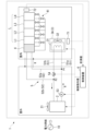
- FIG. 1 is a diagram showing an overall configuration of a cooling system according to a first embodiment.
- the cooling system 1 is a system for cooling a room of a facility (such as a server room or a data center) in which multiple load devices L (L1, L2, L3, L4, ...) are installed and the load devices L.
- the load devices L are devices having heat generating elements (such as a CPU, a GPU, etc.), such as servers and communication devices.
- the air conditioning means 3 is an air conditioner 3A that cools the air in the room.
- the air conditioner 3A is equipped with a heat exchanger 31 and an air conditioner fan 32.
- the heat exchanger 31 exchanges heat between the heat medium R cooled by the cooling device 2 and the air in the room that has been warmed by the load equipment L.
- the air conditioner fan 32 blows the air cooled by the heat exchanger 31 into the room. Note that while FIG. 1 shows an example in which only one air conditioning means 3 is provided in the room, this is not limiting. In other embodiments, multiple air conditioning means 3 may be provided in the room.
- the heat medium loop 5 consists of a first line 51 and a second line 52.
- the first line 51 is a flow path that circulates the heat medium R via the air conditioner 3A.
- the second line 52 is a flow path that branches off from the first line 51 and circulates the heat medium R via the local cooling device 4.
- a pump 53 is provided in the first line 51, which sucks in the heat medium R cooled by the cooling device 2 and sends it out to the downstream side of the first line 51 (the air conditioner 3A side).
- the first line 51 has a first low-temperature line 51a that supplies the heat medium R to the air conditioner 3A, and a first high-temperature line 51b that flows downstream the heat medium R that has completed heat exchange in the heat exchanger 31 of the air conditioner 3A.
- the second line 52 has a second low-temperature line 52a that supplies the heat medium R to the local cooling device 4, and a second high-temperature line 52b that flows downstream the heat medium R that has been warmed by the heat generating element of the load device L.
- the second line 52 in this embodiment is connected in series with the first line 51.
- the second low-temperature line 52a of the second line 52 branches off from the first high-temperature line 51b of the first line 51 at the branch point P1.
- the second line 52 has a local cooling loop 41 in which the local cooling device 4 branches into multiple flow paths.
- the local cooling loop 41 uses a pipe with a smaller diameter than the pipe of the first line 51.
- the first line 51 is designed to have a smaller pressure loss than the second line 52.
- the second line 52 is not limited to a configuration in which the local cooling loop 41 described above has a small diameter, and may have various other configurations.
- the diameter of at least one of the second low temperature line 52a and the second high temperature line 52b of the second line 52 may be made smaller than that of the first line 51.
- the length of the piping of the second line 52 may be made longer than that of the first line 51, or the piping may be bent more than that of the first line 51, so that the second line 52 generates a larger pressure loss than the first line 51.
- an adjustment valve 54 is provided in the first line 51, which has a small pressure loss, as a means for further adjusting the flow rate of the heat medium R bypassed to the second line 52.
- the adjustment valve 54 is provided between the branch point P1 and the junction point P2 of the first line 51.
- the opening of the adjustment valve 54 may be two values, maximum (for example, fully open) or minimum (for example, fully closed), or may be adjustable to any value in the range from maximum to minimum. Since the first line 51 has a smaller pressure loss than the second line 52 and the heat medium R flows more easily, the larger the opening of the adjustment valve 54, the larger the flow rate of the heat medium R flowing downstream of the first line 51 (first high temperature line 51b). The flow rate of the heat medium R bypassed from the branch point P1 of the first line 51 to the second line 52 decreases accordingly. When the opening of the adjustment valve 54 is maximum, only the heat medium R with a minimum flow rate according to the difference in pressure loss is bypassed to the second line 52.
- the smaller the opening of the adjustment valve 54 the smaller the flow rate of the heat medium R flowing downstream of the first line 51 (first high temperature line 51b).
- the flow rate of the heat medium R bypassed from the branch point P1 of the first line 51 to the second line 52 increases accordingly.
- the flow rates of the first line 51 and the second line 52 can be adjusted by opening and closing the adjustment valve 54.
- the control device 6 outputs control signals for controlling the operation of the cooling device 2, the air conditioner 3A, the pump 53, and the adjustment valve 54.
- the control device 6 may be installed in the same room as the air conditioner 3A and the local cooling device 4, or in another room within the facility.
- the control device 6 may also be built into the cooling device 2. The detailed functional configuration of the control device 6 will be described later.
- the power source 10 supplies power for operating each part of the cooling system 1.
- the power source 10 is, for example, a power system.
- the power source 10 may be a power generation device that uses natural energy (such as a solar power generation device, a wind power generation device, a hydroelectric power generation device, or a geothermal power generation device).
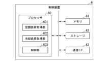
- FIG. 2 is a diagram illustrating a functional configuration of the control device according to the first embodiment.
- the control device 6 includes a processor 60 , a memory 61 , a storage 62 , and a communication interface (I/F) 63 .
- I/F communication interface
- the processor 60 operates according to a predetermined program to perform the functions of an air conditioning load acquisition unit 601, a cooling load acquisition unit 602, and a control unit 603.
- the air conditioning load acquisition unit 601 acquires the air conditioning load of the air conditioner 3A based on the temperature in the room in which the air conditioner 3A is installed (indoor temperature).
- the indoor temperature is measured by a first thermometer T1 installed near the air conditioner 3A, for example, as shown in FIG. 1.
- the cooling load acquisition unit 602 acquires the load (cooling load) of the local cooling device 4 based on the temperature of the load equipment L or the temperature of the second line 52.
- a second thermometer T2 is installed near the load equipment L indoors (such as a server rack) to measure the temperature of the load equipment L.
- the second thermometer T2 may be installed at each of the inlet (second low temperature line 52a) and outlet (second high temperature line 52b) of the local cooling device 4 to measure the temperature of the second line 52.
- the air conditioning load acquisition unit 601 acquires the air conditioning load of the air conditioner 3A (step S01).
- the air conditioning load in this embodiment is the indoor temperature measured by the first thermometer T1.
- the cooling load acquisition unit 602 acquires the cooling load of the local cooling device 4 (step S02).
- the cooling load in this embodiment is the temperature of the load device L measured by the second thermometer T2.
- the cooling load may be the rate of increase in the temperature of the load equipment L per unit time, or the difference between the temperature of the load equipment L and the room temperature. In still other embodiments, the cooling load may be the temperature difference of the heat medium R at the inlet and outlet of the local cooling device 4, or the rate of increase in the temperature difference of the heat medium R per unit time.
- control unit 603 controls the opening of the adjustment valve 54, the pump 53's pumping flow rate of the heat medium R, and the airflow rate of the air conditioner fan 32 of the air conditioner 3A based on the air conditioning load and the cooling load (step S03).
- the control unit 603 increases the opening of the adjustment valve 54. At this time, the control unit 603 reduces the pumping flow rate of the pump 53 and the airflow rate of the air conditioner fan 32. For example, the control unit 603 adjusts the opening of the adjustment valve 54 to be larger and the pumping flow rate of the pump 53 and the airflow rate of the air conditioner fan 32 to be smaller as the cooling load becomes smaller. Also, as shown in FIG. 4, the opening of the adjustment valve 54 may be maximized, the pumping flow rate of the pump 53 may be minimized, and the airflow rate of the air conditioner fan 32 may be minimized. In this way, the pressure loss of the entire cooling system 1 can be reduced, and the power consumption of the entire cooling system 1 can be reduced.
- control unit 603 adjusts the pump pressure delivery flow rate so that the pump pressure delivery flow rate becomes larger as the cooling load increases.
- the control unit 603 does not increase the airflow rate of the air conditioner fan 32.
- the airflow rate of the air conditioner fan 32 may be minimized as shown in FIG. 4. This makes it possible to increase or decrease the cooling capacity of the local cooling device 4 in accordance with the cooling load while suppressing increases in the cooling capacity and power consumption of the air conditioner 3A.
- the control unit 603 increases the opening of the adjustment valve 54.
- the control unit 603 may adjust the opening of the adjustment valve 54 so that the smaller the cooling load, the larger the opening of the adjustment valve 54, or may maximize the opening of the adjustment valve 54 as in the example of FIG. 4.
- the control unit 603 adjusts the control command values so that the pump 53's compression flow rate and the air conditioner fan 32's blowing volume are increased as the air conditioning load is increased.
- (B2) Medium room temperature and medium load
- the control unit 603 increases the flow rate of the heat medium R bypassed to the second line 52 by decreasing the opening of the adjustment valve 54.
- the opening of the adjustment valve 54 is a binary value of maximum or minimum
- the control unit 603 minimizes the opening of the adjustment valve 54.
- the control unit 603 may adjust the opening so that the opening of the adjustment valve 54 decreases as the cooling load increases.
- the control unit 603 increases the flow rate of the heat medium R bypassed to the second line 52 by decreasing the opening of the adjustment valve 54.
- the control unit 603 minimizes the opening of the adjustment valve 54.
- the control unit 603 may adjust the opening so that the opening of the adjustment valve 54 decreases as the cooling load increases.
- control unit 603 increases the pressure-feed flow rate of the pump 53 and increases the airflow rate of the air conditioner fan 32. As shown in FIG. 4, the pressure-feed flow rate of the pump 53 and the airflow rate of the air conditioner fan 32 may be maximized. This can increase the cooling capacity of the air conditioner 3A and appropriately adjust the cooling capacity of the local cooling device 4.
- the control unit 603 reduces the opening of the adjustment valve 54 to reduce the difference in pressure loss between the first line 51 and the second line 52, thereby increasing the flow rate of the heat medium R bypassed to the second line 52.
- the control unit 603 also increases the pressure-feed flow rate of the pump 53 to increase the air flow rate of the air conditioner fan 32.
- the opening of the adjustment valve 54 may be minimized, and the pressure-feed flow rate of the pump 53 and the air flow rate of the air conditioner fan 32 may be maximized. This can increase the cooling capacity of the air conditioner 3A and the local cooling device 4.
- the control device 6 executes the series of processes shown in FIG. 3 at predetermined intervals while the cooling system 1 is in operation, thereby appropriately controlling the power consumption of the entire cooling system 1 and adjusting the cooling capacity of the air conditioner 3A and the local cooling device 4.
- the cooling system 1 includes the cooling device 2 that cools the heat medium R, the air conditioning means (air conditioner 3A) that receives the heat medium R and cools the interior of a room in which load equipment L is installed, the local cooling device 4 that receives the heat medium R and cools the load equipment L, and the heat medium loop 5 that includes the first line 51 that circulates the heat medium R from the cooling device 2 via the air conditioner 3A, and the second line 52 that branches off from the first line 51 and circulates the heat medium R via the local cooling device 4.
- the first line 51 has a smaller pressure loss than the second line 52.
- the heat generating element of the load equipment L is hotter than the room temperature, so even if the heat medium R after heat exchange by the heat exchanger 31 of the air conditioner 3A is reused, the local cooling device 4 can sufficiently remove heat from the heat generating element of the load equipment L. Therefore, by further using the heat medium R used by the air conditioner 3A in the downstream local cooling device 4, it is not necessary to provide multiple cooling devices 2 for each of the air conditioner 3A and the local cooling device 4, and the heat medium R cooled by one cooling device 2 can be used to the maximum. In other words, with a simple configuration in which only one cooling device 2 is installed, both the room and the load equipment L can be cooled, and the power consumption of the entire cooling system 1 can be reduced.
- the flow rate of the heat medium R bypassed from the first line 51 to the second line 52 can be adjusted by adjusting the difference in pressure loss by making a difference in the diameter of the pipes used in the first line 51 and the second line 52 depending on the number of load equipment L and the load (heat generation amount).
- the cooling system 1 has a simple configuration with a first line 51 and a second line 52 with different pressure losses, and can adjust the flow rate and cooling capacity of the heat medium R supplied from one cooling device 2 to the air conditioner 3A and the local cooling device 4.
- the first line 51 is also provided with an adjustment valve 54 that can adjust the flow rate of the heat medium R in the first line 51 and the second line 52.
- the cooling system 1 can adjust the flow rate in the first line 51 and the second line 52 by opening and closing the adjustment valve 54, and adjust the cooling capacity of the air conditioner 3A and the local cooling device 4.
- the cooling system 1 further includes an air conditioning load acquisition unit 601 that acquires the air conditioning load of the air conditioner 3A based on the indoor temperature, a cooling load acquisition unit 602 that acquires the cooling load of the local cooling device 4 based on the temperature of the load equipment L or the temperature of the second line 52, and a control unit 603 that controls the opening degree of the adjustment valve 54 based on the air conditioning load and the cooling load.
- an air conditioning load acquisition unit 601 that acquires the air conditioning load of the air conditioner 3A based on the indoor temperature
- a cooling load acquisition unit 602 that acquires the cooling load of the local cooling device 4 based on the temperature of the load equipment L or the temperature of the second line 52
- a control unit 603 that controls the opening degree of the adjustment valve 54 based on the air conditioning load and the cooling load.
- the cooling system 1 can appropriately adjust the flow rate of the heat medium R bypassed to the second line 52 according to the air conditioning load required by the air conditioner 3A to cool the room and the cooling load required by the local cooling device 4 to cool the load equipment L.
- control unit 603 reduces the opening of the adjustment valve 54 when the air conditioning load is less than the low air conditioning load threshold (low room temperature) and the cooling load is equal to or greater than the high cooling load threshold (high load).
- the control unit 603 increases the opening of the adjustment valve 54 when the air conditioning load is equal to or greater than the high air conditioning load threshold (high room temperature) and the cooling load is less than the low cooling load threshold (low load).
- the cooling system 1 can reduce pressure loss throughout the system and increase the cooling capacity of the air conditioner 3A.
- the air conditioning means is an air conditioner 3A having an air conditioner fan 32, and the control unit 603 stops the air conditioner fan 32 when the air conditioning load is less than the low air conditioning load threshold (low room temperature) and the cooling load is equal to or greater than the high cooling load threshold (high load).
- the cooling system 1 can minimize the amount of power used by the air conditioner 3A when cooling of the room is not required.
- FIG. 5 is a diagram showing an overall configuration of a cooling system according to the second embodiment.
- the heat medium loop 5 has the first line 51 and the second line 52 that are directly connected to each other.
- the heat medium loop 5 has the first line 51 and the second line 52 that are connected in parallel to each other.
- the second low-temperature line 52a of the second line 52 branches off from the first low-temperature line 51a of the first line 51 at a branch point P1. Then, the second high-temperature line 52b of the second line 52 merges with the first high-temperature line 51b of the first line 51 at a merge point P2.
- the adjustment valve 54 is provided between the branch point P1 and the junction point P2, as in the first embodiment. When the adjustment valve 54 is fully closed, the heat medium R stops flowing through the first line 51 and flows only through the second line 52. In other words, all of the heat medium R is supplied to the local cooling device 4.
- FIG. 6 is a diagram illustrating an example of a control command value of the control device according to the second embodiment. Moreover, the control unit 603 of the control device 6 according to this embodiment determines the control command value as shown in FIG. 6 instead of FIG.
- the control unit 603 when the air conditioning load is less than the low air conditioning load threshold (low room temperature), the control unit 603 minimizes the opening of the adjustment valve 54 (fully closed). The control unit 603 also stops the air conditioner fan 32.
- the cooling system 1 can supply the heat medium R only to the local cooling device 4, without supplying it to the air conditioner 3A. This eliminates the need to flow the heat medium R to unnecessary locations (air conditioner 3A), making it possible to reduce power consumption of the pump 53, etc. Also, by stopping the air conditioner fan 32, power consumption can be further reduced. In addition, since the heat medium R cooled by the cooling device 2 is directly supplied to the local cooling device 4, the cooling capacity of the local cooling device 4 can be greatly improved compared to the first embodiment.
- FIG. 7 is a diagram showing an overall configuration of a cooling system according to the third embodiment.
- the air conditioning unit 3 according to this embodiment is a fin tube 3B.
- FIG. 7 shows an example in which the air conditioner 3A in the first embodiment is replaced with fin tubes 3B, this is not limiting. In other embodiments, the air conditioner 3A in the second embodiment (FIG. 5) may be replaced with fin tubes 3B.
- control unit 603 of the control device 6 does not perform the process of determining the control command value for the air conditioner fan 32 shown in Figures 4 and 6.
- the indoor temperature may be low throughout the year.
- equipment with high cooling capacity such as the air conditioner 3A will not be necessary.
- the air conditioner 3A by replacing the air conditioner 3A with fin tubes 3B as the air conditioning means 3, it is possible to significantly reduce the power consumption of the cooling system 1 while ensuring the cooling capacity of the room with the flow rate of the heat medium R flowing through the fin tubes 3B.
- FIG. 8 is a diagram showing the overall configuration of a cooling system according to the fourth embodiment.
- the opening degree of the adjustment valve 54 has two values, maximum (fully open) and minimum (fully closed).
- the first line 51 is provided with a first valve 55 capable of adjusting the flow rate of the heat medium R flowing through the first line 51 (supplied to the air conditioning means 3).
- the second line 52 is provided with a second valve 56 capable of adjusting the flow rate of the heat medium R flowing through the second line 52 (supplied to the local cooling device 4).
- FIG. 8 shows an example in which the first valve 55 and the second valve 56 are added to the configuration of the first embodiment, this is not limiting. In other embodiments, the first valve 55 and the second valve 56 may be added to the configuration of the second embodiment (FIG. 5) or the third embodiment (FIG. 7).
- control unit 603 of the control device 6 adjusts the opening of the first valve 55 and the second valve 56 in accordance with the air conditioning load and the cooling load while minimizing the opening of the adjustment valve 54.
- the cooling system 1 can precisely adjust the flow rate of the heat medium R in the first line 51 and the second line 52 while keeping the adjustment valve 54 simple in configuration.
- FIG. 9 is a diagram showing the configuration of a second line and a local cooling device according to the fifth embodiment. As shown in Fig. 9, one local cooling device 4 may be provided for each load device L. Fig. 9 shows an example in which one local cooling device 4A to 4D is provided for each of four load devices L1 to L4.
- the second low-temperature line 52a of the second line 52 branches off and is connected to each local cooling device 4 (4A to 4D).
- a local cooling valve 42 (42A to 42D) is provided on each branch of the second low-temperature line 52a to each local cooling device 4.
- the local cooling valve 42 adjusts the flow rate of the heat medium R supplied from the second line 52 (second low-temperature line 52a) to each local cooling device 4.
- the heat medium R discharged from each of the local cooling devices 4A to 4D joins the second high-temperature line 52b of the second line 52.
- the cooling system 1 can appropriately and efficiently cool each load device L using multiple local cooling devices 4. In this way, when the amount of heat generated by each load device L differs, it is possible to prevent some load devices L from becoming overcooled or some load devices L from becoming insufficiently cooled.
- the cooling system 1 includes a cooling device 2 that cools a heat medium R, an air conditioning means 3 that receives the heat medium R and cools a room in which a load device L is installed, a local cooling device 4 that receives the heat medium R and cools the load device L, and a heat medium loop 5 that includes a first line 51 that circulates the heat medium R from the cooling device 2 via the air conditioning means 3, and a second line 52 that branches off from the first line 51 and circulates the heat medium R via the local cooling device 4.
- the first line 51 has a smaller pressure loss than the second line 52.
- the heat generating element of the load equipment L is usually at a higher temperature than the room temperature, so even if the heat medium R after heat exchange by the heat exchanger 31 of the air conditioner 3A is reused, the local cooling device 4 can sufficiently remove heat from the heat generating element of the load equipment L. Therefore, by further using the heat medium R used by the air conditioner 3A in the downstream local cooling device 4, it is not necessary to provide multiple cooling devices 2 for each of the air conditioner 3A and the local cooling device 4, and the heat medium R cooled by one cooling device 2 can be used to the maximum. In other words, with a simple configuration in which only one cooling device 2 is installed, both the room and the load equipment L can be cooled, and the power consumption of the entire cooling system 1 can be reduced.
- the flow rate of the heat medium R bypassed from the first line 51 to the second line 52 can be adjusted by adjusting the difference in pressure loss by making a difference in the diameter of the pipes used in the first line 51 and the second line 52 depending on the number of load equipment L and the load (heat generation amount).
- the cooling system 1 has a simple configuration with a first line 51 and a second line 52 with different pressure losses, and can adjust the flow rate and cooling capacity of the heat medium R supplied from one cooling device 2 to the air conditioner 3A and the local cooling device 4.
- the first line 51 is provided with an adjustment valve 54 that, when the opening degree is decreased, increases the ratio of the flow rate of the heat medium R that branches into the second line 52 to the flow rate of the heat medium R that flows without branching into the second line 52.
- the cooling system 1 can adjust the proportion of the heat medium R that flows into the second line 52 out of the total amount of heat medium R by increasing or decreasing the opening of the adjustment valve 54, thereby adjusting the cooling capacity of the air conditioning means 3 and the local cooling device 4.
- the cooling system 1 further includes an air conditioning load acquisition unit 601 that acquires the air conditioning load of the air conditioning means 3 based on the room temperature, a cooling load acquisition unit 602 that acquires the cooling load of the local cooling device 4 based on the temperature of the load equipment L or the temperature of the second line 52, and a control unit 603 that controls the opening degree of the adjustment valve 54 based on the air conditioning load and the cooling load.
- an air conditioning load acquisition unit 601 that acquires the air conditioning load of the air conditioning means 3 based on the room temperature
- a cooling load acquisition unit 602 that acquires the cooling load of the local cooling device 4 based on the temperature of the load equipment L or the temperature of the second line 52
- a control unit 603 that controls the opening degree of the adjustment valve 54 based on the air conditioning load and the cooling load.
- the cooling system 1 can appropriately adjust the flow rate of the heat medium R bypassed to the second line 52 according to the air conditioning load required by the air conditioner 3A to cool the room and the cooling load required by the local cooling device 4 to cool the load equipment L.
- control unit 603 reduces the opening degree of the adjustment valve 54 when the air conditioning load is less than the low air conditioning load threshold and the cooling load is equal to or greater than the high cooling load threshold.
- the cooling system 1 can increase the flow rate of the heat medium R bypassed to the second line 52, thereby increasing the cooling capacity of the local cooling device 4.
- control unit 603 increases the opening degree of the adjustment valve 54 when the air conditioning load is equal to or greater than the high air conditioning load threshold and the cooling load is less than the low cooling load threshold.
- the cooling system 1 can reduce pressure loss throughout the system and increase the cooling capacity of the air conditioner 3A.
- the first line 51 and the second line 52 are connected in parallel, and the control unit 603 closes the adjustment valve 54 to stop the supply of the heat medium R to the air conditioning means 3.
- the cooling system 1 can supply the heat medium R only to the local cooling device 4, without supplying it to the air conditioning means 3. This eliminates the need to flow the heat medium R to unnecessary locations (air conditioning means 3), making it possible to reduce power consumption of the pump 53, etc. Also, by stopping the air conditioner fan 32, power consumption can be further reduced. In addition, since the heat medium R cooled by the cooling device 2 is directly supplied to the local cooling device 4, the cooling capacity of the local cooling device 4 can be greatly improved.
- the air conditioning means 3 is an air conditioner 3A having an air conditioner fan 32, and the control unit 603 stops the air conditioner fan 32 when the air conditioning load is less than the low air conditioning load threshold and the cooling load is equal to or greater than the high cooling load threshold.
- the cooling system 1 can minimize the amount of power used by the air conditioner 3A when cooling of the room is not required.
- the air conditioning means 3 is a fin tube 3B.
- the indoor temperature may be low throughout the year.
- equipment with high cooling capacity such as the air conditioner 3A will not be necessary.
- the air conditioner 3A by replacing the air conditioner 3A with fin tubes 3B as the air conditioning means 3, it is possible to significantly reduce the power consumption of the cooling system 1 while ensuring the cooling capacity of the room with the flow rate of the heat medium R flowing through the fin tubes 3B.
- a plurality of local cooling devices 4 are provided corresponding to a plurality of load devices L.
Landscapes
- Engineering & Computer Science (AREA)
- General Engineering & Computer Science (AREA)
- Theoretical Computer Science (AREA)
- Mechanical Engineering (AREA)
- Physics & Mathematics (AREA)
- Combustion & Propulsion (AREA)
- Chemical & Material Sciences (AREA)
- Thermal Sciences (AREA)
- General Physics & Mathematics (AREA)
- Human Computer Interaction (AREA)
- Microelectronics & Electronic Packaging (AREA)
- Computer Hardware Design (AREA)
- Life Sciences & Earth Sciences (AREA)
- Sustainable Development (AREA)
- Air Conditioning Control Device (AREA)
- Other Air-Conditioning Systems (AREA)
Abstract
冷却システムは、熱媒体を冷却する冷却装置と、前記熱媒体が供給されて負荷機器が設置された室内を冷却する空調手段と、前記熱媒体が供給されて前記負荷機器を冷却する局所冷却装置と、前記冷却装置から前記空調手段を経由して前記熱媒体を流通させる第1ラインと、前記第1ラインから分岐し、前記局所冷却装置を経由して前記熱媒体を流通させる第2ラインとからなる熱媒体ループと、を備え、前記第1ラインは、前記第2ラインよりも圧力損失が小さい。
Description
本開示は、冷却システムに関する。本願は、2023年6月30日に日本に出願された特願2023-108617号について優先権を主張し、その内容をここに援用する。
たとえばIT機器(サーバなど)といった熱を発生する負荷機器を多数設置したデータセンターなどの室内熱媒体を冷却する熱源装置(チラー)と、熱源装置から供給された熱媒体で室内を冷却する空調機とを備える冷却システムが設けられている(特許文献1~3を参照)。
近年では、冷却システムは、室内を冷却する空調機に加えて、負荷機器のCPUやGPUなどの高発熱体を冷却する局所冷却装置(チップ冷却など)をさらに備える場合がある。従来の技術では、空調機用の熱源装置と、局所冷却装置用の熱源装置との両方を設け、空調機と局所冷却装置とを個別に制御する必要があった。そうすると、待機状態(アイドリング状態)においても各機器で動力が消費されることから、冷却システム全体の電力消費量が増大してしまう。
本開示の目的は、簡易な構成で室内および負荷機器の両方を冷却できるとともに、電力消費量を低減することができる冷却システムを提供することにある。
本開示の一態様によれば、冷却システムは、熱媒体を冷却する冷却装置と、前記熱媒体が供給されて負荷機器が設置された室内を冷却する空調手段と、前記熱媒体が供給されて前記負荷機器を冷却する局所冷却装置と、前記冷却装置から前記空調手段を経由して前記熱媒体を流通させる第1ラインと、前記第1ラインから分岐し、前記局所冷却装置を経由して前記熱媒体を流通させる第2ラインとからなる熱媒体ループと、を備え、前記第1ラインは、前記第2ラインよりも圧力損失が小さい。
上記態様によれば、簡易な構成で室内および負荷機器の両方を冷却できるとともに、電力消費量を低減することができる。
<第1の実施形態>
以下、図1~図4を参照しながら第1の実施形態について詳しく説明する。
以下、図1~図4を参照しながら第1の実施形態について詳しく説明する。
(冷却システムの全体構成)
図1は、第1の実施形態に係る冷却システムの全体構成を示す図である。
図1に示すように、冷却システム1は、複数の負荷機器L(L1,L2,L3,L4,…)が設置された施設(サーバ室、データセンターなど)の室内および負荷機器Lを冷却するためのシステムである。負荷機器Lは、たとえばサーバや通信機器などの発熱体(CPU、GPUなど)を有する機器である。
図1は、第1の実施形態に係る冷却システムの全体構成を示す図である。
図1に示すように、冷却システム1は、複数の負荷機器L(L1,L2,L3,L4,…)が設置された施設(サーバ室、データセンターなど)の室内および負荷機器Lを冷却するためのシステムである。負荷機器Lは、たとえばサーバや通信機器などの発熱体(CPU、GPUなど)を有する機器である。
冷却システム1は、冷却装置2と、空調手段3と、局所冷却装置4と、熱媒体ループ5と、制御装置6と、電源10とを備えている。
冷却装置2は、たとえば空冷式のチラーや、フリークーリング方式の冷却塔などであり、室外に設置される。冷却装置2は、ファン21を備えている。冷却装置2は、ファン21で低温の外気を取り込んで、空調手段3および局所冷却装置4に供給する熱媒体Rを冷却する。熱媒体Rは、たとえばブラインなど、どのような態様であってもよい。
空調手段3は、室内の空気を冷却する空調機3Aである。空調機3Aは、熱交換器31と、空調機ファン32とを備えている。熱交換器31は、冷却装置2により冷却された熱媒体Rと、負荷機器Lにより暖められた室内の空気との間で熱交換を行う。空調機ファン32は、熱交換器31により冷却された空気を室内に吹き出す。なお、図1には室内に空調手段3が1つのみ設けられている例が示されているが、これに限られることはない。他の実施形態では、室内に空調手段3が複数設けられていてもよい。
局所冷却装置4は、複数の負荷機器Lそれぞれを冷却するチップ冷却装置である。局所冷却装置4は、局所冷却用ループ41を備えている。局所冷却用ループ41は、熱媒体ループ5から冷却装置2により冷却された熱媒体Rを取り込んで各負荷機器Lに分配するとともに、各負荷機器Lから排出された熱媒体Rを熱媒体ループ5に戻す。各負荷機器Lに分配して供給された熱媒体Rは、負荷機器Lの発熱体から熱を奪うことにより、負荷機器Lを冷却する。
熱媒体ループ5は、第1ライン51と、第2ライン52とからなる。第1ライン51は、空調機3Aを経由して熱媒体Rを流通させる流路である。第2ライン52は、第1ライン51から分岐し、局所冷却装置4を経由して熱媒体Rを流通させる流路である。また、第1ライン51には、ポンプ53が設けられており、冷却装置2により冷却された熱媒体Rを吸い込んで第1ライン51の下流側(空調機3A側)へ送出する。
第1ライン51は、熱媒体Rを空調機3Aに供給する第1低温ライン51aと、空調機3Aの熱交換器31で熱交換を終えた熱媒体Rを下流に流す第1高温ライン51bとを有している。第2ライン52は、熱媒体Rを局所冷却装置4に供給する第2低温ライン52aと、負荷機器Lの発熱体に温められた熱媒体Rを下流側に流す第2高温ライン52bとを有している。本実施形態に係る第2ライン52は、第1ライン51と直列に接続される。第2ライン52の第2低温ライン52aは、第1ライン51の第1高温ライン51bから分岐点P1において分岐する。その後、第2ライン52の第2高温ライン52bは、第1ライン51の第1高温ライン51bに、分岐点P1よりも下流側の合流点P2において合流する。通常、負荷機器Lの発熱体は室内温度よりも高温になるので、空調機3Aの熱交換器31により熱交換された後の熱媒体Rを再利用したとしても、局所冷却装置4は十分に負荷機器Lの発熱体から熱を奪うことができる。このため、空調機3Aで利用された熱媒体Rを下流側の局所冷却装置4でさらに利用することにより、空調機3Aと局所冷却装置4とのそれぞれに対して複数の冷却装置2を設ける必要がなく、1台の冷却装置2が冷却した熱媒体Rを最大限に利用することができる。
なお、上記したように、本実施形態に係る第2ライン52は、局所冷却装置4が複数の流路に分岐した局所冷却用ループ41を有している。また、局所冷却用ループ41は、第1ライン51の配管と比較して径の小さい配管を使用する。このように配管の径を異ならせることで、第1ライン51と第2ライン52とでは、圧力損失が不均衡となる。つまり、第1ライン51は、第2ライン52よりも圧力損失が小さくなるように設計される。配管の径に差を付けるなどして第1ライン51および第2ライン52の圧力損失の差を調節することにより、第1ライン51から第2ライン52にバイパスする熱媒体Rの流量を調節することができる。なお、第1ライン51と第2ライン52の圧力損失を不均衡とすることが可能であれば、第2ライン52は、上記した局所冷却用ループ41を小径とする構成に限られることなく、他のさまざまな構成を有していてよい。たとえば、他の実施形態では、局所冷却用ループ41に代えて、または、局所冷却用ループ41に加えて、第2ライン52の第2低温ライン52aおよび第2高温ライン52bの少なくとも一方の配管の径を第1ライン51の配管より小さくしてもよい。さらに他の実施形態では、第2ライン52(局所冷却用ループ41、第2低温ライン52a、および第2高温ライン52b)の配管の長さを第1ライン51よりも長くする、あるいは、配管の屈曲を第1ライン51よりも多くするなどして、第2ライン52に第1ライン51よりも大きい圧力損失が生じるようにしてもよい。
また、第2ライン52へバイパスする熱媒体Rの流量をさらに調節する手段として、本実施形態では、圧力損失が小さい第1ライン51に調節バルブ54が設けられる。本実施形態では、第1ライン51の分岐点P1と合流点P2との間に調節バルブ54が設けられる。
調節バルブ54の開度は、最大(たとえば全開)または最小(たとえば全閉)の2値であってもよいし、最大から最小の範囲で任意の値に調節可能であってもよい。第2ライン52よりも第1ライン51の圧力損失が小さく熱媒体Rが流れやすいことから、調節バルブ54の開度を大きくするほど、第1ライン51(第1高温ライン51b)の下流側へ流れる熱媒体Rの流量が多くなる。その分、第1ライン51の分岐点P1から第2ライン52へバイパスする熱媒体Rの流量が減少する。調節バルブ54の開度が最大の場合には、圧力損失の差に応じた最小流量の熱媒体Rのみが第2ライン52にバイパスする。一方、調節バルブ54の開度を小さくするほど、第1ライン51(第1高温ライン51b)の下流側へ流れる熱媒体Rの流量が少なくなる。その分、第1ライン51の分岐点P1から第2ライン52へバイパスする熱媒体Rの流量が増加する。つまり、調節バルブ54の開閉により第1ライン51および第2ライン52の流量を調節することができる。
制御装置6は、冷却装置2、空調機3A、ポンプ53、および調節バルブ54の動作を制御するための制御信号を出力する。制御装置6は、空調機3Aや局所冷却装置4と同じ室内に設置されてもよいし、施設内の他の部屋などに設置されてもよい。また、制御装置6は、冷却装置2に内蔵されたものであってもよい。制御装置6の詳細な機能構成については後述する。
電源10は、冷却システム1の各部が動作するための電力を供給する。電源10は、たとえば電力系統である。なお、他の実施形態では、電源10は自然エネルギーを利用した発電装置(太陽光発電装置、風力発電装置、水力発電装置、地熱発電装置など)であってもよい。
(制御装置の機能構成)
図2は、第1の実施形態に係る制御装置の機能構成を示す図である。
図2に示すように、制御装置6は、プロセッサ60と、メモリ61と、ストレージ62と、通信インタフェース(I/F)63とを備えている。
図2は、第1の実施形態に係る制御装置の機能構成を示す図である。
図2に示すように、制御装置6は、プロセッサ60と、メモリ61と、ストレージ62と、通信インタフェース(I/F)63とを備えている。
プロセッサ60は、所定のプログラムに従って動作することにより、空調負荷取得部601、冷却負荷取得部602、制御部603としての機能を発揮する。
空調負荷取得部601は、空調機3Aが設置された室内の温度(室内温度)に基づいて、空調機3Aの空調負荷を取得する。室内温度は、たとえば図1に示すように、空調機3Aの近傍に設置された第1温度計T1により計測される。
冷却負荷取得部602は、負荷機器Lの温度または第2ライン52の温度に基づいて、局所冷却装置4の負荷(冷却負荷)を取得する。たとえば、図1に示すように、室内の負荷機器Lの近傍(サーバラックなど)に第2温度計T2が設置され、負荷機器Lの温度が計測される。また、他の実施形態では、第2温度計T2は、局所冷却装置4の入口(第2低温ライン52a)および出口(第2高温ライン52b)のそれぞれに設けられ、第2ライン52の温度が計測されてもよい。
制御部603は、空調負荷および冷却負荷に基づいて、調節バルブ54の開度を制御する。また、制御部603は、空調負荷および冷却負荷に基づいて、ポンプ53や空調機3Aの空調機ファン32の制御を行ってもよい。
なお、プロセッサ60が実行する所定のプログラムは、コンピュータ読み取り可能な記録媒体に記憶される。また、コンピュータ読み取り可能な記録媒体とは、磁気ディスク、光磁気ディスク、CD-ROM、DVD-ROM、半導体メモリ等をいう。また、このコンピュータプログラムを通信回線によってコンピュータに配信し、この配信を受けたコンピュータが当該プログラムを実行するようにしてもよい。さらに、このプログラムは、上述した機能の一部を実現するためのものであってもよい。さらに、上述した機能をコンピュータシステムにすでに記録されているプログラムとの組み合わせで実現できるもの、いわゆる差分ファイル(差分プログラム)であってもよい。
メモリ61は、プロセッサ60の動作に必要なメモリ領域を有する。
ストレージ62は、いわゆる補助記憶装置であって、例えば、HDD(Hard Disk Drive)、SSD(Solid State Drive)等である。ストレージ62には、プロセッサ60の各部が処理中に取得、生成、参照するデータが格納される。
通信I/F63は、各機器との間で信号(制御指令値、計測値など)の送受信を行う。
(制御装置の処理フロー)
図3は、第1の実施形態に係る制御装置の処理の一例を示すフローチャートである。
図4は、第1の実施形態に係る制御装置の制御指令値の一例を示す図である。
以下、図3~図4を参照しながら、制御装置6の処理の流れについて説明する。
図3は、第1の実施形態に係る制御装置の処理の一例を示すフローチャートである。
図4は、第1の実施形態に係る制御装置の制御指令値の一例を示す図である。
以下、図3~図4を参照しながら、制御装置6の処理の流れについて説明する。
まず、空調負荷取得部601は、空調機3Aの空調負荷を取得する(ステップS01)。たとえば、本実施形態に係る空調負荷は、第1温度計T1が計測した室内温度である。
次に、冷却負荷取得部602は、局所冷却装置4の冷却負荷を取得する(ステップS02)。たとえば、本実施形態に係る冷却負荷は、第2温度計T2が計測した負荷機器Lの温度である。
なお、他の実施形態では、冷却負荷は、単位時間あたりの負荷機器Lの温度の上昇率や、負荷機器Lの温度と室内温度との差などであってもよい。また、さらに他の実施形態では、冷却負荷は、局所冷却装置4の出入口における熱媒体Rの温度差、単位時間あたりの熱媒体Rの温度差の上昇率などであってもよい。
次に、制御部603は、空調負荷および冷却負荷に基づいて、調節バルブ54の開度、ポンプ53の熱媒体Rの圧送流量、空調機3Aの空調機ファン32の送風量を制御する(ステップS03)。
具体的には、制御部603は、図4に示すように、空調負荷および冷却負荷の組み合わせ(負荷状態)により、各部の制御指令値を決定する。
(A1)低室温かつ低負荷
空調負荷が空調低負荷側閾値未満(低室温)であり、かつ、冷却負荷が冷却低負荷側閾値未満(低負荷)である場合、制御部603は、調節バルブ54の開度を増加させる。また、このとき、制御部603は、ポンプ53の圧送流量を減少させ、空調機ファン32の送風量を減少させる。たとえば、制御部603は、冷却負荷が小さくなるほど、調節バルブ54の開度が大きくなるように、かつ、ポンプ53の圧送流量および空調機ファン32の送風量が少なくように調節する。また、図4に示すように、調節バルブ54の開度を最大、ポンプ53の圧送流量を最小、空調機ファン32の送風量を最小としてもよい。このようにすることで、冷却システム1全体の圧力損失を小さくするとともに、冷却システム1全体の電力使用量を低減することができる。
空調負荷が空調低負荷側閾値未満(低室温)であり、かつ、冷却負荷が冷却低負荷側閾値未満(低負荷)である場合、制御部603は、調節バルブ54の開度を増加させる。また、このとき、制御部603は、ポンプ53の圧送流量を減少させ、空調機ファン32の送風量を減少させる。たとえば、制御部603は、冷却負荷が小さくなるほど、調節バルブ54の開度が大きくなるように、かつ、ポンプ53の圧送流量および空調機ファン32の送風量が少なくように調節する。また、図4に示すように、調節バルブ54の開度を最大、ポンプ53の圧送流量を最小、空調機ファン32の送風量を最小としてもよい。このようにすることで、冷却システム1全体の圧力損失を小さくするとともに、冷却システム1全体の電力使用量を低減することができる。
(A2)低室温かつ中負荷
空調負荷が空調低負荷側閾値未満(低室温)であり、かつ、冷却負荷が冷却低負荷側閾値以上、冷却高負荷側閾値未満(中負荷)である場合、制御部603は、調節バルブ54の開度を減少させることにより、第2ライン52へバイパスする熱媒体Rの流量を増加させる。たとえば調節バルブ54の開度が最大または最小の2値である場合、制御部603は、調節バルブ54の開度を最小とする。調節バルブ54の開度を任意の値に調節可能な場合、制御部603は、冷却負荷が大きくなるほど調節バルブ54の開度が小さくなるように開度を調節してもよい。また、制御部603は、冷却負荷が大きくなるほどポンプ圧送流量が大きくなるように調節する。一方で、制御部603は、空調機ファン32の送風量は増加させない。また、図4に示すように空調機ファン32の送風量を最小としてもよい。これにより、空調機3Aの冷却能力および電力使用量の増加を抑制しつつ、冷却負荷に応じて局所冷却装置4による冷却能力を増減させることができる。
空調負荷が空調低負荷側閾値未満(低室温)であり、かつ、冷却負荷が冷却低負荷側閾値以上、冷却高負荷側閾値未満(中負荷)である場合、制御部603は、調節バルブ54の開度を減少させることにより、第2ライン52へバイパスする熱媒体Rの流量を増加させる。たとえば調節バルブ54の開度が最大または最小の2値である場合、制御部603は、調節バルブ54の開度を最小とする。調節バルブ54の開度を任意の値に調節可能な場合、制御部603は、冷却負荷が大きくなるほど調節バルブ54の開度が小さくなるように開度を調節してもよい。また、制御部603は、冷却負荷が大きくなるほどポンプ圧送流量が大きくなるように調節する。一方で、制御部603は、空調機ファン32の送風量は増加させない。また、図4に示すように空調機ファン32の送風量を最小としてもよい。これにより、空調機3Aの冷却能力および電力使用量の増加を抑制しつつ、冷却負荷に応じて局所冷却装置4による冷却能力を増減させることができる。
(A3)低室温かつ高負荷
空調負荷が空調低負荷側閾値未満(低室温)であり、かつ、冷却負荷が冷却高負荷側閾値以上(高負荷)である場合、制御部603は、冷却負荷が大きくなるほど調節バルブ54の開度を小さくする。このようにして、制御部603は、第1ライン51と第2ライン52との圧力損失の差を小さくして、第2ライン52にバイパスする熱媒体Rの流量を増やす。また、制御部603は、ポンプ圧送流量を増加させ、空調機ファン32の送風量を減少させる。また、図4に示すように調節バルブ54の開度を最小とし、ポンプ53の圧送流量を最大、空調機ファン32を停止としてもよい。これにより、空調機3Aにおける電力の使用量を低減させることができる。また、空調機3Aで利用される熱媒体Rの流量を減らした分、局所冷却装置4による冷却能力を増大させることができる。
空調負荷が空調低負荷側閾値未満(低室温)であり、かつ、冷却負荷が冷却高負荷側閾値以上(高負荷)である場合、制御部603は、冷却負荷が大きくなるほど調節バルブ54の開度を小さくする。このようにして、制御部603は、第1ライン51と第2ライン52との圧力損失の差を小さくして、第2ライン52にバイパスする熱媒体Rの流量を増やす。また、制御部603は、ポンプ圧送流量を増加させ、空調機ファン32の送風量を減少させる。また、図4に示すように調節バルブ54の開度を最小とし、ポンプ53の圧送流量を最大、空調機ファン32を停止としてもよい。これにより、空調機3Aにおける電力の使用量を低減させることができる。また、空調機3Aで利用される熱媒体Rの流量を減らした分、局所冷却装置4による冷却能力を増大させることができる。
(B1)中室温かつ低負荷
空調負荷が空調低負荷側閾値以上、空調高負荷側閾値未満(中室温)であり、かつ、冷却負荷が冷却低負荷側閾値未満(低負荷)である場合、制御部603は、調節バルブ54の開度を増加させる。たとえば、制御部603は、冷却負荷が小さくなるほど、調節バルブ54の開度が大きくなるように調節してもよいし、図4の例のように調節バルブ54の開度を最大としてもよい。また、このとき、制御部603は、空調負荷が大きいほど、ポンプ53の圧送流量および空調機ファン32の送風量が大きくなるように、これらの制御指令値を調節する。これにより、冷却システム1全体の圧力損失を小さくし、局所冷却装置4への熱媒体Rの流量を小さくした分、ポンプ53の負荷を低減することができる。また、室内温度に応じて空調機3Aの冷却能力および電力使用量を適切に調節することができる。
空調負荷が空調低負荷側閾値以上、空調高負荷側閾値未満(中室温)であり、かつ、冷却負荷が冷却低負荷側閾値未満(低負荷)である場合、制御部603は、調節バルブ54の開度を増加させる。たとえば、制御部603は、冷却負荷が小さくなるほど、調節バルブ54の開度が大きくなるように調節してもよいし、図4の例のように調節バルブ54の開度を最大としてもよい。また、このとき、制御部603は、空調負荷が大きいほど、ポンプ53の圧送流量および空調機ファン32の送風量が大きくなるように、これらの制御指令値を調節する。これにより、冷却システム1全体の圧力損失を小さくし、局所冷却装置4への熱媒体Rの流量を小さくした分、ポンプ53の負荷を低減することができる。また、室内温度に応じて空調機3Aの冷却能力および電力使用量を適切に調節することができる。
(B2)中室温かつ中負荷
空調負荷が空調低負荷側閾値以上、空調高負荷側閾値未満(中室温)であり、かつ、冷却負荷が冷却低負荷側閾値以上、冷却高負荷側閾値未満(中負荷)である場合、制御部603は、調節バルブ54の開度を減少させることにより、第2ライン52へバイパスする熱媒体Rの流量を増加させる。たとえば調節バルブ54の開度が最大または最小の2値である場合、制御部603は、調節バルブ54の開度を最小とする。調節バルブ54の開度を任意の値に調節可能な場合、制御部603は、冷却負荷が大きくなるほど調節バルブ54の開度が小さくなるように開度を調節してもよい。また、制御部603は、空調負荷または冷却負荷が大きくなるほどポンプ圧送流量が大きくなるように調節するとともに、空調負荷が大きくなるほど空調機ファン32の送風量が大きくなるように調節する。これにより、冷却システム1全体で使用する電力を低減しつつ、空調機3Aおよび局所冷却装置4の冷却能力を適切に調節することができる。
空調負荷が空調低負荷側閾値以上、空調高負荷側閾値未満(中室温)であり、かつ、冷却負荷が冷却低負荷側閾値以上、冷却高負荷側閾値未満(中負荷)である場合、制御部603は、調節バルブ54の開度を減少させることにより、第2ライン52へバイパスする熱媒体Rの流量を増加させる。たとえば調節バルブ54の開度が最大または最小の2値である場合、制御部603は、調節バルブ54の開度を最小とする。調節バルブ54の開度を任意の値に調節可能な場合、制御部603は、冷却負荷が大きくなるほど調節バルブ54の開度が小さくなるように開度を調節してもよい。また、制御部603は、空調負荷または冷却負荷が大きくなるほどポンプ圧送流量が大きくなるように調節するとともに、空調負荷が大きくなるほど空調機ファン32の送風量が大きくなるように調節する。これにより、冷却システム1全体で使用する電力を低減しつつ、空調機3Aおよび局所冷却装置4の冷却能力を適切に調節することができる。
(B3)中室温かつ高負荷
空調負荷が空調低負荷側閾値以上、空調高負荷側閾値未満(中室温)であり、かつ、冷却負荷が冷却高負荷側閾値以上(高負荷)である場合、制御部603は、調節バルブ54の開度を減少させることにより、第1ライン51と第2ライン52との圧力損失の差を小さくして、第2ライン52にバイパスする熱媒体Rの流量を増加させる。また、制御部603は、空調負荷が大きくなるほど、ポンプ53の圧送流量および空調機ファン32の送風量が大きくなるように調節する。また、図4に示すように、調節バルブ54の開度を最小とし、ポンプ53の圧送流量を最大としてもよい。これにより、局所冷却装置4による冷却能力を増大させることができるとともに、空調機3Aおよび局所冷却装置4の冷却能力を適切に調節することができる。
空調負荷が空調低負荷側閾値以上、空調高負荷側閾値未満(中室温)であり、かつ、冷却負荷が冷却高負荷側閾値以上(高負荷)である場合、制御部603は、調節バルブ54の開度を減少させることにより、第1ライン51と第2ライン52との圧力損失の差を小さくして、第2ライン52にバイパスする熱媒体Rの流量を増加させる。また、制御部603は、空調負荷が大きくなるほど、ポンプ53の圧送流量および空調機ファン32の送風量が大きくなるように調節する。また、図4に示すように、調節バルブ54の開度を最小とし、ポンプ53の圧送流量を最大としてもよい。これにより、局所冷却装置4による冷却能力を増大させることができるとともに、空調機3Aおよび局所冷却装置4の冷却能力を適切に調節することができる。
(C1)高室温かつ低負荷
空調負荷が空調高負荷側閾値以上(高室温)であり、かつ、冷却負荷が冷却低負荷側閾値未満(低負荷)である場合、制御部603は、調節バルブ54の開度を増加させる。たとえば、制御部603は、冷却負荷が小さくなるほど、調節バルブ54の開度が大きくなるように調節する。また、制御部603は、ポンプ53の圧送流量を増加させ、空調機ファン32の送風量を増加させる。また、図4に示すように、調節バルブ54の開度を最大としてもよい。これにより、冷却システム1全体の圧力損失を小さくし、局所冷却装置4への熱媒体Rの流量を減少させた分、ポンプ53の負荷を低減することができる。また、空調機3Aの冷却能力を増大させることができる。
空調負荷が空調高負荷側閾値以上(高室温)であり、かつ、冷却負荷が冷却低負荷側閾値未満(低負荷)である場合、制御部603は、調節バルブ54の開度を増加させる。たとえば、制御部603は、冷却負荷が小さくなるほど、調節バルブ54の開度が大きくなるように調節する。また、制御部603は、ポンプ53の圧送流量を増加させ、空調機ファン32の送風量を増加させる。また、図4に示すように、調節バルブ54の開度を最大としてもよい。これにより、冷却システム1全体の圧力損失を小さくし、局所冷却装置4への熱媒体Rの流量を減少させた分、ポンプ53の負荷を低減することができる。また、空調機3Aの冷却能力を増大させることができる。
(C2)高室温かつ中負荷
空調負荷が空調高負荷側閾値以上(高室温)であり、かつ、冷却負荷が冷却低負荷側閾値以上、冷却高負荷側閾値未満(中負荷)である場合、制御部603は、調節バルブ54の開度を減少させることにより、第2ライン52へバイパスする熱媒体Rの流量を増加させる。たとえば調節バルブ54の開度が最大または最小の2値である場合、制御部603は、調節バルブ54の開度を最小とする。調節バルブ54の開度を任意の値に調節可能な場合、制御部603は、冷却負荷が大きくなるほど調節バルブ54の開度が小さくなるように開度を調節してもよい。また、制御部603は、ポンプ53の圧送流量を増加させ、空調機ファン32の送風量を増加させる。図4に示すように、ポンプ53の圧送流量および空調機ファン32の送風量を最大としてもよい。これにより、空調機3Aの冷却能力を増大させることができるとともに、局所冷却装置4の冷却能力を適切に調節することができる。
空調負荷が空調高負荷側閾値以上(高室温)であり、かつ、冷却負荷が冷却低負荷側閾値以上、冷却高負荷側閾値未満(中負荷)である場合、制御部603は、調節バルブ54の開度を減少させることにより、第2ライン52へバイパスする熱媒体Rの流量を増加させる。たとえば調節バルブ54の開度が最大または最小の2値である場合、制御部603は、調節バルブ54の開度を最小とする。調節バルブ54の開度を任意の値に調節可能な場合、制御部603は、冷却負荷が大きくなるほど調節バルブ54の開度が小さくなるように開度を調節してもよい。また、制御部603は、ポンプ53の圧送流量を増加させ、空調機ファン32の送風量を増加させる。図4に示すように、ポンプ53の圧送流量および空調機ファン32の送風量を最大としてもよい。これにより、空調機3Aの冷却能力を増大させることができるとともに、局所冷却装置4の冷却能力を適切に調節することができる。
(C3)高室温かつ高負荷
空調負荷が空調高負荷側閾値以上(高室温)であり、かつ、冷却負荷が冷却高負荷側閾値以上(高負荷)である場合、制御部603は、調節バルブ54の開度を減少させることにより、第1ライン51と第2ライン52との圧力損失の差を小さくして、第2ライン52にバイパスする熱媒体Rの流量を増加させる。また、制御部603は、ポンプ53の圧送流量を増加させ、空調機ファン32の送風量を増加させる。また、図4に示すように、調節バルブ54の開度を最小とし、ポンプ53の圧送流量および空調機ファン32の送風量を最大としてもよい。これにより、空調機3Aおよび局所冷却装置4の冷却能力を増大させることができる。
空調負荷が空調高負荷側閾値以上(高室温)であり、かつ、冷却負荷が冷却高負荷側閾値以上(高負荷)である場合、制御部603は、調節バルブ54の開度を減少させることにより、第1ライン51と第2ライン52との圧力損失の差を小さくして、第2ライン52にバイパスする熱媒体Rの流量を増加させる。また、制御部603は、ポンプ53の圧送流量を増加させ、空調機ファン32の送風量を増加させる。また、図4に示すように、調節バルブ54の開度を最小とし、ポンプ53の圧送流量および空調機ファン32の送風量を最大としてもよい。これにより、空調機3Aおよび局所冷却装置4の冷却能力を増大させることができる。
制御装置6は、冷却システム1の稼働中、所定周期毎に図3の一連の処理を実行することにより、冷却システム1全体の電力使用量や、空調機3Aおよび局所冷却装置4の冷却能力の調節を適切に制御することができる。
(作用、効果)
以上のように、本実施形態に係る冷却システム1は、熱媒体Rを冷却する冷却装置2と、熱媒体Rが供給されて負荷機器Lが設置された室内を冷却する空調手段(空調機3A)と、熱媒体Rが供給されて負荷機器Lを冷却する局所冷却装置4と、冷却装置2から空調機3Aを経由して熱媒体Rを流通させる第1ライン51と、第1ライン51から分岐し、局所冷却装置4を経由して熱媒体Rを流通させる第2ライン52とからなる熱媒体ループ5と、を備える。第1ライン51は、第2ライン52よりも圧力損失が小さい。
以上のように、本実施形態に係る冷却システム1は、熱媒体Rを冷却する冷却装置2と、熱媒体Rが供給されて負荷機器Lが設置された室内を冷却する空調手段(空調機3A)と、熱媒体Rが供給されて負荷機器Lを冷却する局所冷却装置4と、冷却装置2から空調機3Aを経由して熱媒体Rを流通させる第1ライン51と、第1ライン51から分岐し、局所冷却装置4を経由して熱媒体Rを流通させる第2ライン52とからなる熱媒体ループ5と、を備える。第1ライン51は、第2ライン52よりも圧力損失が小さい。
通常、負荷機器Lの発熱体は室内温度よりも高温になるので、空調機3Aの熱交換器31により熱交換された後の熱媒体Rを再利用したとしても、局所冷却装置4は十分に負荷機器Lの発熱体から熱を奪うことができる。このため、空調機3Aで利用された熱媒体Rを下流側の局所冷却装置4でさらに利用することにより、空調機3Aと局所冷却装置4とのそれぞれに対して複数の冷却装置2を設ける必要がなく、1台の冷却装置2が冷却した熱媒体Rを最大限に利用することができる。つまり、1台の冷却装置2を設置するのみの簡易な構成で、室内および負荷機器Lの両方を冷却できるとともに、冷却システム1全体における電力消費量を低減することができる。さらに、負荷機器Lの台数や負荷(発熱量)などに応じて、第1ライン51および第2ライン52で使用する配管の径に差を付けるなどして圧力損失の差を調節することにより、第1ライン51から第2ライン52にバイパスする熱媒体Rの流量を調節することができる。すなわち、冷却システム1は、圧力損失に差をつけた第1ライン51および第2ライン52を有するという簡易な構成で、1台の冷却装置2から空調機3Aおよび局所冷却装置4へ供給される熱媒体Rの流量および冷却能力を調節することができる。
また、第1ライン51には、第1ライン51および第2ライン52の熱媒体Rの流量を調節可能な調節バルブ54が設けられる。
このようにすることで、冷却システム1は、調節バルブ54の開閉により第1ライン51および第2ライン52の流量を調節し、空調機3Aおよび局所冷却装置4の冷却能力を調節することができる。
また、冷却システム1は、室内温度に基づいて空調機3Aの空調負荷を取得する空調負荷取得部601と、負荷機器Lの温度または第2ライン52の温度に基づいて局所冷却装置4の冷却負荷を取得する冷却負荷取得部602と、空調負荷および冷却負荷に基づいて、調節バルブ54の開度を制御する制御部603と、をさらに備える。
このようにすることで、冷却システム1は、空調機3Aが室内の冷却に要する空調負荷や、局所冷却装置4が負荷機器Lの冷却に要する冷却負荷に応じて、適切に第2ライン52へバイパスする熱媒体Rの流量を調節することができる。
また、制御部603は、空調負荷が空調低負荷側閾値未満(低室温)であり、かつ冷却負荷が冷却高負荷側閾値以上(高負荷)である場合に、調節バルブ54の開度を減少させる。
このようにすることで、冷却システム1は、第2ライン52へバイパスする熱媒体Rの流量を増やし、局所冷却装置4による冷却能力を増大させることができる。
制御部603は、空調負荷が空調高負荷側閾値以上(高室温)であり、かつ冷却負荷が冷却低負荷側閾値未満(低負荷)である場合に、調節バルブ54の開度を増加させる。
このようにすることで、冷却システム1は、システム全体の圧力損失を小さくし、空調機3Aの冷却能力を増大させることができる。
また、空調手段は空調機ファン32を有する空調機3Aであり、制御部603は、空調負荷が空調低負荷側閾値未満(低室温)であり、かつ冷却負荷が冷却高負荷側閾値以上(高負荷)である場合に、空調機ファン32を停止する。
このようにすることで、冷却システム1は、室内の冷却が不要なときには、空調機3Aにおける電力の使用量を最低限に抑えることができる。
<第2の実施形態>
次に、第2の実施形態について図5~図6を参照しながら説明する。上述の実施形態と共通の構成要素には同一の符号を付して詳細説明を省略する。
次に、第2の実施形態について図5~図6を参照しながら説明する。上述の実施形態と共通の構成要素には同一の符号を付して詳細説明を省略する。
図5は、第2の実施形態に係る冷却システムの全体構成を示す図である。
第1の実施形態では、熱媒体ループ5が直接に接続された第1ライン51および第2ライン52を有している例について説明した。これに対し、第2の実施形態では、熱媒体ループ5が並列に接続された第1ライン51および第2ライン52を有している例について説明する。
第1の実施形態では、熱媒体ループ5が直接に接続された第1ライン51および第2ライン52を有している例について説明した。これに対し、第2の実施形態では、熱媒体ループ5が並列に接続された第1ライン51および第2ライン52を有している例について説明する。
図5に示すように、第2ライン52の第2低温ライン52aは、第1ライン51の第1低温ライン51aから分岐点P1において分岐する。その後、第2ライン52の第2高温ライン52bは、第1ライン51の第1高温ライン51bに合流点P2において合流する。
調節バルブ54は、第1の実施形態と同様に分岐点P1と合流点P2との間に設けられる。また、調節バルブ54を全閉にした場合、熱媒体Rは、第1ライン51では流通が停止し、第2ライン52のみに流通するようになる。つまり、全ての熱媒体Rが局所冷却装置4に供給されるようになる。
図6は、第2の実施形態に係る制御装置の制御指令値の一例を示す図である。
また、本実施形態に係る制御装置6の制御部603は、図4に代えて、図6に示すように制御指令値を決定する。
また、本実施形態に係る制御装置6の制御部603は、図4に代えて、図6に示すように制御指令値を決定する。
図6の(A1)~(A3)に示すように、制御部603は、空調負荷が空調低負荷側閾値未満(低室温)である場合、調節バルブ54の開度を最小(全閉)にする。また、制御部603は、空調機ファン32を停止する。
このようにすることで、冷却システム1は、たとえば冬季などで室内の冷却が不要となる場合には、熱媒体Rを空調機3Aへ供給させず、局所冷却装置4のみに供給させることができる。これにより、不要な箇所(空調機3A)へ熱媒体Rを流す必要がなくなるので、ポンプ53などの電力使用量を低減することができる。また、空調機ファン32を停止させることにより、さらに電力使用量を低減することができる。加えて、局所冷却装置4には冷却装置2により冷却された熱媒体Rが直接供給されるので、第1の実施形態と比較して、局所冷却装置4の冷却能力を大きく向上させることができる。
<第3の実施形態>
次に、第3の実施形態について図7を参照しながら説明する。上述の実施形態と共通の構成要素には同一の符号を付して詳細説明を省略する。
次に、第3の実施形態について図7を参照しながら説明する。上述の実施形態と共通の構成要素には同一の符号を付して詳細説明を省略する。
図7は、第3の実施形態に係る冷却システムの全体構成を示す図である。
図7に示すように、本実施形態に係る空調手段3は、フィンチューブ3Bである。
図7に示すように、本実施形態に係る空調手段3は、フィンチューブ3Bである。
なお、図7には、第1の実施形態における空調機3Aをフィンチューブ3Bに置き換えた例が示されているが、これに限られることはない。他の実施形態では、第2の実施形態(図5)における空調機3Aをフィンチューブ3Bに置き換えてもよい。
また、本実施形態に係る制御装置6の制御部603は、図4および図6に示す空調機ファン32の制御指令値を決定する処理は行わない。
たとえば、高緯度の地域に設けられた施設では、通年で室内温度が低くなる場合がある。そうすると、空調機3Aのような冷却能力の高い機器が不要となることが想定される。この場合、空調手段3を空調機3Aからフィンチューブ3Bに置き換えることで、フィンチューブ3Bを流れる熱媒体Rの流量で室内の冷却能力を確保しつつ、冷却システム1の電力消費量を大幅に低減することができる。
<第4の実施形態>
次に、第4の実施形態について図8を参照しながら説明する。上述の実施形態と共通の構成要素には同一の符号を付して詳細説明を省略する。
次に、第4の実施形態について図8を参照しながら説明する。上述の実施形態と共通の構成要素には同一の符号を付して詳細説明を省略する。
図8は、第4の実施形態に係る冷却システムの全体構成を示す図である。
第4の実施形態では、調節バルブ54の開度は、最大(全開)または最小(全閉)の2値である。また、図8に示すように、第1ライン51には、第1ライン51に流れる(空調手段3へ供給される)熱媒体Rの流量を調節可能な第1バルブ55が設けられる。第2ライン52には、第2ライン52に流れる(局所冷却装置4に供給される)熱媒体Rの流量を調節可能な第2バルブ56が設けられる。
第4の実施形態では、調節バルブ54の開度は、最大(全開)または最小(全閉)の2値である。また、図8に示すように、第1ライン51には、第1ライン51に流れる(空調手段3へ供給される)熱媒体Rの流量を調節可能な第1バルブ55が設けられる。第2ライン52には、第2ライン52に流れる(局所冷却装置4に供給される)熱媒体Rの流量を調節可能な第2バルブ56が設けられる。
なお、図8には、第1の実施形態の構成に第1バルブ55および第2バルブ56を追加する例が示されているが、これに限られることはない。他の実施形態では、第2の実施形態(図5)や第3の実施形態(図7)の構成に第1バルブ55および第2バルブ56を追加してもよい。
また、制御装置6の制御部603は、図4の(A2)、(B2)、(C2)のケース、または、図6の(B2)、(C2)のケースにおいて、調節バルブ54の開度を最小としつつ、空調負荷および冷却負荷に応じて第1バルブ55および第2バルブ56の開度を調節する。
このようにすることで、冷却システム1は、調節バルブ54を簡易な構成としつつ、第1ライン51および第2ライン52における熱媒体Rの流量を細かく調節することができる。
<第5の実施形態>
次に、第5の実施形態について図9を参照しながら説明する。上述の実施形態と共通の構成要素には同一の符号を付して詳細説明を省略する。
次に、第5の実施形態について図9を参照しながら説明する。上述の実施形態と共通の構成要素には同一の符号を付して詳細説明を省略する。
図9は、第5の実施形態に係る第2ラインおよび局所冷却装置の構成を示す図である。
図9に示すように、局所冷却装置4は、1台の負荷機器Lに対し1台ずつ設けられていてもよい。図9には、4台の負荷機器L1~L4それぞれに対し、局所冷却装置4A~4Dが1台ずつ設けられている例が示されている。
図9に示すように、局所冷却装置4は、1台の負荷機器Lに対し1台ずつ設けられていてもよい。図9には、4台の負荷機器L1~L4それぞれに対し、局所冷却装置4A~4Dが1台ずつ設けられている例が示されている。
また、第2ライン52の第2低温ライン52aは、各局所冷却装置4(4A~4D)に分岐して接続される。また、第2低温ライン52aの各局所冷却装置4への分岐路には、それぞれ局所冷却用バルブ42(42A~42D)が設けられる。局所冷却用バルブ42は、第2ライン52(第2低温ライン52a)から各局所冷却装置4へ供給される熱媒体Rの流量を調節する。
また、第2ライン52の第2高温ライン52bには、各局所冷却装置4A~4Dから排出された熱媒体Rが合流する。
このようにすることで、冷却システム1は、複数の局所冷却装置4により各負荷機器Lを適切かつ効率的に冷却することができる。このようにすることで、負荷機器Lごとに発熱量が異なる場合に、一部の負荷機器Lが過冷却となることや、一部の負荷機器Lが冷却不足となることを抑制することができる。
<その他の実施形態>
以上、図面を参照して一実施形態について詳しく説明してきたが、具体的な構成は上述のものに限られることはなく、様々な設計変更等をすることが可能である。すなわち、他の実施形態においては、上述の処理の順序が適宜変更されてもよい。また、一部の処理が並列に実行されてもよい。
以上、図面を参照して一実施形態について詳しく説明してきたが、具体的な構成は上述のものに限られることはなく、様々な設計変更等をすることが可能である。すなわち、他の実施形態においては、上述の処理の順序が適宜変更されてもよい。また、一部の処理が並列に実行されてもよい。
<付記>
上述の実施形態に記載の冷却システムは、例えば以下のように把握される。
上述の実施形態に記載の冷却システムは、例えば以下のように把握される。
(1)第1の態様によれば、冷却システム1は、熱媒体Rを冷却する冷却装置2と、熱媒体Rが供給されて負荷機器Lが設置された室内を冷却する空調手段3と、熱媒体Rが供給されて負荷機器Lを冷却する局所冷却装置4と、冷却装置2から空調手段3を経由して熱媒体Rを流通させる第1ライン51と、第1ライン51から分岐し、局所冷却装置4を経由して熱媒体Rを流通させる第2ライン52とからなる熱媒体ループ5と、を備える。第1ライン51は、第2ライン52よりも圧力損失が小さい。
上記したように、通常、負荷機器Lの発熱体は室内温度よりも高温になるので、空調機3Aの熱交換器31により熱交換された後の熱媒体Rを再利用したとしても、局所冷却装置4は十分に負荷機器Lの発熱体から熱を奪うことができる。このため、空調機3Aで利用された熱媒体Rを下流側の局所冷却装置4でさらに利用することにより、空調機3Aと局所冷却装置4とのそれぞれに対して複数の冷却装置2を設ける必要がなく、1台の冷却装置2が冷却した熱媒体Rを最大限に利用することができる。つまり、1台の冷却装置2を設置するのみの簡易な構成で、室内および負荷機器Lの両方を冷却できるとともに、冷却システム1全体における電力消費量を低減することができる。さらに、負荷機器Lの台数や負荷(発熱量)などに応じて、第1ライン51および第2ライン52で使用する配管の径に差を付けるなどして圧力損失の差を調節することにより、第1ライン51から第2ライン52にバイパスする熱媒体Rの流量を調節することができる。すなわち、冷却システム1は、圧力損失に差をつけた第1ライン51および第2ライン52を有するという簡易な構成で、1台の冷却装置2から空調機3Aおよび局所冷却装置4へ供給される熱媒体Rの流量および冷却能力を調節することができる。
(2)第2の態様によれば、第1の態様に係る冷却システム1において、第1ライン51には、開度が減少すると、第2ライン52へ分岐せずに流れる熱媒体Rの流量に対する第2ライン52へ分岐して流れる熱媒体Rの流量の割合を増加させる調節バルブ54が設けられている。
このようにすることで、冷却システム1は、調節バルブ54の開度を増減させて、熱媒体Rの全量のうち第2ライン52へ流れる熱媒体Rの割合を調節し、空調手段3および局所冷却装置4の冷却能力を調節することができる。
(3)第3の態様によれば、第2の態様に係る冷却システム1は、室内の温度に基づいて空調手段3の空調負荷を取得する空調負荷取得部601と、負荷機器Lの温度または第2ライン52の温度に基づいて局所冷却装置4の冷却負荷を取得する冷却負荷取得部602と、空調負荷および冷却負荷に基づいて、調節バルブ54の開度を制御する制御部603と、をさらに備える。
このようにすることで、冷却システム1は、空調機3Aが室内の冷却に要する空調負荷や、局所冷却装置4が負荷機器Lの冷却に要する冷却負荷に応じて、適切に第2ライン52へバイパスする熱媒体Rの流量を調節することができる。
(4)第4の態様によれば、第3の態様に係る冷却システム1において、制御部603は、空調負荷が空調低負荷側閾値未満であり、かつ冷却負荷が冷却高負荷側閾値以上である場合に、調節バルブ54の開度を減少させる。
このようにすることで、冷却システム1は、第2ライン52へバイパスする熱媒体Rの流量を増やし、局所冷却装置4による冷却能力を増大させることができる。
(5)第5の態様によれば、第3または第4の態様に係る冷却システム1において、制御部603は、空調負荷が空調高負荷側閾値以上であり、かつ冷却負荷が冷却低負荷側閾値未満である場合に、調節バルブ54の開度を増加させる。
このようにすることで、冷却システム1は、システム全体の圧力損失を小さくし、空調機3Aの冷却能力を増大させることができる。
(6)第6の態様によれば、第3から第5のいずれか一の態様に係る冷却システム1において、第1ライン51と第2ライン52とは並列に接続されており、制御部603は、調節バルブ54を閉じて空調手段3への熱媒体Rの供給を停止する。
このようにすることで、冷却システム1は、たとえば冬季などで室内の冷却が不要となる場合には、熱媒体Rを空調手段3へ供給させず、局所冷却装置4のみに供給させることができる。これにより、不要な箇所(空調手段3)へ熱媒体Rを流す必要がなくなるので、ポンプ53などの電力使用量を低減することができる。また、空調機ファン32を停止させることにより、さらに電力使用量を低減することができる。加えて、局所冷却装置4には冷却装置2により冷却された熱媒体Rが直接供給されるので、局所冷却装置4の冷却能力を大きく向上させることができる。
(7)第7の態様によれば、第3から第6のいずれか一の態様に係る冷却システム1において、空調手段3は空調機ファン32を有する空調機3Aであり、制御部603は、空調負荷が空調低負荷側閾値未満であり、かつ冷却負荷が冷却高負荷側閾値以上である場合に、空調機ファン32を停止する。
このようにすることで、冷却システム1は、室内の冷却が不要なときには、空調機3Aにおける電力の使用量を最低限に抑えることができる。
(8)第8の態様によれば、第1から第6のいずれか一の態様に係る冷却システム1において、空調手段3はフィンチューブ3Bである。
たとえば、高緯度の地域に設けられた施設では、通年で室内温度が低くなる場合がある。そうすると、空調機3Aのような冷却能力の高い機器が不要となることが想定される。この場合、空調手段3を空調機3Aからフィンチューブ3Bに置き換えることで、フィンチューブ3Bを流れる熱媒体Rの流量で室内の冷却能力を確保しつつ、冷却システム1の電力消費量を大幅に低減することができる。
(9)第9の態様によれば、第1から第8のいずれか一の態様に係る冷却システム1において、局所冷却装置4は、複数の負荷機器Lに対応して複数台設けられる。
このようにすることで、冷却システム1は、複数の局所冷却装置4により各負荷機器Lを適切かつ効率的に冷却することができる。このようにすることで、負荷機器Lごとに発熱量が異なる場合に、一部の負荷機器Lが過冷却となることや、一部の負荷機器Lが冷却不足となることを抑制することができる。
上記態様によれば、簡易な構成で室内および負荷機器の両方を冷却できるとともに、電力消費量を低減することができる。
1 冷却システム
2 冷却装置
21 ファン
3 空調手段
3A 空調機
31 熱交換器
32 空調機ファン
3B フィンチューブ
4,4A~4D 局所冷却装置
41 局所冷却用ループ
42,42A~42D 局所冷却用バルブ
5 熱媒体ループ
51 第1ライン
51a 第1低温ライン
51b 第1高温ライン
52 第2ライン
52a 第2低温ライン
52b 第2高温ライン
53 ポンプ
54 調節バルブ
55 第1バルブ
56 第2バルブ
6 制御装置
60 プロセッサ
61 メモリ
62 ストレージ
63 通信インタフェース(I/F)
601 空調負荷取得部
602 冷却負荷取得部
603 制御部
10 電源
L,L1~L4 負荷機器
R 熱媒体
T1 第1温度計
T2 第2温度計
2 冷却装置
21 ファン
3 空調手段
3A 空調機
31 熱交換器
32 空調機ファン
3B フィンチューブ
4,4A~4D 局所冷却装置
41 局所冷却用ループ
42,42A~42D 局所冷却用バルブ
5 熱媒体ループ
51 第1ライン
51a 第1低温ライン
51b 第1高温ライン
52 第2ライン
52a 第2低温ライン
52b 第2高温ライン
53 ポンプ
54 調節バルブ
55 第1バルブ
56 第2バルブ
6 制御装置
60 プロセッサ
61 メモリ
62 ストレージ
63 通信インタフェース(I/F)
601 空調負荷取得部
602 冷却負荷取得部
603 制御部
10 電源
L,L1~L4 負荷機器
R 熱媒体
T1 第1温度計
T2 第2温度計
Claims (9)
- 熱媒体を冷却する冷却装置と、
前記熱媒体が供給されて負荷機器が設置された室内を冷却する空調手段と、
前記熱媒体が供給されて前記負荷機器を冷却する局所冷却装置と、
前記冷却装置から前記空調手段を経由して前記熱媒体を流通させる第1ラインと、前記第1ラインから分岐し、前記局所冷却装置を経由して前記熱媒体を流通させる第2ラインとからなる熱媒体ループと、
を備え、
前記第1ラインは、前記第2ラインよりも圧力損失が小さい、
冷却システム。 - 前記第1ラインには、開度が減少すると、前記第2ラインへ分岐せずに流れる前記熱媒体の流量に対する前記第2ラインへ分岐して流れる前記熱媒体の流量の割合を増加させる調節バルブが設けられている、
請求項1に記載の冷却システム。 - 前記室内の温度に基づいて前記空調手段の空調負荷を取得する空調負荷取得部と、
前記負荷機器の温度または前記第2ラインの温度に基づいて前記局所冷却装置の冷却負荷を取得する冷却負荷取得部と、
前記空調負荷および前記冷却負荷に基づいて、前記調節バルブの開度を制御する制御部と、
をさらに備える請求項2に記載の冷却システム。 - 前記制御部は、前記空調負荷が空調低負荷側閾値未満であり、かつ前記冷却負荷が冷却高負荷側閾値以上である場合に、前記調節バルブの開度を減少させる、
請求項3に記載の冷却システム。 - 前記制御部は、前記空調負荷が空調高負荷側閾値以上であり、かつ前記冷却負荷が冷却低負荷側閾値未満である場合に、前記調節バルブの開度を増加させる、
請求項3に記載の冷却システム。 - 前記第1ラインと前記第2ラインとは並列に接続されており、
前記制御部は、前記調節バルブを閉じて前記空調手段への前記熱媒体の供給を停止する、
請求項3に記載の冷却システム。 - 前記空調手段は空調機ファンを有する空調機であり、
前記制御部は、前記空調負荷が前記空調低負荷側閾値未満であり、かつ前記冷却負荷が前記冷却高負荷側閾値以上である場合に、前記空調機ファンを停止する、
請求項4に記載の冷却システム。 - 前記空調手段はフィンチューブである、
請求項1に記載の冷却システム。 - 前記局所冷却装置は、複数の前記負荷機器に対応して複数台設けられる、
請求項1から8のいずれか一項に記載の冷却システム。
Priority Applications (2)
| Application Number | Priority Date | Filing Date | Title |
|---|---|---|---|
| CN202480026370.4A CN121127713A (zh) | 2023-06-30 | 2024-01-25 | 冷却系统 |
| DE112024002788.1T DE112024002788T5 (de) | 2023-06-30 | 2024-01-25 | Kühlsystem |
Applications Claiming Priority (2)
| Application Number | Priority Date | Filing Date | Title |
|---|---|---|---|
| JP2023108617A JP2025007316A (ja) | 2023-06-30 | 2023-06-30 | 冷却システム |
| JP2023-108617 | 2023-06-30 |
Publications (1)
| Publication Number | Publication Date |
|---|---|
| WO2025004422A1 true WO2025004422A1 (ja) | 2025-01-02 |
Family
ID=93938431
Family Applications (1)
| Application Number | Title | Priority Date | Filing Date |
|---|---|---|---|
| PCT/JP2024/002214 Ceased WO2025004422A1 (ja) | 2023-06-30 | 2024-01-25 | 冷却システム |
Country Status (4)
| Country | Link |
|---|---|
| JP (1) | JP2025007316A (ja) |
| CN (1) | CN121127713A (ja) |
| DE (1) | DE112024002788T5 (ja) |
| WO (1) | WO2025004422A1 (ja) |
Citations (3)
| Publication number | Priority date | Publication date | Assignee | Title |
|---|---|---|---|---|
| JP2007040573A (ja) * | 2005-08-02 | 2007-02-15 | Tokyo Gas Co Ltd | 冷凍装置 |
| JP2009194094A (ja) * | 2008-02-13 | 2009-08-27 | Hitachi Plant Technologies Ltd | 電子機器の冷却システム |
| WO2019159217A1 (ja) * | 2018-02-13 | 2019-08-22 | 三菱電機株式会社 | リモートコントローラ及び空調給湯システム |
Family Cites Families (4)
| Publication number | Priority date | Publication date | Assignee | Title |
|---|---|---|---|---|
| JP6001375B2 (ja) | 2012-08-09 | 2016-10-05 | 株式会社Nttファシリティーズ | 空調システム |
| JP6125836B2 (ja) | 2012-12-28 | 2017-05-10 | 株式会社Nttファシリティーズ | 冷水循環システム |
| JP2022181304A (ja) | 2021-05-26 | 2022-12-08 | 三菱電機株式会社 | 空気調和システム |
| EP4215113A1 (en) | 2022-01-25 | 2023-07-26 | Interacoustics A/S | High-frequency ear probe with a hollow tip |
-
2023
- 2023-06-30 JP JP2023108617A patent/JP2025007316A/ja active Pending
-
2024
- 2024-01-25 WO PCT/JP2024/002214 patent/WO2025004422A1/ja not_active Ceased
- 2024-01-25 CN CN202480026370.4A patent/CN121127713A/zh active Pending
- 2024-01-25 DE DE112024002788.1T patent/DE112024002788T5/de active Pending
Patent Citations (3)
| Publication number | Priority date | Publication date | Assignee | Title |
|---|---|---|---|---|
| JP2007040573A (ja) * | 2005-08-02 | 2007-02-15 | Tokyo Gas Co Ltd | 冷凍装置 |
| JP2009194094A (ja) * | 2008-02-13 | 2009-08-27 | Hitachi Plant Technologies Ltd | 電子機器の冷却システム |
| WO2019159217A1 (ja) * | 2018-02-13 | 2019-08-22 | 三菱電機株式会社 | リモートコントローラ及び空調給湯システム |
Also Published As
| Publication number | Publication date |
|---|---|
| JP2025007316A (ja) | 2025-01-17 |
| DE112024002788T5 (de) | 2026-04-23 |
| CN121127713A (zh) | 2025-12-12 |
Similar Documents
| Publication | Publication Date | Title |
|---|---|---|
| US11439046B2 (en) | Electronic rack liquid cooling system | |
| CN114071972B (zh) | 一种用于高功率密度机柜的泵驱双环路热管组合散热系统 | |
| US20190343026A1 (en) | Liquid cooling system for cabinet server | |
| CN103486752A (zh) | 电力电子器件冷却系统及分布式发电系统 | |
| WO2024103675A1 (zh) | 一种热管理系统及其控制方法 | |
| CN107960049A (zh) | 一种液冷、风冷散热结合的智能服务器机柜及其控制方法 | |
| CN106979569A (zh) | 内循环独立式双级液气双通道自然冷却数据中心散热系统 | |
| US10015911B2 (en) | Cooling system, cooled computer system and computer facility | |
| CN114710931B (zh) | 一种数据中心的制冷系统及液冷机柜 | |
| CN109140878B (zh) | 一种冷却系统 | |
| CN119110550A (zh) | 风液同源的液冷系统、控制方法、设备及存储介质 | |
| CN112856723B (zh) | 冷却水泵控制方法、装置、控制器及制冷系统 | |
| CN106912185B (zh) | 内循环并联式双级液气双通道自然冷却数据中心散热系统 | |
| JP2025007316A (ja) | 冷却システム | |
| US12495520B2 (en) | Air-liquid cooling system using seasonal temperature differences | |
| CN106817885B (zh) | 一种换流阀的混合式外冷却系统和冷却系统 | |
| CN106852086A (zh) | 双级串联式液气双通道自然冷却数据中心散热系统 | |
| Zhan et al. | Applicability of air-cooled data center cooling systems in different locations across China: A simulation-based investigation | |
| CN110195950B (zh) | 控制方法、制冷控制系统、机器可读存储介质和制冷系统 | |
| CN221924657U (zh) | 一种主循环水管路水平衡的利用昼夜温差的尖峰冷却系统 | |
| CN119835908A (zh) | 一种换流阀防凝露装置、冷却系统、防凝露方法及设备 | |
| CN111413117A (zh) | 一种基于水冷冷水机组逆温工况的测试系统 | |
| CN111550949A (zh) | 降本、高效节能的空气源热泵(冷水)机组实验室系统 | |
| CN117769214A (zh) | 散热调控系统 | |
| CN118119140A (zh) | 散热系统、方法以及装置 |
Legal Events
| Date | Code | Title | Description |
|---|---|---|---|
| 121 | Ep: the epo has been informed by wipo that ep was designated in this application |
Ref document number: 24831303 Country of ref document: EP Kind code of ref document: A1 |
|
| WWE | Wipo information: entry into national phase |
Ref document number: CN2024800263704 Country of ref document: CN |
|
| WWE | Wipo information: entry into national phase |
Ref document number: 112024002788 Country of ref document: DE |
|
| WWP | Wipo information: published in national office |
Ref document number: 112024002788 Country of ref document: DE |