WO2025004178A1 - 燃料噴射装置の制御装置 - Google Patents
燃料噴射装置の制御装置 Download PDFInfo
- Publication number
- WO2025004178A1 WO2025004178A1 PCT/JP2023/023787 JP2023023787W WO2025004178A1 WO 2025004178 A1 WO2025004178 A1 WO 2025004178A1 JP 2023023787 W JP2023023787 W JP 2023023787W WO 2025004178 A1 WO2025004178 A1 WO 2025004178A1
- Authority
- WO
- WIPO (PCT)
- Prior art keywords
- fuel injection
- fuel
- ignition timing
- control device
- immediately before
- Prior art date
- Legal status (The legal status is an assumption and is not a legal conclusion. Google has not performed a legal analysis and makes no representation as to the accuracy of the status listed.)
- Ceased
Links
Images





Classifications
-
- F—MECHANICAL ENGINEERING; LIGHTING; HEATING; WEAPONS; BLASTING
- F02—COMBUSTION ENGINES; HOT-GAS OR COMBUSTION-PRODUCT ENGINE PLANTS
- F02D—CONTROLLING COMBUSTION ENGINES
- F02D41/00—Electrical control of supply of combustible mixture or its constituents
- F02D41/30—Controlling fuel injection
- F02D41/38—Controlling fuel injection of the high pressure type
- F02D41/40—Controlling fuel injection of the high pressure type with means for controlling injection timing or duration
- F02D41/402—Multiple injections
-
- F—MECHANICAL ENGINEERING; LIGHTING; HEATING; WEAPONS; BLASTING
- F02—COMBUSTION ENGINES; HOT-GAS OR COMBUSTION-PRODUCT ENGINE PLANTS
- F02D—CONTROLLING COMBUSTION ENGINES
- F02D37/00—Non-electrical conjoint control of two or more functions of engines, not otherwise provided for
- F02D37/02—Non-electrical conjoint control of two or more functions of engines, not otherwise provided for one of the functions being ignition
-
- F—MECHANICAL ENGINEERING; LIGHTING; HEATING; WEAPONS; BLASTING
- F02—COMBUSTION ENGINES; HOT-GAS OR COMBUSTION-PRODUCT ENGINE PLANTS
- F02D—CONTROLLING COMBUSTION ENGINES
- F02D41/00—Electrical control of supply of combustible mixture or its constituents
- F02D41/02—Circuit arrangements for generating control signals
- F02D41/021—Introducing corrections for particular conditions exterior to the engine
- F02D41/0235—Introducing corrections for particular conditions exterior to the engine in relation with the state of the exhaust gas treating apparatus
- F02D41/024—Introducing corrections for particular conditions exterior to the engine in relation with the state of the exhaust gas treating apparatus to increase temperature of the exhaust gas treating apparatus
- F02D41/0255—Introducing corrections for particular conditions exterior to the engine in relation with the state of the exhaust gas treating apparatus to increase temperature of the exhaust gas treating apparatus to accelerate the warming-up of the exhaust gas treating apparatus at engine start
-
- F—MECHANICAL ENGINEERING; LIGHTING; HEATING; WEAPONS; BLASTING
- F02—COMBUSTION ENGINES; HOT-GAS OR COMBUSTION-PRODUCT ENGINE PLANTS
- F02D—CONTROLLING COMBUSTION ENGINES
- F02D41/00—Electrical control of supply of combustible mixture or its constituents
- F02D41/30—Controlling fuel injection
- F02D41/38—Controlling fuel injection of the high pressure type
- F02D41/40—Controlling fuel injection of the high pressure type with means for controlling injection timing or duration
- F02D41/401—Controlling injection timing
-
- F—MECHANICAL ENGINEERING; LIGHTING; HEATING; WEAPONS; BLASTING
- F02—COMBUSTION ENGINES; HOT-GAS OR COMBUSTION-PRODUCT ENGINE PLANTS
- F02P—IGNITION, OTHER THAN COMPRESSION IGNITION, FOR INTERNAL-COMBUSTION ENGINES; TESTING OF IGNITION TIMING IN COMPRESSION-IGNITION ENGINES
- F02P5/00—Advancing or retarding ignition; Control therefor
- F02P5/04—Advancing or retarding ignition; Control therefor automatically, as a function of the working conditions of the engine or vehicle or of the atmospheric conditions
- F02P5/045—Advancing or retarding ignition; Control therefor automatically, as a function of the working conditions of the engine or vehicle or of the atmospheric conditions combined with electronic control of other engine functions, e.g. fuel injection
-
- F—MECHANICAL ENGINEERING; LIGHTING; HEATING; WEAPONS; BLASTING
- F02—COMBUSTION ENGINES; HOT-GAS OR COMBUSTION-PRODUCT ENGINE PLANTS
- F02D—CONTROLLING COMBUSTION ENGINES
- F02D41/00—Electrical control of supply of combustible mixture or its constituents
- F02D41/20—Output circuits, e.g. for controlling currents in command coils
- F02D2041/2017—Output circuits, e.g. for controlling currents in command coils using means for creating a boost current or using reference switching
-
- F—MECHANICAL ENGINEERING; LIGHTING; HEATING; WEAPONS; BLASTING
- F02—COMBUSTION ENGINES; HOT-GAS OR COMBUSTION-PRODUCT ENGINE PLANTS
- F02D—CONTROLLING COMBUSTION ENGINES
- F02D41/00—Electrical control of supply of combustible mixture or its constituents
- F02D41/20—Output circuits, e.g. for controlling currents in command coils
- F02D2041/202—Output circuits, e.g. for controlling currents in command coils characterised by the control of the circuit
- F02D2041/2024—Output circuits, e.g. for controlling currents in command coils characterised by the control of the circuit the control switching a load after time-on and time-off pulses
- F02D2041/2027—Control of the current by pulse width modulation or duty cycle control
-
- F—MECHANICAL ENGINEERING; LIGHTING; HEATING; WEAPONS; BLASTING
- F02—COMBUSTION ENGINES; HOT-GAS OR COMBUSTION-PRODUCT ENGINE PLANTS
- F02D—CONTROLLING COMBUSTION ENGINES
- F02D41/00—Electrical control of supply of combustible mixture or its constituents
- F02D41/30—Controlling fuel injection
- F02D41/38—Controlling fuel injection of the high pressure type
- F02D2041/389—Controlling fuel injection of the high pressure type for injecting directly into the cylinder
-
- Y—GENERAL TAGGING OF NEW TECHNOLOGICAL DEVELOPMENTS; GENERAL TAGGING OF CROSS-SECTIONAL TECHNOLOGIES SPANNING OVER SEVERAL SECTIONS OF THE IPC; TECHNICAL SUBJECTS COVERED BY FORMER USPC CROSS-REFERENCE ART COLLECTIONS [XRACs] AND DIGESTS
- Y02—TECHNOLOGIES OR APPLICATIONS FOR MITIGATION OR ADAPTATION AGAINST CLIMATE CHANGE
- Y02T—CLIMATE CHANGE MITIGATION TECHNOLOGIES RELATED TO TRANSPORTATION
- Y02T10/00—Road transport of goods or passengers
- Y02T10/10—Internal combustion engine [ICE] based vehicles
- Y02T10/40—Engine management systems
Definitions
- the present invention relates to a control device that controls a fuel injection device of an internal combustion engine.
- PN and HC are generated when fuel injected from a fuel injection device adheres to the piston and walls inside the cylinder. Reducing fuel adhesion is effective in suppressing PN and HC. PN tends to increase when there is a large equivalence ratio, which is the ratio of air to fuel, immediately before ignition, that is, when there is an area in the cylinder where a rich mixture of fuel is present.
- HC is emitted in large amounts when an internal combustion engine is started when the catalyst is not activated.
- ignition retard technology is known, which retards the ignition timing from the idle after the catalyst has been warmed up, increases exhaust loss, and raises the exhaust temperature, thereby heating the catalyst early.
- the operating mode of an internal combustion engine in which the catalyst is warmed up by retarding ignition is also called "catalyst warm-up mode.”
- Ignition retard is the process of retarding the ignition timing from the optimal ignition timing that provides the best fuel economy. Specifically, ignition retard retards the ignition timing until the expansion stroke, which is the stroke when the piston moves from top dead center to bottom dead center after the compression stroke ends.
- ignition retard can easily make combustion unstable. To ensure reliable ignition and increase combustion stability, it is necessary to form a rich mixture around the spark plug, which is necessary for ignition.
- An effective technique for forming a rich mixture around the spark plug at the ignition timing is to form a cavity on the piston crown and inject fuel during the compression stroke to swirl up the mixture that has been put into the cavity, thereby collecting the mixture around the spark plug.
- Another effective technique for forming a rich mixture around the spark plug at the ignition timing is to place a fuel injection device near the spark plug (hereafter also referred to as "center injection") and inject fuel just before the ignition timing.
- Patent Document 1 discloses a technology that shortens the period from the end of fuel injection during the expansion stroke to the ignition timing, the more the ignition timing during the expansion stroke is retarded, in order to ensure combustion stability.
- the penetration (reaching distance) of the fuel spray injected from the fuel injection device is likely to change due to changes in pressure inside the cylinder.
- the spark plug and the fuel injection position are close to each other, so in order to maintain the mixture around the spark plug at the ignition timing, fuel must be injected immediately before the ignition timing.
- Patent Document 1 The more the ignition timing during the expansion stroke is retarded, the closer the end timing of the fuel injection to the ignition timing becomes, if the period from the end timing of the fuel injection during the expansion stroke to the ignition timing is shortened. In this case, the time available for the spray to vaporize becomes shorter, and the fuel is more likely to adhere to the piston and walls inside the cylinder at the ignition timing, which can increase PN.
- the technology disclosed in Patent Document 1 does not take such problems into consideration at all, and there is room for improvement.
- the present invention was made in consideration of the above, and aims to achieve both ensuring combustion stability of an internal combustion engine and suppressing PN when operating in a catalyst warm-up mode with ignition retard.
- the fuel injection control device of the present invention is a fuel injection control device that directly injects fuel into the cylinders of an internal combustion engine operating in a catalyst warm-up mode in which the catalyst is warmed up by retarding the ignition timing until the expansion stroke, and is characterized in that, when operating in the catalyst warm-up mode, the fuel injection immediately before the ignition timing of the multiple fuel injections performed during one combustion cycle is performed during the expansion stroke, and the fuel injection device is controlled so that the more the ignition timing is retarded, the smaller the injection amount of the fuel injection immediately before the ignition timing becomes.
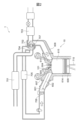
- FIG. 1 is a diagram showing a schematic configuration of an internal combustion engine having a fuel injection device.
- FIG. 2 is a diagram showing a schematic configuration of an internal combustion engine system including the internal combustion engine shown in FIG. 1 .
- 2 is a vertical sectional view of the fuel injection device shown in FIG. 1 and a diagram showing a schematic configuration of a control device.
- FIG. 4 is an enlarged view of the vicinity of the movable element and the valve body in FIG. 3 . 4 is a diagram showing the relationship between the injection pulse output from the ECU, the drive voltage applied to the solenoid of the fuel injection device, the drive current supplied to the solenoid, and the displacement amount of the valve body and the movable element.
- FIG. 1 is a diagram showing a schematic configuration of an internal combustion engine having a fuel injection device.
- FIG. 2 is a diagram showing a schematic configuration of an internal combustion engine system including the internal combustion engine shown in FIG. 1 .
- 2 is a vertical sectional view of the fuel injection device shown in FIG
- FIG. 5 is a diagram for explaining fuel injection control performed during operation in a catalyst warm-up mode.
- FIG. 3 is a projection diagram of a spray injected from a fuel injector.
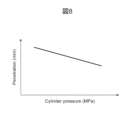
- 4 is a diagram showing the relationship between the penetration of the spray injected from the fuel injector and the pressure inside the cylinder.
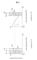
- FIG. FIG. 4 is a diagram for explaining a first embodiment of fuel injection control immediately before ignition timing performed during operation in a catalyst warm-up mode.
- FIG. 11 is a diagram for explaining a second embodiment of fuel injection control immediately before ignition timing performed during operation in a catalyst warm-up mode.
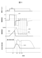
- FIG. 13 is a diagram showing the relationship between an injection pulse output from an ECU, a drive voltage applied to a solenoid of a fuel injection device, a drive current supplied to the solenoid, and a displacement amount of a valve body in the second embodiment.
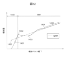
- FIG. FIG. 4 is a diagram showing the relationship between the injection pulse width and the injection amount of a fuel injection device.
- FIG. 4 is a diagram showing the relationship between the ignition retard amount, the fuel pressure, the injection amount, and the rotation speed of the internal combustion engine, and the elapsed time from the start of the internal combustion engine.
- FIG. 13 is a diagram for explaining a third embodiment of fuel injection control immediately before ignition timing performed during operation in a catalyst warm-up mode.
- FIG 1 is a diagram showing a schematic configuration of an internal combustion engine 10 having a fuel injection device 101.
- the internal combustion engine 10 is a direct injection type internal combustion engine that injects fuel directly into the cylinder 615.
- the internal combustion engine 10 includes a fuel injection device 101, a spark plug 604, an intake port 607, an exhaust port 608, a cylinder 614, a piston 609, an intake valve 605, and an exhaust valve 610.
- the spark plug 604 is disposed at the top center of the cylinder 614.
- the spark plug 604 has a negative electrode 612 and a positive electrode 613 exposed inside the cylinder 615.
- the fuel injection device 101 is a center injection type fuel injection device disposed near the spark plug 604 and injects fuel into the cylinder 615.
- the fuel injection device 101 may be a port injection type fuel injection device disposed in the intake port 607 and injects fuel into the intake port 607.
- the crown surface 606 of the piston 609 on the spark plug 604 side has a flat surface.
- a partition wall 602 is attached to the intake port 607 to block the flow between the upper part 620 and the lower part 611 of the intake port 607.
- a valve 601 is provided upstream of the partition wall 602, and the valve 601 is configured so that its opening and closing can be controlled by the control device 150.
- Figure 1 shows the valve 601 in a closed state.
- FIG. 1 illustrates intake valve 605 and exhaust valve 610.
- the intake valve 605 and exhaust valve 610 are not illustrated in a cross-sectional view passing through the central axis of cylinder 614.
- FIG. 1 also illustrates the state (D1 to D8) of the spray in cylinder 615 immediately after fuel is injected from fuel injection device 101.
- FIG. 2 is a diagram showing the schematic configuration of an internal combustion engine system 1 including the internal combustion engine 10 shown in FIG. 1.
- Air flowing into the cylinder 615 of the internal combustion engine 10 passes through an air cleaner 701, a turbocharger chamber 704 in which a turbocharger turbine 702 is installed, an intercooler 705, a throttle valve 706, and an intake port 607.
- the air cleaner 701 has the function of removing dust from the air and preventing it from being sucked into the cylinder 615, thereby suppressing wear on the cylinder 614 and piston 609.
- the turbocharging chamber 704 is provided with turbines 702 on the intake and exhaust sides, and by connecting them with a shaft 707, the turbines 702 rotate according to the flow speed of the exhaust gas, increasing the amount of air flowing into the cylinder 615 and improving output.
- the air that passes through the turbocharging chamber 704 is cooled by the intercooler 705, as its temperature increases due to supercharging by the turbine 702.
- the cooled air passes through a throttle valve 706, which adjusts the amount of air, and the intake port 607 before flowing into the cylinder 615.
- the air that flows into the cylinder 615 mixes with the fuel injected from the fuel injector 101 to form a mixture that is ignited by the spark plug 604 and combusted. This combustion pushes the piston 609 down, and after the driving force of the piston 609 is transmitted to the crankshaft 710, the exhaust valve 610 opens.
- the exhaust gas in the cylinder 615 passes through the exhaust port 608, and rotates the turbine 702 at the flow rate of the exhaust gas, while passing through the catalytic device 703.
- the exhaust gas passes through the catalytic device 703, where HC, NOx, and CO are reduced, and the exhaust gas is discharged outside the vehicle.
- the catalytic device 703 is, for example, composed of a three-way catalyst.
- the catalytic device 703 removes the HC, NOx, and CO contained in the exhaust gas by causing reduction and oxidation reactions with a catalyst using palladium, rhodium, platinum, or the like.
- the catalytic device 703 has low reduction ability when the catalyst temperature is low. In particular, under low temperature conditions, such as when the internal combustion engine 10 is started, combustion is required to warm up the catalyst quickly.
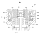
- FIG. 3 is a vertical cross-sectional view of the fuel injection device 101 shown in FIG. 1 and a diagram showing the schematic configuration of the control device 150.
- FIG. 4 is an enlarged view of the vicinity of the movable element 202 and the valve body 214 in FIG. 3.
- the fuel injection of the fuel injection device 101 is controlled by an injection pulse output from an engine control unit (ECU) 104.
- the ECU 104 is equipped with an A/D converter and an I/O port for receiving signals from various sensors.
- the ECU 104 receives signals indicating the state of the internal combustion engine 10 from the various sensors, and calculates the pulse width of the injection pulse (injection pulse width) for controlling the amount of fuel injection, as well as the start and end timings of the fuel injection, according to the operating conditions or operating mode of the internal combustion engine 10.
- the injection pulse output from the ECU 104 is input to the drive circuit 103 through a signal line 110.
- the drive circuit 103 determines the drive current waveform to be supplied to the solenoid 205 of the fuel injection device 101 based on a command from the ECU 104, and supplies the drive current waveform to the solenoid 205 of the fuel injection device 101 for a period of time based on the injection pulse.
- the ECU 104 communicates with the drive circuit 103 through a communication line 111.
- the ECU 104 can switch the drive current waveform determined by the drive circuit 103 and change the current and time settings depending on the fuel pressure supplied to the fuel injection device 101 and the operating conditions or operating mode of the internal combustion engine 10.
- the drive circuit 103 may be implemented as a component or board integrated with the ECU 104. In this embodiment, the drive circuit 103 and the ECU 104 are collectively referred to as the "control device 150."
- the fuel injection device 101 is a normally closed solenoid valve (electromagnetic fuel injection device). As shown in FIG. 3, the fuel injection device 101 has a valve body 214 that closes or opens a fuel injection hole 219 through which fuel is injected.
- the solenoid 205 When the solenoid 205 is not energized, the valve body 214 is biased in the valve closing direction (downward in FIG. 3) by the spring 210, which is a first spring, and is in close contact with the valve seat 218 to be in a closed state. In the closed state, the force of the return spring 212, which is a second spring, acts on the movable element 202 in the valve opening direction (upward in FIG. 3).
- the force of the spring 210 acting on the valve element 214 is greater than the force of the return spring 212, so that the end face 302 of the movable element 202 comes into contact with the valve element 214, and the movable element 202 is stationary, as shown in FIG. 4.
- the valve body 214 and the movable element 202 are configured to be relatively displaceable and are contained within the nozzle holder 201.
- the nozzle holder 201 has an end surface 303 that serves as a spring seat for the return spring 212.
- the force of the spring 210 is adjusted during assembly by the amount of pressure applied to the spring retainer 224 that is fixed to the inner surface of the stator (core) 207.
- the fuel injection device 101 forms a magnetic circuit with the stator 207, the movable element 202, the nozzle holder 201, and the housing 203.
- a gap 301 is provided between the movable element 202 and the stator 207.
- a magnetic restriction 211 is formed in a portion of the nozzle holder 201 corresponding to the gap 301 between the movable element 202 and the stator 207.
- the solenoid 205 is attached to the outer periphery of the nozzle holder 201 while being wound around the bobbin 204.
- a rod guide 215 is provided near the tip of the valve body 214 on the valve seat 218 side so as to be fixed to the nozzle holder 201.
- valve body 214 The movement of the valve body 214 in the valve axis direction (up and down direction in FIG. 3) is guided by two sliding points, the stator 207 that contacts the spring seat 304 of the valve body 214, and the rod guide 215.
- An orifice 216 with a valve seat 218 and a fuel injection hole 219 is fixed to the tip of the nozzle holder 201, sealing the internal space (fuel passage) between the movable element 202 and the valve body 214 from the outside.
- the fuel supplied to the fuel injection device 101 is supplied from a rail piping provided upstream of the fuel injection device 101 and flows through the fuel passage hole 231 to the tip of the valve body 214, where the fuel is sealed by the tip of the valve body 214 on the valve seat 218 side and the valve seat 218.
- a pressure difference is generated between the top and bottom of the valve body 214 due to the fuel pressure, and the valve body 214 is pushed in the valve closing direction by the pressure difference calculated by multiplying the fuel pressure by the pressure-receiving area of the inner diameter at the position of the valve seat 218, and the force of the spring 210.
- the movable element 202 moves to the position of the stator 207 and collides with the stator 207. After the movable element 202 collides with the stator 207, it bounces back due to the reaction force from the stator 207, but the magnetic attraction force acting on the movable element 202 causes the movable element 202 to be attracted to the stator 207 and eventually stops. At this time, a force is acting on the movable element 202 in the direction of the stator 207 by the return spring 212, so the time until the bound converges can be shortened. Because the bound is small, the time during which the gap 301 between the movable element 202 and the stator 207 becomes large is shortened, and stable operation can be performed even for smaller injection pulse widths.
- the movable element 202 and valve body 214 are stationary in the open valve state.
- a gap is created between the valve body 214 and the valve seat 218, and fuel is injected from the fuel injection hole 219.
- the fuel flows downstream through a central hole in the stator 207 and a fuel passage hole 305 in the movable element 202.
- the solenoid 205 When the solenoid 205 is de-energized, the magnetic flux generated in the magnetic circuit disappears, and the magnetic attraction force also disappears. As the magnetic attraction force acting on the movable member 202 disappears, the movable member 202 and the valve body 214 are pushed back toward the closed position in contact with the valve seat 218 by the force of the spring 210 and the differential pressure.
- valve body 214 moves from an open state to a closed state, the valve body 214 comes into contact with the valve seat 218, and then the movable element 202 moves away from the valve body 214 and the stator 207 in the valve closing direction, and after moving for a certain period of time, is returned to the initial position of the closed state by the return spring 212.
- the movable element 202 separates from the valve body 214. This allows the fuel injection device 101 to reduce the mass of the movable member at the moment when the valve body 214 collides with the valve seat 218 by the mass of the movable element 202. Therefore, the fuel injection device 101 can reduce the collision energy when colliding with the valve seat 218, and can suppress the bounding of the valve body 214 caused by the valve body 214 colliding with the valve seat 218.
- relative displacement occurs between the valve body 214 and the moving element 202 at the moment when the moving element 202 and the stator 207 collide when the valve is opened, and at the moment when the valve body 214 and the valve seat 218 collide when the valve is closed. This allows the fuel injection device 101 to suppress bounding of the moving element 202 against the stator 207 and bounding of the valve body 214 against the valve seat 218.
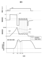
- Figure 5 shows the relationship between the injection pulse output from the ECU 104, the drive voltage applied to the solenoid 205 of the fuel injection device 101, the drive current supplied to the solenoid 205, and the amount of displacement of the valve body 214 and the movable element 202.
- the drive circuit 103 When an injection pulse is input to the drive circuit 103, the drive circuit 103 applies a high voltage 401 from a voltage source VH, which is boosted to a voltage higher than the battery voltage VB, to the solenoid 205, and starts supplying a drive current to the solenoid 205.
- the drive circuit 103 stops applying the high voltage 401. Then, due to the back electromotive force caused by the inductance of the solenoid 205, the drive current supplied to the solenoid 205 is fed back to the voltage source VH side, and rapidly drops from the peak current value Ipeak as in current 402.
- the drive circuit 103 applies the battery voltage VB to the solenoid 205, and controls it so that a predetermined current 403 is maintained.
- the differential pressure acting on the valve body 214 increases, and the time it takes for the valve body 214 to reach the target opening becomes longer. As a result, the timing of reaching the target opening may be delayed relative to the time it takes for the peak current value Ipeak to be reached. If the drive current is rapidly reduced to current 402, the magnetic attraction force acting on the movable element 202 also rapidly decreases, causing the behavior of the valve body 214 to become unstable, and in some cases, the valve may start to close even while current is still flowing.
- the drive circuit 103 causes the current generated by the back electromotive force to flow to the ground potential side, causing the current to regenerate within the circuit, the applied voltage of the solenoid 205 to become approximately 0 V, and the current 402 to gradually decrease.
- This allows the drive circuit 103 to gradually decrease the magnetic attraction force acting on the movable element 202, and stabilize the behavior of the valve body 214 at high fuel pressures. Therefore, the drive circuit 103 can suppress variations in the injection amount.
- the fuel injection device 101 is driven by such a driving current profile.
- the movable element 202 and the valve element 214 start to displace at timing t41. Thereafter, the movable element 202 and the valve element 214 reach a predetermined maximum height position.
- the movable element 202 collides with the stator 207 and bounds. Since the valve element 214 is configured to be displaceable relative to the movable element 202, it separates from the movable element 202, and the displacement of the valve element 214 overshoots beyond the maximum height position.
- the movable element 202 is displaced in the valve opening direction by the magnetic attraction force generated by the current 403 and the force of the return spring 212 in the valve opening direction, and comes to rest at the maximum height position at timing t44.
- the valve body 214 seats on the movable element 202 and displaces in the valve opening direction, and at timing t44, it comes to rest at the maximum height position and enters the open valve state.
- the amount of displacement of the valve body 214 does not exceed the maximum height position, and the amount of displacement of the movable element 202 and the valve body 214 after reaching the maximum height position (after timing t42) is equal.
- the height positions of the valve body 214 and the movable element 202 refer to the positions of the valve body 214 and the movable element 202 in the valve opening direction from the reference position, which is the position of the valve body 214 and the movable element 202 in the closed valve state where the valve body 214 is seated on the valve seat 218.
- the displacement amount of the valve body 214 and the movable element 202 is the displacement amount of the valve body 214 and the movable element 202 from the reference position.
- the maximum height position of the valve body 214 and the movable element 202 is determined in advance by the position of the stator 207 with which the movable element 202 collides.
- the displacement amount of the valve body 214 is also referred to as the lift amount of the valve body 214.
- the displacement amount of the valve body 214 when the valve body 214 reaches the maximum height position is also referred to as the maximum lift amount.
- Figure 6 is a diagram explaining the fuel injection control performed when operating in catalyst warm-up mode.
- the horizontal axis of FIG. 6 represents the angle of the crankshaft 710.
- the angle of the crankshaft 710 at the top dead center (TDC) of the piston 609 during the intake stroke is -360 degrees
- the angle of the crankshaft 710 at the bottom dead center (BDC) of the piston 609 is -180 degrees
- the angle of the crankshaft 710 at the TDC of the piston 609 during the compression stroke is 0 degrees.
- the dotted line in FIG. 6 represents the lift amount of the intake valve 605.
- the dashed line in FIG. 6 represents the average value of the turbulence velocity in the cylinder 615.
- the solid line in FIG. 6 represents the tumble in the cylinder 615.
- the shaded portion in FIG. 6 represents the period during which fuel injection is performed.
- the control device 150 controls the fuel injection device 101 to perform multiple fuel injections during one combustion cycle. At this time, the control device 150 may control the fuel injection device 101 to perform two or more fuel injections during the intake stroke 802 and one or more fuel injections during the expansion stroke 804. In the example of FIG. 6, the control device 150 controls the fuel injection device 101 to perform two fuel injections during the intake stroke 802 and one fuel injection during the expansion stroke 804. In the example of FIG. 6, the control device 150 performs ignition retard to retard the ignition timing to timing t86 within the expansion stroke 804. The ignition timing t86 changes depending on the timing of the catalyst temperature increase request and the environmental conditions, and is set in advance. The control device 150 needs to control the fuel injection device 101 to perform appropriate fuel injection for the desired ignition timing t86.
- control device 150 starts opening intake valve 605 to allow air to flow into cylinder 615.
- control device 150 starts a first fuel injection 805.
- control device 150 starts a second fuel injection 806.
- control device 150 starts a third fuel injection 807 at timing t84 immediately before ignition timing t86.
- the control device 150 controls the start timing t84 and end timing t85 of the fuel injection so that the spray injected from the fuel injection device 101 forms a rich mixture around the spark plug 604 that is richer in fuel than the theoretical air-fuel ratio (stoichiometric).
- the control device 150 sets the fuel split ratio between the intake stroke 802 and the expansion stroke 804 so that the intake stroke 802 has more fuel.
- the control device 150 may set the intake stroke 802:expansion stroke 804 ratio to about 6:4, 7:3, 8:2, or 9:1.
- the control device 150 performs ignition to ignite the mixture.
- the control device 150 controls the fuel injection device 101 so that the more the ignition timing t86 is delayed, the shorter the period from the end timing t85 of the fuel injection immediately before the ignition timing t86 to the ignition timing t86 becomes.
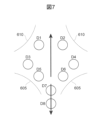
- Figure 7 is a projection of the spray injected from the fuel injection device 101.
- Figure 7 shows a projection of the spray when the A-A' cross section of the spray shown in Figure 1 is viewed in the direction toward the fuel injection device 101.
- the fuel injection device 101 is a multi-hole type fuel injection device in which the fuel injection hole 219 is composed of multiple holes.
- the spray injected from the fuel injection device 101 is composed of eight sprays, for example: sprays D1 and D2 injected toward the spark plug 604, sprays D3 and D4 injected toward the piston 609, and sprays D5 to D8 injected toward the intake valve 605 side of sprays D3 and D4.
- the concept of this embodiment is that, in the fuel injection just before the ignition timing, the sprays D1 and D2 form an air-fuel mixture between and around the negative electrode 612 and positive electrode 613 of the spark plug 604.
- the fuel injection device 101 injects the sprays D1 and D2 so that the sprays D1 and D2 are positioned between the negative electrode 612 and the positive electrode 613. This allows the fuel injection device 101 to form a mixture richer than stoichiometric between and around the negative electrode 612 and the positive electrode 613, ensuring combustion stability.
- Figure 8 shows the relationship between the penetration of the spray injected from the fuel injection device 101 and the pressure inside the cylinder 615.
- the spray injected from the fuel injection device 101 is susceptible to changes in spray penetration due to changes in pressure inside the cylinder 615. As shown in FIG. 8, the lower the pressure inside the cylinder 615, the longer the spray penetration. When the spray penetration is longer, the spray is more likely to diffuse inside the cylinder 615, making it difficult to maintain the mixture around the spark plug 604 at the ignition timing.
- FIG. 9 is a diagram illustrating a first embodiment of fuel injection control immediately before ignition timing performed when operating in catalyst warm-up mode.
- FIG. 9(a) shows a case where the ignition retard amount is small
- FIG. 9(b) shows a case where the ignition retard amount is large.
- the dashed line in FIG. 9 represents the pressure inside the cylinder 615.
- the load on the internal combustion engine 10 when operating in catalyst warm-up mode is the same.
- the amount of ignition retard is the amount by which the ignition timing is retarded from the optimal ignition timing that provides the best fuel economy. The greater the amount of ignition retard, the more the ignition timing is retarded.
- the control device 150 lengthens the fuel injection period 901, i.e., increases the injection amount, thereby increasing the penetration force of the spray and making it easier for the spray to diffuse inside the cylinder 615. This makes it easier for the control device 150 to maintain the mixture around the spark plug 604 at the ignition timing t93.
- the control device 150 shortens the fuel injection period 902, i.e., reduces the injection amount, thereby reducing the penetration force of the spray and suppressing the diffusion of the spray. This makes it easier for the control device 150 to maintain the mixture around the ignition plug 604 at the ignition timing t96. As a result, the control device 150 can stably ignite the mixture, ensuring combustion stability.
- the penetration of the spray tends to be long, so the fuel tends to adhere to the piston 609 and the wall surface inside the cylinder 615, and the PN tends to increase.
- the control device 150 reduces the injection amount, so it is possible to suppress the adhesion of fuel to the piston 609, etc., and therefore the PN can be suppressed.
- control device 150 controls the fuel injection device 101 so that the amount of fuel injected immediately before the ignition timing is reduced as the ignition timing is retarded. This allows the control device 150 to maintain the air-fuel mixture around the spark plug 604 at the ignition timing, and also suppress fuel adhesion to the piston 609, etc. Therefore, the control device 150 can ensure both combustion stability and PN suppression.
- the control device 150 may perform control to keep the air-fuel ratio stoichiometric or constant by adjusting the amount of fuel injected during the intake stroke. Specifically, when the amount of fuel injected immediately before the ignition timing during the expansion stroke is reduced because the ignition retard amount is large, the control device 150 controls the fuel injection device 101 so that the amount of fuel injected during the intake stroke increases in response to the reduction in the injection amount. In this way, the control device 150 can reliably ensure combustion stability by suppressing PN and keeping the air-fuel ratio stoichiometric or constant.
- the control device 150 may control the fuel injection device 101 so that the injection amount of the second and subsequent fuel injections during the intake stroke is increased.
- the control device 150 may lengthen the fuel injection period or increase the injection pulse width so that the injection amount of the second and subsequent fuel injections during the intake stroke (e.g., fuel injection 806 in FIG. 6) is increased by the amount that the injection amount immediately before the ignition timing during the expansion stroke is reduced.
- the fuel injection in the second intake stroke (e.g. fuel injection 806 in FIG. 6) is less likely to cause the mixture to diffuse. Therefore, increasing the amount of fuel injection in the second intake stroke can further increase the effect of forming a rich mixture over a wide area in the cylinder 615 and ensuring combustion stability. Also, compared to the first fuel injection in the intake stroke, the fuel injection in the second intake stroke has a slower injection timing, so the time it takes for the air and fuel to mix is longer, making it more difficult for the air and fuel to mix. Therefore, increasing the amount of fuel injection in the second intake stroke can further increase the effect of forming a rich mixture over a wide area around the spark plug 604 and ensuring combustion stability.
- FIG. 10 is a diagram illustrating a second embodiment of fuel injection control immediately before ignition timing performed when operating in catalyst warm-up mode.
- FIG. 10(a) shows a case where the ignition retard amount is small
- FIG. 10(b) shows a case where the ignition retard amount is large.
- the dashed line in FIG. 10 represents the pressure inside the cylinder 615.
- the load on the internal combustion engine 10 when operating in catalyst warm-up mode is the same.
- the control device 150 according to the second embodiment performs the following fuel injection control in addition to the fuel injection control according to the first embodiment, which controls the fuel injection device 101 so that the amount of fuel injected immediately before the ignition timing is reduced as the ignition retard amount increases. That is, the control device 150 according to the second embodiment controls the fuel injection device 101 so that the period from the end timing of the fuel injection immediately before the ignition timing to the ignition timing is shortened as the ignition retard amount increases, i.e., the ignition timing is retarded. Specifically, the control device 150 controls so that the period 1202 is shortened when the ignition retard amount is large, compared to the period 1201 from the end timing t23 of the fuel injection to the ignition timing t93 when the ignition retard amount is small.
- the control device 150 according to the second embodiment can form a stable rich mixture around the ignition plug 604 and ensure combustion stability by shortening the period 1202 from the fuel injection end timing t25 to the ignition timing t96 as the ignition retard amount increases. However, if the period 1202 is made too short, the fuel injection end timing t25 approaches the ignition timing t96, shortening the time for the spray to vaporize, and there is a possibility that the mixture will ignite before the spray has finished vaporizing. However, the control device 150 according to the second embodiment can shorten the time required for the spray to vaporize by reducing the injection amount, thereby suppressing fuel adhesion to the piston 609, etc. at the ignition timing t96, and can suppress PN while ensuring combustion stability. Furthermore, by suppressing an extremely rich mixture, for example, with an equivalence ratio of 2 or more, it is possible to further suppress PN.
- FIG. 11 is a diagram showing the relationship between the injection pulse output from the ECU 104, the drive voltage applied to the solenoid 205 of the fuel injection device 101, the drive current supplied to the solenoid 205, and the amount of displacement of the valve body 214 in the second embodiment.
- FIG. 11 corresponds to FIG. 5.
- the dashed lines in FIG. 11 show the waveforms in the first embodiment shown in FIG. 5, and the solid lines in FIG. 11 show the waveforms in the second embodiment.
- the control device 150 controls the valve element 214 so that the valve element 214 operates with the displacement transition 1301 shown in FIG. 11 during fuel injection immediately before the ignition timing. That is, the control device 150 controls the valve element 214 so that the valve element 214 displaces within a range of height positions lower than the maximum height position during fuel injection immediately before the ignition timing. In other words, the control device 150 according to the second embodiment controls the lift amount of the valve element 214 during fuel injection immediately before the ignition timing within a range smaller than a predetermined maximum lift amount.
- the control device 150 then controls the fuel injection device 101 so that the lift amount of the valve body 214 becomes smaller as the ignition retard amount becomes larger, i.e., the more the ignition timing is retarded.
- the lift amount of the valve body 214 By reducing the lift amount of the valve body 214, the pressure loss of the fuel flowing between the valve body 214 and the valve seat 218 increases, and the flow rate of the spray becomes slower. Therefore, even if the ignition timing is retarded and the pressure inside the cylinder 615 is low at the timing of fuel injection, it is possible to easily form an air-fuel mixture near the spark plug 604, and combustion stability can be ensured.
- the control device 150 reduces the lift amount of the valve body 214 as the ignition retard amount increases, but when the ignition retard amount is small, the control device 150 may control the valve body 214 to reach its maximum height position. As a result, the upper limit value of the lift amount of the valve body 214 can be changed significantly depending on the ignition retard amount, making it easier to maintain the mixture around the spark plug 604 in response to changes in the pressure inside the cylinder 615 that change depending on the ignition retard amount.
- FIG. 12 shows the relationship between the injection pulse width Ti and the injection amount of the fuel injection device 101.
- FIG. 12 shows the injection amount characteristic Q141 when each waveform shown in FIG. 11 is used.
- the valve body 214 does not start opening and fuel is not injected.
- the force in the valve opening direction which is the resultant force of the magnetic attractive force acting on the movable member 202 and the return spring 212, does not exceed the force of the spring 210, the valve body 214 does not start opening and fuel is not injected.
- the movable member 202 starts to displace, if the magnetic attractive force required for sliding through the gap 301 cannot be secured and the movable member 202 does not come into contact with the valve body 214, the valve body 214 does not start opening and fuel is not injected.
- the movable member 202 collides with the valve body 214, and the valve body 214 moves away from the valve seat 218 and starts to displace.
- the injection amount is less than the dashed line 1420, which is extrapolated from the linear region 1430 where the relationship between the injection pulse width Ti and the injection amount is approximately linear.
- the valve element 214 starts to close immediately after reaching the maximum height position, and the trajectory of the valve element 214 becomes parabolic.
- the kinetic energy of the valve element 214 in the valve opening direction is large, and the magnetic attraction force acting on the movable element 202 is large, so the proportion of the time required to close the valve increases, and the injection amount is greater than that of the dashed line 1420.
- the region 1440 where the movable element 202 does not collide with the stator 207, i.e., where the valve element 214 does not reach the maximum height position and the trajectory of the valve element 214 becomes parabolic is also referred to as the "half lift region 1440.”
- the region 1441 where the movable element 202 collides with the stator 207, i.e., where the valve element 214 reaches the maximum height position is also referred to as the "full lift region 1441.”
- the solid line in FIG. 11 shows the case where the valve element 214 is displaced in the half lift region 1440.
- the valve starts to close at the timing when the amount of bouncing of the valve body 214 caused by the movable element 202 colliding with the stator 207 is at its maximum.
- the repulsive force generated when the movable element 202 and the stator 207 collide acts on the movable element 202, and the valve closing delay time from when the injection pulse is turned OFF until the valve body 214 closes is reduced.
- the injection amount is less than the dashed line 1420.
- the injection pulse width Ti at point 1404 is the case where the valve starts to close immediately after the bound of the valve body 214 has converged.
- the injection amount increases approximately linearly with the increase in injection pulse width Ti.
- the valve body 214 does not reach the maximum height position, or even if the valve body 214 reaches the maximum height position, the bound of the valve body 214 is not stable, so the injection amount fluctuates.
- Fuel injection immediately before the ignition timing during the expansion stroke has a large effect on combustion stability if the injection amount fluctuates. Therefore, the control device 150 may adjust the injection pulse width Ti so that the valve body 214 is displaced in the half lift region 1440 or the linear region 1430. As a result, the control device 150 can more easily ensure combustion stability.
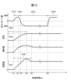
- FIG. 13 is a diagram showing the relationship between the ignition retard amount, fuel pressure, injection amount, and internal combustion engine 10 rotation speed, and the time elapsed since the start of internal combustion engine 10.
- the ignition retard amount when the ignition retard amount is 0, this indicates a case where the ignition timing is set to the TDC timing of the compression stroke.
- the ignition retard amount when the ignition retard amount is retarded, this indicates a case where the ignition timing is set to the retard side of the TDC of the compression stroke.
- the ignition retard amount is advanced, this indicates a case where the ignition timing is set to the advanced side of the TDC of the compression stroke.
- the control device 150 sets the ignition retard amount to the advance side (the ignition timing is more advanced than the TDC of the compression stroke) to achieve stable combustion and increase the temperature inside the cylinder 615.
- the control device 150 shifts the ignition retard amount to the retard side (the ignition timing is more advanced than the TDC of the compression stroke) to increase exhaust loss and increase the temperature of the exhaust gas discharged from the inside of the cylinder 615 to the exhaust port 608.
- the control device 150 can activate the catalyst of the catalytic device 703 early and reduce HC.
- the transition period 1502 until the ignition retard amount shifts to the retard side, and the operation period 1503 in the catalyst warm-up mode, which is the period after the ignition retard amount shifts to the retard side there is a transient period 1504 during which the fuel pressure (hereinafter also referred to as "fuel pressure") supplied to the fuel injection device 101 changes (rises).
- the fuel pump that supplies high-pressure fuel to the fuel injection device 101 supplies high-pressure fuel to a fuel pipe communicating with the fuel injection device 101 by the compression operation of a plunger synchronized with the camshaft of the internal combustion engine 10. Therefore, when the rotation speed of the internal combustion engine 10 is low, a certain amount of time is required for the fuel pressure to reach the target pressure 1505.
- a transient period 1504 during which the fuel pressure changes occurs between the start timing t51 of the internal combustion engine 10 and the timing t56 at which the catalyst warm-up ends.
- the internal combustion engine 10 starts and stops more frequently than in vehicles equipped with only the internal combustion engine 10, so the fuel pressure when the internal combustion engine 10 starts changes frequently.
- FIG. 14 is a diagram explaining a third embodiment of fuel injection control immediately before ignition timing performed when operating in catalyst warm-up mode.
- FIG. 14(a) shows the case where the fuel pressure is low
- FIG. 14(b) shows the case where the fuel pressure is high.
- the ignition retard amount is the same in FIG. 14(a) and FIG. 14(b).
- the spray penetration power is small, so the spray is less likely to diffuse within the cylinder 615.
- the spray penetration power is large, so the spray is more likely to diffuse within the cylinder 615. Therefore, when the fuel pressure changes, it is desirable to adjust at least one of the injection amount and the end timing of the fuel injection immediately before the ignition timing.
- the control device 150 controls the fuel injection device 101 so that the lower the fuel pressure supplied to the fuel injection device 101 at the start timing of the fuel injection immediately before the ignition timing, the longer the period from the end timing of the fuel injection immediately before the ignition timing to the ignition timing. Furthermore, the control device 150 controls the fuel injection device 101 so that the injection amount of the fuel injection immediately before the ignition timing becomes larger as the fuel pressure is lower.
- the control device 150 controls the period 1601 from the end timing t65 of the fuel injection to the ignition timing t66 to be longer when the fuel pressure is low, compared to the period 1602 from the end timing t65 of the fuel injection to the ignition timing t66 when the fuel pressure is high. This allows the control device 150 to make the spray more easily diffused in the cylinder 615, making it easier for the mixture to reach the area around the spark plug 604 and ensuring combustion stability. Furthermore, the control device 150 controls the fuel injection period 906 to be longer when the fuel pressure is low, compared to the fuel injection period 907 when the fuel pressure is high. This allows the control device 150 to increase the penetration force of the spray to make it easier to diffuse, making it easier for the mixture to reach the area around the spark plug 604 and further ensuring combustion stability.
- control device 150 controls the fuel injection device 101 so that the injection amount of the fuel injection immediately before the ignition timing decreases as the fuel pressure supplied to the fuel injection device 101 at the start timing of the fuel injection immediately before the ignition timing increases. Furthermore, the control device 150 controls the fuel injection device 101 so that the period from the end timing of the fuel injection immediately before the ignition timing to the ignition timing decreases as the fuel pressure increases.
- the control device 150 controls the fuel injection period 907 to be shorter than the fuel injection period 906 when the fuel pressure is low.
- the control device 150 can reduce the penetration force of the spray and suppress the diffusion of the spray, thereby suppressing fuel adhesion to the piston 609, etc., and suppressing PN while ensuring combustion stability.
- the control device 150 controls the period 1602 to be shorter than the period 1601 from the end timing t62 of the fuel injection to the ignition timing t63 when the fuel pressure is low.
- control device 150 can make it difficult for the spray to diffuse in the cylinder 615, make it easier to maintain the mixture around the ignition plug 604, and suppress fuel adhesion to the piston 609, etc., so that it is possible to achieve a high degree of both ensuring combustion stability and suppressing PN.
- control device 150 can adjust at least one of the end timing and injection amount of the fuel injection just before the ignition timing in response to changes in fuel pressure, so that a mixture can be formed around the spark plug 604 even if the fuel pressure changes, and combustion stability can be ensured.
- adjusting both can greatly control the diffusion state of the spray inside the cylinder 615, thereby ensuring combustion stability and further enhancing the effect of PN suppression.
- the control device 150 is particularly effective when applied to a hybrid vehicle, and can further enhance the effects of ensuring combustion stability and suppressing PN in the hybrid vehicle.
- the present invention is not limited to the above-described embodiments, and includes various modified examples.
- the above-described embodiments have been described in detail to clearly explain the present invention, and are not necessarily limited to those having all of the configurations described. It is also possible to replace part of the configuration of one embodiment with the configuration of another embodiment, and it is also possible to add the configuration of another embodiment to the configuration of one embodiment. It is also possible to add, delete, or replace part of the configuration of each embodiment with other configurations.
- each of the above configurations, functions, processing units, or processing means, etc. may be realized in part or in whole by hardware, for example by designing them as integrated circuits. Furthermore, each of the above configurations or functions, etc. may be realized by software, in which a processor interprets and executes a program that realizes each function. Information such as the programs, tables, or files that realize each function can be stored in a recording device such as a memory, a hard disk, or an SSD (solid state drive), or in a recording medium such as an IC card, an SD card, or a DVD.
- a recording device such as a memory, a hard disk, or an SSD (solid state drive)
- a recording medium such as an IC card, an SD card, or a DVD.
- control lines and information lines shown are those considered necessary for the explanation, and do not necessarily show all control lines and information lines on the product. In reality, it can be assumed that almost all components are interconnected.
Landscapes
- Engineering & Computer Science (AREA)
- Chemical & Material Sciences (AREA)
- Combustion & Propulsion (AREA)
- Mechanical Engineering (AREA)
- General Engineering & Computer Science (AREA)
- Electrical Control Of Air Or Fuel Supplied To Internal-Combustion Engine (AREA)
Abstract
Description
上記以外の課題、構成及び効果は、以下の実施形態の説明により明らかにされる。
図1~図9を用いて、実施形態1に係る燃料噴射装置101の制御装置150について説明する。図1は、燃料噴射装置101を有する内燃機関10の概略構成を示す図である。
図10~図12を用いて、実施形態2に係る燃料噴射装置101の制御装置150について説明する。実施形態2に係る燃料噴射装置101の制御装置150において、実施形態1と同様の構成及び動作については、説明を省略する。
図13及び図14を用いて、実施形態3に係る燃料噴射装置101の制御装置150について説明する。実施形態3に係る燃料噴射装置101の制御装置150において、実施形態1,2と同様の構成及び動作については、説明を省略する。
Claims (6)
- 点火タイミングを膨張行程まで遅角する点火リタードによって触媒を暖機する触媒暖機モードで運転する内燃機関の気筒内に燃料を直接噴射する燃料噴射装置の制御装置であって、
前記触媒暖機モードでの運転時、1燃焼サイクル中に行われる複数回の燃料噴射のうち前記点火タイミング直前の前記燃料噴射を前記膨張行程において行うと共に、前記点火タイミングが遅角するほど、前記点火タイミング直前の前記燃料噴射の噴射量が少なくなるよう、前記燃料噴射装置を制御する
ことを特徴とする燃料噴射装置の制御装置。 - 前記点火タイミングが遅角するほど、前記点火タイミング直前の前記燃料噴射の終了タイミングから前記点火タイミングまでの期間が短くなるよう、前記燃料噴射装置を制御する
ことを特徴とする請求項1に記載された燃料噴射装置の制御装置。 - 吸気行程において2回以上の燃料噴射を行うと共に、前記点火タイミング直前の前記燃料噴射の前記噴射量の減少に応じて、前記吸気行程において2回目以降に行われる前記燃料噴射の噴射量が増えるよう、前記燃料噴射装置を制御する
ことを特徴とする請求項1に記載された燃料噴射装置の制御装置。 - 前記燃料噴射装置は、前記燃料が噴射される燃料噴射孔を閉塞又は開放する弁体を有し、
前記制御装置は、前記点火タイミング直前の前記燃料噴射における前記弁体のリフト量を予め定められた最大リフト量より小さい範囲において制御し、前記点火タイミングが遅角するほど前記リフト量が小さくなるよう、前記弁体を制御する
ことを特徴とする請求項1に記載された燃料噴射装置の制御装置。 - 点火タイミングを膨張行程まで遅角する点火リタードによって触媒を暖機する触媒暖機モードで運転する内燃機関の気筒内に燃料を直接噴射する燃料噴射装置の制御装置であって、
前記触媒暖機モードでの運転時、1燃焼サイクル中に行われる複数回の燃料噴射のうち前記点火タイミング直前の前記燃料噴射を前記膨張行程において行うと共に、前記点火タイミング直前の前記燃料噴射の開始タイミングにおいて前記燃料噴射装置に供給される燃料圧力が高いほど、前記点火タイミング直前の前記燃料噴射の終了タイミングから前記点火タイミングまでの期間が短くなるよう、前記燃料噴射装置を制御する
ことを特徴とする燃料噴射装置の制御装置。 - 前記点火タイミング直前の前記燃料噴射の開始タイミングにおいて前記燃料圧力が高いほど、前記点火タイミング直前の前記燃料噴射の噴射量が少なくなるよう、前記燃料噴射装置を制御する
ことを特徴とする請求項5に記載された燃料噴射装置の制御装置。
Priority Applications (4)
| Application Number | Priority Date | Filing Date | Title |
|---|---|---|---|
| DE112023005119.4T DE112023005119T5 (de) | 2023-06-27 | 2023-06-27 | Steuervorrichtung für die Kraftstoffeinspritzvorrichtung |
| CN202380094530.4A CN120731316A (zh) | 2023-06-27 | 2023-06-27 | 燃料喷射装置的控制装置 |
| JP2025529042A JP7895011B2 (ja) | 2023-06-27 | 2023-06-27 | 燃料噴射装置の制御装置 |
| PCT/JP2023/023787 WO2025004178A1 (ja) | 2023-06-27 | 2023-06-27 | 燃料噴射装置の制御装置 |
Applications Claiming Priority (1)
| Application Number | Priority Date | Filing Date | Title |
|---|---|---|---|
| PCT/JP2023/023787 WO2025004178A1 (ja) | 2023-06-27 | 2023-06-27 | 燃料噴射装置の制御装置 |
Publications (1)
| Publication Number | Publication Date |
|---|---|
| WO2025004178A1 true WO2025004178A1 (ja) | 2025-01-02 |
Family
ID=93937894
Family Applications (1)
| Application Number | Title | Priority Date | Filing Date |
|---|---|---|---|
| PCT/JP2023/023787 Ceased WO2025004178A1 (ja) | 2023-06-27 | 2023-06-27 | 燃料噴射装置の制御装置 |
Country Status (4)
| Country | Link |
|---|---|
| JP (1) | JP7895011B2 (ja) |
| CN (1) | CN120731316A (ja) |
| DE (1) | DE112023005119T5 (ja) |
| WO (1) | WO2025004178A1 (ja) |
Citations (8)
| Publication number | Priority date | Publication date | Assignee | Title |
|---|---|---|---|---|
| JP2006052687A (ja) * | 2004-08-12 | 2006-02-23 | Nissan Motor Co Ltd | 筒内直接噴射式内燃機関 |
| JP2006112364A (ja) * | 2004-10-18 | 2006-04-27 | Nissan Motor Co Ltd | 筒内直接噴射式火花点火内燃機関の制御装置 |
| JP2006177179A (ja) * | 2004-12-21 | 2006-07-06 | Nissan Motor Co Ltd | 筒内直接噴射式火花点火内燃機関の制御装置 |
| JP2006283679A (ja) * | 2005-04-01 | 2006-10-19 | Nissan Motor Co Ltd | 筒内直接噴射式火花点火内燃機関の制御装置 |
| JP2007002796A (ja) * | 2005-06-27 | 2007-01-11 | Nissan Motor Co Ltd | 筒内直接噴射式火花点火内燃機関の制御装置 |
| WO2016194184A1 (ja) * | 2015-06-03 | 2016-12-08 | 日産自動車株式会社 | 内燃機関制御装置及び内燃機関制御方法 |
| JP2022014271A (ja) * | 2020-07-06 | 2022-01-19 | トヨタ自動車株式会社 | エンジン装置 |
| JP2022014634A (ja) * | 2020-07-07 | 2022-01-20 | トヨタ自動車株式会社 | エンジン装置 |
-
2023
- 2023-06-27 CN CN202380094530.4A patent/CN120731316A/zh active Pending
- 2023-06-27 JP JP2025529042A patent/JP7895011B2/ja active Active
- 2023-06-27 WO PCT/JP2023/023787 patent/WO2025004178A1/ja not_active Ceased
- 2023-06-27 DE DE112023005119.4T patent/DE112023005119T5/de active Pending
Patent Citations (8)
| Publication number | Priority date | Publication date | Assignee | Title |
|---|---|---|---|---|
| JP2006052687A (ja) * | 2004-08-12 | 2006-02-23 | Nissan Motor Co Ltd | 筒内直接噴射式内燃機関 |
| JP2006112364A (ja) * | 2004-10-18 | 2006-04-27 | Nissan Motor Co Ltd | 筒内直接噴射式火花点火内燃機関の制御装置 |
| JP2006177179A (ja) * | 2004-12-21 | 2006-07-06 | Nissan Motor Co Ltd | 筒内直接噴射式火花点火内燃機関の制御装置 |
| JP2006283679A (ja) * | 2005-04-01 | 2006-10-19 | Nissan Motor Co Ltd | 筒内直接噴射式火花点火内燃機関の制御装置 |
| JP2007002796A (ja) * | 2005-06-27 | 2007-01-11 | Nissan Motor Co Ltd | 筒内直接噴射式火花点火内燃機関の制御装置 |
| WO2016194184A1 (ja) * | 2015-06-03 | 2016-12-08 | 日産自動車株式会社 | 内燃機関制御装置及び内燃機関制御方法 |
| JP2022014271A (ja) * | 2020-07-06 | 2022-01-19 | トヨタ自動車株式会社 | エンジン装置 |
| JP2022014634A (ja) * | 2020-07-07 | 2022-01-20 | トヨタ自動車株式会社 | エンジン装置 |
Also Published As
| Publication number | Publication date |
|---|---|
| JP7895011B2 (ja) | 2026-07-24 |
| CN120731316A (zh) | 2025-09-30 |
| JPWO2025004178A1 (ja) | 2025-01-02 |
| DE112023005119T5 (de) | 2025-10-16 |
Similar Documents
| Publication | Publication Date | Title |
|---|---|---|
| JP5494205B2 (ja) | 自動車搭載用ディーゼルエンジン | |
| Tanabe et al. | Effect of fuel injection rate control on reduction of emissions and fuel consumption in a heavy duty DI diesel engine | |
| US8770174B2 (en) | Method and device for controlling diesel engine | |
| KR101235518B1 (ko) | 가변 밸브 구동 기구가 부착된 엔진 | |
| US20180340488A1 (en) | Method and system for controlling engine | |
| CN105358812B (zh) | 发动机控制装置 | |
| JP2011106444A (ja) | 圧縮着火ガソリンエンジン | |
| CN105324569B (zh) | 引擎控制装置 | |
| WO2018221157A1 (ja) | 燃料噴射制御装置 | |
| US7201145B2 (en) | Fuel supply apparatus for internal combustion engine | |
| JP2017517674A (ja) | Lpg直接噴射式エンジン | |
| JP2012246784A (ja) | 火花点火式エンジンの制御装置 | |
| JPH112133A (ja) | 筒内噴射エンジンの空気流動制御法および制御装置 | |
| JP2009216059A (ja) | 内燃機関の制御装置 | |
| CN109989841B (zh) | 用于操作燃料喷射器的系统和方法 | |
| JPH07310603A (ja) | エンジンの排気還流装置 | |
| JP7140548B2 (ja) | インジェクタの制御装置 | |
| JP2003106177A (ja) | 火花点火式直噴エンジン | |
| WO2021053935A1 (ja) | 燃料噴射制御装置及び燃料噴射制御方法 | |
| JP2005002967A (ja) | ターボ過給機付火花点火式直噴エンジンの制御装置 | |
| CN120731316A (zh) | 燃料喷射装置的控制装置 | |
| JPH1113594A (ja) | 燃料噴射ノズル | |
| WO2025134319A1 (ja) | 内燃機関の制御装置 | |
| JP3298371B2 (ja) | ディーゼルエンジンの制御装置 | |
| JP7727824B2 (ja) | 燃料噴射制御装置及び燃料噴射制御方法 |
Legal Events
| Date | Code | Title | Description |
|---|---|---|---|
| 121 | Ep: the epo has been informed by wipo that ep was designated in this application |
Ref document number: 23943578 Country of ref document: EP Kind code of ref document: A1 |
|
| WWE | Wipo information: entry into national phase |
Ref document number: 112023005119 Country of ref document: DE |
|
| ENP | Entry into the national phase |
Ref document number: 2025529042 Country of ref document: JP Kind code of ref document: A |
|
| WWE | Wipo information: entry into national phase |
Ref document number: 2025529042 Country of ref document: JP |
|
| WWE | Wipo information: entry into national phase |
Ref document number: 202380094530.4 Country of ref document: CN |
|
| WWP | Wipo information: published in national office |
Ref document number: 202380094530.4 Country of ref document: CN |
|
| WWP | Wipo information: published in national office |
Ref document number: 112023005119 Country of ref document: DE |
|
| 122 | Ep: pct application non-entry in european phase |
Ref document number: 23943578 Country of ref document: EP Kind code of ref document: A1 |