WO2025004153A1 - 劣化促進装置 - Google Patents
劣化促進装置 Download PDFInfo
- Publication number
- WO2025004153A1 WO2025004153A1 PCT/JP2023/023645 JP2023023645W WO2025004153A1 WO 2025004153 A1 WO2025004153 A1 WO 2025004153A1 JP 2023023645 W JP2023023645 W JP 2023023645W WO 2025004153 A1 WO2025004153 A1 WO 2025004153A1
- Authority
- WO
- WIPO (PCT)
- Prior art keywords
- test specimen
- test
- deterioration
- gear
- jig
- Prior art date
- Legal status (The legal status is an assumption and is not a legal conclusion. Google has not performed a legal analysis and makes no representation as to the accuracy of the status listed.)
- Ceased
Links
Images


Classifications
-
- G—PHYSICS
- G01—MEASURING; TESTING
- G01N—INVESTIGATING OR ANALYSING MATERIALS BY DETERMINING THEIR CHEMICAL OR PHYSICAL PROPERTIES
- G01N17/00—Investigating resistance of materials to the weather, to corrosion, or to light
Definitions
- This disclosure relates to a deterioration acceleration device.
- Non-Patent Document 1 Compared to inorganic compounds such as metals, ceramics, and glass, polymeric materials are prone to deterioration and have inferior durability. The deterioration of polymeric materials is influenced by three factors: "environmental conditions” such as ultraviolet light, heat, water, and chemicals; “mechanical conditions” such as tension, compression, bending, and impact; and “special conditions” such as electrical action (Non-Patent Document 1).
- environmental conditions such as ultraviolet light, heat, water, and chemicals
- mechanical conditions such as tension, compression, bending, and impact
- special conditions such as electrical action
- Non-Patent Document 2 discloses degradation behavior due to light and heat.
- Non-Patent Document 3 discloses degradation behavior due to infrared rays.
- Non-Patent Document 4 discloses degradation behavior due to bending stress.
- Non-Patent Document 5 deals with environmental stress cracking of plastics.
- This disclosure has been made in light of the above circumstances, and the purpose of this disclosure is to provide a technology that can efficiently promote the complex degradation of polymeric materials.
- the degradation acceleration device is an degradation acceleration device that accelerates the complex degradation of a polymeric material, and includes a refractable test specimen jig that holds a polymeric material test specimen, a rotating disk that revolves the test specimen jig around a light source, and a refraction mechanism that refracts the test specimen jig when the test specimen jig reaches one or more predetermined positions.
- This disclosure provides a technology that can efficiently promote the complex degradation of polymeric materials.
- FIG. 1 is a diagram showing an example of the configuration of a degradation promoting device.
- FIG. 2 is a cross-sectional view taken along the A-A' direction in FIG.
- FIG. 3 is a diagram showing an example of the configuration of a test specimen jig.
- FIG. 4 is a side view of FIG.
- FIG. 5 is a bottom view of FIG.
- FIG. 6 is a diagram showing an example of mounting the test specimen and the test specimen jig.
- FIG. 7 is a diagram showing the refraction state of the test specimen.
- FIG. 8 is a diagram illustrating an example of the configuration of the control device.
- FIG. 9 is a diagram showing an example of the operation of the degradation promotion device.
- FIG. 10 is a diagram showing an example of the operation of the degradation promotion device.
- FIG. 11 is a diagram illustrating an example of a hardware configuration of the control device.
- the present disclosure discloses a technique for promoting the composite degradation of a polymer material. Specifically, the composite degradation of the polymer material is promoted by applying environmental degradation factors including light simulating sunlight and repeated bending stress to the polymer material, and the degradation progress state of the polymer material is measured by image analysis and infrared spectroscopy.
- the bending mechanism that applies the bending stress uses the force that rotates the gears by meshing a pin rack fixed to the device with a gear on the polymer material side that revolves around the light source. This makes it possible to bend the polymer material easily and efficiently, and allows for easy evaluation of the resistance of the polymer material to the combined deterioration caused by light and bending. For example, by evaluating that the rate at which deterioration progresses differs depending on the bending angle and using the polymer material within a bending angle range where deterioration progresses least, it becomes possible to use the polymer material stably for a long period of time.
- a light source device exposes the polymeric material to environmental deterioration factors including light
- a pin rack and gears apply repeated bending stress to the polymeric material
- a control device measures the deterioration progress of the polymeric material based on image information of the polymeric material
- a control device and infrared spectroscopic analysis device measure the deterioration progress of the polymeric material based on the results of infrared spectroscopic analysis of the polymeric material.
- the degradation acceleration device is a device for accelerating the composite degradation of a polymeric material.
- the polymeric material is a plastic material that is flexible enough to be bent and is expected to be degraded by ultraviolet light. Examples of the polymeric material include polyethylene and polypropylene.
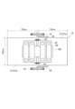
- FIG. 1 is a diagram showing the overall configuration of the degradation acceleration device according to this embodiment.
- FIG. 2 is a cross-sectional view of the inside of the accelerated degradation test chamber as seen from the A-A' direction shown in FIG. 1.
- FIG. 2 shows a simplified view of the meshing state between the pin rack 17 on the device side and the gear 19 on the polymer material specimen side.
- the degradation acceleration device comprises an accelerated degradation test chamber 1, a control device 2, and an infrared spectroscopic analysis device 3.
- the accelerated deterioration test tank 1 includes additional sections (light source 31, temperature regulator 32, humidity regulator 33) that apply environmental deterioration factors including light simulating sunlight to a polymer material test specimen 100, mechanical sections (rotation mechanism 51, refraction mechanisms 16, 17, 19) that apply repeated bending stresses, etc. to the test specimen 100, and an observation section (imaging section 71, measurement section 72) that observes the deterioration progression state of the test specimen 100.
- the accelerated deterioration test chamber 1 has a hollow rectangular parallelepiped shape and an airtight internal structure. Legs 4 are provided at the bottom of the accelerated deterioration test chamber 1. The accelerated deterioration test chamber 1 is supported by the legs 4 and placed on a flat floor surface.
- a support pillar 13 is installed inside the accelerated deterioration test chamber 1, connecting the center of the top plate 11 with the center of the bottom plate 12.
- An upper rotating disk 14 is connected to the top of the support pillar 13, a lower rotating disk 15 is connected to the bottom, and a fixed disk 16 is connected to a slightly lower position between them.
- a light source 31 is installed in the section of the support pillar 13 between the upper rotating disk 14 and the lower rotating disk 15.
- the light source 31 irradiates light simulating sunlight in the surrounding area (360° radial direction). That is, the light source 31 is installed in the center of each disk 14, 15, 16, and irradiates light onto multiple test specimens 100.
- the light source 31 irradiates light including light in the ultraviolet range onto the test specimens 100 present in the surrounding area.
- the light source 31 may also irradiate light in the visible range or infrared range.
- the light source 31 is, for example, an ultraviolet fluorescent lamp, a xenon lamp, a sunshine carbon lamp, or a metal halide lamp.
- the light source 31 may be a combination of such a lamp and a filter to make the spectral radiation distribution of the emitted light closer to that of sunlight.
- the light source 31 that can be used is one that performs tests conforming to "ISO 11341", “JIS K 5600-7-7", “JIS K 7350-2", etc.
- a temperature regulator 32 is provided on the inner side of the accelerated deterioration test chamber 1 to maintain the interior of the accelerated deterioration test chamber 1 at a predetermined temperature.
- a humidity regulator 33 is provided on the top surface of the upper rotating disk 14 to maintain the interior of the accelerated deterioration test chamber 1 at a predetermined humidity.
- the support 13 can be rotated by the rotation mechanism 51 around a part of its longitudinal direction as a rotation axis.
- the rotation mechanism 51 by controlling the rotation mechanism 51, the upper rotating disk 14 and the lower rotating disk 15 can be rotated around the support 13 as a central axis.
- the rotation mechanism 51 is equipped with, for example, a stepping motor, and can rotate the upper rotating disk 14 and the lower rotating disk 15 and stop them at a predetermined angle. By rotating each disk 14, 15, the rotation mechanism 51 controls the positioning of the multiple test specimens 100 in turn within the imaging range and measurement position of the imaging unit 71 and the measurement unit 72.
- the rotation speed of each disk 14, 15 (the time it takes for the test specimen 100 to complete one rotation) can be set arbitrarily.
- a fixed disk 16 is connected to the longitudinal side of this non-rotating support 13.
- the upper rotating disk 14 and the lower rotating disk 15 are rotating disks, but the fixed disk 16 is a non-rotating disk.
- a pin rack 17 is attached to the edge of the fixed disk 16 at one or more locations.
- the pin rack 17 is a tooth with an R-shape that follows the circular shape of the edge of the fixed disk 16.
- a bendable test specimen jig 18 that holds the test specimen 100 is attached to the upper surface of the lower rotating disk 15. As shown in FIG. 2, the multiple test specimens 100 are erected at equal intervals along the circumferential direction of the lower rotating disk 15. In other words, the lower rotating disk 15 revolves the multiple test specimens 100 and the test specimen jig 18 around the light source 31.
- a gear 19 is attached to the test specimen jig 18 that holds the test specimen 100.
- the test specimen jig 18 reaches a predetermined position (which may be multiple positions rather than one location)
- the gear 19 of the test specimen jig 18 and the pin rack 17 of the fixed disk 16 mesh with each other, causing the test specimen 100 to bend.
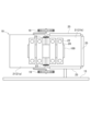
- FIG. 3 is a diagram showing the test specimen 100 and the test specimen jig 18.
- FIG. 4 is a side view of FIG. 3.
- FIG. 5 is a bottom view of FIG. 3.
- the rectangular test specimen 100 is inserted between the upper fixture 20 and the lower fixture 21.
- the lower fixture 21 is composed of a pair of lower fixtures 21a, 21b, which are formed, for example, by cutting a single stainless steel plate into two pieces and placing them at a distance from each other.
- the test specimen 100 is positioned so that its bend is located in the gap, and is fixed by fasteners 22 pressing the upper fixture 20 and the lower fixture 21 from the front and back.
- a spring 23 is attached to the front and back of the lower fixture 21 so as to cross the gap.
- the spring 23 has the function of constantly maintaining the angle between the pair of lower fixtures 21a, 21b, i.e. the bending angle of the test specimen 100, at 0°.
- Two gears 19 are attached to the lower fixture 21a of the pair of lower fixtures 21a, 21b, by shaft members 24 attached to the upper and lower sides.
- the attachment positions of the gears 19 can be adjusted as desired by adjusting the length of the shaft members 24, etc.
- FIG. 6 shows the test specimen 100 and test specimen jig 18 attached to the sample holder 25 fixed to the upper surface of the lower rotating disk 15.
- the lower fixture 21b to which the gear 19 is not attached, is accommodated in the sample holder 25.
- the lower fixture 21b is in a fixed state
- the lower fixture 21a is in a state in which it can be bent relative to the lower fixture 21b.
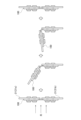
- Figure 7 shows the bending state of the test specimen 100 as it revolves around the light source 31.
- the test specimen jig 18 reaches a predetermined position (this may be multiple positions rather than one)
- the gear 19 on the test specimen side meshes with the pin rack 17 on the device side, and the force that rotates the gear 19 is used to gradually bend the test specimen 100.
- the test specimen 100 which has been bent by the force of the spring 23, returns to its original angle.
- the bending angle of the test specimen 100 can be adjusted by the size, diameter, length, shape, number of teeth, etc. of the gear 19 on the device side and the pin rack 17 on the test specimen side. For example, it can be bent to 30°, 60°, 90°, 120°, or 180°.
- the revolution speed of the test specimen 100 (the time it takes for the test specimen 100 to make one revolution around the light source 31) can be set arbitrarily. For example, if it is set to make one revolution in 15 minutes, the gear 19 on the device side and the pin rack 17 on the test specimen side will mesh and bend the test specimen 100 every 15 minutes.
- the pin rack 17 can be attached not only to one location, but also to multiple locations on the edge of the fixed disk 16. This allows the number of times the test specimen 100 is bent each time it makes one revolution around the light source 31 to be set as desired.
- Control device 8 is a diagram showing the configuration of the control device 2.
- the control device 2 includes a control unit 91, a processing unit 92, a display unit 93, and a storage unit 94.
- the control unit 91 has the function of controlling the on/off and illuminance of the light source 31.
- the control unit 91 has the function of controlling the temperature regulator 32 to keep the temperature in the accelerated deterioration test chamber 1 at a predetermined temperature.
- the control unit 91 has the function of controlling the humidity regulator 33 to keep the humidity in the accelerated deterioration test chamber 1 at a predetermined humidity.
- the control unit 91 has the function of rotating the support 13 and the upper rotating disk 14 and the lower rotating disk 15 by controlling the rotation mechanism 51.
- the processing unit 92 has the function of capturing an image of the test specimen 100 by controlling the imaging unit 71.
- the processing unit 92 has a function of measuring the deterioration progression state of the test specimen 100 (such as the thickness of the test specimen 100 and the depth of cracks) based on image information of the test specimen 100.
- the processing unit 92 has a function of controlling the progression process of the accelerated deterioration test of the test specimen 100 based on the measurement results of the deterioration progression state of the test specimen 100.
- the processing unit 92 has a function of acquiring infrared spectroscopic analysis information of the test piece 100 from the infrared spectroscopic analysis device 3.
- the processing unit 92 has a function of measuring the deterioration progression state of the test piece 100 based on the infrared spectroscopic information of the test piece 100.
- the processing unit 92 has a function of controlling the progression process of the deterioration promotion of the test piece 100 based on the measurement results of the deterioration progression state of the test piece 100.
- the display unit 93 has the function of displaying the captured image of the test specimen 100, infrared spectroscopic analysis information of the test specimen 100, and various measurement values such as the thickness of the test specimen 100 and the depth of cracks.
- the memory unit 94 has the function of storing captured images of the test specimen 100, as well as various measurement values such as the thickness of the test specimen 100 and the depth of cracks.
- control device 2 controls the light source 31, the temperature regulator 32, and the humidity regulator 33 to carry out a weather resistance test on the polymer material specimen 100 for A hours under pre-set conditions.
- the weather resistance test is set in accordance with "JIS K 5600-7-7" and "JIS K 7350-2" with a black panel temperature of 63°C, a temperature inside the tank of 38°C, and a humidity of 50% RH.
- the water spray time is 18 minutes within a 2-hour period.
- the ultraviolet radiation intensity at wavelengths of 300 nm to 400 nm is 60 W/ m2 . Under these conditions, accelerated deterioration of the test specimen 100 is performed for 100 hours.
- each test specimen 100 is bent a maximum of B degrees each time the gear 19 on the device side and the pin rack 17 on the test specimen side mesh with each other.
- Each test specimen 100 is bent, for example, to 30°, 60°, 90°, 120°, and 180°.
- the bending angle of the test specimen 100 is controlled by the size, diameter, length, shape, number of teeth, etc. of the gear 19 and pin rack 17 that are preset.
- the pin rack 17 may be provided in multiple locations instead of in one place.
- the rotation speed of the test specimen 100 is also set under preset conditions. By increasing the rotation speed, the number of bends in a given time period increases, and conversely, by decreasing the rotation speed, the number of bends in a given time period decreases.
- an imaging unit 71 is installed at an appropriate position inside the hollow of the accelerated deterioration test tank 1. That is, the imaging unit 71 is installed around each of the disks 14, 15, and 16.
- the imaging unit 71 is, for example, an optical camera, a CCD camera, or a microscope.
- the imaging unit 71 is installed at a position where it can capture an image of the vicinity of the center of the test piece 100. That is, the imaging unit 71 captures an image of the test piece 100.
- the control device 2 analyzes the captured images of the test specimens 100 and measures the thickness of each test specimen 100 and the depth of cracks occurring in each test specimen 100. The control device 2 then determines whether the crack depth of each test specimen 100 has progressed beyond a threshold, and controls whether or not to apply environmental degradation factors by the light source 31, temperature regulator 32, and humidity regulator 33, and whether or not to apply bending stress, etc. by the rotation mechanism 51, depending on the respective determination results.
- control device 2 stops the deterioration acceleration device when it is determined that the crack depth of the test specimen 100 is equal to or greater than a preset value, or when the total time of the weather resistance test is equal to or greater than a preset time, and otherwise continues the deterioration acceleration test.
- Step S101 First, the control unit 91 of the control device 2 controls the light source 31, the temperature regulator 32, the humidity regulator 33, and the rotation mechanism 51 to carry out a weather resistance test for time A under preset conditions. At this time, each time the gear 19 on the device side and the pin rack 17 on the test piece side mesh with each other, each test piece 100 is bent at a maximum of B degrees. For example, each test piece 100 is bent at 30°, 60°, 90°, 120°, and 180°.
- Step S102 Next, the imaging unit 71 captures an image of the bent portion of the test piece 100 .
- Step S103 Next, the processing unit 92 of the control device 2 analyzes the captured images of the test pieces 100 and measures the thickness of each test piece 100 and the depth of any cracks occurring in the test pieces 100 .
- Step S104 Next, the processing unit 92 of the control device 2 judges whether or not there is a test specimen whose crack depth has reached D% (e.g., 30%) of the total thickness based on the thickness and crack depth of each test specimen 100. If such a test specimen is present, this process ends, and if such a test specimen is not present, the process proceeds to step S105.
- D% e.g. 30%
- Step S105 Next, the processing unit 92 of the control device 2 judges whether the total time of the weather resistance test has reached a predetermined time, that is, whether the total time of light irradiation has reached the time limit E. If the total time of the weather resistance test has reached E hours, this process is terminated, and if E hours has not been reached, the process returns to step S101.
- measuring units 72 are disposed within the hollow interior of the accelerated deterioration test tank 1. That is, the measuring units 72 are disposed around the respective disks 14, 15, and 16. The measuring units 72 are attached to the infrared spectroscopic analyzer 3 via optical fibers. The measuring units 72 are pressed against the test specimen 100 under the control of the infrared spectroscopic analyzer 3, and function as a portion for acquiring light irradiated onto the test specimen 100.
- the infrared spectroscopic analyzer is a device that performs infrared spectroscopic analysis of the test specimen 100.
- the infrared spectroscopic analyzer 3 is a Fourier transform infrared spectrophotometer conforming to "JIS K 0117".
- the infrared spectroscopic analyzer 3 may be any analytical device that is capable of performing infrared spectroscopic analysis of the test specimen 100.
- the infrared spectroscopic analyzer 3 presses the measuring unit 72 against the test piece 100, measures the absorbance of the carbonyl and methylene groups absorbed by the test piece 100 via optical fiber, and outputs the measured values of each absorbance to the control device 2.
- the carbonyl group and the methylene group are examples of observed data. Any data that can measure the deterioration progress state of the test specimen 100 will suffice.
- the carbonyl index value of the test specimen 100 has increased to or above the threshold value, and depending on the respective determination results, it controls whether or not environmental degradation factors are applied by the light source 31, temperature regulator 32, and humidity regulator 33, and whether or not bending stress, etc. is applied by the rotation mechanism 51.
- the deterioration acceleration device is stopped; otherwise, the deterioration acceleration test is continued.
- Step S201 The infrared spectroscopic analyzer 3 performs infrared spectroscopic analysis of the test specimen 100. Specifically, the infrared spectroscopic analyzer 3 presses the measuring part 72 against the test specimen 100 and measures the absorbance of each of the carbonyl group and methylene group absorbed by the test specimen 100. The rotating mechanism 51 of the accelerated deterioration test tank 1 moves each test specimen 100 in sequence to the measuring part 72, and the infrared spectroscopic analyzer 3 measures the absorbance of each of the remaining test specimens 100.
- Step S202 Next, the processing unit 92 of the control device 2 calculates the initial value of the carbonyl index value of each test specimen 100 using the formula (1) based on the measured absorbance of the carbonyl group and methylene group of each test specimen.
- I is the absorbance at each wave number.
- I0 is the baseline absorbance at each wave number by the baseline method. The absorption position may vary depending on the state of the test specimen 100 and the measurement conditions. Therefore, the calculation formula for the carbonyl index value is not limited to formula (1).
- Step S203 Next, the control unit 91 of the control device 2 controls the light source 31, the temperature regulator 32, and the humidity regulator 33 to carry out the weather resistance test for A hours under the preset conditions.
- the weather resistance test is set in accordance with "JIS K 5600-7-7" and "JIS K 7350-2" with a black panel temperature of 63°C, a temperature inside the tank of 38°C, and a humidity of 50% RH.
- the water spray time is 18 minutes within 2 hours.
- the ultraviolet radiation intensity at wavelengths of 300 nm to 400 nm is 60 W/ m2 . Under these conditions, accelerated deterioration of the test specimen is carried out for 100 hours.
- the rotation speed is also set under preset conditions.
- the pin rack 17 on the device side is retracted to a position where it does not mesh with the gear 19 on the test specimen side.
- the pin rack 17 may be removed from the fixed disk 16, or the pin rack 17 may be moved manually or automatically inward to a position where it cannot come into contact with the gear 19.
- Step S204 Next, the infrared spectroscopic analyzer 3 performs infrared spectroscopic analysis again on the test specimens 100. Specifically, the infrared spectroscopic analyzer 3 remeasures the absorbance of each of the carbonyl group and the methylene group of each test specimen.
- Step S205 Next, the processing unit 92 of the control device 2 recalculates the carbonyl index value of each test specimen after the weather resistance test is carried out for A hours, based on the remeasured absorbances of the carbonyl group and the methylene group.
- Step S206 Next, the processing unit 92 of the control device 2 calculates, for each test specimen 100, the percentage by which the carbonyl index value after the weather resistance test has increased relative to the carbonyl index value before the weather resistance test, and determines whether there are any test specimens whose carbonyl index value has increased by more than a C % (e.g., 0.1%) preset by the user.
- a C % e.g., 0.1%) preset by the user.
- Step S207 If there is no test specimen whose carbonyl index value has increased by C% or more, the processing unit 92 of the control device 2 judges whether or not the total time of the weather resistance test has exceeded a designated D time (e.g., 3000 hours). If the total time of the weather resistance test has not exceeded D time, the process returns to step S203. If the total time of the weather resistance test has exceeded D time, all processing is terminated.
- a designated D time e.g., 3000 hours
- Step S208 If the determination result in step S206 is that there is a test specimen whose carbonyl index value has increased by C % or more, the processing unit 92 of the control device 2 calculates the time (E time) required for the carbonyl index value to increase by C % or more.
- Step S209 Next, the user moves the pin rack 17 on the device side to a position where it meshes with the gear 19 on the test specimen side.
- the control unit 91 of the control device 2 may move the position of the pin rack 17 using a movement mechanism that can control the movement of the position of the pin rack 17.
- Step S210 Next, the control device 2 performs a weather resistance test at a rotation speed such that the test specimen 100 completes one revolution in time E. At this time, each time the gear 19 on the device side and the pin rack 17 on the test specimen side mesh with each other, each test specimen 100 is bent at a maximum of B degrees.
- the bending angle of the test specimen 100 is controlled by the size and number of teeth that are set in advance. For example, each test specimen 100 is bent at 30°, 60°, 90°, 120°, and 180°.
- Step S211 Finally, the control device 2 judges whether the number of rotations (revolutions) of the test piece 100 after step S210 has exceeded F (e.g., 20). For example, if the device has one pin rack 17, it judges whether the number of times the test piece 100 has been bent by engaging with the one pin rack 17 has exceeded 20. If the number of rotations exceeds F, the process ends, and if the number of rotations does not exceed F, the process returns to step S210.
- F e.g. 20
- the degradation promotion device for promoting the composite degradation of a polymer material includes a refractable test specimen jig 18 that holds a polymer material test specimen 100, a lower rotating disk 15 that revolves the test specimen jig 18 around the light source 31, and refraction mechanisms 16, 17, and 19 that refract the test specimen jig 18 when it reaches one or more predetermined positions. This makes it possible to easily and efficiently bend the polymer material, and makes it possible to easily evaluate the resistance of the polymer material to composite degradation due to light and bending.
- a first gear on the device side and a second gear on the polymer material side may be meshed with each other to use the force that rotates the second gear.
- the first gear may be fixed to the device side, may rotate in the opposite direction to the rotation direction of the second gear, or may rotate at a different rotation speed than the rotation speed of the second gear.
- a photoelectric sensor may detect that the test specimen has passed a certain position, and the detection may be used as a trigger to rotate a motor to bend the test specimen.
- the control device 2 of the present embodiment described above can be realized, for example, as shown in FIG. 11, by using a general-purpose computer system including a CPU 901, a memory 902, a storage 903, a communication device 904, an input device 905, and an output device 906.
- the memory 902 and the storage 903 are storage devices.
- the CPU 901 executes a predetermined program loaded onto the memory 902, thereby realizing each function of the control device 2.
- the control device 2 may be implemented in one computer.
- the control device 2 may be implemented in multiple computers.
- the control device 2 may be a virtual machine implemented in a computer.
- the program for the control device 2 can be stored in a computer-readable recording medium such as a HDD, SSD, USB (Universal Serial Bus) memory, CD (Compact Disc), or DVD (Digital Versatile Disc).
- the computer-readable recording medium is, for example, a non-transitory recording medium.
- the program for the control device 2 can also be distributed via a communication network.
Landscapes
- Life Sciences & Earth Sciences (AREA)
- Biodiversity & Conservation Biology (AREA)
- Ecology (AREA)
- Environmental & Geological Engineering (AREA)
- Environmental Sciences (AREA)
- Physics & Mathematics (AREA)
- Health & Medical Sciences (AREA)
- Chemical & Material Sciences (AREA)
- Analytical Chemistry (AREA)
- Biochemistry (AREA)
- General Health & Medical Sciences (AREA)
- General Physics & Mathematics (AREA)
- Immunology (AREA)
- Pathology (AREA)
- Testing Resistance To Weather, Investigating Materials By Mechanical Methods (AREA)
Priority Applications (2)
| Application Number | Priority Date | Filing Date | Title |
|---|---|---|---|
| JP2025529026A JPWO2025004153A1 (https=) | 2023-06-26 | 2023-06-26 | |
| PCT/JP2023/023645 WO2025004153A1 (ja) | 2023-06-26 | 2023-06-26 | 劣化促進装置 |
Applications Claiming Priority (1)
| Application Number | Priority Date | Filing Date | Title |
|---|---|---|---|
| PCT/JP2023/023645 WO2025004153A1 (ja) | 2023-06-26 | 2023-06-26 | 劣化促進装置 |
Publications (1)
| Publication Number | Publication Date |
|---|---|
| WO2025004153A1 true WO2025004153A1 (ja) | 2025-01-02 |
Family
ID=93938004
Family Applications (1)
| Application Number | Title | Priority Date | Filing Date |
|---|---|---|---|
| PCT/JP2023/023645 Ceased WO2025004153A1 (ja) | 2023-06-26 | 2023-06-26 | 劣化促進装置 |
Country Status (2)
| Country | Link |
|---|---|
| JP (1) | JPWO2025004153A1 (https=) |
| WO (1) | WO2025004153A1 (https=) |
Citations (4)
| Publication number | Priority date | Publication date | Assignee | Title |
|---|---|---|---|---|
| JPS60117128A (ja) * | 1983-11-30 | 1985-06-24 | Iwasaki Electric Co Ltd | 耐候性試験のプレ試験方法 |
| JPH0431739A (ja) * | 1990-05-28 | 1992-02-03 | Suga Shikenki Kk | 疲労耐候試験方法 |
| JP2016200497A (ja) * | 2015-04-10 | 2016-12-01 | 日新製鋼株式会社 | 塗装ステンレス鋼板の曲げ加工部の耐塗膜剥離性の評価方法 |
| JP2018072216A (ja) * | 2016-10-31 | 2018-05-10 | 積水ハウス株式会社 | シーリング材の動暴露試験装置 |
-
2023
- 2023-06-26 JP JP2025529026A patent/JPWO2025004153A1/ja active Pending
- 2023-06-26 WO PCT/JP2023/023645 patent/WO2025004153A1/ja not_active Ceased
Patent Citations (4)
| Publication number | Priority date | Publication date | Assignee | Title |
|---|---|---|---|---|
| JPS60117128A (ja) * | 1983-11-30 | 1985-06-24 | Iwasaki Electric Co Ltd | 耐候性試験のプレ試験方法 |
| JPH0431739A (ja) * | 1990-05-28 | 1992-02-03 | Suga Shikenki Kk | 疲労耐候試験方法 |
| JP2016200497A (ja) * | 2015-04-10 | 2016-12-01 | 日新製鋼株式会社 | 塗装ステンレス鋼板の曲げ加工部の耐塗膜剥離性の評価方法 |
| JP2018072216A (ja) * | 2016-10-31 | 2018-05-10 | 積水ハウス株式会社 | シーリング材の動暴露試験装置 |
Also Published As
| Publication number | Publication date |
|---|---|
| JPWO2025004153A1 (https=) | 2025-01-02 |
Similar Documents
| Publication | Publication Date | Title |
|---|---|---|
| CN104053982B (zh) | 使用无电极等离子体光源加速光降解的测试装置和方法 | |
| CN112005091A (zh) | 光学样品表征 | |
| CA2832045A1 (en) | Method and apparatus for evaluating a sample through variable angle raman spectroscopy | |
| TW202102889A (zh) | 漫射光測試站 | |
| CN115004000A (zh) | 光学样本表征 | |
| CN105067528B (zh) | 二维共焦显微非线性强度扫描系统和测量方法 | |
| CN104880433B (zh) | 基于离轴抛物反射镜的高分辨率mems微镜红外光谱仪 | |
| CN104535412A (zh) | 基于紫外照明dic的高温材料机械性能加载测量系统及测量方法 | |
| EP2450672A3 (de) | Optische Winkelmesseinrichtung | |
| CN106872415A (zh) | 结合显微成像的多波长样品光限幅性能的测量装置和测量方法 | |
| JP2015515011A (ja) | 内蔵atr及び付属品区画を有する分光計 | |
| CN103364360B (zh) | 水分测定仪 | |
| CN101482504A (zh) | 检测材料激光空间散射特性的测试装置及其检测方法 | |
| WO2025004153A1 (ja) | 劣化促進装置 | |
| WO2014005987A1 (en) | An add-on system for photochemical atr-ir spectroscopy studies | |
| CN110031416B (zh) | 气体浓度检测装置及方法 | |
| CN205940471U (zh) | 一种测量玻璃厚度和折射率的装置 | |
| ES2726992T3 (es) | Monitoreo de proceso para curado por UV | |
| WO2025203367A1 (ja) | 劣化促進装置 | |
| CN104568838A (zh) | 基于全内反射法的宽光谱范围物质色散的自动测量装置 | |
| JP2014134449A (ja) | 凹面光学素子の測定装置及び凹面回折格子の測定装置並びに平面回折格子の測定装置 | |
| EP3058342B1 (fr) | Procédé d'évaluation de l'endommagement d'un matériau composite recouvert d'une peinture, mesurant sur le spectrogramme deux critères distincts | |
| WO2024134874A1 (ja) | 劣化促進方法、及び、劣化促進装置 | |
| CN112611746A (zh) | 一种对于材料微区的吸收光谱检测装置及检测方法 | |
| JP2020197505A (ja) | 樹脂成形品の内部の残留応力を評価する方法 |
Legal Events
| Date | Code | Title | Description |
|---|---|---|---|
| 121 | Ep: the epo has been informed by wipo that ep was designated in this application |
Ref document number: 23943555 Country of ref document: EP Kind code of ref document: A1 |
|
| ENP | Entry into the national phase |
Ref document number: 2025529026 Country of ref document: JP Kind code of ref document: A |
|
| WWE | Wipo information: entry into national phase |
Ref document number: 2025529026 Country of ref document: JP |
|
| NENP | Non-entry into the national phase |
Ref country code: DE |