WO2024262532A1 - 柱梁接合構造 - Google Patents
柱梁接合構造 Download PDFInfo
- Publication number
- WO2024262532A1 WO2024262532A1 PCT/JP2024/022210 JP2024022210W WO2024262532A1 WO 2024262532 A1 WO2024262532 A1 WO 2024262532A1 JP 2024022210 W JP2024022210 W JP 2024022210W WO 2024262532 A1 WO2024262532 A1 WO 2024262532A1
- Authority
- WO
- WIPO (PCT)
- Prior art keywords
- column
- joined
- joint structure
- flange
- joint
- Prior art date
- Legal status (The legal status is an assumption and is not a legal conclusion. Google has not performed a legal analysis and makes no representation as to the accuracy of the status listed.)
- Ceased
Links
Images







Classifications
-
- B—PERFORMING OPERATIONS; TRANSPORTING
- B23—MACHINE TOOLS; METAL-WORKING NOT OTHERWISE PROVIDED FOR
- B23K—SOLDERING OR UNSOLDERING; WELDING; CLADDING OR PLATING BY SOLDERING OR WELDING; CUTTING BY APPLYING HEAT LOCALLY, e.g. FLAME CUTTING; WORKING BY LASER BEAM
- B23K9/00—Arc welding or cutting
-
- E—FIXED CONSTRUCTIONS
- E04—BUILDING
- E04B—GENERAL BUILDING CONSTRUCTIONS; WALLS, e.g. PARTITIONS; ROOFS; FLOORS; CEILINGS; INSULATION OR OTHER PROTECTION OF BUILDINGS
- E04B1/00—Constructions in general; Structures which are not restricted either to walls, e.g. partitions, or floors or ceilings or roofs
- E04B1/18—Structures comprising elongated load-supporting parts, e.g. columns, girders, skeletons
- E04B1/24—Structures comprising elongated load-supporting parts, e.g. columns, girders, skeletons the supporting parts consisting of metal
-
- E—FIXED CONSTRUCTIONS
- E04—BUILDING
- E04B—GENERAL BUILDING CONSTRUCTIONS; WALLS, e.g. PARTITIONS; ROOFS; FLOORS; CEILINGS; INSULATION OR OTHER PROTECTION OF BUILDINGS
- E04B1/00—Constructions in general; Structures which are not restricted either to walls, e.g. partitions, or floors or ceilings or roofs
- E04B1/38—Connections for building structures in general
- E04B1/58—Connections for building structures in general of bar-shaped building elements
Definitions
- the present invention relates to a beam-column joint structure.
- This application claims priority based on Japanese Patent Application No. 2023-099747, filed on June 19, 2023, the contents of which are incorporated herein by reference.
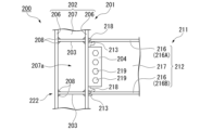
- the column-beam joint structure 200 includes a column 201 and a beam 211.
- the column 201 includes a column body 202 made of a column H-shaped steel (H-shaped steel), a pair of stiffeners (diaphragms, first reinforcing plates, continuous plates) 203, and a shear plate 204.
- the column body 202 has a pair of column flanges 206 and a column web 207, and extends in the vertical direction.
- Each stiffener 203 is a horizontal stiffener and is disposed along a horizontal plane.
- each stiffener 203 is disposed at the same position as a pair of beam flanges 216 (described later) of the beam 211.
- Each stiffener 203 is joined to a pair of column flanges 206 and a column web 207 of the column 201 (column body 202) by welded parts 208 formed by welding.
- the shear plate 204 is joined to the column flange 206 of the column 201 by welding or the like.
- the beam 211 has a beam H-shaped steel (H-shaped steel) 212 and a pair of backing metals 213.
- the beam H-shaped steel 212 is, for example, an H-shaped steel specified by JIS (Japanese Industrial Standards) G 3192:2014 Shape, dimensions, mass and tolerances thereof of hot-rolled steel (hereinafter simply referred to as JIS G 3192).
- the beam H-shaped steel 212 has a pair of beam flanges 216 and a beam web 217.
- the pair of beam flanges 216 are arranged to face each other in the vertical direction.
- the beam flange 216 arranged at the top is an upper flange 216A
- the beam flange 216 arranged at the bottom is a lower flange 216B.
- Each beam flange 216 is joined to the column flange 206 of the column body 202 by a weld 218 with the backing metal 213 attached below the beam flange 216.
- the beam web 217 and the shear plate 204 are connected to each other by a fastening member 219 such as a high-strength bolt.
- the beam web 217 may be connected to the shear plate 204 by welding in addition to being connected to the shear plate 204 by the fastening member 219.
- the beam web 217 may also be joined to the column flange 206 directly by welding.
- the column 201 and the beam 211 are connected to each other at a joint 222.
- the joint 222 is a so-called pre-northridge joint.
- the portion of the column web 207 that is within the range of the beam 211 in the vertical direction is defined as the joint panel 207a.
- Types A to D which correspond to the cracks represented by lines LA, LB, LC, and LD, as shown in FIG.
- Types A and B depend on the fracture toughness in the direction of tearing the column flange 206 parallel to the main surface of the column flange 206 (S direction (plate thickness direction S) in FIG. 1 described later).
- S direction plate thickness direction S
- Type C the line LC representing the crack advances to penetrate the beam flange 216.
- Type D depends on the fracture toughness in the direction (L direction) dividing the column flange 206 in the material axis direction (longitudinal direction).
- Type D is further induced by local bending deformation of the column flange 206 caused by shear deformation of the joint panel 207a.
- a pair of beams 211 are joined to the column 201.
- Local kink deformation occurs in a range R1 of the column flange 206 of the column 201 and in a range R2 of the beam flange 216 of the beam 211.
- These ranges R1 and R2 are the parts where local bending deformation occurs.
- all of the cases except for Type C show that a crack initiated and propagated in the slit formed between the backing metal 213 of the lower flange 216B and the column 201.
- the beam-column joint structures currently used in earthquake-resistant structures in Europe and the United States have detailed structures of the joints that are designed to withstand repeated deformations, based on the type of failure at joint 222 of beam-column joint structure 200 that occurred in the Northridge earthquake.
- the column-beam joint structure 200B is required to take the following measures (1) to (3).
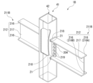
- the pillar 201 is reinforced by a stiffener 203.
- the joint panel 207a of the column 201 is reinforced by a doubler plate (second reinforcing plate) 225 to thicken the column web 207.
- beam 211A After the end of the beam 211A is welded on-site, the backing metal 213 attached to the lower flange 216B of the beam 211A is removed and reinforcement welding is performed. That is, beam 211A does not have a backing metal 213 around the lower flange 216B in each configuration of beam 211.
- a doubler plate 225 is provided on the column 201 and is joined to the joint panel 207a.
- the joint 222A between the column 201 and the beam 211A is a so-called Post-Northridge joint.
- the joint 222A is a joint for preventing destruction of Types A to D.
- the measures (1) and (2) suppress the plastic deformation of the column flange 206 and the joint panel 207a.
- the arc gouging method is used to remove the backing metal 213 in the measure (3).
- Reinforcing welding is performed from below the removed portion upward in the portion where the backing metal 213 has been removed. The reinforcing welding eliminates slits that are the starting point of fracture.
- the present invention was made in consideration of these problems, and aims to provide a column-beam joint structure that ensures the structural stability of buildings that use column-beam joint structures and has joints with high energy absorption performance.
- Aspect 1 of the present invention comprises a column having a column main body made of a column H-shaped steel, a square steel pipe, or a welded assembled box section, and a beam having a beam H-shaped steel, in which a pair of beam flanges of the beam H-shaped steel are directly joined to a joined plate of the column main body via a weld, and the joined plates are the column flanges of the column H-shaped steel, or the square steel pipe and the flat plate portion of the welded assembled box section, and when a position where a central axis of the column main body and a central axis of the beam H-shaped steel intersect is defined as an intersection position,
- This is a column-beam joint structure in which, at the intersection position, a ratio of the total plastic strength of the column to the total plastic strength of the beam is 1.5 or more and 3.0 or less, and, at the intersection position, a ratio of the total plastic strength of the beam to the total
- the inventors have found, as a result of intensive research, that in order to improve the energy absorption performance at the joint between the column and the beam in a column-beam joint structure, it is necessary to absorb the energy acting on the column-beam joint structure not only by the beam but also by the joint panel.
- the joint panel which is expected to have a stable increase in strength after plasticization as long as the column flange does not break, yields first, and the beam yields following the increase in strength of the joint panel due to yield.
- the beam-panel strength ratio which is the ratio of the total plastic strength of the beam to the total plastic strength of the joint panel, should be 1.05 or more in order for the joint panel to yield first.
- the joint panel is expected to increase in strength to about 1.5 times the total plastic strength due to strain hardening caused by repeated plastic deformation.
- the beam-panel strength ratio to 1.5 or less, not only the joint panel but also the beam can be plasticized in the process of increasing strength after the joint panel has yielded first, and both the beam and the joint panel can absorb the energy acting on the column-beam joint structure. Therefore, the energy absorption performance of the joint between the column and the beam can be improved.
- the column-beam strength ratio which is the ratio of the total plastic strength of the columns to the total plastic strength of the beams, is preferably 1.5 or more. To prevent the columns from performing excessively well and becoming economically unreasonable, it is preferable to keep the column-beam strength ratio at around 2.5 to 3.0 or less.
- Aspect 2 of the present invention may be a column-beam joining structure as described in (1), which includes a backing metal joined to the lower flange of the pair of beam flanges located lower and to the joined plate via the weld, the backing metal is attached below the lower flange, and the upper surface of the backing metal is formed with a slope that gradually slopes downward as it approaches the joined plate, and the weld is also formed within the slope.
- Aspect 5 of the present invention may be a column-beam joint structure described in any one of (1) to (4), which does not have a first reinforcing plate arranged at the same position in the vertical direction as the pair of beam flanges and joined to the column body.
- this invention since the pillar does not have a first reinforcing plate joined to the pillar body, construction of the pillar can be carried out relatively easily.
- Aspect 6 of the present invention may be a column-beam joint structure described in any one of (1) to (5), which does not have a second reinforcing plate joined to the column web or the flat plate portion so as to thicken the column web or the flat plate portion.
- this invention since the pillar does not have a second reinforcing plate joined to the pillar web or flat plate portion, construction of the pillar can be carried out relatively easily.
- the column-beam joint structure of the present invention ensures the structural stability of buildings in which it is used, and provides a column-beam joint structure with joints that have high energy absorption performance.
- FIG. 1 is a front view illustrating a building in which a column-beam joint structure is used.
- FIG. 2 is a front view for explaining an outline of a test device for a column-beam joint structure.
- FIG. 2 is a diagram illustrating a loading history 1 applied to a sample 1.
- FIG. 2 is a diagram illustrating a loading history 2 applied to a sample 2.
- FIG. 1 This is a front view of the main parts of a beam-column joint structure that was used before the Northridge earthquake. 1 is an enlarged view of a key part explaining the failure mode of the same beam-column joint structure.
- FIG. This is a side view showing the state in which a joint panel of a column-beam joint structure is undergoing shear deformation. This is an oblique view of the main parts of a beam-column joint structure that has traditionally been used since the Northridge earthquake.
- a column-beam joint structure 1 of the present embodiment is used in a building 2.
- the column-beam joint structure 1 includes a column 11 and a pair of beams 211B.
- the number of beams 211B included in the column-beam joint structure 1 is not limited, and may be one, or may be three or more.
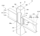
- the column 11 has a column body 12 made of a column H-shaped steel (H-shaped steel).
- the column body 12 extends along the vertical direction (or the first direction).
- the column body 12 has a pair of column flanges (joined plates) 16 and a column web 17.
- the pair of column flanges 16 and the web 17 are preferably formed of rolled steel material.
- the column 11 does not have a stiffener 203 and a doubler plate 225 as shown in FIG. 23 etc. Note that the column 11 may have at least one of the stiffener 203 and the doubler plate 225.
- the beam 211B has a pair of backing metals 21 instead of the pair of backing metals 213 in each configuration of the beam 211 (which extends in a second direction, which is horizontal in this example).
- the end of each beam flange 216 on the column flange 16 side is formed with a slope 216 a that gradually slopes downward as it approaches the column flange 16 .
- the first direction and the second direction are substantially perpendicular to each other.
- the backing metal 21 has a rectangular parallelepiped shape. Each backing metal 21 is attached below each beam flange 216 (lower flange 216B). More specifically, each backing metal 21 is attached from below each beam flange 216 to each beam flange 216 and column flange 16 by fillet welding, tack welding, or the like. Note that the backing metal 21 does not need to be used for the upper flange 216A, and the backing metal 213 may be used instead. At the end of the upper surface of the backing metal 21 on the side of the column flange 16, a slope 21a is formed that gradually slopes downward as it approaches the column flange 16. That is, the backing metal 21 is chamfered.
- the slope 21a is continuous with the slope 216a of the beam flange 216.
- the welded portion 218 is disposed within the slope 216a of the beam flange 216 (on the slope 216a) and within the slope 21a of the backing metal 21 (on the slope 21a).
- the backing metal 21 is joined to the beam flange 216 (lower flange 216B) and the column flange 16 via the welded portion 218. In this manner, each beam flange 216 is directly joined to each of the column flanges 16 of the column body 12 via welds 218 . It is difficult to place a weld 218 between the column flange 16 and the backing metal 21, and a slit 21b is likely to be formed.
- the portion of the column web 17 within the range of the beam 211B in the vertical direction is defined as the joint panel 17a.
- the position where the central axis O1 of the column body 12 intersects with the central axis O2 of the beam 211B (H-shaped beam steel) is defined as the intersection position P1.
- the column 11 and the pair of beams 211B are connected to each other at joints 23.
- the intersecting position P1 is a node of the joints 23.
- the column body 12 is described as being made of an H-shaped column steel, the column body may be made of a square steel pipe or a welded assembled box section (welded assembled box section column).
- JIS Z 2242 2018 Charpy impact test method for metallic materials (hereinafter, simply referred to as JIS Z 2242) is known.
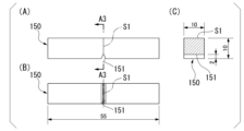
- JIS Z 2242 a test is performed using a Charpy test piece 150 shown in FIG. 3.
- the axial length of the Charpy test piece 150 is 55 mm.
- the cross-sectional shape of the Charpy test piece 150 perpendicular to the axial direction is a rectangle of 10 mm x 10 mm.
- a notch 151 is formed on the outer surface at the center in the axial direction.
- the notch 151 is formed on a plane S1 perpendicular to the axial direction.
- the notch 151 is a V-notch with a depth of 2 mm.
- the notch 151 is partially formed in the Charpy test piece 150 in this depth direction.
- the notch 151 extends in a direction perpendicular to the axial direction and is formed across the entire width of the Charpy test piece 150 .
- Fig. 4 shows the Charpy test piece 150 in a schematic manner, including the shape of the notch 151 described later.
- the rolled steel material 155 is manufactured by a rolling mill, in which steel is thinned in a thickness direction S while being stretched in a rolled direction L.
- the direction perpendicular to the thickness direction S and the rolled direction L is called a width direction T.
- the roll direction L and the width direction T are each a thickness-orthogonal direction (a direction perpendicular to the thickness direction S).
- a Charpy test piece 150 in which a plane S1 on which the notch 151 is formed is perpendicular to the thickness direction S and the depth direction of the notch 151 is parallel to the width direction T is expressed as "S-T" or "Charpy test piece 150 ST .”
- Charpy test pieces 150LS , 150LT , 150TS , and 150TL are used in which the plane S1 on which the notch 151 is formed is perpendicular to the roll direction L or the width direction T.
- the Charpy impact test using the Charpy test pieces 150ST and 150SL perpendicular to the plate thickness direction S is performed according to the procedure of JIS Z 2242, except for the procedure for taking the Charpy test pieces 150 used.
- the plate thickness of the column flange 16 is defined as t1 (mm).
- the surface of the column flange 16 facing the plate thickness direction S, to which the extending bar 156 described later is joined, is called the surface 16a.
- the distance in the plate thickness direction S between the notch 151 of the Charpy test specimen 150SL and the surface 16a is defined as t2 (mm).
- a cylindrical extension rod 156 is joined by friction welding to the surface 16a of the column flange 16.
- the reason for joining by friction welding is to keep the heat-affected zone (HAZ) formed at the joining portion between the column flange 16 and the extension rod 156 as small as possible.
- HZ heat-affected zone
- the extension rod 156 is arranged so that its axial direction is along the plate thickness direction S.
- the extension rod 156 has a length of 120 mm and a diameter of 30 mm.
- the material forming the extension rod 156 is preferably the same as the material forming the column flange 16. The friction welding is performed so that the entire cross section of the extension rod 156 is joined to the surface 16a of the column flange 16.
- the distance t2 is set to (t1/4).
- the distance t2 is set to 10 mm. Since a heat-affected zone is formed at the joint between the column flange 16 and the extension rod 156, although the heat-affected zone is narrow, it is preferable to set the distance t2 as described above according to the plate thickness t1.
- the plate thickness t1 of the column flange 16 is 19 mm or more.
- Fig. 6 shows the test results according to JIS Z 2242 using the Charpy test piece 150LT , in which the plane S1 on which the notch 151 is formed is perpendicular to the roll direction L.
- the horizontal axis represents the temperature (°C) of the Charpy test piece 150LT
- the vertical axis represents the Charpy absorbed energy (J).
- the Charpy absorbed energy of the Charpy test pieces 150LS , 150LT, 150TS , and 150TL in which the plane S1 on which the notch 151 is formed is perpendicular to the roll direction L
- the Charpy absorbed energy vE(L, T ) in the roll direction L is referred to as the Charpy absorbed energy vE(L, T ) in the roll direction L.
- the direction perpendicular to the plate thickness is the roll direction L
- the direction perpendicular to the plate thickness may be the width direction T.
- the open circles represent the results for the high toughness steel material used in the column flange 16.
- the solid line L1 represents a curve that approximates the results represented by the open circles.
- the open triangles represent the results for a general steel material (hereinafter referred to as a conventional steel material) that has been conventionally used in the column flange 16 for comparison.
- the dotted line L2 represents a curve that approximates the results represented by the open triangles.
- Line L3 represents the required performance based on Eurocodes and AISC (American Institute of Steel Construction). The required performance is that the Charpy absorbed energy is 27 J or more at temperatures from -21°C to -20°C.
- the Charpy absorbed energy increased as the temperature increased. Regardless of the temperature, the Charpy absorbed energy of the high-toughness steel was greater than or equal to that of the conventional steel. At temperatures between -60°C and 80°C, the Charpy absorbed energy of both the high toughness steel and the conventional steel met the required performance based on the Eurocodes and AISC.
Landscapes
- Engineering & Computer Science (AREA)
- Architecture (AREA)
- Physics & Mathematics (AREA)
- Electromagnetism (AREA)
- Civil Engineering (AREA)
- Structural Engineering (AREA)
- Plasma & Fusion (AREA)
- Mechanical Engineering (AREA)
- Joining Of Building Structures In Genera (AREA)
Priority Applications (1)
| Application Number | Priority Date | Filing Date | Title |
|---|---|---|---|
| JP2025508690A JP7737072B2 (ja) | 2023-06-19 | 2024-06-19 | 柱梁接合構造 |
Applications Claiming Priority (2)
| Application Number | Priority Date | Filing Date | Title |
|---|---|---|---|
| JP2023099747 | 2023-06-19 | ||
| JP2023-099747 | 2023-06-19 |
Publications (1)
| Publication Number | Publication Date |
|---|---|
| WO2024262532A1 true WO2024262532A1 (ja) | 2024-12-26 |
Family
ID=93935508
Family Applications (1)
| Application Number | Title | Priority Date | Filing Date |
|---|---|---|---|
| PCT/JP2024/022210 Ceased WO2024262532A1 (ja) | 2023-06-19 | 2024-06-19 | 柱梁接合構造 |
Country Status (2)
| Country | Link |
|---|---|
| JP (1) | JP7737072B2 (https=) |
| WO (1) | WO2024262532A1 (https=) |
Citations (7)
| Publication number | Priority date | Publication date | Assignee | Title |
|---|---|---|---|---|
| JPH09271992A (ja) * | 1996-04-09 | 1997-10-21 | Kobe Steel Ltd | T継手用裏当て材 |
| US20090294426A1 (en) * | 2008-06-03 | 2009-12-03 | Bong William L | System and method for beam-to-column welding |
| JP2016160594A (ja) * | 2015-02-27 | 2016-09-05 | 新日鐵住金株式会社 | 柱梁接合部パネルゾーンの補強構造 |
| JP2016180163A (ja) * | 2015-03-25 | 2016-10-13 | Jfeスチール株式会社 | 溶接熱影響部靭性に優れた低降伏比高張力鋼板 |
| JP2017155511A (ja) * | 2016-03-03 | 2017-09-07 | 新日鐵住金株式会社 | 柱梁仕口部及び柱梁接合方法 |
| JP2018184742A (ja) * | 2017-04-25 | 2018-11-22 | Jfeスチール株式会社 | ノンダイアフラム型の柱梁接合構造体 |
| JP2024092476A (ja) * | 2022-12-26 | 2024-07-08 | Jfeスチール株式会社 | 柱梁接合部およびその設計方法 |
-
2024
- 2024-06-19 WO PCT/JP2024/022210 patent/WO2024262532A1/ja not_active Ceased
- 2024-06-19 JP JP2025508690A patent/JP7737072B2/ja active Active
Patent Citations (7)
| Publication number | Priority date | Publication date | Assignee | Title |
|---|---|---|---|---|
| JPH09271992A (ja) * | 1996-04-09 | 1997-10-21 | Kobe Steel Ltd | T継手用裏当て材 |
| US20090294426A1 (en) * | 2008-06-03 | 2009-12-03 | Bong William L | System and method for beam-to-column welding |
| JP2016160594A (ja) * | 2015-02-27 | 2016-09-05 | 新日鐵住金株式会社 | 柱梁接合部パネルゾーンの補強構造 |
| JP2016180163A (ja) * | 2015-03-25 | 2016-10-13 | Jfeスチール株式会社 | 溶接熱影響部靭性に優れた低降伏比高張力鋼板 |
| JP2017155511A (ja) * | 2016-03-03 | 2017-09-07 | 新日鐵住金株式会社 | 柱梁仕口部及び柱梁接合方法 |
| JP2018184742A (ja) * | 2017-04-25 | 2018-11-22 | Jfeスチール株式会社 | ノンダイアフラム型の柱梁接合構造体 |
| JP2024092476A (ja) * | 2022-12-26 | 2024-07-08 | Jfeスチール株式会社 | 柱梁接合部およびその設計方法 |
Also Published As
| Publication number | Publication date |
|---|---|
| JPWO2024262532A1 (https=) | 2024-12-26 |
| JP7737072B2 (ja) | 2025-09-10 |
Similar Documents
| Publication | Publication Date | Title |
|---|---|---|
| Sadek et al. | An experimental and computational study of steel moment connections under a column removal scenario | |
| Ricles et al. | Development of improved welded moment connections for earthquake-resistant design | |
| Mao et al. | Effect of local details on ductility of welded moment connections | |
| Shi et al. | Experimental study of cyclic behavior of retrofitted beam-to-column joints with welded haunches | |
| Chen et al. | Experimental investigation on earthquake-resilient steel beam-to-column joints with replaceable buckling-restrained fuses | |
| JP2011001792A (ja) | ラーメン骨組の柱梁接合部構造および圧延h形鋼 | |
| Roudsari et al. | The effect of stiffener on behavior of reduced beam section connections in steel moment-resisting frames | |
| Lho et al. | Flexural capacity of plate girders with very slender corrugated webs | |
| Oh et al. | Seismic performance evaluation of Korean column-tree steel moment connections | |
| Najafgholipour et al. | An alternative detail for continuity plates in steel beam to box-column moment-connections | |
| TWI271465B (en) | Section steel and wall body using the section steel | |
| JP7143781B2 (ja) | 梁端接合部 | |
| Main et al. | An experimental and computational study of precast concrete moment frames under a column removal scenario | |
| JP7737072B2 (ja) | 柱梁接合構造 | |
| EP4481142A1 (en) | Beam-column joint structure | |
| Oh et al. | Experimental verification of seismic performance of built-up beam-to-column connections with ductile detail | |
| JP7718404B2 (ja) | 柱梁接合部およびその設計方法 | |
| Barsom et al. | Failure analysis of welded steel moment-resisting frame connections | |
| Eslami et al. | Rotation capacity of composite beam connected to RHS column, experimental test results | |
| Eslami et al. | Elasto-plastic behavior of composite beam connected to RHS column, experimental test results | |
| Oba et al. | Cyclic loading test of cruciform frame using high strength steel box-section column to beam moment connection with exterior diaphragm | |
| Hoffman et al. | Analysis of stress distribution and failure behavior of cellular beams | |
| US20190145102A1 (en) | C-sections and composite decks formed by cold-formed sheets for a system of composite reinforced concrete columns | |
| Chen et al. | Shear behaviour of panel zone in steel beam-to-T-shaped section column joints | |
| WO2024262537A1 (ja) | 鋼材及び鋼材の用途 |
Legal Events
| Date | Code | Title | Description |
|---|---|---|---|
| 121 | Ep: the epo has been informed by wipo that ep was designated in this application |
Ref document number: 24825933 Country of ref document: EP Kind code of ref document: A1 |
|
| WWE | Wipo information: entry into national phase |
Ref document number: 2025508690 Country of ref document: JP |
|
| NENP | Non-entry into the national phase |
Ref country code: DE |