WO2024262256A1 - 静電チャック部材および静電チャック装置 - Google Patents
静電チャック部材および静電チャック装置 Download PDFInfo
- Publication number
- WO2024262256A1 WO2024262256A1 PCT/JP2024/019480 JP2024019480W WO2024262256A1 WO 2024262256 A1 WO2024262256 A1 WO 2024262256A1 JP 2024019480 W JP2024019480 W JP 2024019480W WO 2024262256 A1 WO2024262256 A1 WO 2024262256A1
- Authority
- WO
- WIPO (PCT)
- Prior art keywords
- electrostatic chuck
- cylindrical member
- dielectric substrate
- shield layer
- mounting surface
- Prior art date
- Legal status (The legal status is an assumption and is not a legal conclusion. Google has not performed a legal analysis and makes no representation as to the accuracy of the status listed.)
- Ceased
Links
Images



Classifications
-
- H—ELECTRICITY
- H10—SEMICONDUCTOR DEVICES; ELECTRIC SOLID-STATE DEVICES NOT OTHERWISE PROVIDED FOR
- H10P—GENERIC PROCESSES OR APPARATUS FOR THE MANUFACTURE OR TREATMENT OF DEVICES COVERED BY CLASS H10
- H10P72/00—Handling or holding of wafers, substrates or devices during manufacture or treatment thereof
- H10P72/70—Handling or holding of wafers, substrates or devices during manufacture or treatment thereof for supporting or gripping
- H10P72/72—Handling or holding of wafers, substrates or devices during manufacture or treatment thereof for supporting or gripping using electrostatic chucks
- H10P72/722—Details of electrostatic chucks
-
- H—ELECTRICITY
- H01—ELECTRIC ELEMENTS
- H01J—ELECTRIC DISCHARGE TUBES OR DISCHARGE LAMPS
- H01J37/00—Discharge tubes with provision for introducing objects or material to be exposed to the discharge, e.g. for the purpose of examination or processing thereof
- H01J37/32—Gas-filled discharge tubes
- H01J37/32431—Constructional details of the reactor
- H01J37/32532—Electrodes
- H01J37/32568—Relative arrangement or disposition of electrodes; moving means
-
- H—ELECTRICITY
- H01—ELECTRIC ELEMENTS
- H01J—ELECTRIC DISCHARGE TUBES OR DISCHARGE LAMPS
- H01J37/00—Discharge tubes with provision for introducing objects or material to be exposed to the discharge, e.g. for the purpose of examination or processing thereof
- H01J37/32—Gas-filled discharge tubes
- H01J37/32431—Constructional details of the reactor
- H01J37/32715—Workpiece holder
-
- H—ELECTRICITY
- H02—GENERATION; CONVERSION OR DISTRIBUTION OF ELECTRIC POWER
- H02N—ELECTRIC MACHINES NOT OTHERWISE PROVIDED FOR
- H02N13/00—Clutches or holding devices using electrostatic attraction, e.g. using Johnson-Rahbek effect
-
- H—ELECTRICITY
- H10—SEMICONDUCTOR DEVICES; ELECTRIC SOLID-STATE DEVICES NOT OTHERWISE PROVIDED FOR
- H10P—GENERIC PROCESSES OR APPARATUS FOR THE MANUFACTURE OR TREATMENT OF DEVICES COVERED BY CLASS H10
- H10P50/00—Etching of wafers, substrates or parts of devices
- H10P50/20—Dry etching; Plasma etching; Reactive-ion etching
- H10P50/24—Dry etching; Plasma etching; Reactive-ion etching of semiconductor materials
- H10P50/242—Dry etching; Plasma etching; Reactive-ion etching of semiconductor materials of Group IV materials
-
- H—ELECTRICITY
- H10—SEMICONDUCTOR DEVICES; ELECTRIC SOLID-STATE DEVICES NOT OTHERWISE PROVIDED FOR
- H10P—GENERIC PROCESSES OR APPARATUS FOR THE MANUFACTURE OR TREATMENT OF DEVICES COVERED BY CLASS H10
- H10P72/00—Handling or holding of wafers, substrates or devices during manufacture or treatment thereof
- H10P72/70—Handling or holding of wafers, substrates or devices during manufacture or treatment thereof for supporting or gripping
-
- H—ELECTRICITY
- H10—SEMICONDUCTOR DEVICES; ELECTRIC SOLID-STATE DEVICES NOT OTHERWISE PROVIDED FOR
- H10P—GENERIC PROCESSES OR APPARATUS FOR THE MANUFACTURE OR TREATMENT OF DEVICES COVERED BY CLASS H10
- H10P72/00—Handling or holding of wafers, substrates or devices during manufacture or treatment thereof
- H10P72/70—Handling or holding of wafers, substrates or devices during manufacture or treatment thereof for supporting or gripping
- H10P72/76—Handling or holding of wafers, substrates or devices during manufacture or treatment thereof for supporting or gripping using mechanical means, e.g. clamps or pinches
- H10P72/7604—Handling or holding of wafers, substrates or devices during manufacture or treatment thereof for supporting or gripping using mechanical means, e.g. clamps or pinches the wafers being placed on a susceptor, stage or support
- H10P72/7624—Handling or holding of wafers, substrates or devices during manufacture or treatment thereof for supporting or gripping using mechanical means, e.g. clamps or pinches the wafers being placed on a susceptor, stage or support characterised by the mechanical construction of the susceptor, stage or support
Definitions
- the present invention relates to an electrostatic chuck member and an electrostatic chuck device.
- This application claims priority based on Japanese Patent Application No. 2023-100070, filed on June 19, 2023, the contents of which are incorporated herein by reference.
- Patent Document 1 describes such an electrostatic chuck device having a configuration in a sample stage that electrostatically attracts the workpiece, and multiple gas holes that supply heat transfer gas between the workpiece and the sample stage to control the temperature of the workpiece.
- the gas supply through-holes can be the starting point of discharges that can lead to damage to semiconductor wafers.
- plasma etching devices for semiconductor manufacturing have become increasingly powerful in order to process deep holes due to the increasing number of semiconductor layers. For this reason, there is a need to suppress the occurrence of abnormal discharges inside the gas holes.
- One of the objectives of the present invention is to provide an electrostatic chuck device that can suppress abnormal discharge inside the gas hole.
- An electrostatic chuck member comprising: a plate-shaped dielectric substrate having a mounting surface on which a plate-shaped sample is placed and a gas hole penetrating in a thickness direction, an attraction electrode disposed inside the dielectric substrate, a bias electrode disposed inside the dielectric substrate, a conductive cylindrical member surrounding the gas hole, and a conductive shielding layer disposed inside the dielectric substrate on an opposite side to the mounting surface side with respect to the attraction electrode and the bias electrode, the conductive shielding layer extending from an outer circumferential surface of the cylindrical member to an outer side in a radial direction centered on the cylindrical member.
- the above aspect of the present invention provides an electrostatic chuck device that can suppress abnormal discharge inside the gas hole.
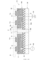
- FIG. 1 is a schematic cross-sectional view illustrating an example of an electrostatic chuck device according to a first embodiment.
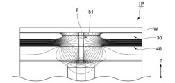
- FIG. 2 is a diagram showing equipotential lines of an electrostatic chuck device of a comparative example.
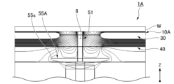
- FIG. 3 is a diagram showing equipotential lines of the electrostatic chuck device of the embodiment.
- FIG. 4 is a schematic cross-sectional view illustrating an example of an electrostatic chuck device according to the second embodiment.
- FIG. 5 is a schematic cross-sectional view of an electrostatic chuck device according to a first modified example of the embodiment.
- FIG. 6 is a schematic cross-sectional view of an electrostatic chuck device according to a second modified example of the embodiment.
- FIG. 1 is a schematic cross-sectional view showing an example of an electrostatic chuck device according to the present embodiment.
- the electrostatic chuck device 1A shown in FIG. 1 is preferably disposed in a vacuum chamber of a plasma processing device with a mounting surface 11a on which a wafer (plate-shaped sample) W is placed facing upward.
- a Z-axis is shown to explain the reference of the electrostatic chuck device.
- the Z-axis direction is, for example, a vertical direction.
- the central axis O of the mounting surface 11a is parallel to the Z-axis. Note that the arrangement of the electrostatic chuck device 1A with respect to the vertical direction is one example, and other arrangements may be used.
- the electrostatic chuck device 1A includes an electrostatic chuck plate (electrostatic chuck member) 10A that adsorbs and supports a plate-shaped sample such as a wafer W, and a base 20 that supports the electrostatic chuck plate 10A.
- an electrostatic chuck plate (electrostatic chuck member) 10A that adsorbs and supports a plate-shaped sample such as a wafer W, and a base 20 that supports the electrostatic chuck plate 10A.
- the base 20 is made of a thick disk-shaped member, for example, a metal member.
- the base 20 supports the electrostatic chuck plate 10A from the lower side (opposite the mounting surface 11a).
- the material constituting the base 20 can be arbitrarily selected, and for example, any metal having excellent thermal conductivity, electrical conductivity, and workability, or a composite material containing these metals, can be preferably used without any particular limitation.
- aluminum, aluminum alloy, copper, copper alloy, stainless steel, etc. are preferably used.
- the base 20 of this embodiment may have an arbitrarily selected structure, and may be, for example, a water-cooled base having a flow path (not shown) for circulating a liquid coolant such as water inside.
- the coolant may be a gas such as He gas or N2 gas.
- the upper surface 20t of the base 20 is adhered to the lower surface 11b of the dielectric substrate 11 via an adhesive layer 25.
- the material forming the adhesive layer 25 can be selected arbitrarily, and may be, for example, a heat-resistant resin such as polyimide resin, silicone resin, or epoxy resin, or an insulating sheet- or film-shaped adhesive resin.
- the electrostatic chuck plate 10A includes a dielectric substrate 11, a cylindrical member 51, an attraction electrode 30, a bias electrode 40, and a shield layer 55A.
- the cylindrical member 51, the attraction electrode 30, the bias electrode 40, and the shield layer 55A are each embedded in the dielectric substrate 11.
- the dielectric substrate 11 is a plate-like member having a circular or nearly circular shape in a plan view.
- the thickness direction of the dielectric substrate 11 may be simply referred to as the "thickness direction".
- the electrostatic chuck device will be described with the side in the thickness direction on which the wafer W is mounted being referred to as the "upper side” and the opposite side being referred to as the "lower side”.
- the "upper side” and the “lower side” indicate an example of the position of the electrostatic chuck device when in use, and do not limit the position of the electrostatic chuck device when in use.
- the dielectric substrate 11 is preferably made of a composite sintered body that has mechanical strength and is resistant to corrosive gases and their plasma.
- the dielectric material that constitutes the dielectric substrate 11 ceramics that have mechanical strength and are resistant to corrosive gases and their plasma are preferably used.
- the ceramics that constitute the dielectric substrate 11 for example, aluminum oxide sintered body, aluminum nitride sintered body, aluminum oxide-silicon carbide composite sintered body, etc. are preferably used.
- the upper surface of the dielectric substrate 11 is provided with a mounting surface 11a on which the wafer W is placed. That is, the dielectric substrate 11 is provided with the mounting surface 11a on which the wafer W is placed.
- a plurality of protrusions 12 are formed at predetermined intervals on the upper surface of the dielectric substrate 11.
- the tip surfaces of the plurality of protrusions 12 form the mounting surface 11a.
- the dielectric substrate 11 is provided with recesses (valleys) 13 between adjacent protrusions 12, which are recessed downward from the mounting surface 11a.
- the bottom surface 13b of the recesses 13 faces upward (towards the wafer W).
- the dielectric substrate 11 is provided with a gas hole 8.
- the gas hole 8 penetrates the dielectric substrate 11 in the thickness direction.
- the gas hole 8 is circular when viewed in the thickness direction.
- the gas hole 8 is connected to a gas supply device (not shown).
- the gas hole 8 supplies a cooling gas such as helium (He) to the space between the wafer W placed on the mounting surface 11a and the bottom surface 13b of the recess 13.
- the supplied cooling gas cools the wafer W placed on the mounting surface 11a.
- a cooling gas such as helium (He)
- the cylindrical member 51 has a cylindrical shape extending in the thickness direction.
- the upper end of the cylindrical member 51 is, for example, annular in plan view.
- the radial direction centered on the cylindrical member 51 may be simply referred to as the "radial direction”
- the circumferential direction centered on the cylindrical member 51 may be simply referred to as the "circumferential direction”.
- the cylindrical member 51 of this embodiment is made of a material having electrical conductivity.
- electrical conductivity means that the electrical resistivity is 0.5 ⁇ m or less. Therefore, the cylindrical member is made of a material having a resistivity of 0.5 ⁇ m or less.
- the preferred range of electrical resistivity of the material constituting the cylindrical member 51 can be selected as necessary, and includes, but is not limited to, 1.0 ⁇ 10 ⁇ 8 to 1.0 ⁇ 10 ⁇ 3 ⁇ m, 1.0 ⁇ 10 ⁇ 8 to 1.0 ⁇ 10 ⁇ 6 ⁇ m, 1.0 ⁇ 10 ⁇ 7 to 1.0 ⁇ 10 ⁇ 4 ⁇ m, 1.0 ⁇ 10 ⁇ 5 to 1.0 ⁇ 10 ⁇ 3 ⁇ m, 1.0 ⁇ 10 ⁇ 4 to 1.0 ⁇ 10 ⁇ 2 ⁇ m, and 1.0 ⁇ 10 ⁇ 3 to 0.5 ⁇ m.
- the material forming the lower cylindrical member 51 can be selected arbitrarily, and includes, but is not limited to, molybdenum, tungsten, tantalum, carbon, or compounds containing these, and ceramics.
- the cylindrical member 51 surrounds the gas hole 8 from the radial outside.
- the cylindrical member 51 is disposed within a hole in the dielectric substrate 11, and the outer surface of the cylindrical member 51 may be in contact with the dielectric substrate 11, or may be via an adhesive or the like.
- no other members are disposed inside the cylindrical member 51, and the inner surface of the cylindrical member 51 forms the inner surface of the gas hole 8.
- other cylindrical members such as insulating insulators may be disposed inside the cylindrical member 51. In this case, the inner surface of the insulator forms the gas hole 8.
- the cylindrical member 51 is positioned so as to penetrate the bottom surface 13b of the recess 13 of the dielectric substrate 11 and the lower surface 11b of the dielectric substrate 11. Therefore, the upper end 51t of the cylindrical member 51 in this embodiment is positioned at approximately the same position as the bottom surface 13b in the thickness direction and is exposed upward from the bottom surface 13b. In addition, the lower end 51b of the cylindrical member 51 is positioned at approximately the same position as the lower surface 11b in the thickness direction.
- the chucking electrode 30, the bias electrode 40, and the shield layer 55A are electrodes and conductive members embedded in layers in the dielectric substrate 11.
- the chucking electrode 30, the bias electrode 40, and the shield layer 55A are conductive. That is, the chucking electrode 30, the bias electrode 40, and the shield layer 55A are made of a material having a resistivity of 0.5 ⁇ m or less.
- the chucking electrode 30, the bias electrode 40, and the shield layer 55A are arranged in this order from the top to the bottom in the dielectric substrate 11.
- the suction electrode 30 is located inside the dielectric substrate 11.
- the suction electrode 30 extends in a layer shape along a plane perpendicular to the thickness direction of the dielectric substrate 11.
- the suction electrode 30 may have any shape that is selected.
- the suction electrode 30 is preferably provided with a first hole 30a through which the tubular member 51 passes.
- the inner diameter of the first hole 30a is sufficiently larger than the outer diameter of the tubular member 51.
- the inner edge of the first hole 30a is disposed at a distance from the outer peripheral surface of the tubular member 51. Due to the provision of the first hole 30a, the suction electrode 30 and the tubular member 51 do not come into contact with each other.
- the suction electrode 30 is disposed below the mounting surface 11a and the bottom surface 13b at a predetermined distance from these.
- the suction electrode 30 is connected to the DC power source 101 via the first power supply 31 extending downward.
- the suction electrode 30 generates an electrostatic suction force by the DC current supplied from the DC power source 101, and suctions the wafer W to the mounting surface 11a.
- the suction electrode 30 is not limited to a monopolar suction electrode, and may be a bipolar suction electrode consisting of two electrodes that are semicircular in plan view.
- the suction electrode 30 may be provided only in a portion of the circumferential direction centered on the cylindrical member 51 when viewed from the thickness direction.
- the suction electrode 30 may be provided in a plurality of locations spaced apart from each other in the circumferential direction centered on the cylindrical member 51 when viewed from the thickness direction.
- the bias electrode 40 is disposed below the chucking electrode 30 (opposite the mounting surface 11a) and spaced apart from the chucking electrode 30.
- the bias electrode 40 extends in a layer shape along a plane perpendicular to the thickness direction of the dielectric substrate 11.
- the bias electrode 40 may have any shape that can be selected.
- the bias electrode 40 is connected to the AC power source 102 via a second power supply 41 that extends downward.
- the bias electrode 40 is preferably provided with a second hole 40a through which the cylindrical member 51 passes, and a third hole 40h through which the first power supply 31 passes.
- the inner diameter of the second hole 40a is sufficiently larger than the outer diameter of the cylindrical member 51.
- the inner edge of the second hole 40a is disposed at a distance from the outer peripheral surface of the cylindrical member 51.
- the inner diameter of the second hole 40a is approximately equal to the inner diameter of the first hole 30a.
- the inner diameter of the third hole 40h is sufficiently larger than the outer diameter of the first power supply 31.
- the inner edge of the third hole 40h is disposed at a distance from the outer peripheral surface of the first power supply 31.
- the shapes of the second hole 40a and the third hole 40h can be selected arbitrarily, but may be, for example, circular in a plan view.
- the outer periphery 40b of the bias electrode 40 and the outer periphery 30b of the adsorption electrode 30 are positioned at approximately the same position when viewed from the thickness direction.
- the bias electrode 40 is positioned so as to cover almost the entire adsorption electrode 30 from below. Note that it is sufficient that at least a portion of the bias electrode 40 overlaps with the adsorption electrode 30 when viewed from the thickness direction. In other words, at least a portion of the bias electrode 40 overlaps with the adsorption electrode 30 when viewed from the thickness direction. In the bias electrode 40 of this embodiment, the entirety of the bias electrode 40 overlaps with the adsorption electrode 30 when viewed from the thickness direction.
- the shield layer 55A is disposed inside the dielectric substrate 11 below the chucking electrode 30 and the bias electrode 40 (on the side opposite the mounting surface 11a) with a gap therebetween.
- the shield layer 55A extends in layers along a plane perpendicular to the thickness direction of the dielectric substrate 11.
- the shield layer 55A contacts the outer peripheral surface of the cylindrical member 51 and is electrically connected to the cylindrical member 51.
- the shield layer 55A extends radially outward from the outer peripheral surface of the cylindrical member 51.
- the shield layer 55A is formed in a flange shape extending in a circumferential direction.
- the shield layer 55A may have any shape that is selected arbitrarily.
- the shield layer 55A is preferably a continuous annular shape, but may have any other shape.
- the shield layer 55A may be composed of multiple parts having any shape that is selected arbitrarily, such as a fan shape or a roughly fan shape.
- the shield layer 55A may be provided only in a part of the circumferential direction.
- the shield layer 55A may be provided as a shield layer 55A consisting of multiple parts arranged at intervals in the circumferential direction.
- the multiple shield layers 55A may extend radially from the outer peripheral surface of the cylindrical member 51.
- the number of the portions of the shield layer 55A may be, for example, 3 to 6, 6 to 12, 12 to 24, or 24 to 48.
- they may have the same shape and size. The distance between adjacent portions may be selected arbitrarily.
- the outer edge 55s located at the radially outer end of the shield layer 55A entirely overlaps the bias electrode 40 when viewed in the thickness direction.
- the attraction electrode 30, the bias electrode 40, and the shield layer 55A are formed of any material, but are preferably composed of a composite of an insulating material and a conductive material.
- the insulating material contained in this composite is not particularly limited, but is preferably at least one selected from the group consisting of aluminum oxide (Al 2 O 3 ), aluminum nitride (AlN), silicon nitride (Si 3 N 4 ), yttrium (III) oxide (Y 2 O 3 ), yttrium aluminum garnet (YAG) and SmAlO 3.
- the conductive material contained in the composite is preferably at least one selected from the group consisting of molybdenum carbide (Mo 2 C), molybdenum (Mo), tungsten carbide (WC), tungsten (W), tantalum carbide (TaC), tantalum (Ta), silicon carbide (SiC), carbon black, carbon nanotubes and carbon nanofibers.
- Mo 2 C molybdenum carbide
- Mo molybdenum
- Mo molybdenum
- Mo molybdenum
- WC molybdenum
- W tungsten
- TaC tantalum carbide
- Ta tantalum
- SiC silicon carbide
- carbon black carbon nanotubes and carbon nanofibers.
- the attraction electrode 30, the bias electrode 40, and the shield layer 55A may be made of the same material or different materials.
- the cylindrical member 51 may be formed from the same material as the shield layer 55A, or may be formed integrally with the shield layer 55A. Also, the cylindrical member 51 may be formed from a material different from that of the shield layer 55A. For example, the cylindrical member 51 may be made of a metal material and may be joined to the shield layer 55A on its outer circumferential surface.
- the attraction electrode 30, bias electrode 40, and shield layer 55A may be formed in advance into a predetermined shape, or may be formed by three-dimensional printing, deposition, or the like.
- the attraction electrode 30, bias electrode 40, and shield layer 55A may be embedded in each layer in sequence as the dielectric substrate 11 is formed by layering the layers in multiple steps.
- the present inventors have focused on the fact that discharge due to ionization of the cooling gas is likely to occur when the potential difference in the thickness direction in the gas hole 8 between the lower surface of the wafer W and the upper surface of the base 20 is large.
- the present inventors have attempted to reduce the potential difference in the gas hole 8, and have come up with the configurations according to each embodiment and its modified examples.
- the chucking electrode 30 and the bias electrode 40 are arranged inside the dielectric substrate 11. Therefore, a potential difference occurs in each part of the dielectric substrate 11 due to the voltage applied to these electrodes 30, 40.
- the electrostatic chuck plate 10A of this embodiment has a conductive cylindrical member 51 that surrounds the gas hole 8 of the dielectric substrate 11. With this configuration, since the gas hole 8 is surrounded by the conductive cylindrical member 51, a large potential difference is unlikely to occur in the gas hole 8, and the discharge of the cooling gas in the gas hole 8 can be suppressed.
- the cylindrical member 51 is arranged radially inward of the electrostatic chuck plate 10A with respect to the chucking electrode 30 and the bias electrode 40. Therefore, it is possible to suppress the electric field directed radially inward from the chucking electrode 30 and the bias electrode 40 from reaching the inside of the gas hole 8.
- the electrostatic chuck plate 10A of this embodiment is disposed inside the dielectric substrate 11 on the opposite side (lower side) of the mounting surface 11a side with respect to the chucking electrode 30 and the bias electrode 40, and has a conductive shield layer 55A extending from the outer circumferential surface of the cylindrical member 51 to the outside in the radial direction centered on the cylindrical member 51.
- the electric field is formed avoiding the shield layer 55A, and the potential difference is less likely to become large below the cylindrical member 51.
- FIGS. 2 and 3 are diagrams showing the results of a simulation to demonstrate the superiority of the electrostatic chuck device 1A of this embodiment.
- FIG. 2 shows an electrostatic chuck device 1P of a comparative example that does not have a shield layer 55A.
- FIG. 3 shows an electrostatic chuck device 1A of an example of this embodiment, which has a shield layer 55A compared to the electrostatic chuck device 1A of the comparative example.
- FIGS. 2 and 3 show schematic diagrams showing the results of a simulation of the equipotential lines of the electric field caused by the chucking electrode 30 and the bias electrode 40.
- the equipotential lines are concentrated and arranged vertically on the lower side of the cylindrical member 51, and it can be seen that the potential difference is large on the lower side of the cylindrical member 51.
- the electrostatic chuck device 1A of the embodiment shown in FIG. 3 most of the equipotential lines coming out from the end of the bias electrode 40 extend along the upper surface of the shield layer 55A and the inner peripheral surface of the cylindrical member 51 to the upper end of the electrostatic chuck plate 10A.
- some of the equipotential lines coming out from the end of the bias electrode 40 extend so as to largely detour around the outside of the outer edge 55s of the shield layer 55A and pass under the cylindrical member 51.
- the number of equipotential lines arranged on the lower side of the cylindrical member 51 in the electrostatic chuck device 1A of the embodiment shown in FIG. 3 is smaller than the number of equipotential lines arranged on the lower side of the cylindrical member 51 in the electrostatic chuck device 1P of the comparative example shown in FIG. 2. From this, it can be seen that in the electrostatic chuck device 1A of the embodiment shown in FIG. 3, the potential difference on the lower side of the cylindrical member 51 is small.
- the shield layer 55A of this embodiment is disposed on the opposite side (lower side) of the mounting surface 11a with respect to the adsorption electrode 30 and the bias electrode 40. That is, when viewed from the cross section, the distance from the mounting surface 11a to the shield layer 55A is greater than the distance from the mounting surface 11a to the adsorption electrode 30 and the bias electrode 40. With this configuration, the shield layer 55A can be disposed between the adsorption electrode 30 and the bias electrode 40 and the lower end of the cylindrical member 51 in the thickness direction. With this configuration, as shown in FIG.
- the equipotential lines extending from the ends of the adsorption electrode 30 and the bias electrode 40 can be largely detoured at a position above the lower end of the cylindrical member 51, and as a result, as shown in FIG. 2, the equipotential lines can be prevented from being concentrated and disposed on the lower side of the cylindrical member 51. As a result, the potential difference on the lower side of the cylindrical member 51 can be effectively prevented from becoming large.
- the electric field formed by applying voltage to the attraction electrode 30 and the bias electrode 40 reaches the upper side of the dielectric substrate 11 without being blocked by the shield layer 55A, allowing the electric field to act effectively on the upper side of the dielectric substrate 11.
- the shield layer 55A overlaps with the bias electrode 40 when viewed in the thickness direction.
- the equipotential lines extending from the end of the bias electrode 40 can be more reliably diverted, and the potential difference below the cylindrical member 51 can be effectively prevented from increasing.
- the length (distance) of the portion where the shield layer 55A overlaps with the bias electrode 40 in a plan view can be selected arbitrarily.
- the length of the overlapping portion may be, for example, 0 to 0.1 times, 0.1 to 0.5 times, 0.3 to 0.8 times, or 0.5 to 1.0 times the length (distance) from the cylindrical member 51 to the radial end of the shield layer 55A, but is not limited to these examples.
- the shield layer 55A does not have to overlap with the bias electrode 40.
- the length (distance) from the cylindrical member 51 to the radial end of the shield layer 55A can be selected arbitrarily.
- the diameter of the shield layer 55A may be 0.5 to 2 mm, 1 to 3 mm, 2 to 5 mm, 4 to 8 mm, or 5 to 10 mm, but is not limited to these examples.
- the shield layer 55A is formed in a flange shape that extends annularly in the circumferential direction around the cylindrical member 51.
- the entire outer edge 55s of the shield layer 55A overlaps with the bias electrode 40.
- the upper end (one end) 51t of the cylindrical member 51 extends to the mounting surface 11a side of the dielectric substrate 11, and the lower end (other end) 51b of the cylindrical member 51 extends to the bottom surface 11b facing the opposite side to the mounting surface 11a side of the dielectric substrate 11.
- “extending to the mounting surface 11a side of the dielectric substrate 11” means extending to the end face (bottom surface 13b in this embodiment) on the mounting surface 11a side of the dielectric substrate 11.
- [Second embodiment] 4 is a cross-sectional view of an electrostatic chuck device according to the second embodiment.
- An electrostatic chuck device 1B according to the present embodiment is different from the electrostatic chuck device 1A described above in that the configuration of a cylindrical member 52 is different, and the other configuration is common to the electrostatic chuck device 1A. Therefore, the following mainly describes the cylindrical member 52, and a description of the configuration common to the electrostatic chuck device 1A will be omitted.
- the electrostatic chuck device 1B shown in FIG. 4 includes an electrostatic chuck plate 10B and a base 20.
- the electrostatic chuck plate 10B includes a dielectric substrate 11, a cylindrical member 52, an adsorption electrode 30, a bias electrode 40, and a shield layer 55A.
- the tubular member 52 is cylindrical and extends in the thickness direction, and is arranged so as to penetrate the bottom surface 13b of the recess 13 of the dielectric substrate 11 and the base bottom surface 20b of the base 20.
- the upper end 52t of the tubular member 52 is arranged at the same height as the bottom surface 13b in the thickness direction, and is exposed upward from the bottom surface 13b.
- the lower end (other end) 52b of the tubular member 52 is arranged at the same height as the base bottom surface 20b in the thickness direction, and is exposed downward from the base bottom surface 20b.
- the cylindrical member 52 of this embodiment is grounded via a ground wire 103. This configuration prevents potential differences from occurring in the thickness direction inside the cylindrical member 52, and can suppress abnormal discharges inside the gas hole 8.
- the electrostatic chuck device 1B of this embodiment includes a base 20 that supports the electrostatic chuck plate 10B from the side opposite the mounting surface 11a.
- the cylindrical member 52 contacts the base 20. With this configuration, no gap is created between the cylindrical member 52 and the base 20. This makes it possible to prevent the electric field from concentrating below the cylindrical member 52 and above the base 20. This makes it possible to prevent the potential difference from increasing in the region inside the gas hole 8, below the cylindrical member 52, and above the base 20, and effectively suppresses discharge inside the gas hole 8.
- the gas hole 8 penetrates the base 20 in the thickness direction.
- the upper end (one end) 52t of the cylindrical member 52 extends to the mounting surface 11a side of the dielectric substrate 11.
- the lower end (other end) 52b of the cylindrical member 52 extends to the underside facing the opposite side to the mounting surface 11a side of the base 20.
- (First Modification of the Embodiment) 5 is a cross-sectional view of an electrostatic chuck device according to a first modified example of the embodiment.
- the electrostatic chuck device 1C of this modified example is different from the electrostatic chuck device 1A of the first embodiment described above only in the configuration of the cylindrical member. Note that the same components as those of the first embodiment described above are denoted by the same reference numerals, and the description thereof will be omitted.
- the electrostatic chuck device 1C in this modified example includes an electrostatic chuck plate 10C and a base 20, similar to the above-described embodiment.
- the electrostatic chuck plate 10C also includes a dielectric substrate 11, a cylindrical member 53, an adsorption electrode 30, a bias electrode 40, and a shield layer 55A.
- the cylindrical member 53 of this modified example surrounds the gas hole 8.
- the upper end (one end) 53t of the cylindrical member 53 is disposed at the same height as the bottom surface 13b in the thickness direction.
- the lower end (other end) 53b of the cylindrical member 53 is disposed above the lower surface of the dielectric substrate 11 in the thickness direction.
- This lower end 53b is formed at the same height as the lower surface of the shield layer 55A in the thickness direction.
- the cylindrical member 53 and the shield layer 55A do not contact the adhesive layer 25.
- the bias electrode 40 and the shield layer 55A are provided, making it possible to suppress abnormal discharge inside the gas hole 8.
- (Second Modification of the Embodiment) 6 is a cross-sectional view of an electrostatic chuck device according to a second modified example of the embodiment.
- the electrostatic chuck device 1D of this modified example is different from the electrostatic chuck device 1A of the first embodiment described above only in the configuration of a shield layer 55D. Note that the same components as those of the first embodiment described above are denoted by the same reference numerals, and the description thereof will be omitted.
- the electrostatic chuck device 1D in this modification includes an electrostatic chuck plate 10D and a base 20, similar to the above-described embodiment.
- the electrostatic chuck plate 10D also includes a dielectric substrate 11, a cylindrical member 51, an adsorption electrode 30, a bias electrode 40, and a shield layer 55D.
- the lower surface of the shield layer 55D is formed at the same height as the lower surface 11b of the dielectric substrate 11, and is in contact with the adhesive layer 25.
- the bias electrode 40 and the shield layer 55D are provided, making it possible to suppress abnormal discharge inside the gas hole 8.
Landscapes
- Physics & Mathematics (AREA)
- Engineering & Computer Science (AREA)
- Plasma & Fusion (AREA)
- Chemical & Material Sciences (AREA)
- Analytical Chemistry (AREA)
- Container, Conveyance, Adherence, Positioning, Of Wafer (AREA)
- Jigs For Machine Tools (AREA)
- Drying Of Semiconductors (AREA)
Abstract
Description
本願は、2023年6月19日に、日本に出願された特願2023-100070号に基づき優先権を主張し、その内容をここに援用する。
以下に述べられる特徴は、必要に応じて2つ以上を組み合わせることも好ましい。
[1] 板状試料が載置される載置面および厚さ方向に貫通するガス孔が設けられる板状の誘電体基板と、前記誘電体基板の内部に配置される吸着電極と、前記誘電体基板の内部に配置されるバイアス電極と、前記ガス孔を囲む導電性の筒状部材と、前記誘電体基板の内部において前記吸着電極および前記バイアス電極に対して前記載置面側とは反対側に配置され、前記筒状部材の外周面から前記筒状部材を中心とする径方向の外側に延びる導電性のシールド層と、を備える、静電チャック部材。
[2] 前記厚さ方向から見て、前記シールド層は、少なくとも一部が前記バイアス電極に重なる、[1]に記載の静電チャック部材。
[3] 前記シールド層は、前記筒状部材を中心とする周方向に環状に延びる鍔状に形成される、[1]または[2]に記載の静電チャック部材。
[4] 前記厚さ方向から見て、前記シールド層の外縁の全体が、前記バイアス電極に重なる、[3]に記載の静電チャック部材。
[5] 前記筒状部材の一端は、前記誘電体基板の前記載置面側まで延び、前記筒状部材の他端は、前記誘電体基板の前記載置面側とは反対側を向く下面まで延びる、[1]~[4]の何れか一項に記載の静電チャック部材。
[6] 前記筒状部材は、接地される、[1]~[5]の何れか一項に記載の静電チャック部材。
[7] [1]~[6]の何れか一項に記載の静電チャック部材と、前記静電チャック部材を前記載置面の反対側から支持する基台と、を備え、前記筒状部材は、前記基台に接触する、静電チャック装置。
[8] 前記ガス孔は、前記基台を前記厚さ方向に貫通し、前記筒状部材の一端は、前記誘電体基板の前記載置面側まで延び、前記筒状部材の他端は、前記基台の前記載置面側とは反対側を向く下面まで延びる、[7]に記載の静電チャック装置。
また、本実施の形態は、発明の趣旨をより良く理解させるために具体的に説明するものであり、特に指定のない限り、本発明を限定するものではない。例えば、特に制限のない限り、材料、量、種類、数、サイズ、形、位置、比率、温度等の条件等を、必要に応じて変更、追加および省略してもよい。以下に述べる実施形態間において、互いの好ましい例を交換したり、共有したりしてもよい。以下に述べる第1実施形態~第2実施形態や変形例は、問題のない限り互いに好ましい特徴や条件を共有してもよい。
(静電チャック装置全体)
図1は、本実施形態の静電チャック装置の例を示す概略断面図である。
図1に示す静電チャック装置1Aは、例えば、ウエハ(板状試料)Wが載置される載置面11aを上側に向けた状態でプラズマ処理装置の真空容器内に好ましく配置される。
なお、各図には、静電チャック装置の基準を説明するためにZ軸を示す。Z軸方向は、例えば、鉛直方向である。載置面11aの中心軸Oは、Z軸に平行である。なお、鉛直方向に対する静電チャック装置1Aの配置形態は一例であり、他の配置形態であってもよい。
基台20は、厚さのある円板状の部材、例えば金属部材からなる。基台20は、静電チャックプレート10Aを下側(載置面11aの反対側)から支持する。基台20を構成する材料としては任意に選択でき、例えば、熱伝導性、導電性、加工性に優れた金属、またはこれらの金属を含む複合材であれば特に制限はなく好ましく使用できる。例えば、アルミニウム、アルミニウム合金、銅、銅合金、ステンレス鋼等が好適に用いられる。本実施形態の基台20は任意に選択できる構造を有してよく、例えば内部に水等の液体の冷媒を循環させる流路(図示無し)を有する水冷ベースであってもよい。冷媒はHeガス、N2ガス等のガスであってもよい。
静電チャックプレート10Aは、誘電体基板11と、筒状部材51と、吸着電極30と、バイアス電極40と、シールド層55Aと、を有する。筒状部材51、吸着電極30、バイアス電極40、およびシールド層55Aは、それぞれ誘電体基板11に埋め込まれている。
誘電体基板11は、平面視円形又は略円形の板状部材である。本明細書において、誘電体基板11の厚さ方向を単に「厚さ方向」と呼ぶ場合がある。また、本明細書において、厚さ方向のうち、ウエハWが搭載される側を「上側」とし、その反対側を「下側」として、静電チャック装置を説明する。本明細書における「上側」および「下側」は、静電チャック装置の使用時の姿勢の一例を示すものであり、静電チャック装置の使用時の姿勢を限定するものではない。
筒状部材51は、厚さ方向に延びる円筒形状を有する。筒状部材51の上端は例えば平面視で円環状である。以下の説明において、筒状部材51を中心とする径方向を単に「径方向」と呼び、筒状部材51を中心とする周方向を単に「周方向」と呼ぶ場合がある。本実施形態の筒状部材51は、導電性を有する材料から構成される。なお、ここで、「導電性」とは、電気抵抗率が0.5Ω・m以下であることを意味する。したがって、筒状部材は、抵抗率が0.5Ω・m以下の部材からなる。筒状部材51を構成する材料が有する電気抵抗率の好ましい範囲としては、必要に応じて選択できるが、1.0×10⁻⁸~1.0×10⁻³Ω・mや、1.0×10⁻⁸~1.0×10⁻⁶Ω・mや、1.0×10⁻⁷~1.0×10⁻⁴Ω・mや、1.0×10⁻⁵~1.0×10⁻³Ω・mや、1.0×10⁻⁴~1.0×10⁻²Ω・mや、1.0×10⁻³~0.5Ω・mが挙げられるが、これら例のみに限定されない。下筒状部材51を形成する材料は任意に選択でき、例えば、モリブデンやタングステンやタンタルや炭素、またはそれらを含む化合物およびセラミックなどが挙げられるが、これら例のみに限定されない。
吸着電極30、バイアス電極40、およびシールド層55Aは、誘電体基板11に層状に埋設される電極および導電性部材である。吸着電極30、バイアス電極40、およびシールド層55Aは、導電性を有する。すなわち、吸着電極30、バイアス電極40、およびシールド層55Aは、抵抗率が0.5Ω・m以下の材料からなる。吸着電極30、バイアス電極40、およびシールド層55Aは、誘電体基板11内で、上側から下側に向かって、この順で配置されている。
一般的に、載置面11aに搭載されるウエハWは、上面にエッチングガスが衝突することでウエハWの下面側から二次電子を放出することが知られている。また、このような二次電子の放出現象の発生頻度は、近年のエッチングのハイパワー化に伴って高まっている。ウエハWの下面側に放出される二次電子がガス孔8の内部に侵入すると、ガス孔8内で冷却ガスが電離してガス孔8内で放電を引き起こす場合がある。本発明者らは、冷却ガスの電離に伴う放電は、ウエハWの下面から基台20の上面までの間の、ガス孔8内の厚さ方向の電位差が大きい場合に発生しやすい点に着目した。本発明者らは、ガス孔8内の電位差を低減させることを試みた結果、各実施形態およびその変形例に係る構成を想到するに至った。
図4は、第2実施形態の静電チャック装置の断面図である。本実施形態の静電チャック装置1Bでは、上記静電チャック装置1Aと比較して筒状部材52の構成が異なり、他の構成は静電チャック装置1Aと共通する。そのため、主として筒状部材52の説明を行い、静電チャック装置1Aと共通する構成については説明を省略する。
図5は、実施形態の第1変形例の静電チャック装置の断面図である。本変形例の静電チャック装置1Cは、上述の第1実施形態の静電チャック装置1Aと比較して、筒状部材の構成のみが異なる。なお、上述の第1実施形態と同一態様の構成要素については、同一符号を付し、その説明を省略する。
図6は、実施形態の第2変形例の静電チャック装置の断面図である。本変形例の静電チャック装置1Dは、上述の第1実施形態の静電チャック装置1Aと比較して、シールド層55Dの構成のみが異なる。なお、上述の第1実施形態と同一態様の構成要素については、同一符号を付し、その説明を省略する。
8…ガス孔
10A~10D…静電チャックプレート(静電チャック部材)
11…誘電体基板
11a…載置面
11b…下面
12 突起部
13 凹部
13b 底面
20…基台
20b…基台底面
20t 上面
25 接着層
30…吸着電極
30a 第1孔部
30b 外周縁
40…バイアス電極
40a 第2孔部
40b 外周縁
40h 第3孔部
41 第2給電部
51~53…筒状部材
51b、52b、53b 下端(他端)
51t、52t、53t 上端(一端)
55A、55D…シールド層
55s 外縁
101 直流電流
102 交流電流
103 接地線
O 中心軸
W…ウエハ(板状試料)
Claims (8)
- 板状試料が載置される載置面および厚さ方向に貫通するガス孔が設けられる板状の誘電体基板と、
前記誘電体基板の内部に配置される吸着電極と、
前記誘電体基板の内部に配置されるバイアス電極と、
前記ガス孔を囲む導電性の筒状部材と、
前記誘電体基板の内部において前記吸着電極および前記バイアス電極に対して前記載置面側とは反対側に配置され、前記筒状部材の外周面から前記筒状部材を中心とする径方向の外側に延びる導電性のシールド層と、を備える、
静電チャック部材。 - 前記厚さ方向から見て、前記シールド層は、少なくとも一部が前記バイアス電極に重なる、
請求項1に記載の静電チャック部材。 - 前記シールド層は、前記筒状部材を中心とする周方向に環状に延びる鍔状に形成される、
請求項1に記載の静電チャック部材。 - 前記厚さ方向から見て、前記シールド層の外縁の全体が、前記バイアス電極に重なる、請求項3に記載の静電チャック部材。
- 前記筒状部材の一端は、前記誘電体基板の前記載置面側まで延び、
前記筒状部材の他端は、前記誘電体基板の前記載置面側とは反対側を向く下面まで延びる、
請求項1に記載の静電チャック部材。 - 前記筒状部材は、接地される、
請求項1に記載の静電チャック部材。 - 請求項1~6の何れか一項に記載の静電チャック部材と、
前記静電チャック部材を前記載置面の反対側から支持する基台と、を備え、
前記筒状部材は、前記基台に接触する、
静電チャック装置。 - 前記ガス孔は、前記基台を前記厚さ方向に貫通し、
前記筒状部材の一端は、前記誘電体基板の前記載置面側まで延び、
前記筒状部材の他端は、前記基台の前記載置面側とは反対側を向く下面まで延びる、請求項7に記載の静電チャック装置。
Priority Applications (2)
| Application Number | Priority Date | Filing Date | Title |
|---|---|---|---|
| CN202480011656.5A CN120660184A (zh) | 2023-06-19 | 2024-05-28 | 静电卡盘部件及静电卡盘装置 |
| KR1020257027686A KR102920602B1 (ko) | 2023-06-19 | 2024-05-28 | 정전 척 부재 및 정전 척 장치 |
Applications Claiming Priority (2)
| Application Number | Priority Date | Filing Date | Title |
|---|---|---|---|
| JP2023100070A JP2025000292A (ja) | 2023-06-19 | 2023-06-19 | 静電チャック部材および静電チャック装置 |
| JP2023-100070 | 2023-06-19 |
Publications (1)
| Publication Number | Publication Date |
|---|---|
| WO2024262256A1 true WO2024262256A1 (ja) | 2024-12-26 |
Family
ID=93935071
Family Applications (1)
| Application Number | Title | Priority Date | Filing Date |
|---|---|---|---|
| PCT/JP2024/019480 Ceased WO2024262256A1 (ja) | 2023-06-19 | 2024-05-28 | 静電チャック部材および静電チャック装置 |
Country Status (5)
| Country | Link |
|---|---|
| JP (1) | JP2025000292A (ja) |
| KR (1) | KR102920602B1 (ja) |
| CN (1) | CN120660184A (ja) |
| TW (1) | TW202501706A (ja) |
| WO (1) | WO2024262256A1 (ja) |
Citations (2)
| Publication number | Priority date | Publication date | Assignee | Title |
|---|---|---|---|---|
| JP2021057526A (ja) * | 2019-10-01 | 2021-04-08 | 東京エレクトロン株式会社 | 載置台及びプラズマ処理装置 |
| JP2023044634A (ja) * | 2021-09-17 | 2023-03-30 | 東京エレクトロン株式会社 | プラズマ処理装置 |
Family Cites Families (5)
| Publication number | Priority date | Publication date | Assignee | Title |
|---|---|---|---|---|
| JP2010182763A (ja) | 2009-02-04 | 2010-08-19 | Hitachi High-Technologies Corp | プラズマ処理装置 |
| US8520360B2 (en) * | 2011-07-19 | 2013-08-27 | Lam Research Corporation | Electrostatic chuck with wafer backside plasma assisted dechuck |
| JP7130359B2 (ja) | 2016-12-05 | 2022-09-05 | 東京エレクトロン株式会社 | プラズマ処理装置 |
| US12300473B2 (en) * | 2019-03-08 | 2025-05-13 | Applied Materials, Inc. | Electrostatic chuck for high bias radio frequency (RF) power application in a plasma processing chamber |
| TW202333191A (zh) | 2021-10-28 | 2023-08-16 | 日商東京威力科創股份有限公司 | 電漿處理裝置及靜電吸盤 |
-
2023
- 2023-06-19 JP JP2023100070A patent/JP2025000292A/ja active Pending
-
2024
- 2024-05-28 KR KR1020257027686A patent/KR102920602B1/ko active Active
- 2024-05-28 CN CN202480011656.5A patent/CN120660184A/zh active Pending
- 2024-05-28 WO PCT/JP2024/019480 patent/WO2024262256A1/ja not_active Ceased
- 2024-06-13 TW TW113121779A patent/TW202501706A/zh unknown
Patent Citations (2)
| Publication number | Priority date | Publication date | Assignee | Title |
|---|---|---|---|---|
| JP2021057526A (ja) * | 2019-10-01 | 2021-04-08 | 東京エレクトロン株式会社 | 載置台及びプラズマ処理装置 |
| JP2023044634A (ja) * | 2021-09-17 | 2023-03-30 | 東京エレクトロン株式会社 | プラズマ処理装置 |
Also Published As
| Publication number | Publication date |
|---|---|
| TW202501706A (zh) | 2025-01-01 |
| CN120660184A (zh) | 2025-09-16 |
| KR20250137671A (ko) | 2025-09-18 |
| JP2025000292A (ja) | 2025-01-07 |
| KR102920602B1 (ko) | 2026-02-02 |
Similar Documents
| Publication | Publication Date | Title |
|---|---|---|
| US11640917B2 (en) | Ground electrode formed in an electrostatic chuck for a plasma processing chamber | |
| US11887877B2 (en) | Electrostatic chuck device | |
| US10153192B2 (en) | Electrostatic chuck device | |
| KR102648014B1 (ko) | 열 초크를 갖는 정전 척 | |
| WO2017069238A1 (ja) | 静電チャック装置 | |
| KR102859371B1 (ko) | 웨이퍼 지지 장치 | |
| WO2019065233A1 (ja) | 静電チャック装置 | |
| KR102920602B1 (ko) | 정전 척 부재 및 정전 척 장치 | |
| WO2025004572A1 (ja) | 静電チャック装置 | |
| JP2025049890A (ja) | 静電チャック部材および静電チャック装置 | |
| JP6140394B2 (ja) | 第2電位に対して第1電位を有する導電面を電気的に絶縁するためのデバイスであって、導電面の周辺端部の点における静電場の値を低減するための手段を含む、デバイス | |
| JP2025084481A (ja) | 静電チャック | |
| JP2024138919A (ja) | 静電チャック | |
| JP7697548B1 (ja) | 静電チャック | |
| US20250246472A1 (en) | Electrostatic chuck | |
| US20260090331A1 (en) | Electrostatic chuck | |
| JP7709480B2 (ja) | 静電チャック | |
| US20260088735A1 (en) | Electrostatic chuck | |
| CN120998854A (zh) | 静电吸盘 | |
| WO2026042585A1 (ja) | 静電チャック部材、および静電チャック装置 | |
| CN121123097A (zh) | 静电吸盘 | |
| KR20250151177A (ko) | 기판 고정 장치 | |
| WO2026042583A1 (ja) | 静電チャック部材、および静電チャック装置 |
Legal Events
| Date | Code | Title | Description |
|---|---|---|---|
| 121 | Ep: the epo has been informed by wipo that ep was designated in this application |
Ref document number: 24825663 Country of ref document: EP Kind code of ref document: A1 |
|
| WWE | Wipo information: entry into national phase |
Ref document number: 202480011656.5 Country of ref document: CN |
|
| ENP | Entry into the national phase |
Ref document number: 1020257027686 Country of ref document: KR Free format text: ST27 STATUS EVENT CODE: A-0-1-A10-A15-NAP-PA0105 (AS PROVIDED BY THE NATIONAL OFFICE) |
|
| WWE | Wipo information: entry into national phase |
Ref document number: 1020257027686 Country of ref document: KR |
|
| WWP | Wipo information: published in national office |
Ref document number: 202480011656.5 Country of ref document: CN |
|
| NENP | Non-entry into the national phase |
Ref country code: DE |