WO2024262192A1 - 積層造形方法及び積層造形装置並びにプログラム - Google Patents
積層造形方法及び積層造形装置並びにプログラム Download PDFInfo
- Publication number
- WO2024262192A1 WO2024262192A1 PCT/JP2024/017768 JP2024017768W WO2024262192A1 WO 2024262192 A1 WO2024262192 A1 WO 2024262192A1 JP 2024017768 W JP2024017768 W JP 2024017768W WO 2024262192 A1 WO2024262192 A1 WO 2024262192A1
- Authority
- WO
- WIPO (PCT)
- Prior art keywords
- modeling
- fiber bundle
- path
- filament
- twisted
- Prior art date
- Legal status (The legal status is an assumption and is not a legal conclusion. Google has not performed a legal analysis and makes no representation as to the accuracy of the status listed.)
- Ceased
Links
Images





Classifications
-
- B—PERFORMING OPERATIONS; TRANSPORTING
- B29—WORKING OF PLASTICS; WORKING OF SUBSTANCES IN A PLASTIC STATE IN GENERAL
- B29C—SHAPING OR JOINING OF PLASTICS; SHAPING OF MATERIAL IN A PLASTIC STATE, NOT OTHERWISE PROVIDED FOR; AFTER-TREATMENT OF THE SHAPED PRODUCTS, e.g. REPAIRING
- B29C64/00—Additive manufacturing, i.e. manufacturing of three-dimensional [3D] objects by additive deposition, additive agglomeration or additive layering, e.g. by 3D printing, stereolithography or selective laser sintering
- B29C64/10—Processes of additive manufacturing
- B29C64/106—Processes of additive manufacturing using only liquids or viscous materials, e.g. depositing a continuous bead of viscous material
- B29C64/118—Processes of additive manufacturing using only liquids or viscous materials, e.g. depositing a continuous bead of viscous material using filamentary material being melted, e.g. fused deposition modelling [FDM]
-
- B—PERFORMING OPERATIONS; TRANSPORTING
- B29—WORKING OF PLASTICS; WORKING OF SUBSTANCES IN A PLASTIC STATE IN GENERAL
- B29C—SHAPING OR JOINING OF PLASTICS; SHAPING OF MATERIAL IN A PLASTIC STATE, NOT OTHERWISE PROVIDED FOR; AFTER-TREATMENT OF THE SHAPED PRODUCTS, e.g. REPAIRING
- B29C64/00—Additive manufacturing, i.e. manufacturing of three-dimensional [3D] objects by additive deposition, additive agglomeration or additive layering, e.g. by 3D printing, stereolithography or selective laser sintering
- B29C64/20—Apparatus for additive manufacturing; Details thereof or accessories therefor
- B29C64/205—Means for applying layers
- B29C64/209—Heads; Nozzles
-
- B—PERFORMING OPERATIONS; TRANSPORTING
- B29—WORKING OF PLASTICS; WORKING OF SUBSTANCES IN A PLASTIC STATE IN GENERAL
- B29C—SHAPING OR JOINING OF PLASTICS; SHAPING OF MATERIAL IN A PLASTIC STATE, NOT OTHERWISE PROVIDED FOR; AFTER-TREATMENT OF THE SHAPED PRODUCTS, e.g. REPAIRING
- B29C64/00—Additive manufacturing, i.e. manufacturing of three-dimensional [3D] objects by additive deposition, additive agglomeration or additive layering, e.g. by 3D printing, stereolithography or selective laser sintering
- B29C64/30—Auxiliary operations or equipment
- B29C64/386—Data acquisition or data processing for additive manufacturing
- B29C64/393—Data acquisition or data processing for additive manufacturing for controlling or regulating additive manufacturing processes
-
- B—PERFORMING OPERATIONS; TRANSPORTING
- B29—WORKING OF PLASTICS; WORKING OF SUBSTANCES IN A PLASTIC STATE IN GENERAL
- B29C—SHAPING OR JOINING OF PLASTICS; SHAPING OF MATERIAL IN A PLASTIC STATE, NOT OTHERWISE PROVIDED FOR; AFTER-TREATMENT OF THE SHAPED PRODUCTS, e.g. REPAIRING
- B29C70/00—Shaping composites, i.e. plastics material comprising reinforcements, fillers or preformed parts, e.g. inserts
- B29C70/04—Shaping composites, i.e. plastics material comprising reinforcements, fillers or preformed parts, e.g. inserts comprising reinforcements only, e.g. self-reinforcing plastics
- B29C70/28—Shaping operations therefor
- B29C70/30—Shaping by lay-up, i.e. applying fibres, tape or broadsheet on a mould, former or core; Shaping by spray-up, i.e. spraying of fibres on a mould, former or core
- B29C70/38—Automated lay-up, e.g. using robots, laying filaments according to predetermined patterns
-
- B—PERFORMING OPERATIONS; TRANSPORTING
- B29—WORKING OF PLASTICS; WORKING OF SUBSTANCES IN A PLASTIC STATE IN GENERAL
- B29C—SHAPING OR JOINING OF PLASTICS; SHAPING OF MATERIAL IN A PLASTIC STATE, NOT OTHERWISE PROVIDED FOR; AFTER-TREATMENT OF THE SHAPED PRODUCTS, e.g. REPAIRING
- B29C70/00—Shaping composites, i.e. plastics material comprising reinforcements, fillers or preformed parts, e.g. inserts
- B29C70/04—Shaping composites, i.e. plastics material comprising reinforcements, fillers or preformed parts, e.g. inserts comprising reinforcements only, e.g. self-reinforcing plastics
- B29C70/28—Shaping operations therefor
- B29C70/30—Shaping by lay-up, i.e. applying fibres, tape or broadsheet on a mould, former or core; Shaping by spray-up, i.e. spraying of fibres on a mould, former or core
- B29C70/38—Automated lay-up, e.g. using robots, laying filaments according to predetermined patterns
- B29C70/382—Automated fiber placement [AFP]
-
- B—PERFORMING OPERATIONS; TRANSPORTING
- B33—ADDITIVE MANUFACTURING TECHNOLOGY
- B33Y—ADDITIVE MANUFACTURING, i.e. MANUFACTURING OF THREE-DIMENSIONAL [3D] OBJECTS BY ADDITIVE DEPOSITION, ADDITIVE AGGLOMERATION OR ADDITIVE LAYERING, e.g. BY 3D PRINTING, STEREOLITHOGRAPHY OR SELECTIVE LASER SINTERING
- B33Y10/00—Processes of additive manufacturing
-
- B—PERFORMING OPERATIONS; TRANSPORTING
- B33—ADDITIVE MANUFACTURING TECHNOLOGY
- B33Y—ADDITIVE MANUFACTURING, i.e. MANUFACTURING OF THREE-DIMENSIONAL [3D] OBJECTS BY ADDITIVE DEPOSITION, ADDITIVE AGGLOMERATION OR ADDITIVE LAYERING, e.g. BY 3D PRINTING, STEREOLITHOGRAPHY OR SELECTIVE LASER SINTERING
- B33Y30/00—Apparatus for additive manufacturing; Details thereof or accessories therefor
-
- B—PERFORMING OPERATIONS; TRANSPORTING
- B33—ADDITIVE MANUFACTURING TECHNOLOGY
- B33Y—ADDITIVE MANUFACTURING, i.e. MANUFACTURING OF THREE-DIMENSIONAL [3D] OBJECTS BY ADDITIVE DEPOSITION, ADDITIVE AGGLOMERATION OR ADDITIVE LAYERING, e.g. BY 3D PRINTING, STEREOLITHOGRAPHY OR SELECTIVE LASER SINTERING
- B33Y50/00—Data acquisition or data processing for additive manufacturing
- B33Y50/02—Data acquisition or data processing for additive manufacturing for controlling or regulating additive manufacturing processes
-
- B—PERFORMING OPERATIONS; TRANSPORTING
- B33—ADDITIVE MANUFACTURING TECHNOLOGY
- B33Y—ADDITIVE MANUFACTURING, i.e. MANUFACTURING OF THREE-DIMENSIONAL [3D] OBJECTS BY ADDITIVE DEPOSITION, ADDITIVE AGGLOMERATION OR ADDITIVE LAYERING, e.g. BY 3D PRINTING, STEREOLITHOGRAPHY OR SELECTIVE LASER SINTERING
- B33Y70/00—Materials specially adapted for additive manufacturing
- B33Y70/10—Composites of different types of material, e.g. mixtures of ceramics and polymers or mixtures of metals and biomaterials
Definitions
- the present invention relates to an additive manufacturing method, an additive manufacturing device, and a program.
- 3D (three-dimensional) printers that use fused deposition modeling, in which resin in a plasticized state by heat is stacked layer by layer along a modeling path, are known as additive manufacturing devices that mold objects with three-dimensional shapes. In addition to being able to mold three-dimensional shapes without the need for molds or jigs, these 3D printers can also mold three-dimensional objects that are difficult to form using conventional injection molding technology.
- the strand described in Patent Document 1 is a filament used as a modeling material in a 3D printer, in which fibers or fiber bundles are impregnated and twisted in a base material whose main component is a thermoplastic resin.
- This increases the flexibility of the filament itself, improving its ease of handling.
- objects created using the filament with a 3D printer have excellent impact strength. In this way, the filament described above makes it possible to easily create objects with excellent impact strength using a 3D printer.
- filaments reinforced with continuous fibers having a twist rate of 10 turns/m to 200 turns/m may have a risk of the reinforcing fiber's spread width decreasing or becoming unstable when the modeling material obtained by heating and melting the filament is discharged along the modeling path from a nozzle (discharge unit) provided in the head unit of the 3D printer. This is particularly evident in certain shapes of modeling paths when the twist rate given to the reinforcing fiber is large.
- the fusion of the modeling materials ejected from the nozzle between adjacent modeling passes is reduced, making it easier for voids to form. This reduces the mechanical strength between the lines and layers of the modeling passes, requiring time and effort such as revising the modeling plan to avoid this reduction in mechanical strength.
- the present invention aims to provide an additive manufacturing method, additive manufacturing device, and program that can create an object without causing a decrease in mechanical strength between the lines and layers of the modeling path.
- the present invention comprises the following configurations.
- a layered manufacturing method in which a modeling material obtained by heating and melting a linear continuous fiber reinforced filament is ejected from a nozzle along a modeling path on a modeling surface to model a curved or bent shape on the modeling surface,
- the continuous fiber reinforced filament includes a substrate including a thermoplastic resin and at least one fiber bundle including continuous fibers impregnated in the substrate and extending in an axial direction;
- the continuous fibers of the fiber bundle are twisted about an axial core of the continuous fiber reinforced filament at 20 turns/m or more and 100 turns/m or less,
- the shaping path on the shaping surface is a path for discharging the shaping material while curving or bending it to the right side toward the front of the shaping direction
- the shaping path is a path for discharging the shaping material while curving or bending it to the left side toward the front of the shaping direction, thereby forming the curved or bent shape.
- An additive manufacturing device including: a head unit that discharges a modeling material obtained by heating and melting a linear continuous fiber reinforced filament from a nozzle; a drive mechanism that moves the nozzle of the head unit relative to a modeling surface; and a control unit that drives the drive mechanism to discharge the modeling material along a set modeling path
- the continuous fiber reinforced filament includes a substrate including a thermoplastic resin and at least one fiber bundle including continuous fibers impregnated in the substrate and extending in an axial direction;
- the continuous fibers of the fiber bundle are twisted about an axial core of the continuous fiber reinforced filament at 20 turns/m or more and 100 turns/m or less,
- the control unit sets the modeling path on the modeling surface to a path in which the modeling material is discharged while curving or bending the fiber bundle to the right side toward the front of the modeling direction when the fiber bundle is Z-twisted, and sets the modeling path to a path in which the modeling material is discharged while curving or bending the fiber bundle
- Additive manufacturing equipment (3) A program for executing an additive manufacturing procedure in which a modeling material obtained by heating and melting a linear continuous fiber reinforced filament is ejected from a nozzle along a modeling path on a modeling surface to model a curved or bent shape on the modeling surface,
- the continuous fiber reinforced filament includes a substrate including a thermoplastic resin and at least one fiber bundle including continuous fibers impregnated in the substrate and extending in an axial direction;
- the continuous fibers of the fiber bundle are twisted about an axial core of the continuous fiber reinforced filament at 20 turns/m or more and 100 turns/m or less,
- the modeling path on the modeling surface is a path for discharging the modeling material while curving or bending it to the right side toward the front of the modeling direction
- the modeling path is a path for discharging the modeling material while curving or bending it to the left side toward the front of the modeling direction, thereby executing a procedure for modeling the curved shape or the bent
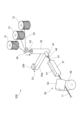
- FIG. 1 is a schematic diagram of an FDM-type additive manufacturing device.
- FIG. 2A is a schematic cross-sectional view of a radial direction perpendicular to the axial direction of the filament.
- FIG. 2B is a side view taken along the axial direction of the filament.
- FIG. 3 is a schematic diagram of a filament manufacturing device.
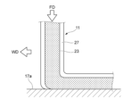
- FIG. 4A is a diagram showing a schematic diagram of a molding material formed by dissolving a filament being ejected onto a molding surface from a nozzle (not shown), and is an explanatory diagram showing a vertical cross section of the filament.
- FIG. 4A is a diagram showing a schematic diagram of a molding material formed by dissolving a filament being ejected onto a molding surface from a nozzle (not shown), and is an explanatory diagram showing a vertical cross section of the filament.
- FIG. 4A is a diagram showing a schematic diagram of a molding material formed by dissolving a filament being ejected onto
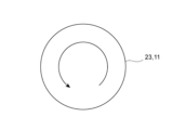
- FIG. 4B is a schematic diagram showing how a modeling material made of molten filaments is ejected onto a modeling surface from a nozzle (not shown), and is a schematic plan view showing a partial cross section of FIG. 4A when viewed in plan.
- FIG. 5 is an explanatory diagram showing a schematic diagram of the twist direction when the reinforcing fibers of the fiber bundles in the filament are Z-twisted.
- FIG. 6 is an explanatory diagram showing a schematic diagram of the twist direction when the reinforcing fibers of the fiber bundles in the filament are S-twisted.
- FIG. 7 is an explanatory diagram showing the direction in which the Z-twisted reinforcing fibers of the fiber bundle in the shaping material rotate in position as the filament is fed at the same nozzle position.
- FIG. 5 is an explanatory diagram showing a schematic diagram of the twist direction when the reinforcing fibers of the fiber bundles in the filament are Z-twisted.
- FIG. 6 is an explanatory diagram showing a schematic diagram of
- FIG. 8 is an explanatory diagram showing the direction in which the arrangement position of the S-twisted reinforcing fibers in the fiber bundle in the shaping material rotates as the filament is fed at the same nozzle position.
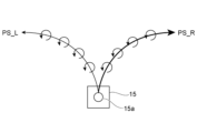
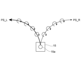
- FIG. 9 is an explanatory diagram showing the case where the reinforcing fibers are Z-twisted and the movement direction of the head unit is a clockwise modeling pass and a counterclockwise modeling pass.
- FIG. 10 is an explanatory diagram showing the case where the reinforcing fibers are S-twisted and the movement direction of the head unit is a clockwise modeling pass and a counterclockwise modeling pass.
- ⁇ Configuration of additive manufacturing device> 1 is a schematic diagram of an FDM-type additive manufacturing apparatus 100.
- the additive manufacturing apparatus 100 includes a filament feeder 13 that feeds a continuous fiber-reinforced resin filament 11 (hereinafter also referred to as a filament), a head unit 15, a table 17, a molding drive unit 19, and a control unit 21.
- the filament feed unit 13 includes a pair of drive rollers 13a that sandwich the filament 11, and a drive unit (not shown) such as a motor that rotates and drives at least one of the drive rollers 13a.
- the head unit 15 includes a heating unit (not shown) that thermally melts the fed filament 11, and a nozzle 15a that ejects the molding material melted by the heating unit.
- the head unit 15 may also be provided with a cutting unit such as a cutter or laser cutting device that cuts the reinforcing fibers contained in the filament 11.
- the table 17 is disposed opposite the nozzle 15a of the head unit 15 and has a modeling surface 17a on which the model is stacked.
- the molding drive unit 19 moves the head unit 15 and the table 17 relative to each other to form the modeling material discharged from the nozzle 15a of the head unit 15 along a desired path.
- the table 17 driven by the molding drive unit 19 may be configured to include, for example, a two-axis drive mechanism that moves the head unit 15 within the plane of the modeling surface 17a of the table 17, and a lifting mechanism that drives the table 17 up and down to adjust the stacking height.
- the table 17 and the molding drive unit 19 function as a drive mechanism that moves the nozzle 15a of the head unit 15 relative to the modeling surface 17a.
- the drive mechanism may be a mechanism that moves the head unit 15 with the table 17 as a fixed side, or a mechanism that operates both the table 17 and the head unit 15.
- the control unit 21 has a function to control the feeding of the filament 11 by the filament feeding unit 13 and the relative movement of the head unit 15 by the drive mechanism, as well as a function to control each of the other units.
- a modeling program that controls each unit including the filament feeding unit 13 and the molding drive unit 19 is input to the control unit 21, and the input modeling program is executed by the control unit 21 to layer-by-layer manufacture an object of a desired shape.
- the control unit 21 is configured by hardware using an information processing device such as a PC (Personal Computer). Each function of the control unit 21 is realized when a control device such as a processor such as a CPU (Central Processing Unit) or MPU (Micro Processor Unit), or a dedicated circuit reads out and executes a program having a specific function stored in a storage device (not shown). Examples of storage devices include memories such as RAM (Random Access Memory), which is a volatile storage area, ROM (Read Only Memory), which is a non-volatile storage area, and storage such as HDD (Hard Disk Drive) and SSD (Solid State Drive). In addition to the above forms, the control unit 21 may be another computer that is remotely connected to the additive manufacturing device 100 via a network or the like.
- a control device such as a processor such as a CPU (Central Processing Unit) or MPU (Micro Processor Unit), or a dedicated circuit reads out and executes a program having a specific function stored in a storage device (not shown). Examples of storage
- the control unit 21 outputs a drive signal to the filament feeder 13, which causes the filament feeder 13 to rotate the drive roller 13a and feed the filament 11 to the head unit 15 at a specified feed speed.
- the head unit 15 heats and thermally melts the fed filament 11.
- the control unit 21 then outputs a drive signal to the molding drive unit 19, which ejects the modeling material melted by the head unit 15 from the nozzle 15a while moving the head unit 15 and the table 17 relative to each other.
- the nozzle 15a of the head unit 15 is driven to move relative to the table 17 along a modeling path created according to the shape of the object.
- new modeling material is ejected from the nozzle 15a along the modeling path and layered on the modeling surface 17a of the table 17 or on the modeling material of the previous layer (existing layer).
- the modeling program contains information on the modeling path described above, as well as information on various modeling conditions required for modeling, such as the feed speed of the filament 11.
- the control unit 21 reads the information on these modeling conditions from the modeling program described above, and layers the modeling material in a specified procedure to form the object.
- Fig. 2A is a schematic cross-sectional view in a radial direction perpendicular to the axial direction of the filament 11.
- Fig. 2B is a side view along the axial direction of the filament 11.
- the same members or parts are denoted by the same reference numerals to simplify or omit the description thereof.
- the filament 11 is a linear resin material used as a modeling material for a 3D printer such as the additive manufacturing device 100 described above.
- a thermoplastic matrix resin 25 is impregnated into a fiber bundle 23 containing continuous fibers (hereinafter also referred to as "reinforcing fibers").
- a matrix resin 27 is formed with a predetermined thickness on the radial outside of the fiber bundle 23 so as to cover the fiber bundle 23.
- These matrix resins 25, 27 (hereinafter also referred to as “resin”) serve as the base material of the filament 11.
- the matrix resins 25, 27 may be thermoplastic resins, other resin materials such as thermosetting resins and photocurable resins, or materials obtained by kneading multiple types of materials.
- the fiber bundles 23 in the filament 11 are arranged along the filament central axis O and are twisted around the filament central axis O.
- the diameter of the filament 11 is preferably, for example, 0.5 mm or more and 1 mm or less, and the smaller the diameter, the more accurately the finer the shape of the molded object can be reproduced. Also, it is preferable that the fiber bundle 23 contains 1,500 or more and 6,000 or less continuous fibers. In this case, the continuous fibers are arranged at a high density in the molded object, and the strength of the molded object can be sufficiently improved.
- the above numerical ranges are merely examples and are not restrictive.
- the number of twists of the continuous fibers of the fiber bundle 23 is 20 times/m or more and 100 times/m or less along the axial direction of the filament 11, the effect of increasing stable fiber opening and improving the molding accuracy is achieved when molding in the molding direction described in detail below.
- the number of twists is more preferably 25 times/m or more, and even more preferably 30 times/m or more.
- the number of twists is more preferably 80 times/m or less, and even more preferably 70 times/m or less.
- the reinforcing fibers that make up the fiber bundle 23 can be organic fibers such as polyethylene fibers, aramid fibers, and Zylon fibers, or inorganic fibers such as boron fibers, glass fibers, carbon fibers, metal fibers, and rock fibers. Surface-treated fibers can be used as the reinforcing fibers to improve the adhesive strength between the resin and the fibers.
- the fiber bundle 23 may be formed of a single bundle as shown in FIG. 2A, but may also be an assembly of multiple fiber bundles, in which case the reinforcing fibers of each fiber bundle may be twisted together or each fiber bundle may be twisted individually.
- examples of the material for the matrix resins 25, 27 include polyolefin resins such as polypropylene or polyethylene, acrylonitrile butadiene styrene resin, polystyrene resin, polyester resins such as polyethylene terephthalate, polybutylene terephthalate, or polylactic acid, polyamide resins, aromatic polyamide resins, polyetherimide, polyarylimide, polyarylate, polyether ether ketone, polyaryl ether ketone, polybenzimidazole, polyethersulfone, polysulfone, polyvinylidene fluoride resin, liquid crystal polymer, polycarbonate resin, polyacetal, or polyphenylene sulfide.
- polyolefin resins such as polypropylene or polyethylene, acrylonitrile butadiene styrene resin, polystyrene resin, polyester resins such as polyethylene terephthalate, polybutylene terephthalate, or polylactic acid, polyamide
- thermoplastic resins may be used alone, or may be blends of multiple resins to improve the heat resistance, heat distortion temperature, heat aging, tensile properties, bending properties, creep properties, compression properties, fatigue properties, impact properties, and sliding properties of the thermoplastic resin.
- thermoplastic resins include polyether ether ketone resin (PEEK)/polytetrafluoroethylene (PTFE), PEEK/polybenzimidazole (PBI), etc.
- Thermoplastic resins may also be resins to which short fibers such as carbon fiber and glass fiber, talc, etc. have been added.
- antioxidants such as phenols, thioethers, and phosphites
- ultraviolet absorbers such as benzotriazoles or triazines
- metal deactivators such as hydrazides or amides
- thermoplastic resins improves their flexibility, improving the molding accuracy during molding and the flexibility of the molded object.
- thermoplastic resins can improve the flame retardancy of the molded object.
- thermoplastic resins can control thermal expansion during molding, improving molding accuracy.
- thermoplastic resins can improve the antistatic properties of the molded object.
- the filament By adding lubricants such as hydrocarbon-based or metal soap-based lubricants to thermoplastic resins and improving the lubricity of the continuous fiber reinforced filament, the filament can be smoothly fed out during molding.
- lubricants such as hydrocarbon-based or metal soap-based lubricants
- the filament 11 used in the above-mentioned 3D printer is formed by twisting the reinforcing fibers of the fiber bundle 23, so that the orientation angle of the reinforcing fibers is inclined with respect to the axial direction.
- An example of a method for producing such a filament 11 will be described. Note that the configuration of the filament production device shown here is one example, and is not limited to this.
- FIG. 3 is a schematic diagram of the filament manufacturing apparatus 200.
- the filament manufacturing apparatus 200 includes a fiber material supply section 31 , a kneading extruder 33 , a resin bath section 35 , a cooling section 37 , and a twisting section 39 .
- the fiber material supply section 31 delivers one or more fiber bundles 23 wound in a coil shape at a predetermined speed.
- the kneading extruder 33 is provided with a screw shaft (not shown) having kneading blades rotatably in a hollow chamber 33a, and melts and plasticizes the resin fed from a hopper 33b.
- the resin bath section 35 impregnates the fiber bundle 23 delivered from the fiber material supply section 31 with the resin plasticized by the kneading extruder 33.
- the cooling section 37 is disposed downstream of the resin bath section 35, and cools the composite 41 delivered from the resin bath section 35.
- the twisting section 39 mainly twists the fiber bundle 23 before cooling around the axial center.
- the resin bath section 35 is formed into a cylindrical shape with the cylinder axis oriented vertically. Resin 43 plasticized by the kneading extruder 33 is supplied and stored inside the cylinder. The upper end of the resin bath section 35 is open, and the fiber bundle 23 guided by the guide rollers 45 is pulled into the resin 43 stored in the resin bath section 35 from the opening at the upper end.
- the fiber bundle 23 introduced from the opening at the upper end of the resin bath section 35 is passed around each impregnation roll in turn and sent to the outlet section 47 located at the lower end of the resin bath section 35.
- the outlet section 47 is provided with a die 49 that shapes the outer periphery of the filament 11 when the composite 41 of the resin 43 and the fiber bundle 23 is drawn out of the resin bath section 35. Depending on the opening shape of the die 49, it is possible to form irregularities such as grooves and ridges on the outer periphery of the filament 11.
- the cooling section 37 is a long water tank arranged along the direction in which the composite 41 is pulled out of the resin bath section 35, and cooling water 51 is stored in the tank. In this cooling section 37, the resin impregnated in the fiber bundles 23 of the composite 41 is cooled in the cooling water 51 and hardened.
- the twisting section 39 is disposed downstream of the cooling section 37 and has a pair of upper and lower take-up rolls 53, 55 that are in contact with each other's outer circumferential surfaces.
- the twisting section 39 can employ various mechanisms. For example, although not shown, it may be a mechanism that rotates a bobbin that winds the filament 11 around the axis of the filament 11.
- the take-up rolls 53, 55 have the function of drawing the fiber bundle 23 from the fiber material supply section 31 to the resin bath section 35, and further drawing out the composite 41 from the resin bath section 35 to the cooling section 37 and twisting section 39.
- a separate winding section (not shown) such as a bobbin is provided downstream of the twisting section 39 to wind up the manufactured filament 11.
- the procedure for producing the filament 11 using the above-described filament production apparatus 200 is as follows.
- the impregnation process is carried out in the resin bath section 35 of the filament manufacturing device 200. Specifically, the resin supplied from the hopper 33b is kneaded in the kneading extruder 33, and the molten resin is stored in the resin bath section 35.
- the fiber bundle 23 is supplied from the fiber material supply section 31 to this resin bath section 35.
- the fiber bundle 23 impregnated with the molten resin in the resin bath section 35 is passed through a die 49 disposed in the outlet section 47 to adjust the amount of resin impregnation.
- This resin impregnation results in a state in which the matrix resin is present in the gaps in the fiber bundle 23 and around the radial outer periphery of the fiber bundle 23.
- the composite 41 of the matrix resin and the fiber bundle 23 obtained in this manner is cooled in the cooling section 37.
- twisting process In the twisting process, the twisting unit 39 twists the fiber bundle 23 impregnated with the resin in the resin bath unit 35. Specifically, while rotating the take-up rolls 53, 55 of the twisting unit 39, the composite 41 that has passed through the cooling unit 37 is passed between the take-up rolls 53, 55. This imparts a twist to the continuous fibers of the fiber bundle 23.
- the number of twists and the twist angle can be adjusted by adjusting the inclination angle of the take-up rolls 53, 55 with respect to the take-up direction.
- the matrix resin 25 containing a thermoplastic resin is impregnated into the fiber bundles 23 arranged along the central axis O of the filament, thereby obtaining a filament 11 in which the matrix resin 27 is formed on the radially outer periphery of the fiber bundles 23 so as to cover the fiber bundles 23.
- each of the fiber bundles supplied from the multiple fiber material supply units 31 may be twisted individually, or each fiber bundle may be twisted collectively.
- FIGS. 4A and 4B are schematic diagrams showing how a molding material formed by melting a filament 11 is discharged onto a printing surface from a nozzle (not shown), with Fig. 4A being an explanatory diagram showing a vertical cross section of the filament 11, and Fig. 4B being a schematic plan view showing a partial cross section when Fig. 4A is viewed in plan.
- the filament 11 is fed and supplied in the vertical direction, and the melted molding material is discharged onto the printing surface 17a along the printing direction WD.
- the fiber bundles 23 in the molding material are spread to a width W wider than the width W0 of the filament 11 before it is melted.
- the fibers may not be fully opened even after the molding material is discharged.
- the fusion between the molding material and the molding surface 17a or base of the table 17 shown in Figure 1 may be incomplete, or the reinforcing fibers may be unevenly dispersed during molding, affecting the strength of the molded object. Therefore, during molding, it is preferable to discharge the molding material while untwisting the fiber bundle 23.
- the open state of the fiber bundle 23 changes depending on the number of twists of the reinforcing fibers in the original fiber bundle 23 and the direction of the molding pass (molding direction).
- Z twist and S twist are commonly known as twist directions.
- Fig. 5 is an explanatory diagram showing a typical twist direction when the reinforcing fibers of the fiber bundle 23 in the filament 11 are Z-twisted.
- Fig. 6 is an explanatory diagram showing a typical twist direction when the reinforcing fibers of the fiber bundle 23 in the filament 11 are S-twisted.
- Figs. 5 and 6 show three long fibers twisted in a spiral shape along the central axis O of the filament, together with layers L1 to L6 of each cross section along the longitudinal direction of the filament 11 (fiber bundle 23).
- the vertical downward direction is considered to be the discharge side from the nozzle 15a (FIG. 1) which is the front of the filament feed direction FD.
- the reinforcing fiber passing the position of the nozzle 15a rotates counterclockwise.
- the layers L 1 to L 6 of the filament 11 are sequentially arranged at the discharge position from the nozzle 15a.
- the position of the fiber F moves counterclockwise from the position of the fiber F in the layer L 1 when the layer L 2 reaches the position of the nozzle 15a as the filament 11 is fed.
- the feeding of the filament 11 proceeds to the layers L 3 to L 6 , the arrangement of the fiber F in each layer rotates counterclockwise around the central axis O of the filament.
- Figure 7 is an explanatory diagram showing the direction in which the Z-twisted reinforcing fibers of the fiber bundle 23 in the shaping material rotate in position as the filament 11 is fed at the same nozzle position.
- Figure 8 is an explanatory diagram showing the direction in which the S-twisted reinforcing fibers of the fiber bundle 23 in the shaping material rotate in position as the filament 11 is fed at the same nozzle position.
- the twisted reinforcing fibers of the fiber bundle 23 are continuously supplied at the nozzle 15a while rotating counterclockwise as the filament 11 is fed. Also, when the reinforcing fibers of the fiber bundle 23 are S-twisted as shown in FIG. 8, the twisted reinforcing fibers of the fiber bundle 23 are continuously supplied at the nozzle 15a while rotating clockwise as the filament 11 is fed.
- the shaping direction of the shaping pass PS_R is curved in the opposite direction to the twist direction (counterclockwise) of the reinforcing fibers, so the reinforcing fibers are easily untwisted. Therefore, in the case of Z-twist, if the shaping direction is set to the direction of the shaping pass PS_R, it is easy to obtain a good open state as shown in FIG. 4B.
- the control unit 21 sets a modeling path with a preferred modeling direction according to the determination result. Specifically, a modeling path for Z-twist and a modeling path for S-twist may be prepared in the modeling program, and the control unit 21 may selectively use one of the modeling paths to perform modeling.
- test example A1 the twist angle ⁇ was 3° and the number of twists N was 33 turns/m
- test example A2 the twist angle ⁇ was 7° and the number of twists N was 78 turns/m
- test example B1 the twist angle ⁇ was 10° and the number of twists N was 112 turns/m. In this way, the filaments of test examples A1, A2, and B1 were formed.
- test examples A5, A6 and B3 the same thermoplastic resin and filament manufacturing device 200 as in test examples A1, A2 and B1 were used, and a single fiber bundle consisting of 6,000 Pyrofil (registered trademark) TR50S 6L (manufactured by Mitsubishi Chemical Corporation) fibers was used as the reinforcing fiber. In this way, a fiber-reinforced resin filament (cross-sectional diameter 1 mm) with a fiber content of 40% by mass was produced.
- twist angle ⁇ and twist number N of the composite 41 were set in the same manner as above.
- the twist angle ⁇ was 6° and the twist number N per meter was 33 turns/m
- the twist angle ⁇ was 10° and the twist number N per meter was 56 turns/m
- the twist angle ⁇ was 20° and the twist number N was 116 turns/m.
- the filaments of test examples A5, A6, and B3 were formed.
- the obtained various filaments were used as filaments for a 3D printer as shown in FIG. 1, and a one-layer molded object was obtained under the conditions of a nozzle temperature of 260°C, a table temperature of 60°C, and a printing speed of 5 mm/sec. This molding was performed based on a circular curved molding model (molding path) with a radius of 5 mm. The spread width of the reinforcing fibers was measured from the captured image of a circular molded object molded on the molding surface, which was imaged with a laser microscope.
- the radius of curvature of the curved modeling path is smaller than, for example, 2.5 mm, which is half the filament diameter, the radius of curvature of the modeling path becomes too close to the spread width, causing the model to fold over on the inner side of the model, reducing the reproducibility of the shape of the set curved model. Therefore, this evaluation is limited to cases where the radius of curvature of the curved modeling path (bending) is larger than the radius of the filament.
- the maximum possible spread width corresponds to the total width of the modeling material on the modeling surface when the modeling material, which is the thermally melted matrix resins 25, 27 contained in the filament 11, is ejected from the nozzle 15a and spreads out on the modeling surface in a direction perpendicular to the modeling direction.
- a layered manufacturing method in which a modeling material obtained by heating and melting a linear continuous fiber reinforced filament is discharged from a nozzle along a modeling path on a modeling surface to model a curved or bent shape on the modeling surface,
- the continuous fiber reinforced filament includes a substrate including a thermoplastic resin and at least one fiber bundle including continuous fibers impregnated in the substrate and extending in an axial direction;
- the continuous fibers of the fiber bundle are twisted about an axial core of the continuous fiber reinforced filament at 20 turns/m or more and 100 turns/m or less,
- the shaping path on the shaping surface is a path for discharging the shaping material while curving or bending it to the right side toward the front of the shaping direction
- the shaping path is a path for discharging the shaping material while curving or bending it to the left side toward the front of the shaping direction, thereby forming the curved or bent shape.
- Additive manufacturing methods when a continuous fiber reinforced filament having a fiber bundle is molded using a molten molding material, the filament is molded in the opposite direction to the twist direction of the continuous fibers of the fiber bundle, thereby improving the spreadability without reducing the molding accuracy.
- the twist number of the continuous fibers is 20 times/m or more and 100 times/m or less, the effect is remarkable.
- the adhesion between adjacent molding materials can be improved, and a decrease in the strength of the molded object can be suppressed.
- An additive manufacturing device including: a head unit that discharges a modeling material obtained by heating and melting a linear continuous fiber reinforced filament from a nozzle; a drive mechanism that moves the nozzle of the head unit relatively to a modeling surface; and a control unit that drives the drive mechanism to discharge the modeling material along a set modeling path
- the continuous fiber reinforced filament includes a substrate including a thermoplastic resin and at least one fiber bundle including continuous fibers impregnated in the substrate and extending in an axial direction;
- the continuous fibers of the fiber bundle are twisted about an axial core of the continuous fiber reinforced filament at 20 turns/m or more and 100 turns/m or less
- the control unit of the additive manufacturing device when forming a curved or bent shape on the manufacturing surface, sets the manufacturing path on the manufacturing surface to a path that ejects the manufacturing material while curving or bending the fiber bundle to the right toward the front in the manufacturing direction when the fiber bundle is Z-twisted, and sets the manufacturing path to a path that ejects the manufacturing material while curving or bending the
- this additive manufacturing device when a continuous fiber reinforced filament having a fiber bundle is molded using a molten molding material, the filament is molded in the opposite direction to the twist direction of the continuous fibers of the fiber bundle, thereby improving the spreadability without reducing the molding accuracy.
- the twist number of the continuous fibers is 20 turns/m or more and 100 turns/m or less, the effect is remarkable.
- the adhesion between adjacent molding materials can be improved, and a decrease in the strength of the molded object can be suppressed.
- a program for executing an additive manufacturing procedure in which a modeling material obtained by heating and melting a linear continuous fiber reinforced filament is ejected from a nozzle along a modeling path on a modeling surface to model a curved or bent shape on the modeling surface,
- the continuous fiber reinforced filament includes a substrate including a thermoplastic resin and at least one fiber bundle including continuous fibers impregnated in the substrate and extending in an axial direction;
- the continuous fibers of the fiber bundle are twisted about an axial core of the continuous fiber reinforced filament at 20 turns/m or more and 100 turns/m or less
- a program that executes a procedure for forming the curved or bent shape by setting the modeling path on the modeling surface to a path that ejects the modeling material while curving or bending the fiber bundle to the right toward the front in the modeling direction when the fiber bundle is Z-twisted, and setting the modeling path on the modeling surface to a path that ejects the modeling material while curving or bending the fiber bundle to the left toward the front in the modeling direction when the fiber bundle
- the filament is molded in the opposite direction to the twist direction of the continuous fibers of the fiber bundle, thereby improving the spreadability without reducing the molding accuracy.
- the number of twists of the continuous fibers is 20 times/m or more and 100 times/m or less, the effect is remarkable.
- the adhesion between adjacent molding materials can be improved, and a decrease in the strength of the molded object can be suppressed.
- Filament continuous fiber reinforced resin filament
- Filament feeding section 13a Drive roller 15 Head section 15a Nozzle 17 Table 17a Modeling surface 19 Forming drive section 21 Control section 23 Fiber bundle 25 Matrix resin 27 Matrix resin 31 Fiber material supply section 33 Kneading extruder 33a Chamber 33b Hopper 35 Resin bath section 37 Cooling section 39 Twisting section 41 Composite 43 Resin 45 Guide roller 47 Outlet section 49 Die 51 Cooling water 53, 55 Take-up roll 100 Layered modeling device 200 Filament manufacturing device
Landscapes
- Engineering & Computer Science (AREA)
- Chemical & Material Sciences (AREA)
- Materials Engineering (AREA)
- Manufacturing & Machinery (AREA)
- Mechanical Engineering (AREA)
- Composite Materials (AREA)
- Physics & Mathematics (AREA)
- Optics & Photonics (AREA)
- Robotics (AREA)
- Civil Engineering (AREA)
- Structural Engineering (AREA)
- Ceramic Engineering (AREA)
- Moulding By Coating Moulds (AREA)
- Yarns And Mechanical Finishing Of Yarns Or Ropes (AREA)
Abstract
Description
(1) 線状の連続繊維強化フィラメントを加熱溶融した造形材を、造形面上で造形パスに沿ってノズルから吐出させて、前記造形面上に湾曲形状又は屈曲形状を造形する積層造形方法であって、
前記連続繊維強化フィラメントは、熱可塑性樹脂を含む基材と、前記基材中に含浸されて軸方向に延在する連続繊維を含む少なくとも1つの繊維束とを備え、
前記繊維束の前記連続繊維には、前記連続繊維強化フィラメントの軸芯を中心に20回/m以上、100回/m以下の撚りが付与されており、
前記造形面における前記造形パスを、前記繊維束がZ撚りの場合には、造形方向前方に向けて右側へ湾曲又は屈曲させながら前記造形材を吐出させるパスにし、前記繊維束がS撚りの場合には、造形方向前方向けて左側へ湾曲又は屈曲させながら前記造形材を吐出させるパスにして前記湾曲形状又は前記屈曲形状を造形する、
積層造形方法。
(2) 線状の連続繊維強化フィラメントを加熱溶融した造形材をノズルから吐出するヘッド部と、前記ヘッド部の前記ノズルを造形面に対して相対移動させる駆動機構と、設定された造形パスに沿って前記造形材を吐出させるように前記駆動機構を駆動する制御部と、を備える積層造形装置であって、
前記連続繊維強化フィラメントは、熱可塑性樹脂を含む基材と、前記基材中に含浸されて軸方向に延在する連続繊維を含む少なくとも1つの繊維束とを備え、
前記繊維束の前記連続繊維には、前記連続繊維強化フィラメントの軸芯を中心に20回/m以上、100回/m以下の撚りが付与されており、
前記制御部は、前記造形面上に湾曲形状又は屈曲形状を造形する際、前記造形面における前記造形パスを、前記繊維束がZ撚りの場合には、造形方向前方に向けて右側へ湾曲又は屈曲させながら前記造形材を吐出させるパスにし、前記繊維束がS撚りの場合には、造形方向前方向けて左側へ湾曲又は屈曲させながら前記造形材を吐出させるパスにして、前記湾曲形状又は前記屈曲形状を造形させる、
積層造形装置。
(3) 線状の連続繊維強化フィラメントを加熱溶融した造形材を、造形面上で造形パスに沿ってノズルから吐出させて、前記造形面上に湾曲形状又は屈曲形状を造形する積層造形手順を実行するプログラムであって、
前記連続繊維強化フィラメントは、熱可塑性樹脂を含む基材と、前記基材中に含浸されて軸方向に延在する連続繊維を含む少なくとも1つの繊維束とを備え、
前記繊維束の前記連続繊維には、前記連続繊維強化フィラメントの軸芯を中心に20回/m以上、100回/m以下の撚りが付与されており、
コンピュータに、
前記造形面における前記造形パスを、前記繊維束がZ撚りの場合には、造形方向前方に向けて右側へ湾曲又は屈曲させながら前記造形材を吐出させるパスにし、前記繊維束がS撚りの場合には、造形方向前方向けて左側へ湾曲又は屈曲させながら前記造形材を吐出させるパスにして前記湾曲形状又は前記屈曲形状を造形する手順を実行させる、
プログラム。
図1は、FDM方式の積層造形装置100の概略構成図である。積層造形装置100は、連続繊維強化樹脂フィラメント11(以下、フィラメントともいう。)を送給するフィラメント送給部13と、ヘッド部15と、テーブル17と、成形駆動部19と、制御部21とを備える。
本構成の積層造形装置100においては、制御部21がフィラメント送給部13に駆動信号を出力することにより、フィラメント送給部13が駆動ローラ13aを回転駆動して、フィラメント11を指定された送給速度でヘッド部15に送給する。ヘッド部15は、送給されたフィラメント11を加熱して熱溶解させる。そして、制御部21は、成形駆動部19に駆動信号を出力し、ヘッド部15で溶解した造形材を、ヘッド部15とテーブル17とを相対移動させながらノズル15aから吐出させる。
次に、上記した積層造形装置100で用いるフィラメント11の構成を説明する。
図2Aは、フィラメント11の軸方向に直交する径方向の概略断面図である。図2Bは、フィラメント11の軸方向に沿った側面図である。以下の説明では、同一の部材又は部位に対しては同一の符号を付与することで、その説明を簡単化又は省略する。
上記した3Dプリンタに用いられるフィラメント11は、繊維束23の強化用繊維に撚りが付与されて、強化用繊維の配向角が軸方向に対して傾斜している。このようなフィラメント11の製法例について説明する。なお、ここで示すフィラメント製造装置の構成は一例であって、これに限らない。
フィラメント製造装置200は、繊維材料供給部31と、混練押出機33と、樹脂浴部35と、冷却部37と、撚り部39とを備える。
繊維材料供給部31は、コイル状に巻かれた1つ又は複数の繊維束23を所定の速度で送り出す。混練押出機33は、内部が空洞とされたチャンバ33a内に混練翼を有するスクリュシャフト(不図示)を回転自在に備えており、ホッパ33bから投入された樹脂を融解して可塑化する。樹脂浴部35は、繊維材料供給部31から送り出された繊維束23に、混練押出機33で可塑化された樹脂を含浸させる。冷却部37は、樹脂浴部35の下流側に配設され、樹脂浴部35から送り出される複合体41を冷却する。撚り部39は、主として冷却前の繊維束23に軸中心周りの撚りを付与させる。
(含浸工程)
含浸工程は、フィラメント製造装置200の樹脂浴部35により実施する。具体的には、ホッパ33bから供給された樹脂を混練押出機33で混練し、融解状態の樹脂を樹脂浴部35に貯留する。この樹脂浴部35に繊維材料供給部31から繊維束23を供給する。そして、樹脂浴部35内で融解状態の樹脂を含浸させた繊維束23に、出口部47に配置されたダイス49を通過させることで、樹脂の含浸量を調整する。この樹脂の含浸により、繊維束23内の隙間、繊維束23の径方向外側の周囲にマトリクス樹脂が存在した状態となる。このようにして得られたマトリクス樹脂と繊維束23との複合体41を冷却部37で冷却する。
撚り工程では、撚り部39によって、樹脂浴部35内で樹脂が含浸された状態の繊維束23に撚りを付与する。具体的には、撚り部39の引き取りロール53,55を回転させながら、冷却部37を通過した複合体41を引き取りロール53,55同士の間に通過させる。これにより、繊維束23の連続繊維に撚りが付与される。上記の引き取りロール53,55の引き取り方向に対する傾斜角度を調整することで、撚り回数及び撚り角度を調整できる。
上記したフィラメント11を用いて熱溶解積層方式により造形物を造形する際、繊維束23の強化用繊維に付与された撚り数が大きい場合には、ノズル15aから吐出される繊維束23の開繊幅が、造形パスの形状によっては低下又は不安定化しやすくなる。
図9は、強化用繊維がZ撚りの場合に、ヘッド部15の移動方向が、時計回り(右側へ湾曲)の造形パスPS_Rの場合と、反時計回り(左側へ湾曲)の造形パスPS_Lの場合を示す説明図である。Z撚りの場合では、造形パスPS_Lの造形方向では、強化用繊維の撚りの方向(反時計回り)と同じ方向に湾曲するため、強化用繊維の撚りが解消されにくく、従って開繊しにくくなる。一方、造形パスPS_Rの造形方向では、強化用繊維の撚りの方向(反時計回り)と逆の方向に湾曲するため、強化用繊維の撚りが解消されやすくなる。そのため、Z撚りの場合には、造形方向を造形パスPS_Rの方向にすると、図4Bに示す良好な開繊状態が得やすくなる。

試験例A3では、撚り角θが3°、撚り数Nが24回/m、試験例A4では、撚り角θが7°、撚り数Nが56回/m、試験例B2では、撚り角θが13°、撚り数Nが105回/mの撚りを付与した。こうして、試験例A3、A4及び試験例B2のフィラメントを形成した。
得られた各種のフィラメントを図1に示すような3Dプリンタ用のフィラメントとして使用し、ノズル温度260℃、テーブル温度60℃、印刷速度5mm/secの条件で1層からなる造形物を得た。この造形には、半径が5mmの円形状の曲線造形モデル(造形パス)に基づき実施した。強化用繊維の開繊幅については、造形面上に造形した円形状の造形物をレーザー顕微鏡により撮像し、その撮像画像から計測した。具体的には、画像処理ソフトウェアを用いて造形物の円周方向に沿った複数箇所で、造形物内の強化用繊維の径方向幅を計測し、その平均値を開繊幅とした。そして、時計回り又は反時計回りに湾曲した造形パスに沿った造形方向(印刷方向)ごとに開繊幅を比較し、造形方向を強化用繊維の撚りの解消方向に設定したことによる開繊幅の増大効果が認められた場合には、方向優位性を「有」と示し、増大効果が認められない場合には、方向優位性を「無」とした。
上記の開繊性を評価した造形物について、前述したレーザー顕微鏡及び画像処理ソフトウェアを用い、円形状の外周及び内周の真円度をそれぞれ算出し、内周と外周との平均値を求めた。求めた真円度の平均値を、造形方向(印刷方向)が時計回りに湾曲した場合と反時計回りに湾曲した場合とで比較して、設定した円軌道(円形の造形パス)からのずれの大小より造形精度を評価した。造形方向を強化用繊維の撚りの解消方向に設定したことによる造形精度の向上効果が認められた場合には、方向優位性を「有」と示し、造形精度の向上効果が認められない場合には、方向優位性を「無」と示した。
その結果、試験例A1~A5及び試験例B1~B3においては、開繊幅に関して、撚りの解消方向に湾曲する造形方向での測定結果が、撚り方向に湾曲する造形方向での測定結果より大きくなった。真円度に関しては、試験例A1~A5において、撚りの解消方向に湾曲する造形方向での測定結果が、撚り方向に湾曲する造形方向での測定結果より大きくなった。一方、試験例B1~B3においては、撚りの解消方向に湾曲する造形方向での測定結果が、撚り方向に湾曲する造形方向での測定結果より小さくなった。
(1) 線状の連続繊維強化フィラメントを加熱溶融した造形材を、造形面上で造形パスに沿ってノズルから吐出させて、前記造形面上に湾曲形状又は屈曲形状を造形する積層造形方法であって、
前記連続繊維強化フィラメントは、熱可塑性樹脂を含む基材と、前記基材中に含浸されて軸方向に延在する連続繊維を含む少なくとも1つの繊維束とを備え、
前記繊維束の前記連続繊維には、前記連続繊維強化フィラメントの軸芯を中心に20回/m以上、100回/m以下の撚りが付与されており、
前記造形面における前記造形パスを、前記繊維束がZ撚りの場合には、造形方向前方に向けて右側へ湾曲又は屈曲させながら前記造形材を吐出させるパスにし、前記繊維束がS撚りの場合には、造形方向前方向けて左側へ湾曲又は屈曲させながら前記造形材を吐出させるパスにして前記湾曲形状又は前記屈曲形状を造形する、
積層造形方法。
この積層造形方法によれば、繊維束を有する連続繊維強化フィラメントを溶解した造形材により造形する際に、繊維束の連続繊維の撚り方向と反対方向に造形することで、造形精度を低下させずに開繊性を向上できる。特に、連続繊維の撚り数が20回/m以上、100回/m以下であると、その効果が顕著となる。その結果、隣接する造形材同士の密着性を向上でき、造形物の強度低下を抑制できる。
この積層造形方法によれば、ノズルから吐出された造形材が重なり合うことがなく、高い造形精度を維持できる。
この積層造形方法によれば、連続繊維が造形物中に高い密度で配置されるため、造形物の強度を十分に向上できる。
この積層造形方法によれば、造形物の細かな形状を正確に再現できる。
前記連続繊維強化フィラメントは、熱可塑性樹脂を含む基材と、前記基材中に含浸されて軸方向に延在する連続繊維を含む少なくとも1つの繊維束とを備え、
前記繊維束の前記連続繊維には、前記連続繊維強化フィラメントの軸芯を中心に20回/m以上、100回/m以下の撚りが付与されており、
前記制御部は、前記造形面上に湾曲形状又は屈曲形状を造形する際、前記造形面における前記造形パスを、前記繊維束がZ撚りの場合には、造形方向前方に向けて右側へ湾曲又は屈曲させながら前記造形材を吐出させるパスにし、前記繊維束がS撚りの場合には、造形方向前方向けて左側へ湾曲又は屈曲させながら前記造形材を吐出させるパスにして、前記湾曲形状又は前記屈曲形状を造形させる、積層造形装置。
この積層造形装置によれば、繊維束を有する連続繊維強化フィラメントを溶解した造形材により造形する際に、繊維束の連続繊維の撚り方向と反対方向に造形することで、造形精度を低下させずに開繊性を向上できる。特に、連続繊維の撚り数が20回/m以上、100回/m以下であると、その効果が顕著となる。その結果、隣接する造形材同士の密着性を向上でき、造形物の強度低下を抑制できる。
前記連続繊維強化フィラメントは、熱可塑性樹脂を含む基材と、前記基材中に含浸されて軸方向に延在する連続繊維を含む少なくとも1つの繊維束とを備え、
前記繊維束の前記連続繊維には、前記連続繊維強化フィラメントの軸芯を中心に20回/m以上、100回/m以下の撚りが付与されており、
コンピュータに、
前記造形面における前記造形パスを、前記繊維束がZ撚りの場合には、造形方向前方に向けて右側へ湾曲又は屈曲させながら前記造形材を吐出させるパスにし、前記繊維束がS撚りの場合には、造形方向前方向けて左側へ湾曲又は屈曲させながら前記造形材を吐出させるパスにして前記湾曲形状又は前記屈曲形状を造形する手順を実行させる、プログラム。
このプログラムによれば、繊維束を有する連続繊維強化フィラメントを溶解した造形材により造形する際に、繊維束の連続繊維の撚り方向と反対方向に造形することで、造形精度を低下させずに開繊性を向上できる。特に、連続繊維の撚り数が20回/m以上、100回/m以下であると、その効果が顕著となる。その結果、隣接する造形材同士の密着性を向上でき、造形物の強度低下を抑制できる。
13 フィラメント送給部
13a 駆動ローラ
15 ヘッド部
15a ノズル
17 テーブル
17a 造形面
19 成形駆動部
21 制御部
23 繊維束
25 マトリクス樹脂
27 マトリクス樹脂
31 繊維材料供給部
33 混練押出機
33a チャンバ
33b ホッパ
35 樹脂浴部
37 冷却部
39 撚り部
41 複合体
43 樹脂
45 ガイドローラ
47 出口部
49 ダイス
51 冷却水
53,55 引き取りロール
100 積層造形装置
200 フィラメント製造装置
Claims (6)
- 線状の連続繊維強化フィラメントを加熱溶融した造形材を、造形面上で造形パスに沿ってノズルから吐出させて、前記造形面上に湾曲形状又は屈曲形状を造形する積層造形方法であって、
前記連続繊維強化フィラメントは、熱可塑性樹脂を含む基材と、前記基材中に含浸されて軸方向に延在する連続繊維を含む少なくとも1つの繊維束とを備え、
前記繊維束の前記連続繊維には、前記連続繊維強化フィラメントの軸芯を中心に20回/m以上、100回/m以下の撚りが付与されており、
前記造形面における前記造形パスを、前記繊維束がZ撚りの場合には、造形方向前方に向けて右側へ湾曲又は屈曲させながら前記造形材を吐出させるパスにし、前記繊維束がS撚りの場合には、造形方向前方向けて左側へ湾曲又は屈曲させながら前記造形材を吐出させるパスにして前記湾曲形状又は前記屈曲形状を造形する、
積層造形方法。 - 前記湾曲形状又は前記屈曲形状の曲率半径は、前記造形面上に吐出された前記造形材の造形方向に直交する幅よりも大きい、
請求項1に記載の積層造形方法。 - 前記繊維束は、1500本以上、6000本以下の連続繊維を含む、
請求項1又は2に記載の積層造形方法。 - 前記連続繊維強化フィラメントの直径は、0.5mm以上、1mm以下である、
請求項1又は2に記載の積層造形方法。 - 線状の連続繊維強化フィラメントを加熱溶融した造形材をノズルから吐出するヘッド部と、前記ヘッド部の前記ノズルを造形面に対して相対移動させる駆動機構と、設定された造形パスに沿って前記造形材を吐出させるように前記駆動機構を駆動する制御部と、を備える積層造形装置であって、
前記連続繊維強化フィラメントは、熱可塑性樹脂を含む基材と、前記基材中に含浸されて軸方向に延在する連続繊維を含む少なくとも1つの繊維束とを備え、
前記繊維束の前記連続繊維には、前記連続繊維強化フィラメントの軸芯を中心に20回/m以上、100回/m以下の撚りが付与されており、
前記制御部は、前記造形面上に湾曲形状又は屈曲形状を造形する際、前記造形面における前記造形パスを、前記繊維束がZ撚りの場合には、造形方向前方に向けて右側へ湾曲又は屈曲させながら前記造形材を吐出させるパスにし、前記繊維束がS撚りの場合には、造形方向前方向けて左側へ湾曲又は屈曲させながら前記造形材を吐出させるパスにして、前記湾曲形状又は前記屈曲形状を造形させる、
積層造形装置。 - 線状の連続繊維強化フィラメントを加熱溶融した造形材を、造形面上で造形パスに沿ってノズルから吐出させて、前記造形面上に湾曲形状又は屈曲形状を造形する積層造形手順を実行するプログラムであって、
前記連続繊維強化フィラメントは、熱可塑性樹脂を含む基材と、前記基材中に含浸されて軸方向に延在する連続繊維を含む少なくとも1つの繊維束とを備え、
前記繊維束の前記連続繊維には、前記連続繊維強化フィラメントの軸芯を中心に20回/m以上、100回/m以下の撚りが付与されており、
コンピュータに、
前記造形面における前記造形パスを、前記繊維束がZ撚りの場合には、造形方向前方に向けて右側へ湾曲又は屈曲させながら前記造形材を吐出させるパスにし、前記繊維束がS撚りの場合には、造形方向前方向けて左側へ湾曲又は屈曲させながら前記造形材を吐出させるパスにして前記湾曲形状又は前記屈曲形状を造形する手順を実行させる、
プログラム。
Priority Applications (2)
| Application Number | Priority Date | Filing Date | Title |
|---|---|---|---|
| EP24825601.8A EP4717441A1 (en) | 2023-06-23 | 2024-05-14 | Additive manufacturing method, additive manufacturing equipment, and program |
| CN202480041269.6A CN121368522A (zh) | 2023-06-23 | 2024-05-14 | 层叠造形方法及层叠造形装置以及程序 |
Applications Claiming Priority (2)
| Application Number | Priority Date | Filing Date | Title |
|---|---|---|---|
| JP2023-103557 | 2023-06-23 | ||
| JP2023103557A JP2025003082A (ja) | 2023-06-23 | 2023-06-23 | 積層造形方法及び積層造形装置並びにプログラム |
Publications (1)
| Publication Number | Publication Date |
|---|---|
| WO2024262192A1 true WO2024262192A1 (ja) | 2024-12-26 |
Family
ID=93935553
Family Applications (1)
| Application Number | Title | Priority Date | Filing Date |
|---|---|---|---|
| PCT/JP2024/017768 Ceased WO2024262192A1 (ja) | 2023-06-23 | 2024-05-14 | 積層造形方法及び積層造形装置並びにプログラム |
Country Status (4)
| Country | Link |
|---|---|
| EP (1) | EP4717441A1 (ja) |
| JP (1) | JP2025003082A (ja) |
| CN (1) | CN121368522A (ja) |
| WO (1) | WO2024262192A1 (ja) |
Citations (9)
| Publication number | Priority date | Publication date | Assignee | Title |
|---|---|---|---|---|
| US10046511B1 (en) * | 2017-12-26 | 2018-08-14 | Arevo, Inc. | Alleviating torsional forces on fiber-reinforced thermoplastic filament |
| WO2018151074A1 (ja) * | 2017-02-15 | 2018-08-23 | 学校法人日本大学 | 3次元プリンティング装置 |
| JP2019081292A (ja) * | 2017-10-30 | 2019-05-30 | 株式会社Ihi | 三次元造形物製造装置及び三次元造形物製造方法 |
| WO2020249603A1 (en) * | 2019-06-11 | 2020-12-17 | BigRep GmbH | 3d printhead for strand de-twisting |
| JP2021123026A (ja) | 2020-02-05 | 2021-08-30 | 株式会社神戸製鋼所 | ストランド及び造形物 |
| JP2021142670A (ja) * | 2020-03-10 | 2021-09-24 | 富士フイルムビジネスイノベーション株式会社 | フィラメント製造装置及び造形装置 |
| WO2022118581A1 (ja) * | 2020-12-04 | 2022-06-09 | 三菱瓦斯化学株式会社 | 成形体の製造方法、樹脂含浸装置、及び3dプリンタ |
| US20230143048A1 (en) * | 2021-11-09 | 2023-05-11 | President And Fellows Of Harvard College | Printhead and method of printing multimaterial filaments including oriented, twisted and/or helical features |
| JP2023103557A (ja) | 2022-01-14 | 2023-07-27 | 株式会社日立製作所 | メタネーション反応器、及び、メタン含有ガスを製造する方法 |
-
2023
- 2023-06-23 JP JP2023103557A patent/JP2025003082A/ja active Pending
-
2024
- 2024-05-14 EP EP24825601.8A patent/EP4717441A1/en active Pending
- 2024-05-14 WO PCT/JP2024/017768 patent/WO2024262192A1/ja not_active Ceased
- 2024-05-14 CN CN202480041269.6A patent/CN121368522A/zh active Pending
Patent Citations (9)
| Publication number | Priority date | Publication date | Assignee | Title |
|---|---|---|---|---|
| WO2018151074A1 (ja) * | 2017-02-15 | 2018-08-23 | 学校法人日本大学 | 3次元プリンティング装置 |
| JP2019081292A (ja) * | 2017-10-30 | 2019-05-30 | 株式会社Ihi | 三次元造形物製造装置及び三次元造形物製造方法 |
| US10046511B1 (en) * | 2017-12-26 | 2018-08-14 | Arevo, Inc. | Alleviating torsional forces on fiber-reinforced thermoplastic filament |
| WO2020249603A1 (en) * | 2019-06-11 | 2020-12-17 | BigRep GmbH | 3d printhead for strand de-twisting |
| JP2021123026A (ja) | 2020-02-05 | 2021-08-30 | 株式会社神戸製鋼所 | ストランド及び造形物 |
| JP2021142670A (ja) * | 2020-03-10 | 2021-09-24 | 富士フイルムビジネスイノベーション株式会社 | フィラメント製造装置及び造形装置 |
| WO2022118581A1 (ja) * | 2020-12-04 | 2022-06-09 | 三菱瓦斯化学株式会社 | 成形体の製造方法、樹脂含浸装置、及び3dプリンタ |
| US20230143048A1 (en) * | 2021-11-09 | 2023-05-11 | President And Fellows Of Harvard College | Printhead and method of printing multimaterial filaments including oriented, twisted and/or helical features |
| JP2023103557A (ja) | 2022-01-14 | 2023-07-27 | 株式会社日立製作所 | メタネーション反応器、及び、メタン含有ガスを製造する方法 |
Also Published As
| Publication number | Publication date |
|---|---|
| CN121368522A (zh) | 2026-01-20 |
| EP4717441A1 (en) | 2026-04-01 |
| JP2025003082A (ja) | 2025-01-09 |
Similar Documents
| Publication | Publication Date | Title |
|---|---|---|
| JP7451200B2 (ja) | ストランド | |
| EP3600840B1 (en) | Method and apparatus for additive manufacturing using filament shaping | |
| CN103282565B (zh) | 纤维增强股线和纤维增强股线的制造方法 | |
| US12385167B2 (en) | Strand with a spiral groove | |
| WO2016039081A1 (ja) | 繊維強化熱可塑性樹脂テープの製造方法、および製造装置 | |
| EP3638726B1 (en) | Method of producing a carbon fiber reinforced molding compound | |
| JP2866963B2 (ja) | 編組構造物のイン‐ライン圧密化 | |
| US12553156B2 (en) | Strand production method, strand production apparatus, and fiber reinforced resin strand | |
| JP2011062971A (ja) | 長繊維強化熱可塑性樹脂ペレットの製造方法 | |
| JP7609742B2 (ja) | ストランド及びストランドの製造方法 | |
| JP2025003082A (ja) | 積層造形方法及び積層造形装置並びにプログラム | |
| JP7812741B2 (ja) | フィラメント及び造形物の製造方法 | |
| JP7392397B2 (ja) | 造形装置 | |
| US12558836B2 (en) | Fiber-reinforced resin strand and additive manufacturing method | |
| JP7812743B2 (ja) | 積層造形方法及び積層造形装置並びにプログラム | |
| JP2015175433A (ja) | 繊維強化樹脂製コイルバネ、及び繊維強化樹脂製コイルバネの製造方法 | |
| JP6445822B2 (ja) | 強化繊維束、強化繊維束の開繊装置及び強化繊維束の開繊方法 | |
| CN122003320A (zh) | 三维成型物的成型方法及程序 | |
| JP2020104473A (ja) | 含浸装置、造形装置 |
Legal Events
| Date | Code | Title | Description |
|---|---|---|---|
| 121 | Ep: the epo has been informed by wipo that ep was designated in this application |
Ref document number: 24825601 Country of ref document: EP Kind code of ref document: A1 |
|
| WWE | Wipo information: entry into national phase |
Ref document number: 2024825601 Country of ref document: EP |
|
| NENP | Non-entry into the national phase |
Ref country code: DE |
|
| ENP | Entry into the national phase |
Ref document number: 2024825601 Country of ref document: EP Effective date: 20251222 |
|
| ENP | Entry into the national phase |
Ref document number: 2024825601 Country of ref document: EP Effective date: 20251222 |
|
| ENP | Entry into the national phase |
Ref document number: 2024825601 Country of ref document: EP Effective date: 20251222 |
|
| WWP | Wipo information: published in national office |
Ref document number: 2024825601 Country of ref document: EP |