WO2024262099A1 - 回転装置 - Google Patents
回転装置 Download PDFInfo
- Publication number
- WO2024262099A1 WO2024262099A1 PCT/JP2024/008777 JP2024008777W WO2024262099A1 WO 2024262099 A1 WO2024262099 A1 WO 2024262099A1 JP 2024008777 W JP2024008777 W JP 2024008777W WO 2024262099 A1 WO2024262099 A1 WO 2024262099A1
- Authority
- WO
- WIPO (PCT)
- Prior art keywords
- wall surface
- turbine
- vane
- vane plate
- vanes
- Prior art date
Links
- 230000007423 decrease Effects 0.000 description 4
- 230000000694 effects Effects 0.000 description 3
- 238000001816 cooling Methods 0.000 description 1
- 230000008878 coupling Effects 0.000 description 1
- 238000010168 coupling process Methods 0.000 description 1
- 238000005859 coupling reaction Methods 0.000 description 1
- 238000002474 experimental method Methods 0.000 description 1
- 239000012530 fluid Substances 0.000 description 1
- 239000000463 material Substances 0.000 description 1
- 238000000746 purification Methods 0.000 description 1
- 238000005096 rolling process Methods 0.000 description 1
Images


Classifications
-
- F—MECHANICAL ENGINEERING; LIGHTING; HEATING; WEAPONS; BLASTING
- F02—COMBUSTION ENGINES; HOT-GAS OR COMBUSTION-PRODUCT ENGINE PLANTS
- F02B—INTERNAL-COMBUSTION PISTON ENGINES; COMBUSTION ENGINES IN GENERAL
- F02B37/00—Engines characterised by provision of pumps driven at least for part of the time by exhaust
- F02B37/12—Control of the pumps
- F02B37/24—Control of the pumps by using pumps or turbines with adjustable guide vanes
-
- F—MECHANICAL ENGINEERING; LIGHTING; HEATING; WEAPONS; BLASTING
- F02—COMBUSTION ENGINES; HOT-GAS OR COMBUSTION-PRODUCT ENGINE PLANTS
- F02B—INTERNAL-COMBUSTION PISTON ENGINES; COMBUSTION ENGINES IN GENERAL
- F02B39/00—Component parts, details, or accessories relating to, driven charging or scavenging pumps, not provided for in groups F02B33/00 - F02B37/00
Definitions
- Patent Document 1 discloses a fixed blade arranged radially outward from a turbine impeller.
- the fixed blade is arranged in a passage between a bearing housing and a turbine housing.
- the fixed blade includes a plurality of blade bodies and an annular movable member.
- the plurality of blade bodies are fixed to the front surface of the movable member.
- the ends of the blade bodies face the turbine housing.
- a disc spring is arranged in the space between the back surface of the movable member and the bearing housing. The disc spring presses the blade body against the turbine housing. With this configuration, the clearance between the blade body and the turbine housing is suppressed. Therefore, the decrease in turbine efficiency is suppressed.
- the present disclosure aims to provide a rotating device that can reduce the clearance between the vane and the housing.
- a rotating device includes an impeller, a plurality of vanes arranged circumferentially in a radially outer region of the impeller and protruding in the axial direction, a first wall surface facing each tip of the vanes in the axial direction, and an inclined surface formed on at least one of the first wall surface and the tips of the vanes and inclined relative to the radial direction of the impeller.
- the rotating device may be an annular vane plate disposed radially outward from the impeller and including a first surface facing the axial direction and a second surface opposite the first surface
- the vanes may include a vane plate protruding from the first surface of the vane plate, a second wall surface sandwiching the vane plate and the vanes and facing the first wall surface in the axial direction, the second wall surface facing the second surface of the vane plate, and an elastic body disposed between the second surface of the vane plate and the second wall surface and pushing the vane plate and the vanes toward the first wall surface.
- the inclined surface may be formed on a first wall surface, and the first wall surface may be located radially inward relative to the tips of the vanes and include a discontinuity protruding from the inclined surface.
- FIG. 1 is a schematic cross-sectional view of a turbocharger including a turbine according to a first embodiment.
- FIG. 2 is a schematic enlarged cross-sectional view showing a portion A in FIG.
- FIG. 3 is an enlarged schematic cross-sectional view illustrating the deformation modes of a vane plate of a turbine that does not include an inclined surface when the vane plate is heated.
- FIG. 4 is an enlarged schematic cross-sectional view illustrating the deformation modes of a vane plate of a turbine that does not include an inclined surface as the vane plate is cooled.
- FIG. 5 is an enlarged schematic cross-sectional view showing the behavior of the vanes when the vane plate in FIG. 2 is heated.
- FIG. 1 is a schematic cross-sectional view of a turbocharger including a turbine according to a first embodiment.
- FIG. 2 is a schematic enlarged cross-sectional view showing a portion A in FIG.
- FIG. 3 is an enlarged schematic cross-sectional view illustrating the de
- FIG. 6 is a schematic enlarged cross-sectional view of a turbine according to a second embodiment.
- FIG. 7 is a schematic enlarged cross-sectional view of a turbine according to a third embodiment.
- FIG. 8 is a schematic enlarged cross-sectional view of a turbine according to a fourth embodiment.
- FIG. 9 is a schematic enlarged cross-sectional view of a turbine according to a fifth embodiment.
- FIG. 1 is a schematic cross-sectional view of a turbocharger 100 including a turbine T1 according to a first embodiment.
- the turbine T1 according to this embodiment is applied to the turbocharger 100.
- the turbine T1 may be applied to equipment other than the turbocharger 100, or may be a standalone unit.
- the turbocharger 100 includes a housing 1, a shaft 2, a turbine impeller 3, and a compressor impeller 4.
- the turbine impeller 3 and the compressor impeller 4 rotate integrally with the shaft 2. Therefore, in this disclosure, the axial, radial, and circumferential directions of the shaft 2, the turbine impeller 3, and the compressor impeller 4 may be referred to simply as the "axial direction,” the “radial direction,” and the “circumferential direction,” respectively, unless otherwise specified. Also, in this disclosure, the central axis of the shaft 2, the turbine impeller 3, and the compressor impeller 4 may be referred to simply as the "central axis,” unless otherwise specified.
- the housing 1 includes a bearing housing 5, a turbine housing 6, and a compressor housing 7.
- a fastener such as a G coupling.
- the other end of the bearing housing 5 is connected to the compressor housing 7 by a fastener such as a bolt.
- the bearing housing 5 includes a bearing hole 5a.
- the bearing hole 5a extends axially within the bearing housing 5.
- the bearing hole 5a accommodates a bearing B.
- the bearing B rotatably supports the shaft 2.
- a pair of rolling bearings is used as the bearing B.
- other radial bearings such as full-floating bearings or semi-floating bearings may be used as the bearing B.
- a turbine impeller 3 is provided at a first end of the shaft 2 in the axial direction.
- the turbine impeller 3 rotates integrally with the shaft 2.
- a turbine housing 6 rotatably houses the turbine impeller 3.
- a compressor impeller 4 is provided at a second end of the shaft 2 opposite the first end in the axial direction.
- the compressor impeller 4 rotates integrally with the shaft 2.
- a compressor housing 7 rotatably houses the compressor impeller 4.
- the compressor housing 7 includes an air intake 71 at the end opposite the bearing housing 5 in the axial direction.
- the air intake 71 is connected to an air cleaner (not shown).
- the bearing housing 5 and the compressor housing 7 define a diffuser passage 72 therebetween.
- the diffuser passage 72 has an annular shape.
- the diffuser passage 72 is located radially outward from the compressor impeller 4.
- the diffuser passage 72 is fluidly connected to the intake port 71 via the compressor impeller 4.
- the compressor housing 7 includes a compressor scroll passage 73.
- the compressor scroll passage 73 is located radially outward of the diffuser passage 72.
- the compressor scroll passage 73 communicates with the diffuser passage 72.
- the compressor scroll passage 73 also fluidly communicates with an intake port of the engine (not shown).
- the turbine housing 6 includes a discharge port 61 at the end opposite the bearing housing 5 in the axial direction.
- the discharge port 61 is connected to an exhaust gas purification device (not shown).
- the turbine housing 6 includes a connection passage 62.
- the connection passage 62 has an annular shape.
- the connection passage 62 is located radially outward from the turbine impeller 3.
- the connection passage 62 is fluidly connected to the discharge port 61 via the turbine impeller 3.
- a plurality of vanes V are arranged in the connection passage 62.
- the plurality of vanes V are arranged along the circumferential direction in a region radially outward from the turbine impeller 3. The vanes V will be described in detail later.
- the turbine housing 6 includes a turbine scroll passage 63.
- the turbine scroll passage 63 is located radially outward relative to the connecting passage 62.
- the turbine scroll passage 63 is in fluid communication with the connecting passage 62.
- the turbine scroll passage 63 also communicates with a gas inlet (not shown).
- the gas inlet receives exhaust gas discharged from an exhaust manifold (not shown) of the engine.
- the exhaust gas is guided from the gas inlet to the turbine scroll passage 63, and then through the connecting passage 62 and the turbine impeller 3 to the discharge port 61.
- the exhaust gas rotates the turbine impeller 3 as it passes through it.
- the rotational force of the turbine impeller 3 is transmitted to the compressor impeller 4 via the shaft 2.
- the compressor impeller 4 rotates, the air is pressurized as described above.
- the pressurized air is then guided to the intake port of the engine.
- FIG. 2 is a schematic enlarged cross-sectional view showing part A in FIG. 1.
- FIG. 2 shows the vane plate 8 and vane V without thermal deformation. Note that in the drawings of this disclosure, the angle of the inclined surface S, which will be described later, relative to the radial direction is exaggerated for better understanding.
- the turbine T1 includes a vane plate 8 and an elastic body 9.
- the vane plate 8 has an annular shape.
- the vane plate 8 is disposed radially outward relative to the turbine impeller 3.
- the vane plate 8 is disposed concentrically with the turbine impeller 3.
- the turbine housing 6 includes a groove 64 for disposing the vane plate 8.
- the vane plate 8 is disposed in the groove 64.
- the vane plate 8 includes a first surface 81 and a second surface 82 that face in the axial direction.
- the second surface 82 is located opposite the first surface 81.
- the first surface 81 and the second surface 82 extend in the radial direction.
- the first surface 81 and the second surface 82 have an annular shape.
- the housing 1 includes a first wall surface W1 and a second wall surface W2 that face each other in the axial direction, sandwiching the vane plate 8 and the vane V.
- the first wall surface W1 faces the tip Va of the vane V in the axial direction.
- the first wall surface W1 is the surface farthest from the discharge port 61 out of a pair of surfaces that face each other in the axial direction across the connecting flow passage 62.
- the first wall surface W1 is formed on the bearing housing 5.
- the second wall surface W2 faces the second surface 82 of the vane plate 8 in the axial direction.
- the second wall surface W2 is the surface closer to the discharge port 61 of a pair of surfaces that face each other in the axial direction across the connecting flow passage 62.
- the second wall surface W2 is formed on the turbine housing 6.
- the second wall surface W2 is a surface that defines the groove 64.
- the second wall surface W2 defines the groove 64 in the axial direction.
- the first wall surface W1 and the second wall surface W2 extend radially.
- the first wall surface W1 and the second wall surface W2 have an annular shape.
- the connection flow passage 62 is defined by the first wall surface W1 and the first surface 81 of the vane plate 8.
- the vane V protrudes axially from the first surface 81 of the vane plate 8.
- the vane V is fixed to the first surface 81.
- the vane V may be formed integrally with the vane plate 8.
- the vane V may be formed separately from the vane plate 8 and connected to the vane plate 8.
- the tip Va of the vane V faces the first wall surface W1.
- the elastic body 9 is disposed between the second surface 82 of the vane plate 8 and the second wall surface W2 of the turbine housing 6. In this embodiment, the elastic body 9 is disposed in the groove 64. The elastic body 9 presses the vane plate 8 and the vanes V toward the first wall surface W1. Thus, the tip Va of the vane V is pressed against the first wall surface W1.
- the elastic body 9 is a disc spring. In other embodiments, other elastic bodies such as, for example, multiple coil springs, may be used as the elastic body 9. In this embodiment, the elastic body 9 has a truncated cone shape. The elastic body 9 is disposed concentrically with the turbine impeller 3.
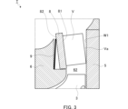
- Figure 3 is a schematic enlarged cross-sectional view showing the deformation mode of the vane plate 8 of a turbine T that does not include an inclined surface S when the vane plate 8 is heated.
- the turbine T of Figure 3 and Figure 4 below does not have an inclined surface S, as described below. Also, in Figures 3 and 4, the deformation of the vane plate 8 is exaggerated for better understanding.
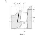
- Figure 4 is a schematic enlarged cross-sectional view showing the deformation mode of the vane plate 8 of a turbine T that does not include an inclined surface S when the vane plate 8 is cooled.
- the turbocharger 100 when the turbocharger 100 is cooled, cooling air flows through the connecting passage 62.
- the first surface 81 of the vane plate 8 that faces the connecting passage 62 becomes colder than the second surface 82 on the opposite side. Therefore, the first surface 81 contracts radially inward more than the second surface 82.
- the vane V tilts together with the vane plate 8. In this deformation mode, the innermost diameter part of the tip Va of the vane V moves away from the first wall surface W1, and a clearance is formed between the vane V and the first wall surface W1. Therefore, the efficiency of the turbine T1 decreases.
- an inclined surface S is formed on the first wall surface W1 in order to suppress the clearance formed by the deformation of the vane plate 8 as described above.
- the inclined surface S is formed in a direction that suppresses the clearance between the vane V and the first wall surface W1.
- the inclined surface S is formed on the first wall surface W1 so as to be inclined in a direction approaching the outermost diameter portion of the tip Va in a state without thermal deformation.
- the inclined surface S in a cross section parallel to and including the central axis, has a linear shape.
- the inclined surface S is formed so as to overlap the entire length of the tip Va in the radial direction.
- the angle of the inclined surface S with respect to the radial direction may be determined based on the amount of deformation of the vane plate 8 when the vane plate 8 is heated under a specified operating condition.
- the amount of deformation of the vane plate 8 may be determined by analysis or experiment.
- Figure 5 is a schematic enlarged cross-sectional view showing the behavior of the vanes V when the vane plate 8 in Figure 2 is heated. In Figure 5, the deformation of the vane plate 8 is also exaggerated for better understanding.
- the vane plate 8 when the vane plate 8 is heated, the vane plate 8 deforms so that the outermost diameter portion of the tip Va of the vane V moves away from the first wall surface W1.
- the inclined surface S is formed on the first wall surface W1 so as to be inclined in a direction approaching the outermost diameter portion of the tip Va. Therefore, the tip Va of the vane V moves to a position parallel to the inclined surface S. As a result, the contact area between the tip Va and the inclined surface S increases, and the clearance between the vane V and the first wall surface W1 is reduced.
- the inclined surface S may be formed in a direction that reduces the clearance between the vane V and the first wall surface W1 when the vane plate 8 is cooled (the situation shown in FIG. 4).
- the inclined surface S is formed on the first wall surface W1 so as to be inclined in a direction away from the outermost diameter portion of the tip Va.
- the turbine T1 includes a turbine impeller 3, a plurality of vanes V arranged circumferentially in a region radially outward of the turbine impeller 3 and protruding in the axial direction, a first wall surface W1 facing the tip Va of each of the vanes V in the axial direction, and an inclined surface S formed on the first wall surface W1 and inclined relative to the radial direction.
- the turbine T1 is also provided with an annular vane plate 8 that is disposed radially outward of the turbine impeller 3 and includes a first surface 81 facing the axial direction and a second surface 82 opposite the first surface 81, and the vanes V are provided with a vane plate 8 that protrudes from the first surface 81 of the vane plate 8, a second wall surface W2 that faces the first wall surface W1 in the axial direction between the vane plate 8 and the vanes V, and the second wall surface W2 that faces the second surface 82 of the vane plate 8, and an elastic body 9 that is disposed between the second surface 82 of the vane plate 8 and the second wall surface W2 and presses the vane plate 8 and the vanes V toward the first wall surface W1.
- the elastic body 9 can firmly press the tip Va of the vane V against the inclined surface S.
- FIG. 6 is a schematic enlarged cross-sectional view of the turbine T2 according to the second embodiment.
- the vane plate 8 and vanes V before thermal deformation are shown in solid lines, and the vane plate 8 and vanes V after thermal deformation are shown in dashed lines.
- the deformation of the vane plate 8 is exaggerated for better understanding.
- the turbine T2 according to this embodiment differs from the turbine T1 according to the first embodiment in that the inclined surface S is formed on the tip Va of the vane V instead of on the first wall surface W1.
- the turbine T2 may be the same as the turbine T1.
- the inclined surface S when the vane plate 8 is heated, the inclined surface S is formed in a direction that suppresses the clearance between the vane V and the first wall surface W1.
- the inclined surface S is formed on the tip Va such that the outermost diameter portion of the tip Va protrudes axially toward the first wall surface W1 more than the innermost diameter portion.
- the inclined surface S is formed over the entire length of the tip Va in the radial direction.
- the inclined surface S may be formed only on a portion of the tip Va in the radial direction.
- the inclined surface S may be formed only on the radially inner region of the tip Va. In this case, the remainder of the tip Va may be parallel or approximately parallel to the first wall surface W1 in a state without thermal deformation.
- the turbine T2 when the vane plate 8 is heated, the inclined surface S of the vane V moves to a position parallel to the first wall surface W1. As a result, as shown by the vane V in dashed lines, the contact area between the inclined surface S of the tip Va and the first wall surface W1 increases, and the clearance between the vane V and the first wall surface W1 is reduced. Therefore, the turbine T2 achieves substantially the same effects as the turbine T1 according to the first embodiment.
- FIG. 7 is a schematic enlarged cross-sectional view of a turbine T3 according to a third embodiment.
- the turbine T3 according to this embodiment differs from the turbine T1 according to the first embodiment in that the arrangement of the vane plate 8 and the vanes V is upside down in the axial direction compared to FIGS. 2 to 6, and the inclined surface S is formed in the turbine housing 6 instead of the bearing housing 5. Therefore, in this embodiment, a groove 51 that accommodates the vane plate 8 and the elastic body 9 is formed in the bearing housing 5.
- the turbine T3 may be the same as the turbine T1.
- the first wall surface W1 facing the tip Va of the vane V is the surface closest to the discharge port 61 among a pair of surfaces facing each other in the axial direction across the connecting flow passage 62.
- the first wall surface W1 is formed on the turbine housing 6.
- the second wall surface W2 facing the second surface 82 of the vane plate 8 is the surface farther from the discharge port 61 among a pair of surfaces facing each other in the axial direction across the connecting flow passage 62.
- the second wall surface W2 is formed on the bearing housing 5.
- the second wall surface W2 is the surface that defines the groove 51.
- the second wall surface W2 defines the groove 51 in the axial direction.
- the inclined surface S is formed in a direction that suppresses the clearance between the vane V and the first wall surface W1.
- an engine not shown
- hot exhaust gas from the engine flows through the connecting passage 62.
- the first surface 81 of the vane plate 8 that faces the connecting passage 62 becomes hotter than the second surface 82 on the opposite side. Therefore, as shown by the dashed line of the vane plate 8, the first surface 81 expands radially outward more than the second surface 82.
- the inclined surface S is formed on the first wall surface W1 so that, in a state without thermal deformation, it is inclined in a direction approaching the outermost diameter portion of the tip Va of the vane V.
- the inclined surface S is formed so as to overlap the entire length of the tip Va in the radial direction.
- the inclined surface S may be formed in a direction that suppresses the clearance between the vane V and the first wall surface W1 when the vane plate 8 is cooled.
- the inclined surface S is formed on the first wall surface W1 so that it is inclined in a direction away from the outermost diameter portion of the tip Va of the vane V in a state without thermal deformation.
- the turbine T3 when the vane plate 8 is heated, the tip Va of the vane V moves to a position parallel to the inclined surface S. As a result, the contact area between the tip Va and the inclined surface S increases, and the clearance between the vane V and the first wall surface W1 is reduced. Therefore, the turbine T3 achieves substantially the same effects as the turbine T1 according to the first embodiment.
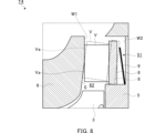
- FIG. 8 is a schematic enlarged cross-sectional view of the turbine T4 according to the fourth embodiment.
- the turbine T4 according to this embodiment differs from the turbine T3 according to the third embodiment in that the inclined surface S is shorter in the radial direction. In other respects, the turbine T4 may be the same as the turbine T3.
- the inclined surface S overlaps only a portion of the tip Va in the radial direction. In this embodiment, the inclined surface S overlaps only the radially inner region of the tip Va.
- the first wall surface W1 includes a surface that is radially outward from the inclined surface S and parallel to the radial direction.
- the tip Va of the vane V moves to a position parallel to the inclined surface S.
- the radially inner region of the tip Va is pressed against the inclined surface S. Therefore, the clearance between the vane V and the first wall surface W1 is reduced compared to when only the innermost diameter portion of the tip Va is pressed against the first wall surface W1.
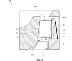
- FIG. 9 is a schematic enlarged cross-sectional view of the turbine T5 according to the fifth embodiment.
- the turbine T5 according to this embodiment differs from the turbine T3 according to the third embodiment in that a discontinuous portion 65 is formed in the first wall surface W1.
- the turbine T5 may be the same as the turbine T3. Note that the axial height of the discontinuous portion 65 is exaggerated.
- the discontinuous portion 65 protrudes from the inclined surface S in a generally axial direction.
- the discontinuous portion 65 is located radially inward relative to the tip Va of the vane V.
- the discontinuous portion 65 may be continuous in the circumferential direction.
- the discontinuous portion 65 is smoothly connected to the shroud 66 and is continuous with the shroud 66.
- the turbine T5 according to this embodiment as described above has substantially the same effects as the turbine T3 according to the third embodiment.
- the inclined surface S is formed on the first wall surface W1, which is located radially inward relative to the tip Va of the vane V and includes a discontinuous portion 65 that protrudes from the inclined surface S. With this configuration, the vane V is positioned deep relative to the discontinuous portion 65, thereby reducing the gap at the tip Va of the vane V.
- the rotating device is a turbine T1, T2, T3, T4, or T5, and the inclined surface S is formed on a vane V arranged in the connecting passage 62 or on a wall surface defining the connecting passage 62.
- the rotating device may be a centrifugal compressor C, and the inclined surface S may be formed on a diffuser vane arranged in the diffuser passage 72 or on a wall surface defining the diffuser passage 72.
- the rotating device includes an elastic body 9.
- the rotating device may not include an elastic body 9.
- the rotating device may not include a vane plate 8, and the vanes V may protrude directly from the wall surface that defines the flow path in which the vanes V are arranged.
- the inclined surface S is formed on one of the first wall surface W1 and the tip Va of the vane V.
- the inclined surface S may be formed on both the first wall surface W1 and the tip Va of the vane V.
- the angle of the inclined surface S may be determined so that the sum of the absolute value of the angle of the inclined surface S formed on the first wall surface W1 relative to the radial direction and the absolute value of the angle of the inclined surface S formed on the tip Va relative to the radial direction corresponds to the deformation amount of the vane plate 8.
- the inclined surface S formed on the first wall surface W1 and the inclined surface S formed on the tip Va are inclined in opposite directions relative to the radial direction.
- the inclined surface S may be formed on the first wall surface W1 so as to be half the angle shown in FIG. 2, and the inclined surface S may be formed on the tip Va so as to be half the angle shown in FIG. 6.
- Turbine impeller 4 Compressor impeller 8: Vane plate 9: Elastic body 65: Discontinuous portion 81: First surface 82: Second surface C: Centrifugal compressor (rotating device) S Inclined surface T1 Turbine (rotating device) T2 Turbine (rotating device) T3 Turbine (rotating device) T4 Turbine (rotating device) T5 Turbine (rotating device) V Vane Va Tip of vane W1 First wall W2 Second wall
Landscapes
- Engineering & Computer Science (AREA)
- Chemical & Material Sciences (AREA)
- Combustion & Propulsion (AREA)
- Mechanical Engineering (AREA)
- General Engineering & Computer Science (AREA)
- Supercharger (AREA)
Abstract
回転装置T1は、インペラ3と、インペラ3に対して径方向外側の領域において円周方向に沿って配置され、軸線方向に突出する複数のベーンVと、複数のベーンVの各々の突端Vaと軸線方向に対向する第1壁面W1と、第1壁面W1および複数のベーンVの突端Vaの少なくとも一方に形成され、インペラ3の径方向に対して傾斜する傾斜面Sと、を備える。
Description
本開示は、回転装置に関する。本出願は2023年6月22日に提出された日本特許出願第2023-102413号に基づく優先権の利益を主張するものであり、その内容は本出願に援用される。
タービンまたは遠心圧縮機等の回転装置は、インペラに対して径方向外側に配置されるベーンを備える場合がある。例えば、特許文献1は、タービンインペラに対して径方向外側に配置される固定翼を開示する。固定翼は、軸受ハウジングと、タービンハウジングとの間の通路に配置される。固定翼は、複数の翼体と、円環状の可動部材と、を備える。複数の翼体は、可動部材の前面に固定される。翼体の端部は、タービンハウジングに対向する。可動部材の背面と、軸受ハウジングとの間の空間には、皿ばねが配置される。皿ばねは、翼体をタービンハウジングに押し付ける。このような構成によれば、翼体とタービンハウジングとの間のクリアランスが抑制される。したがって、タービン効率の低下が抑制される。
上記のように、回転装置においては、効率の低下を抑制するために、ベーンとハウジングとの間のクリアランスを抑制することが望ましい。
本開示は、ベーンとハウジングとの間のクリアランスを抑制することができる、回転装置を提供することを目的とする。
本開示の一態様に係る回転装置は、インペラと、インペラに対して径方向外側の領域において円周方向に沿って配置され、軸線方向に突出する複数のベーンと、複数のベーンの各々の突端と軸線方向に対向する第1壁面と、第1壁面および複数のベーンの突端の少なくとも一方に形成され、インペラの径方向に対して傾斜する傾斜面と、を備える。
回転装置は、インペラに対して径方向外側に配置され、軸線方向を向く第1表面と、第1表面と反対側の第2表面と、を含む、環状のベーンプレートであって、複数のベーンは、当該ベーンプレートの第1表面から突出する、ベーンプレートと、ベーンプレートおよび複数のベーンを挟んで、第1壁面と軸線方向に対向する第2壁面であって、当該第2壁面は、ベーンプレートの第2表面に対向する、第2壁面と、ベーンプレートの第2表面と第2壁面との間に配置され、第1壁面に向かってベーンプレートおよび複数のベーンを押す弾性体と、を備えてもよい。
傾斜面は、第1壁面に形成されてもよく、第1壁面は、複数のベーンの突端に対して径方向内側に位置し、傾斜面から突出する不連続部を含んでもよい。
本開示によれば、ベーンとハウジングとの間のクリアランスを抑制することができる。
以下に添付図面を参照しながら、本開示の実施形態について詳細に説明する。かかる実施形態に示す具体的な寸法、材料および数値等は、理解を容易とするための例示にすぎず、特に断る場合を除き、本開示を限定するものではない。なお、本明細書および図面において、実質的に同一の機能、構成を有する要素については、同一の符号を付することにより重複説明を省略し、また本開示に直接関係のない要素は図示を省略する。
図1は、第1実施形態に係るタービンT1を備える過給機100の概略的な断面図である。本実施形態に係るタービンT1は、過給機100に適用される。他の実施形態では、タービンT1は、過給機100以外の設備に適用されてもよく、または、単体であってもよい。過給機100は、ハウジング1と、シャフト2と、タービンインペラ3と、コンプレッサインペラ4と、を備える。
後述するように、タービンインペラ3およびコンプレッサインペラ4は、シャフト2と一体的に回転する。したがって、本開示では、シャフト2、タービンインペラ3およびコンプレッサインペラ4の軸線方向、径方向および円周方向は、他に指示が無い限り、それぞれ単に「軸線方向」、「径方向」および「円周方向」と称され得る。また、本開示では、シャフト2、タービンインペラ3およびコンプレッサインペラ4の中心軸線は、他に指示が無い限り、単に「中心軸線」と称され得る。
ハウジング1は、ベアリングハウジング5と、タービンハウジング6と、コンプレッサハウジング7と、を含む。軸線方向において、ベアリングハウジング5の一方の端部は、Gカップリング等の締結具によってタービンハウジング6に連結される。軸線方向において、ベアリングハウジング5の他方の端部は、ボルト等の締結具によってコンプレッサハウジング7に連結される。
ベアリングハウジング5は、軸受孔5aを含む。軸受孔5aは、ベアリングハウジング5内を軸線方向に延在する。軸受孔5aは、軸受Bを収容する。軸受Bは、シャフト2を回転可能に支持する。本実施形態では、軸受Bとして、一対の転がり軸受が使用される。他の実施形態では、軸受Bとして、フルフローティング軸受またはセミフローティング軸受等の他のラジアル軸受が使用されてもよい。
軸線方向において、シャフト2の第1の端部には、タービンインペラ3が設けられる。タービンインペラ3は、シャフト2と一体的に回転する。タービンハウジング6は、タービンインペラ3を回転可能に収容する。軸線方向において、第1の端部とは反対側のシャフト2の第2の端部には、コンプレッサインペラ4が設けられる。コンプレッサインペラ4は、シャフト2と一体的に回転する。コンプレッサハウジング7は、コンプレッサインペラ4を回転可能に収容する。
コンプレッサハウジング7は、軸線方向においてベアリングハウジング5と反対側の端部に、吸気口71を含む。吸気口71は、不図示のエアクリーナに接続される。
ベアリングハウジング5およびコンプレッサハウジング7は、それらの間にディフューザ流路72を規定する。ディフューザ流路72は、環状形状を有する。ディフューザ流路72は、コンプレッサインペラ4に対して径方向外側に位置する。ディフューザ流路72は、コンプレッサインペラ4を介して吸気口71に流体連通する。
コンプレッサハウジング7は、コンプレッサスクロール流路73を含む。コンプレッサスクロール流路73は、ディフューザ流路72に対して径方向外側に位置する。コンプレッサスクロール流路73は、ディフューザ流路72と連通する。また、コンプレッサスクロール流路73は、不図示のエンジンの吸気口と流体連通する。
コンプレッサインペラ4が回転すると、吸気口71からコンプレッサハウジング7内に空気が吸引される。空気は、コンプレッサインペラ4を通る間に、遠心力によって増速および加圧される。空気は、ディフューザ流路72およびコンプレッサスクロール流路73を通る際にさらに加圧される。加圧された空気は、不図示の吐出口から流出し、エンジンの吸気口に導かれる。過給機100において、コンプレッサインペラ4およびコンプレッサハウジング7を含む部分は、遠心圧縮機Cとして機能する。
タービンハウジング6は、軸線方向においてベアリングハウジング5と反対側の端部に、吐出口61を含む。吐出口61は、不図示の排気ガス浄化装置に接続される。
タービンハウジング6は、接続流路62を含む。接続流路62は、環状形状を有する。接続流路62は、タービンインペラ3に対して径方向外側に位置する。接続流路62は、タービンインペラ3を介して吐出口61に流体連通する。接続流路62には、複数のベーンVが配置される。複数のベーンVは、タービンインペラ3に対して径方向外側の領域において、円周方向に沿って配置される。ベーンVについては、詳しくは後述する。
タービンハウジング6は、タービンスクロール流路63を含む。タービンスクロール流路63は、接続流路62に対して径方向外側に位置する。タービンスクロール流路63は、接続流路62と流体連通する。また、タービンスクロール流路63は、不図示のガス流入口と連通する。ガス流入口は、不図示のエンジンの排気マニホールドから排出される排気ガスを受け入れる。
排気ガスがガス流入口からタービンスクロール流路63に導かれ、さらに、接続流路62およびタービンインペラ3を介して吐出口61に導かれる。排気ガスは、タービンインペラ3を通る間に、タービンインペラ3を回転させる。タービンインペラ3の回転力は、シャフト2を介してコンプレッサインペラ4に伝達される。コンプレッサインペラ4が回転すると、上記のとおりに空気が加圧される。こうして、加圧された空気がエンジンの吸気口に導かれる。
続いて、ベーンVについて説明する。
図2は、図1中のA部を示す概略的な拡大断面図である。図2は、熱変形無しのベーンプレート8およびベーンVを示す。なお、本開示の図面では、より良い理解のために、後述する傾斜面Sの径方向に対する角度が誇張されている。タービンT1は、ベーンプレート8と、弾性体9と、を備える。
ベーンプレート8は、円環形状を有する。ベーンプレート8は、タービンインペラ3に対して径方向外側に配置される。ベーンプレート8は、タービンインペラ3と同心に配置される。本実施形態では、タービンハウジング6は、ベーンプレート8を配置するための溝64を含む。ベーンプレート8は、溝64に配置される。
ベーンプレート8は、軸線方向を向く第1表面81および第2表面82を含む。第2表面82は、第1表面81の反対側に位置する。第1表面81および第2表面82は、径方向に拡がる。第1表面81および第2表面82は、円環形状を有する。
ハウジング1は、ベーンプレート8およびベーンVを挟んで軸線方向に互いに対向する第1壁面W1および第2壁面W2を含む。
第1壁面W1は、ベーンVの突端Vaに軸線方向に対向する。本実施形態では、第1壁面W1は、接続流路62を挟んで軸線方向に互いに対向する一対の表面のうち、吐出口61から離れた表面である。本実施形態では、第1壁面W1は、ベアリングハウジング5に形成される。
第2壁面W2は、ベーンプレート8の第2表面82に軸線方向に対向する。本実施形態では、第2壁面W2は、接続流路62を挟んで軸線方向に互いに対向する一対の表面のうち、吐出口61に近い表面である。本実施形態では、第2壁面W2は、タービンハウジング6に形成される。本実施形態では、第2壁面W2は、溝64を画定する表面である。第2壁面W2は、溝64を軸線方向に画定する。
第1壁面W1および第2壁面W2は、径方向に拡がる。第1壁面W1および第2壁面W2は、円環形状を有する。本実施形態では、接続流路62は、第1壁面W1と、ベーンプレート8の第1表面81とによって画定される。
ベーンVは、ベーンプレート8の第1表面81から軸線方向に突出する。ベーンVは、第1表面81に固定される。例えば、ベーンVは、ベーンプレート8と一体的に形成されてもよい。代替的に、ベーンVは、ベーンプレート8と別個に形成され、ベーンプレート8に連結されてもよい。ベーンVの突端Vaは、第1壁面W1に対向する。
弾性体9は、ベーンプレート8の第2表面82と、タービンハウジング6の第2壁面W2との間に配置される。本実施形態では、弾性体9は、溝64に配置される。弾性体9は、第1壁面W1に向かって、ベーンプレート8およびベーンVを押す。したがって、ベーンVの突端Vaは、第1壁面W1に押し付けられる。本実施形態では、弾性体9は皿ばねである。他の実施形態では、弾性体9として、例えば、複数のコイルバネ等、他の弾性体が使用されてもよい。本実施形態では、弾性体9は、截頭円錐形状を有する。弾性体9は、タービンインペラ3と同心に配置される。
図3は、傾斜面Sを含まないタービンTのベーンプレート8が加熱されるときのベーンプレート8の変形モードを示す概略的な拡大断面図である。図3および以下の図4のタービンTは、後述する傾斜面Sを備えない。また、図3および4では、より良い理解のために、ベーンプレート8の変形は誇張されている。
例えば、不図示のエンジンの加速時には、エンジンからの熱い排気ガスが接続流路62を流れる。この場合、ベーンプレート8のうち、接続流路62に面する第1表面81が、反対側の第2表面82よりも熱くなる。したがって、第1表面81が、第2表面82よりも径方向外側に膨張する。ベーンVは、ベーンプレート8と一緒に傾く。この変形モードでは、ベーンVの突端Vaの最外径部が第1壁面W1から離れ、ベーンVと第1壁面W1との間にクリアランスが形成される。したがって、タービンT1の効率が低下する。
図4は、傾斜面Sを含まないタービンTのベーンプレート8が冷却されるときのベーンプレート8の変形モードを示す概略的な拡大断面図である。
例えば、過給機100の冷却時には、冷却エアが接続流路62を流れる。この場合、ベーンプレート8のうち、接続流路62に面する第1表面81が、反対側の第2表面82よりも冷たくなる。したがって、第1表面81が、第2表面82よりも径方向内側に収縮する。ベーンVは、ベーンプレート8と一緒に傾く。この変形モードでは、ベーンVの突端Vaの最内径部が第1壁面W1から離れ、ベーンVと第1壁面W1との間にクリアランスが形成される。したがって、タービンT1の効率が低下する。
図2を参照して、本実施形態では、上記のようなベーンプレート8の変形によって形成されるクリアランスを抑制するために、第1壁面W1に傾斜面Sが形成される。本実施形態では、ベーンプレート8が加熱されるとき(図3に示される状況)に、ベーンVと第1壁面W1との間のクリアランスを抑制する方向に傾斜面Sが形成される。
具体的には、図3に示されるように、ベーンプレート8が加熱されるときには、ベーンVの突端Vaの最外径部が、第1壁面W1から離れる。図2を参照して、このような変形に追従するために、本実施形態では、傾斜面Sは、熱変形無しの状態において、突端Vaの最外径部に近付く方向に傾くように、第1壁面W1上に形成される。本実施形態では、中心軸線に平行でかつ中心軸線を含む断面において、傾斜面Sは、直線形状を有する。本実施形態では、傾斜面Sは、径方向において突端Vaの全長と重複するように形成される。例えば、径方向に対する傾斜面Sの角度は、所定の運転条件下でベーンプレート8が加熱されるときの、ベーンプレート8の変形量に基づいて決定されてもよい。例えば、ベーンプレート8の変形量は、解析または実験によって求められてもよい。
図5は、図2中のベーンプレート8が加熱されるときのベーンVの挙動を示す概略的な拡大断面図である。図5においても、より良い理解のために、ベーンプレート8の変形は誇張されている。
上記のように、ベーンプレート8が加熱されるときには、ベーンVの突端Vaの最外径部が第1壁面W1から離れるように、ベーンプレート8が変形する。しかしながら、本実施形態では、傾斜面Sが、突端Vaの最外径部に近付く方向に傾くように、第1壁面W1上に形成される。したがって、ベーンVの突端Vaは、傾斜面Sに平行な姿勢に移動する。その結果、突端Vaと傾斜面Sとの間の接触面積が増大し、ベーンVと第1壁面W1との間のクリアランスが抑制される。
他の実施形態では、ベーンプレート8が冷却されるとき(図4に示される状況)に、ベーンVと第1壁面W1との間のクリアランスを抑制する方向に傾斜面Sが形成されてもよい。この場合、傾斜面Sは、突端Vaの最外径部から離れる方向に傾くように、第1壁面W1上に形成される。
以上のような本実施形態に係るタービンT1は、タービンインペラ3と、タービンインペラ3に対して径方向外側の領域において円周方向に沿って配置され、軸線方向に突出する複数のベーンVと、複数のベーンVの各々の突端Vaと軸線方向に対向する第1壁面W1と、第1壁面W1に形成され、径方向に対して傾斜する傾斜面Sと、を備える。このような構成によれば、ベーンVを支持する壁面が加熱または冷却されるときに、ベーンVの突端Vaは、傾斜面Sに平行な姿勢に移動する。その結果、突端Vaと傾斜面Sとの間の接触面積が増大し、ベーンVと第1壁面W1との間のクリアランスが抑制される。
また、タービンT1は、タービンインペラ3に対して径方向外側に配置され、軸線方向を向く第1表面81と、第1表面81と反対側の第2表面82と、を含む、環状のベーンプレート8であって、複数のベーンVは、当該ベーンプレート8の第1表面81から突出する、ベーンプレート8と、ベーンプレート8および複数のベーンVを挟んで、第1壁面W1と軸線方向に対向する第2壁面W2であって、当該第2壁面W2は、ベーンプレート8の第2表面82に対向する、第2壁面W2と、ベーンプレート8の第2表面82と第2壁面W2との間に配置され、第1壁面W1に向かってベーンプレート8およびベーンVを押す弾性体9と、を備える。このような構成によれば、弾性体9によって、ベーンVの突端Vaをしっかりと傾斜面Sに押し付けることができる。
続いて、他の実施形態について説明する。
図6は、第2実施形態に係るタービンT2の概略的な拡大断面図である。図6ならびに以下の図7,8および9では、熱変形前のベーンプレート8およびベーンVが実線で示され、熱変形後のベーンプレート8およびベーンVが破線で示される。また、図6,7,8および9では、より良い理解のために、ベーンプレート8の変形は誇張されている。
本実施形態に係るタービンT2は、傾斜面Sが、第1壁面W1に代えて、ベーンVの突端Vaに形成される点で、第1実施形態に係るタービンT1と異なる。他の点については、タービンT2は、タービンT1と同じであってもよい。
本実施形態では、ベーンプレート8が加熱されるときに、ベーンVと第1壁面W1との間のクリアランスを抑制する方向に傾斜面Sが形成される。具体的には、本実施形態では、傾斜面Sは、突端Vaの最外径部が第1壁面W1に向かって最内径部よりも軸線方向に突出するように、突端Va上に形成される。本実施形態では、傾斜面Sは、径方向において突端Vaの全長にわたって形成される。他の実施形態では、傾斜面Sは、径方向において突端Vaの一部にのみ形成されてもよい。例えば、傾斜面Sは、突端Vaの径方向内側領域のみに形成されてもよい。この場合、突端Vaの残りは、熱変形無しの状態において、第1壁面W1に平行または概ね平行であってもよい。
以上のような本実施形態に係るタービンT2では、ベーンプレート8が加熱されるときに、ベーンVの傾斜面Sは、第1壁面W1に平行な姿勢に移動する。その結果、破線のベーンVで示されるように、突端Vaの傾斜面Sと第1壁面W1との間の接触面積が増大し、ベーンVと第1壁面W1との間のクリアランスが抑制される。したがって、タービンT2は、第1実施形態に係るタービンT1と概ね同様な効果を奏する。
図7は、第3実施形態に係るタービンT3の概略的な拡大断面図である。本実施形態に係るタービンT3は、ベーンプレート8およびベーンVの配置が軸線方向において図2から6と逆さであり、傾斜面Sが、ベアリングハウジング5に代えて、タービンハウジング6に形成される点で、第1実施形態に係るタービンT1と異なる。したがって、本実施形態では、ベーンプレート8および弾性体9を収容する溝51が、ベアリングハウジング5に形成される。他の点については、タービンT3は、タービンT1と同じであってもよい。
本実施形態では、ベーンVの突端Vaに対向する第1壁面W1は、接続流路62を挟んで軸線方向に互いに対向する一対の表面のうち、吐出口61に近い表面である。本実施形態では、第1壁面W1は、タービンハウジング6に形成される。本実施形態では、ベーンプレート8の第2表面82に対向する第2壁面W2は、接続流路62を挟んで軸線方向に互いに対向する一対の表面のうち、吐出口61から離れた表面である。本実施形態では、第2壁面W2は、ベアリングハウジング5に形成される。本実施形態では、第2壁面W2は、溝51を画定する表面である。第2壁面W2は、溝51を軸線方向に画定する。
本実施形態では、ベーンプレート8が加熱されるときに、ベーンVと第1壁面W1との間のクリアランスを抑制する方向に傾斜面Sが形成される。具体的には、不図示のエンジンの加速時には、エンジンからの熱い排気ガスが接続流路62を流れる。この場合、ベーンプレート8のうち、接続流路62に面する第1表面81が、反対側の第2表面82よりも熱くなる。したがって、破線のベーンプレート8で示されるように、第1表面81が、第2表面82よりも径方向外側に膨張する。
本実施形態では、傾斜面Sは、熱変形無しの状態において、ベーンVの突端Vaの最外径部に近付く方向に傾くように、第1壁面W1上に形成される。本実施形態では、傾斜面Sは、径方向において突端Vaの全長と重複するように形成される。
他の実施形態では、ベーンプレート8が冷却されるときに、ベーンVと第1壁面W1との間のクリアランスを抑制する方向に傾斜面Sが形成されてもよい。この場合、傾斜面Sは、熱変形無しの状態において、ベーンVの突端Vaの最外径部から離れる方向に傾くように、第1壁面W1上に形成される。
以上のような本実施形態に係るタービンT3では、ベーンプレート8が加熱されるときに、ベーンVの突端Vaは、傾斜面Sに平行な姿勢に移動する。その結果、突端Vaと傾斜面Sとの間の接触面積が増大し、ベーンVと第1壁面W1との間のクリアランスが抑制される。したがって、タービンT3は、第1実施形態に係るタービンT1と概ね同様な効果を奏する。
図8は、第4実施形態に係るタービンT4の概略的な拡大断面図である。本実施形態に係るタービンT4は、傾斜面Sが径方向に短い点で、第3実施形態に係るタービンT3と異なる。他の点については、タービンT4は、タービンT3と同じであってもよい。
本実施形態では、傾斜面Sは、径方向において突端Vaの一部とのみ重複する。本実施形態では、傾斜面Sは、突端Vaの径方向内側領域のみと重複する。第1壁面W1は、傾斜面Sに対して径方向外側に、径方向に平行な表面を含む。
以上のような本実施形態に係るタービンT4では、ベーンプレート8が加熱されるときに、ベーンVの突端Vaは、傾斜面Sに平行な姿勢に移動する。その結果、突端Vaの径方向内側領域が、傾斜面Sに押し付けられる。したがって、突端Vaの最内径部のみが第1壁面W1に押し付けられる場合に比して、ベーンVと第1壁面W1との間のクリアランスが抑制される。
図9は、第5実施形態に係るタービンT5の概略的な拡大断面図である。本実施形態に係るタービンT5は、第1壁面W1に不連続部65が形成される点で、第3実施形態に係るタービンT3と異なる。他の点については、タービンT5は、タービンT3と同じであってもよい。なお、不連続部65の軸線方向における高さは、誇張されている。
不連続部65は、傾斜面Sから、概ね軸線方向に突出する。不連続部65は、ベーンVの突端Vaに対して、径方向内側に位置する。例えば、不連続部65は、円周方向に連続してもよい。本実施形態では、不連続部65は、シュラウド66とは滑らかに接続され、シュラウド66とは連続している。
以上のような本実施形態に係るタービンT5は、第3実施形態に係るタービンT3と概ね同様な効果を奏する。特に、タービンT5では、傾斜面Sは、第1壁面W1に形成され、第1壁面W1は、ベーンVの突端Vaに対して径方向内側に位置し、傾斜面Sから突出する不連続部65を含む。このような構成によれば、不連続部65に対してベーンVを深く配置することで、ベーンVの突端Vaでの間隙を低減することができる。
以上、添付図面を参照しながら実施形態について説明したが、本開示は上記実施形態に限定されない。当業者であれば、特許請求の範囲に記載された範疇において、各種の変更例または修正例に想到し得ることは明らかであり、それらについても当然に本開示の技術的範囲に属するものと了解される。
例えば、上記の実施形態では、回転装置は、タービンT1,T2,T3,T4,T5であり、傾斜面Sは、接続流路62に配置されるベーンV、または、接続流路62を画定する壁面に形成される。他の実施形態では、例えば、回転装置は、遠心圧縮機Cであってもよく、傾斜面Sは、ディフューザ流路72に配置されるディフューザベーン、または、ディフューザ流路72を画定する壁面に形成されてもよい。
また、上記の実施形態では、回転装置は、弾性体9を備える。他の実施形態では、回転装置は、弾性体9を備えなくてもよい。この場合、回転装置は、ベーンプレート8を備えなくてもよく、ベーンVは、ベーンVが配置される流路を画定する壁面から直接的に突出してもよい。
また、上記の実施形態では、傾斜面Sは、第1壁面W1およびベーンVの突端Vaの一方に形成される。他の実施形態では、傾斜面Sは、第1壁面W1およびベーンVの突端Vaの双方に形成されてもよい。この場合、例えば、第1壁面W1に形成される傾斜面Sの径方向に対する角度の絶対値と、突端Vaに形成される傾斜面Sの径方向に対する角度の絶対値と、の合計が、ベーンプレート8の変形量に相当するように、傾斜面Sの角度が決定されてもよい。この場合、第1壁面W1に形成される傾斜面Sと、突端Vaに形成される傾斜面Sとは、径方向に対して互いに逆方向に傾斜する。例えば、この場合、図2に示される角度の半分となるように第1壁面W1に傾斜面Sが形成され、かつ、図6に示される角度の半分となるように突端Vaに傾斜面Sが形成されてもよい。
3 タービンインペラ
4 コンプレッサインペラ
8 ベーンプレート
9 弾性体
65 不連続部
81 第1表面
82 第2表面
C 遠心圧縮機(回転装置)
S 傾斜面
T1 タービン(回転装置)
T2 タービン(回転装置)
T3 タービン(回転装置)
T4 タービン(回転装置)
T5 タービン(回転装置)
V ベーン
Va ベーンの突端
W1 第1壁面
W2 第2壁面
4 コンプレッサインペラ
8 ベーンプレート
9 弾性体
65 不連続部
81 第1表面
82 第2表面
C 遠心圧縮機(回転装置)
S 傾斜面
T1 タービン(回転装置)
T2 タービン(回転装置)
T3 タービン(回転装置)
T4 タービン(回転装置)
T5 タービン(回転装置)
V ベーン
Va ベーンの突端
W1 第1壁面
W2 第2壁面
Claims (3)
- インペラと、
前記インペラに対して径方向外側の領域において円周方向に沿って配置され、軸線方向に突出する複数のベーンと、
前記複数のベーンの各々の突端と前記軸線方向に対向する第1壁面と、
前記第1壁面および前記複数のベーンの前記突端の少なくとも一方に形成され、前記インペラの径方向に対して傾斜する傾斜面と、
を備える、回転装置。 - 前記インペラに対して径方向外側に配置され、前記軸線方向を向く第1表面と、前記第1表面と反対側の第2表面と、を含む、環状のベーンプレートであって、前記複数のベーンは、当該ベーンプレートの前記第1表面から突出する、ベーンプレートと、
前記ベーンプレートおよび前記複数のベーンを挟んで、前記第1壁面と前記軸線方向に対向する第2壁面であって、当該第2壁面は、前記ベーンプレートの前記第2表面に対向する、第2壁面と、
前記ベーンプレートの前記第2表面と前記第2壁面との間に配置され、前記第1壁面に向かって前記ベーンプレートおよび前記複数のベーンを押す弾性体と、
を備える、請求項1に記載の回転装置。 - 前記傾斜面は、前記第1壁面に形成され、
前記第1壁面は、前記複数のベーンの前記突端に対して径方向内側に位置し、前記傾斜面から突出する不連続部を含む、
請求項1または2に記載の回転装置。
Applications Claiming Priority (2)
| Application Number | Priority Date | Filing Date | Title |
|---|---|---|---|
| JP2023102413 | 2023-06-22 | ||
| JP2023-102413 | 2023-06-22 |
Publications (1)
| Publication Number | Publication Date |
|---|---|
| WO2024262099A1 true WO2024262099A1 (ja) | 2024-12-26 |
Family
ID=93935313
Family Applications (1)
| Application Number | Title | Priority Date | Filing Date |
|---|---|---|---|
| PCT/JP2024/008777 WO2024262099A1 (ja) | 2023-06-22 | 2024-03-07 | 回転装置 |
Country Status (1)
| Country | Link |
|---|---|
| WO (1) | WO2024262099A1 (ja) |
Citations (7)
| Publication number | Priority date | Publication date | Assignee | Title |
|---|---|---|---|---|
| JPS6361545U (ja) * | 1986-10-09 | 1988-04-23 | ||
| JPH07259796A (ja) * | 1994-03-18 | 1995-10-09 | Hitachi Ltd | 遠心圧縮機 |
| JP2005320970A (ja) * | 2004-05-06 | 2005-11-17 | Cummins Inc | 可変幾何学的形態タービンを使用する内燃機関におけるあと処理システム用の排ガスの温度を決定する方法 |
| WO2009046504A1 (en) * | 2007-10-09 | 2009-04-16 | Atlas Copco Airpower, Naamloze Vennootschap | Improved turbo-compressor |
| WO2012036122A1 (ja) * | 2010-09-13 | 2012-03-22 | 株式会社Ihi | 固定翼式ターボチャージャ |
| WO2014102962A1 (ja) * | 2012-12-27 | 2014-07-03 | 三菱重工業株式会社 | 可変容量型排気ターボ過給機 |
| WO2016031017A1 (ja) * | 2014-08-28 | 2016-03-03 | 三菱重工業株式会社 | 膨張タービン及びターボチャージャ |
-
2024
- 2024-03-07 WO PCT/JP2024/008777 patent/WO2024262099A1/ja unknown
Patent Citations (7)
| Publication number | Priority date | Publication date | Assignee | Title |
|---|---|---|---|---|
| JPS6361545U (ja) * | 1986-10-09 | 1988-04-23 | ||
| JPH07259796A (ja) * | 1994-03-18 | 1995-10-09 | Hitachi Ltd | 遠心圧縮機 |
| JP2005320970A (ja) * | 2004-05-06 | 2005-11-17 | Cummins Inc | 可変幾何学的形態タービンを使用する内燃機関におけるあと処理システム用の排ガスの温度を決定する方法 |
| WO2009046504A1 (en) * | 2007-10-09 | 2009-04-16 | Atlas Copco Airpower, Naamloze Vennootschap | Improved turbo-compressor |
| WO2012036122A1 (ja) * | 2010-09-13 | 2012-03-22 | 株式会社Ihi | 固定翼式ターボチャージャ |
| WO2014102962A1 (ja) * | 2012-12-27 | 2014-07-03 | 三菱重工業株式会社 | 可変容量型排気ターボ過給機 |
| WO2016031017A1 (ja) * | 2014-08-28 | 2016-03-03 | 三菱重工業株式会社 | 膨張タービン及びターボチャージャ |
Similar Documents
| Publication | Publication Date | Title |
|---|---|---|
| EP2180160B1 (en) | Turbo charger | |
| US7351042B2 (en) | Structure of scroll of variable-throat exhaust turbocharger and method for manufacturing the turbocharger | |
| EP3904693B1 (en) | Centrifugal compressor and air conditioning apparatus | |
| US9103223B2 (en) | Shaft sealing device and rotating machine comprising same | |
| JP6542246B2 (ja) | 可変容量型過給機 | |
| JPS6237214B2 (ja) | ||
| WO2015190470A1 (ja) | 可変ノズルユニット及び可変容量型過給機 | |
| JP4625158B2 (ja) | 遠心式コンプレッサ | |
| JP2013253521A (ja) | 可変ノズルユニット及び可変容量型過給機 | |
| WO2022113619A1 (ja) | 過給機 | |
| JP7315109B2 (ja) | 過給機 | |
| US11459907B2 (en) | Variable capacity turbocharger | |
| CN103806948B (zh) | 涡轮增压器和用于它的可变喷嘴筒体 | |
| JP2012107527A (ja) | ターボチャージャ | |
| WO2024262099A1 (ja) | 回転装置 | |
| JP2013253520A (ja) | 可変ノズルユニット及び可変容量型過給機 | |
| JP6146507B2 (ja) | 可変ノズルユニット及び可変容量型過給機 | |
| WO2024237107A1 (ja) | 回転装置 | |
| CN212615553U (zh) | 轴承壳体、壳体组件和涡轮增压器 | |
| JP6969670B2 (ja) | 過給機 | |
| JP2024164896A (ja) | 回転装置 | |
| WO2025052734A1 (ja) | 回転装置 | |
| CN114981528B (zh) | 可变容量型增压器 | |
| JP7651986B2 (ja) | 遠心式回転装置 | |
| JP7643214B2 (ja) | 遠心式回転装置 |
Legal Events
| Date | Code | Title | Description |
|---|---|---|---|
| 121 | Ep: the epo has been informed by wipo that ep was designated in this application |
Ref document number: 24825510 Country of ref document: EP Kind code of ref document: A1 |