WO2024262002A1 - 液滴除去性能の評価方法 - Google Patents
液滴除去性能の評価方法 Download PDFInfo
- Publication number
- WO2024262002A1 WO2024262002A1 PCT/JP2023/023305 JP2023023305W WO2024262002A1 WO 2024262002 A1 WO2024262002 A1 WO 2024262002A1 JP 2023023305 W JP2023023305 W JP 2023023305W WO 2024262002 A1 WO2024262002 A1 WO 2024262002A1
- Authority
- WO
- WIPO (PCT)
- Prior art keywords
- droplet
- sample
- contact area
- hysteresis
- droplet removal
- Prior art date
- Legal status (The legal status is an assumption and is not a legal conclusion. Google has not performed a legal analysis and makes no representation as to the accuracy of the status listed.)
- Ceased
Links
Images




Classifications
-
- G—PHYSICS
- G01—MEASURING; TESTING
- G01N—INVESTIGATING OR ANALYSING MATERIALS BY DETERMINING THEIR CHEMICAL OR PHYSICAL PROPERTIES
- G01N13/00—Investigating surface or boundary effects, e.g. wetting power; Investigating diffusion effects; Analysing materials by determining surface, boundary, or diffusion effects
Definitions
- This disclosure relates to a method for evaluating droplet removal performance.
- Non-Patent Document 1 shows an example in which water droplets roll off even when tilted by just a few degrees, even when the static contact angle is about 160°, and an example in which water droplets do not slide off even when tilted by 90°.
- Non-Patent Document 3 hysteresis, which is defined as the difference between the advancing contact angle and the receding contact angle. The smaller the hysteresis, the higher the droplet removability can be evaluated.
- the contact area of the droplet increases with an increase in the tilt angle, it may not be possible to accurately determine droplet removability using hysteresis alone.
- the contact area may expand downward due to gravity, but if the force with which the sample attracts the droplet is greater than the force with which it repels it, or if the sample has a special pattern (Non-Patent Document 4), the contact area may also expand upward.
- This disclosure has been made in light of the above, and aims to more appropriately evaluate the removability of droplets.
- a method for evaluating droplet removal performance involves dropping a droplet onto the surface of a material to be evaluated, tilting the material to be evaluated after dropping the droplet, measuring the hysteresis of the droplet and the size of the contact area between the droplet and the material to be evaluated when the material to be evaluated is tilted, and evaluating the droplet removal performance of the material to be evaluated using the measured values of the hysteresis and the size of the contact area.
- This disclosure makes it possible to more appropriately evaluate the removability of droplets.
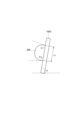
- FIG. 1 is a diagram showing an example of an advancing contact angle and a receding contact angle.
- FIG. 2 is a diagram showing an example of the advancing contact angle and the receding contact angle.
- FIG. 3 is a diagram showing an example of the advancing contact angle and the receding contact angle.
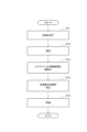
- FIG. 4 is a flowchart showing an example of the process flow of the droplet removal performance evaluation method.
- FIG. 5 is a diagram showing an example of hysteresis and a normalized value of the hysteresis.
- FIG. 6 is a diagram showing an example of the contact area and the normalized value of the contact area.
- FIG. 7 is a diagram showing an example of the droplet removal indicator.
- FIG. 1 is a diagram showing an example of an advancing contact angle and a receding contact angle.
- FIG. 2 is a diagram showing an example of the advancing contact angle and the receding contact angle.
- FIG. 3 is a diagram showing an example of the advancing
- FIG. 8 is a diagram illustrating an example of a configuration of an evaluation device.
- FIG. 9 is a diagram showing an example of the measurement results of hysteresis and contact area.
- FIG. 10 is a diagram showing an example of hysteresis and a normalized value of the hysteresis.
- FIG. 11 is a diagram illustrating an example of the contact area and the normalized value of the contact area.
- FIG. 12 is a diagram showing an example of the droplet removal indicator.
- FIG. 13 is a diagram illustrating an example of a hardware configuration of the evaluation device.
- a droplet 200 is dropped onto the surfaces of Sample 100A, Sample 100B, and Sample 100C, and the inclination angle ⁇ is increased.
- the advancing contact angle ⁇ a and receding contact angle ⁇ r at the inclination angle ⁇ just before the droplet 200 slides off are measured.
- the hysteresis is calculated as ⁇ a - ⁇ r.
- ⁇ a 100°
- ⁇ r 100°
- the hysteresis ⁇ a - ⁇ r 0°.
- ⁇ r 70°
- the hysteresis ⁇ a - ⁇ r 50°.
- the hysteresis of Sample 100A is smaller than that of Sample 100B, so it can be evaluated that Sample 100A has better droplet removal performance.
- the contact area of the droplet 200 is larger in sample 100C than in sample 100A (Lc > La). Comparing only the hysteresis, the droplet removal performance of sample 100A and sample 100C is evaluated to be the same.
- sample 100C if it is considered that the force (gravity) acting on the droplet 200 is used to increase the contact area of the droplet 200, it is considered that the force required to remove the droplet 200 is reduced in sample 100C compared to sample 100A. In other words, it is considered that sample 100C has lower droplet removal performance than sample 100A.
- Hysteresis alone does not monitor the anisotropic increase in contact area, so droplet removal performance cannot be evaluated appropriately.
- An anisotropic increase in contact area occurs when the force that attracts the droplets of the sample is greater than the force that repels them, causing the contact area to expand in the upward direction.
- the droplet removal performance of the water- and oil-repellent material was evaluated using hysteresis and the size of the contact area. Specifically, the droplet removal performance was evaluated using the following formula as a new droplet removal index.
- the normalized value of hysteresis is the value obtained by normalizing the hysteresis measured for each sample to a range from 0 to 1.
- the normalized value of the size of the contact area is the value obtained by normalizing the size of the contact area between the droplet and the sample to a range from 0 to 1.
- the size of the contact area is the contact area between the droplet and the sample, or the contact distance when the contact area between the droplet and the sample is viewed from the side.
- the normalized value of the size of the contact area may be a value obtained by normalizing the amount of change in the size of the contact area when the sample is tilted.
- step S11 the device drops a droplet onto the sample to be evaluated, and while photographing the droplet, changes the tilt angle of the sample from 0° to 90° in 1° increments.
- the droplet is photographed so that the contact angle of the droplet and the size of the contact area between the droplet and the sample can be determined.
- the tilt angle is not limited to 0° to 90°, and may be changed from any tilt angle to any other tilt angle.
- step S12 the device measures the advancing contact angle, receding contact angle, and contact area at the tilt angle before the droplet slides off. If the droplet does not slide off, the device measures the advancing contact angle, receding contact angle, and contact area when the tilt angle is 90°.
- the advancing contact angle, receding contact angle, and contact area can be measured using the image captured in step S11.
- the area of a circle whose diameter is the length of the contact area on the image may be used as the contact area.
- the length of the contact area between the droplet and the sample may be used instead of the contact area.
- the amount of change in the contact area or the amount of change in the length of the contact area may also be used. When the amount of change is used, the size of the contact area is measured without tilting the sample. In this disclosure, the contact area may be interpreted as the length of the contact area.
- steps S11 and S12 are performed for all samples.
- the processes of steps S11 and S12 may be performed multiple times for each sample to find the average of the measured values, and the average may be used as the measurement result for that sample. Droplets may also be dropped into multiple locations for each sample, measurements may be taken at each location, and the average of the measured values may be found.
- step S13 the device standardizes the hysteresis and contact area. For example, for hysteresis, 0° is set to 0, and the maximum hysteresis among each sample is set to 1, and the hysteresis of each sample is standardized. For contact area, the minimum is set to 0, and the maximum contact area among each sample is set to 1, and the contact area of each sample is standardized. When standardizing, the operator may determine the maximum value of hysteresis and the maximum value of contact area.
- Figure 5 shows an example of the hysteresis and normalized hysteresis values for samples A, B, and C.
- Hysteresis is calculated by subtracting the receding contact angle from the advancing contact angle.
- sample B's hysteresis is maximum at 50°, so for samples A, B, and C, the hysteresis from 0° to 50° is converted to 0 to 1 to normalize the hysteresis.
- Figure 6 shows an example of the contact area and normalized value of the contact area for samples A, B, and C.
- the contact area of sample C is the largest at 20, so for samples A, B, and C, the contact area of 0 to 20 is converted to 0 to 1 to normalize the contact area.
- step S14 the device substitutes the normalized hysteresis value and the normalized contact area value of each sample into the above formula to derive the droplet removal index for each sample.
- Figure 7 shows an example of the droplet removal index for sample A, sample B, and sample C.
- step S15 the device compares the droplet removal index of each sample and evaluates the droplet removal performance of each sample.
- the higher the droplet removal index obtained in step S14 the higher the droplet removal performance of the sample can be evaluated.
- sample A can be evaluated as having the highest droplet removal performance
- sample C as having the next highest droplet removal performance after sample A
- sample B as having the lowest droplet removal performance.
- the operator may determine a reference value for the droplet removal index and compare the droplet removal index of each sample with the reference value to evaluate the droplet removal performance of each sample.
- evaluation is performed using only hysteresis, the droplet removal performance of sample A and sample C are evaluated to be about the same, but by using the evaluation method of this embodiment, the difference in droplet removal performance between sample A and sample C can be more accurately evaluated.
- evaluation device An example of the configuration of an evaluation device for droplet removal performance will be described with reference to Fig. 8.
- the evaluation device 10 shown in the figure includes an input unit 11, an analysis unit 12, a calculation unit 13, and an evaluation unit 14.
- the input unit 11 inputs a still image or video of the droplet.
- the input unit 11 identifies the frame in the video where the droplet begins to slide down, and transmits the previous frame to the analysis unit 12.
- the input unit 11 may also be equipped with a camera to capture the droplet.
- the analysis unit 12 analyzes the captured image of the droplet to determine the advancing contact angle, receding contact angle, and contact area.
- the analysis unit 12 may display the image and accept input from the operator of the advancing contact angle, receding contact angle, and a line segment indicating the contact area.
- the calculation unit 13 obtains the normalized values of the hysteresis and contact area, and calculates the droplet removal index for each sample.
- the evaluation unit 14 evaluates the droplet removal performance of each sample based on the droplet removal index of each sample.
- the hysteresis and contact size were determined for droplets at three locations for each sample, and the average was calculated. The average value for each sample was used to calculate the droplet removal index.
- Figures 10 and 11 show the normalized values of the hysteresis and contact area size for each sample.
- Figure 12 shows the droplet removal index for each sample. Since sample 3 has the largest droplet removal index, the droplet removal performance of sample 3 was evaluated as high, while the droplet removal performance of samples 1 and 2 was evaluated as low.
- the advancing contact angle and receding contact angle were measured using the sliding method, but they may also be measured using the expansion/contraction method.
- the method for evaluating the droplet removal performance of this embodiment involves dropping droplets 200 onto the surfaces of samples 100A, 100B, and 100C, tilting samples 100A, 100B, and 100C after dropping droplets 200, measuring the hysteresis and the size of the contact area when samples 100A, 100B, and 100C are tilted, and evaluating the droplet removal performance of samples 100A, 100B, and 100C using the measured values of hysteresis and the size of the contact area. This allows for a more appropriate evaluation of the droplet removal performance.
- the evaluation device 10 described above can be, for example, a general-purpose computer system including a central processing unit (CPU) 901, memory 902, storage 903, communication device 904, input device 905, and output device 906, as shown in FIG. 13.
- the evaluation device 10 is realized by the CPU 901 executing a predetermined program loaded onto the memory 902.
- This program can be recorded on a non-transitory computer-readable recording medium such as a magnetic disk, optical disk, or semiconductor memory, or can be distributed via a network.
Landscapes
- Physics & Mathematics (AREA)
- Health & Medical Sciences (AREA)
- Life Sciences & Earth Sciences (AREA)
- Chemical & Material Sciences (AREA)
- Analytical Chemistry (AREA)
- Biochemistry (AREA)
- General Health & Medical Sciences (AREA)
- General Physics & Mathematics (AREA)
- Immunology (AREA)
- Pathology (AREA)
- Length Measuring Devices By Optical Means (AREA)
Abstract
サンプル100A,100B,100Cの表面に液滴200を滴下し、液滴200を滴下後に、サンプル100A,100B,100Cを傾斜させ、サンプル100A,100B,100Cを傾斜させたときのヒステリシスと接触部分のサイズを測定し、ヒステリシスと接触部分のサイズの測定値を用いてサンプル100A,100B,100Cの液滴除去性能を評価する。
Description
本開示は、液滴除去性能の評価方法に関する。
撥水撥油材料の撥水撥油性の評価に、静的接触角が指標として使われてきたが、静的接触角の優劣関係は必ずしも液滴の除去性の優劣関係と対応するものではない(非特許文献1)。非特許文献2では、静的接触角が約160°であっても、数度傾けただけで水滴が転がり落ちる例と、傾斜角90°でも水滴が滑落しない例が示されている。
そのため、液滴の除去性は、前進接触角と後退接触角の差で定義されるヒステリシスで評価することが有効である(非特許文献3)。ヒステリシスが小さいほど液滴除去性が高いと評価できる。
「滑落角とは」、[online]、協和界面科学株式会社、[2023年4月25日検索]、インターネット〈URL:https://www.face-kyowa.co.jp/science/theory/what_sliding_angle.html〉
穂積篤、外4名、「液体の滑落性に着目した撥液処理の開発動向」、表面技術、一般社団法人表面技術協会、2016年9月、第67巻、第9号、pp.452-460
「液除去性評価」、[online]、協和界面科学株式会社、[2023年4月25日検索]、インターネット〈URL:https://www.face-kyowa.co.jp/science/literature/contactangle07.html〉
「研究紹介『微量液体操作デバイス』」、[online]、国立大学法人九州工業大学、[2023年4月25日検索]、インターネット〈URL:https://www.life.kyutech.ac.jp/~yasuda/jp/research/liquidhandling/index.html〉
「接触角(ぬれ性)とは」、[online]、協和界面科学株式会社、[2023年4月25日検索]、インターネット〈URL:https://www.face-kyowa.co.jp/science/theory/what_contact_angle/〉
傾斜角の増加に伴い液滴の接触面積が増加した場合、ヒステリシスのみでは正確に液滴除去性を判定できない可能性がある。重力で下方向に接触面積が広がることもあるが、サンプルが液滴を吸着する力が弾く力より大きい場合、あるいは特殊なパターニングがされている場合(非特許文献4)、上方向にも接触面積が広がりうる。
本開示は、上記に鑑みてなされたものであり、より適切に液滴の除去性を評価することを目的とする。
本開示の一態様の液滴除去性能の評価方法は、評価対象材料の表面に液滴を滴下し、液滴を滴下後に、前記評価対象材料を傾斜させ、前記評価対象材料を傾斜させたときの前記液滴のヒステリシスと前記液滴と前記評価対象材料との接触部分のサイズを測定し、前記ヒステリシスと前記接触部分のサイズの測定値を用いて前記評価対象材料の液滴除去性能を評価する。
本開示によれば、より適切に液滴の除去性を評価できる。
図1ないし図3を参照し、ヒステリシスのみでは正確に液滴除去性を判定できない例について説明する。
サンプル100A、サンプル100B、およびサンプル100Cの表面に液滴200を滴下し、傾斜角αを上げる。液滴200が滑落する手前の傾斜角αにおける前進接触角θaと後退接触角θrを測定する。ヒステリシスはθa-θrで求められる。図1のサンプル100Aは、θa=100°,θr=100°であり、ヒステリシスθa-θr=0°である。図2のサンプル100Bは、θa=120°,θr=70°であり、ヒステリシスθa-θr=50°である。サンプル100Aのヒステリシスは、サンプル100Bのヒステリシスよりも小さいので、サンプル100Aのほうが液滴の除去性能が高いと評価できる。
図3のサンプル100Cは、θa=100°,θr=100°であり、ヒステリシスθa-θr=0°である。ただし、液滴200の接触面積は、サンプル100Cのほうがサンプル100Aよりも大きい(Lc>La)。ヒステリシスだけ比べると、サンプル100Aとサンプル100Cの液滴の除去性能は同じと評価される。
しかし、サンプル100Cでは、液滴200にかかる力(重力)が液滴200の接触面積を広げることに使用されたと考えると、サンプル100Cでは、サンプル100Aよりも液滴200を除去するための力が減少したと考えられる。つまり、サンプル100Cはサンプル100Aよりも液滴除去性能が低いと考えられる。
ヒステリシスのみでは、接触面積の異方的増加分をモニタしていないために、適切に液滴除去性能を評価できていない。接触面積の異方的増加とは、サンプルの液滴を吸着する力が弾く力より大きく、上方向にも接触面積が広がることである。
そこで、本実施形態の液滴除去性能の評価方法では、ヒステリシスおよび接触部分のサイズを用いて撥水撥油材料の液滴の除去性能を評価した。具体的には、次式を新しい液滴除去指標として用いて液滴除去性能を評価した。

ここで、ヒステリシスの規格化値とは、各サンプルについて測定したヒステリシスを0から1の範囲に規格化した値である。接触部分のサイズの規格化値とは、液滴とサンプルとの接触部分のサイズを0から1の範囲に規格化した値である。接触部分のサイズは、液滴とサンプルとの接触面積、あるいは液滴とサンプルとの接触部分を側面方向からみたときの接触距離である。接触部分のサイズの規格化値として、サンプルを傾斜させたときの接触部分のサイズの変化量を規格化した値を用いてもよい。
[液滴除去性能の評価方法]
図4のフローチャートを参照し、本実施形態の液滴除去性能の評価方法の処理の流れについて説明する。以下では、装置が各ステップを実行するものとして記載するが、一部または全部を人が実行してもよい。
図4のフローチャートを参照し、本実施形態の液滴除去性能の評価方法の処理の流れについて説明する。以下では、装置が各ステップを実行するものとして記載するが、一部または全部を人が実行してもよい。
ステップS11にて、装置は、評価対象のサンプルに液滴を滴下し、液滴を撮影しながら、サンプルの傾斜角を0°から90°まで1°ずつ変化させる。液滴の接触角および液滴とサンプルの接触部分のサイズが分かるように液滴を撮影する。傾斜角は0°から90°に限らず、任意の傾斜角から任意の傾斜角まで変化させてもよい。
ステップS12にて、装置は、液滴が滑落する前の傾斜角における前進接触角、後退接触角、および接触面積を測定する。液滴が滑落しなかった場合、装置は、傾斜角が90°のときの前進接触角、後退接触角、および接触面積を測定する。
前進接触角、後退接触角、および接触面積は、ステップS11で撮影した画像を用いて測定できる。画像上の接触部分の長さを直径と見なした円の面積を接触面積としてもよい。接触面積の代わりに、液滴とサンプルの接触部分の長さを用いてもよい。接触面積の変化量または接触部分の長さの変化量を用いてもよい。変化量を用いる場合、サンプルを傾けない状態で接触部分のサイズを測定しておく。本開示において接触面積は接触部分の長さと読み替えてもよい。
ステップS11,S12の処理は、全てのサンプルについて行われる。各サンプルについてステップS11,S12の処理を複数回実施して測定値の平均値を求め、平均値をそのサンプルの測定結果としてもよい。各サンプルについて複数個所に液滴を滴下し、各箇所で測定し、測定値の平均値を求めてもよい。
ステップS13にて、装置は、ヒステリシスと接触面積を規格化する。例えば、ヒステリシスについては、0°を0、各サンプルのなかで最大のヒステリシスを1として、各サンプルのヒステリシスを規格化する。接触面積については、最小を0、各サンプルのなかで最大の接触面積を1として、各サンプルの接触面積を規格化する。規格化の際に、作業者がヒステリシスの最大値、接触面積の最大値を定めてもよい。
図5に、サンプルA、サンプルB、およびサンプルCのヒステリシスとヒステリシスの規格化値の一例を示す。ヒステリシスは、前進接触角から後退接触角を引いて求める。図5の例では、サンプルBのヒステリシスが50°で最大であるので、サンプルA,B,Cについて、0°から50°のヒステリシスを0から1に変換し、ヒステリシスを規格化する。
図6に、サンプルA、サンプルB、およびサンプルCの接触面積と接触面積の規格化値の一例を示す。図6の例では、サンプルCの接触面積が20で最大であるので、サンプルA,B,Cについて、0から20の接触面積を0から1に変換し、接触面積を規格化する。
ステップS14にて、装置は、各サンプルのヒステリシスの規格化値と接触面積の規格化値を前述の式に代入し、各サンプルの液滴除去指標を導出する。図7に、サンプルA、サンプルB、およびサンプルCの液滴除去指標の一例を示す。
ステップS15にて、装置は、各サンプルの液滴除去指標を比較し、各サンプルの液滴除去性能を評価する。ステップS14で求めた液滴除去指標が高いほどサンプルの液滴除去性能が高いと評価できる。図7の例の場合、サンプルAが最も液滴除去性能が高く、サンプルCがサンプルAの次に液滴除去性能が高く、サンプルBが最も液滴除去性能が低いと評価できる。作業者は、液滴除去指標の基準値を定めておき、基準値と各サンプルの液滴除去指標とを比較して各サンプルの液滴除去性能を評価してもよい。ヒステリシスのみを用いて評価した場合は、サンプルAとサンプルCの液滴除去性能は同程度と評価されるが、本実施形態の評価方法を用いることで、サンプルAとサンプルCとの液滴除去性能の差異をより正しく評価できる。
[評価装置]
図8を参照し、液滴除去性能の評価装置の構成の一例について説明する。同図に示す評価装置10は、入力部11、解析部12、算出部13、および評価部14を備える。
図8を参照し、液滴除去性能の評価装置の構成の一例について説明する。同図に示す評価装置10は、入力部11、解析部12、算出部13、および評価部14を備える。
入力部11は、液滴を撮影した静止画または動画を入力する。動画を入力した場合、入力部11は、動画から液滴が滑落し始めたフレームを特定し、その前のフレームを解析部12へ送信する。入力部11がカメラを備えて液滴を撮影してもよい。
解析部12は、液滴を撮影した画像を解析し、前進接触角、後退接触角、および接触面積を求める。解析部12は、画像を表示し、作業者から、前進接触角、後退接触角、および接触部分を示す線分の入力を受け付けてもよい。
算出部13は、ヒステリシスと接触面積の規格化値を求め、各サンプルの液滴除去指標を算出する。
評価部14は、各サンプルの液滴除去指標に基づいて各サンプルの液滴の除去性能を評価する。
[実施例]
図9ないし図12を参照し、サンプル1、サンプル2、およびサンプル3について液滴除去性能を評価した実施例について説明する。
図9ないし図12を参照し、サンプル1、サンプル2、およびサンプル3について液滴除去性能を評価した実施例について説明する。
液滴には、6μLの水を用いた。サンプルごとに3か所に液滴を滴下した。傾斜角を0°から90°まで1°ずつ変化させた。傾斜角を変更してから1000ms経過後に前進接触角と後退接触角を測定した。いずれのサンプルも0°から90°の間で液滴が滑落しなかったので、傾斜角が0°と90°の時の前進接触角、後退接触角、および接触部分の長さを測定した。前進接触角および後退接触角の測定には、液滴を撮影した画像を使用し、非特許文献5に記載の接線法を適用した。接触面積として、接触部分の長さの変化量を用いた。傾斜角が0°のときの画像と傾斜角が90°のときの画像を重ね合わせて接触部分の長さの変化量を求めた。
図9に示すように、サンプルごとに3か所の液滴についてヒステリシスと接触部分のサイズを求めて、その平均値を算出した。液滴除去指標の算出には各サンプルの平均値を用いた。
図10および図11に、各サンプルのヒステリシスと接触部分のサイズの規格化値を示す。図12に、各サンプルの液滴除去指標を示す。サンプル3の液滴除去指標が最も大きいので、サンプル3の液滴除去性能を高く、サンプル1とサンプル2の液滴除去性能を低いと評価した。
なお、上記では、滑落法により前進接触角と後退接触角を測定したが、拡張/収縮法によって前進接触角と後退接触角を測定してもよい。
以上説明したように、本実施形態の液滴除去性能の評価方法は、サンプル100A,100B,100Cの表面に液滴200を滴下し、液滴200を滴下後に、サンプル100A,100B,100Cを傾斜させ、サンプル100A,100B,100Cを傾斜させたときのヒステリシスと接触部分のサイズを測定し、ヒステリシスと接触部分のサイズの測定値を用いてサンプル100A,100B,100Cの液滴除去性能を評価する。これにより、液滴除去性能をより適切に評価することができる。
上記説明した評価装置10には、例えば、図13に示すような、中央演算処理装置(CPU)901と、メモリ902と、ストレージ903と、通信装置904と、入力装置905と、出力装置906とを備える汎用的なコンピュータシステムを用いることができる。このコンピュータシステムにおいて、CPU901がメモリ902上にロードされた所定のプログラムを実行することにより、評価装置10が実現される。このプログラムは磁気ディスク、光ディスク、半導体メモリなどの、コンピュータが読み取り可能な非一時的な記録媒体に記録することも、ネットワークを介して配信することもできる。
10 評価装置
11 入力部
12 解析部
13 算出部
14 評価部
100A,100B,100C サンプル
200 液滴
11 入力部
12 解析部
13 算出部
14 評価部
100A,100B,100C サンプル
200 液滴
Claims (4)
- 評価対象材料の表面に液滴を滴下し、
液滴を滴下後に、前記評価対象材料を傾斜させ、
前記評価対象材料を傾斜させたときの前記液滴のヒステリシスと前記液滴と前記評価対象材料との接触部分のサイズを測定し、
前記ヒステリシスと前記接触部分のサイズの測定値を用いて前記評価対象材料の液滴除去性能を評価する
液滴除去性能の評価方法。 - 請求項1に記載の液滴除去性能の評価方法であって、

液滴除去性能の評価方法。 - 請求項2に記載の液滴除去性能の評価方法であって、
前記接触部分のサイズの規格化値は、前記評価対象材料を傾斜させたときの前記接触部分のサイズの変化量である
液滴除去性能の評価方法。 - 請求項1に記載の液滴除去性能の評価方法であって、
前記接触部分のサイズは、前記液滴と前記評価対象材料との接触面積または前記液滴と前記評価対象材料との接触部分を側面方向からみたときの接触距離である
液滴除去性能の評価方法。
Priority Applications (2)
| Application Number | Priority Date | Filing Date | Title |
|---|---|---|---|
| PCT/JP2023/023305 WO2024262002A1 (ja) | 2023-06-23 | 2023-06-23 | 液滴除去性能の評価方法 |
| JP2025527379A JPWO2024262002A1 (ja) | 2023-06-23 | 2023-06-23 |
Applications Claiming Priority (1)
| Application Number | Priority Date | Filing Date | Title |
|---|---|---|---|
| PCT/JP2023/023305 WO2024262002A1 (ja) | 2023-06-23 | 2023-06-23 | 液滴除去性能の評価方法 |
Publications (1)
| Publication Number | Publication Date |
|---|---|
| WO2024262002A1 true WO2024262002A1 (ja) | 2024-12-26 |
Family
ID=93935023
Family Applications (1)
| Application Number | Title | Priority Date | Filing Date |
|---|---|---|---|
| PCT/JP2023/023305 Ceased WO2024262002A1 (ja) | 2023-06-23 | 2023-06-23 | 液滴除去性能の評価方法 |
Country Status (2)
| Country | Link |
|---|---|
| JP (1) | JPWO2024262002A1 (ja) |
| WO (1) | WO2024262002A1 (ja) |
Citations (6)
| Publication number | Priority date | Publication date | Assignee | Title |
|---|---|---|---|---|
| JPH10332547A (ja) * | 1997-06-05 | 1998-12-18 | Kdk Corp | 有機高分子材料からなる液体保持具 |
| JP2001152138A (ja) * | 1998-10-20 | 2001-06-05 | Sentan Kagaku Gijutsu Incubation Center:Kk | 滑水性膜およびその製造方法 |
| JP2006019252A (ja) * | 2004-05-31 | 2006-01-19 | Matsushita Electric Ind Co Ltd | 高分子電解質形燃料電池用セパレータ、高分子電解質形燃料電池、高分子電解質形燃料電池用セパレータの評価方法、及び、高分子電解質形燃料電池用セパレータの製造方法 |
| JP2006078477A (ja) * | 2004-08-10 | 2006-03-23 | Kanagawa Acad Of Sci & Technol | 液滴移動挙動の測定方法および装置 |
| CN110196212A (zh) * | 2019-06-12 | 2019-09-03 | 上海梭伦信息科技有限公司 | 一种基于三维空间倾斜角度修正的测度本征接触角的测试方法 |
| JP2022048876A (ja) * | 2020-09-15 | 2022-03-28 | 国立大学法人 名古屋工業大学 | 液体制御デバイス及びその利用 |
-
2023
- 2023-06-23 WO PCT/JP2023/023305 patent/WO2024262002A1/ja not_active Ceased
- 2023-06-23 JP JP2025527379A patent/JPWO2024262002A1/ja active Pending
Patent Citations (6)
| Publication number | Priority date | Publication date | Assignee | Title |
|---|---|---|---|---|
| JPH10332547A (ja) * | 1997-06-05 | 1998-12-18 | Kdk Corp | 有機高分子材料からなる液体保持具 |
| JP2001152138A (ja) * | 1998-10-20 | 2001-06-05 | Sentan Kagaku Gijutsu Incubation Center:Kk | 滑水性膜およびその製造方法 |
| JP2006019252A (ja) * | 2004-05-31 | 2006-01-19 | Matsushita Electric Ind Co Ltd | 高分子電解質形燃料電池用セパレータ、高分子電解質形燃料電池、高分子電解質形燃料電池用セパレータの評価方法、及び、高分子電解質形燃料電池用セパレータの製造方法 |
| JP2006078477A (ja) * | 2004-08-10 | 2006-03-23 | Kanagawa Acad Of Sci & Technol | 液滴移動挙動の測定方法および装置 |
| CN110196212A (zh) * | 2019-06-12 | 2019-09-03 | 上海梭伦信息科技有限公司 | 一种基于三维空间倾斜角度修正的测度本征接触角的测试方法 |
| JP2022048876A (ja) * | 2020-09-15 | 2022-03-28 | 国立大学法人 名古屋工業大学 | 液体制御デバイス及びその利用 |
Also Published As
| Publication number | Publication date |
|---|---|
| JPWO2024262002A1 (ja) | 2024-12-26 |
Similar Documents
| Publication | Publication Date | Title |
|---|---|---|
| JP6027005B2 (ja) | 顔検知及びトラッキングに基づいた連続的なオートフォーカス | |
| CN108710192B (zh) | 基于统计数据的自动对焦系统和方法 | |
| CN110753178B (zh) | 一种曝光时间调整方法及装置、摄像机 | |
| Hua et al. | Impact of out-of-focus blur on face recognition performance based on modular transfer function | |
| CN109163669A (zh) | 一种基于建筑幕墙表面的数字图像监测其面内变形的方法 | |
| CN117619676A (zh) | 一种基于在线监测的涂布量监测系统 | |
| KR20230164723A (ko) | 평가 방법, 평가 장치 및 컴퓨터 프로그램 | |
| Jiang et al. | Measuring particle size distribution using LED-illumination | |
| CN106657803B (zh) | 光电经纬仪用高速相机自动曝光方法 | |
| JP2022539281A (ja) | 検出対象物質のスペクトル情報を抽出する方法 | |
| US11736797B2 (en) | Apparatus and method for controlling apparatus including an inclination mechanism for tilting an image sensor | |
| CN119935715A (zh) | 一种新型人机交互的视频引伸计测量系统及其方法 | |
| KR101347136B1 (ko) | 뉴턴링 영상 기반 액적의 접촉각 자동 측정방법 | |
| CN114359331B (zh) | 用于运动分割的方法和系统 | |
| TWI798663B (zh) | 深度影像補償方法及其系統 | |
| KR102308974B1 (ko) | 영상정보 기반 위험체 탐지 시스템, 방법, 및 컴퓨터프로그램 | |
| JP4574220B2 (ja) | 撮像装置及び撮像方法 | |
| KR20150138007A (ko) | 두께 판단 방법, 장치 및 시스템 | |
| JP6621435B2 (ja) | 行列長推定装置、方法、及びプログラム | |
| WO2024262003A1 (ja) | 接触角の補正方法 | |
| KR100952955B1 (ko) | 인간의 시각적 특성에 기반한 자동 노출 제어 및 초점 제어방법과 이를 이용한 비디오 카메라 시스템 | |
| US10855918B2 (en) | Image processing device, image processing method, image pickup apparatus, and program storage medium that calculates a matching degree between an estimated target of interest and tracked feature points, then selects a feature point to which tracking is continued according to the matching degree | |
| CN116437203A (zh) | 一种自动聚焦方法、装置、存储介质及监控设备 | |
| CN119413579B (zh) | 屏幕表面位移场和应变场的测量方法、装置、设备和介质 | |
| Liao et al. | Robust technique of analyzing and locating laser speckle patterns for optical computer mice |
Legal Events
| Date | Code | Title | Description |
|---|---|---|---|
| 121 | Ep: the epo has been informed by wipo that ep was designated in this application |
Ref document number: 23942434 Country of ref document: EP Kind code of ref document: A1 |
|
| ENP | Entry into the national phase |
Ref document number: 2025527379 Country of ref document: JP Kind code of ref document: A |
|
| WWE | Wipo information: entry into national phase |
Ref document number: 2025527379 Country of ref document: JP |
|
| NENP | Non-entry into the national phase |
Ref country code: DE |