WO2024261970A1 - セラミックス基複合材料焼結体およびその製造方法 - Google Patents
セラミックス基複合材料焼結体およびその製造方法 Download PDFInfo
- Publication number
- WO2024261970A1 WO2024261970A1 PCT/JP2023/023153 JP2023023153W WO2024261970A1 WO 2024261970 A1 WO2024261970 A1 WO 2024261970A1 JP 2023023153 W JP2023023153 W JP 2023023153W WO 2024261970 A1 WO2024261970 A1 WO 2024261970A1
- Authority
- WO
- WIPO (PCT)
- Prior art keywords
- fiber
- sintered body
- ceramic
- matrix
- reinforced composite
- Prior art date
- Legal status (The legal status is an assumption and is not a legal conclusion. Google has not performed a legal analysis and makes no representation as to the accuracy of the status listed.)
- Ceased
Links
Images


Classifications
-
- C—CHEMISTRY; METALLURGY
- C04—CEMENTS; CONCRETE; ARTIFICIAL STONE; CERAMICS; REFRACTORIES
- C04B—LIME, MAGNESIA; SLAG; CEMENTS; COMPOSITIONS THEREOF, e.g. MORTARS, CONCRETE OR LIKE BUILDING MATERIALS; ARTIFICIAL STONE; CERAMICS; REFRACTORIES; TREATMENT OF NATURAL STONE
- C04B35/00—Shaped ceramic products characterised by their composition; Ceramics compositions; Processing powders of inorganic compounds preparatory to the manufacturing of ceramic products
- C04B35/515—Shaped ceramic products characterised by their composition; Ceramics compositions; Processing powders of inorganic compounds preparatory to the manufacturing of ceramic products based on non-oxide ceramics
- C04B35/56—Shaped ceramic products characterised by their composition; Ceramics compositions; Processing powders of inorganic compounds preparatory to the manufacturing of ceramic products based on non-oxide ceramics based on carbides or oxycarbides
- C04B35/563—Shaped ceramic products characterised by their composition; Ceramics compositions; Processing powders of inorganic compounds preparatory to the manufacturing of ceramic products based on non-oxide ceramics based on carbides or oxycarbides based on boron carbide
-
- C—CHEMISTRY; METALLURGY
- C04—CEMENTS; CONCRETE; ARTIFICIAL STONE; CERAMICS; REFRACTORIES
- C04B—LIME, MAGNESIA; SLAG; CEMENTS; COMPOSITIONS THEREOF, e.g. MORTARS, CONCRETE OR LIKE BUILDING MATERIALS; ARTIFICIAL STONE; CERAMICS; REFRACTORIES; TREATMENT OF NATURAL STONE
- C04B35/00—Shaped ceramic products characterised by their composition; Ceramics compositions; Processing powders of inorganic compounds preparatory to the manufacturing of ceramic products
- C04B35/515—Shaped ceramic products characterised by their composition; Ceramics compositions; Processing powders of inorganic compounds preparatory to the manufacturing of ceramic products based on non-oxide ceramics
- C04B35/56—Shaped ceramic products characterised by their composition; Ceramics compositions; Processing powders of inorganic compounds preparatory to the manufacturing of ceramic products based on non-oxide ceramics based on carbides or oxycarbides
- C04B35/565—Shaped ceramic products characterised by their composition; Ceramics compositions; Processing powders of inorganic compounds preparatory to the manufacturing of ceramic products based on non-oxide ceramics based on carbides or oxycarbides based on silicon carbide
-
- C—CHEMISTRY; METALLURGY
- C04—CEMENTS; CONCRETE; ARTIFICIAL STONE; CERAMICS; REFRACTORIES
- C04B—LIME, MAGNESIA; SLAG; CEMENTS; COMPOSITIONS THEREOF, e.g. MORTARS, CONCRETE OR LIKE BUILDING MATERIALS; ARTIFICIAL STONE; CERAMICS; REFRACTORIES; TREATMENT OF NATURAL STONE
- C04B35/00—Shaped ceramic products characterised by their composition; Ceramics compositions; Processing powders of inorganic compounds preparatory to the manufacturing of ceramic products
- C04B35/71—Ceramic products containing macroscopic reinforcing agents
- C04B35/78—Ceramic products containing macroscopic reinforcing agents containing non-metallic materials
- C04B35/80—Fibres, filaments, whiskers, platelets, or the like
- C04B35/83—Carbon fibres in a carbon matrix
Definitions
- This disclosure relates to a ceramic-based composite sintered body that combines a matrix base material made of a ceramic material with a fiber-reinforced composite material, and a method for producing the same.
- Ceramic matrix composites which are composites of ceramic materials with fibers, etc., are attracting attention as materials that can be used in structural parts.
- Ceramic matrix composites are materials that combine ceramic matrices with reinforcing fibers.
- Patent Document 1 discloses SiC/SiC, which is a ceramic matrix composite material that uses silicon carbide (SiC) for the matrix and SiC fibers for the reinforcing fibers, combining SiC and SiC fibers.
- the highest performance SiC fiber products currently available have a tensile modulus of elasticity, or Young's modulus, of about 380 GPa and a specific gravity of 2.85 to 3.1.
- the present disclosure has been made in consideration of the above, and aims to obtain a ceramic-based composite sintered body that has an improved specific elastic modulus and improved brittleness compared to conventional products.
- the ceramic-based composite sintered body according to the present disclosure comprises a matrix base material that is a ceramic material containing boron carbide, silicon carbide, and metallic silicon or a silicon alloy and does not contain reinforcing fibers therein, and a fiber-reinforced composite material layer that contains reinforcing fibers and covers the surface of the matrix base material.
- the ceramic matrix composite sintered body according to the present disclosure has the effect of improving the specific elastic modulus and reducing brittleness compared to conventional products.
- FIG. 1 is a perspective view showing an example of a configuration of a ceramic-based composite sintered body according to a first embodiment
- FIG. 13 is a perspective view showing an example of the configuration of a ceramic-based composite sintered body according to the second embodiment
- FIG. 13 is a perspective view showing an example of the configuration of a ceramic-based composite sintered body according to the third embodiment.
- FIG. 4 is an enlarged perspective view of a region R in FIG. 3 .
- FIG. 13 is a perspective view showing a schematic example of a procedure for producing a ceramic-based composite sintered body according to a sixth embodiment of the present invention
- FIG. 13 is a perspective view showing a schematic example of a procedure for producing a ceramic-based composite sintered body according to a sixth embodiment of the present invention
- FIG. 13 is a perspective view showing a schematic example of a procedure for producing a ceramic-based composite sintered body according to a sixth embodiment of the present invention
- FIG. 13 is a perspective view showing a schematic example of a procedure for producing a ceramic-based composite sintered body according to a sixth embodiment of the present invention
- FIG. 13 is a perspective view showing a schematic example of a procedure for producing a ceramic-based composite sintered body according to a sixth embodiment of the present invention
- Fig. 1 is a perspective view showing an example of the configuration of a ceramic-based composite sintered body according to embodiment 1.
- Fig. 1 also shows the internal structure of the ceramic-based composite sintered body 10 with a portion of the surface layer removed. The configuration of the ceramic-based composite sintered body 10 will be described with reference to Fig. 1.
- the ceramic-based composite sintered body 10 is made of a ceramic material and includes a matrix base material 20 that does not contain reinforcing fibers inside, and a fiber-reinforced composite material layer 30 that contains reinforcing fibers and covers the surface of the matrix base material 20, in this case the outer surface.
- the ceramic-based composite sintered body 10 does not have a cavity inside the structure, and has a solid structure filled with the matrix base material 20.
- the matrix base material 20 contains boron carbide (B 4 C) as a main component, and other elements include silicon carbide and silicon (Si) metal silicon or silicon alloy.
- boron carbide B 4 C
- other elements include silicon carbide and silicon (Si) metal silicon or silicon alloy.
- An example of a commercially available product of boron carbide is boron carbide powder F240 manufactured by 3M.
- the volume ratio of boron carbide, which is the main component is 50% or more.
- the specific gravity of boron carbide is smaller than that of silicon carbide, metal silicon, and silicon alloy. If the matrix base material 20 contains a large amount of silicon or silicon carbide, the apparent specific elastic modulus decreases.
- the volume ratio of boron carbide, which has the highest specific elastic modulus among the above-mentioned constituent materials, in the matrix base material 20 is set to 50% or more, and boron carbide is used as the main component of the matrix base material 20.
- Silicon is either metallic silicon or a silicon alloy. Silicon is included because it is difficult to reduce the silicon content to zero and fill it with other components during the manufacturing process. It is possible to replace silicon with voids. However, voids are equivalent to defects in the material and reduce the material's properties. For this reason, filling with silicon rather than leaving it as empty space is preferable because it improves the material's properties and increases the specific elastic modulus.
- the fiber-reinforced composite layer 30 covers the surface of the matrix base material 20.
- the matrix base material 20 and the fiber-reinforced composite layer 30 are integrated to form the ceramic-based composite sintered body 10.
- the matrix base material 20 contains boron carbide at a volume ratio of 50% or more, and therefore has a high specific elastic modulus, but is a brittle material because it is ceramic. This brittleness makes it difficult to apply to structural members, etc. Therefore, by covering and integrating the surface of the matrix base material 20 with the fiber-reinforced composite layer 30, the crack propagation caused by external impact is greatly improved.
- the fiber-reinforced composite layer 30 can realize a structure that is lighter and has a higher elastic modulus than the matrix base material 20, the specific elastic modulus of the ceramic-based composite sintered body 10 can be further improved by combining them with the matrix base material 20.
- the fiber-reinforced composite layer 30 is made of a material that has a lower specific gravity and a higher elastic modulus than the matrix base material 20.
- the fiber-reinforced composite material layer 30 has a matrix material and reinforcing fibers.
- the fiber-reinforced composite material layer 30 is a material in which reinforcing fibers are composited with a matrix material.
- One example of the reinforcing fibers used in the fiber-reinforced composite material layer 30 is carbon fiber. It is particularly desirable to combine carbon fibers with pitch-based carbon fibers, which have an ultra-high elastic modulus. Some pitch-based carbon fibers have a specific gravity of 2.1 or more and 2.2 or less, and an elastic modulus of 800 GPa or more, in which case the specific elastic modulus is 360 or more. Thus, pitch-based carbon fibers have a lower specific gravity and a higher elastic modulus than the boron carbide and silicon carbide of the matrix base material 20.
- the fiber-reinforced composite material layer 30 which uses pitch-based carbon fibers as reinforcing fibers, and forming a composite, it is possible to improve the specific elastic modulus and improve brittleness compared to conventional methods.
- the reinforcing fibers in the fiber-reinforced composite material layer 30 may be ceramic fibers, polyacrylonitrile (PAN)-based carbon fibers, glass fibers, or aramid fibers, in addition to carbon fibers, or a combination of two or more of these.
- PAN polyacrylonitrile
- Aramid fibers are an example of organic fibers.
- the reinforcing fibers of the fiber-reinforced composite layer 30 are selected according to the properties required for the ceramic-based composite sintered body 10. In one example, to further improve the specific elastic modulus of the ceramic-based composite sintered body 10 integrated with the fiber-reinforced composite layer 30, it is better to use pitch-based carbon fibers as the reinforcing fibers. On the other hand, to improve the brittleness of the ceramic-based composite sintered body 10 integrated with the fiber-reinforced composite layer 30 and further improve the fracture toughness value, it is preferable to combine aramid fibers as the main reinforcing fibers. In addition, by combining pitch-based carbon fibers and aramid fibers, it is possible to simultaneously improve the specific elastic modulus and fracture toughness value of the ceramic-based composite sintered body 10 integrated with the fiber-reinforced composite layer 30.
- the matrix material of the fiber reinforced composite material layer 30 is a resin.
- the resin may be an epoxy resin, but depending on the conditions of the usage environment, resins other than the epoxy resin, such as resins with higher heat resistance, may be used.
- resins such as resins with higher heat resistance
- thermosetting resins such as phenol resin, furan resin, polyimide resin, cyanate resin, and vinyl ester resin
- thermoplastic resins such as nylon and polyester resin may be used as the resin, or a resin that hardens with a catalyst such as epoxy resin may be used, or these resins may be combined.
- the matrix material may be carbon, ceramics or metal other than resin.
- the matrix material is a resin such as plastic, there are restrictions on the heat resistance temperature of the usage environment. For this reason, when used in an environment where higher heat resistance is required, it is desirable to use a ceramic-based composite sintered body 10 in which the matrix base material 20 is integrated with a fiber-reinforced composite layer 30 using metal, carbon or ceramic as the matrix material, which has better heat resistance than plastic materials.
- the matrix material When a metal is used as the matrix material, it can be combined with a light alloy such as an aluminum alloy or magnesium alloy, which has a lower specific gravity than the matrix base material 20. When even greater heat resistance than metals is required, it is preferable to combine it with carbon or ceramics. When carbon is used, it is susceptible to oxidation in air, so it is preferable to use it in a non-oxidizing atmosphere.
- the ceramic-based composite sintered body 10 may further have a coating layer for preventing oxidation provided on the surface of the fiber-reinforced composite layer 30.
- the carbon matrix material may be combined with a coating layer for preventing oxidation provided on the surface of the fiber-reinforced composite layer 30.
- a material in which the matrix material is ceramic and the reinforcing fiber is any one selected from the group consisting of inorganic fiber, carbon fiber, and organic fiber is a ceramic-based composite material.
- a material in which the matrix material is metal and the reinforcing fiber is any one selected from the group consisting of inorganic fiber, carbon fiber, and organic fiber is a fiber-reinforced metal (FRM).
- a material in which the matrix material is carbon and the reinforcing fiber is carbon fiber is a carbon fiber-reinforced-carbon composite (C/C composite).
- a material in which the matrix material is resin and the reinforcing fiber is any one selected from the group consisting of inorganic fiber, carbon fiber, and organic fiber is an FRP.
- the fiber-reinforced composite layer 30 is one or more materials selected from the group consisting of ceramic-based composite materials, FRM, C/C composite, and FRP.
- the fiber-reinforced composite layer 30 has a matrix material that is one or more materials selected from the group consisting of ceramics, metals, carbon, and resins, and reinforcing fibers that are one or more materials selected from the group consisting of inorganic fibers, carbon fibers, and organic fibers.
- the type of reinforcing fiber and the type of matrix material in the fiber-reinforced composite material layer 30 can be appropriately selected and combined according to the conditions of the usage environment.
- the ceramic-based composite sintered body 10 includes a matrix base material 20, which is a ceramic material containing boron carbide, silicon carbide, metal silicon or silicon alloy and does not contain reinforcing fibers inside, and a fiber-reinforced composite layer 30, which contains reinforcing fibers and covers the surface of the matrix base material 20.
- the combination of material compositions of the matrix base material 20 of the ceramic-based composite sintered body 10 as described above can reduce the specific gravity and increase the elastic modulus, so that the specific elastic modulus can be increased.
- the specific elastic modulus of the ceramic-based composite sintered body 10 can be made even higher than that of the matrix base material 20. Furthermore, by integrating the fiber-reinforced composite layer 30, the brittleness of the matrix base material 20 made of ceramics can be improved, that is, the fracture toughness can be significantly improved.
- the volume ratio of boron carbide in the matrix base material 20 is 50% or more. This makes it possible to suppress the decrease in the inelastic modulus of the matrix base material 20 due to the inclusion of silicon carbide and silicon.
- the fiber-reinforced composite layer 30 is one or more materials selected from the group consisting of ceramic-based composite materials, FRM, C/C composites, and FRP, and the reinforcing fibers are one or more materials selected from the group consisting of inorganic fibers, carbon fibers, and organic fibers.
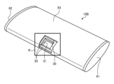
- Fig. 2 is a perspective view showing an example of the configuration of a ceramic-based composite sintered body according to embodiment 2.
- Fig. 2 shows the internal structure of the ceramic-based composite sintered body 10A with a portion of the surface layer removed, and the internal structure of the ceramic-based composite sintered body 10A. The configuration of the ceramic-based composite sintered body 10A will be described with reference to Fig. 2.
- the ceramic-based composite sintered body 10A according to the second embodiment further includes a reinforcing structural member 40 inside the matrix base material 20 in addition to the configuration of the first embodiment.
- the reinforcing structural member 40 is made of a fiber-reinforced composite material.
- inside the matrix base material 20 means the inside of a structure formed by the ceramic-based composite sintered body 10A.
- Examples of the reinforcing structural member 40 are a plate 41, a rod 42, etc.
- the inside of the ceramic-based composite sintered body 10A is not a hollow structure but a solid structure filled with contents, the matrix base material 20 is arranged around the reinforcing structural member 40, and the reinforcing structural member 40 and the matrix base material 20 are configured as an integrated unit.
- the ceramic-based composite sintered body 10A in FIG. 2 has a base 11 and a fin-shaped main body 12 provided on the base 11.
- a plate 41 which is an example of a reinforcing structural member 40, is provided inside the base 11, and a plurality of rods 42, which are an example of a reinforcing structural member 40, are provided inside the main body 12.
- the plurality of rods 42 are integrally configured with the plate 41.
- an integral structure is configured in which only the surface of the matrix base material 20 is covered with the fiber-reinforced composite material layer 30, but in the ceramic-based composite sintered body 10A of the second embodiment, a reinforcing structural member 40 made of a fiber-reinforced composite material is further included inside the matrix base material 20, and is configured to be integrated with the matrix base material 20.
- the ceramic-based composite sintered body 10A can realize a reduction in the weight of the matrix matrix 20, an improvement in the specific elastic modulus, and an improvement in brittleness by including a reinforcing structural member 40 made of a fiber-reinforced composite material inside the matrix matrix 20.
- a reinforcing structural member 40 such as a plate 41 or rod 42 made of a fiber-reinforced composite material inside the matrix matrix 20
- the crack can be prevented from propagating throughout the matrix matrix 20 and causing separation.
- the fiber-reinforced composite material constituting the reinforcing structural member 40 has a smaller specific gravity and a higher elastic modulus than the matrix matrix 20, so that the apparent specific gravity of the matrix matrix 20 containing the reinforcing structural member 40 is reduced and the elastic modulus is improved.
- the reinforcing fibers and matrix materials used in the fiber-reinforced composite layer 30 and the reinforcing structural member 40 are not limited to a unique combination, but can be configured in any combination to suit the conditions of the usage environment.
- the ceramic-based composite sintered body 10A according to the second embodiment further includes a reinforcing structural member 40 made of a fiber-reinforced composite material in the matrix base material 20, and the reinforcing structural member 40 is integrated with the matrix base material 20.
- a reinforcing structural member 40 made of a fiber-reinforced composite material in the matrix base material 20, and the reinforcing structural member 40 is integrated with the matrix base material 20.
- the reinforcing structural member 40 made of a fiber-reinforced composite material has a lower density than the matrix base material 20, the overall density of the ceramic-based composite sintered body 10A can be further reduced compared to the first embodiment.
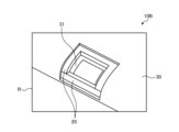
- Fig. 3 is a perspective view showing an example of the configuration of a ceramic-based composite sintered body according to embodiment 3.
- Fig. 4 is an enlarged perspective view of a partial region R of Fig. 3.
- Figs. 3 and 4 also show the internal structure of the ceramic-based composite sintered body 10B with a portion of the surface layer removed. The configuration of the ceramic-based composite sintered body 10B will be described with reference to Figs. 3 and 4.
- the ceramic matrix composite sintered body 10, 10A in the first and second embodiments have a solid structure, but the ceramic matrix composite sintered body 10B in the third embodiment has a hollow structure.
- the ceramic matrix composite sintered body 10B has a hollow elliptical cylindrical structure.
- the ceramic matrix composite sintered body 10B in the third embodiment has a matrix base material 20, a fiber reinforced composite material layer 30 formed on the outer surface of the matrix base material 20, and a fiber reinforced composite material layer 31 formed on the inner surface of the matrix base material 20.
- the fiber reinforced composite material layer 30 is also provided on the inner surface of the elliptical cylindrical matrix base material 20.
- the matrix base material 20 and the fiber reinforced composite material layer 30 on the outer surface, and the matrix base material 20 and the fiber reinforced composite material layer 31 on the inner surface are integrally structured.
- the "inner surface” refers to the surface of the matrix base material 20 or the ceramic matrix composite sintered body 10B that faces the hollow space of the ceramic matrix composite sintered body 10B.
- the matrix base material 20 is a ceramic material, which is brittle and prone to cracking when subjected to localized impact. Therefore, by combining fiber-reinforced composite material layers 30, 31, which have high fracture toughness and are less likely to crack, with the outer and inner surfaces of the matrix base material 20, it becomes possible to mitigate and diffuse the localized impact on the ceramic material. As a result, the strength and fracture toughness of the structure can be further improved.
- the fiber reinforced composite material used for the fiber reinforced composite material layer 31 on the inner surface in the third embodiment can be configured in various combinations, similar to the fiber reinforced composite material layer 30 described in the first and second embodiments.
- the fiber reinforced composite material layers 30, 31 on the outer and inner surfaces of the matrix base material 20 are configured with the same material combination, it is desirable to make the elastic modulus of the fiber reinforced composite material layer 31 on the inner surface lower than that of the fiber reinforced composite material layer 30 on the outer surface and to increase flexibility. This allows the elastic modulus to be changed by adjusting the content ratio of the matrix material and the reinforcing fibers in the fiber reinforced composite material layers 30, 31.
- the elastic modulus of the inner and outer fiber reinforced composite material layers 30, 31 can be controlled by setting the volume content of the reinforcing fibers to 55% in the case of the fiber reinforced composite material layer 30 on the outer surface and the volume content of the reinforcing fibers to 45% in the case of the fiber reinforced composite material layer 31 on the inner surface.
- different fibers may be combined to change the elastic modulus.
- the reinforcing fibers of the fiber-reinforced composite material layer 30 on the outer surface can be high-elasticity pitch-based carbon fibers
- the reinforcing fibers of the fiber-reinforced composite material layer 31 on the inner surface can be PAN-based carbon fibers.
- the reinforcing fibers are not limited to carbon fibers, and one or more materials selected from the group of ceramic fibers, inorganic fibers, glass fibers, and organic fibers can be used.
- the organic fibers are aramid fibers, etc.
- the matrix material can be one or more materials selected from the group of carbon, metal, and ceramics, in addition to resin.
- the modulus of elasticity of the fiber reinforced composite material layer 31 on the inner surface lower than that of the fiber reinforced composite material layer 30 on the outer surface, the brittleness, i.e., the fragility of the ceramic material of the matrix base material 20, can be improved.
- the toughness is improved and the ceramic matrix composite sintered body 10B becomes less likely to crack.
- the characteristics of the fiber reinforced composite material layer 30, specifically the modulus of elasticity are low, the characteristics of the matrix base material 20, specifically the modulus of elasticity, are reduced.
- the matrix base material 20 it is ideal to cover the matrix base material 20 with a fiber reinforced composite material that has a higher modulus of elasticity and excellent toughness, i.e., is less likely to crack, than the matrix base material 20.
- the higher the modulus of elasticity the lower the toughness tends to be, but it is still sufficiently high compared to ceramic materials.
- the fiber-reinforced composite material layer 30 with a high elastic modulus is used for the outer surface, which structurally has a large effect on rigidity
- the fiber-reinforced composite material layer 31 with a higher toughness and lower elastic modulus is used for the inner surface, which structurally has a smaller effect on rigidity. This makes it possible to efficiently improve the elastic modulus and fracture toughness.
- a fiber reinforced composite material layer 30 having a low elastic modulus, i.e., high fracture toughness may be provided on the surface.
- the following three patterns are possible for the combination of the fiber reinforced composite material layer 30 on the outer surface and the fiber reinforced composite material layer 31 on the inner surface.
- the fiber reinforced composite material layer 30 on the outer surface and the fiber reinforced composite material layer 31 on the inner surface are constituted by highly elastic fiber reinforced composite material layers.
- the fiber reinforced composite material layers 30 and 31 are made of a fiber reinforced composite material whose elastic modulus can be controlled by changing the volume content of the reinforcing fibers
- the content of the reinforcing fibers in this fiber reinforced composite material may be made relatively high, for example, higher than the case of (2) below.
- the fiber reinforced composite material layer 30 on the outer surface and the fiber reinforced composite material layer 31 on the inner surface are constituted by low elasticity fiber reinforced composite material layers.
- the fiber reinforced composite material layers 30 and 31 are made of a fiber reinforced composite material whose elastic modulus can be controlled by changing the volume content of the reinforcing fibers
- the content of the reinforcing fibers in this fiber reinforced composite material may be made relatively small, for example, less than that in the above case (1).
- the fiber reinforced composite material layers 30, 31 are made of a fiber reinforced composite material whose elastic modulus can be controlled by changing the volume content of the reinforcing fibers, as described above, the content of reinforcing fibers in the fiber reinforced composite material layer 31 on the inner surface may be made relatively smaller than that in the fiber reinforced composite material layer 30 on the outer surface.
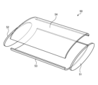
- a hollow ceramic-based composite sintered body 10B having two bottom surface portions 61, 62 and an elliptical cylindrical side surface portion 63 connecting the two bottom surface portions 61, 62 is given as an example, but the ceramic-based composite sintered body 10B may have a structure in which at least one of the two bottom surface portions 61, 62 is missing. Also, instead of an elliptical cylindrical shape, the shape may be a cylindrical shape or a polygonal cylindrical shape.
- the ceramic-based composite sintered body 10B according to the third embodiment has fiber-reinforced composite layers 30, 31 on the outer and inner surfaces, respectively, of a matrix base material 20 having a hollow structure inside.
- a matrix base material 20 having a hollow structure By making the matrix base material 20 hollow, it is possible to achieve a further weight reduction compared to a matrix base material 20 having a solid structure with the same outer shape.
- by covering not only the outer surface but also the inner surface of the matrix base material 20 with fiber-reinforced composite layer 31 it is possible to achieve a ceramic-based composite sintered body 10B that is more resistant to cracking and has a lightweight and highly rigid structure.
- the elastic modulus of the fiber-reinforced composite material layer 31 on the inner surface of the hollow ceramic-based composite sintered body 10B is changed from that of the fiber-reinforced composite material layer 30 on the outer surface. This makes it possible to obtain a molded body with characteristics suited to the conditions of the environment in which it is used.
- Fig. 5 is a flow chart showing an example of the procedure of the method for manufacturing the ceramic-based composite sintered body according to the fourth embodiment.
- the method for manufacturing the ceramic-based composite sintered body 10 includes a raw material mixing step (step S1), a molding step (step S2), a heat treatment step (step S3), a shape processing step (step S4), a silicon infiltration and silicon carbide reaction sintering step (step S5), a composite integration step (step S6), and a finish processing step (step S7).
- step S1 a raw material mixing step
- step S2 a molding step
- step S3 a heat treatment step
- step S4 shape processing step
- step S5 silicon infiltration and silicon carbide reaction sintering step
- step S6 a composite integration step
- step S7 finish processing step
- the raw material mixing process in step S1 is a process for obtaining a mixed raw material containing boron carbide powder, a binder resin as a carbon precursor, and a matrix filler as a silicon carbide precursor.
- a matrix filler is carbon or graphite powder.
- the boron carbide powder, the binder resin, and the matrix filler are uniformly mixed in a determined mixing ratio to generate a mixed raw material. It is desirable that the average particle size of the powder raw material in the mixed raw material has two or more different levels of distribution.
- Table 1 shows an example of the relationship between the average particle size distribution of boron carbide, which is the powder raw material used, and carbon, which is the matrix filler of the silicon carbide precursor.
- the average particle size distribution of the boron carbide raw material powder used is one level, two or more levels of carbon raw material of the matrix filler are used to mix.
- the two levels of average particle size distribution of the carbon raw material of the matrix filler are PD1 (C) and PD2 (C), and PD1 (C) > PD2 (C), as shown in Table 1, it is desirable that the average particle size distribution PD (B 4 C) of boron carbide is between the average particle size distributions PD1 (C) and PD2 (C) of the carbon raw material of the matrix filler at two levels.
- the carbon raw material of the matrix filler having a large average particle size distribution has the effect of widening the dispersion interval of the boron carbide particles and suppressing crowding.
- the carbon raw material of the matrix filler having an average particle size distribution smaller than that of boron carbide fills a part of the gap between the boron carbide particles. These raw materials are fixed with a binder resin to form a molded body in the next step S2, the molding step.
- the average particle size distribution of boron carbide is not limited to one level, and may be two or more levels. If the two levels of average particle size distribution of boron carbide are PD1(B 4 C) and PD2(B 4 C) and PD1(B 4 C)>PD2(B 4 C), it is desirable that the two levels of average particle size distribution of boron carbide PD1(B 4 C ) and PD2(B 4 C) are between the two levels of average particle size distribution of carbon raw material PD1(C) and PD2(C).
- graphite powder is given as an example of the carbon raw material for the matrix filler, but in addition to graphite powder, milled carbon fiber may also be combined.
- the molding process in step S2 is a process in which the mixed raw materials mixed in the raw material mixing process in step S1 are filled into a mold, and the mixed raw materials are heated and pressurized to harden the binder resin and obtain a molded body.
- the heat treatment process in step S3 is a process in which the compact formed in the molding process in step S2 is heat treated in an inert atmosphere to carbonize the binder resin in the compact through pyrolysis, resulting in a fired body. Because the compact does not contain a large amount of binder resin, there is little generation of decomposition gas and little thermal shrinkage due to the heat treatment. For this reason, no special operations such as pressurization during the heat treatment or fixing the shape with a jig are required, but it is also possible to perform the heat treatment under a load using a jig or the like, forcing deformation.
- the shaping process in step S4 is a process in which the sintered body obtained in the heat treatment process in step S3 is machined into the desired shape.
- the sintered body is a matrix material in which the binder resin has been carbonized, and is a porous material that contains voids in which the boron carbide powder and the carbon matrix filler are fixed. This allows the sintered body to be easily shaped using ordinary processing tools.
- the shaped sintered body is referred to as the substrate below.
- the silicon infiltration and silicon carbide reaction sintering process in step S5 is a process in which the substrate obtained in the shape processing process in step S4 is heated together with metal silicon or silicon alloy to infiltrate the metal silicon or silicon alloy into the substrate, react with carbon to form silicon carbide, and sinter the substrate, i.e., boron carbide powder, to obtain a sintered body.
- the substrate is heated together with metal silicon or silicon alloy in a vacuum or inert atmosphere.
- the substrate is infiltrated with molten metal silicon or molten silicon alloy, reacts with the carbon inside the substrate to form silicon carbide, and the boron carbide powder is sintered to obtain a sintered body.
- This sintered body becomes the matrix base material 20.
- the metal silicon or silicon alloy required for the silicon carbide reaction can be continuously supplied from the outside, and the carbon contained inside the substrate reacts with the metal silicon or silicon alloy to form silicon carbide, causing a volume expansion. Therefore, the voids in the substrate are filled with silicon carbide produced by the reaction and the infiltrated metallic silicon or silicon alloy. As a result, the sintered body is substantially void-free and dense. Furthermore, there is almost no shrinkage during sintering before and after sintering, which occurs when sintering conventional ceramic materials. In other words, cracks and deformations during sintering are unlikely to occur. This makes it easy to manufacture uneven-walled structures, hollow structures, or large structures.
- the composite integration process of step S6 combines a fiber-reinforced composite material layer 30 on the surface of the sintered body obtained in the silicon infiltration and silicon carbide reaction sintering process of step S5, and integrates the sintered body with the fiber-reinforced composite material layer 30.
- the composite integration process is a process of laminating a fiber-reinforced composite material layer 30 on the outer surface of the sintered body and integrating the fiber-reinforced composite material layer 30 with the sintered body.
- prepregs in which reinforcing fibers have been pre-impregnated with resin are placed on the surface of the sintered body, and a composite integration process is performed to form a fiber-reinforced composite layer 30 on the surface of the sintered body.
- the resin is a thermosetting resin
- the prepregs are heated as a composite integration process to harden the resin, and a fiber-reinforced composite layer 30 is formed on the surface of the sintered body.
- the resin is a reactive resin
- the resin is treated with a catalyst or the like as a composite integration process to harden the resin at a low temperature. This forms a fiber-reinforced composite layer 30 integrated on the surface of the sintered body.
- the resin is a thermoplastic resin
- the resin is melted as a composite integration process, and the molten resin is brought into close contact with the surface of the sintered body, forming a fiber-reinforced composite layer 30 integrated on the surface of the sintered body.
- the composite integration process of the fiber-reinforced composite material changes the materials and processing conditions used to match the properties required for the matrix material of the fiber-reinforced composite layer 30 depending on the environmental conditions in which the ceramic-based composite sintered body 10 is used.
- the fiber reinforced composite layer 30 can be made of FRP by using resin as the matrix material of the fiber reinforced composite layer 30.
- carbon is used instead of resin for the matrix material of the fiber reinforced composite layer 30.
- the matrix material is made of carbon
- phenolic resin can be used as the matrix raw material of the fiber reinforced composite layer 30 used in the composite integration process.
- heat treatment is performed in an inert atmosphere to carbonize the phenolic resin and change it to carbon. If necessary, resin impregnation and heat treatment may be repeated to fill the matrix material with additional carbon.
- carbon may be filled by a pyrolysis method such as chemical vapor deposition (CVD) or chemical vapor infiltration (CVI).
- CVD chemical vapor deposition
- CVI chemical vapor infiltration
- the matrix material can be made of metal and the fiber-reinforced composite layer 30 can be made of FRM, or the matrix material can be made of ceramics and the fiber-reinforced composite layer 30 can be made of a ceramic-based composite material.
- the fiber-reinforced composite material layer 30 is made of FRM
- a preformed yarn or sheet in which reinforcing fibers are coated with an aluminum alloy is shaped onto the surface, and the preform material is pressed against it while being heated to near the melting point of the aluminum alloy to form and integrate the preform material.
- the metal used in the preform material can be any combination of fiber and metal that can be used as FRM, such as magnesium alloy in addition to aluminum alloy.
- the matrix material of the fiber-reinforced composite layer 30 can be converted to silicon carbide by converting the matrix material into carbon through heat treatment, and then using metal silicon or a silicon alloy, reacting it with the carbon in a vacuum or inert atmosphere to convert it into silicon carbide.
- a coating layer for preventing oxidation and other reactions can be further formed on the surface of the fiber-reinforced composite material layer 30.
- the material and coating method of the coating layer can be selected according to the usage environment conditions. Coating methods include CVD, plasma spraying, ion sputtering, etc.
- the fiber-reinforced composite material layer 30 used in the composite integration process is one or more materials selected from the group consisting of ceramic-based composite materials, FRM, C/C composites, and FRP.
- the reinforcing fibers of the fiber-reinforced composite material layer 30 are one or more materials selected from the group consisting of inorganic fibers, carbon fibers, and organic fibers.
- the finishing process of step S7 is a process for finishing the sintered body, which has been integrated with the fiber-reinforced composite material layer 30 in the compounding and integration process of step S6, into the shape of an article.
- an article made of a ceramic-based composite material sintered body 10 is obtained. Because the sintered body before the final finishing process has a shape close to that of the final article, it can be finished with only a small amount of processing, greatly improving productivity.
- the ceramic-based composite sintered body 10 is manufactured by compounding and integrating the fiber-reinforced composite layer 30 with the surface of the matrix base material 20.
- Embodiment 5 a method for manufacturing the ceramic-based composite sintered body 10A described in the second embodiment will be described.
- Fig. 6 is a flow chart showing an example of the procedure of the method for manufacturing the ceramic-based composite sintered body according to the fifth embodiment. Note that the same steps as those in Fig. 5 of the fourth embodiment are given the same step numbers and the description thereof will be omitted.
- the method for manufacturing the ceramic-based composite sintered body 10A described in the second embodiment is basically the same as the method for manufacturing the ceramic-based composite sintered body 10 described in the fourth embodiment.
- shape processing step S4 in addition to processing the external shape, a new process for embedding a reinforcing structural member 40 inside is added.
- An example of an internal reinforcing structural member 40 is a plate 41, a rod 42, etc. made of a fiber-reinforced composite material. The necessary processing for embedding these reinforcing structural members 40 is performed on the sintered body.
- the reaction in the silicon infiltration and silicon carbide reaction sintering process of step S5, the reaction may be allowed to extend into the embedded reinforcing structural member 40, and silicon carbide reaction sintering may be performed to convert the matrix material of the reinforcing structural member 40 to silicon carbide in the same manner as the sintered body.
- the embedded reinforcing structural member 40 in the silicon infiltration and silicon carbide reaction sintering process of step S5, the embedded reinforcing structural member 40 may be integrated with the sintered body, but may not be converted to silicon carbide.
- the reinforcing structural member 40 may be made of FRP, whose matrix material is plastic resin.
- the fiber reinforced composite material layer 30 integrated in the composite integration process of step S6 has not been subjected to heat treatment such as the silicon infiltration and silicon carbide reaction sintering process of step S5, so the matrix material remains resin.
- the resin is a thermosetting resin
- the fiber reinforced composite material layer 30 is heated only to about a hundred and several tens of degrees Celsius, which is the temperature required to harden the resin. Therefore, the matrix material of the fiber reinforced composite material layer 30 may be carbon instead of resin, making it a C/C composite.
- the manufacturing method of the ceramic-based composite sintered body 10A further includes a heat treatment step (step S11) after the composite integration step of step S6, as shown in FIG. 6.
- step S11 the resin component of the fiber-reinforced composite material layer 30 is carbonized.
- the fiber-reinforced composite material layer 30 becomes a C/C composite.
- the heat treatment step of step S11 is a step that is carried out to control the quality of the matrix material of the fiber-reinforced composite material layer 30 as necessary. This is followed by the finishing processing step of step S7.
- step S11 may be performed after the composite integration process of step S6 in embodiment 4. Furthermore, if necessary, a coating layer may be formed on the surface of the obtained ceramic-based composite sintered body 10A.
- a reinforcing structural member 40 made of a fiber-reinforced composite material is embedded inside the sintered body in the shaping process, and the reinforcing structural member 40 is integrated with the sintered body in the silicon infiltration and silicon carbide reaction sintering processes. This makes it possible to manufacture a ceramic-based composite sintered body 10A having a reinforcing structural member 40 inside, as described in the second embodiment.
- Embodiment 6 a method for manufacturing the ceramic-based composite sintered body 10B described in the third embodiment will be described.
- Fig. 7 is a flow chart showing an example of the procedure of the method for manufacturing the ceramic-based composite sintered body according to the sixth embodiment. Note that the same steps as those in Fig. 5 of the fourth embodiment and Fig. 6 of the fifth embodiment are given the same step numbers, and the description thereof will be omitted.
- the method for manufacturing the ceramic-based composite sintered body 10B described in embodiment 3 is basically the same as the method for manufacturing the ceramic-based composite sintered body 10 described in embodiment 4. However, in the shape processing step of step S4, in addition to processing the outer shape, processing to make the inside a hollow structure is added.
- the substrate can be divided into multiple parts, and then the divided parts can be combined and joined to produce the ceramic matrix composite sintered body 10B.
- FIG. 8 to 11 are perspective views showing an example of the procedure of the method for producing a ceramic-based composite sintered body according to the sixth embodiment.
- the substrate 50 corresponding to the shape of the finished product is appropriately divided into a plurality of parts.
- the substrate 50 is divided into a simple shell structure.
- the elliptical cylindrical substrate 50 is divided into two bottom parts 51, 52 and two side parts 53, 54.
- the silicon infiltration and silicon carbide reaction sintering process of step S5 is performed for each divided part, and then the fiber reinforced composite material layers 30, 31 are placed on the outer and inner surfaces in the composite integration process.
- the fiber reinforced composite material layers 30, 31 are subjected to a composite integration process, whereby the respective parts can be joined.
- the fiber-reinforced composite material layers 30 and 31 When the inner and outer surfaces are covered with the fiber-reinforced composite material layers 30 and 31, if the sintered body is integrated and the hollow interior cannot be accessed, after the silicon infiltration and silicon carbide reaction sintering processes, a fiber-reinforced composite material is placed on the hollow inner surface of each part of the divided sintered body, and a composite integration process is performed to form a fiber-reinforced composite material layer 31 on the part that will become the inner surface.
- each part 51a, 52a, 53a, 54a made of a sintered body with a fiber-reinforced composite material layer 31 formed on the inner surface is assembled, and then a fiber-reinforced composite material is placed on the outer surface and a composite integration process is performed on the fiber-reinforced composite material, thereby joining each part 51a, 52a, 53a, 54a.
- the fiber-reinforced composite material on the outer surface can cover the joints of the matrix base material 20 made of the inner ceramic material and reinforce the joints.
- the parts can be combined and rejoined into one piece using a mixed raw material and a binder. Furthermore, in the silicon infiltration and silicon carbide reaction sintering process, the parts can be integrated by reactive sintering caused by a silicon carbide reaction. At this time, the divided joint surfaces are integrated in the same way as the other parts. The joints between the divided parts are sintered in the same way as the other parts, so they can achieve strength characteristics equivalent to those of the other parts. The final shape is the deciding factor as to which of the above methods to use.
- the manufacturing method of the ceramic-based composite sintered body 10B in FIG. 7 further includes a silicon infiltration and silicon carbide reaction sintering step (step S21) after the heat treatment step of step S11.
- a silicon infiltration and silicon carbide reaction sintering step of step S21 the matrix material of the fiber-reinforced composite layer 30 on the outer surface, which was carbonized in the heat treatment step of step S11, is converted to silicon carbide.
- the matrix material of the fiber-reinforced composite layer 30 becomes a silicon carbide ceramic material, which has improved heat resistance compared to plastic resin. This is followed by the finishing step of step S7.
- the reinforcing fibers and matrix material of the fiber-reinforced composite material layers 30, 31 can be configured in any combination depending on the conditions of the environment in which they are used. Furthermore, the combinations of reinforcing fibers and matrix materials of the fiber-reinforced composite material layers 30, 31 on the outer and inner surfaces do not need to be the same. It is preferable that the fiber-reinforced composite material layer 31 on the inner surface has a lower elastic modulus and higher flexibility than the fiber-reinforced composite material layer 30 on the outer surface.
- the silicon infiltration and silicon carbide reaction sintering process of step S21 may be performed after the heat treatment process of step S11 in embodiment 5.
- the heat treatment process of step S11 and the silicon infiltration and silicon carbide reaction sintering process of step S21 may be performed after the composite integration process of step S6 in embodiment 4.
- a coating layer may be formed on the surface of the obtained ceramic matrix composite sintered body 10B.
- a substrate having a hollow structure inside is formed in the shaping process, and fiber-reinforced composite material layers 30, 31 are integrated with the outer and inner surfaces. This makes it possible to manufacture the ceramic-based composite material sintered body 10B having a hollow structure as described in the third embodiment.
- the ceramic-based composite sintered body 10 is manufactured by the manufacturing method shown in the fourth embodiment.
- boron carbide F150 manufactured by 3M is used as the boron carbide powder of the mixed raw material
- powdered phenolic resin PG-9400 manufactured by Gun-ei Chemical Industry Co., Ltd. is used as the binder resin
- graphite powder manufactured by Fujifilm Wako Pure Chemical Industries Co., Ltd. is used as the filler carbon.
- the compounding ratio of the various raw materials is adjusted to prepare the mixed raw material so that the volume content of boron carbide after sintering is 50% or more, and the volume content of voids in the molded body is 15% or more when molded at a maximum molding pressure of less than 40 MPa in the molding process of step S2.
- step S2 the mixed raw material is filled into a mold, and the maximum molding pressure is less than 40 MPa.
- the temperature is raised to 150°C and then maintained for 90 minutes to harden the binder resin and obtain a molded body.
- the bulk density and voids of the molded body were checked, the bulk density was 1.8 and the volume content of voids was approximately 17%.
- the molded body is heat-treated in an inert atmosphere to carbonize the binder resin and obtain a fired body.
- heating is performed while evacuating the atmosphere inside the furnace with a rotary pump.
- the molded body is not pressurized and is heated to approximately 800°C in a free state, and the temperature is then maintained for 30 minutes, after which it is slowly cooled to obtain a fired body.
- the weight of the fired body after firing is reduced by approximately 5%, and the dimensions are almost unchanged, changing by less than 1%.
- the void volume content of the fired body after firing is approximately 27%. No cracks occur in the fired body.
- a high-temperature vacuum furnace is used to melt metallic silicon and infiltrate it into the sintered body having the shape obtained in the heat treatment process of step S3, and the carbon in the sintered body reacts with the infiltrated metallic silicon to form silicon carbide, which is then reactively sintered to obtain a sintered body.
- the bulk density of the sintered body after sintering is approximately 2.7, and the dimensions of the sintered body after sintering change by approximately 1% compared to the sintered body before sintering. Furthermore, there is no distortion or cracking in the sintered body after sintering.
- Test pieces are cut out from the sintered body obtained after the silicon infiltration and silicon carbide reaction sintering process in step S5, and the main material properties are confirmed.
- the bending strength, fracture toughness, and elastic modulus are confirmed by a four-point bending test according to the Japanese Industrial Standards (JIS), and the bending strength is 280 MPa, the fracture toughness is 4.1 MPa ⁇ m 1/2 , and the elastic modulus is 390 GPa.
- step S6 preparations are made to form a ceramic-based composite sintered body 10 in which the surface of the sintered body obtained in step S5 is covered with a fiber-reinforced composite layer 30.
- a prepreg sheet using pitch-based carbon fiber, Dialead (registered trademark) K63712 manufactured by Mitsubishi Chemical Corporation, and epoxy resin is laminated on the surface of the sintered body as a fiber-reinforced composite material, and the prepreg sheet is heated and cured to form an integrated body.
- the thickness of the matrix base material 20 is set to 2.4 mm
- the thicknesses of the upper and lower surfaces of the surface fiber-reinforced composite layer 30 are each set to 0.3 mm for composite formation.
- the bulk density of the ceramic-based composite sintered body 10 obtained in this manner is 2.45.
- the elastic modulus of the ceramic matrix composite sintered body 10 is 388 GPa, which is almost unchanged from the elastic modulus of the sintered body before compounding. However, because the bulk density changes from 2.7 to 2.45, the specific elastic modulus improves from 144.4 GPa to 158.4 GPa. It is confirmed that the bending strength increases from 280 MPa before compounding to 300 MPa.
- the fracture mode showed brittle fracture before compounding, but after compounding, even if a crack occurs, it does not break all at once, but becomes a tough fracture mode, and it is confirmed that the fracture strain is approximately doubled and the fracture energy is improved by more than three times.
- 10, 10A, 10B ceramic-based composite sintered body, 11: base, 12: main body, 20: matrix base material, 30, 31: fiber-reinforced composite layer, 40: reinforcing structural member, 41: plate, 42: rod, 50: substrate, 51, 52, 61, 62: bottom surface, 53, 54, 63: side surface.
Landscapes
- Chemical & Material Sciences (AREA)
- Engineering & Computer Science (AREA)
- Ceramic Engineering (AREA)
- Manufacturing & Machinery (AREA)
- Materials Engineering (AREA)
- Structural Engineering (AREA)
- Organic Chemistry (AREA)
- Chemical Kinetics & Catalysis (AREA)
- Composite Materials (AREA)
- Ceramic Products (AREA)
Priority Applications (3)
| Application Number | Priority Date | Filing Date | Title |
|---|---|---|---|
| PCT/JP2023/023153 WO2024261970A1 (ja) | 2023-06-22 | 2023-06-22 | セラミックス基複合材料焼結体およびその製造方法 |
| JP2025527354A JPWO2024261970A1 (https=) | 2023-06-22 | 2023-06-22 | |
| CN202380099276.7A CN121358705A (zh) | 2023-06-22 | 2023-06-22 | 陶瓷基复合材料烧结体及其制造方法 |
Applications Claiming Priority (1)
| Application Number | Priority Date | Filing Date | Title |
|---|---|---|---|
| PCT/JP2023/023153 WO2024261970A1 (ja) | 2023-06-22 | 2023-06-22 | セラミックス基複合材料焼結体およびその製造方法 |
Publications (1)
| Publication Number | Publication Date |
|---|---|
| WO2024261970A1 true WO2024261970A1 (ja) | 2024-12-26 |
Family
ID=93935192
Family Applications (1)
| Application Number | Title | Priority Date | Filing Date |
|---|---|---|---|
| PCT/JP2023/023153 Ceased WO2024261970A1 (ja) | 2023-06-22 | 2023-06-22 | セラミックス基複合材料焼結体およびその製造方法 |
Country Status (3)
| Country | Link |
|---|---|
| JP (1) | JPWO2024261970A1 (https=) |
| CN (1) | CN121358705A (https=) |
| WO (1) | WO2024261970A1 (https=) |
Citations (6)
| Publication number | Priority date | Publication date | Assignee | Title |
|---|---|---|---|---|
| JP2002539350A (ja) * | 1999-03-09 | 2002-11-19 | シーメンス アクチエンゲゼルシヤフト | タービン翼およびその製造方法 |
| JP2007513854A (ja) * | 2003-11-25 | 2007-05-31 | エム キューブド テクノロジーズ, インコーポレイテッド | 炭化ホウ素複合体およびその製造方法 |
| JP2010202488A (ja) * | 2008-04-04 | 2010-09-16 | Toto Ltd | 炭化硼素・炭化珪素・シリコン複合材料 |
| WO2011059064A1 (ja) * | 2009-11-13 | 2011-05-19 | 株式会社Ihi | 翼の製造方法 |
| JP2019156687A (ja) * | 2018-03-14 | 2019-09-19 | 三菱重工業株式会社 | タービン翼部材の製造方法 |
| JP7012911B1 (ja) * | 2021-01-26 | 2022-01-28 | 三菱電機株式会社 | 複合セラミックス材料の製造方法 |
-
2023
- 2023-06-22 JP JP2025527354A patent/JPWO2024261970A1/ja active Pending
- 2023-06-22 CN CN202380099276.7A patent/CN121358705A/zh active Pending
- 2023-06-22 WO PCT/JP2023/023153 patent/WO2024261970A1/ja not_active Ceased
Patent Citations (6)
| Publication number | Priority date | Publication date | Assignee | Title |
|---|---|---|---|---|
| JP2002539350A (ja) * | 1999-03-09 | 2002-11-19 | シーメンス アクチエンゲゼルシヤフト | タービン翼およびその製造方法 |
| JP2007513854A (ja) * | 2003-11-25 | 2007-05-31 | エム キューブド テクノロジーズ, インコーポレイテッド | 炭化ホウ素複合体およびその製造方法 |
| JP2010202488A (ja) * | 2008-04-04 | 2010-09-16 | Toto Ltd | 炭化硼素・炭化珪素・シリコン複合材料 |
| WO2011059064A1 (ja) * | 2009-11-13 | 2011-05-19 | 株式会社Ihi | 翼の製造方法 |
| JP2019156687A (ja) * | 2018-03-14 | 2019-09-19 | 三菱重工業株式会社 | タービン翼部材の製造方法 |
| JP7012911B1 (ja) * | 2021-01-26 | 2022-01-28 | 三菱電機株式会社 | 複合セラミックス材料の製造方法 |
Also Published As
| Publication number | Publication date |
|---|---|
| CN121358705A (zh) | 2026-01-16 |
| JPWO2024261970A1 (https=) | 2024-12-26 |
Similar Documents
| Publication | Publication Date | Title |
|---|---|---|
| US6576076B1 (en) | Process for producing fiber-reinforced silicon carbide composites | |
| EP2657207B1 (en) | Method of producing a melt-infiltrated ceramic matrix composite article | |
| CN103387405B (zh) | 一种碳化硅/碳化硅复合材料构件的制备方法 | |
| US20070093587A1 (en) | Silicon carbide precursors and uses thereof | |
| CN108424160A (zh) | 一种短周期碳化硅纤维增强碳化硅复合材料的制备方法 | |
| JP2007535461A (ja) | 炭素繊維強化のセラミックの複合体の製造方法 | |
| CN107428103A (zh) | 用于制造由复合材料制成的涡轮机叶片的方法 | |
| CN106977217A (zh) | 一种高强高韧性碳化硅纤维增强碳化硅陶瓷基复合材料的制备方法 | |
| CN110171976A (zh) | 基于増材制造的SiC基陶瓷零件的制备方法及产品 | |
| US7011785B2 (en) | Process for producing hollow bodies comprising fiber-reinforced ceramic materials | |
| CN112409003A (zh) | 一种杂化基体碳化硅基复合材料及其制备方法 | |
| CN114315394A (zh) | 利用Ti3SiC2三维网络多孔预制体增强SiC陶瓷基复合材料的制备方法 | |
| US20050179152A1 (en) | Process for producing shaped bodies comprising fiber-reinforced ceramic materials | |
| CN110747378A (zh) | 一种Ti3AlC2-Al3Ti双相增强Al基复合材料及其热压制备方法 | |
| JP5068218B2 (ja) | 炭素繊維強化炭化ケイ素複合材料およびその製造方法 | |
| JP7012911B1 (ja) | 複合セラミックス材料の製造方法 | |
| WO2024261970A1 (ja) | セラミックス基複合材料焼結体およびその製造方法 | |
| CN114230347A (zh) | 连续纤维增强ZrC/SiC复合零件的制备方法及产品 | |
| KR20190003901A (ko) | 금속탄화물 필러 함유 섬유강화 세라믹 복합소재 제조방법 | |
| JP7774516B2 (ja) | 複合セラミックス材料の製造方法 | |
| Kulik et al. | High-temperature permanent joints of carbon fiber-reinforced ceramic-matrix composites with similar and other carbonaceous materials | |
| CN110453104A (zh) | 一种钛基SiC-Ti混杂梯度材料及其制备方法 | |
| CN116462525A (zh) | 一种连续碳纤维增强超高温陶瓷基复合材料及其制备方法 | |
| KR102176183B1 (ko) | Pva 및 peg가 함유된 텅스텐 섬유강화 텅스텐 기지 복합재료 | |
| Minei | Manufacturing and Testing of Ceramic Based Hybrid Composites with Various Fibers, Matrix Systems, and Processing Conditions. |
Legal Events
| Date | Code | Title | Description |
|---|---|---|---|
| 121 | Ep: the epo has been informed by wipo that ep was designated in this application |
Ref document number: 23942403 Country of ref document: EP Kind code of ref document: A1 |
|
| WWE | Wipo information: entry into national phase |
Ref document number: 2025527354 Country of ref document: JP |
|
| WWE | Wipo information: entry into national phase |
Ref document number: 2501008631 Country of ref document: TH |
|
| NENP | Non-entry into the national phase |
Ref country code: DE |