WO2024261879A1 - 推定装置、学習装置、推定方法及び推定プログラム - Google Patents
推定装置、学習装置、推定方法及び推定プログラム Download PDFInfo
- Publication number
- WO2024261879A1 WO2024261879A1 PCT/JP2023/022805 JP2023022805W WO2024261879A1 WO 2024261879 A1 WO2024261879 A1 WO 2024261879A1 JP 2023022805 W JP2023022805 W JP 2023022805W WO 2024261879 A1 WO2024261879 A1 WO 2024261879A1
- Authority
- WO
- WIPO (PCT)
- Prior art keywords
- work
- unit
- image
- joint
- time
- Prior art date
- Legal status (The legal status is an assumption and is not a legal conclusion. Google has not performed a legal analysis and makes no representation as to the accuracy of the status listed.)
- Ceased
Links
Images







Classifications
-
- G—PHYSICS
- G06—COMPUTING OR CALCULATING; COUNTING
- G06T—IMAGE DATA PROCESSING OR GENERATION, IN GENERAL
- G06T7/00—Image analysis
-
- G—PHYSICS
- G06—COMPUTING OR CALCULATING; COUNTING
- G06T—IMAGE DATA PROCESSING OR GENERATION, IN GENERAL
- G06T7/00—Image analysis
- G06T7/20—Analysis of motion
Definitions
- the present disclosure relates to a technique for estimating an elemental work being performed by a worker.
- An elemental task is an action that can be recognized as a single unit, and is a component of a task.
- a task is composed of a combination of multiple elemental tasks. For example, the elemental task "Placing the cover in the installation position” and the elemental task “Screwing the cover in place” are combined to form one task, "Attach the cover.”
- Japanese Patent Laid-Open No. 2003-233693 discloses a technique for capturing an image of a person's behavior and estimating the person's behavior from the captured image.
- time-series position data of human body parts obtained from a video is classified into multiple position data.
- each position data is analyzed, and a motion sequence (movement, change, rest, etc.) is generated from the analysis result.
- a neural network that handles time-series data such as an RNN (Recurrent Neural Network)
- analyzes the motion sequence In the technology of Patent Document 1, a memory neural network processes the analysis result.
- An operation includes element tasks with various attributes, such as element tasks that take a short time to perform, element tasks that take a long time to perform, element tasks that occur infrequently, and element tasks that occur frequently.
- element tasks with various attributes such as element tasks that take a short time to perform, element tasks that take a long time to perform, element tasks that occur infrequently, and element tasks that occur frequently.
- position data which is time-series data divided into short intervals
- a neural network that handles time-series data.
- a category is a label that indicates the type of element work that a worker is performing and a label that indicates a time period during which the worker is not performing any element work.
- Issue (2) Furthermore, even if a new category of elemental work is created in order to improve the balance of the amount of time-series data between categories, additional data collection is required for the new category. Issue (3) In addition, even if the time series data of an element task that takes a long time to perform is divided into multiple time series data for short periods of time, each time series data only represents a part of the element task. This increases the variability of the time series data even within the same category, making it difficult to learn to generate a model that estimates the element task. Issue (4) Due to the above problems (1) to (3), when a task includes multiple elemental tasks whose attributes are not uniform, such as having different execution times and/or occurrence frequencies, it is not possible to accurately estimate the elemental tasks performed by a worker.
- One of the main objectives of this disclosure is to solve the problems described above. More specifically, the main objective of this disclosure is to enable accurate estimation of the elemental work performed by a worker, even when the work involves multiple elemental work tasks, each of which has non-uniform attributes.
- the estimation device comprises: a time division unit that divides a work engagement time into a work performance time zone during which the worker is performing any one of the plurality of elemental tasks and a non-work time zone during which the worker is not performing any one of the plurality of elemental tasks, using at least one of a result of a displacement amount determination that determines an amount of displacement of the hand of a worker during a work engagement time that is a time during which the worker is engaged in a task including a plurality of elemental tasks, each of which has non-uniform attributes, while the worker is engaged in the task, a result of a tool gripping state determination that determines a state in which the tool is gripped by the hand of the worker during the work engagement time, and a result of an appearance state determination that determines an appearance state of the hand of the worker in an image captured during the work engagement time;
- the system further includes an estimation unit that estimates an elemental work being performed by the worker during the work performance time period based on a partial image that is a portion of
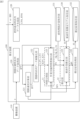
- FIG. 2 is a diagram showing an overview of an example of a functional configuration of an estimation device according to the first embodiment.
- 11 is a diagram showing an example of a time division process using only the determination result of the appearance situation determination in the first embodiment.
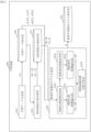
- FIG. 2 is a diagram showing an example of a detailed functional configuration of the estimation device according to the first embodiment.
- 4 is a diagram showing an example of the internal configuration of a task execution time zone detection unit and an element task estimation unit according to the first embodiment;
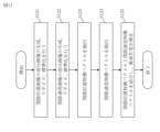
- FIG. 4 is a flowchart showing an example of the operation of the estimation device according to the first embodiment.
- 10 is a flowchart showing an example of the operation of an operation execution time period detection unit according to the first embodiment.
- 10 is a flowchart showing an example of the operation of an element work estimation unit according to the first embodiment.
- FIG. 13 is a diagram showing an example of the functional configuration of a learning device according to a second embodiment.
- FIG. 13 is a diagram showing an example of the internal configuration of an element work estimation model generation unit according to the second embodiment.
- FIG. 13 is a flowchart showing an example of the operation of the learning device according to the second embodiment.
- FIG. 13 is a diagram showing an example of the functional configuration of a learning device according to a third embodiment.
- FIG. 13 is a diagram showing an example of the internal configuration of an operation execution time period detection model generation unit according to the third embodiment.
- 13 is a flowchart showing an example of the operation of the learning device according to the third embodiment.
- FIG. 13 is a diagram showing an example of a functional configuration of an estimation device according to a fourth embodiment.
- FIG. 13 is a diagram showing an example of the functional configuration of a learning device according to a fifth embodiment.
- FIG. 1 is a diagram showing an overview of an imaging process according to a first embodiment
- 4 is a diagram showing an overview of an operation execution time period detection process, an element operation estimation process, and an estimation result process according to the first embodiment.
- FIG. FIG. 1 is a diagram showing an example of a hardware configuration of an estimation device according to first and fourth embodiments.
- FIG. 13 is a diagram showing an example of the hardware configuration of a learning device according to the second, third and fifth embodiments.
- Embodiment 1 This disclosure describes a method for accurately estimating the task elements being performed by a worker.
- An "operator” is a person (worker) or robot (working robot) engaged in work.
- an "operator's hand” includes a human (worker's) hand and a component part of a robot (working robot) that has the same function and/or role as a human hand.
- an "operator's hand” includes at least one of the palm, back of the hand, wrist, and fingers of a human (worker) and a component part of a robot (working robot) that corresponds to any one of the palm, back of the hand, wrist, and fingers.
- a person (worker) is engaged in machine adjustment work.
- ***Configuration Description*** 1 shows an overview of an example of a functional configuration of an estimation device 100 according to the present embodiment.
- the estimation device 100 operates in an estimation phase.
- the estimation device 100 is connected to an imaging device 110 .
- the image capture device 110 captures an image of the worker's hands during work engagement time.
- Work engagement time is the time during which the worker is engaged in work.
- the imaging device 110 outputs an image of the worker's hands obtained by imaging to the estimation device 100.
- the imaging device 110 is, for example, worn on the head of a worker and captures a first-person perspective image. In this embodiment, the imaging device 110 is assumed to be worn on the head of the worker. However, the imaging device 110 does not have to be worn on the head of the worker as long as it can capture an image of the worker's hands.
- the image capturing device 110 may not only be a device that captures normal color images, but may also include a sensor having another modality, such as a depth sensor.
- a depth sensor is capable of capturing images at a wider angle.
- the estimation device 100 may determine that the hand is present as long as the hand is present within the imaging range of the depth sensor.
- the estimation device 100 includes a time division unit 11 and an estimation unit 12 . As described below, the estimation device 100 has a detailed functional configuration shown in FIGS. 7 and 8. However, in FIG. 1, the functional configuration of the estimation device 100 is shown in a simplified manner for ease of understanding. Before describing the detailed configuration of the estimation device 100 shown in FIGS. 7 and 8, the functional configuration of the simplified estimation device 100 shown in FIG. 1 will be described.
- the time division unit 11 divides the work time into a work execution time period and a non-work time period using at least one of the results of the displacement amount determination, the results of the tool holding status determination, and the results of the appearance status determination.
- the displacement amount determination is a process of determining the amount of displacement of the worker's hand.
- the tool holding state determination is a process for determining the state in which a tool is held by a worker's hand.
- the tool is a tool used in machine adjustment work.
- the appearance status determination is a determination process for determining the appearance status of the worker's hands in the video captured during the work engagement time.
- a work performance time period is a time period during which a worker performs one of a plurality of elemental works.
- a non-working time period is a time period during which the worker is not performing any of the elemental works among a plurality of elemental works.
- the process performed by the time division unit 11 corresponds to a time division process.
- the estimation unit 12 estimates the elemental work being performed by the worker during the work performance time period based on a partial image that is a portion of the image captured during the work performance time period that is captured during the work performance time period. Specifically, the estimation unit 12 estimates the element work performed by the worker during the work performance time period using a trained model generated by training.
- FIG. 2 shows an example in which the time dividing unit 11 divides the work engagement time into a work execution time period and a non-work time period using only the result of the displacement amount determination.
- FIG. 3 shows an example in which the time dividing unit 11 divides the work engagement time into a work execution time period and a non-work time period using only the result of the tool gripping state determination.
- FIG. 4 shows an example in which the time dividing unit 11 divides the work engagement time into a work performance time period and a non-work time period using only the determination result of the appearance status determination.
- FIG. 5 shows an example in which the time division unit 11 divides work time into a work execution time period and a non-work time period using the results of the displacement amount determination, the results of the tool holding status determination, and the results of the appearance status determination.
- the result of the displacement amount determination in Fig. 2 indicates the displacement amount of the worker's hand during the work engagement time.
- the result of the displacement amount determination is shown in a graph.
- the time division unit 11 acquires time series data of the joints of the hand derived from an image of the worker's hand captured by the imaging device 110. Then, the amount of displacement of the hand per unit time is determined from the time series data of the joints of the hand.
- the estimation device 100 is assumed to include a mechanism for converting an image of the worker's hand into time-series data of the hand joints.
- the time division unit 11 designates a time period during which the amount of hand displacement per unit time is less than the threshold as a task execution time period, while the time division unit 11 designates a time period during which the amount of hand displacement per unit time is equal to or greater than the threshold as a non-task time period.
- the time period when the amount of hand displacement is large is thought to be a non-work time period.
- the result of the tool holding state determination in FIG. 3 indicates whether or not a tool is being held.
- the estimation device 100 is assumed to include a mechanism for identifying the tool held by the worker's hand.
- the worker was holding a wrench.
- the worker was holding a screwdriver.
- the worker was not holding any tools.
- the worker was holding a steel ruler.
- the time division unit 11 designates a time period during which the worker's hands are holding a tool as a work performance time period, while the time division unit 11 designates a time period during which the worker's hands are not holding any tool as a non-work time period.
- the time division unit 11 designates each time period during which the worker's hand holds a different type of tool as a different work performance time period.
- the time division unit 11 designates a time period during which the worker's hand holds a wrench and a time period during which the worker's hand holds a screwdriver as different work performance time periods.
- the determination result of the appearance status determination in FIG. 4 indicates whether or not the worker's hands are appearing in the image captured by the imaging device 110.
- the time division unit 11 can determine whether or not the worker's hand is present by analyzing the image captured by the imaging device 110 or the time-series data of the hand joints. In the example of Figure 4, first the worker's hand appears in the image. Then the worker's hand disappears from the image. After that, the worker's hand appears in the image again.
- the time division unit 11 designates a time period during which the worker's hands appear in the video as a work performance time period, while the time division unit 11 designates a time period during which the worker's hands do not appear in the video as a non-work time period.
- FIG. 5 shows an example in which the time dividing unit 11 divides the work engagement time into a work execution time period and a non-work time period using three determination results.
- the time division unit 11 designates that time period as a non-work time period, regardless of whether the worker's hand is holding a tool or not and regardless of whether the worker's hand appears in the image or not.
- the time division unit 11 designates the time period as a work performance time period regardless of whether the worker's hand is holding a tool or not.
- the time division unit 11 designates the time period as a non-work time period regardless of whether the worker's hand is holding a tool or not. In this way, when two or more of the judgment results of the displacement amount judgment, the judgment result of the tool holding status judgment, and the judgment result of the appearance status judgment are used, the user of the estimation device 100 defines in advance the application criteria for determining the priority order in which the two or more judgment results are to be applied.
- the estimation unit 12 applies the time series data of the hand joints derived from the partial video captured during the work performance time period to the learned model, and estimates the elemental work performed by the worker during the work performance time period.
- the trained model used by the estimation unit 12 is generated by a training device 200 described later.
- the estimation device 100 performs a two-stage process of detecting a task execution time period by the time dividing unit 11 and estimating an element task using a partial video by the estimation unit 12. Therefore, the estimating device 100 according to the present embodiment can accurately estimate the work elements performed by the workers.
- the estimation device 100 is a computer having a hardware configuration exemplified in FIG. As shown in FIG. 22, the estimation device 100 includes, as hardware, a processor 801, a main memory device 802, an auxiliary memory device 803, and a communication device 804.
- the functions of the time division unit 11 and the estimation unit 12 shown in FIG. 1, and further the components shown in FIGS. 7 and 8, are realized by, for example, a program.
- the auxiliary storage device 803 stores programs that realize the functions of these components. These programs are loaded from the auxiliary storage device 803 to the main storage device 802. Then, the processor 801 executes these programs to perform the operations of these components.
- the operating procedure of the estimation device 100 corresponds to an estimation method. Furthermore, the program that realizes the operation of the estimation device 100 corresponds to an estimation program.
- FIG. 7 shows an example of a detailed functional configuration of the estimation device 100 shown in FIG.
- the estimation device 100 includes a joint position time series data acquisition unit 120, a joint velocity calculation unit 121, a joint time series data imaging unit 122, an task performance time zone detection unit 123, an element work estimation unit 124, an estimation result processing unit 125, an element work estimation model storage unit 130, a pre-processing statistics storage unit 131, and an estimation result storage unit 132.
- the task execution time zone detection unit 123 corresponds to the time division unit 11 shown in Fig. 1.
- the element task estimation unit 124 corresponds to the estimation unit 12 shown in Fig. 1.
- the joint position time-series data acquisition unit 120 acquires an image V obtained by capturing an image of the worker's hand from the imaging device 110.
- the image V is an image captured during the work engagement time in the estimation phase.
- the image V includes frames in which the worker's hand is captured and frames in which the worker's hand is not captured.
- the joint position time series data acquisition unit 120 generates joint position time series data HPT from the video V.
- the joint position time series data HPT is data indicating the spatial position coordinates of each joint of the hand.
- the joint position time-series data acquisition unit 120 generates the joint position time-series data HPT, for example, by using an existing hand tracking model that estimates the positions of the hand joints.
- the joint position time series data acquisition unit 120 generates the right hand joint position time series data HPT and the left hand joint position time series data HPT. Note that, hereinafter, when simply referring to the joint position time series data HPT, it refers to both the right hand joint position time series data HPT and the left hand joint position time series data HPT.
- the joint position time series data acquisition unit 120 inserts a value that enables determination that no hands appear into the joint position time series data HPT. Then, the joint position time series data acquiring unit 120 outputs the joint position time series data HPT to the joint velocity calculating unit 121 and the joint time series data imaging unit 122. In addition, the joint position time series data acquiring unit 120 may output the joint position time series data HPT to the task execution time zone detecting unit 123.
- the joint velocity calculation unit 121 acquires the joint position time series data HPT from the joint position time series data acquisition unit 120 . Then, the joint velocity calculation unit 121 calculates the difference (velocity) in the time direction for each joint of the joint position time series data HPT. Then, the joint velocity calculation unit 121 outputs the joint velocity time series data HVT indicating the calculation result to the joint time series data imaging unit 122. The joint velocity calculation unit 121 may output the joint velocity time series data HVT to the task execution time zone detection unit 123. The joint velocity calculation unit 121 generates the joint velocity time series data HVT of the right hand and the joint velocity time series data HVT of the left hand. Note that, hereinafter, when simply referring to the joint velocity time series data HVT, it refers to both the joint velocity time series data HVT of the right hand and the joint velocity time series data HVT of the left hand.
- the joint time series data imaging unit 122 acquires the joint position time series data HPT from the joint position time series data acquisition unit 120. In addition, the joint time series data imaging unit 122 acquires the joint velocity time series data HVT from the joint velocity calculation unit 121. The joint time-series data imaging unit 122 images the joint position time-series data HPT to generate a left wrist joint position image LJPI and a right wrist joint position image RJPI. The joint time-series data imaging unit 122 also images the joint velocity time-series data HVT to generate a left wrist joint velocity image LJVI and a right wrist joint velocity image RJVI.
- the joint time-series data visualization unit 122 outputs the left hand joint position image LJPI, the right hand joint position image RJPI, the left hand joint velocity image LJVI, and the right hand joint velocity image RJVI to the task execution time zone detection unit 123.
- the joint position time series data HPT and imaging of the joint velocity time series data HVT by the joint time series data imaging unit 122 will be described.
- 20 shows an overview of the imaging process of the joint time-series data imaging unit 122.
- Imaging refers to generating time-series data of the three-dimensional coordinates of a joint by regarding the x, y, and z values of the three-dimensional coordinates as R, G, and B of an image.
- the joint position time-series data HPT for each time t includes spatial position coordinates of J (J ⁇ 2) joints.
- the coordinate axes C are the x-axis, the y-axis, and the z-axis.
- the joint time-series data imaging unit 122 generates a tensor having elements of each joint j and each axis coordinate value c of the J joints in the left hand joint position time-series data HPT, for example. Then, the joint time-series data imaging unit 122 combines the tensors in the time direction to generate a left hand joint position image LJPI. The joint time-series data imaging unit 122 also generates the right wrist joint position image RJPI in a similar procedure. Further, the joint time-series data imaging unit 122 generates a left hand joint velocity image LJVI from the left hand joint velocity time-series data HVT in a similar procedure. Further, the joint time-series data imaging unit 122 generates a right hand joint velocity image RJVI from the right hand joint velocity time-series data HVT in a similar procedure.
- the gripping tool time-series data generator 126 acquires the video V or the sensor information RRS.
- the video V is an image captured by the imaging device 110.
- the gripping tool time-series data generation unit 126 may acquire the video V from the joint position time-series data acquisition unit 120, or may acquire the video V from the imaging device 110 independently of the joint position time-series data acquisition unit 120.
- the sensor information RRS is information that indicates whether the worker is holding a tool or not, and if the worker is holding a tool, the sensor information RRS indicates the type of tool that the worker is holding.
- the tag-type wireless communication sensor when a tag-type wireless communication sensor such as an RFID is attached to the hand of a worker, the tag-type wireless communication sensor receives a signal transmitted from the tool held by the worker. The tag-type wireless communication sensor then determines the type of tool held by the worker based on the received signal. Furthermore, when the tag-type wireless communication sensor does not receive a signal, it determines that the worker is not holding a tool. The tag-type wireless communication sensor outputs the determination result to the held tool time-series data generator 126 as sensor information RRS.
- sensor information RRS sensor information
- the gripped tool time-series data generator 126 uses the video V or the sensor information RRS to identify whether the worker's hand is gripping a tool. If the worker's hand is gripping a tool, the gripped tool time-series data generator 126 identifies the type of tool the worker's hand is gripping. When acquiring the video V, the held tool time-series data generator 126 identifies from each frame of the video V whether the worker is holding a tool and the type of tool, for example, by using a known object detection model. When acquiring the sensor information RRS, the held tool time-series data generator 126 analyzes the sensor information RRS to identify whether or not the worker is holding a tool and the type of tool.
- the gripped tool time-series data generating unit 126 outputs the left hand gripped tool data LTO1 and the right hand gripped tool data RTO1 indicating the identification results to the task execution time zone detecting unit 123.
- the left hand held tool data LTO1 is data that indicates in chronological order whether or not the worker's left hand is holding a tool and the type of tool being held. In other words, by analyzing the left hand held tool data LTO1, it is possible to identify the time period during which the worker's left hand is holding a tool and the time period during which the worker's left hand is not holding a tool.
- the left hand held tool data LTO1 is data that indicates in a time series whether the worker's right hand is holding a tool and the type of tool being held.
- the right hand held tool data RTO1 it is possible to identify in a time series the time periods when the worker's right hand is holding a tool and the time periods when the worker's right hand is not holding a tool.
- the right hand held tool data RTO1 it is possible to identify the type of tool being held by the worker's right hand during the time periods when the worker's right hand is holding a tool.
- the task execution time zone detection unit 123 acquires a left wrist joint position image LJPI, a left wrist joint velocity image LJVI, a right wrist joint position image RJPI, and a right wrist joint velocity image RJVI from the joint time-series data imaging unit 122. Furthermore, the task execution time zone detection unit 123 acquires the left hand gripped tool data LTO1 and the right hand gripped tool data RTO1 from the gripped tool time series data generation unit 126.
- the task performance time zone detection unit 123 analyzes the left hand joint position image LJPI and/or the left hand joint velocity image LJVI. Then, the task performance time zone detection unit 123 generates a left hand appearance time zone set LS, which is a set of time zones in which the left hand appears in the video. Similarly, the task performance time zone detection unit 123 analyzes the right hand joint position image RJPI and/or the right hand joint velocity image RJVI. Then, the task performance time zone detection unit 123 generates a right hand appearance time zone set RS which is a set of time zones in which the right hand appears in the image. In this manner, the operation execution time zone detection unit 123 performs the occurrence status determination shown in FIG.
- the task performance time zone detection unit 123 may determine the appearance status using the joint position time series data HPT. Furthermore, when the task performance time zone detection unit 123 acquires the joint velocity time series data HVT from the joint velocity calculation unit 121, the task performance time zone detection unit 123 may determine the appearance status using the joint velocity time series data HVT.
- the work performance time zone detection unit 123 extracts, in chronological order, time zones during which a tool is being held and time zones during which a tool is not being held for each of the left and right hands based on the left hand held tool data LTO1 and the right hand held tool data RTO1. Furthermore, when the type of tool held by the worker is changing, the work performance time zone detection unit 123 extracts different time zones for each type of tool.
- the extraction result of the work execution time zone detection unit 123 is referred to as the tool gripping state determination result TS.
- the tool holding status determination result TS indicates, in chronological order, the time periods when the worker is holding the tool and the time periods when the worker is not holding the tool.
- the tool holding status determination result TS also associates the time periods when the worker is holding the tool with the type of tool held by the worker in that time period. In this manner, the task execution time zone detection unit 123 performs the tool holding state determination shown in FIG.
- the task execution time zone detection unit 123 analyzes the left hand joint position image LJPI and/or the left hand joint velocity image LJVI to calculate the amount of displacement of the left hand per unit time. Similarly, the task execution time zone detection unit 123 analyzes the right hand joint position image RJPI and/or the right hand joint velocity image RJVI to calculate the amount of displacement of the right hand per unit time. In this manner, the work execution time zone detection unit 123 performs the displacement amount determination shown in FIG. Furthermore, when the task performance time zone detection unit 123 acquires the joint position time series data HPT from the joint position time series data acquisition unit 120, the task performance time zone detection unit 123 may determine the amount of displacement using the joint position time series data HPT. When the task performance time zone detection unit 123 acquires the joint velocity time series data HVT from the joint velocity calculation unit 121, the task performance time zone detection unit 123 may determine the amount of displacement using the joint velocity time series data HVT.
- the work performance time zone detection unit 123 divides the work performance time zone into a work performance time zone and a non-work time zone based on at least one of the determination results. Specifically, the work performance time zone detection unit 123 identifies the start time and end time of the work performance time zone, and identifies the start time and end time of the non-work time zone, and divides the work performance time zone into a work performance time zone and a non-work time zone. In addition, when the work performance time zone detection unit 123 divides the work engagement time into a work performance time zone and a non-work time zone using only the results of the appearance status determination, it does not need to perform the tool gripping status determination and the displacement amount determination.
- the work performance time zone detection unit 123 divides the work engagement time into a work performance time zone and a non-work time zone using only the results of the tool holding status determination, it does not need to perform the appearance status determination and the displacement amount determination.
- the work performance time zone detection unit 123 divides the work engagement time into work performance time zones and non-work time zones using only the results of the displacement amount determination, it does not need to perform appearance status determination and tool grasping status determination.
- the work implementation time zone detection unit 123 outputs a work implementation time zone set FS, which is a set of work implementation time zones, to the element work estimation unit 124.
- the work implementation time zone set FS indicates the start time and end time of the work implementation time zone for each work implementation time zone.
- the work implementation time zone detection unit 123 outputs a non-work time zone set NFS, which is a set of non-work time zones, to the estimation result processing unit 125.
- the non-work time zone set NFS indicates the start time and end time of each non-work time zone.
- the element work estimation unit 124 acquires the work performance time zone set FS from the work performance time zone detection unit 123 . Furthermore, the element work estimation unit 124 acquires a left wrist joint position image LJPI, a left wrist joint velocity image LJVI, a right wrist joint position image RJPI, and a right wrist joint velocity image RJVI from the joint time-series data imaging unit 122 . Furthermore, the element work estimation unit 124 acquires the element work estimation model M from the element work estimation model storage unit 130. The element work estimation model M corresponds to the trained model shown in FIG. Furthermore, the element work estimation unit 124 acquires preprocessing statistics from the estimation result storage unit 132. Specifically, the element work estimation unit 124 acquires, as the preprocessing statistics, a joint position luminance average value PM, a joint position luminance standard deviation PS, a joint velocity luminance average value VM, and a joint velocity luminance standard deviation VS.
- the joint position luminance average value PM is the average luminance value of the joint position image for learning obtained by the learning device 200 described later.
- the joint position luminance standard deviation PS is the standard deviation of the luminance of the joint position image for training obtained by the training device 200.
- the brightness is the coordinate value for each coordinate axis C included in the joint position image.
- the learning joint position images are joint position images used in the learning phase, and correspond to the left hand joint position image LJPI and right hand joint position image RJPI described above.
- the average joint position luminance value PM includes the average left hand joint position luminance value LPM and the average right hand joint position luminance value RPM.
- the average left hand joint position luminance value LPM is the average value obtained from the left hand joint position label image sLJPI, which is a learning left hand joint position image.
- the average right hand joint position luminance value RPM is the average value obtained from the right hand joint position label image sRJPI, which is a learning right hand joint position image.
- the left hand joint position luminance average value LPM is obtained for each coordinate axis C. Therefore, strictly speaking, the left hand joint position luminance average value LPM is expressed as the left hand joint position luminance average value LPM(C).
- the right hand joint position luminance average value RPM is also found for each coordinate axis C. Therefore, strictly speaking, the right hand joint position luminance average value RPM is expressed as the right hand joint position luminance average value RPM(C). Unless otherwise specified precisely, the left wrist joint position luminance average value LPM and the right wrist joint position luminance average value RPM will be collectively referred to as the joint position luminance average value PM. Note that, instead of using the average luminance value for the left hand and the average luminance value for the right hand as described above, the average luminance value for both the left hand and the right hand may be used. In the following, an example in which the average luminance value for the left hand and the average luminance value for the right hand are used will be described, but the following description also applies to the case in which the average luminance value for both the left hand and the right hand is used.
- the joint position luminance standard deviation PS also includes a left hand joint position luminance standard deviation LPS and a right hand joint position luminance standard deviation RPS.
- the left hand joint position luminance standard deviation LPS is a standard deviation obtained from a left hand joint position label image sLJPI, which is a left hand joint position image for learning.
- the right hand joint position luminance standard deviation RPS is a standard deviation obtained from a right hand joint position label image sRJPI, which is a right hand joint position image for learning.
- the left hand joint position luminance standard deviation LPS is also found for each coordinate axis C. Therefore, in a strict sense, the left hand joint position luminance standard deviation LPS is expressed as the left hand joint position luminance standard deviation LPS(C).
- the right hand joint position luminance standard deviation RPS is also found for each coordinate axis C. Therefore, in a strict sense, the right hand joint position luminance standard deviation RPS is expressed as the right hand joint position luminance standard deviation RPS(C). Unless a strict notation is required, the left hand joint position luminance standard deviation LPS and the right hand joint position luminance standard deviation RPS will be collectively referred to as the joint position luminance standard deviation PS. Note that, instead of using the luminance standard deviation for the left hand and the luminance standard deviation for the right hand as described above, the luminance standard deviation over both the left hand and the right hand may be used. In the following, an example in which the luminance standard deviation for the left hand and the luminance standard deviation for the right hand are used will be described, but the following description also applies to the case in which the luminance standard deviation over both the left hand and the right hand is used.
- the joint velocity luminance average value VM is the average luminance value of the training joint velocity image obtained by the training device 200.
- the joint velocity luminance standard deviation VS is the standard deviation of the luminance of the training joint velocity image obtained by the training device 200.
- the learning joint velocity images are joint velocity images used in the learning phase, and correspond to the left wrist joint velocity image LJVI and right wrist joint velocity image RJVI described above.
- the joint velocity brightness average value VM also includes a left wrist joint velocity brightness average value LVM and a right wrist joint velocity brightness average value RVM.
- the left wrist joint velocity brightness average value LVM is an average value obtained from a left wrist joint velocity label image sLJVI, which is a left wrist joint velocity image for learning.
- the right wrist joint velocity brightness average value RVM is an average value obtained from a right wrist joint velocity label image sRJVI, which is a right wrist joint velocity image for learning.
- the left wrist joint velocity luminance average value LVM is also obtained for each coordinate axis C. Therefore, if the left wrist joint velocity luminance average value LVM is expressed strictly, it is expressed as the left wrist joint velocity luminance average value LVM(C).
- the right hand joint velocity brightness average value RVM is also calculated for each coordinate axis C. Therefore, in a strict sense, the right hand joint velocity brightness average value RVM is expressed as the right hand joint velocity brightness average value RVM(C). Unless a strict notation is required, the left wrist joint velocity brightness average value LVM and the right wrist joint velocity brightness average value RVM will be collectively referred to as the joint velocity brightness average value VM. Note that, instead of using the average luminance value for the left hand and the average luminance value for the right hand as described above, the average luminance value for both the left hand and the right hand may be used. In the following, an example in which the average luminance value for the left hand and the average luminance value for the right hand are used will be described, but the following description also applies to the case in which the average luminance value for both the left hand and the right hand is used.
- the joint velocity brightness standard deviation VS also includes a left hand joint velocity brightness standard deviation LVS and a right hand joint velocity brightness standard deviation RVS.
- the left hand joint velocity brightness standard deviation LVS is a standard deviation obtained from a left hand joint velocity label image sLJVI, which is a left hand joint velocity image for learning.
- the right hand joint velocity brightness standard deviation RVS is a standard deviation obtained from a right hand joint velocity label image sRJVI, which is a right hand joint velocity image for learning.
- the left wrist joint velocity luminance standard deviation LVS is also calculated for each coordinate axis C. Therefore, the left wrist joint velocity luminance standard deviation LVS can be expressed strictly as the left wrist joint velocity luminance standard deviation LVS(C).
- the right hand joint velocity luminance standard deviation RVS is also calculated for each coordinate axis C. Therefore, in a strict sense, the right hand joint velocity luminance standard deviation RVS is expressed as the right hand joint velocity luminance standard deviation RVS(C). Unless a strict notation is required, the left wrist joint velocity luminance standard deviation LVS and the right wrist joint velocity luminance standard deviation RVS will be collectively referred to as the joint velocity luminance standard deviation VS. Note that, instead of using the luminance standard deviation for the left hand and the luminance standard deviation for the right hand as described above, the luminance standard deviation over both the left hand and the right hand may be used. In the following, an example in which the luminance standard deviation for the left hand and the luminance standard deviation for the right hand are used will be described, but the following description also applies to the case in which the luminance standard deviation over both the left hand and the right hand is used.
- the element work estimation unit 124 extracts partial images constituting a partial video captured during a work performance time period from each of the left hand joint position image LJPI, the left hand joint velocity image LJVI, the right hand joint position image RJPI, and the right hand joint velocity image RJVI for each work performance time period included in the work performance time period set FS. That is, the element work estimation unit 124 extracts images constituting a partial video captured during a work performance time period from the left hand joint position image LJPI as partial images. The element work estimation unit 124 also extracts similar partial images from the left hand joint velocity image LJVI, the right hand joint position image RJPI, and the right hand joint velocity image RJV.
- a set of partial images extracted from each of the left wrist joint position image LJPI, left wrist joint velocity image LJVI, right wrist joint position image RJPI, and right wrist joint velocity image RJVI will be referred to as a partial image set IS.
- the element work estimation unit 124 resizes each partial image included in the partial image set IS for each work time period into an image having a certain width and height. Furthermore, the element work estimation unit 124 uses the pre-processing statistics to standardize the pixel values included in each partial image after resizing for each coordinate axis C. Note that the order of resizing and standardization may be reversed. Specifically, the element work estimation unit 124 standardizes the pixel values of the resized partial image extracted from the left hand joint position image LJPI for each coordinate axis C using the joint position luminance average value PM and the joint position luminance standard deviation PS.
- the element work estimation unit 124 standardizes the pixel values of the resized partial image extracted from the right hand joint position image RJPI for each coordinate axis C using the joint position luminance average value PM and the joint position luminance standard deviation PS. More specifically, the element work estimation unit 124 standardizes the pixel values of the resized partial image extracted from the left hand joint position image LJPI using the left hand joint position luminance average value LPM(C) and the left hand joint position luminance standard deviation LPS(C). In addition, the element work estimation unit 124 standardizes the pixel values of the resized partial image extracted from the right hand joint position image RJPI using the right hand joint position luminance average value RPM(C) and the right hand joint position luminance standard deviation RPS(C).
- the element work estimation unit 124 standardizes the pixel values of the resized partial image extracted from the left hand joint velocity image LJVI for each coordinate axis C using the joint velocity luminance average value VM and the joint velocity luminance standard deviation VS. In addition, the element work estimation unit 124 standardizes the pixel values of the resized partial image extracted from the right hand joint velocity image RJVI for each coordinate axis C using the joint velocity luminance average value VM and the joint velocity luminance standard deviation VS. More specifically, the element work estimation unit 124 standardizes the pixel values of the resized partial image extracted from the left hand joint velocity image LJVI using the left hand joint velocity brightness average value LVM(C) and the left hand joint velocity brightness standard deviation LVS(C). In addition, the element work estimation unit 124 standardizes the pixels of the resized partial image extracted from the right hand joint velocity image RJVI using the right hand joint velocity brightness average value RVM(C) and the right hand joint velocity brightness standard deviation RVS(C).
- the element work estimation unit 124 inputs each partial image after resizing and standardization to the element work estimation model M. Then, the element work estimation unit 124 acquires the estimation result qs from the element work estimation model M.
- the estimation result qs indicates, in association with a work time period, an element work that is estimated to be performed by a worker during that work time period.
- the element work estimation unit 124 performs the above procedure for all work execution time periods included in the work execution time period set FS, and obtains estimation results qs for each work time period. Then, the element work estimation unit 124 outputs an estimation result set QS, which is a set of the estimation results qs for each work time period, to the estimation result processing unit 125.
- the estimation result processing unit 125 acquires the estimation result set QS from the element work estimation unit 124 . In addition, the estimation result processing unit 125 acquires the non-work time slot set NFS from the work implementation time slot detection unit 123 . The estimation result processing unit 125 sorts the multiple estimation results qs included in the estimation result set QS in ascending order of the work implementation time zones to which each estimation result qs corresponds. The estimation result processing unit 125 also assigns a label representing a non-working time period to each of the non-working time periods included in the non-working time period set NFS.
- estimation result processing unit 125 inserts each non-working time period after the label assignment into the sorted estimation result set QS at the corresponding time position.
- Each non-work time slot after labeling and the sorted estimation result set QS are output to the estimation result storage unit 132 as a final estimation result AS.
- FIG. 21 shows an overview of the operation of the task execution time zone detection unit 123, task element estimation unit 124, and estimation result processing unit 125.
- the element work estimation model storage unit 130 stores the element work estimation model M.
- the preprocessing statistics storage unit 131 stores the preprocessing statistics (the joint position luminance average value PM, the joint position luminance standard deviation PS, the joint velocity luminance average value VM, and the joint velocity luminance standard deviation VS).
- the estimation result storage unit 132 stores the final estimation result AS.
- FIG. 8 shows an example of the internal configuration of the work execution time zone detection unit 123 and the internal configuration of the element work estimation unit 124.
- An example of the internal configuration of the work execution time zone detection unit 123 and an example of the internal configuration of the element work estimation unit 124 will be described with reference to FIG.
- FIG. 8 of the functional components of the estimation device 100 only the functional components necessary for explaining an example of the internal configuration of the work execution time zone detection unit 123 and the example of the internal configuration of the element work estimation unit 124 are shown.
- the task execution time zone detection unit 123 has, as its internal components, an appearance status determination unit 1231, a tool gripping status determination unit 1232, a displacement amount determination unit 1233, and a task execution time zone determination unit 1234.
- the appearance status determination unit 1231 performs appearance status determination.
- the appearance status determination unit 1231 acquires a left wrist joint position image LJPI, a left wrist joint velocity image LJVI, a right wrist joint position image RJPI, and a right wrist joint velocity image RJVI from the joint time-series data imaging unit 122. Then, the appearance status determination unit 1231 analyzes the left hand joint position image LJPI and/or the left hand joint velocity image LJVI to generate a left hand appearance time period set LS. Similarly, the appearance status determination unit 1231 analyzes the right hand joint position image RJPI and/or the right hand joint velocity image RJVI to generate a right hand appearance time period set RS.
- the left hand appearance time period set LS is a set of time periods in which the left hand appears in the image.
- the right hand appearance time period set RS is a set of time periods in which the right hand appears in the image.
- the left hand appearance time period set LS and the right hand appearance time period set RS are time series data shown in FIG. 4 as the determination result of the appearance status determination.
- the appearance status determination unit 1231 outputs the left hand appearance time period set LS and the right hand appearance time period set RS to the work implementation time period determination unit 1234.
- the appearance status determination unit 1231 may perform appearance status determination using the joint position time series data HPT and/or the joint velocity time series data HVT. In FIG. 8, the input of the joint position time series data HPT and/or the joint velocity time series data HVT to the appearance status determination unit 1231 is omitted.
- the tool holding status determination unit 1232 determines the tool holding status.
- the tool gripping state determination unit 1232 acquires the left hand gripped tool data LTO1 and the right hand gripped tool data RTO1 from the gripped tool time-series data generation unit 126.
- the tool holding status determination unit 1232 extracts, in chronological order, time periods during which a tool is being held and time periods during which a tool is not being held for each of the left and right hands based on the left hand held tool data LTO1 and the right hand held tool data RTO1. If the type of tool held by the worker is changing, the tool holding status determination unit 1232 treats the time periods during which a tool is being held as different time periods for each type of tool.
- the tool gripping situation determination unit 1232 outputs a left-hand tool gripping situation determination result LTS indicating the extraction result for the left hand to the work implementation time zone determination unit 1234.
- the tool gripping situation determination unit 1232 outputs a right-hand tool gripping situation determination result RTS indicating the extraction result for the right hand to the work implementation time zone determination unit 1234.
- the left-hand tool gripping situation determination result LTS and the right-hand tool gripping situation determination result RTS are time-series data shown in Fig. 4 as the determination results of the tool gripping situation determination.
- the displacement amount determination unit 1233 performs displacement amount determination.
- the displacement amount determining unit 1233 acquires a left wrist joint position image LJPI, a left wrist joint velocity image LJVI, a right wrist joint position image RJPI, and a right wrist joint velocity image RJVI from the joint time-series data imaging unit 122. Then, the displacement amount determination unit 1233 analyzes the left hand joint position image LJPI and/or the left hand joint velocity image LJVI to calculate the displacement amount of the left hand per unit time. For example, the displacement amount determination unit 1233 calculates the displacement amount of the wrist joint of the left hand per unit time.
- the displacement amount determination unit 1233 analyzes the right hand joint position image RJPI and/or the right hand joint velocity image RJVI to calculate the displacement amount of the right hand per unit time. For example, the displacement amount determination unit 1233 calculates the displacement amount of the wrist joint of the right hand per unit time. Then, the displacement amount determination unit 1233 outputs left hand displacement amount data LZS indicating the displacement amount of the left hand per unit time in a time series to the work execution time zone determination unit 1234. The displacement amount determination unit 1233 also outputs right hand displacement amount data RZS indicating the displacement amount of the right hand per unit time in a time series to the work execution time zone determination unit 1234.
- the left hand displacement amount data LZS and right hand displacement amount data RZS are time series data shown in FIG. 2 as the determination result of the displacement amount determination.
- the displacement amount determining unit 1233 may determine the displacement amount using the joint position time series data HPT and/or the joint velocity time series data HVT. 8, input of the joint position time series data HPT and/or the joint velocity time series data HVT to the displacement amount determination unit 1233 is omitted.
- the work implementation time zone determination unit 1234 acquires a left hand appearance time zone set LS and a right hand appearance time zone set RS from the appearance status determination unit 1231. In addition, the work execution time zone determination unit 1234 acquires the left hand tool gripping situation determination result LTS and the right hand tool gripping situation determination result RTS from the tool gripping situation determination unit 1232. In addition, the work implementation time zone determination unit 1234 acquires the left hand displacement amount data LZS and the right hand displacement amount data RZS from the displacement amount determination unit 1233. Then, the work execution time zone determining unit 1234 divides the work engagement time into a work execution time zone and a non-work time zone based on these.
- the work performance time zone determination unit 1234 designates that time zone as a non-work time zone, regardless of whether at least one of the left and right hands is holding a tool or whether at least one of the left and right hands appears in the image.
- the task execution time zone determination unit 1234 designates the time zone as a task execution time zone, regardless of whether at least one of the left and right hands is holding a tool.
- the time division unit 11 designates the time zone as a non-work time zone, regardless of whether at least one of the left and right hands is holding a tool.
- the work execution time zone determination unit 1234 may treat the left hand and the right hand separately.
- the work execution time zone determination unit 1234 treats the following (A1) to (A3) as separate work execution time zones. Also, when the work engagement time is divided into a work execution time zone and a non-working time zone only by the appearance status determination, the work execution time zone determination unit 1234 treats (A1) to (A3) as separate work execution time zones.
- (A1) A time period when the left hand appears but the right hand does not appear.
- (A2) A time period when the left hand does not appear but the right hand does appear.
- A3) A time period when both the left hand and the right hand appear.
- the task execution time zone determination unit 1234 designates a time zone in which at least one of the left hand and the right hand is holding a tool as the task execution time zone, regardless of the amount of displacement of the left hand and the right hand, for example.
- the work execution time zone determination unit 1234 may treat the left hand and the right hand separately. Specifically, the work execution time zone determination unit 1234 treats the following (B1) to (B3) as separate work execution time zones. Also, when dividing the work engagement time into a work execution time zone and a non-working time zone only based on the tool gripping state determination, the work execution time zone determination unit 1234 treats (B1) to (B3) as separate work execution time zones.
- (B1) A time period when the left hand is holding a tool, but the right hand is not holding a tool.
- B2 A time period when the left hand is not holding a tool, but the right hand is holding a tool.
- (B3) A time period when both the left and right hands are holding a tool.
- the work performance time period determination unit 1234 may subdivide the above (B3) and treat the following (B3-1) and (B3-2) as separate work performance time periods.
- (B3-1) A time period when the left and right hands are holding the same tool.
- (B3-2) A time period when the left and right hands are holding different tools.
- the work execution time zone determination unit 1234 designates a time zone in which the amount of displacement is less than the threshold as the work execution time zone.
- the work implementation time zone determination unit 1234 may compare the amount of displacement with a threshold value, for example, as follows.
- the task execution time zone determination unit 1234 regards the left hand appearance time zone set LS as a set of task execution time zone candidates.
- the task execution time zone determination unit 1234 also extracts time series data of partial displacement amounts of time zones of each candidate in the left hand displacement amount data LZS. This time series data of partial displacement amounts is called a left hand partial displacement amount time series data set sLZS.
- the i-th data of the left hand partial displacement amount time series data set sLZS is also called sLZS(i).
- the task execution time zone determination unit 1234 divides sLZS(i) into a certain time interval, and the kth partial displacement amount data of the divided sLZS(i) is called short-time partial displacement amount data sLZS(i, k).
- the task execution time zone determination unit 1234 calculates statistics of the amount of variation contained in the short-time partial variation data sLZS(i, k). The statistics may be, for example, an average value. If the statistic is equal to or greater than the threshold, the work execution time zone determination unit 1234 determines that the time zone corresponding to the short-time partial variation amount data sLZS(i,k) is a non-work execution time zone.
- the work execution time zone determination unit 1234 determines that the time zone corresponding to the short-time partial variation amount data sLZS(i,k) is a work execution time zone.
- the task implementation time zone determination unit 1234 performs similar processing for the right hand appearance time zone RS and the right hand tool gripping state determination result RTS. Furthermore, when the left hand and the right hand appear at the same time, one of them is holding a tool and the other is not holding a tool, the task execution time zone determination unit 1234 may determine whether or not it is a task execution time zone based on the amount of displacement of the hand holding the tool.
- the task execution time zone determination unit 1234 may determine whether or not it is a task execution time zone based on a comparison between a statistical amount of displacement of the hand holding the tool obtained by the process described in this paragraph and a threshold value.
- the task execution time zone determination unit 1234 compares the displacement amount of the left hand with the displacement amount of the right hand, or compares the statistics of the displacement amount of the left hand obtained by the processing described in this paragraph with the statistics of the displacement amount of the right hand. Then, the task execution time zone determination unit 1234 may compare the smaller of the displacement amount or the statistics of the displacement amount with a threshold value to determine whether or not it is a task execution time zone.
- the work execution time zone determination unit 1234 may also divide the work engagement time into work execution time zones and non-work time zones based on criteria other than the above.
- the work implementation time slot determination unit 1234 outputs a work implementation time slot set FS, which is a set of work implementation time slots, to the element work estimation unit 124.
- the work implementation time slot set FS indicates the start time and end time of the work implementation time slot for each work implementation time slot.
- the work implementation time slot determination unit 1234 outputs a non-work time slot set NFS, which is a set of non-work time slots, to the estimation result processing unit 125.
- the non-work time slot set NFS indicates the start time and end time of each non-work time slot.
- the element work estimation unit 124 has, as its internal components, a joint position image acquisition unit 1241 , a joint velocity image acquisition unit 1242 , a joint position feature extraction unit 1243 , a joint velocity feature extraction unit 1244 , and a joint image feature classification unit 1245 .
- the joint position image acquisition unit 1241 acquires the work execution time period set FS from the work execution time period determination unit 1234 .
- the joint position image acquisition section 1241 acquires a left hand joint position image LJPI, a left hand joint velocity image LJVI, a right hand joint position image RJPI, and a right hand joint velocity image RJVI from the joint time-series data imaging section 122.
- the joint position image acquisition unit 1241 acquires preprocessing statistics from the preprocessing statistics storage unit 131. Specifically, the joint position image acquisition unit 1241 acquires a joint position luminance average value PM, a joint position luminance standard deviation PS, a joint velocity luminance average value VM, and a joint velocity luminance standard deviation VS as the preprocessing statistics.
- the joint position image acquisition unit 1241 extracts partial images that constitute partial videos captured during the work performance time period from each of the left hand joint position image LJPI and the right hand joint position image RJPI for each work performance time period included in the work performance time period set FS. Then, the joint position image acquisition unit 1241 resizes each partial image to an image having a certain width and height for each working time period. Furthermore, the joint position image acquisition unit 1241 standardizes the pixel values of the resized partial image extracted from the left hand joint position image LJPI using the joint position luminance average value PM and the joint position luminance standard deviation PS.
- the joint position image acquisition unit 1241 standardizes the pixel values of the resized partial image extracted from the right hand joint position image RJPI using the joint position luminance average value PM and the joint position luminance standard deviation PS. As described above, the order of resizing and standardization may be reversed.
- the joint position image acquisition section 1241 outputs the resized and standardized partial images of each of the left hand joint position image LJPI and the right hand joint position image RJPI to the joint position feature extraction section 1243 .
- the joint position image acquisition section 1241 outputs the task execution time period set FS, the left hand joint velocity image LJVI, the right hand joint velocity image RJVI, the joint velocity brightness average value VM, and the joint velocity brightness standard deviation VS to the joint velocity image acquisition section 1242.
- the joint position image acquisition unit 1241 acquires a work performance time period set FS, a left hand joint velocity image LJVI, a right hand joint velocity image RJVI, a joint velocity brightness average value VM and a joint velocity brightness standard deviation VS, and outputs these values to the joint velocity image acquisition unit 1242.
- the joint velocity image acquisition unit 1242 may acquire a work performance time zone set FS from the work performance time zone determination unit 1234, acquire a left hand joint velocity image LJVI and a right hand joint velocity image RJVI from the joint time series data imaging unit 122, and acquire a joint velocity brightness average value VM and a joint velocity brightness standard deviation VS from the pre-processing statistics storage unit 131.
- the joint position image acquisition unit 1241 acquires only the left hand joint position image LJPI and the right hand joint position image RJPI from the joint time series data imaging unit 122, and acquires only the joint position luminance average value PM and the joint position luminance standard deviation PS from the preprocessing statistics storage unit 131.
- the joint velocity image acquisition section 1242 acquires from the joint position image acquisition section 1241 a task execution time period set FS, a left hand joint velocity image LJVI, a right hand joint velocity image RJVI, a joint velocity brightness average value VM, and a joint velocity brightness standard deviation VS. Then, the joint velocity image acquisition unit 1242 extracts partial images that constitute partial videos captured during the work performance time period from each of the left hand joint velocity image LJVI and the right hand joint velocity image RJVI for each work performance time period included in the work performance time period set FS. Then, the joint velocity image acquisition unit 1242 resizes each partial image to an image with a constant width and height for each work time period.
- the joint velocity image acquisition unit 1242 standardizes the pixel values of the resized partial image extracted from the left hand joint velocity image LJVI using the joint velocity luminance average value VM and the joint velocity luminance standard deviation VS. Furthermore, the joint velocity image acquisition unit 1242 standardizes the pixel values of the resized partial image extracted from the right hand joint velocity image RJVI using the joint velocity luminance average value VM and the joint velocity luminance standard deviation VS. The joint velocity image acquisition unit 1242 outputs the resized and standardized partial images of each of the left wrist joint velocity image LJVI and the right wrist joint velocity image RJVI to the joint velocity feature extraction unit 1244.
- the joint position feature extraction section 1243 acquires from the joint position image acquisition section 1241 partial images after resizing and standardization for each of the left hand joint position image LJPI and the right hand joint position image RJPI. Then, the joint position feature extraction unit 1243 inputs the acquired partial image to the element work estimation model M.
- the element work estimation model M used here is, for example, a pre-trained convolutional neural network.
- the joint position feature extraction unit 1243 extracts a joint position feature vector, which is a feature vector, from each partial image.
- the joint position feature vector obtained from the partial image of the left hand joint position image LJPI is called a left hand position feature vector fLP.
- the joint position feature vector obtained from the partial image of the right hand joint position image RJPI is called a right hand position feature vector fRP.
- the joint position feature extraction unit 1243 outputs the left hand position feature vector fLP and the right hand position feature vector fRP to the joint image feature classification unit 1245.
- the joint velocity feature extraction unit 1244 acquires, from the joint velocity image acquisition unit 1242, partial images after resizing and standardization for each of the left wrist joint velocity image LJVI and the right wrist joint velocity image RJVI. Then, the joint velocity feature extraction unit 1244 inputs the acquired partial image to the element work estimation model M.
- the element work estimation model M used here is also, for example, a pre-trained convolutional neural network. Note that the convolutional neural network used here may be the same as or different from the convolutional neural network used by the joint position feature extraction unit 1243.
- the joint velocity feature extraction unit 1244 extracts a joint velocity feature vector, which is a feature vector, from each partial image.
- the joint velocity feature vector obtained from the partial image of the left hand joint velocity image LJVI is called a left hand velocity feature vector fLV.
- the joint velocity feature vector obtained from the partial image of the right hand joint velocity image RJVI is called a right hand velocity feature vector fRV.
- the joint velocity feature extraction unit 1244 outputs the left hand velocity feature vector fLV and the right hand velocity feature vector fRV to the joint image feature classification unit 1245.
- the joint image feature classification unit 1245 acquires the left hand position feature vector fLP and the right hand position feature vector fRP from the joint position feature extraction unit 1243. In addition, the joint image feature classification unit 1245 acquires the left hand velocity feature vector fLV and the right hand velocity feature vector fRV from the joint velocity feature extraction unit 1244.
- the joint image feature classifying unit 1245 combines the left hand position feature vector fLP, the right hand position feature vector fRP, the left hand velocity feature vector fLV, and the right hand velocity feature vector fRV. Furthermore, the joint image feature classification unit 1245 inputs the combined feature vector to the element work estimation model M. More specifically, the joint image feature classification unit 1245 inputs the combined feature vector to a layer of a neural network that performs classification processing of the element work estimation model M.
- the layer configuration of the element work estimation model M can be arbitrarily specified by the user of the estimation device 100 depending on the amount of data and the task.
- the element work estimation model M is generally configured using multiple fully connected layers and multiple activation layers.
- the joint image feature classification unit 1245 estimates, for each work performance time period, the component work estimated by the component work estimation model M, which has the highest probability, as the component work being performed by the worker during that work time period. Then, the joint image feature classification unit 1245 outputs an estimation result set QS, which is a set of the estimation results qs for each work time period, to the estimation result processing unit 125.
- FIG. 9 is a flowchart showing an example of the operation of the estimation device 100.
- step S11 the joint position time series data acquisition unit 120 acquires the joint position time series data HPT.
- the joint position time series data acquisition unit 120 generates the joint position time series data HPT from the video V from the imaging device 110.
- step S12 the joint velocity calculation unit 121 generates joint velocity time series data HVT from the joint position time series data HPT.
- step S13 the joint time series data imaging unit 122 images the joint position time series data HPT to generate a left wrist joint position image LJPI and a right wrist joint position image RJPI.
- the joint time series data imaging unit 122 also images the joint velocity time series data HVT to generate a left wrist joint velocity image LJVI and a right wrist joint velocity image RJVI.
- step S14 the gripped tool time series data generator 126 generates left hand gripped tool data LTO1 and right hand gripped tool data RTO1 using the video V or sensor information RRS.
- step S15 the work performance time zone detection unit 123 detects the work performance time zone using the left hand joint position image LJPI, the right hand joint position image RJPI, the left hand joint velocity image LJVI, the right hand joint velocity image RJVI, the left hand gripped tool data LTO1, and the right hand gripped tool data RTO1.
- step S16 the element work estimation unit 124 uses the element work estimation model M to estimate the element work performed by the worker for each work execution time period.
- step S17 the estimation result processing unit 125 outputs the final estimation result AS.
- FIG. 10 is a flowchart showing details of an example of the operation of the work execution time zone detection unit 123.
- the appearance status determination unit 1231 determines the appearance status.
- the appearance status determination unit 1231 acquires a left wrist joint position image LJPI, a left wrist joint velocity image LJVI, a right wrist joint position image RJPI, and a right wrist joint velocity image RJVI from the joint time-series data imaging unit 122.
- the appearance status determination unit 1231 analyzes the left hand joint position image LJPI and/or the left hand joint velocity image LJVI to generate a left hand appearance time period set LS.
- the appearance status determination unit 1231 analyzes the right hand joint position image RJPI and/or the right hand joint velocity image RJVI to generate a right hand appearance time period set RS.
- the appearance status determination unit 1231 outputs the left hand appearance time period set LS and the right hand appearance time period set RS to the work implementation time period determination unit 1234.
- the tool holding status determination unit 1232 determines the tool holding status.
- the tool gripping state determination unit 1232 acquires the left hand gripped tool data LTO1 and the right hand gripped tool data RTO1 from the gripped tool time-series data generation unit 126.
- the tool gripping status determination unit 1232 extracts, in chronological order, time periods during which a tool is gripped and time periods during which a tool is not gripped for each of the left and right hands based on the left hand gripped tool data LTO1 and the right hand gripped tool data RTO1.
- the tool gripping status determination unit 1232 treats the time periods during which a tool is gripped as different time periods for each type of tool.
- the tool holding situation determination unit 1232 outputs a left hand tool holding situation determination result LTS indicating the extraction result for the left hand and a right hand tool holding situation determination result RTS indicating the extraction result for the right hand to the work execution time zone determination unit 1234.
- the displacement amount determination unit 1233 determines the displacement amount.
- the displacement amount determining unit 1233 acquires a left wrist joint position image LJPI, a left wrist joint velocity image LJVI, a right wrist joint position image RJPI, and a right wrist joint velocity image RJVI from the joint time-series data imaging unit 122.
- the displacement amount determination unit 1233 analyzes the left wrist joint position image LJPI and/or the left wrist joint velocity image LJVI to calculate the displacement amount of the left hand per unit time.
- the displacement amount determination unit 1233 analyzes the right wrist joint position image RJPI and/or the right wrist joint velocity image RJVI to calculate the displacement amount of the right hand per unit time.
- the displacement amount determination unit 1233 outputs left hand displacement amount data LZS which indicates the displacement amount of the left hand per unit time in a time series, and right hand displacement amount data RZS which indicates the displacement amount of the right hand per unit time in a time series, to the work execution time zone determination unit 1234.
- the work implementation time zone determination unit 1234 detects the work implementation time zone.
- the operation implementation time zone determination unit 1234 acquires a left hand appearance time zone set LS and a right hand appearance time zone set RS from the appearance status determination unit 1231.
- the work execution time zone determination unit 1234 acquires the left hand tool gripping situation determination result LTS and the right hand tool gripping situation determination result RTS from the tool gripping situation determination unit 1232.
- the work implementation time zone determination unit 1234 acquires the left hand displacement amount data LZS and the right hand displacement amount data RZS from the displacement amount determination unit 1233.
- the work execution time zone determining unit 1234 divides the work engagement time into a work execution time zone and a non-work time zone based on these.
- the task performance time zone determination unit 1234 outputs a task performance time zone set FS, which is a set of task performance time zones, to the joint image feature classification unit 1245.
- the work implementation time period determination unit 1234 outputs a non-work time period set NFS, which is a set of non-work time periods, to the estimation result processing unit 125.
- FIG. 11 is a flowchart showing details of an example of the operation of the element work estimation unit 124.
- the joint position image acquisition unit 1241 generates a partial image of the joint position image, and resizes and standardizes the partial image.
- the joint position image acquisition unit 1241 acquires the work execution time period set FS from the work execution time period determination unit 1234 .
- the joint position image acquisition section 1241 acquires a left hand joint position image LJPI, a left hand joint velocity image LJVI, a right hand joint position image RJPI, and a right hand joint velocity image RJVI from the joint time-series data imaging section 122.
- the joint position image acquisition section 1241 acquires the joint position luminance average value PM, the joint position luminance standard deviation PS, the joint velocity luminance average value VM, and the joint velocity luminance standard deviation VS as preprocessing statistics from the preprocessing statistics storage section 131.
- the joint position image acquisition unit 1241 extracts partial images that constitute partial videos captured during the work performance time period from each of the left hand joint position image LJPI and the right hand joint position image RJPI for each work performance time period included in the work performance time period set FS. Then, the joint position image acquisition unit 1241 resizes each partial image to an image having a certain width and height for each working time period. Furthermore, the joint position image acquisition unit 1241 standardizes the pixel values of the resized partial image extracted from the left hand joint position image LJPI using the joint position luminance average value PM and the joint position luminance standard deviation PS.
- the joint position image acquisition unit 1241 standardizes the pixel values of the resized partial image extracted from the right hand joint position image RJPI using the joint position luminance average value PM and the joint position luminance standard deviation PS. As described above, the order of resizing and standardization may be reversed.
- the joint position image acquisition section 1241 outputs the resized and standardized partial images of each of the left hand joint position image LJPI and the right hand joint position image RJPI to the joint position feature extraction section 1243 .
- the joint position image acquisition section 1241 outputs the task execution time period set FS, the left hand joint velocity image LJVI, the right hand joint velocity image RJVI, the joint velocity brightness average VM, and the joint velocity brightness standard deviation VS to the joint velocity image acquisition section 1242.
- the joint velocity image acquisition unit 1242 generates a partial image of the joint velocity image, and resizes and standardizes the partial image.
- the joint velocity image acquisition section 1242 acquires from the joint position image acquisition section 1241 a task execution time period set FS, a left hand joint velocity image LJVI, a right hand joint velocity image RJVI, a joint velocity brightness average value VM, and a joint velocity brightness standard deviation VS. Then, the joint velocity image acquisition unit 1242 extracts partial images that constitute partial videos captured during the work performance time period from each of the left hand joint velocity image LJVI and the right hand joint velocity image RJVI for each work performance time period included in the work performance time period set FS.
- the joint velocity image acquisition unit 1242 resizes each partial image to an image having a constant width and height for each work time period. Furthermore, the joint velocity image acquisition unit 1242 standardizes the pixel values of the resized partial image extracted from the left hand joint velocity image LJVI using the joint velocity luminance average value VM and the joint velocity luminance standard deviation VS. Furthermore, the joint velocity image acquisition unit 1242 standardizes the pixel values of the resized partial image extracted from the right hand joint velocity image RJVI using the joint velocity luminance average value VM and the joint velocity luminance standard deviation VS. As described above, the order of resizing and standardization may be reversed. The joint velocity image acquisition unit 1242 outputs the resized and standardized partial images of each of the left wrist joint velocity image LJVI and the right wrist joint velocity image RJVI to the joint velocity feature extraction unit 1244.
- the joint position feature extraction unit 1243 extracts a joint position feature vector.
- the joint position feature extraction section 1243 acquires from the joint position image acquisition section 1241 partial images after resizing and standardization for each of the left hand joint position image LJPI and the right hand joint position image RJPI. Then, the joint position feature extraction unit 1243 inputs the acquired partial images to the element work estimation model M. Then, the joint position feature extraction unit 1243 extracts a left hand position feature vector fLP and a right hand position feature vector fRP. The joint position feature extraction unit 1243 outputs the left hand position feature vector fLP and the right hand position feature vector fRP to the joint image feature classification unit 1245.
- the joint velocity feature extractor 1244 extracts a joint velocity feature vector.
- the joint velocity feature extraction unit 1244 acquires resized and standardized partial images of each of the left wrist joint velocity image LJVI and the right wrist joint velocity image RJVI from the joint velocity image acquisition unit 1242 . Then, the joint velocity feature extraction unit 1244 inputs the acquired partial images to the element task estimation model M. Then, the joint velocity feature extraction unit 1244 extracts a left hand velocity feature vector fLV and a right hand velocity feature vector fRV. The joint velocity feature extraction unit 1244 outputs the left hand velocity feature vector fLV and the right hand velocity feature vector fRV to the joint image feature classification unit 1245.
- the joint image feature classifying unit 1245 combines the joint position feature vector and the joint velocity feature vector to estimate an element work.
- the joint image feature classification unit 1245 acquires the left hand position feature vector fLP and the right hand position feature vector fRP from the joint position feature extraction unit 1243.
- the joint image feature classification unit 1245 acquires the left hand velocity feature vector fLV and the right hand velocity feature vector fRV from the joint velocity feature extraction unit 1244.
- the joint image feature classification unit 1245 combines the left hand position feature vector fLP, the right hand position feature vector fRP, the left hand velocity feature vector fLV, and the right hand velocity feature vector fRV.
- the joint image feature classification unit 1245 inputs the combined feature vector to the element task estimation model M.
- the joint image feature classification unit 1245 estimates, for each work performance time period, the component work estimated by the component work estimation model M, which has the highest probability, as the component work being performed by the worker during that work time period. Then, the joint image feature classification unit 1245 outputs an estimation result set QS, which is a set of the estimation results qs for each work time period, to the estimation result processing unit 125.
- the estimation device 100 performs a two-stage process of detecting an operation execution time period and estimating an element operation being performed during the detected operation execution time period.
- the estimation device 100 detects the task performance time period by analyzing the appearance of the hand, the gripping state of the tool, and the amount of displacement of the hand. Therefore, the estimation device 100 can accurately detect the task performance time period even if the occurrence frequency and/or performance time of elemental tasks included in the task vary. Because the work performance time period can be accurately detected in this manner, when estimating the component work, the estimation device 100 can accurately estimate the component work being performed during the work performance time period by using a partial image corresponding to the work performance time period. Therefore, according to this embodiment, even if a task includes a plurality of elemental tasks, each of which has a different attribute, it is possible to accurately estimate the elemental task performed by a worker.
- the estimation device 100 estimates element work using an image recognition model. Therefore, according to this embodiment, an existing trained model can be used to estimate element work. In other words, since there is no need to train a model from scratch, the amount of data required for training can be reduced, and the burden of data collection can be reduced.
- Embodiment 2 a learning device that generates the element work estimation model M described in the first embodiment will be described. In this embodiment, differences from the first embodiment will be mainly described. It should be noted that matters not explained below are the same as those in the first embodiment.
- **Configuration Description** 12 illustrates an example of a functional configuration of the learning device 200 according to this embodiment.
- the learning device 200 operates in a learning phase.
- the learning phase is a phase preceding the estimation phase in which the estimation device 100 according to the first embodiment operates.
- the learning device 200 is connected to an imaging device 210 .
- the imaging device 210 is similar to the imaging device 110 described in the first embodiment. That is, the imaging device 210 outputs an image of the worker's hands to the learning device 200.
- the imaging device 210 is, for example, worn on the head of the worker and captures a first-person perspective image. In this embodiment, the imaging device 210 is assumed to be worn on the head of the worker. However, the imaging device 210 does not have to be worn on the head of the worker as long as it can capture an image of the worker's hands.
- the learning device 200 is a computer having a hardware configuration exemplified in FIG.
- the learning device 200 includes, as hardware, a processor 901, a main memory device 902, an auxiliary memory device 903, and a communication device 904.
- the functions of the components such as the joint position time-series data acquisition unit 220 and the joint velocity calculation unit 221 shown in FIG. 12 are realized by, for example, a program.
- the auxiliary storage device 903 stores programs that realize the functions of these components. These programs are loaded from the auxiliary storage device 903 to the main storage device 902. Then, the processor 901 executes these programs to perform the operations of these components.
- FIG. 13 shows an example of the functional configuration of the learning device 200.
- the learning device 200 includes a joint position time series data acquisition unit 220, a joint velocity calculation unit 221, a joint time series data imaging unit 222, a learning data generation unit 223, a preprocessing statistics calculation unit 224, an element work estimation model generation unit 225, a learning data storage unit 230, a preprocessing statistics storage unit 231 and an element work estimation model storage unit 232.
- the joint position time-series data acquiring section 220 operates in the same manner as the joint position time-series data acquiring section 120 described in the first embodiment. That is, the joint position time-series data acquisition unit 220 acquires an image V obtained by capturing an image of the worker's hand from the imaging device 210.
- the image V is an image captured during the work engagement time in the learning phase.
- the image V includes frames in which the worker's hand is captured and frames in which the worker's hand is not captured.
- the joint position time series data acquisition unit 220 generates joint position time series data HPT from the video V.
- the joint position time series data acquisition unit 220 outputs the joint position time series data HPT to the joint velocity calculation unit 221 and the joint time series data imaging unit 222.
- the joint position time series data HPT according to this embodiment is similar to the joint position time series data HPT described in the first embodiment.
- the joint velocity calculation unit 221 performs the same operation as the joint velocity calculation unit 121 described in the first embodiment.
- the joint velocity calculation unit 221 acquires the joint position time series data HPT from the joint position time series data acquisition unit 220 .
- the joint velocity calculation unit 221 then calculates the difference (velocity) in the time direction for each joint in the joint position time series data HPT, and outputs the joint velocity time series data HVT indicating the calculation result to the joint time series data visualization unit 222.
- the joint velocity time series data HVT according to this embodiment is similar to the joint velocity time series data HVT described in the first embodiment.
- the joint time-series data imaging unit 222 operates in the same manner as the joint time-series data imaging unit 122 described in the first embodiment. That is, the joint time series data imaging unit 222 acquires the joint position time series data HPT from the joint position time series data acquisition unit 220. The joint time series data imaging unit 222 also acquires the joint velocity time series data HVT from the joint velocity calculation unit 221. The joint time-series data imaging unit 222 images the joint position time-series data HPT to generate a left wrist joint position image LJPI and a right wrist joint position image RJPI.
- the joint time-series data imaging unit 122 images the joint velocity time-series data HVT to generate a left wrist joint velocity image LJVI and a right wrist joint velocity image RJVI. Then, the joint time-series data visualization unit 222 outputs the left hand joint position image LJPI, the right hand joint position image RJPI, the left hand joint velocity image LJVI, and the right hand joint velocity image RJVI to the learning data generation unit 223.
- the left hand joint position image LJPI and right hand joint position image RJPI and the left hand joint velocity image LJVI and right hand joint velocity image RJVI in this embodiment are similar to the left hand joint position image LJPI and right hand joint position image RJPI and the left hand joint velocity image LJVI and right hand joint velocity image RJVI described in embodiment 1.
- the learning data generation unit 223 acquires a left wrist joint position image LJPI, a right wrist joint position image RJPI, a left wrist joint velocity image LJVI, and a right wrist joint velocity image RJVI from the joint time-series data imaging unit 222.
- the learning data generation unit 223 acquires label information LBLinf from, for example, the user of the learning device 200.
- the label information LBLinf includes a plurality of labels LBL.
- Each label LBL includes a start time ts, an end time te, and an element task type typ.
- the user of the learning device 200 manually associates the start time ts and the end time te with the element task type typ.
- start time ts and the end time te with the element task type typ may be associated with each other by other methods.
- the start time ts indicates the start time of the work execution time period.
- the end time te indicates the start time of the work execution time period.
- the element work type typ indicates the type of element work being performed in the work performance time period.
- the learning data generation unit 223 extracts, from the left hand joint position image LJPI, an image region from an image position corresponding to the start time ts to an image position corresponding to the end time te for each label LBL of the label information LBLinf, as a left hand joint position label image sLJPI. Then, the learning data generation unit 223 associates the extracted left hand joint position label image sLJPI with the label LBL. The learning data generating unit 223 also extracts, from the right hand joint position image RJPI, an image region from an image position corresponding to the start time ts to an image position corresponding to the end time te for each label LBL in the label information LBLinf, as a right hand joint position label image sRJPI.
- the learning data generating unit 223 associates the extracted right hand joint position label image sRJPI with the label LBL. Furthermore, for each label LBL in the label information LBLinf, an image region from an image position corresponding to the start time ts to an image position corresponding to the end time te is extracted as a left hand joint velocity label image sLJVI from the left hand joint velocity image LJVI. Then, the learning data generation unit 223 associates the extracted left hand joint velocity label image sLJVI with the label LBL.
- the learning data generating unit 223 extracts, from the right hand joint velocity image RJVI, an image region from an image position corresponding to the start time ts to an image position corresponding to the end time te for each label LBL in the label information LBLinf, as a right hand joint velocity label image sRJVI. Then, the learning data generating unit 223 associates the extracted right hand joint velocity label image sRJVI with the label LBL.
- the learning data generation unit 223 stores multiple pairs of left hand joint position label images sLJPI and labels LBL, multiple pairs of right hand joint position label images sRJPI and labels LBL, multiple pairs of left hand joint velocity label images sLJVI and labels LBL, and multiple pairs of right hand joint velocity label images sRJVI and labels LBL in the learning data storage unit 230 as learning data sIs.
- the pre-processing statistics calculation unit 224 acquires the learning data sIs from the learning data storage unit 230 . Specifically, the preprocessing statistics calculation unit 224 acquires, as the learning data sIs, multiple pairs of left hand joint position label images sLJPI and labels LBL, multiple pairs of right hand joint position label images sRJPI and labels LBL, multiple pairs of left hand joint velocity label images sLJVI and labels LBL, and multiple pairs of right hand joint velocity label images sRJVI and labels LBL.
- the pre-processing statistics calculation unit 224 calculates the joint position luminance average value PM, the joint position luminance standard deviation PS, the joint velocity luminance average value VM, and the joint velocity luminance standard deviation VS as pre-processing statistics from the learning data sIs. Specifically, the preprocessing statistics calculation unit 224 calculates the average luminance value in the multiple left hand joint position label images sLJPI included in the learning data sIs for each coordinate axis C. The average value for each coordinate axis C calculated by the preprocessing statistics calculation unit 224 from the left hand joint position label image sLJPI is the left hand joint position luminance average value LPM(C).
- the preprocessing statistics calculation unit 224 calculates the average luminance value in the multiple right hand joint position label images sRJPI included in the learning data sIs for each coordinate axis C.
- the average value for each coordinate axis C calculated by the preprocessing statistics calculation unit 224 from the right hand joint position label image sRJPI is the right hand joint position luminance average value RPM(C).
- the preprocessing statistics calculation unit 224 calculates the standard deviation of luminance in the multiple left hand joint position label images sLJPI included in the learning data sIs for each coordinate axis C.
- the standard deviation for each coordinate axis C calculated by the preprocessing statistics calculation unit 224 from the left hand joint position label image sLJPI is the left hand joint position luminance standard deviation LPS(C).
- the preprocessing statistics calculation unit 224 calculates the standard deviation of luminance in the multiple right hand joint position label images sRJPI included in the learning data sIs for each coordinate axis C.
- the standard deviation for each coordinate axis C calculated by the preprocessing statistics calculation unit 224 from the right hand joint position label image sRJPI is the right hand joint position luminance standard deviation RPS(C).
- the average luminance value and standard luminance deviation for the left hand and the average luminance value and standard luminance deviation for the right hand may be used instead of using the average luminance value and standard luminance deviation for the left hand and the average luminance value and standard luminance deviation for the right hand.
- the average luminance value and standard luminance deviation for the left hand and the average luminance value and standard luminance deviation for the right hand are used, but the following description also applies to the case in which the average luminance value and standard luminance deviation for both the left hand and the right hand are used.
- the preprocessing statistics calculation unit 224 calculates the average luminance value in the multiple left hand joint velocity label images sLJVI included in the learning data sIs for each coordinate axis C.
- the average value for each coordinate axis C calculated by the preprocessing statistics calculation unit 224 from the left hand joint velocity label image sLJVI is the left hand joint velocity luminance average value LVM(C).
- the preprocessing statistics calculation unit 224 calculates the average brightness value of the multiple right hand joint velocity label images sRJVI included in the learning data sIs for each coordinate axis C.
- the average value for each coordinate axis C calculated by the preprocessing statistics calculation unit 224 from the right hand joint velocity label image sRJVI is the right hand joint velocity brightness average value RVM(C). Furthermore, the preprocessing statistics calculation unit 224 calculates the standard deviation of luminance in the multiple left hand joint velocity label images sLJVI included in the learning data sIs for each coordinate axis C. The standard deviation for each coordinate axis C calculated by the preprocessing statistics calculation unit 224 from the left hand joint velocity label image sLJVI is the left hand joint velocity luminance standard deviation LVS(C).
- the preprocessing statistics calculation unit 224 calculates the standard deviation of luminance in the multiple right hand joint velocity label images sRJVI included in the learning data sIs for each coordinate axis C.
- the standard deviation for each coordinate axis C calculated by the preprocessing statistics calculation unit 224 from the right hand joint velocity label image sRJVI is the right hand joint velocity luminance standard deviation RVS(C). Note that, instead of using the average luminance value and standard luminance deviation for the left hand and the average luminance value and standard luminance deviation for the right hand as described above, the average luminance value and standard luminance deviation for both the left hand and the right hand may be used.
- the pre-processing statistics calculation unit 224 stores the joint position luminance mean value PM, the joint position luminance standard deviation PS, the joint velocity luminance mean value VM, and the joint velocity luminance standard deviation VS in the pre-processing statistics storage unit 231.
- the element work estimation model generation unit 225 acquires the learning data sIs from the learning data storage unit 230. Specifically, the element work estimation model generation unit 225 acquires, as the learning data sIs, a plurality of pairs of left hand joint position label images sLJPI and labels LBL, a plurality of pairs of right hand joint position label images sRJPI and labels LBL, a plurality of pairs of left hand joint velocity label images sLJVI and labels LBL, and a plurality of pairs of right hand joint velocity label images sRJVI and labels LBL. In addition, the element work estimation model generation unit 225 acquires the joint position luminance average value PM, the joint position luminance standard deviation PS, the joint velocity luminance average value VM, and the joint velocity luminance standard deviation VS from the preprocessing statistics storage unit 231.
- the element work estimation model generation unit 225 resizes the left hand joint position label image sLJPI included in the learning data sIS into an image having a certain width and height. Furthermore, the element work estimation model generation unit 225 standardizes the pixel values of the resized left hand joint position labeled image sLJPI for each coordinate axis C using the joint position luminance average value PM and the joint position luminance standard deviation PS. Specifically, the element task estimation model generation unit 225 standardizes the pixel values of the resized left hand joint position labeled image sLJPI using the left hand joint position luminance average value LPM(C) and the left hand joint position luminance standard deviation LPS(C).
- the element work estimation model generation unit 225 resizes the right hand joint position label image sRJPI included in the learning data sIS into an image having a certain width and height. Furthermore, the element work estimation model generation unit 225 standardizes the pixel values of the resized right hand joint position labeled image sRJPI for each coordinate axis C using the joint position luminance average value PM and the joint position luminance standard deviation PS. Specifically, the element task estimation model generation unit 225 standardizes the pixel values of the resized right hand joint position labeled image sRJPI using the right hand joint position luminance average value RPM(C) and the right hand joint position luminance standard deviation RPS(C).
- the element work estimation model generation unit 225 resizes the left hand joint velocity label image sLJVI included in the learning data sIS into an image having a certain width and height. Furthermore, the element work estimation model generation unit 225 standardizes the pixel values of the resized left hand joint velocity labeled image sLJVI for each coordinate axis C using the joint velocity luminance average value VM and the joint velocity luminance standard deviation VS. Specifically, the element work estimation model generation unit 225 standardizes the pixel values of the resized left hand joint velocity labeled image sLJVI using the left hand joint velocity brightness average value LVM(C) and the left hand joint velocity brightness standard deviation LVS(C).
- the element work estimation model generation unit 225 resizes the right hand joint velocity label image sRJVI included in the learning data sIS into an image having a certain width and height. Furthermore, the element work estimation model generation unit 225 standardizes the pixel values of the resized right hand joint velocity labeled image sRJVI for each coordinate axis C using the joint velocity luminance average value VM and the joint velocity luminance standard deviation VS. Specifically, the element work estimation model generation unit 225 standardizes the pixel values of the resized right hand joint velocity labeled image sRJVI using the right hand joint velocity brightness average value RVM(C) and the right hand joint velocity brightness standard deviation RVS(C).
- the element work estimation model generation unit 225 inputs each of the resized and standardized label images to a predefined neural network.
- the label images to be input to the neural network are the resized and standardized left hand joint position label image sLJPI, the resized and standardized right hand joint position label image sRJPI, the resized and standardized left hand joint velocity label image sLJVI, and the resized and standardized right hand joint velocity label image sRJVI.
- the neural network is a combination of a pre-trained convolutional neural network and a fully connected layer. The number of layers and the type of layers to be used in the pre-trained convolutional neural network are arbitrarily specified by the user of the learning device 200.
- the element task estimation model generation unit 225 acquires a feature map of each label image extracted by the convolutional neural network.
- the feature map of the left hand joint position label image sLJPI after resizing and standardization is called the feature map fLP.
- the feature map of the right hand joint position label image sRJPI after resizing and standardization is called the feature map fRP.
- the feature map of the left wrist joint velocity label image sLJVI after resizing and standardization is referred to as the feature map fLV.
- the feature map of the right wrist joint velocity label image sRJVI after resizing and standardization is referred to as the feature map fRV.
- the element work estimation model generation unit 225 vectorizes and combines these feature maps fLP, fRP, fLV, and fRV. Furthermore, the element work estimation model generation unit 225 inputs the combined feature map to a neural network, learns the weights of the neural network, and generates an element work estimation model M. Then, the element work estimation model generation unit 225 stores the element work estimation model M in the element work estimation model storage unit 232 .
- the learning data storage unit 230 stores the learning data sIs.
- the pre-processing statistics storage unit 231 stores the pre-processing statistics (the joint position luminance average value PM, the joint position luminance standard deviation PS, the joint velocity luminance average value VM, and the joint velocity luminance standard deviation VS).
- the element work estimation model storage unit 232 stores the element work estimation model M.
- FIG. 13 shows an example of the internal configuration of the element work estimation model generation unit 225.
- An example of the internal configuration of the element work estimation model generation unit 225 will be described with reference to FIG. Note that, in FIG. 13, of the functional components of the learning device 200, only the functional components necessary for explaining an example of the internal configuration of the element work estimation model generation unit 225 are shown.
- the element work estimation model generation unit 225 has, as its internal components, a joint position image acquisition unit 2251, a joint velocity image acquisition unit 2252, a joint position feature extraction unit 2253, a joint velocity feature extraction unit 2254, and a joint feature classification learning unit 2255.
- the joint position image acquisition unit 2251 corresponds to the joint position image acquisition unit 1241 shown in FIG.
- the joint velocity image acquisition unit 2252 corresponds to the joint velocity image acquisition unit 1242 shown in FIG.
- the joint position feature extraction unit 2253 corresponds to the joint position feature extraction unit 1243 shown in FIG.
- the joint velocity feature extractor 2254 corresponds to the joint velocity feature extractor 1244 shown in FIG.
- the joint image feature classification learning unit 2255 corresponds to the joint image feature classification unit 1245 shown in FIG.
- the joint position image acquisition unit 2251 acquires the learning data sIs from the learning data storage unit 230. Specifically, the joint position image acquisition unit 2251 acquires, as the learning data sIs, multiple pairs of left hand joint position label images sLJPI and labels LBL, multiple pairs of right hand joint position label images sRJPI and labels LBL, multiple pairs of left hand joint velocity label images sLJVI and labels LBL, and multiple pairs of right hand joint velocity label images sRJVI and labels LBL. Furthermore, the joint position image acquisition section 2251 acquires preprocessing statistics from the preprocessing statistics storage section 231. Specifically, the joint position image acquisition section 2251 acquires a joint position luminance average value PM, a joint position luminance standard deviation PS, a joint velocity luminance average value VM, and a joint velocity luminance standard deviation VS as the preprocessing statistics.
- the joint position image acquisition unit 2251 resizes the left hand joint position label image sLJPI to an image having a certain width and height. Furthermore, the joint position image acquisition unit 2251 standardizes the pixel values of the resized left hand joint position label image sLJPI using the left hand joint position luminance average value LPM(C) and the left hand joint position luminance standard deviation LPS(C) for each coordinate axis C. The joint position image acquisition unit 2251 also resizes the right hand joint position label image sRJPI to an image having a certain width and height.
- the joint position image acquisition unit 2251 standardizes the pixel values of the resized right hand joint position label image sRJPI using the right hand joint position luminance average value RPM(C) and the right hand joint position luminance standard deviation RPS(C) for each coordinate axis C.
- the joint position image acquisition unit 2251 outputs the resized and standardized left hand joint position label image sLJPI and the resized and standardized right hand joint position label image sRJPI to the joint position feature extraction unit 2253. Note that, instead of using the average luminance value and standard deviation of the left hand and the average luminance value and standard deviation of the right hand as described above, the average luminance value and standard deviation of the left hand and the average luminance value and standard deviation of the right hand may be used.
- the joint position image acquisition section 2251 outputs the left hand joint velocity label image sLJVI, the right hand joint velocity label image sRJVI, the joint velocity brightness average value VM, and the joint velocity brightness standard deviation VS to the joint velocity image acquisition section 2252.
- the joint position image acquisition unit 2251 acquires a left hand joint velocity label image sLJVI, a right hand joint velocity label image sRJVI, a joint velocity brightness average value VM, and a joint velocity brightness standard deviation VS, and outputs these to the joint velocity image acquisition unit 2252.
- the joint velocity image acquisition unit 2252 may acquire the left hand joint velocity label image sLJVI and the right hand joint velocity label image sRJVI from the learning data storage unit 230, and acquire the joint velocity luminance average value VM and the joint velocity luminance standard deviation VS from the preprocessing statistics storage unit 231.
- the joint position image acquisition unit 2251 acquires only the left hand joint position label image sLJPI and the right hand joint position label image sRJPI from the learning data storage unit 230, and acquires only the joint position luminance average value PM and the joint position luminance standard deviation PS from the preprocessing statistics storage unit 231.
- the joint velocity image acquisition section 2252 acquires a left hand joint velocity label image sLJVI, a right hand joint velocity label image sRJVI, a joint velocity brightness average value VM, and a joint velocity brightness standard deviation VS from the joint position image acquisition section 2251. Then, the joint velocity image acquisition unit 2252 resizes the left hand joint velocity labeled image sLJVI to an image having a certain width and height.
- the joint velocity image acquisition unit 2252 standardizes the pixel values of the resized left hand joint velocity labeled image sLJVI using the left hand joint velocity brightness average value LVM(C) and the left hand joint velocity brightness standard deviation LVS(C) for each coordinate axis C.
- the joint velocity image acquisition unit 2252 also resizes the right hand joint velocity label image sRJPI to an image with a certain width and height.
- the joint velocity image acquisition unit 2252 standardizes the pixel values of the resized right hand joint velocity label image sRJVI using the right hand joint velocity brightness average value RVM(C) and the right hand joint velocity brightness standard deviation RVS(C) for each coordinate axis C.
- the joint velocity image acquisition unit 2252 outputs the resized and standardized left hand joint velocity label image sLJVI and the resized and standardized right hand joint velocity label image sRJVI to the joint velocity feature extraction unit 2254.
- the joint position feature extraction unit 2253 acquires a resized and standardized left hand joint position label image sLJPI and a resized and standardized right hand joint position label image sRJPI from the joint position image acquisition unit 2251. Then, the joint position feature extraction unit 2253 inputs the resized and standardized left hand joint position label image sLJPI to a pre-trained convolutional neural network to obtain a feature vector fLP.
- the joint position feature extraction unit 2253 may also perform network learning, i.e., calculation of network weights, based on the loss value propagated from the joint image feature classification unit 2255 (described later). For example, this may involve updating the weights of all layers using the weights of a pre-trained network as initial values. For calculating the weights, the joint position feature extraction unit 2253 uses, for example, the commonly used backpropagation algorithm. Furthermore, the joint position feature extraction unit 2253 may use other known methods to calculate the weights.
- the joint position feature extraction unit 2253 repeats the acquisition of the feature map fLP, the calculation of the loss value L, and the calculation of the weights a predetermined number of times. Finally, the joint position feature extraction unit 2253 obtains a feature map fLP of the left hand joint position label image sLJPI after resizing and standardization. In addition, the joint position feature extraction unit 2253 performs similar processing on the right hand joint position label image sRJPI after resizing and standardization, and obtains a feature map fRP of the right hand joint position label image sRJPI after resizing and standardization. The joint position feature extraction unit 2253 outputs the feature map fLP and the feature map fRP to the joint image feature classification learning unit 2255.
- the joint velocity feature extraction unit 2254 acquires a resized and standardized left hand joint velocity label image sLJVI and a resized and standardized right hand joint velocity label image sRJVI from the joint velocity image acquisition unit 2252. Then, the joint velocity feature extraction unit 2254 performs the same process as the joint position feature extraction unit 2253 to obtain a feature map fLV of the left hand joint velocity label image sLJVI after resizing and standardization. Also, the joint velocity feature extraction unit 2254 obtains a feature map fRV of the right hand joint velocity label image sRJVI after resizing and standardization. Then, the joint velocity feature extraction unit 2254 outputs the feature map fLV and the feature map fRV to the joint image feature classification learning unit 2255.
- the joint image feature classification learning unit 2255 acquires the feature maps fLP and fRP from the joint position feature extraction unit 2253. In addition, the joint image feature classification learning unit 2255 acquires the feature maps fLV and fRV from the joint velocity feature extraction unit 2254. Then, the joint image feature classification learning unit 2255 vectorizes and combines the feature maps fLP, fRP, fLV, and fRV. Furthermore, the joint image feature classification learning unit 2255 inputs the combined feature map to a neural network, learns the weights of the neural network, and generates an element task estimation model M.
- the joint image feature classification learning unit 2255 uses, for example, cross-entropy, which is generally used for classification learning, to calculate the loss value L.
- the joint position feature extraction unit 2253 may use a loss value corresponding to imbalance data, such as focal loss, so as to accommodate variations in the amount of data depending on the type of label LBL.
- the joint image feature classification learning unit 2255 may use a loss function that enables distance learning based on the relationship between the angle between feature vectors and the element task type typ of the label LBL, so as to deal with variability in the data. Then, the joint image feature classification learning unit 2255 stores the element work estimation model M in the element work estimation model storage unit 232.
- FIG. 14 is a flowchart showing an example of the operation of the learning device 200.
- step S21 the joint position time series data acquisition unit 220 generates joint position time series data HPT from the video V from the imaging device 210.
- step S22 the joint velocity calculation unit 221 generates joint velocity time series data HVT from the joint position time series data HPT.
- step S23 the joint time series data imaging unit 222 images the joint position time series data HPT to generate a left wrist joint position image LJPI and a right wrist joint position image RJPI.
- the joint time series data imaging unit 222 also images the joint velocity time series data HVT to generate a left wrist joint velocity image LJVI and a right wrist joint velocity image RJVI.
- step S24 the learning data generation unit 223 generates learning data sIs.
- step S25 the preprocessing statistics calculation unit 224 calculates the preprocessing statistics.
- step S26 the element work estimation model generation unit 225 generates an element work estimation model M using the learning data sIs and the pre-processing statistics. Finally, the element work estimation model generation unit 225 stores the element work estimation model M in the element work estimation model storage unit 232 .
- Embodiment 3 a learning device 300 will be described as a modified example of the learning device 200 described in embodiment 2. More specifically, in this embodiment, the learning device 300 generates a trained model that is used by the work performance time zone detection unit 123 described in embodiment 1 to detect a work performance time zone. In this embodiment, differences from the second embodiment will be mainly described. It should be noted that matters not explained below are the same as those in the second embodiment.
- FIG. 15 shows an example of a functional configuration of a learning device 300 according to this embodiment.
- an imaging device 310 is similar to the imaging device 210 shown in FIG. 12.
- the joint position time-series data acquisition unit 320 is similar to the joint position time-series data acquisition unit 220 shown in FIG. 12.
- the joint velocity calculation unit 321 is similar to the joint velocity calculation unit 221 shown in FIG. 12.
- the joint time-series data imaging unit 322 is similar to the joint time-series data imaging unit 222 shown in FIG. For this reason, detailed explanations of these will be omitted.
- the learning device 300 Similar to the learning device 200, the learning device 300 also has the hardware configuration illustrated in FIG.
- the grip tool time series data generating unit 325 performs the same processing as the grip tool time series data generating unit 126 described in the first embodiment.
- the gripping tool time-series data generator 325 acquires the video V or the sensor information RRS.
- the gripped tool time-series data generator 325 uses the video V or the sensor information RRS to identify whether the worker's hand is gripping a tool. If the worker's hand is gripping a tool, the gripped tool time-series data generator 325 identifies the type of tool the worker's hand is gripping.
- the gripping tool time series data generating unit 325 identifies whether or not the worker's hand is gripping a tool, in a similar manner to that of the gripping tool time series data generating unit 126.
- the gripping tool time series data generating unit 325 also identifies the type of tool being held by the worker's hand, in a similar manner to that of the gripping tool time series data generating unit 126.
- the gripped tool time-series data generating unit 325 outputs the left hand gripped tool data LTO1 and the right hand gripped tool data RTO1 indicating the classification results to the learning data generating unit 323.
- the gripping tool time-series data generating unit 325 stores the left hand gripping tool data LTO1 and the right hand gripping tool data RTO1 in the gripping tool information storage unit 333.
- the left hand gripped tool data LTO1 and the right hand gripped tool data RTO1 generated by the grip tool time series data generating unit 325 are similar to the left hand gripped tool data LTO1 and the right hand gripped tool data RTO1 generated by the grip tool time series data generating unit 126.
- the learning data generating unit 323 performs the same processing as the work execution time zone detecting unit 123 described in the first embodiment.
- the learning data generation unit 323 acquires a left hand joint position image LJPI, a left hand joint velocity image LJVI, a right hand joint position image RJPI, and a right hand joint velocity image RJVI from the joint time-series data imaging unit 322. Furthermore, the learning data generating unit 323 acquires left hand gripped tool data LTO1 and right hand gripped tool data RTO1 from the gripped tool time-series data generating unit 325.
- the learning data generation unit 323 performs appearance status determination, tool gripping status determination, and displacement amount determination. Furthermore, the learning data generation unit 323, like the work performance time zone detection unit 123, divides the work engagement time into a work performance time zone and a non-work time zone based on at least one of the results of the appearance status determination, the results of the tool holding status determination, and the results of the displacement amount determination.
- the work time in this embodiment is the work time in the learning phase, that is, the work time in this embodiment is the time during which the worker is engaged in work in the learning phase.
- the work execution time period in this embodiment is a work execution time period in the learning phase, that is, a work execution time period in this embodiment is a time period during which a worker performs any one of the elemental works in the learning phase.
- the non-working time period in this embodiment is a non-working time period in the learning phase, i.e., a non-working time period in this embodiment is a time period in the learning phase when the worker is not performing any element work.
- the learning data generating unit 323 detects a plurality of task execution time periods.
- the learning data generation unit 323 extracts, for each task performance time period, partial images constituting partial videos captured in each task performance time period from the left hand joint position image LJPI as extracted left hand joint position images extLJPI. Furthermore, the learning data generation unit 323 extracts, for each work performance time period, from the left hand joint velocity image LJVI, partial images constituting partial videos captured in each work performance time period as an extracted left hand joint velocity image extLJVI. Furthermore, the learning data generation unit 323 extracts, for each work performance time period, from the right hand joint position image RJPI, partial images constituting partial videos captured in each work performance time period as extracted right hand joint position images extRJPI.
- the learning data generation unit 323 extracts, for each work time period, from the right hand joint velocity image RJVI, partial images constituting partial videos captured in each work time period as extracted right hand joint velocity images extRJVI. Then, the learning data generation unit 323 stores the multiple extracted left hand joint position images extLJPI, the multiple extracted left hand joint velocity images extLJVI, the multiple extracted right hand joint position images extRJPI, and the multiple extracted right hand joint velocity images extRJVI in the learning data storage unit 330 as learning data sIt. Furthermore, the learning data generating unit 323 stores a plurality of task execution time periods in the learning data storage unit 330 as learning data sIu.
- the pre-processing statistics calculation unit 324 acquires the learning data sIt from the learning data storage unit 330 . Then, the pre-processing statistics calculation unit 324 calculates, from the learning data sIt, the joint position luminance average value PM, the joint position luminance standard deviation PS, the joint velocity luminance average value VM, and the joint velocity luminance standard deviation VS as pre-processing statistics. Specifically, the preprocessing statistics calculation unit 324 calculates the average luminance value in the multiple extracted left hand joint position images extLJPI included in the learning data sIt for each coordinate axis C.
- the average value for each coordinate axis C calculated by the preprocessing statistics calculation unit 324 from the multiple extracted left hand joint position images extLJPI is the left hand joint position luminance average value LPM(C).
- the preprocessing statistics calculation unit 324 calculates the average luminance value in the multiple extracted right hand joint position images extRJPI included in the learning data sIt for each coordinate axis C.
- the average value for each coordinate axis C calculated by the preprocessing statistics calculation unit 324 from the multiple extracted right hand joint position images extRJPI is the right hand joint position luminance average value RPM(C).
- the preprocessing statistics calculation unit 324 calculates the standard deviation of luminance in the multiple extracted left hand joint position images extLJPI included in the learning data sIt for each coordinate axis C.
- the standard deviation for each coordinate axis C calculated by the preprocessing statistics calculation unit 324 from the extracted left hand joint position images extLJPI is the left hand joint position luminance standard deviation LPS(C).
- the preprocessing statistics calculation unit 324 calculates the standard deviation of luminance in the multiple extracted right hand joint position images extRJPI included in the learning data sIt for each coordinate axis C.
- the standard deviation for each coordinate axis C calculated by the preprocessing statistics calculation unit 324 from the extracted right hand joint position images extRJPI is the right hand joint position luminance standard deviation RPS(C).
- the preprocessing statistics calculation unit 324 calculates the average luminance value in the multiple extracted left hand joint velocity images extLJVI included in the learning data sIt for each coordinate axis C.
- the average value for each coordinate axis C calculated by the preprocessing statistics calculation unit 324 from the extracted left hand joint velocity images extLJVI is the left hand joint velocity luminance average value LVM(C).
- the preprocessing statistics calculation unit 324 calculates the average brightness value in the multiple extracted right hand joint velocity images extRJVI included in the learning data sIt for each coordinate axis C.
- the average value for each coordinate axis C calculated by the preprocessing statistics calculation unit 324 from the extracted right hand joint velocity images extRJVI is the right hand joint velocity brightness average value RVM(C). Furthermore, the preprocessing statistics calculation unit 324 calculates the standard deviation of luminance in the multiple extracted left hand joint velocity images extLJVI included in the learning data sIt for each coordinate axis C. The standard deviation for each coordinate axis C calculated by the preprocessing statistics calculation unit 324 from the extracted left hand joint velocity images extLJVI is the left hand joint velocity luminance standard deviation LVS(C).
- the preprocessing statistics calculation unit 324 calculates the standard deviation of luminance in the multiple extracted right hand joint velocity images extRJVI included in the learning data sIt for each coordinate axis C.
- the standard deviation for each coordinate axis C calculated by the preprocessing statistics calculation unit 324 from the extracted right hand joint velocity images extRJVI is the right hand joint velocity luminance standard deviation RVS(C).
- the left wrist joint position luminance average value LPM(C) and the right wrist joint position luminance average value RPM(C) will be collectively referred to as the joint position luminance average value PM.
- the left hand joint position luminance standard deviation LPS(C) and the right hand joint position luminance standard deviation RPS(C) are collectively referred to as the joint position luminance standard deviation PS.
- the left wrist joint velocity luminance average value LVM(C) and the right wrist joint velocity luminance average value RVM(C) are collectively referred to as the joint velocity luminance average value VM.
- the left wrist joint velocity luminance standard deviation LVS(C) and the right wrist joint velocity luminance standard deviation RVS(C) are collectively referred to as the joint velocity luminance standard deviation VS.
- the average luminance value and standard deviation of the left hand and the average luminance value and standard deviation of the right hand may be used instead of using the average luminance value and standard deviation of the left hand and the average luminance value and standard deviation of the right hand as described above.
- the average luminance value and standard deviation of the luminance across both the left and right hands may be used.
- the pre-processing statistics calculation unit 324 stores the joint position luminance average value PM, the joint position luminance standard deviation PS, the joint velocity luminance average value VM, and the joint velocity luminance standard deviation VS in the pre-processing statistics storage unit 331.
- the work execution time period detection model generation unit 326 acquires the learning data sIt and the learning data sIu from the learning data storage unit 330 . Specifically, the work performance time zone detection model generation unit 326 acquires a plurality of extracted left hand joint position images extLJPI, a plurality of extracted left hand joint velocity images extLJVI, a plurality of extracted right hand joint position images extRJPI, and a plurality of extracted right hand joint velocity images extRJVI as the learning data sIt. Furthermore, the work performance time period detection model generation unit 326 acquires true values of a plurality of work performance time periods as the learning data sIu.
- the task execution time period detection model generation unit 326 acquires the joint position luminance average value PM, the joint position luminance standard deviation PS, the joint velocity luminance average value VM, and the joint velocity luminance standard deviation VS from the preprocessing statistics storage unit 331. In addition, the task execution time zone detection model generation unit 326 acquires the left hand gripped tool data LTO1 and the right hand gripped tool data RTO1 from the gripped tool information storage unit 333.
- the work performance time zone detection model generation unit 326 generates the learned model that the work performance time zone detection unit 123 uses to detect the work performance time zone as the work performance time zone detection model DM.
- the activity performance time period detection model generation unit 326 resizes the extracted left hand joint position image extLJPI included in the learning data sIt into an image having a certain width and height. Furthermore, the activity performance time period detection model generation unit 326 standardizes the pixel values of the resized extracted left hand joint position image extLJPI for each coordinate axis C using the joint position luminance average value PM and the joint position luminance standard deviation PS. Specifically, the task performance time period detection model generation unit 326 standardizes the pixel values of the resized extracted left hand joint position image extLJPI using the left hand joint position luminance average value LPM(C) and the left hand joint position luminance standard deviation LPS(C).
- the activity performance time period detection model generation unit 326 resizes the extracted right hand joint position image extRJPI included in the learning data sIt into an image with a certain width and height. Furthermore, the task performance time period detection model generation unit 326 standardizes the pixel values of the resized extracted right hand joint position image extRJPI for each coordinate axis C using the joint position luminance average value PM and the joint position luminance standard deviation PS. Specifically, the task performance time period detection model generation unit 326 standardizes the pixel values of the resized extracted right hand joint position image extRJPI using the right hand joint position luminance average value RPM(C) and the right hand joint position luminance standard deviation RPS(C).
- the task execution time period detection model generation unit 326 resizes the extracted left hand joint velocity image extLJVI included in the learning data sIt into an image with a certain width and height. Furthermore, the task performance time period detection model generation unit 326 standardizes the pixel values of the resized extracted left hand joint velocity image extLJVI for each coordinate axis C using the joint velocity luminance average value VM and the joint velocity luminance standard deviation VS. Specifically, the task performance time zone detection model generation unit 326 standardizes the pixel values of the resized extracted left hand joint velocity image extLJVI using the left hand joint velocity brightness average value LVM(C) and the left hand joint velocity brightness standard deviation LVS(C).
- the task execution time period detection model generation unit 326 resizes the extracted right hand joint velocity image extRJVI included in the learning data sIt into an image with a certain width and height. Furthermore, the task performance time period detection model generation unit 326 standardizes the pixel values of the resized extracted right hand joint velocity image extRJVI for each coordinate axis C using the joint velocity luminance average value VM and the joint velocity luminance standard deviation VS. Specifically, the task performance time zone detection model generation unit 326 standardizes the pixel values of the resized extracted right hand joint velocity image extRJVI using the right hand joint velocity brightness average value RVM(C) and the right hand joint velocity brightness standard deviation RVS(C). As described above, the order of resizing and standardization may be reversed.
- the task performance time zone detection model generation unit 326 inputs each of the resized and standardized images to a predefined neural network.
- the images input to the neural network are the resized and standardized extracted left hand joint position image extLJPI, the resized and standardized extracted right hand joint position image extRJPI, the resized and standardized extracted left hand joint velocity image extLJVI, and the resized and standardized extracted left hand joint velocity image extLJVI.
- the neural network used here is assumed to have the functions of a convolutional neural network and a region proposal network used in Faster-RCNN, for example.
- the work performance time zone detection model generation unit 326 calculates a loss value L.
- the work performance time zone detection model generation unit 326 uses a loss function to calculate the difference between the true values of multiple work performance time zones included in the learning data sIu and multiple candidate values (predicted values) of the work performance time zones described below, as the loss value L.
- the work performance time zone detection model generation unit 326 can use a squared error function.
- the work execution time period detection model generation unit 326 updates the weights of the neural network using the backpropagation method.
- the work performance time zone detection model generation unit 326 repeats these processes a predetermined number of times to generate the work performance time zone detection model DM.
- the work performance time zone detection model generation unit 326 stores the work performance time zone detection model DM in the work performance time zone detection model storage unit 332 .
- the learning data storage unit 330 stores the learning data sIt and the learning data sIu.
- the pre-processing statistics storage unit 331 stores the pre-processing statistics (the joint position luminance average value PM, the joint position luminance standard deviation PS, the joint velocity luminance average value VM, and the joint velocity luminance standard deviation VS).
- the work performance time zone detection model storage unit 332 stores the work performance time zone detection model DM.
- the gripped tool information storage unit 333 stores left hand gripped tool data LTO1 and right hand gripped tool data RTO1.
- FIG. 16 shows an example of the internal configuration of the work execution time period detection model generation unit 326 .
- An example of the internal configuration of the work execution time period detection model generation unit 326 will be described with reference to FIG. Note that, in FIG. 16, of the functional components of the learning device 300, only the functional components necessary for explaining an example of the internal configuration of the work execution time period detection model generation unit 326 are illustrated.
- the task execution time zone detection model generation unit 326 has, as its internal components, a joint position image acquisition unit 3261, a joint velocity image acquisition unit 3262, a joint position feature extraction unit 3263, a joint velocity feature extraction unit 3264, an appearance status determination unit 3265, a tool grip status determination unit 3266, a task execution time zone determination unit 3268, a proposal learning unit 3269, and a regression learning unit 3270.
- the appearance status determination unit 3265 performs appearance status determination in the same manner as the appearance status determination unit 1231 shown in FIG.
- the appearance status determination unit 3265 acquires a left wrist joint position image LJPI, a left wrist joint velocity image LJVI, a right wrist joint position image RJPI, and a right wrist joint velocity image RJVI from the joint time-series data imaging unit 322. Then, the appearance status determination unit 3265 analyzes the left hand joint position image LJPI and/or the left hand joint velocity image LJVI to generate a left hand appearance time period set LS. Similarly, the appearance status determination unit 3265 analyzes the right hand joint position image RJPI and/or the right hand joint velocity image RJVI to generate a right hand appearance time period set RS.
- the left hand appearance time period set LS is a set of time periods when a left hand appears in the image
- the right hand appearance time period set RS is a set of time periods when a right hand appears in the image.
- the appearance status determination unit 3265 outputs the left hand appearance time period set LS and the right hand appearance time period set RS to the work implementation time period determination unit 3268.
- the appearance status determination unit 3265 may determine the appearance status using the joint position time series data HPT and/or the joint velocity time series data HVT. 16, input of the joint position time series data HPT and/or the joint velocity time series data HVT to the appearance status determination unit 3265 is omitted.
- the tool holding status determination unit 3266 performs tool holding status determination in the same manner as the tool holding status determination unit 1232 shown in FIG.
- the tool holding status determination unit 3266 acquires the left hand held tool data LTO1 and the right hand held tool data RTO1 from the held tool information storage unit 333. Then, based on the left hand held tool data LTO1 and the right hand held tool data RTO1, the tool holding status determination unit 3266 extracts, in chronological order, the time periods when a tool is being held and the time periods when a tool is not being held for each of the left hand and right hand. In addition, if the type of tool held by the worker is changing, the tool holding status determination unit 3266 treats the time period during which the tool is held as a different time period for each type of tool. The tool holding status determination unit 3266 outputs a left hand tool holding status determination result LTS indicating the extraction result for the left hand and a right hand tool holding status determination result RTS indicating the extraction result for the right hand to the work execution time zone determination unit 3268.
- the work implementation time zone determining unit 3268 performs the same processing as the work implementation time zone determining unit 1234 shown in FIG.
- the operation implementation time zone determination unit 3268 acquires a left hand appearance time zone set LS and a right hand appearance time zone set RS from the appearance status determination unit 3265. In addition, the work execution time zone determination unit 3268 acquires the left hand tool holding situation determination result LTS and the right hand tool holding situation determination result RTS from the tool holding situation determination unit 3266. Then, the work execution time zone determining unit 3268 divides the work engagement time into a work execution time zone and a non-work time zone based on these. The work implementation time zone determination unit 3268 outputs a work implementation time zone set FS, which is a set of work implementation time zones, to the joint position image acquisition unit 3261. The work implementation time zone set FS indicates the start time and end time of each work implementation time zone.
- the joint position image acquisition unit 3261 performs the same processing as the joint position image acquisition unit 1241 shown in FIG.
- the joint position image acquisition unit 3261 acquires the work implementation time zone set FS from the work implementation time zone determination unit 3268.
- the joint position image acquisition section 3261 acquires a left hand joint position image LJPI, a left hand joint velocity image LJVI, a right hand joint position image RJPI, and a right hand joint velocity image RJVI from the joint time-series data imaging section 322.
- the joint position image acquisition unit 3261 acquires preprocessing statistics from the preprocessing statistics storage unit 331. Specifically, the joint position image acquisition unit 3261 acquires a joint position luminance average value PM, a joint position luminance standard deviation PS, a joint velocity luminance average value VM, and a joint velocity luminance standard deviation VS as the preprocessing statistics.
- the joint position image acquisition unit 3261 extracts partial images that constitute partial videos captured during the work performance time period from each of the left hand joint position image LJPI and the right hand joint position image RJPI for each work performance time period included in the work performance time period set FS. Then, the joint position image acquisition unit 3261 resizes each partial image to an image having a certain width and height for each working time period. Furthermore, the joint position image acquisition unit 3261 standardizes the pixel values of the resized partial image extracted from the left hand joint position image LJPI using the joint position luminance average value PM and the joint position luminance standard deviation PS.
- the joint position image acquisition unit 3261 standardizes the pixel values of the resized partial image extracted from the right hand joint position image RJPI using the joint position luminance average value PM and the joint position luminance standard deviation PS. As described above, the order of resizing and standardization may be reversed.
- the joint position image acquisition section 3261 outputs the partial images after resizing and standardization for each of the left hand joint position image LJPI and the right hand joint position image RJPI to the joint position feature extraction section 3263.
- the joint position image acquisition section 3261 outputs the task execution time period set FS, the left hand joint velocity image LJVI, the right hand joint velocity image RJVI, the joint velocity brightness average value VM and the joint velocity brightness standard deviation VS to the joint velocity image acquisition section 3262.
- the joint position image acquisition unit 3261 acquires a work performance time period set FS, a left hand joint velocity image LJVI, a right hand joint velocity image RJVI, a joint velocity brightness average VM and a joint velocity brightness standard deviation VS, and outputs these to the joint velocity image acquisition unit 3262.
- the joint velocity image acquisition unit 3262 may acquire a work performance time period set FS from the work performance time period determination unit 3268, acquire a left hand joint velocity image LJVI and a right hand joint velocity image RJVI from the joint time series data imaging unit 322, and acquire a joint velocity brightness average value VM and a joint velocity brightness standard deviation VS from the pre-processing statistics storage unit 331.
- the joint position image acquisition unit 3261 acquires only the left hand joint position image LJPI and the right hand joint position image RJPI from the joint time series data imaging unit 322, and acquires only the joint position luminance average value PM and the joint position luminance standard deviation PS from the preprocessing statistics storage unit 331.
- joint velocity image acquisition section 3262 performs the same processing as the joint velocity image acquisition section 1242 shown in FIG.
- the joint velocity image acquisition unit 3262 acquires the task execution time period set FS, the left hand joint velocity image LJVI, the right hand joint velocity image RJVI, the joint velocity brightness average value VM and the joint velocity brightness standard deviation VS from the joint position image acquisition unit 3261. Then, the joint velocity image acquisition unit 3262 extracts partial images that constitute partial videos captured during the work performance time period from each of the left hand joint velocity image LJVI and the right hand joint velocity image RJVI for each work performance time period included in the work performance time period set FS. Then, the joint velocity image acquisition unit 3262 resizes each partial image to an image having a constant width and height for each work time period.
- the joint velocity image acquisition unit 3262 standardizes the pixel values of the resized partial image extracted from the left hand joint velocity image LJVI using the joint velocity luminance average value VM and the joint velocity luminance standard deviation VS. Furthermore, the joint velocity image acquisition unit 3262 standardizes the pixel values of the resized partial image extracted from the right hand joint velocity image RJVI using the joint velocity luminance average value VM and the joint velocity luminance standard deviation VS. As described above, the order of resizing and standardization may be reversed. The joint velocity image acquisition unit 3262 outputs the resized and standardized partial images of each of the left wrist joint velocity image LJVI and the right wrist joint velocity image RJVI to the joint velocity feature extraction unit 3264.
- the joint position feature extraction unit 32633 performs the same processing as the joint position feature extraction unit 1243 shown in FIG.
- the joint position feature extraction section 3263 acquires, from the joint position image acquisition section 3261, partial images after resizing and standardization for each of the left hand joint position image LJPI and the right hand joint position image RJPI. Then, the joint position feature extraction unit 3263 inputs partial images of each of the left hand joint position image LJPI and the right hand joint position image RJPI to a pre-trained convolutional neural network. The joint position feature extraction unit 3263 extracts a joint position feature vector, which is a feature vector, from each partial image.
- a feature vector obtained from a partial image of the left hand joint position image LJPI is referred to as a left hand position feature vector fLP
- a feature vector obtained from a partial image of the right hand joint position image RJPI is referred to as a right hand position feature vector fRP.
- the joint position feature extraction unit 3263 outputs the left hand position feature vector fLP and the right hand position feature vector fRP to the proposal learning unit 3269.
- the joint velocity feature extractor 3264 performs the same processing as the joint velocity feature extractor 1244 shown in FIG.
- the joint velocity feature extraction section 3264 acquires, from the joint velocity image acquisition section 3262, partial images after resizing and standardization for each of the left wrist joint velocity image LJVI and the right wrist joint velocity image RJVI. Then, the joint velocity feature extraction unit 3264 inputs the partial images of each of the left hand joint velocity image LJVI and the right hand joint velocity image RJVI to a pre-trained convolutional neural network. Note that the convolutional neural network used here may be the same as or different from the convolutional neural network used by the joint position feature extraction unit 3263. The joint velocity feature extraction unit 3264 extracts a joint velocity feature vector, which is a feature vector, from each partial image.
- the feature vector obtained from a partial image of the left hand joint velocity image LJVI is referred to as a left hand velocity feature vector fLV
- the feature vector obtained from a partial image of the right hand joint velocity image RJVI is referred to as a right hand velocity feature vector fRV.
- the joint velocity feature extraction unit 3264 outputs the left hand velocity feature vector fLV and the right hand velocity feature vector fRV to the proposal learning unit 3269.
- the proposal learning unit 3269 acquires a left hand position feature vector fLP and a right hand position feature vector fRP from the joint position feature extraction unit 3263. In addition, the proposal learning unit 3269 acquires a left hand velocity feature vector fLV and a right hand velocity feature vector fRV from the joint velocity feature extraction unit 3264. In addition, the proposal learning unit 3269 acquires the learning data sIt from the learning data storage unit 330.
- the proposal learning unit 3269 converts the left hand position feature vector fLP, the right hand position feature vector fRP, the left hand velocity feature vector fLV, and the right hand velocity feature vector fRV into a map (FW ⁇ FH ⁇ FC) format.
- the map obtained by the proposal learning unit 3269 converting these feature vectors into a map format is called a feature map FM.
- the proposal learning unit 3269 performs a process of proposing candidates for the work execution time period for the feature map FM.
- the proposal learning unit 3269 can use a proposal region network used in Faster-RCNN, which proposes multiple candidates for object existence regions, for the process of proposing candidates for work time periods.
- the output of the proposal process is a candidate for work time periods.
- a candidate for work time periods is represented by a tuple having two elements, a start time and a duration.
- the start time is the start time of the candidate for work time periods.
- the duration is the duration of the candidate for work time periods.
- the proposal learning unit 3269 outputs a plurality of candidates for work execution time periods (a set of tuples) to the regression learning unit 3270 as proposal PROPS.
- the regression learning unit 3270 obtains the suggestions PROPS from the suggestion learning unit 3269 . Furthermore, the regression learning unit 3270 acquires the learning data sIu from the learning data storage unit 330.
- the learning data sIu is the true value of each of the multiple work execution time periods obtained by the learning data generation unit 323.
- the learning data sIu is also a collection of tuples having two elements, a start time and a duration.
- the start time in the learning data sIu is the start time of the work execution time period (true value).
- the duration in the learning data sIu is the duration of the work execution time period (true value).
- the regression learning unit 3270 obtains a tuple of the start time and duration for each candidate work time slot from the proposed PROPS. Furthermore, the regression learning unit 3270 uses the information of each tuple to process the partial feature map sFM extracted from the feature map FM through a fully connected layer of a convolutional neural network, and outputs an estimation result of the start time and duration of the work time slot. Then, the regression learning unit 3270 calculates a probability indicating whether the output result of the regression learning unit 3270 is a work time slot or not and a degree of confidence that it is a work time slot. The regression learning unit 3270 selects a candidate having a degree of certainty greater than a predetermined threshold value from among a plurality of candidates for the work execution time period.
- the regression learning unit 3270 may also select a candidate having an index (e.g., Intersection of Units) indicating the proportion of an overlapping area with a true work execution time period greater than a predetermined threshold value from among a plurality of candidates for the work execution time period. Furthermore, the regression learning unit 3270 may apply a non-maximum value suppression process based on a probability that indicates the degree of certainty.
- an index e.g., Intersection of Units
- the regression learning unit 3270 calculates the difference between the work implementation time slot (predicted value) of the selected candidate and the true value of the work implementation time slot acquired as the learning data sIu.
- the obtained difference is used as a loss value L for training the neural network in the proposal training unit 3269 and for training the neural network in the regression training unit 3270 .
- the regression learning unit 3270 may use an L1 loss such as Faster-RCNN to calculate the loss value L. Any method for calculating the loss value may be used as long as it properly calculates the difference between the predicted value and the true value of the work execution time period.
- the regression learning unit 3270 updates the weights of the neural network using the backpropagation method.
- the regression learning unit 3270 repeats these processes a predetermined number of times to generate an operation execution time period detection model DM.
- the regression learning unit 3270 stores the work performance time zone detection model DM in the work performance time zone detection model storage unit 332 .
- FIG. 17 is a flowchart showing an example of the operation of the learning device 300.
- step S31 the joint position time series data acquisition unit 320 generates joint position time series data HPT from the video V from the imaging device 310.
- step S32 the joint velocity calculation unit 321 generates joint velocity time series data HVT from the joint position time series data HPT.
- step S33 the joint time series data imaging unit 322 images the joint position time series data HPT to generate a left wrist joint position image LJPI and a right wrist joint position image RJPI.
- the joint time series data imaging unit 322 also images the joint velocity time series data HVT to generate a left wrist joint velocity image LJVI and a right wrist joint velocity image RJVI.
- step S34 the learning data generation unit 323 generates learning data sIt and learning data sIu.
- step S35 the preprocessing statistics calculation unit 324 calculates the preprocessing statistics.
- step S36 the work performance time zone detection model generation unit 326 generates the work performance time zone detection model DM using the learning data sIt, the learning data sIu, and the pre-processing statistics. Finally, the work performance time zone detection model generation unit 326 stores the work performance time zone detection model DM in the element work estimation model storage unit 232 .
- an activity performance time zone detection model DM can be generated based on the learning data sIt and the learning data sIu. This eliminates the need to perform rule-based activity performance time zone detection. In other words, it eliminates the need to determine a threshold value for activity performance time zone detection. As a result, the burden on the user of the estimation device 100 can be reduced.
- FIG. 18 shows an example of a functional configuration of an estimation device 400 according to this embodiment.
- the work performance time zone detection model storage unit 433 stores the work performance time zone detection model DM shown in the third embodiment. Furthermore, the work performance time zone detection unit 423 acquires the work performance time zone detection model DM from the work performance time zone detection model storage unit 433, and detects the work performance time zone using the work performance time zone detection model DM.
- the work performance time zone detection unit 423 inputs the left hand joint position image LJPI, left hand joint velocity image LJVI, right hand joint position image RJPI, right hand joint velocity image RJVI, left hand held tool data LTO1, and right hand held tool data RTO1 into the work performance time zone detection model DM to detect the work performance time zone.
- the components other than the work implementation time zone detection unit 423 and the work implementation time zone detection model storage unit 433 are similar to the components of the same names shown in Fig. 7. Therefore, the description of these components will be omitted.
- the estimation device 400 also has the hardware configuration illustrated in FIG.
- Embodiment 5 shows an example of a functional configuration of a learning device 500 according to this embodiment.
- the learning device 500 is a combination of the learning device 200 described in the second embodiment and the learning device 300 described in the third embodiment.
- the learning data generating unit 523 generates the learning data sIs, learning data sIt, and learning data sIu.
- the methods of generating the learning data sIs, learning data sIt, and learning data sIu are similar to those described in the second and third embodiments.
- the preprocessing statistics calculation unit 524 calculates preprocessing statistics for each of the learning data sIs and the learning data sIt. The method of calculating the preprocessing statistics is the same as that described in the second and third embodiments.
- the learning device 500 also has the hardware configuration illustrated in FIG.
- the learning for generating the work execution time period detection model DM and the learning for generating the element work estimation model M may be performed independently of each other, or may be performed simultaneously as multitask learning.
- learning for generating the work performance time zone detection model DM and learning for generating the element work estimation model M are performed simultaneously, part of the network structure and/or weights may be shared between the two learnings.
- a loss value L for the order may be calculated by comparing the estimation result with a true value (the true order of the element tasks), and the loss value L may be used for training each model.
- the loss value L regarding the order may be calculated using, for example, an edit distance or a difference between graphs. It is also desirable to change the calculation method of the loss value L for the sequence depending on the type of work. For example, when calculating the loss value L for an assembly work, it is possible to impose a large loss value L on the occurrence of an impossible sequence of element operations in carrying out the assembly work.
- the work execution time period detection model DM and the element work estimation model M can be generated efficiently.
- first to fifth embodiments have been described above, two or more of these embodiments may be combined for implementation. Alternatively, one of these embodiments may be partially implemented. Alternatively, two or more of these embodiments may be partially combined and implemented. Furthermore, the configurations and procedures described in these embodiments may be modified as necessary.
- a processor 801 shown in FIG. 22 is an integrated circuit (IC) that performs processing.
- the processor 801 is a central processing unit (CPU), a digital signal processor (DSP), or the like.
- the main memory device 802 shown in FIG. 22 is a RAM (Random Access Memory).
- the auxiliary storage device 803 shown in FIG. 22 is a read only memory (ROM), a flash memory, a hard disk drive (HDD), or the like.
- the communication device 804 shown in FIG. 22 is an electronic circuit that executes data communication processing.
- the communication device 804 is, for example, a communication chip or a NIC (Network Interface Card).
- the auxiliary storage device 803 also stores an OS (Operating System). At least a part of the OS is executed by the processor 801 .
- the processor 801 executes at least a part of the OS and executes programs that realize the respective functional components of the estimation device 100 .
- the processor 801 executes the OS, thereby performing task management, memory management, file management, communication control, and the like.
- at least one of information, data, signal values, and variable values indicating the results of processing of each functional component of the estimation device 100 is stored in at least one of the main memory device 802, the auxiliary memory device 803, and a register and cache memory within the processor 801.
- the programs for realizing the respective functional components of the estimation device 100 may be stored in portable recording media such as magnetic disks, flexible disks, optical disks, compact disks, Blu-ray (registered trademark) disks, DVDs, etc. Then, the portable recording media in which the programs for realizing the respective functional components of the estimation device 100 are stored may be distributed.
- portable recording media such as magnetic disks, flexible disks, optical disks, compact disks, Blu-ray (registered trademark) disks, DVDs, etc.
- the estimation device 100 may be read as a "circuit” or a “step” or a “procedure” or a "process” or a “circuitry”. Furthermore, the estimation device 100 may be realized by a processing circuit.
- the processing circuit is, for example, a logic IC (Integrated Circuit), a GA (Gate Array), an ASIC (Application Specific Integrated Circuit), or an FPGA (Field-Programmable Gate Array).
- the functional components of the estimation device 100 are each realized as part of a processing circuit.
- the processor 901 shown in FIG. 23 is an IC that performs processing.
- the processor 901 is a CPU, a DSP, or the like.
- the main memory device 902 shown in FIG. 23 is a RAM.
- the auxiliary storage device 903 shown in FIG. 23 is a ROM, a flash memory, a HDD, or the like.
- the communication device 904 shown in FIG. 23 is an electronic circuit that executes data communication processing.
- the communication device 904 is, for example, a communication chip or a NIC.
- the auxiliary storage device 903 also stores the OS. At least a part of the OS is executed by the processor 901 .
- the processor 901 executes at least a part of the OS and executes programs that realize each functional component of the learning device 200.
- the processor 901 executes the OS, thereby performing task management, memory management, file management, communication control, and the like.
- at least one of information, data, signal values, and variable values indicating the results of processing of each functional component of the learning device 200 is stored in at least one of the main memory device 902, the auxiliary memory device 903, a register within the processor 901, and a cache memory.
- the programs that realize the functional components of learning device 200 may be stored on portable recording media such as magnetic disks, flexible disks, optical disks, compact disks, Blu-ray (registered trademark) disks, DVDs, etc.
- portable recording media on which the programs that realize the functional components of learning device 200 are stored may be distributed.
- the learning device 200 may be read as a "circuit” or a “step” or a “procedure” or a "process” or a “circuitry”.
- the learning device 200 may be realized by a processing circuit.
- the processing circuit is, for example, a logic IC, a GA, an ASIC, or an FPGA.
- the functional components of the learning device 200 are each realized as part of a processing circuit.
- processor circuitry the higher-level concept of a processor and a processing circuit. That is, a processor and a processing circuit are each specific examples of “processing circuitry.”
Landscapes
- Engineering & Computer Science (AREA)
- Computer Vision & Pattern Recognition (AREA)
- Physics & Mathematics (AREA)
- General Physics & Mathematics (AREA)
- Theoretical Computer Science (AREA)
- Multimedia (AREA)
- Image Analysis (AREA)
Priority Applications (2)
| Application Number | Priority Date | Filing Date | Title |
|---|---|---|---|
| PCT/JP2023/022805 WO2024261879A1 (ja) | 2023-06-20 | 2023-06-20 | 推定装置、学習装置、推定方法及び推定プログラム |
| JP2024512968A JP7483179B1 (ja) | 2023-06-20 | 2023-06-20 | 推定装置、学習装置、推定方法及び推定プログラム |
Applications Claiming Priority (1)
| Application Number | Priority Date | Filing Date | Title |
|---|---|---|---|
| PCT/JP2023/022805 WO2024261879A1 (ja) | 2023-06-20 | 2023-06-20 | 推定装置、学習装置、推定方法及び推定プログラム |
Publications (1)
| Publication Number | Publication Date |
|---|---|
| WO2024261879A1 true WO2024261879A1 (ja) | 2024-12-26 |
Family
ID=91030967
Family Applications (1)
| Application Number | Title | Priority Date | Filing Date |
|---|---|---|---|
| PCT/JP2023/022805 Ceased WO2024261879A1 (ja) | 2023-06-20 | 2023-06-20 | 推定装置、学習装置、推定方法及び推定プログラム |
Country Status (2)
| Country | Link |
|---|---|
| JP (1) | JP7483179B1 (https=) |
| WO (1) | WO2024261879A1 (https=) |
Families Citing this family (1)
| Publication number | Priority date | Publication date | Assignee | Title |
|---|---|---|---|---|
| JP7766886B1 (ja) * | 2024-06-10 | 2025-11-11 | ダイキン工業株式会社 | 情報処理システム、情報処理方法、学習モデルの生成方法、及びコンピュータプログラム |
Citations (4)
| Publication number | Priority date | Publication date | Assignee | Title |
|---|---|---|---|---|
| JP2023032950A (ja) * | 2021-08-27 | 2023-03-09 | 株式会社東芝 | 推定装置、推定方法及びプログラム |
| JP7254262B2 (ja) * | 2021-01-28 | 2023-04-07 | 三菱電機株式会社 | 作業推定装置、作業推定方法、及び、作業推定プログラム |
| JP2023078983A (ja) * | 2021-11-26 | 2023-06-07 | 株式会社エムティーアイ | 作業管理方法またはシステム |
| JP2023082552A (ja) * | 2021-12-02 | 2023-06-14 | パナソニックIpマネジメント株式会社 | 作業データ分析装置、作業管理システム、付加価値向上方法及びプログラム |
-
2023
- 2023-06-20 JP JP2024512968A patent/JP7483179B1/ja active Active
- 2023-06-20 WO PCT/JP2023/022805 patent/WO2024261879A1/ja not_active Ceased
Patent Citations (4)
| Publication number | Priority date | Publication date | Assignee | Title |
|---|---|---|---|---|
| JP7254262B2 (ja) * | 2021-01-28 | 2023-04-07 | 三菱電機株式会社 | 作業推定装置、作業推定方法、及び、作業推定プログラム |
| JP2023032950A (ja) * | 2021-08-27 | 2023-03-09 | 株式会社東芝 | 推定装置、推定方法及びプログラム |
| JP2023078983A (ja) * | 2021-11-26 | 2023-06-07 | 株式会社エムティーアイ | 作業管理方法またはシステム |
| JP2023082552A (ja) * | 2021-12-02 | 2023-06-14 | パナソニックIpマネジメント株式会社 | 作業データ分析装置、作業管理システム、付加価値向上方法及びプログラム |
Also Published As
| Publication number | Publication date |
|---|---|
| JPWO2024261879A1 (https=) | 2024-12-26 |
| JP7483179B1 (ja) | 2024-05-14 |
Similar Documents
| Publication | Publication Date | Title |
|---|---|---|
| JP6870346B2 (ja) | データ分析システム、データ分析方法およびプログラム | |
| JP2011065652A (ja) | サインに基づくマンマシンインタラクション | |
| JP2012518856A (ja) | 内部距離形状関連法を用いた手姿勢の取り込み及び認識 | |
| JP2023054769A (ja) | 柔軟で適応的なロボット学習のための人間ロボット協働 | |
| JP7483179B1 (ja) | 推定装置、学習装置、推定方法及び推定プログラム | |
| JP2019193019A (ja) | 作業分析装置、作業分析方法 | |
| Huu et al. | Proposing recognition algorithms for hand gestures based on machine learning model | |
| Harini et al. | A novel static and dynamic hand gesture recognition using self organizing map with deep convolutional neural network | |
| Xavier et al. | Real-time hand gesture recognition using MediaPipe and artificial neural networks | |
| KR102548208B1 (ko) | 증강현실 글라스 장치의 실시간 손동작 인터페이스 구현을 위한 경량화된 손 관절 예측 방법 및 장치 | |
| US20250251790A1 (en) | Augmented-reality system and operating method thereof | |
| Roberts et al. | Vision-based construction activity analysis in long video sequences via hidden Markov models: Experiments on earthmoving operations | |
| JP7383999B2 (ja) | 協調作業システム、解析装置および解析プログラム | |
| CN117854028B (zh) | 一种自动驾驶多任务场景分析方法及系统 | |
| US12094166B2 (en) | Learning data generation apparatus, learning data generation method, and recording medium | |
| JP7311820B1 (ja) | 異常判定方法、異常判定装置及びプログラム | |
| JP7271809B2 (ja) | 学習済みモデル生成装置、学習済みモデル生成方法、及び認識装置 | |
| Lopez Pulgarin et al. | Drivers’ Manoeuvre classification for safe HRI | |
| EP4609334A1 (en) | Tacit knowledge capture | |
| JP4449483B2 (ja) | 画像解析装置、および画像解析方法、並びにコンピュータ・プログラム | |
| CN118092636A (zh) | 头戴式显示器、控制方法及其非暂态电脑可读取存储介质 | |
| Jeong et al. | Data preparation for ai-assisted video analysis in manual assembly task: a step towards industry 5.0 | |
| CN118990474B (zh) | 机器人可穿戴视觉模块的更换方法及系统 | |
| LU508476B1 (en) | Gesture perception system based on intelligent interaction | |
| JP7703129B1 (ja) | 情報処理装置、プログラム及び情報処理方法 |
Legal Events
| Date | Code | Title | Description |
|---|---|---|---|
| WWE | Wipo information: entry into national phase |
Ref document number: 2024512968 Country of ref document: JP |
|
| 121 | Ep: the epo has been informed by wipo that ep was designated in this application |
Ref document number: 23942316 Country of ref document: EP Kind code of ref document: A1 |
|
| NENP | Non-entry into the national phase |
Ref country code: DE |