WO2024257820A1 - 送風装置 - Google Patents
送風装置 Download PDFInfo
- Publication number
- WO2024257820A1 WO2024257820A1 PCT/JP2024/021436 JP2024021436W WO2024257820A1 WO 2024257820 A1 WO2024257820 A1 WO 2024257820A1 JP 2024021436 W JP2024021436 W JP 2024021436W WO 2024257820 A1 WO2024257820 A1 WO 2024257820A1
- Authority
- WO
- WIPO (PCT)
- Prior art keywords
- impeller
- arrow
- shaft
- cylindrical portion
- yoke
- Prior art date
- Legal status (The legal status is an assumption and is not a legal conclusion. Google has not performed a legal analysis and makes no representation as to the accuracy of the status listed.)
- Ceased
Links
Images


Classifications
-
- F—MECHANICAL ENGINEERING; LIGHTING; HEATING; WEAPONS; BLASTING
- F04—POSITIVE - DISPLACEMENT MACHINES FOR LIQUIDS; PUMPS FOR LIQUIDS OR ELASTIC FLUIDS
- F04D—NON-POSITIVE-DISPLACEMENT PUMPS
- F04D29/00—Details, component parts, or accessories
- F04D29/26—Rotors specially for elastic fluids
- F04D29/32—Rotors specially for elastic fluids for axial flow pumps
- F04D29/34—Blade mountings
-
- H—ELECTRICITY
- H02—GENERATION; CONVERSION OR DISTRIBUTION OF ELECTRIC POWER
- H02K—DYNAMO-ELECTRIC MACHINES
- H02K7/00—Arrangements for handling mechanical energy structurally associated with dynamo-electric machines, e.g. structural association with mechanical driving motors or auxiliary dynamo-electric machines
- H02K7/14—Structural association with mechanical loads, e.g. with hand-held machine tools or fans
Definitions
- the present invention relates to a blower device.
- an outer rotor type blower has been proposed that has a simple structure and is waterproof and dustproof.
- a magnet is fixed to the inner circumferential surface of the cylindrical part of the rotor yoke, and part of the hub of the impeller fits into a through hole provided in the disk-shaped top plate part of the rotor yoke (see, for example, Patent Document 1).
- part of the hub fits into a through hole in the top plate of the rotor yoke, making the overall length of the shaft long in the axial direction, and making it difficult to reduce the overall height of the blower and make it compact.
- stator coil is located below the top plate of the rotor yoke, if the motor is to be made smaller without changing the structure, the stator coil must be made smaller, which inevitably results in a decrease in performance.
- the objective of the blower of the present invention is to make it even smaller than conventional blowers without compromising its performance.
- the blower device of the present invention comprises a shaft, a yoke fixed to the shaft, and an impeller fixed to the yoke, the yoke having a cylindrical portion extending in the direction of the rotation axis of the impeller, the cylindrical portion having a through hole penetrating in the radial direction of the impeller, and a part of the impeller fitting into the through hole.
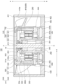
- FIG. 1 is a cross-sectional view showing a configuration of a blower according to an embodiment that is an example of the present invention.
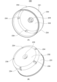
- 1A is a perspective view showing a configuration of a yoke according to an embodiment that is an example of the present invention, as viewed from the downstream side
- FIG. 1B is a perspective view showing a configuration of the yoke as viewed from the upstream side.
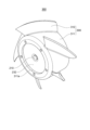
- 1 is a perspective view showing a configuration of a combined body of an impeller and a yoke of a blower according to an embodiment that is an example of the present invention, as viewed from the upstream side.
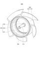
- FIG. 1 is a perspective view showing a configuration of a combination of an impeller and a yoke of a blower according to an embodiment that is an example of the present invention, as viewed from the downstream side.
- FIG. 1 is a perspective view showing a configuration of an impeller of a blower according to an embodiment that is an example of the present invention.
- FIG. 4 is a partial enlarged view showing a state in which a part of an impeller according to an embodiment of the present invention is inserted into a through hole of a yoke.
- Fig. 1 is a cross-sectional view showing the configuration of a blower according to an embodiment of the present invention.
- Fig. 2 is a perspective view showing the configuration of a yoke according to an embodiment of the present invention when viewed from the downstream side (A) and the configuration of the yoke when viewed from the upstream side (B).
- Fig. 3 is a perspective view showing the configuration of a combination of an impeller and a yoke of a blower according to an embodiment of the present invention when viewed from the upstream side.
- Fig. 1 is a cross-sectional view showing the configuration of a blower according to an embodiment of the present invention.
- Fig. 2 is a perspective view showing the configuration of a yoke according to an embodiment of the present invention when viewed from the downstream side (A) and the configuration of the yoke when viewed from the upstream side (B).
- Fig. 3 is a perspective view showing the configuration of a combination of an impeller and a
- FIG. 4 is a perspective view showing the configuration of a combination of an impeller and a yoke of a blower according to an embodiment of the present invention when viewed from the downstream side.
- Fig. 5 is a perspective view showing the configuration of an impeller of a blower according to an embodiment of the present invention.
- Fig. 6 is a partial enlarged view showing a state in which a part of an impeller according to an embodiment of the present invention is inserted into a through hole of a yoke.
- the direction of arrow a along axis X is referred to as the upstream side or one side.
- the direction of arrow b along axis X is referred to as the downstream side or the other side.
- the direction of arrows ab is referred to as the upstream/downstream direction or axial direction.
- the upstream side and downstream side do not necessarily coincide with the vertical direction.
- the direction of arrows cd is referred to as the radial direction
- the direction of arrow c away from axis X is referred to as the outer side or one radial side
- the direction of arrow d approaching axis X is referred to as the inner side or the other radial side
- the direction rotating around axis X is referred to as the circumferential direction.
- the fan motor 100 serving as a blower in this embodiment is an axial fan that blows air from the upstream side (arrow a direction) to the downstream side (arrow b direction) in the X-axis direction, and has an overall rectangular cylindrical shape that is roughly square when viewed from above.
- the fan motor 100 includes a motor 200, an impeller 300 arranged upstream (in the direction of arrow a) of the shaft 210 of the motor 200, and a casing 400 that houses the motor 200 and the impeller 300.
- the impeller 300 is composed of a hub 311 and blades 312, and is driven to rotate by the motor 200.
- the fan motor 100 has an upstream opening 401 for drawing in air from the upstream side in the X-axis direction (the direction of the arrow a) through the impeller 300, and a downstream opening 402 for discharging air through the impeller 300.
- the casing 400 of the fan motor 100 includes a side wall 410 that surrounds the impeller 300 from the radially outer side (arrow c direction), a base 420 that is formed at the end on the downstream side (arrow b direction) and holds the fan motor 100, and spokes 430 consisting of multiple stator blades (fixed blades) that connect the side wall 410 and the base 420 in the radial direction (arrows cd direction).
- the sidewall 410, base 420, and spokes 430 of the casing 400 are integrally formed by injection molding of a synthetic resin such as polybutylene terephthalate reinforced with glass fiber. Note that the sidewall 410, base 420, and spokes 430 of the casing 400 may be formed from other materials.
- the side wall 410 of the casing 400 is a tube or cylindrical body that defines the air tunnel of the fan motor 100.
- the side wall 410 has an upstream opening 401 and a downstream opening 402, and has a cylindrical inner circumferential surface 410a centered on the axis X as the axis of rotation.
- the diameter of the inner circumferential surface 410a of the side wall 410 is large enough not to come into contact with the radially outer ends (in the direction of arrow c) of the blades 312 of the impeller 300.
- a predetermined gap is formed between the radially outer end (direction of arrow c) of the blades 312 of the impeller 300 and the inner circumferential surface 410a of the side wall 410.
- the side wall 410 also functions as a guard portion that protects the impeller 300.
- the base 420 of the casing 400 is formed by a substantially disk-shaped base 420a, a cylindrical outer peripheral wall 420b that extends a predetermined length from the radially outer end (arrow c direction) of the base 420a toward the upstream side (arrow a direction), and a cylindrical inner peripheral wall 420c that protrudes a predetermined length from the radially inner end (arrow d direction) on the other radial side of the base 420a toward the upstream side (arrow a direction).
- the inner peripheral wall 420c and the outer peripheral wall 420b of the base 420 are disposed radially on either side of the base 420a, and the inner peripheral wall 420c is formed longer (higher) in the X-axis direction than the outer peripheral wall 420b.
- the inner peripheral wall 420c of the base 420 has an end surface (hereinafter referred to as the "upper end surface") on the upstream side (the direction of the arrow a), and the inner peripheral end of the circuit board 500 is placed on the upper end surface and fixed thereto by adhesive or the like.
- the circuit board 500 is a printed wiring board made of a thin, annular member, having a single layer or multiple wiring layers on which electronic components that constitute a motor drive control circuit (not shown) that drives the rotor 240 of the motor 200 to rotate are mounted.
- a plurality of spokes 430 are integrally formed on the radially outer (arrow c direction) surface (hereinafter referred to as the "outer surface") of the outer peripheral wall 420b of the base 420.
- the outer peripheral wall 420b of the base 420 is supported by the side wall 410 of the casing 400 via the spokes 430.
- the base 420 and the side wall 410 of the casing 400 are integrally connected via the plurality of spokes 430.
- the motor 200 has a shaft 210, a rotor 240 arranged on the upstream side of the shaft 210 (in the direction of the arrow a), a bearing device 260, and a stator 250.
- the shaft 210 is a cylindrical member that is rotatably supported by an upstream bearing 263 and a downstream bearing 264.
- the upstream end (in the direction of the arrow a) of the shaft 210 is integrally joined to the shaft support portion 233 of the rotor yoke 230 by press-fitting, adhesive bonding, or the like.
- Bearings 263 and 264 are, for example, ball bearings. Bearings 263 and 264 are not limited to ball bearings, and may be various other bearings, such as sleeve bearings. In addition, a coil spring sp for applying preload to bearing 263 is interposed around shaft holder 233 between the upstream end of bearing 263 and disk portion 232 of rotor yoke 230.
- the bearing device 260 has an upstream bearing 263, a downstream bearing 264, and a retaining member 262 that holds the two bearings 263, 264.
- the retaining member 262 is made of metal and has an overall generally hollow cylindrical shape.
- the retaining member 262 is press-fitted into the inner circumferential surface (the radially inner surface) of the inner circumferential wall 420c of the base 420.
- the retaining member 262 may be formed integrally with the base 420 while being inserted into the inner circumferential wall 420c.
- Bearing 263 is disposed on the upstream side of shaft 210 (in the direction of arrow a) and rotatably supports the upstream side of shaft 210 (in the direction of arrow a) with respect to holding member 262.
- Bearing 264 is disposed on the downstream side of shaft 210 (in the direction of arrow b) and rotatably supports the downstream side of shaft 210 (in the direction of arrow b) with respect to holding member 262.
- Motor 200 is an outer rotor type single-phase brushless DC motor, and has rotor 240 and stator 250. Note that motor 200 is not limited to being a single-phase brushless DC motor, and may be other motors, such as a three-phase brushless DC motor.
- the rotor 240 is fixed to the upstream side (in the direction of the arrow a) of the shaft 210.
- the rotor 240 has a rotor yoke 230 and a magnet mg.
- the rotor yoke 230 has a cylindrical portion 231, a disk portion 232, and a shaft holding portion 233.
- the cylindrical portion 231 of the rotor yoke 230 is a cylindrical portion formed of a soft magnetic material and arranged coaxially with the shaft 210. As shown in FIG. 1, a cylindrical magnet mg is fixed integrally to the inner peripheral surface (diametrically inner surface) of the cylindrical portion 231 coaxially with the cylindrical portion 231.
- the cylindrical portion 231 functions as a portion that prevents leakage of the magnetic field of the magnet mg.
- the disk portion 232 of the rotor yoke 230 is a roughly disk-shaped portion that extends from the upstream end of the cylindrical portion 231 toward the shaft 210 radially inward (in the direction of arrow d) and blocks the upstream side of the cylindrical portion 231 (in the direction of arrow a).
- the shaft retaining portion 233 is a generally cylindrical portion that protrudes a predetermined length from the end of the disk portion 232 on the radially inner side (in the direction of the arrow d) toward the downstream bearing 263 (in the direction of the arrow b).
- the inner diameter of the shaft retaining portion 233 is formed to be slightly smaller than the outer diameter of the shaft 210.
- the shaft 210 is press-fitted into the inner circumferential surface (the surface facing radially inward (in the direction of arrow d)) of the shaft retaining portion 233, thereby fixing the rotor yoke 230 and the shaft 210 together.
- the cylindrical portion 231 and the disk portion 232 of the rotor yoke 230 are fixed together to the inner circumferential surface of the hub 311 of the impeller 300 by insert molding or the like.
- the rotor yoke 230 has a plurality of (e.g., five) through holes 234 that penetrate radially through the cylindrical portion 231 at the upstream end (direction of arrow a) of the cylindrical portion 231 and at the radially outer end (direction of arrow c) of the disk portion 232, i.e., at the corner where the cylindrical portion 231 and the disk portion 232 intersect.
- These through holes 234 are rectangular in plan view, and are holes into which molten resin enters when the rotor yoke 230 and the hub 311 of the impeller 300 are insert-molded together. After the protrusions 350 (FIGS. 1, 5, and 6) of the hub 311 are formed by insert molding, the through holes 234 also serve as entrances into which the protrusions 350 enter. In this case, five through holes 234 are provided, but this is not limited to this and any number may be used.
- the stator 250 (FIG. 1) is attached to the outer peripheral surface (the radially outer surface) of the retaining member 262. However, the stator 250 may be attached directly to the base 420 without using the retaining member 262.
- the stator 250 has a stator core 251 formed by stacking multiple electromagnetic steel cores made of soft magnetic material, an insulator 252 made of an insulating material attached to the stator core 251, and a coil (not shown) wound around the stator core 251 via the insulator 252.
- the stator core 251 and the coil are insulated by the insulator 252.
- the rotor 240 rotates together with the shaft 210 due to the electromagnetic action between the rotor 240 and the stator 250, causing the impeller 300 fixed integrally to the rotor 240 to rotate, and air (hereinafter also referred to as "air flow”) is sent from the upstream side (direction of arrow a) to the downstream side (direction of arrow b) by the action of the multiple blades 312. Therefore, the fan motor 100 functions as a blower.
- the impeller 300 has a hub 311 that is cup-shaped with a cross section that is roughly an inverted U-shape with a bottom, and a number of blades 312 that are provided at regular intervals in the circumferential direction on the outer peripheral surface, which is the radially outer surface of the hub 311.
- the hub 311 In the axial direction, the hub 311 has an opening 311a that opens at the upstream end (arrow a direction), and the upstream end face (arrow a direction) of the shaft 210 and the disk portion 232 are exposed through the opening 311a ( Figure 1) ( Figure 3).
- the state in which the impeller 300 and the rotor yoke 230 are fixed together is called a combined body 360, and will be used in the following explanation.
- the multiple blades 312 of the impeller 300 that make up the combined body 360 all have the same shape and are evenly spaced around the hub 311.
- the hub 311 and the multiple blades 312 are integrally formed by injection molding of a synthetic resin such as polybutylene terephthalate reinforced with glass fiber.
- the hub 311 of the impeller 300 is fixed to the radially outer (arrow c) end of the upper end surface 232u on the upstream side (arrow a) of the disk portion 232 of the rotor yoke 230, covering the radially outer (arrow c) outer peripheral surface of the cylindrical portion 231.
- the hub 311 of the impeller 300 forms a cup shape with a cross section that is roughly an inverted U-shape with a bottom, and has a cylindrical portion 330 formed coaxially with the shaft 210, and a disk-shaped upper cover portion 340 that extends from the upstream end (direction of arrow a) of the cylindrical portion 330 toward the shaft 210.
- the upper cover portion 340 of the hub 311 has an opening 311a (Fig. 1) of a predetermined radius centered on the X-axis, and the upstream end face (direction of arrow a) of the shaft 210 and the disk portion 232 of the rotor yoke 230 are exposed through the opening 311a (Figs. 1 and 3).
- the cylindrical portion 330 of the hub 311 has protrusions 350 that enter multiple (e.g., five) through holes 234 provided in the cylindrical portion 231 of the rotor yoke 230.
- the protrusions 350 are formed in a generally rectangular cross-section and annular shape that enter from the through holes 234 of the cylindrical portion 231 of the rotor yoke 230 toward the shaft 210 and extend in the circumferential direction.
- the protrusion 350 has an inner peripheral surface 350n on the radially inward side (in the direction of the arrow d), and has an annular locking portion 352 that extends from the inner peripheral surface 350n at the upstream end (in the direction of the arrow a) of the protrusion 350 so as to protrude slightly toward the shaft 210 on the radially inward side (in the direction of the arrow d).
- the protrusion 350 refers to the portion surrounded by the dashed line and the inner peripheral surface 350n in FIG. 6.
- the protrusion 350 also has an annular protruding portion 353 that extends slightly downstream (in the direction of arrow b) along the X-axis direction beyond the upper end surface 231u on the upstream side (in the direction of arrow a) of the cylindrical portion 231 of the rotor yoke 230.
- the protruding portion 353 is flush with the inner peripheral surface 350n of the projection 350.
- the outer diameter r1 of the protruding portion 353 is smaller than the inner diameter r2 of the cylindrical portion 231 of the rotor yoke 230.
- This protruding portion 353 has a flat lower end surface 353d on the downstream side (direction of arrow b), and this lower end surface 353d is adjacent to the upper end surface mgu on the upstream side (direction of arrow a) of the magnet mg with a small gap between them.
- this is not limited to this, and the lower end surface 353d of the protruding portion 353 may abut against the upper end surface mgu on the upstream side (direction of arrow a) of the magnet mg.
- the protrusion 350 has a predetermined distance d1 (r2-r1) between the inner peripheral surface 231n on the radially inner side (direction of arrow d) of the cylindrical portion 231 of the rotor yoke 230 and the outer peripheral surface 353g on the radially outer side (direction of arrow c) of the protruding portion 353.
- a pocket space 350p is formed as an annular groove between the protruding portion 353 of the protrusion 350, the cylindrical portion 231 of the rotor yoke 230, and the upper end surface mgu of the magnet mg.
- the cylindrical portion 231 of the rotor yoke 230 is inserted into the hub 311 in a mold, and the molten resin of the hub 311 is poured into the through hole 234 of the cylindrical portion 231 to form the protrusion 350 having the locking portion 352 and the protruding portion 353.
- the protrusion 350 on the hub 311 of the impeller 300 is integrally formed in a state where it fits into the through hole 234 of the cylindrical portion 231 of the rotor yoke 230, so that the impeller 300 can be prevented from coming out of the rotor yoke 230 due to centrifugal force when the impeller 300 rotates.
- the protrusion 350 which is part of the hub 311, fits into the through hole 234 in the cylindrical portion 231 of the rotor yoke 230. This allows the fan motor 100 to be compact by reducing its overall height without being too long in the X-axis direction of the shaft 210.
- the lower end surface 353d of the protruding portion 353 of the protrusion 350 can be brought into contact with the upper end surface mgu of the magnet mg. This makes it easy to determine the height in the X-axis direction when fixing the magnet mg to the inner circumferential surface 231n of the cylindrical portion 231 in the fan motor 100.
- the three elements of the cylindrical portion 231, the protruding portion 353, and the magnet mg form a pocket space 350p that is rectangular in cross section and annular.
- the magnet mg is pressed against the inner circumferential surface 231n of the cylindrical portion 231 and is pushed up from the downstream side (arrow b direction) to the upstream side (arrow a direction) until it is adjacent to or abuts the lower end surface 353d of the protruding portion 353.
- the adhesive present between the inner circumferential surface 231n of the cylindrical portion 231 and the magnet mg is also squeezed by the magnet mg and pushed up upstream (in the direction of the arrow a), so that the pushed-up adhesive can be stored in the pocket space 350p.
- the pocket space 350p of the protrusion 350 can naturally accommodate not only the adhesive but also burrs.
- the disk portion 232 is also sandwiched between the upper cover portion 340 of the rotor yoke 230 and the locking portion 352 of the protrusion 350.
- the hub 311 of the impeller 300 and the disk portion 232 of the rotor yoke 230 are firmly fixed together, preventing the impeller 300 from slipping out of the rotor yoke 230 to the upstream side in the X-axis direction (in the direction of arrow a) when the impeller 300 rotates.
- blower of the present invention is not limited to the configuration of the above embodiment.
- the fan motor 100 is an outer rotor type motor, but the motor of the present invention may be an inner rotor type motor.
- a through hole 234 that is rectangular in plan view is provided at the end of the disk portion 232 on the radially outer side (in the direction of the arrow c), i.e., at the corner where the cylindrical portion 231 and the disk portion 232 intersect.
- the present invention is not limited to this, and a through hole that is circular in plan view or has various other shapes may be provided in part of the cylindrical portion 231, and the protrusion 350 of the hub 311 may fit into the through hole.
- blower device of the present invention can appropriately modify the blower device of the present invention and change the combination of various components according to previously known knowledge. As long as the configuration of the present invention is still provided even after such modifications, it is of course included in the scope of the present invention.
Landscapes
- Engineering & Computer Science (AREA)
- Mechanical Engineering (AREA)
- General Engineering & Computer Science (AREA)
- Power Engineering (AREA)
- Structures Of Non-Positive Displacement Pumps (AREA)
- Connection Of Motors, Electrical Generators, Mechanical Devices, And The Like (AREA)
Abstract
送風装置としての性能を低下させることなく従来よりも一段と小型化する。 本発明の送風装置(100)は、シャフト(210)と、シャフト(210)に固定されたヨーク(230)と、ヨーク(230)に固定されたインペラ(300)と、を備え、ヨーク(230)は、インペラ(300)の回転軸(X軸)の方向に延びる円筒部(231)を有し、円筒部(231)は、インペラ(300)の径方向に向かって貫通した貫通孔(234)を有し、貫通孔(234)に対して、インペラ(300)の一部が入り込んでいる。
Description
本発明は、送風装置に関する。
従来、簡易な構成により防水機能、および、防塵機能を備えるアウターロータ型の送風機が提案されている。この送風機では、ロータヨークの円筒部の内周面にマグネットが固定され、ロータヨークの円盤状の天板部に設けられた貫通孔に対して、インペラのハブの一部が入り込んだ構成を有している(例えば、特許文献1を参照。)。
しかしながら、特許文献1の送風機においては、ロータヨークの天板部に設けられた貫通孔にハブの一部が入り込んだ構成となっているため、全体的にシャフトの軸方向に長くなり、送風機全体の高さを低くして小型することが困難であった。
また、ロータヨークの天板部の下方にはステータコイルが配置されているため、構造を変更することなく小型化する場合には、ステータコイルを小型化しなければならず、性能の低下を避けられなかった。
本発明の送風装置においては、送風装置としての性能を低下させることなく従来よりも一段と小型化することを課題の一例とする。
本発明の送風装置は、シャフトと、前記シャフトに固定されたヨークと、前記ヨークと固定されたインペラと、を備え、前記ヨークは、前記インペラの回転軸の方向に延びる円筒部を有し、前記円筒部は、前記インペラの径方向に向かって貫通した貫通孔を有し、前記貫通孔に対して、前記インペラの一部が入り込んでいる。
以下、本発明の一例である実施の形態について図面を参照しながら説明する。図1は、本発明の一例である実施の形態にかかる送風装置の構成を示す断面図である。図2は、本発明の一例である実施の形態にかかるヨークを下流側から見た場合の構成(A)、および、ヨークを上流側から見た場合の構成(B)を示す斜視図である。図3は、本発明の一例である実施の形態にかかる送風装置のインペラおよびヨークの結合体を上流側から見た場合の構成を示す斜視図である。図4は、本発明の一例である実施の形態にかかる送風装置のインペラおよびヨークの結合体を下流側から見た場合の構成を示す斜視図である。図5は、本発明の一例である実施の形態にかかる送風装置のインペラの構成を示す斜視図である。図6は、本発明の一例である実施の形態にかかるインペラの一部がヨークの貫通孔に入り込んでいる状態を示す部分拡大図である。
なお、本発明の実施の形態の説明において、説明の便宜上、軸Xに沿った矢印a方向を上流側または一方側とする。軸Xに沿った矢印b方向を下流側または他方側とする。ここで、矢印ab方向を上下流方向または軸方向と称する。ただし、上流側、および、下流側は、鉛直方向とは必ずしも一致しない。また、矢印cd方向を径方向と称し、軸Xから離れる矢印c方向を外側または径方向一方側、軸Xに近づく矢印d方向を内側または径方向他方側と称する。さらに、軸Xの周りに回転する方向を周方向と称する。
図1に示すように、本実施の形態にかかる送風装置としてのファンモータ100は、X軸方向の上流側(矢印a方向)から下流側(矢印b方向)に向かって空気を送る軸流ファンであり、全体的に平面視略正方形の角筒形状を有している。
ファンモータ100は、モータ200と、モータ200のシャフト210の上流側(矢印a方向)に配置されるインペラ300と、モータ200およびインペラ300を収容するケーシング400とを備えている。
インペラ300は、ハブ311および羽根312からなり、モータ200により回転駆動される。ファンモータ100は、X軸方向の上流側(矢印a方向)からインペラ300を介して空気を吸入するための上流側の開口部401と、インペラ300を介して空気を排出するための下流側の開口部402とを有している。
ファンモータ100のケーシング400は、インペラ300の周囲を径方向一方側である径方向外側(矢印c方向)から囲う側壁410と、下流側(矢印b方向)の端部に形成され、ファンモータ100を保持するベース420と、側壁410とベース420とを径方向(矢印cd方向)において繋ぐ複数の静翼(固定翼)からなるスポーク430とを備えている。
ケーシング400の側壁410、ベース420、および、スポーク430は、例えばガラス繊維により強化されたポリブチレンテレフタレート等の合成樹脂の射出成形により一体に形成されている。なお、ケーシング400の側壁410、ベース420、および、スポーク430は、その他の素材により形成されていてもよい。
ケーシング400の側壁410は、ファンモータ100の風洞部を画定する筒または筒状体である。側壁410は、上流側の開口部401および下流側の開口部402を有すると共に、回転軸としての軸Xを中心とする円筒形状の内周面410aを有する。側壁410の内周面410aの直径は、インペラ300の羽根312の径方向外側(矢印c方向)の端部と接触しない大きさとなっている。
すなわち、インペラ300の羽根312の径方向外側(矢印c方向)の端部と、側壁410の内周面410aとの間には、所定の隙間が形成されている。なお、側壁410は、インペラ300を保護するガード部としても機能する。
ケーシング400のベース420は、略円盤形状の基部420aと、基部420aの径方向外側(矢印c方向)の端部から上流側(矢印a方向)へ所定の長さだけ延在する円筒形状の外周壁420bと、基部420aの径方向他方側である径方向内側(矢印d方向)の端部から上流側(矢印a方向)へ所定の長さだけ突出する円筒形状の内周壁420cとによって形成されている。
ベース420の内周壁420cおよび外周壁420bは、径方向において基部420aを挟んで配置されており、内周壁420cは外周壁420bよりもX軸方向に長く(高く)形成されている。
また、ベース420の内周壁420cは、上流側(矢印a方向)の端面(以下、これを「上端面」と呼ぶ。)を有し、その上端面には回路基板500の内周側の端部が載置された状態で接着等により一体に固定されている。
回路基板500は、薄板状の円環状部材からなり、モータ200のロータ240を回転駆動させるモータ駆動制御回路(図示せず)を構成する電子部品が実装された単層又は複数の配線層を有するプリント配線基板である。
径方向において、ベース420の外周壁420bの径方向外側(矢印c方向)の面(以下、これを「外周面」と呼ぶ。)には、複数のスポーク430が一体に形成されている。ベース420の外周壁420bは、スポーク430を介して、ケーシング400の側壁410に支持されている。つまり、ベース420とケーシング400の側壁410とは複数のスポーク430を介して一体に結合されている。
モータ200は、シャフト210と、シャフト210の上流側(矢印a方向)に配置されるロータ240と、軸受装置260と、ステータ250と、を有する。
シャフト210は、上流側の軸受263、および、下流側の軸受264によって回転可能に保持された円柱状部材である。シャフト210は、その上流側(矢印a方向)の端部がロータヨーク230の軸保持部233に対して圧入または接着等によって一体に結合されている。
軸受263、および、軸受264は、例えばボールベアリングである。なお、軸受263および軸受264は、ボールベアリングに限られず、例えばスリーブベアリング等、その他種々の軸受であってもよい。また、軸受263の上流側の端部とロータヨーク230の円盤部232との間には、軸受263に対して予圧を与えるためのコイルバネspが軸保持部233の周囲に介装されている。
軸受装置260は、上流側の軸受263、下流側の軸受264、および、2つの軸受263、264を保持する保持部材262を有する。保持部材262は、金属により形成されており、全体として略中空円筒形状を有している。
保持部材262は、ベース420の内周壁420cの内周面(径方向内側の面)に圧入されている。なお、保持部材262は、内周壁420cにインサートした状態でベース420と一体に形成されてもよい。
軸受263は、シャフト210の上流側(矢印a方向)に配置され、シャフト210の上流側(矢印a方向)を保持部材262に対して回転可能に支持する。軸受264は、シャフト210の下流側(矢印b方向)に配置され、シャフト210の下流側(矢印b方向)を保持部材262に対して回転可能に支持する。これにより、シャフト210は、2つの軸受263および軸受264を介して保持部材262に対して相対的に回転可能に支持される。
モータ200は、アウターロータ型の単相のブラシレスDCモータであり、ロータ240と、ステータ250とを有する。なお、モータ200は、単相のブラシレスDCモータに限るものではなく、例えば三相ブラシレスDCモータ等、その他のモータであってもよい。
ロータ240は、シャフト210の上流側(矢印a方向)に固定されている。ロータ240は、ロータヨーク230およびマグネットmgを有する。ロータヨーク230は、円筒部231、円盤部232、および、軸保持部233を有する。
ロータヨーク230の円筒部231は、シャフト210と同軸上に配置された軟磁性材によって形成された円筒状部分である。円筒部231の内周面(径方向内側の面)には、図1に示すように、円筒部231と同軸上に円筒形状のマグネットmgが一体に固定されている。円筒部231は、マグネットmgの磁界の漏れを防ぐ部分として機能する。
ロータヨーク230の円盤部232は、円筒部231の上流側の端部から径方向内側(矢印d方向)のシャフト210に向かって延び、円筒部231の上流側(矢印a方向)を閉塞する略円盤状の部分である。
軸保持部233は、円盤部232の径方向内側(矢印d方向)の端部から下流側(矢印b方向)の軸受263に向かって所定の長さだけ突出する略円筒形状の部分である。軸保持部233は、その内径がシャフト210の外径よりも僅かに小さく形成されている。
軸保持部233の内周面(径方向内側(矢印d方向)の面)にはシャフト210が圧入され、これによりロータヨーク230とシャフト210とが一体に固定される。ロータヨーク230の円筒部231および円盤部232は、インペラ300のハブ311の内周面に対してインサート成型等により一体に固定されている。
さらに、図2(A)および(B)に示すように、ロータヨーク230は、円筒部231における上流側(矢印a方向)の端部であって、かつ、円盤部232における径方向外側(矢印c方向)の端部、すなわち、円筒部231と円盤部232とが交差する角部において、円筒部231を径方向に貫通する複数(例えば5個)の貫通孔234を有している。
これらの貫通孔234は、平面視矩形状であり、ロータヨーク230とインペラ300のハブ311とを一体にインサート成形する際に、溶融樹脂が入り込むための孔である。また貫通孔234は、インサート成形によりハブ311の突起部350(図1、図5および図6)が形成された後は、その突起部350が入り込んでいる入口でもある。この場合、貫通孔234は、5個設けられているが、これに限るものではなく、任意の個数であってもよい。
ステータ250(図1)は、保持部材262の外周面(径方向外側の面)に取り付けられている。ただし、ステータ250は、保持部材262を介することなく、ベース420に直接取り付けられていてもよい。
ステータ250は、軟磁性材からなる電磁鋼板のコアを複数枚積層された積層体によって形成されたステータコア251と、ステータコア251に装着された絶縁材料からなるインシュレータ252と、インシュレータ252を介してステータコア251に巻回された図示しないコイルとを有している。ステータコア251とコイルとはインシュレータ252によって絶縁されている。
モータ200が作動し、ロータ240とステータ250との電磁気的作用によりロータ240がシャフト210と共に回転すると、ロータ240と一体に固定されたインペラ300が回転し、複数の羽根312の作用により上流側(矢印a方向)から下流側(矢印b方向)に向かって空気(以下、これを「空気流」とも言う。)が送られる。したがって、ファンモータ100は、送風機として機能する。
図3および図4に示すように、インペラ300は、有底断面略逆U字状のカップ形状からなるハブ311と、ハブ311の径方向外側の面である外周面に対して周方向に一定間隔で設けられた複数の羽根312とを備えている。
軸方向において、ハブ311は、上流側(矢印a方向)の端部が開口した開口部311aを有し、その開口部311a(図1)を介してシャフト210の上流側(矢印a方向)の端面、および、円盤部232が露出している(図3)。なお、インペラ300とロータヨーク230とが一体に固定された状態を結合体360と呼び、以下の説明において用いる。
結合体360を構成しているインペラ300の複数の羽根312は、全て同じ形状を有しており、ハブ311の周方向において当間隔で均等に配置されている。ハブ311および複数の羽根312は、例えばガラス繊維により強化されたポリブチレンテレフタレート等の合成樹脂の射出成形により一体に形成されている。
図1に示すように、インペラ300のハブ311は、円筒部231の径方向外側(矢印c方向)の外周面を覆った状態で、ロータヨーク230の円盤部232における上流側(矢印a方向)の上端面232uの径方向外側(矢印c方向)の端部、および、円筒部231の外周面に対して固定されている。
図5に示すように、インペラ300のハブ311は、有底断面略逆U字状のカップ形状を形成しており、シャフト210と同軸上に形成された円筒部330と、その円筒部330の上流側(矢印a方向)の端部からシャフト210に向かって延びる円盤状の上蓋部340と、を有している。
ハブ311の上蓋部340は、X軸を中心として所定半径の開口部311a(図1)を有し、その開口部311aを介してシャフト210の上流側(矢印a方向)の端面、および、ロータヨーク230の円盤部232が露出している(図1、および、図3)。
図6に示すように、ハブ311の円筒部330は、ロータヨーク230の円筒部231に設けられた複数(例えば5個)の貫通孔234に入り込んだ突起部350を有している。突起部350は、ロータヨーク230の円筒部231の貫通孔234からシャフト210に向かって入り込んで周方向に延びた断面略矩形状かつ円環状に形成された部分である。
突起部350は、径方向内側(矢印d方向)の内周面350nを有し、突起部350の上流側(矢印a方向)の端部において内周面350nから径方向内側(矢印d方向)のシャフト210に向かって僅かに突出するように延びる環状の係止部352を有している。なお、突起部350とは、図6において、破線と内周面350nによって囲まれた部分のことである。
この係止部352の上流側(矢印a方向)の上端面352uは、ロータヨーク230の円盤部232における下流側(矢印b方向)の下端面232dと当接されており、インペラ300の回転時にハブ311が上流側(矢印a方向)へ外れてしまうことを防止している。
また、突起部350は、ロータヨーク230の円筒部231における上流側(矢印a方向)の上端面231uよりもX軸方向に沿って下流側(矢印b方向)へ僅かに延びる環状の突部分353を有している。
突部分353は、突起部350の内周面350nと面一である。突部分353の外径r1は、ロータヨーク230の円筒部231の内径r2よりも小さい。この突部分353は、下流側(矢印b方向)の平坦な下端面353dを有し、この下端面353dとマグネットmgの上流側(矢印a方向)の上端面mguとが僅かな隙間を介して隣接している。ただし、これに限るものではなく、突部分353の下端面353dとマグネットmgの上流側(矢印a方向)の上端面mguとが当接していてもよい。
突起部350は、ロータヨーク230の円筒部231における径方向内側(矢印d方向)の内周面231nと、突部分353における径方向外側(矢印c方向)の外周面353gとの間が所定の距離d1(r2-r1)だけ離れている。
これにより、突起部350の突部分353と、ロータヨーク230の円筒部231と、マグネットmgの上端面mguとの間には、環状の溝部としてのポケット空間350pが形成されている。
実際上、金型においてロータヨーク230の円筒部231をハブ311にインサートし、円筒部231の貫通孔234に当該ハブ311の溶融樹脂を流し込んで成形することにより、係止部352および突部分353を有する突起部350が形成される。
以上の構成において、ファンモータ100では、インペラ300のハブ311における突起部350がロータヨーク230の円筒部231の貫通孔234に入り込んだ状態で一体に形成されているため、インペラ300の回転時に当該インペラ300が遠心力によりロータヨーク230から抜け出てしまうことを防止することができる。
また、ファンモータ100では、従来のように、ロータヨーク230の円盤部232に貫通孔を設け、そこにインペラ300のハブ311の一部を入り込むようにするのではなく、ロータヨーク230の円筒部231の貫通孔234にハブ311の一部である突起部350を入り込ませるようにした。これによりファンモータ100は、全体的にシャフト210のX軸方向に長くならずに済み、全体の高さを低くして小型することができる。
さらに、ファンモータ100は、ロータヨーク230の円筒部231の内周面231nにマグネットmgを接着剤等により固定する際、突起部350の突部分353の下端面353dとマグネットmgの上端面mguとを当接させることができる。これにより、ファンモータ100では、円筒部231の内周面231nにマグネットmgを固定する際のX軸方向における高さを容易に決定することができる。
突起部350の突部分353の下端面353dとマグネットmgの上端面mguとを隣接または当接させた場合、円筒部231と、突部分353と、マグネットmgとの3要素により断面矩形状かつ環状のポケット空間350pが形成される。
マグネットmgは、円筒部231の内周面231nに押し当てられ、突部分353の下端面353dに隣接または当接するまで下流側(矢印b方向)から上流側(矢印a方向)へ押し上げられる。
このとき、円筒部231の内周面231nとマグネットmgとの間に存在する接着剤についても、マグネットmgによりしごかれて上流側(矢印a方向)へ押し上げられるので、押し上げられた接着剤をポケット空間350pに収容することができる。
なお、円筒部231の内周面231nに対してマグネットmgが固定される際に、接着剤を用いるのではなく、圧入される場合には、接着剤ではなく、マグネットmgの上側端部に存在するバリ等をポケット空間350pに収容することができる。
因みに、突起部350のポケット空間350pは、円筒部231の内周面231nに対してマグネットmgを接着剤で固定する場合であっても、当然に接着剤に加えてバリについても収容することができる。
ファンモータ100では、インペラ300のハブ311に設けられた突起部350の係止部352がロータヨーク230の円盤部232に係止されているだけではなく、ロータヨーク230の上蓋部340と、突起部350の係止部352との間に円盤部232を挟み付けている。
このため、インペラ300のハブ311とロータヨーク230の円盤部232とが強固に固定されることになり、インペラ300の回転時に当該インペラ300がロータヨーク230からX軸方向の上流側(矢印a方向)へ抜け出てしまうことを防止することができる。
以上、本発明の送風装置について、好ましい実施の形態を挙げて説明したが、本発明の送風装置は上記実施の形態の構成に限定されるものではない。例えば、ファンモータ100は、アウターロータ型のモータであるが、本発明のモータは、インナーロータ型のモータであってもよい。
また、本発明においては、円盤部232における径方向外側(矢印c方向)の端部、すなわち、円筒部231と円盤部232とが交差する角部に平面視矩形状の貫通孔234を設けるようにした場合について述べた。しかしながら、本発明はこれに限らず、円筒部231の一部に平面視円形やその他種々の形状からなる貫通孔を設け、その貫通孔にハブ311における突起部350が入り込むようにしてもよい。
その他、当業者は、従来公知の知見に従い、本発明の送風装置を適宜改変し、また各種構成の組み合わせを変更することができる。かかる変更によってもなお本発明の構成を具備する限り、勿論、本発明の範疇に含まれるものである。
100…ファンモータ、200…モータ、210…シャフト、230…ロータヨーク、231…円筒部、231n…内周面、232…円盤部、232u…上端面、232d…下端面、233…軸保持部、234…貫通孔、240…ロータ、250…ステータ、251…ステータコア、252…インシュレータ、260…軸受装置、262…保持部材、263,264…軸受、300…インペラ、311…ハブ、311a…開口部、312…羽根、330…円筒部、340…上蓋部、350…突起部、350n…内周面、350p…ポケット空間、352…係止部、352u…上端面、353…突部分、353g…外周面、353d…下端面、360…結合体、400…ケーシング、401,402…開口部、410…側壁、410a…内周面、420…ベース、420a…基部、420b…外周壁、420c…内周壁、430…スポーク、500…回路基板、sp…コイルバネ、mg…マグネット、mgu…上端面。
Claims (6)
- シャフトと、
前記シャフトに固定されたヨークと、
前記ヨークに固定されたインペラと、
を備え、
前記ヨークは、前記インペラの回転軸の方向に延びる円筒部を有し、
前記円筒部は、前記インペラの径方向に向かって貫通した貫通孔を有し、
前記貫通孔に対して、前記インペラの一部が入り込んでいる、
送風装置。 - 前記インペラは、前記インペラの径方向において前記シャフトに向かって延びる突起部を有し、
前記突起部が前記貫通孔に入り込んでいる
請求項1に記載の送風装置。 - 前記突起部の端部には、前記回転軸の方向に延びる環状の突部分を有する
請求項2に記載の送風装置。 - 前記インペラは、前記回転軸の方向に凹む環状の溝部を有し、
前記溝部は、前記径方向において前記突部分と前記円筒部の内周面との間に形成され、
前記円筒部の内周面にはマグネットが固定され、
前記マグネットは、前記溝部と隣接している、
請求項3に記載の送風装置。 - 前記マグネットは、前記突部分の軸方向における端面と接触している
請求項4に記載の送風装置。 - 前記溝部は、前記マグネットを前記円筒部の内周面に固定する際の接着剤を収容可能な環状のポケット空間である、
請求項4または5に記載の送風装置。
Priority Applications (1)
| Application Number | Priority Date | Filing Date | Title |
|---|---|---|---|
| CN202480032923.7A CN121195116A (zh) | 2023-06-16 | 2024-06-13 | 送风装置 |
Applications Claiming Priority (2)
| Application Number | Priority Date | Filing Date | Title |
|---|---|---|---|
| JP2023099508A JP2024180072A (ja) | 2023-06-16 | 2023-06-16 | 送風装置 |
| JP2023-099508 | 2023-06-16 |
Publications (1)
| Publication Number | Publication Date |
|---|---|
| WO2024257820A1 true WO2024257820A1 (ja) | 2024-12-19 |
Family
ID=93852199
Family Applications (1)
| Application Number | Title | Priority Date | Filing Date |
|---|---|---|---|
| PCT/JP2024/021436 Ceased WO2024257820A1 (ja) | 2023-06-16 | 2024-06-13 | 送風装置 |
Country Status (3)
| Country | Link |
|---|---|
| JP (1) | JP2024180072A (ja) |
| CN (1) | CN121195116A (ja) |
| WO (1) | WO2024257820A1 (ja) |
Citations (3)
| Publication number | Priority date | Publication date | Assignee | Title |
|---|---|---|---|---|
| JP2009250158A (ja) * | 2008-04-09 | 2009-10-29 | Nippon Densan Corp | 送風ファン |
| WO2021153661A1 (ja) * | 2020-01-28 | 2021-08-05 | ミネベアミツミ株式会社 | モータ及び送風装置 |
| JP2022054430A (ja) * | 2020-09-25 | 2022-04-06 | ミネベアミツミ株式会社 | ファン装置 |
-
2023
- 2023-06-16 JP JP2023099508A patent/JP2024180072A/ja active Pending
-
2024
- 2024-06-13 WO PCT/JP2024/021436 patent/WO2024257820A1/ja not_active Ceased
- 2024-06-13 CN CN202480032923.7A patent/CN121195116A/zh active Pending
Patent Citations (3)
| Publication number | Priority date | Publication date | Assignee | Title |
|---|---|---|---|---|
| JP2009250158A (ja) * | 2008-04-09 | 2009-10-29 | Nippon Densan Corp | 送風ファン |
| WO2021153661A1 (ja) * | 2020-01-28 | 2021-08-05 | ミネベアミツミ株式会社 | モータ及び送風装置 |
| JP2022054430A (ja) * | 2020-09-25 | 2022-04-06 | ミネベアミツミ株式会社 | ファン装置 |
Also Published As
| Publication number | Publication date |
|---|---|
| CN121195116A (zh) | 2025-12-23 |
| JP2024180072A (ja) | 2024-12-26 |
Similar Documents
| Publication | Publication Date | Title |
|---|---|---|
| US7737589B2 (en) | Axial fan motor | |
| US9062567B2 (en) | Fan | |
| JP7080621B2 (ja) | アウターロータモータ及びこれを備える掃除機 | |
| US20140205476A1 (en) | Electric fan | |
| US20170248145A1 (en) | Outer-rotor motor and blower having the same | |
| US6700262B2 (en) | Rotary electric machine | |
| CN110417135A (zh) | 定子单元、马达以及送风装置 | |
| KR100887536B1 (ko) | 더블 로터/단일 스테이터 방식의 코어레스형 비엘디씨모터를 이용한 차량 공기청정기용 블로워 | |
| WO2024257820A1 (ja) | 送風装置 | |
| JP2010239858A (ja) | モータ | |
| JP3126341B2 (ja) | 軸流ファンの回転子 | |
| US20050275299A1 (en) | Motor with rotational balancing structure | |
| KR102087523B1 (ko) | 팬 모터 | |
| JP4004846B2 (ja) | モータ | |
| CN111749985A (zh) | 气体动压轴承、马达以及风扇马达 | |
| JPH08191554A (ja) | 冷却ファン付き外転ロータ型直流電動機 | |
| WO2023188597A1 (ja) | モータ | |
| JP7645714B2 (ja) | モータ | |
| KR100789514B1 (ko) | 무정류자 전동기 | |
| JP2002010604A (ja) | 電動機 | |
| CN119631281A (zh) | 马达 | |
| KR20250166535A (ko) | 무인비행장치용 모터 | |
| CN110138107B (zh) | 内定子组件以及叶片与外转子一体化风机 | |
| JP2002242882A (ja) | 軸流ファン | |
| JPWO2018142465A1 (ja) | アキシャルギャップ型回転電機 |
Legal Events
| Date | Code | Title | Description |
|---|---|---|---|
| 121 | Ep: the epo has been informed by wipo that ep was designated in this application |
Ref document number: 24823435 Country of ref document: EP Kind code of ref document: A1 |
|
| WWE | Wipo information: entry into national phase |
Ref document number: CN2024800329237 Country of ref document: CN |
|
| NENP | Non-entry into the national phase |
Ref country code: DE |