WO2024257720A1 - 車載装置、サービス提供システム、サービス提供方法およびサービス提供プログラム - Google Patents
車載装置、サービス提供システム、サービス提供方法およびサービス提供プログラム Download PDFInfo
- Publication number
- WO2024257720A1 WO2024257720A1 PCT/JP2024/021020 JP2024021020W WO2024257720A1 WO 2024257720 A1 WO2024257720 A1 WO 2024257720A1 JP 2024021020 W JP2024021020 W JP 2024021020W WO 2024257720 A1 WO2024257720 A1 WO 2024257720A1
- Authority
- WO
- WIPO (PCT)
- Prior art keywords
- vehicle
- access
- api
- future
- usage fee
- Prior art date
- Legal status (The legal status is an assumption and is not a legal conclusion. Google has not performed a legal analysis and makes no representation as to the accuracy of the status listed.)
- Ceased
Links
Images






Classifications
-
- G—PHYSICS
- G06—COMPUTING OR CALCULATING; COUNTING
- G06Q—INFORMATION AND COMMUNICATION TECHNOLOGY [ICT] SPECIALLY ADAPTED FOR ADMINISTRATIVE, COMMERCIAL, FINANCIAL, MANAGERIAL OR SUPERVISORY PURPOSES; SYSTEMS OR METHODS SPECIALLY ADAPTED FOR ADMINISTRATIVE, COMMERCIAL, FINANCIAL, MANAGERIAL OR SUPERVISORY PURPOSES, NOT OTHERWISE PROVIDED FOR
- G06Q30/00—Commerce
- G06Q30/06—Buying, selling or leasing transactions
- G06Q30/0645—Rental transactions; Leasing transactions
-
- G—PHYSICS
- G06—COMPUTING OR CALCULATING; COUNTING
- G06Q—INFORMATION AND COMMUNICATION TECHNOLOGY [ICT] SPECIALLY ADAPTED FOR ADMINISTRATIVE, COMMERCIAL, FINANCIAL, MANAGERIAL OR SUPERVISORY PURPOSES; SYSTEMS OR METHODS SPECIALLY ADAPTED FOR ADMINISTRATIVE, COMMERCIAL, FINANCIAL, MANAGERIAL OR SUPERVISORY PURPOSES, NOT OTHERWISE PROVIDED FOR
- G06Q50/00—Information and communication technology [ICT] specially adapted for implementation of business processes of specific business sectors, e.g. utilities or tourism
- G06Q50/10—Services
Definitions
- This disclosure relates to an in-vehicle device that provides services to a vehicle, a service provision system, a service provision method, and a service provision program.
- Patent Document 1 describes a sharing mobility system that includes multiple user terminals used by users who use vehicles, multiple carport devices installed in carports, and a server managed by a business that provides mobility services to users.
- the server calculates the expected amount of revenue that the business can obtain from a user when the user uses a vehicle that is parked in the carport and available for use.
- a service provider When a service provider provides a service to a vehicle, it may be necessary for the service provider to obtain vehicle information from the target vehicle for which the service is being provided, or to have the target vehicle perform a specified operation or process.
- This disclosure will reduce fluctuations in fees incurred by service providers when they use vehicles.
- One aspect of the present disclosure is an in-vehicle device that is mounted in a vehicle and connected to multiple electronic control devices via an in-vehicle network.
- the in-vehicle device of the present disclosure includes a cooperation control unit configured to realize cooperation between a service application configured to provide a service to a vehicle and a functional block configured to execute predetermined processing in the vehicle.
- the functional block includes a functional interface configured to convert an access request expressed in a vehicle-independent format and transmitted from the service application into a vehicle-dependent format.
- the cooperation control unit is configured to transfer the access request transmitted from the service application to the functional block.
- the collaboration control unit includes an access control method determination unit and an access permission determination unit.
- the access control method determination unit is configured to determine an access control method for controlling the transfer of access requests to the functional block based on current interface usage fee information, future estimated amount information, and interface usage conditions set for use of the functional interface by a servicer that provides services to vehicles using a service application.
- the current interface usage fee information indicates the current interface usage fee, which is the interface usage fee incurred as a result of the service application using the functional interface at the current time.
- the future estimated amount information indicates the future estimated amount, which is the estimated amount of interface usage fee that will be incurred as a result of the service application using the functional interface in the future.
- the access permission determination unit is configured to determine whether to permit an access request based on the access control method determined by the access control method determination unit and a request from a vehicle control system including a plurality of electronic control units and an in-vehicle device.
- the in-vehicle device of the present disclosure configured in this manner can cause a service application to use a functional interface when the current interface usage fee and future forecast amount satisfy the interface usage conditions set by the servicer. This makes it possible for the in-vehicle device of the present disclosure to prevent the occurrence of a situation in which a service application uses a functional interface when the current interface usage fee and future forecast amount are higher than the servicer expects. As a result, the in-vehicle device of the present disclosure can prevent fluctuations in fees that occur when the servicer uses a vehicle.
- a service providing system including a vehicle control system equipped with a plurality of electronic control devices mounted on a vehicle and connected to an in-vehicle network, the vehicle control system including a cooperation control unit configured to realize cooperation between a service application and a functional block, and a server configured to be capable of data communication with the vehicle control system.
- the cooperation control unit includes an access control method determination unit and an access permission determination unit.
- the service provision system of the present disclosure configured in this manner is a system equipped with the in-vehicle device of the present disclosure, and can achieve the same effects as the in-vehicle device of the present disclosure.
- Another aspect of the present disclosure is a service provision method executed by an in-vehicle device that is mounted on a vehicle and connected to multiple electronic control devices via an in-vehicle network.
- the in-vehicle device includes a function interface and a cooperation control unit.
- the in-vehicle device determines an access control method for controlling the transfer of an access request to a function block based on current interface usage fee information, future forecast amount information, and interface usage conditions set for using the function interface by a servicer that provides a service to a vehicle using a service application.
- the in-vehicle device also determines whether to permit the access request based on the determined access control method and a request from a vehicle control system that includes multiple electronic control devices and the in-vehicle device.
- the service provision method disclosed herein is a method executed by the in-vehicle device disclosed herein, and by executing the method, it is possible to obtain the same effects as the in-vehicle device disclosed herein.
- Another aspect of the present disclosure is a service provision program for causing a computer of an in-vehicle device that is mounted in a vehicle and connected to multiple electronic control devices via an in-vehicle network to function as a functional interface, a cooperation control unit, an access control method determination unit, and an access permission determination unit.
- a computer controlled by the service provision program disclosed herein can form part of the in-vehicle device disclosed herein, and can achieve the same effects as the in-vehicle device disclosed herein.
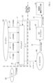
- FIG. 1 is a block diagram showing a configuration of a service providing system.
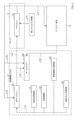
- FIG. 2 is a block diagram showing the configuration of an ECU.
- FIG. 13 is a block diagram showing a charging procedure.
- FIG. 1 is a block diagram showing an information transmission path.
- FIG. 2 is a block diagram illustrating the operation of the service providing system.
- FIG. 13 is a diagram showing a usage setting table.
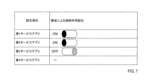
- FIG. 13 is a diagram showing a method for setting compulsory use.
- FIG. 11 is a diagram showing a first specific example of determining an access control method.
- FIG. 11 is a diagram showing a second specific example of determining an access control method.
- 4 is a block diagram illustrating the operation of an access permission determining unit and an access control executing unit.
- FIG. 4 is a block diagram illustrating the operation of an access control execution unit and an access log management unit.
- FIG. 11 is a sequence diagram showing a procedure for setting API usage conditions and a procedure for setting whether or not API usage is forcibly enabled;
- FIG. 11 is a sequence diagram showing a procedure for determining whether access is permitted.
- 11 is a sequence diagram showing a procedure for allowing a user to set whether or not to forcibly use an API.
- the service providing system 1 of this embodiment includes a vehicle control system 2 and a server 3.
- the vehicle control system 2 is mounted on the vehicle and has the function of communicating data with the server 3 via the wide area wireless communication network NW.
- the server 3 has a function of performing data communication with the vehicle control system 2 via the wide area wireless communication network NW.
- the server 3 is provided with an app store that can be accessed via the wide area wireless communication network NW or the Internet.
- a vehicle equipped with vehicle control system 2 may have an automatic driving function in addition to a manual driving function.
- the vehicle may be a hybrid vehicle having an engine and an electric motor as a driving source.
- the vehicle is not limited to a vehicle having an automatic driving function or a hybrid vehicle, but may be a vehicle equipped with only a manual driving function, or a vehicle having only an engine or only an electric motor as a driving source.
- a vehicle equipped with vehicle control system 2 will be simply referred to as a vehicle.
- the vehicle control system 2 includes one ECU 4, multiple ECUs 5, multiple ECUs 6, an external communication device 7, and an internal communication network 8.
- ECU stands for Electronic Control Unit.
- the ECU 4 manages multiple ECUs 5 to achieve coordinated control of the entire vehicle.
- An ECU 5 is provided for each domain that is divided according to the vehicle's functions, and mainly controls the multiple ECUs 6 that exist within that domain.
- Each ECU 5 is connected to the subordinate ECUs 6 via a lower-level network (e.g., CAN) that is provided individually for each ECU 5.
- CAN is an abbreviation for Controller Area Network.
- Examples of domains include the powertrain, body, chassis, and cockpit.
- the ECUs 6 connected to the ECUs 5 belonging to the powertrain domain include, for example, an ECU 6 that controls the engine, an ECU 6 that controls the motor, and an ECU 6 that controls the battery.
- the ECUs 6 connected to the ECU 5 belonging to the body domain include, for example, an ECU 6 that controls the air conditioner and an ECU 6 that controls the doors.
- the ECUs 6 connected to the ECU 5 belonging to the chassis domain include, for example, an ECU 6 that controls the brakes and an ECU 6 that controls the steering.
- the ECUs 6 connected to the ECUs 5 belonging to the cockpit domain include, for example, an ECU 6 that controls the display of meters and navigation, and an ECU 6 that controls input devices operated by vehicle occupants.
- the external vehicle communication device 7 communicates data with the server 3 via the wide area wireless communication network NW.
- the in-vehicle communication network 8 includes CAN FD and Ethernet.
- Ethernet is a registered trademark.
- CAN FD is an abbreviation for CAN with Flexible Data Rate.
- the CAN FD connects the ECU 4 to each ECU 5 and the external-vehicle communication device 7 via a bus.
- the Ethernet individually connects the ECU 4 to each ECU 5 and the external-vehicle communication device 7.
- ECU4 is an electronic control device that is mainly composed of a microcomputer equipped with a CPU4a, ROM4b, RAM4c, etc.
- Various functions of the microcomputer are realized by CPU4a executing a program stored in a non-transient physical recording medium.
- ROM4b corresponds to the non-transient physical recording medium that stores the program.
- a method corresponding to the program is executed. Note that some or all of the functions executed by CPU4a may be configured in hardware using one or more ICs, etc. Also, the number of microcomputers that make up ECU4 may be one or more.
- the ECU 4 further includes a flash ROM 4d.
- the flash ROM 4d is a non-volatile memory whose contents can be rewritten.
- ECU5, ECU6, and external communication device 7 are all electronic control devices that are mainly composed of a microcomputer equipped with a CPU, ROM, RAM, etc., just like ECU4.
- the number of microcomputers that make up ECU5, ECU6, and external communication device 7 may be one or more.
- ECU5 controls one or more ECUs 6.
- ECU4 controls one or more ECUs 5, 6, or controls the ECUs 5, 6 and external communication device 7 of the entire vehicle.
- ECU4, ECU5, ECU6, and external communication device 7 will be referred to as in-vehicle devices 4 to 7 unless otherwise specified.
- the server 3 includes a control unit 11, a communication unit 12, and a memory unit 13.
- the control unit 11 is an electronic control device that is mainly composed of a microcomputer equipped with a CPU 11a, a ROM 11b, a RAM 11c, etc.
- the various functions of the microcomputer are realized by the CPU 11a executing a program stored in a non-transient physical recording medium.
- the ROM 11b corresponds to the non-transient physical recording medium that stores the program.
- the execution of this program executes a method corresponding to the program.
- some or all of the functions executed by the CPU 11a may be configured in hardware using one or more ICs, etc.
- the number of microcomputers that make up the control unit 11 may be one or more.
- the communication unit 12 communicates data with the vehicle control system 2 via the wide area wireless communication network NW.
- the memory unit 13 is a storage device for storing various data.
- the service providing system 1 further includes a servicer terminal device 9.
- the servicer terminal device 9 is a device managed by a service provider SV (hereinafter, servicer SV) described later, and is, for example, a personal computer.
- servicer SV service provider SV
- the servicer terminal device 9 includes a control unit 15, a communication unit 16, a memory unit 17, a display unit 18, and an operation input unit 19.
- the control unit 15 is an electronic control device that is mainly composed of a microcomputer equipped with a CPU, ROM, RAM, etc.
- the communication unit 16 communicates data with the vehicle control system 2 and the server 3 via the wide area wireless communication network NW.
- the memory unit 17 is a storage device for storing various data.
- the display unit 18 is equipped with a display device (not shown) and displays various images on the display screen of the display device.
- the operation input unit 19 outputs input operation information for identifying input operations performed by the user via a keyboard and mouse (not shown).
- the ECU 4 includes a real-time processing unit 20 and an application processing unit 30 (hereinafter, the application processing unit 30).
- the real-time processing unit 20 and the application processing unit 30 may be realized by processes executed by the same CPU, or may be realized by processes executed by different CPUs.
- the real-time processing unit 20 works with the in-vehicle devices 5 to 7 connected via the CAN FD to execute vehicle control and other tasks that require real-time performance.
- the application processing unit 30 works with the in-vehicle devices 5 to 7 connected via Ethernet to execute various applications (e.g., entertainment applications) that require high processing power.
- the application processing unit 30 has a function of transmitting instructions based on the processing of various applications to the real-time processing unit 20.
- the real-time processing unit 20 has a function of transmitting information collected from the ECU, etc. via the CAN FD to the application processing unit 30. As a result, the real-time processing unit 20 and the application processing unit 30 work together to realize various functions.
- the software of the vehicle control system 2 is built in accordance with AUTOSAR.
- AUTOSAR is an architecture for autonomous driving, and is an abbreviation for Automotive Open System Architecture.
- AUTOSAR is a registered trademark.
- AUTOSAR provides not only communication between software components (hereinafter referred to as SW-C) implemented to realize various applications, but also functions related to cloud connection and security, etc.
- SW-C is modularized software to realize a certain function.
- An application program includes one or more SW-C. Note that the software of the vehicle control system 2 does not necessarily have to be built in accordance with AUTOSAR.
- Each device belonging to the vehicle control system 2, i.e., ECU4, ECU5, ECU6 and external communication device 7, is provided with a platform.
- the platform provides an environment for executing SW-C written in a hardware-independent format.
- the platform comprises a runtime environment (hereinafter referred to as RTE) and base software (hereinafter referred to as BSW).
- RTE is an interface that connects SW-Cs with each other and between SW-Cs and BSW.
- BSW is a layer that connects the hardware and SW-Cs, and includes the OS, drivers, middleware, etc.
- the functions of the BSW are divided into small modules, and the functions of each module are provided to the SW-Cs via an API. API stands for Application Programming Interface.
- the platform provided by the real-time processing unit 20 is referred to as the first platform 21 (hereinafter, the first PF 21), and the platform provided by the application processing unit 30 is referred to as the second platform 31 (hereinafter, the second PF 31).
- the real-time processing unit 20 includes a control system function block group 22 as a collection of service applications (hereinafter, service apps) that run on the first PF 21.
- service apps are an application that receives requests from clients, processes them, and returns the results.
- the control system functional block group 22 is equipped with an API that receives commands related to the vehicle's movement, and is a group of applications that integrate the commands received by the API to realize consistent vehicle control.
- the control system functional block group 22 outputs various commands via the in-vehicle communication network 8 to the in-vehicle devices 5 to 7 that have entities that execute control based on the commands.
- the first PF 21 includes a conversion gateway 211.
- the conversion gateway 211 has a function of converting communication frames received by the real-time processing unit 20 via CAN FD into Ethernet format and providing the frames to the application processing unit 30.
- the conversion gateway 211 also has a function of converting communication frames in Ethernet format provided by the application processing unit 30 into CAN FD format.
- the application processing unit 30 includes a hypervisor 32 and executes software on multiple virtual machines. Note that the hypervisor 32 may be omitted.
- the application processing unit 30 includes a group of service function blocks 33 as a collection of service applications that run on the second PF 31.
- the service function block group 33 is a collection of service apps. Each service app has one or more SW-Cs. Service apps are provided not only by the vehicle manufacturer that produced the vehicle, but also by third parties. An example of a third party that provides a service app is a data utilization company that provides a service by collecting data from the vehicle.
- the second PF 31 includes a control system function block group 35, a data system function block group 36, and an API gateway 40.
- the control system function block group 35 is a collection of programs equipped with an API for receiving requests related to vehicle control from the service system function block group 33.
- the control system function block group 35 has an API group 37 consisting of multiple APIs, and converts API access requests from the service system function block group 33 expressed in a vehicle-independent format into API access requests expressed in a vehicle-dependent format and provides them to the real-time processing unit 20.
- the above-mentioned "vehioned "vehicle-independent format” is a format common to vehicles (i.e., a format that absorbs differences between vehicle models).
- the above-mentioned "vehicle-dependent format” is a format specific to the vehicle.
- the APIs provided in the control system function block group 35 include motion system APIs that control the vehicle's motion, and other non-motion system APIs.
- API access requests received by the motion system APIs are transferred to the control system function block group 35, and then transferred from the control system function block group 35 via the in-vehicle communication network 8 to the in-vehicle devices 5-7 that execute control based on the request.
- API access requests received by the non-motion system APIs are transferred via the in-vehicle communication network 8 to the in-vehicle devices 5-7 that execute control based on the request.
- the data system functional block group 36 is a collection of programs equipped with an API for handling vehicle data acquired and accumulated via the real-time processing unit 20.
- the data system functional block group 36 has a function of abstracting the vehicle data, which is expressed in a vehicle-dependent format and supplied from the real-time processing unit 20, into a vehicle-independent format and accumulating it.
- the data system functional block group 36 may have an API that provides a function for transmitting specified vehicle data to an ECU or the like via Ethernet. In particular, when the destination is the external vehicle communication device 7, the external vehicle communication device 7 may upload the transmitted vehicle data to the cloud.
- communication with the other on-board devices 5-7 via the control system function block group 35 is not limited to CAN FD, and Ethernet or other communication means may be used. Also, communication with the other on-board devices 5-7 via the data system function block group 36 is not limited to Ethernet, and CAN FD or other communication means may be used.
- the API gateway 40 is configured using the functions of a virtual function bus (hereinafter referred to as VFB).
- VFB is middleware that enables communication between SW-Cs and between SW-Cs and BSWs without having to be aware of hardware and communication protocols, and is also called a software bus.
- Communication between SW-Cs is access from a SW-C to an API provided by another SW-C, and communication between a SW-C and BSW is access from a SW-C to an API provided by the control system function block group 35 and the data system function block group 36.
- the SW-C accesses various APIs via the API gateway 40 and uses the functions provided by the accessed API to achieve the desired functions.
- the SW-C When using an API, the SW-C sends an API access request.
- the API access request includes at least the app ID of the service app that includes the SW-C that is the request source, and the API-ID, which is information indicating the API that is the destination of the request.
- the server 3 is provided with an app store 14.
- the app store 14 has a function of registering a service app SA produced by the servicer SV in the app store 14 based on an application by the servicer SV who accesses the app store 14 using the servicer terminal device 9.
- the service app SA registered in the app store 14 is published on the website of the app store 14.
- the app store 14 has a function of registering the API used by the service app SA in the app store 14 based on an application by the servicer SV, as indicated by the arrow L2.
- the service app SA When a user US accesses the website of the app store 14 and purchases a service app SA, the service app SA is installed in the ECU 4 mounted in the vehicle of the user US, as shown by the arrow L3.
- the API gateway 40 transfers the API access request to the control system function block group 35, as shown by arrow L5.
- the control system function block group 35 converts the API access request into an API access request expressed in a vehicle-dependent format and provides it to the real-time processing unit 20.
- the API gateway 40 transmits a statistical access log to the app store 14, which includes the number of API usages taking into account the execution success status of the API access requests and the amount of communication data associated with the API usage.
- the app store 14 calculates the API usage fee incurred when the service app SA uses the API based on the statistical access log received from the API gateway 40, and bills the servicer SV for the API usage fee.
- the servicer SV pays the billed API usage fee to the app store 14, as shown by arrow L7.
- the app store 14 calculates the app usage fee for the service app SA based on the usage status of the service app SA, and bills the user US for the app usage fee.
- the user US pays the billed app usage fee to the app store 14, as shown by arrow L8.
- the app store 14 transfers the app usage fee paid by the user US to the servicer SV, as shown by arrow L9.
- the vehicle control system 2 includes a vehicle objective management system 51, a state recognition system 52, a vehicle equipment output management system 53, and a vehicle energy management system 54.
- the vehicle objective management system 51 is composed of one or more ECUs 5 and 6, and has the function of creating a long-term plan for vehicle operation.
- the long-term plan for vehicle operation includes a driving plan, a cabin temperature plan, and an equipment operation application usage plan.
- the driving plan is created to reflect the differences in brake and accelerator characteristics that vary depending on the vehicle, as well as the differences in individual driving characteristics.
- the driving plan is, for example, a vehicle speed profile, and is represented as a two-dimensional graph with the horizontal axis representing time [s] and the vertical axis representing vehicle speed [km/h].
- the device operation application usage plan is, for example, a battery charging profile, and is represented by a two-dimensional graph with the horizontal axis representing time [s] and the vertical axis representing the charging rate [%].
- the state recognition system 52 is composed of one or more ECUs 5, 6, and has the function of creating current vehicle information, current occupant information, current surrounding information, and a vehicle CPU load profile.
- Current vehicle information is, for example, the current vehicle speed of the vehicle.
- Current occupant information is, for example, the alertness of the occupant.
- Current surrounding information is, for example, signs present around the vehicle.
- the vehicle CPU load profile is, for example, a CPU load forecast plan until arrival at the destination.
- the vehicle equipment output management system 53 is composed of one or more ECUs 5, 6, and has the function of creating current equipment operation status information and a vehicle equipment operation profile.
- the current equipment operation status information indicates, for example, whether the vehicle's lights are on or not.
- the vehicle equipment operation profile is, for example, a light usage plan for using lights in tunnels, etc., before arriving at the destination, and is represented as a two-dimensional graph with the horizontal axis being time [s] and the vertical axis being power [kWh].
- the vehicle energy management system 54 is made up of one or more ECUs 5 and 6, and has the function of creating current vehicle energy status information and long-term energy plans.
- Current vehicle energy state information is, for example, information indicating the state of charge (i.e., SOC) of an energy storage device installed in the vehicle.
- SOC stands for State Of Charge.
- the long-term energy plan is, for example, a battery load profile that predicts the SOC until the destination is reached, and is represented as a two-dimensional graph with the horizontal axis being time [s] and the vertical axis being the charging rate [%].
- the API gateway 40 acquires various information created by the vehicle purpose management system 51, the status recognition system 52, the vehicle equipment output management system 53, and the vehicle energy management system 54, and calculates the current API usage fee and the future forecast amount of the API usage fee.
- the API gateway 40 notifies the app store 14 and the service app SA of the calculated current API usage fee and the future estimated API usage fee, as indicated by arrows L12 and L13.
- the app store 14 acquires current API usage fee information indicating the current API usage fee and forecast API amount information indicating the future forecast amount of the API usage fee from the API gateways 40 of multiple vehicles.
- the app store 14 acquires information from other systems, as indicated by arrow L14.
- Information from other systems includes, for example, energy supply and demand information from power companies and rapid charger congestion information indicating the congestion status of rapid chargers.
- the app store 14 uses information obtained from the API gateways 40 of multiple vehicles and other systems to calculate future expected vehicle API usage fees.
- the app store 14 notifies the API gateway 40 and the service app SA of the calculated future estimated vehicle API usage fee, as indicated by arrows L15 and L16.
- the app store 14 notifies the servicer terminal device 9 of the current API usage fee and the future estimated amount of the API usage fee obtained from the API gateway 40, as well as the calculated future estimated amount of the vehicle API usage fee.
- the servicer terminal device 9 can set whether or not the service app SA will use the API based on the current API usage fee and the future forecast amount of the API usage fee, as shown by arrow L18.
- the app store 14 includes an API usage fee calculation unit 61 and a billing amount calculation unit 62.
- the API usage fee calculation unit 61 calculates the future expected vehicle API usage fee amount using information obtained from the API gateways 40 of multiple vehicles and other systems.
- the charge calculation unit 62 calculates the API usage fee incurred when the service app SA uses the API, based on the statistical access log received from the API gateway 40, as described above.
- the charge calculation unit 62 calculates the app usage fee for the service app SA, based on the usage status of the service app SA, as described above.
- the API gateway 40 includes a usage fee management unit 71, an access control method determination unit 72, a user setting unit 73, an access permission determination unit 74, an access control execution unit 75, and an access log management unit 76.
- the usage fee management unit 71 calculates the current API usage fee and the future estimated amount of the API usage fee. As shown by arrow L21, the usage fee management unit 71 notifies the app store 14 of the calculated current API usage fee and the future estimated amount of the API usage fee.
- the app store 14 notifies the usage fee management unit 71 of the future estimated vehicle API usage fee calculated by the API usage fee calculation unit 61, as indicated by arrow L22.
- the servicer terminal device 9 accesses the app store 14 based on an input operation by the servicer SV via the operation input unit 19, and sets the usage conditions of the API used by the service app SA (hereinafter, API usage conditions).
- the app store 14 notifies the access control method determination unit 72 of the set API usage conditions, as indicated by arrow L24.
- the usage fee management unit 71 notifies the access control method determination unit 72 of the current API usage fee and the future estimated amount of the API usage fee calculated by the usage fee management unit 71, as well as the future estimated amount of the vehicle API usage fee obtained from the app store 14, as indicated by arrow L25.
- the access control method determination unit 72 determines an access control method based on the above information acquired from the usage fee management unit 71 and the API usage conditions acquired from the app store 14, and instructs the access permission determination unit 74 on the determined access control method.
- the access control method determined by the access control method determination unit 72 will be described in detail later.
- the user setting unit 73 sets whether or not to permit forced use of the API by the service app SA by charging the user US based on the input operation by the user US via the input device mounted on the vehicle, and indicates the set forced use permission to the access permission determination unit 74. Details of the forced use permission set by the user setting unit 73 will be described later.
- the state recognition system 52 notifies the accessibility determination unit 74 of future predicted availability information, as indicated by arrow L28.
- the future predicted availability information notified by the state recognition system 52 is, for example, information indicating a future prediction of available CPU usage.
- the vehicle equipment output management system 53 notifies the accessibility determination unit 74 of future predicted availability information, as indicated by arrow L29.
- the future predicted availability information notified by the vehicle equipment output management system 53 is, for example, information indicating a future prediction of the amount of available communication data.
- the vehicle energy management system 54 notifies the accessibility determination unit 74 of future predicted availability information, as indicated by arrow L30.
- the future predicted availability information notified by the vehicle energy management system 54 is, for example, information indicating a future prediction of available battery usage.
- the service app SA installed in the vehicle purpose management system 51 sends an API access request to the access permission determination unit 74, as shown by arrow L31.
- the accessibility determination unit 74 determines whether the API corresponding to the API access request received from the service app SA can be used based on the access control method instructed by the access control method determination unit 72, whether forced use can be used instructed by the user setting unit 73, and future predicted availability information obtained from the status recognition system 52, the vehicle equipment output management system 53, and the vehicle energy management system 54.
- the accessibility determination unit 74 notifies the service app SA and the app store 14 of the result of the determination as to whether the API corresponding to the API access request received from the service app SA can be used (hereinafter, the API usability determination result), as indicated by arrows L32 and L33.
- the app store 14 transfers the API usage availability determination result obtained from the accessibility determination unit 74 to the servicer terminal device 9, as indicated by arrow L34.
- the access permission determination unit 74 When the access permission determination unit 74 permits the use of the API corresponding to the API access request received from the service app SA, it transmits the permitted API access request and an API execution method instruction that instructs how to execute the API access request (hereinafter, the access execution method) to the access control execution unit 75, as shown by arrow L35.
- the access control execution unit 75 transfers the API access request to the control system functional block group 35 according to the access execution method instructed by the API execution method instruction.
- control based on the API access request is executed in at least one of the state recognition system 52, the vehicle equipment output management system 53, and the vehicle energy management system 54.
- the arrow L36 indicates that one or more ECUs 5, 6 constituting the state recognition system 52 execute processing in response to the API access request.
- the arrow L37 indicates that one or more ECUs 5, 6 constituting the vehicle equipment output management system 53 execute processing in response to the API access request.
- the arrow L38 indicates that one or more ECUs 5, 6 constituting the vehicle energy management system 54 execute processing in response to the API access request.
- the access control execution unit 75 creates an access log indicating the results of executing the process corresponding to the API access request, as indicated by arrow L39, and notifies the access log management unit 76 of the created access log.
- the access log management unit 76 transmits the access log obtained from the access control execution unit 75 to the app store 14.
- one or more usage setting items for setting API usage conditions are preset for each of the multiple APIs.
- the usage setting table TB1, usage setting table TB2, and usage setting table TB3 shown in FIG. 6 respectively show the usage setting items and setting contents of the first API, second API, and third API.
- the first API is, for example, an API for executing a process for sending a driving operation report to the cloud.
- the second API is, for example, an API for executing a process that enables game operation in the back seat of a vehicle using multimedia.
- the third API is, for example, an API for executing a process to turn on illumination in the rear seats of a vehicle.
- the usage setting table TB1 indicates that the usage setting items for the first API are "Price range [yen/time]”, “Expected range duration [min]”, and "Time shift setting".
- Price range [yen/time] indicates the price range within which use of the API is permitted.
- the price range is expressed as the price for one use of the API.
- “Expected range duration [min]” indicates the time that the price set in “Price range [yen/time]” will continue. In other words, use of the API is permitted when the state where the price is set in "Price range [yen/time]" continues for the time set in "Expected range duration [min]”.
- the “Time shift setting” is a setting for shifting the timing of API use when API use is prohibited based on the settings for "Price range [yen/time]” and "Expected range duration [min].”
- the "price range [yen/time]” is set to “up to 10" and the “expected range duration [min]” is set to "15 minutes.” In other words, if the usage price of the first API is less than 10 yen per time for 15 minutes or more, the use of the first API is permitted.
- the setting contents of the "time shift setting” can be set to one of "anytime,” “only while driving,” and “only while parked.”
- the usage setting table TB2 indicates that there are three usage setting items for the second API: "Price range [yen/time]", “Expected range duration [min]”, and “Time shift setting”.
- the "Price range [yen/time]” is set to "up to 10”
- the "Expected range duration [min]” is set to "15 minutes”.
- the "Time shift setting” is set to "OFF”. In other words, if the use of the second API is prohibited, the timing of using the second API cannot be shifted.
- the usage setting table TB3 indicates that the usage setting items for the third API are "Price range [yen/time]”, “Expected range duration [min]”, “Time shift setting”, and "Option setting”.
- Option settings are settings that allow API use when API use is prohibited based on the settings for "Price range [yen/time]” and “Expected range duration [min].”
- the "price range [yen/time]” is set to “up to 10"
- the "estimated range duration [min]” is set to “15 minutes”
- the "time shift setting” is set to "OFF”.
- the "option setting” is set to "If the brightness level is lowered to a level that falls within the available range, change the control amount to that level and execute” and "If the brightness level is lowered to a level that falls within the available range, not available.”
- the settings for "Price range [yen/time]” and “Expected range duration [min]” can be satisfied by lowering the brightness level of the illumination in the rear seat of the vehicle, use of the third API is permitted.
- the first, second, and third service apps are configured to be able to select whether to allow or prohibit forced use through payment.
- the first and second service apps are set to allow forced use through payment, and the third service app is set to prohibit forced use through payment.
- the first and second service apps can use the API by charging the user US for any amount that exceeds the set "price range [yen/time]".
- the third service app cannot use the API if the set "price range [yen/time]" is exceeded.
- the fourth service app is configured not to be able to set whether or not usage can be forced through charging. This is because the only factors that can cause the API used by the fourth service app to exceed the set "price range [yen/time]" are resources borne by the user US, such as a drop in the battery SOC. For this reason, the fourth service app is prohibited from using the API when the set "price range [yen/time]" is exceeded.
- Factors that cause API fees to fluctuate due to vehicle load include, for example, the "volume of calculations when the API is executed,” “the number of actuators to be operated,” “the number of sensors to be used,” “the number of operating systems or ECUs,” “battery output power,” and “communication volume of the operation system API.”
- the charge for vehicle load is based on the amount paid by the user US in advance or afterwards for the vehicle's resources.
- the user US does not pay the purchase price of the vehicle itself (i.e., the user US does not purchase resources), so the fee charged to the user based on the vehicle load is a payment burden with a relatively high proportion borne by the user.
- the vehicle purchase cost must be taken into account.
- the fee charged to the user based on the vehicle load is a relatively low user-subject payment.
- a single CPU can be divided into an area where the user US bears the resource burden and an area where the OEM bears the resource burden, and the fee incurred by transferring only the vehicle load area where the OEM bears the resource burden (for example, the fee incurred by temporarily transferring the data collection area used by the OEM) is subject to the user's payment.
- OEM is the vehicle manufacturer that produced the vehicle. OEM stands for Original Equipment Manufacturer.
- the access control method determination unit 72 determines the access control method.
- the access control method determination unit 72 acquires from the usage fee management unit 71 the first API estimated amount information FA1 and the second API estimated amount information FA2 generated by the usage fee management unit 71.
- the first API estimated amount information FA1 indicates the estimated amount of the first API usage fee for each minute from 12:00.
- the first API usage fee is the fee per use of the first API.
- the second API estimated amount information FA2 indicates the estimated amount of the second API usage fee for each minute from 12:00.
- the second API usage fee is the fee per use of the second API.
- the API usage fee at the current time 12:00 is 5 yen/number of times
- the estimated API usage fee at 12:01 is 6 yen/number of times
- the estimated API usage fee from 12:02 to 12:30 is 1 to 10 yen/number of times
- the estimated API usage fee at 12:30 is 10 yen/number of times
- the estimated API usage fee from 12:30 to 13:00 is 10 yen/number of times
- the estimated API usage fee from 13:00 to 13:30 is 3 to 7 yen/number of times
- the estimated API usage fee at 13:30 is 5 yen/number of times.
- the estimated API usage fee amount is 10 yen/number of times or more from 12:30 to 13:00 because the communication load is large.
- the estimated API usage fee amount is 10 yen/number of times or more from 12:30 to 13:00 because the CPU load is large.
- the access control method determination unit 72 permits use of the first API from 12:00 to 12:30 and from 13:00, prohibits use from 12:30 to 13:00, and permits time-shift use from 13:00.
- the access control method determination unit 72 also permits use of the second API from 12:00 to 12:30 and from 13:00, and prohibits use from 12:30 to 13:00.
- the access control method determination unit 72 obtains the third API estimated amount information FA3 generated by the usage fee management unit 71 from the usage fee management unit 71.
- the third API estimated amount information FA3 indicates the estimated third API usage fee for each minute from 12:00.
- the third API usage fee is the fee per use of the third API.
- the third API estimated amount information FA3 indicates the estimated third API usage fee for both cases where the illumination is turned on at maximum brightness and where the illumination is turned on at a lower brightness.
- the third API estimated amount information FA3 indicates that the API usage fee at the current time, 12:00, is 5 yen/number of times, the estimated API usage fee at 12:01 is 6 yen/number of times, the estimated API usage fee from 12:02 to 12:30 is 1 to 10 yen/number of times, the estimated API usage fee at 12:30 is 10 yen/number of times, the estimated API usage fee from 12:30 to 13:00 is 10 to 15 yen/number of times, the estimated API usage fee at 13:00 is 10 yen/number of times, the estimated API usage fee from 13:00 to 13:30 is 3 to 7 yen/number of times, and the estimated API usage fee at 13:30 is 5 yen/number of times.
- the estimated API usage fee from 12:30 to 13:00 is 10 yen/number of times or more because the battery load is large.
- the third estimated API amount information FA3 indicates that the API usage fee at the current time 12:00 is 2 yen/number of times, the estimated API usage fee at 12:01 is 3 yen/number of times, the estimated API usage fee from 12:02 to 12:30 is 1 to 7 yen/number of times, the estimated API usage fee at 12:30 is 7 yen/number of times, the estimated API usage fee from 12:30 to 13:00 is 9 yen/number of times, the estimated API usage fee at 13:00 is 7 yen/number of times, the estimated API usage fee from 13:00 to 13:30 is 1 to 5 yen/number of times, and the estimated API usage fee at 13:30 is 3 yen/number of times.
- the access control method determination unit 72 allows the third API to be used with maximum brightness from 12:00 to 12:30 and from 13:00 onwards, prohibits maximum brightness from 12:30 to 13:00 and allows dimming.
- the accessibility determination unit 74 determines whether the API corresponding to the API access request can be used based on future predicted availability information from the status recognition system 52, the vehicle equipment output management system 53, and the vehicle energy management system 54, the access method control instruction from the access control method determination unit 72, and whether forced use is possible from the user setting unit 73, and also determines the above-mentioned access execution method.
- the state recognition system 52 notifies the accessibility determination unit 74 of, for example, future predicted availability information indicating a future prediction of available CPU usage.
- the vehicle equipment output management system 53 notifies the accessibility determination unit 74 of, for example, future predicted availability information indicating a future prediction of the amount of available communication data, as indicated by the arrow L52.
- the vehicle energy management system 54 notifies the accessibility determination unit 74 of, for example, future predicted availability information indicating a future prediction of available battery usage, as indicated by arrow L53.
- the access control method determination unit 72 determines the access control method based on the API usage conditions set by the servicer SV, as shown by arrow L54, and instructs the access permission determination unit 74 on the determined access control method.
- the user setting unit 73 instructs the access permission determination unit 74 on the forced use permission set by the user US, as shown by arrow L55.
- the service app SA sends API access requests for the first API, the second API, and the third API to the access permission determination unit 74, as indicated by arrow L56.
- the accessibility determination unit 74 When the accessibility determination unit 74 receives an API access request from the service app SA, it determines whether the API access request should be accessed based on the access control method instructed by the access control method determination unit 72, whether forced use should be instructed by the user setting unit 73, and future predicted availability information notified by the status recognition system 52, the vehicle equipment output management system 53, and the vehicle energy management system 54, and creates future prediction information regarding the accessibility of the API access request.
- the access permission determination unit 74 will permit use of the API, for example, if the estimated API usage fee does not exceed the setting of "Price range [yen/time]” for a period of time equal to or longer than the period set in "Estimated range duration [min]” and the CPU usage generated by executing the API is within the available range.
- the access permission determination unit 74 will permit use of the API even if, for example, the estimated API usage fee exceeds the set content of the "price range [yen/time]", if forced usage is permitted and the CPU usage caused by executing the API is within the available range.
- the accessibility determination unit 74 notifies the service app SA of the accessibility determination result for the received API access request and future prediction information, as shown by arrow L57.
- the future prediction information is, for example, "In X minutes, API use will be disabled due to access control,” “In Y minutes, API use will be possible,” “In Z minutes, the vehicle load will decrease and API charges will decrease,” etc.
- the access permission determination unit 74 when the access permission determination unit 74 permits the use of the first API, it transmits an API access request for the first API and an instruction on the API execution method of the first API to the access control execution unit 75.
- the execution method of the first API is, for example, "Reserve API usage by time shifting to 13:00.”
- the access permission determination unit 74 When the access permission determination unit 74 permits the use of the second API, as shown by arrow L59, it transmits an API access request for the second API and an instruction on the API execution method of the second API to the access control execution unit 75.
- the execution method of the second API is, for example, "If the billing amount exceeds the upper limit, the system will basically continue with the user US bearing the billing amount.”
- the access permission determination unit 74 When the access permission determination unit 74 permits the use of the third API, as indicated by arrow L60, it transmits an API access request for the third API and an instruction on the API execution method of the third API to the access control execution unit 75.
- the execution method of the third API is, for example, "In principle, execute with maximum brightness, and depending on the situation, execute with a dimmer brightness.”
- the access control execution unit 75 transfers the API access request of the first API to the control system function block group 35.
- the dashed line of arrow L61 indicates that the API access request is not transferred until 13:00.
- the access control execution unit 75 transfers the API access request of the second API to the control system function block group 35, as shown by arrow L62.
- the vehicle equipment output management system 53 executes a process that enables game operation in the rear seat of the vehicle using multimedia.
- the access control execution unit 75 obtains an API execution method instruction from the access permission determination unit 74, and transfers an API access request based on the API execution method instruction.
- the access control execution unit 75 obtains an API execution method instruction in which the execution method for the first API is set to "reserve API usage by time shifting at 13:00.”
- the access control execution unit 75 obtains an API execution method instruction for the second API, as shown by arrow L72, in which the execution method is set to "if the billing amount exceeds the upper limit, the service will continue by default with the user US bearing the billing amount.”
- the access control execution unit 75 transfers the API access request of the first API to the control system function block group 35 at 13:00.
- the dashed line of arrow L73 indicates that the API access request of the first API is not transferred until 13:00.
- the access control execution unit 75 transfers the API access request for the second API to the control system function block group 35.
- the access control execution unit 75 creates an access log indicating the results of executing the processes corresponding to the first and second APIs, as indicated by arrow L75, and notifies the access log management unit 76 of the created access log. If the second API is executed at the expense of the user US, the access control execution unit 75 adds information indicating this to the access log.
- the access log management unit 76 transmits the access log obtained from the access control execution unit 75 to the billing amount calculation unit 62.
- the charge calculation unit 62 calculates the API usage fee incurred when the service app SA uses the first and second APIs and the API usage fee charged to the user US based on the access log obtained from the access log management unit 76 and the current API usage fee.
- the servicer SV accesses the app store 14 using the servicer terminal device 9 and sets the API usage conditions, and the app store 14 notifies the access control method determination unit 72 of the set API usage conditions.
- the access control method determination unit 72 acquires the API usage conditions, it notifies the servicer terminal device 9 via the app store 14 of the acceptance result indicating that the API usage conditions have been accepted.
- the user setting unit 73 sets whether or not to permit forced use of the API by the service app SA based on the input operation by the user US via the input device mounted on the vehicle.
- the user setting unit 73 notifies the user US of the acceptance result indicating that the set forced use permission has been accepted, for example, by displaying it on the display screen of the navigation device.
- the usage fee management unit 71 notifies the access control method determination unit 72 of the current API usage fee and the future estimated amount of the API usage fee calculated by the usage fee management unit 71, and the future estimated amount of the vehicle API usage fee obtained from the app store 14.
- the access control method determination unit 72 determines the access control method based on the above information acquired from the usage fee management unit 71 and the API usage conditions acquired from the app store 14.
- the access control method determination unit 72 instructs the access permission determination unit 74 on the determined access control method, as shown in process P13.
- the user setting unit 73 instructs the access permission determination unit 74 on the forced use permission that has been set, as shown in process P14.
- the status recognition system 52, the vehicle equipment output management system 53, and the vehicle energy management system 54 each notify the accessibility determination unit 74 of future predicted availability information, as shown in process P15.
- the service app SA sends an API access request to the access permission determination unit 74, as shown in process P16.
- the access control execution unit 75 transfers the API access request based on the API execution method instruction, as shown in process P21.
- the access control execution unit 75 creates an access log that indicates the execution result of the API corresponding to the API access request, and notifies the access log management unit 76 of the created access log.
- the access log management unit 76 transmits the access log obtained from the access control execution unit 75 to the billing amount calculation unit 62, as shown in process P23.
- the charge calculation unit 62 calculates the API usage fee charged to the user US as shown in process P24, and notifies the user US of the calculated charge amount.
- the charge calculation unit 62 calculates the API usage fee incurred when the service app SA uses the API, and notifies the servicer SV of the calculated charge.
- the sequence diagram in FIG. 14 differs from the sequence diagram in FIG. 13 in that processes P31 to P34 are executed instead of process P14.
- the access permission determination unit 74 when the service app SA sends an API access request to the access permission determination unit 74, the access permission determination unit 74 notifies the user US of a user setting confirmation as shown in process P31.
- the user setting confirmation is displayed, for example, on the display screen of the navigation device.
- the user setting unit 73 sets whether or not to permit forced use of the API by the service app SA based on the input operation by the user US via the input device mounted on the vehicle.
- the user setting unit 73 notifies the user US of the acceptance result indicating that the set forced use permission or not has been accepted, for example, by displaying the acceptance result on the display screen of the navigation device.
- the user setting unit 73 instructs the access permission determination unit 74 on the forced use permission that has been set, as shown in process P34.
- the access permission determination unit 74 determines whether or not to permit access to the received API access request, and if it permits use of the API, it instructs the access control execution unit 75 on how to execute the API, as shown in process P17.
- the ECU 4 configured in this manner is mounted on a vehicle and connected to multiple in-vehicle devices 5 to 7 via an in-vehicle communication network 8.
- the ECU 4 includes an API gateway 40.
- the API gateway 40 is configured to realize cooperation between a service app SA configured to provide a service to the vehicle and a control system function block group 35 configured to execute predetermined processing in the vehicle.
- the control system function block group 35 includes an API group 37.
- the API group 37 is configured to convert an API access request expressed in a vehicle-independent format and transmitted from the service app SA into a vehicle-dependent format.
- the API gateway 40 is configured to forward API access requests sent from the service app SA to the control system function block group 35.
- the API gateway 40 includes an access control method determination unit 72 and an access permission determination unit 74.
- the access control method determination unit 72 is configured to determine an access control method for controlling the transfer of API access requests to the control system function block group 35 based on current API usage fee information, API expected amount information, and API usage conditions set by the servicer SV that provides services to vehicles using the service app SA for use of the API group 37.
- the current API usage fee information indicates the API usage fee (hereinafter, the current API usage fee) that will be incurred as a result of the service app SA using API group 37 at the present time.
- the forecast API amount information indicates the forecast amount of API usage fee (hereinafter, the future forecast amount) that will be incurred as a result of the service app SA using API group 37 in the future.
- the access permission determination unit 74 is configured to determine whether to permit an API access request based on the access control method determined by the access control method determination unit 72 and the request (i.e., future predicted availability information) of the vehicle control system 2, which includes multiple on-board devices 5-7 and an ECU 4.
- Such an ECU 4 can allow the service app SA to use the API group 37 when the current API usage fee and future forecast amount satisfy the API usage conditions set by the servicer SV. This allows the ECU 4 to prevent the service app SA from using the API group 37 when the current API usage fee and future forecast amount are higher than the servicer SV expects. As a result, the ECU 4 can prevent fluctuations in fees that occur when the servicer SV uses the vehicle.
- the API gateway 40 further includes a user setting unit 73.
- the user setting unit 73 is configured to set whether or not forced use of the API group 37 by the service app SA is permitted by charging the user US who uses the service app SA when the current API usage fee and the future expected amount are equal to or greater than a preset upper limit (i.e., the setting content of "price range [yen/time]").
- the access permission determination unit 74 is further configured to determine whether or not to permit an API access request based on whether or not forced use is permitted. This allows the ECU 4 to allow the user US to use the service app SA without increasing the fee incurred by the servicer SV when using the vehicle.
- the API gateway 40 further includes a usage fee management unit 71.
- the usage fee management unit 71 is configured to acquire current vehicle information, which is current information about the vehicle, and future vehicle information, which is future information about the vehicle, based on information transmitted from the multiple in-vehicle devices 5 to 7, and to calculate a predicted amount of API usage fees (hereinafter, individual vehicle future predicted amount) based on the current vehicle information and future vehicle information.
- the current vehicle information is the above-mentioned current vehicle information, current occupant information, current surrounding information, current equipment operation status information, and current vehicle energy status information.
- the future vehicle information is the above-mentioned long-term vehicle operation plan, vehicle CPU load profile, vehicle equipment operation profile, and long-term energy plan.
- the accessibility determination unit 74 is configured to determine an access control method by using the individual vehicle future predicted amount information indicating the individual vehicle future predicted amount calculated by the usage fee management unit 71 as the above-mentioned API predicted amount information.
- the API gateway 40 further includes an access log management unit 76.
- the access log management unit 76 is configured to create an access log indicating the execution status of an API access request, and to transmit the created access log to a server 3 installed outside the vehicle and equipped with a charge calculation unit 62 configured to calculate a charge based on the access log. This allows the ECU 4 to transmit an access log related to an API access request permitted by the access permission determination unit 74 to the server 3, thereby suppressing fluctuations in charges incurred by the servicer SV's use of the vehicle.
- the access permission determination unit 74 is configured to set at least one of the timing for executing the process corresponding to the access request and the control amount of the control object to be controlled in order to execute the process corresponding to the API access request.
- the timing setting in this embodiment is the time shift setting described above.
- the control amount of the control object in this embodiment is the brightness of the illumination.
- the above API usage conditions include “price range [yen/time]” and “expected range duration [min].” This allows the ECU 4 to suppress use of the API group 37 by the service app SA during times when API usage fees fluctuate greatly, thereby further suppressing fluctuations in fees incurred by the servicer SV's use of the vehicle.
- the user setting unit 73 is configured to exclude service applications that use the API group 37 that uses only resources for which the user US has already paid a fee from the forced use selection. This allows the ECU 4 to prevent the occurrence of a situation in which the user US is forced to pay additional fees despite the fact that the user US has already paid a fee.
- the accessibility determination unit 74 is configured to notify at least one of the service app SA, the servicer SV, and the user US who uses the service app SA of future forecast information indicating at least one of a forecast of fluctuations in the billing amount due to API access requests and a forecast of the usage status of API access requests based on the API forecast amount information and the API usage conditions. This enables the ECU 4 to encourage the service app SA, the servicer SV, and the user US to promote the use of the API group 37 or to suppress the use of the API group 37.
- the access log management unit 76 is configured to create an access log indicating that an API access request has been executed by forced use and transmit the log to the server 3. This allows the ECU 4 to cause the server 3 to properly calculate the amount of charges incurred by the user US due to forced use.
- the charge amount calculation unit 62 is configured to vary the charge amount depending on whether the vehicle is a rental car or a private car. This allows the app store 14 to appropriately charge the user US according to the amount the user US pays in advance or afterwards for the vehicle's resources.
- the access permission determination unit 74 is configured to notify the user US of a user setting confirmation to confirm the forced use permission setting when the forced use permission setting has not been set for the service app SA that has sent the API access request. This allows the ECU 4 to prevent the occurrence of a situation in which the forced use setting is not used appropriately because the forced use permission setting has not been set.
- ECU 4 corresponds to an in-vehicle device
- ECU 5 ECU 6 and external communication device 7 correspond to multiple electronic control devices
- in-vehicle communication network 8 corresponds to an in-vehicle network
- control system function block group 35 corresponds to a function block
- API gateway 40 corresponds to a linkage control unit
- API group 37 corresponds to a function interface.
- current API usage fee information corresponds to current interface usage fee information
- API forecast amount information corresponds to future forecast amount information
- API usage conditions correspond to interface usage conditions
- the access control method determination unit 72 determines the access control method by using the individual vehicle unit future forecast amount information as the API forecast amount information.
- the server 3 configured to be able to perform data communication with the vehicle control system 2 includes an API usage fee calculation unit 61 configured to calculate a future forecast amount of the vehicle API usage fee in the future (hereinafter, external future forecast amount) based on the individual vehicle unit future forecast amount information indicating the individual vehicle unit future forecast amount and future information regarding other systems. Note that the future information regarding other systems corresponds to future external system information.
- the access control method determination unit 72 may be configured to obtain external future forecast amount information indicating the external future forecast amount from the server 3 and use the obtained external future forecast amount information as the above-mentioned API forecast amount information to determine the access control method.
- the ECU 4 can determine the access control method by further using the future information regarding other systems, and thus it is possible to further suppress fluctuations in the fee generated by the servicer SV using the vehicle.
- an API usage fee is generated by the service app SA transmitting an API access request to the control system function block group 35 via the API gateway 40.
- an API usage fee may be generated by the service app SA transmitting an API access request to the data system function block group 36 via the API gateway 40.
- the service app SA may transmit an API access request requesting data reading or the like to the data system function block group 36.
- the ECU 4 and the method described in the present disclosure may be realized by a dedicated computer provided by configuring a processor and memory programmed to execute one or more functions embodied in a computer program.
- the ECU 4 and the method described in the present disclosure may be realized by a dedicated computer provided by configuring a processor with one or more dedicated hardware logic circuits.
- the ECU 4 and the method described in the present disclosure may be realized by one or more dedicated computers configured by combining a processor and memory programmed to execute one or more functions with a processor configured with one or more hardware logic circuits.
- the computer program may be stored in a computer-readable non-transient tangible recording medium as instructions executed by a computer. The method for realizing the functions of each part included in the ECU 4 does not necessarily need to include software, and all of the functions may be realized using one or more hardware.
- Multiple functions possessed by one component in the above embodiments may be realized by multiple components, or one function possessed by one component may be realized by multiple components. Furthermore, multiple functions possessed by multiple components may be realized by one component, or one function realized by multiple components may be realized by one component. Furthermore, part of the configuration of the above embodiments may be omitted. Furthermore, at least part of the configuration of the above embodiments may be added to or substituted for the configuration of the other above embodiments.
- the present disclosure can also be realized in various forms, such as a system including the ECU 4 as a component, a program for causing a computer to function as the ECU 4, a non-transient physical recording medium such as a semiconductor memory on which this program is recorded, and a service provision method.
- FIG. 1 An in-vehicle device (4) mounted on a vehicle and connected to a plurality of electronic control devices (5 to 7) via an in-vehicle network (8), a cooperation control unit (40) configured to realize cooperation between a service application (SA) configured to provide a service to the vehicle and a function block (35) configured to execute a predetermined process in the vehicle;
- the functional block includes: a functional interface (37) configured to convert an access request expressed in a vehicle-independent format and transmitted by said service application into a vehicle-dependent format, the cooperation control unit is configured to transfer the access request transmitted from the service application to the functional block;
- the cooperation control unit is an access control method determination unit (72) configured to determine an access control method for controlling transfer of the access request to the functional block, based on current interface usage fee information indicating a current interface usage fee, which is an interface usage fee incurred as a result of the service application currently using the functional interface, future forecast amount information indicating a future forecast amount, which is a forecast amount
- the in-vehicle device further includes a user setting unit (73) configured to set a forced use permission/prohibition indicating whether or not to permit the forced use of the functional interface by the service application by charging a user (US) who uses the service application when the current interface usage fee or the future estimated amount is equal to or greater than a preset upper limit value,
- the in-vehicle device is a usage fee management unit (71) configured to acquire current vehicle information, which is current information regarding the vehicle, and future vehicle information, which is future information regarding the vehicle, based on information transmitted from a plurality of the electronic control units, and to calculate an individual vehicle-based future forecast amount, which is a forecast amount of the interface usage fee, based on the current vehicle information and the future vehicle information;
- the access control method determination unit is an in-vehicle device configured to determine the access control method by using individual vehicle future forecast amount information indicating the individual vehicle future forecast amount calculated by the usage fee management unit as the future forecast amount information.
- the in-vehicle device is configured to acquire external future forecast amount information indicating the external future forecast amount from a server (3) configured to be capable of data communication with the vehicle control system, and to determine the access control method by using the acquired external future forecast amount information as the future forecast amount information
- the interface usage fee calculation unit (61) is configured to calculate an external future forecast amount, which is a forecast amount of the interface usage fee in the future, based on individual vehicle future forecast amount information calculated based on current vehicle information, which is current information about the vehicle, and future vehicle information, which is future information about the vehicle, and indicating an individual vehicle future forecast amount information that is a forecast amount of the interface usage fee that will be incurred in the future as a result of the service application using the functional interface, and future external system information, which is future information about an external system existing outside.
- the in-vehicle device according to any one of items 1 to 4, The in-vehicle device further includes an access log management unit (76) configured to create an access log indicating the execution status of the access request, and to transmit the created access log to a server (3) installed outside the vehicle, the server (3) including a charge calculation unit (62) configured to calculate a charge based on the access log.
- an access log management unit (76) configured to create an access log indicating the execution status of the access request, and to transmit the created access log to a server (3) installed outside the vehicle, the server (3) including a charge calculation unit (62) configured to calculate a charge based on the access log.
- the in-vehicle device according to any one of items 1 to 5,
- the in-vehicle device is configured such that, when it is determined that the access request is permitted, the access permission determination unit sets at least one of the timing for executing processing corresponding to the access request and the control amount of a control object to be controlled in order to execute the processing corresponding to the access request.
- the interface usage conditions of an in-vehicle device include a price range, which is the range of the interface usage fee within which use of the functional interface is permitted, and a predicted range duration, which is the predicted time during which the interface usage fee will remain within the price range.
- Item 2 The in-vehicle device according to item 2, The in-vehicle device, wherein the user setting unit is configured to exclude the service application that utilizes the functional interface that uses only resources for which the user has already paid a fee from the forced availability setting.
- the in-vehicle device according to any one of items 1 to 8,
- the accessibility determination unit is configured to notify at least one of the service application, the servicer, and a user (US) using the service application of future forecast information indicating at least one of a predicted fluctuation in the billing amount due to the access request and a predicted usage status of the access request based on the future forecast amount information and the interface usage conditions.
- Item 2 The in-vehicle device according to item 2, the cooperation control unit further comprises an access log management unit (76) configured to create an access log indicating the execution status of the access request, and to transmit the created access log to a server (3) installed outside the vehicle, the server (3) including a charge calculation unit (62) configured to calculate a charge based on the access log,
- the in-vehicle device is configured such that, when the process corresponding to the access request is executed due to the forced use, the access log management unit creates the access log including a notice to that effect, and transmits the access log to the server.
- the in-vehicle device is configured such that the charge calculation unit varies the charge amount depending on whether the vehicle is a rental car or a private car.
- Item 2 The in-vehicle device according to item 2, An in-vehicle device configured such that, when the forced availability setting is not set for the service application that sent the access request, the access determination unit notifies the user of a user setting confirmation to confirm the forced availability setting.
- a vehicle control system (2) including a plurality of electronic control devices (4-7) mounted on a vehicle and connected to an in-vehicle network (8), the vehicle control system including a service application (SA) configured to provide a service to the vehicle, and a cooperation control unit (40) configured to realize cooperation between a function block (35) configured to execute predetermined processing in the vehicle;
- a server (3) configured to be capable of data communication with the vehicle control system,
- the functional block includes: a functional interface (37) configured to convert an access request expressed in a vehicle-independent format and transmitted by said service application into a vehicle-dependent format,
- the cooperation control unit is configured to transfer the access request transmitted from the service application to the functional block,
- the cooperation control unit is an access control method determination unit (72) configured to determine an access control method for controlling transfer of the access request to the functional block, based on current interface usage fee information indicating a current interface usage fee, which is an interface usage fee incurred as a result of the service application currently using the functional interface, future forecast amount information indicating a future forecast
- the in-vehicle device includes: a functional interface (37) adapted to convert access requests expressed in a vehicle-independent format sent by a service application (SA) adapted to provide services to said vehicle into a vehicle-dependent format; a cooperation control unit (40) configured to realize cooperation between the service application (SA) and a function block (35) having the function interface and configured to execute a predetermined process in the vehicle, and configured to transfer the access request transmitted from the service application to the function block;
- the in-vehicle device determines an access control method for controlling the transfer of the access request to the functional block, based on current interface usage fee information indicating a current interface usage fee, which is an interface usage fee incurred as a result of the service application currently using the functional interface, future forecast amount information indicating a future forecast amount, which is a forecast
Landscapes
- Business, Economics & Management (AREA)
- Accounting & Taxation (AREA)
- Engineering & Computer Science (AREA)
- Finance (AREA)
- Economics (AREA)
- Tourism & Hospitality (AREA)
- Marketing (AREA)
- Theoretical Computer Science (AREA)
- Strategic Management (AREA)
- Physics & Mathematics (AREA)
- General Business, Economics & Management (AREA)
- General Physics & Mathematics (AREA)
- Health & Medical Sciences (AREA)
- Primary Health Care (AREA)
- Human Resources & Organizations (AREA)
- General Health & Medical Sciences (AREA)
- Development Economics (AREA)
- Stored Programmes (AREA)
- Small-Scale Networks (AREA)
Abstract
連携制御部(40)は、アクセス制御方法判定部(72)とアクセス可否判定部(74)とを備える。アクセス制御方法判定部は、現在インタフェース利用料情報と、将来予想額情報と、サービスアプリケーション(SA)を用いて車両にサービスを提供するサービサー(SV)が機能インタフェース(37)を利用するために設定したインタフェース利用条件とに基づいて、機能ブロック(35)へのアクセス要求の転送を制御するアクセス制御方法を決定する。アクセス可否判定部は、決定されたアクセス制御方法と、車両制御システム(2)の要求とに基づいて、アクセス要求を許可するか否かを判定する。
Description
本国際出願は、2023年6月12日に日本国特許庁に出願された日本国特許出願第2023-096246号の利益を主張し、その開示全体は参照により本国際出願に援用される。
本開示は、車両にサービスを提供する車載装置、サービス提供システム、サービス提供方法およびサービス提供プログラムに関する。
特許文献1には、車両を利用するユーザが利用する複数のユーザ端末と、カーポートに設置された複数のカーポート装置と、ユーザに移動サービスを提供する事業者によって管理されるサーバとを備えるシェアリングモビリティシステムが記載されている。特許文献1に記載のシェアリングモビリティシステムでは、サーバが、カーポートに駐車されていて利用可能な車両をユーザが利用したときに事業者がユーザから得られる見込み収益額を算出する。
サービス提供者が車両に対してサービスを提供する際には、サービス提供対象となる対象車両から車両に関する車両情報を取得したり、対象車両に所定の動作または処理をさせたりすることが必要となる場合がある。
このように、サービス提供者が、車両から車両情報を取得したり、車両に所定の動作または処理をさせたりすることにより、車両を利用する場合には、サービス提供者に対し、車両の利用に応じて適切に課金することが望ましい。
発明者の詳細な検討の結果、サービス提供者が車両を利用することにより発生する車両利用料金が動的に変化する場合には、サービス提供者の月額コストが変動して安定しない可能性があるという課題が見出された。
本開示は、サービス提供者が車両を利用することにより発生する料金の変動を抑制する。
本開示の一態様は、車両に搭載され、車載ネットワークにより複数の電子制御装置に接続される車載装置である。
本開示の車載装置は、車両にサービスを提供するように構成されたサービスアプリケーションと、車両において予め決められた処理を実行するように構成された機能ブロックとの間の連携を実現するように構成された連携制御部を備える。機能ブロックは、車両に依存しない形式で表現されてサービスアプリケーションから送信されるアクセス要求を、車両に依存した形式へ変換するように構成された機能インタフェースを備える。連携制御部は、サービスアプリケーションから送信されるアクセス要求を機能ブロックへ転送するように構成される。
連携制御部は、アクセス制御方法判定部と、アクセス可否判定部とを備える。
アクセス制御方法判定部は、現在インタフェース利用料情報と、将来予想額情報と、サービスアプリケーションを用いて車両にサービスを提供するサービサーが機能インタフェースを利用するために設定したインタフェース利用条件とに基づいて、機能ブロックへのアクセス要求の転送を制御するアクセス制御方法を決定するように構成される。現在インタフェース利用料情報は、サービスアプリケーションが現時点において機能インタフェースを利用したことにより発生するインタフェース利用料である現在インタフェース利用料を示す。将来予想額情報は、将来においてサービスアプリケーションが機能インタフェースを利用したことにより発生するインタフェース利用料の予測額である将来予想額を示す。
アクセス可否判定部は、アクセス制御方法判定部により決定されたアクセス制御方法と、複数の電子制御装置と車載装置とを含む車両制御システムの要求とに基づいて、アクセス要求を許可するか否かを判定するように構成される。
このように構成された本開示の車載装置は、現在インタフェース利用料および将来予想額が、サービサーが設定したインタフェース利用条件を満たす場合に、サービスアプリケーションに機能インタフェースを利用させることができる。これにより、本開示の車載装置は、現在インタフェース利用料および将来予想額がサービサーの想定より高い場合にサービスアプリケーションが機能インタフェースを利用してしまう事態の発生を抑制することができる。このため、本開示の車載装置は、サービサーが車両を利用することにより発生する料金の変動を抑制することができる。
本開示の別の一態様は、車両に搭載され、車載ネットワークに接続された複数の電子制御装置を備え、サービスアプリケーションと、機能ブロックとの間の連携を実現するように構成された連携制御部を備える車両制御システムと、車両制御システムとデータ通信可能に構成されたサーバとを備えるサービス提供システムである。連携制御部は、アクセス制御方法判定部と、アクセス可否判定部とを備える。
このように構成された本開示のサービス提供システムは、本開示の車載装置を備えるシステムであり、本開示の車載装置と同様の効果を得ることができる。
本開示の更に別の一態様は、車両に搭載され、車載ネットワークにより複数の電子制御装置に接続される車載装置で実行されるサービス提供方法である。車載装置は、機能インタフェースと、連携制御部とを備える。
本開示のサービス提供方法では、車載装置は、現在インタフェース利用料情報と、将来予想額情報と、サービスアプリケーションを用いて車両にサービスを提供するサービサーが機能インタフェースを利用するために設定したインタフェース利用条件とに基づいて、機能ブロックへのアクセス要求の転送を制御するアクセス制御方法を決定する。また車載装置は、決定されたアクセス制御方法と、複数の電子制御装置と車載装置とを含む車両制御システムの要求とに基づいて、アクセス要求を許可するか否かを判定する。
本開示のサービス提供方法は、本開示の車載装置にて実行される方法であり、当該方法を実行することで、本開示の車載装置と同様の効果を得ることができる。
本開示の更に別の一態様は、車両に搭載され、車載ネットワークにより複数の電子制御装置に接続される車載装置のコンピュータを、機能インタフェース、連携制御部、アクセス制御方法判定部、および、アクセス可否判定部として機能させるためのサービス提供プログラムである。
本開示のサービス提供プログラムによって制御されるコンピュータは、本開示の車載装置の一部を構成することができ、本開示の車載装置と同様の効果を得ることができる。
以下に本開示の実施形態を図面とともに説明する。
本実施形態のサービス提供システム1は、図1に示すように、車両制御システム2と、サーバ3とを備える。
車両制御システム2は、車両に搭載され、広域無線通信網NWを介してサーバ3とデータ通信を行う機能を有する。
サーバ3は、広域無線通信網NWを介して車両制御システム2とデータ通信を行う機能を有する。サーバ3には、広域無線通信網NWまたはインターネットを介してアクセス可能なアプリストアが設置されている。
車両制御システム2を搭載する車両は、手動運転機能に加えて自動運転機能を有していてもよい。車両は、走行駆動源として、エンジンと電動モータとを有するハイブリッド車両であってもよい。車両は、自動運転機能を有する車両とハイブリッド車両とに限らず、手動運転機能のみを備える車両であってもよいし、走行駆動源としてエンジンのみ又は電動モータのみを有する車両であってもよい。以下では、車両制御システム2を搭載する車両を、単に車両という。
車両制御システム2は、一つのECU4と、複数のECU5と、複数のECU6と、車外通信装置7と、車内通信網8とを備える。ECUは、Electronic Control Unitの略である。
ECU4は、複数のECU5を統括することにより、車両全体として連携がとれた制御を実現する。
ECU5は、車両における機能によって区分けしたドメイン毎に設けられ、主として、そのドメイン内に存在する複数のECU6の制御を実行する。各ECU5は、それぞれ個別に設けられた下層ネットワーク(例えば、CAN)を介して配下のECU6と接続される。CANは、Controller Area Networkの略である。CANは、登録商標である。ドメインは、例えば、パワートレーン、ボデー、シャシおよびコックピット等である。
パワートレーンのドメインに属するECU5に接続されるECU6は、例えば、エンジンを制御するECU6、モータを制御するECU6、および、バッテリを制御するECU6等を含む。
ボデーのドメインに属するECU5に接続されるECU6は、例えば、エアコンを制御するECU6、および、ドアを制御するECU6等を含む。
シャシのドメインに属するECU5に接続されるECU6は、例えば、ブレーキを制御するECU6、および、ステアリングを制御するECU6等を含む。
コックピットのドメインに属するECU5に接続されるECU6は、例えば、メータおよびナビゲーションの表示を制御するECU6、および、車両の乗員によって操作される入力装置を制御するECU6等を含む。
車外通信装置7は、広域無線通信網NWを介して、サーバ3との間でデータ通信を行う。
車内通信網8は、CAN FDとイーサネットとを備える。イーサネットは登録商標である。CAN FDは、CAN with Flexible Data Rateの略である。CAN FDは、ECU4と、各ECU5および車外通信装置7とをバス接続する。イーサネットは、ECU4と、各ECU5および車外通信装置7との間を個別に接続する。
ECU4は、CPU4a、ROM4bおよびRAM4c等を備えたマイクロコンピュータを中心に構成された電子制御装置である。マイクロコンピュータの各種機能は、CPU4aが非遷移的実体的記録媒体に格納されたプログラムを実行することにより実現される。この例では、ROM4bが、プログラムを格納した非遷移的実体的記録媒体に該当する。また、このプログラムの実行により、プログラムに対応する方法が実行される。なお、CPU4aが実行する機能の一部または全部を、一つあるいは複数のIC等によりハードウェア的に構成してもよい。また、ECU4を構成するマイクロコンピュータの数は1つでも複数でもよい。
ECU4は、更に、フラッシュROM4dを備える。フラッシュROM4dは、記憶内容を書き換え可能な不揮発性メモリである。
ECU5、ECU6および車外通信装置7は、いずれも、ECU4と同様に、CPU、ROMおよびRAM等を備えたマイクロコンピュータを中心に構成された電子制御装置である。また、ECU5、ECU6および車外通信装置7を構成するマイクロコンピュータの数は1つでも複数でもよい。ECU5は、1以上のECU6を統括する。ECU4は、1以上のECU5を統括するか、車両全体のECU5,6および車外通信装置7を統括する。
以下では、ECU4、ECU5、ECU6および車外通信装置7を、特に区別しない場合は、車載装置4~7と表記する。
サーバ3は、制御部11と、通信部12と、記憶部13とを備える。
制御部11は、CPU11a、ROM11bおよびRAM11c等を備えたマイクロコンピュータを中心に構成された電子制御装置である。マイクロコンピュータの各種機能は、CPU11aが非遷移的実体的記録媒体に格納されたプログラムを実行することにより実現される。この例では、ROM11bが、プログラムを格納した非遷移的実体的記録媒体に該当する。また、このプログラムの実行により、プログラムに対応する方法が実行される。なお、CPU11aが実行する機能の一部または全部を、一つあるいは複数のIC等によりハードウェア的に構成してもよい。また、制御部11を構成するマイクロコンピュータの数は1つでも複数でもよい。
通信部12は、広域無線通信網NWを介して、車両制御システム2との間でデータ通信を行う。記憶部13は、各種データを記憶するための記憶装置である。
サービス提供システム1は、更に、サービサー端末装置9を備える。サービサー端末装置9は、後述するサービス提供者SV(以下、サービサーSV)が管理する装置であり、例えばパーソナルコンピュータである。
サービサー端末装置9は、制御部15と、通信部16と、記憶部17と、表示部18と、操作入力部19とを備える。
制御部15は、CPU、ROMおよびRAM等を備えたマイクロコンピュータを中心に構成された電子制御装置である。
通信部16は、広域無線通信網NWを介して、車両制御システム2およびサーバ3との間でデータ通信を行う。記憶部17は、各種データを記憶するための記憶装置である。表示部18は、図示しない表示装置を備え、表示装置の表示画面に各種画像を表示する。操作入力部19は、図示しないキーボードおよびマウスを介して使用者が行った入力操作を特定するための入力操作情報を出力する。
図2に示すように、ECU4は、リアルタイム処理部20と、アプリケーション処理部30(以下、アプリ処理部30)とを備える。ECU4が複数のCPU4aを備える場合には、リアルタイム処理部20およびアプリ処理部30は、同一のCPUが実行する処理によって実現されてもよいし、それぞれ異なるCPUが実行する処理によって実現されてもよい。
リアルタイム処理部20は、CAN FDを介して接続される車載装置5~7と連携して、リアルタイム性が要求される車両制御等を実行する。アプリ処理部30は、イーサネットを介して接続される車載装置5~7と連携して、高い処理能力を必要とする種々のアプリケーション(例えば、エンターテーメント系アプリケーション等)を実行する。
アプリ処理部30は、種々のアプリケーションの処理に基づく指示等をリアルタイム処理部20に伝達する機能を有する。リアルタイム処理部20は、CAN FDを介してECU等から収集した情報等をアプリ処理部30に伝達する機能を有する。これにより、リアルタイム処理部20とアプリ処理部30とは、相互に連携して種々の機能を実現する。
車両制御システム2のソフトウェアは、AUTOSARに沿って構築される。AUTOSARは、自動運転用のアーキテクチャであり、Automotive Open System Architectureの略である。AUTOSARは登録商標である。AUTOSARは、種々のアプリケーションを実現するために実装されるソフトウェアコンポーネント(以下、SW-C)間の通信だけでなく、クラウドとの接続およびセキュリティ等に関する機能も提供する。SW-Cは、ある機能を実現するために部品化されたソフトウェアである。アプリケーションプログラムは、一つ以上のSW-Cを含む。なお、車両制御システム2のソフトウェアは、必ずしもAUTOSARに沿って構築される必要はない。
車両制御システム2に属する各装置、すなわち、ECU4、ECU5、ECU6および車外通信装置7は、いずれも、プラットフォームを備える。プラットフォームは、ハードウェアに依存しない形式で記述されたSW-Cを実行する環境を提供する。
プラットフォームは、ランタイム環境(以下、RTE)と、基盤ソフトウェア(以下、BSW)とを備える。RTEは、SW-C同士、および、SW-CとBSWとの間をつなぐインタフェースである。BSWは、ハードウェアとSW-Cとをつなぐ階層であり、OS、ドライバ、ミドルウェア等を含む。BSWの機能は、細かいモジュールに分割され、各モジュールの機能は、APIを介してSW-Cに提供される。APIは、Application Programming Interfaceの略である。
以下では、リアルタイム処理部20が備えるプラットフォームを第1プラットフォーム21(以下、第1PF21)、アプリ処理部30が備えるプラットフォームを第2プラットフォーム31(以下、第2PF31)という。
リアルタイム処理部20は、第1PF21上で動作するサービスアプリケーション(以下、サービスアプリ)の集合として、制御系機能ブロック群22を備える。サービスアプリは、クライアントからリクエストを受け、処理し、結果を返すアプリケーションである。
制御系機能ブロック群22は、車両の運動に関わる指令を受け付けるAPIを備え、APIが受け付けた指令を統括して、整合のとれた車両制御を実現するためのアプリケーション群である。制御系機能ブロック群22は、車内通信網8を介して、種々の指令を、該指令に基づく制御を実行する実体が存在する車載装置5~7へ出力する。
第1PF21は、変換ゲートウェイ211を備える。変換ゲートウェイ211は、リアルタイム処理部20がCAN FDを介して受信する通信フレームをイーサネット形式に変換して、アプリ処理部30に提供する機能を有する。また変換ゲートウェイ211は、アプリ処理部30から提供されるイーサネット形式の通信フレームをCAN FD形式に変換する機能を有する。
アプリ処理部30は、ハイパーバイザ32を備え、複数の仮想マシン上でソフトウェアを実行する。なお、ハイパーバイザ32は省略されてもよい。
アプリ処理部30は、第2PF31上で動作するサービスアプリの集合として、サービス系機能ブロック群33を備える。
サービス系機能ブロック群33は、サービスアプリの集合である。各サービスアプリは、1つ以上のSW-Cを備える。サービスアプリは、車両を製造した車両メーカだけでなく、第三者によっても提供される。サービスアプリを提供する第三者として、例えば、車両からデータを収集することによってサービスを提供するデータ活用業者が挙げられる。
第2PF31は、制御系機能ブロック群35と、データ系機能ブロック群36と、APIゲートウェイ40とを備える。
制御系機能ブロック群35は、車両制御に関わる要求をサービス系機能ブロック群33から受け付けるためのAPIを備えたプログラムの集合である。制御系機能ブロック群35は、複数のAPIで構成されたAPI群37を備え、車両に依存しない形式で表現されているサービス系機能ブロック群33からのAPIアクセス要求を、車両に依存した形式で表現されたAPIアクセス要求に変換して、リアルタイム処理部20に提供する。上記の「車両に依存しない形式」とは、車両に共通の形式(すなわち、車種の相違を吸収した形式)である。上記の「車両に依存した形式」とは、車両に固有の形式である。
制御系機能ブロック群35が備えるAPIには、車両の運動を制御する運動系APIと、それ以外の非運動系APIとが存在する。運動系APIが受け付けたAPIアクセス要求は、制御系機能ブロック群35に転送され、制御系機能ブロック群35から、車内通信網8を介して、要求に基づく制御を実行する車載装置5~7に転送される。非運動系APIが受け付けたAPIアクセス要求は、車内通信網8を介して、要求に基づく制御を実行する車載装置5~7に転送される。
データ系機能ブロック群36は、リアルタイム処理部20を介して取得されて蓄積される車両データを扱うためのAPIを備えたプログラムの集合である。データ系機能ブロック群36は、車両に依存した形式で表現されてリアルタイム処理部20から供給される車両データを、車両に依存しない形式に抽象化して蓄積する機能を有する。データ系機能ブロック群36は、指定された車両データを、イーサネットを介してECU等に送信する機能を提供するAPIを有してもよい。特に、送信先が車外通信装置7である場合には、車外通信装置7は、送信されてきた車両データを、クラウドにアップロードしてもよい。
なお、制御系機能ブロック群35を介した他の車載装置5~7との通信は、CAN FDに限らず、イーサネットまたは他の通信手段が用いられてもよい。また、データ系機能ブロック群36を介した他の車載装置5~7との通信は、イーサネットに限らず、CAN FDまたは他の通信手段が用いられてもよい。
APIゲートウェイ40は、仮想機能バス(以下、VFB)の機能を利用して構成される。VFBは、SW-C間の通信、および、SW-CとBSWとの間の通信を、ハードウェアおよび通信プロトコル等を意識せず実現できるようにするミドルウェアであり、ソフトウェアバスともいう。SW-C間の通信とは、SW-Cから、他のSW-Cが提供するAPIへのアクセスであり、SW-CとBSWとの間の通信とは、SW-Cから、制御系機能ブロック群35およびデータ系機能ブロック群36が提供するAPIへのアクセスである。
つまり、SW-Cは、APIゲートウェイ40を介して種々のAPIにアクセスし、アクセスしたAPIによって提供される機能を利用して、所望の機能を実現する。
SW-Cは、APIを利用する場合に、APIアクセス要求を送信する。APIアクセス要求は、要求元となるSW-Cを含むサービスアプリのアプリIDと、要求先となるAPIを示す情報であるAPI-IDとを少なくとも含む。
図3に示すように、サーバ3には、アプリストア14が設置されている。アプリストア14は、矢印L1で示すように、サービサー端末装置9を用いてアプリストア14にアクセスしたサービサーSVによる申請に基づいて、サービサーSVが製造したサービスアプリSAをアプリストア14に登録する機能を有する。アプリストア14に登録されたサービスアプリSAは、アプリストア14のウェブサイトに掲載される。
またアプリストア14は、矢印L2で示すように、サービサーSVによる申請に基づいて、サービスアプリSAが利用するAPIをアプリストア14に登録する機能を有する。
アプリストア14のウェブサイトにアクセスしたユーザUSがサービスアプリSAを購入すると、矢印L3で示すように、サービスアプリSAが、ユーザUSの車両に搭載されているECU4にインストールされる。
矢印L4で示すように、サービスアプリSAがAPIゲートウェイ40へAPIアクセス要求を送信すると、APIゲートウェイ40は、矢印L5で示すように、APIアクセス要求を制御系機能ブロック群35へ転送する。制御系機能ブロック群35は、上述のように、APIアクセス要求を、車両に依存した形式で表現されたAPIアクセス要求に変換して、リアルタイム処理部20に提供する。
APIゲートウェイ40は、矢印L6で示すように、APIアクセス要求の実行達成状況を加味したAPI利用回数と、API利用に伴う通信データ量とを含む統計アクセスログをアプリストア14へ送信する。
アプリストア14は、APIゲートウェイ40から受信した統計アクセスログに基づいて、サービスアプリSAがAPIを利用したことにより発生したAPI利用料を算出し、サービサーSVへAPI利用料を請求する。サービサーSVは、矢印L7で示すように、請求されたAPI利用料をアプリストア14に支払う。
アプリストア14は、サービスアプリSAの利用状況に基づいてサービスアプリSAのアプリ利用料を算出し、ユーザUSへアプリ利用料を請求する。ユーザUSは、矢印L8で示すように、請求されたアプリ利用料をアプリストア14に支払う。アプリストア14は、矢印L9で示すように、ユーザUSによって支払われたアプリ利用料をサービサーSVに振り込む。
図4に示すように、車両制御システム2は、車両目的管理系51と、状態認識系52と、車両装備出力管理系53と、車両エネルギ管理系54とを備える。
車両目的管理系51は、1または複数のECU5,6で構成され、車両運行の長期計画を作成する機能を有する。車両運行の長期計画は、走行計画、キャビン温度計画および機器動作アプリ利用計画などを含む。
走行計画は、車両によって異なるブレーキおよびアクセルの味付けの相違と、個人の運転特性の相違とを反映して作成される。走行計画は、例えば車速プロファイルであり、横軸を時刻[s]とし縦軸を車速[km/h]とした二次元グラフで表される。
キャビン温度計画は、例えば空調プロファイルであり、横軸を時刻[s]とし縦軸を温度[℃]とした二次元グラフで表される。
機器動作アプリ利用計画は、例えば電池充電プロファイルであり、横軸を時刻[s]とし縦軸を充電率[%]とした二次元グラフで表される。
状態認識系52は、1または複数のECU5,6で構成され、現在の車両情報、現在の乗員情報、現在の周辺情報、および、車両CPU負荷プロファイルを作成する機能を有する。
現在の車両情報は、例えば、車両における現在の車速である。現在の乗員情報は、例えば、乗員の覚醒度である。現在の周辺情報は、例えば、車両周辺に存在する標識である。車両CPU負荷プロファイルは、例えば、目的地に到着するまでのCPU負荷予測計画である。
車両装備出力管理系53は、1または複数のECU5,6で構成され、現在の装備動作状態情報、および、車両装備動作プロファイルを作成する機能を有する。
現在の装備動作状態情報は、例えば、車両のライトがオンしているか否かを示す。車両装備動作プロファイルは、例えば、目的地に到着するまでにトンネルなどでライトを使用するライト使用計画であり、横軸を時刻[s]とし縦軸を電力[kWh]とした二次元グラフで表される。
車両エネルギ管理系54は、1または複数のECU5,6で構成され、現在の車両エネルギ状態情報、および、エネルギ長期計画を作成する機能を有する。
現在の車両エネルギ状態情報は、例えば、車両に搭載された蓄電装置の充電状態(すなわち、SOC)を示す情報である。SOCは、State Of Chargeの略である。
エネルギ長期計画は、例えば、目的地に到着するまでのSOCを予測する電池負荷プロファイルであり、横軸を時刻[s]とし縦軸を充電率[%]とした二次元グラフで表される。
APIゲートウェイ40は、矢印L11で示すように、車両目的管理系51、状態認識系52、車両装備出力管理系53および車両エネルギ管理系54で作成された各種情報を取得して、現在のAPI利用料と、API利用料の将来予想額とを算出する。
APIゲートウェイ40は、矢印L12,L13で示すように、算出した現在のAPI利用料とAPI利用料の将来予想額とを、アプリストア14およびサービスアプリSAへ通知する。
アプリストア14は、複数の車両のAPIゲートウェイ40から、現在のAPI利用料を示す現在API利用料情報と、API利用料の将来予想額を示すAPI予想額情報とを取得する。アプリストア14は、矢印L14で示すように、他システムからの情報を取得する。他システムからの情報は、例えば、電力会社のエネルギ需給情報、および、急速充電器の混雑状況を示す急速充電器混雑情報などを含む。
アプリストア14は、複数の車両のAPIゲートウェイ40および他システムから取得した情報を用いて、車両API利用料の将来予想額を算出する。
アプリストア14は、矢印L15,16で示すように、算出した車両API利用料の将来予想額を、APIゲートウェイ40およびサービスアプリSAへ通知する。
アプリストア14は、矢印L17で示すように、APIゲートウェイ40から取得した現在のAPI利用料およびAPI利用料の将来予想額と、算出した車両API利用料の将来予想額とをサービサー端末装置9へ通知する。
サービサー端末装置9は、矢印L18で示すように、現在のAPI利用料およびAPI利用料の将来予想額に基づいて、サービスアプリSAがAPIを利用するか否かを設定することができる。
図5に示すように、アプリストア14は、API利用料算出部61と、課金額算出部62とを備える。
API利用料算出部61は、上述のように、複数の車両のAPIゲートウェイ40および他システムから取得した情報を用いて、車両API利用料の将来予想額を算出する。
課金額算出部62は、上述のように、APIゲートウェイ40から受信した統計アクセスログに基づいて、サービスアプリSAがAPIを利用したことにより発生したAPI利用料を算出する。課金額算出部62は、上述のように、サービスアプリSAの利用状況に基づいてサービスアプリSAのアプリ利用料を算出する。
APIゲートウェイ40は、利用料金管理部71と、アクセス制御方法判定部72と、ユーザ設定部73と、アクセス可否判定部74と、アクセス制御実行部75と、アクセスログ管理部76とを備える。
利用料金管理部71は、上述のように、現在のAPI利用料と、API利用料の将来予想額とを算出する。利用料金管理部71は、矢印L21で示すように、算出した現在のAPI利用料とAPI利用料の将来予想額とを、アプリストア14へ通知する。
アプリストア14は、矢印L22で示すように、API利用料算出部61が算出した車両API利用料の将来予想額を利用料金管理部71へ通知する。
サービサー端末装置9は、矢印L23で示すように、操作入力部19を介したサービサーSVによる入力操作に基づいて、アプリストア14にアクセスし、サービスアプリSAが利用するAPIの利用条件(以下、API利用条件)を設定する。
アプリストア14は、矢印L24で示すように、設定されたAPI利用条件をアクセス制御方法判定部72へ通知する。
利用料金管理部71は、矢印L25で示すように、利用料金管理部71が算出した現在のAPI利用料およびAPI利用料の将来予想額と、アプリストア14から取得した車両API利用料の将来予想額とをアクセス制御方法判定部72へ通知する。
アクセス制御方法判定部72は、矢印L26で示すように、利用料金管理部71から取得した上記の情報と、アプリストア14から取得したAPI利用条件とに基づいて、アクセス制御方法を決定し、決定したアクセス制御方法をアクセス可否判定部74へ指示する。アクセス制御方法判定部72により決定されるアクセス制御方法の詳細は後述する。
ユーザ設定部73は、矢印L27で示すように、車両に搭載された上記の入力装置を介したユーザUSによる入力操作に基づいて、ユーザUSに対する課金によってサービスアプリSAによるAPIの強制利用を許可するか否かを設定し、設定した強制利用可否をアクセス可否判定部74へ指示する。ユーザ設定部73により設定される強制利用可否の詳細は後述する。
状態認識系52は、矢印L28で示すように、将来予測アベイラビリティ情報をアクセス可否判定部74へ通知する。状態認識系52が通知する将来予測アベイラビリティ情報は、例えば、利用可能なCPU使用量の将来予測を示す情報である。
車両装備出力管理系53は、矢印L29で示すように、将来予測アベイラビリティ情報をアクセス可否判定部74へ通知する。車両装備出力管理系53が通知する将来予測アベイラビリティ情報は、例えば、利用可能な通信データ量の将来予測を示す情報である。
車両エネルギ管理系54は、矢印L30で示すように、将来予測アベイラビリティ情報をアクセス可否判定部74へ通知する。車両エネルギ管理系54が通知する将来予測アベイラビリティ情報は、例えば、利用可能なバッテリ使用量の将来予測を示す情報である。
車両目的管理系51に搭載されているサービスアプリSAは、矢印L31で示すように、APIアクセス要求をアクセス可否判定部74へ送信する。
アクセス可否判定部74は、アクセス制御方法判定部72から指示されたアクセス制御方法と、ユーザ設定部73から指示された強制利用可否と、状態認識系52、車両装備出力管理系53および車両エネルギ管理系54から取得した将来予測アベイラビリティ情報とに基づいて、サービスアプリSAから受信したAPIアクセス要求に対応するAPIの利用可否を判定する。
アクセス可否判定部74は、矢印L32,L33で示すように、サービスアプリSAから受信したAPIアクセス要求に対応するAPIの利用可否の判定結果(以下、API利用可否判定結果)をサービスアプリSAおよびアプリストア14へ通知する。
アプリストア14は、矢印L34で示すように、アクセス可否判定部74から取得したAPI利用可否判定結果をサービサー端末装置9へ転送する。
アクセス可否判定部74は、サービスアプリSAから受信したAPIアクセス要求に対応するAPIの利用を許可すると、矢印L35で示すように、許可したAPIアクセス要求と、APIアクセス要求の実行方法(以下、アクセス実行方法)を指示するAPI実行方法指示とをアクセス制御実行部75へ送信する。
アクセス制御実行部75は、API実行方法指示が指示するアクセス実行方法に従って、APIアクセス要求を制御系機能ブロック群35へ転送する。これにより、矢印L36,L37,L38で示すように、APIアクセス要求に基づく制御が、状態認識系52、車両装備出力管理系53および車両エネルギ管理系54の少なくとも1つで実行される。矢印L36は、APIアクセス要求により、状態認識系52を構成する1または複数のECU5,6が処理を実行することを示す。矢印L37は、APIアクセス要求により、車両装備出力管理系53を構成する1または複数のECU5,6が処理を実行することを示す。矢印L38は、APIアクセス要求により、車両エネルギ管理系54を構成する1または複数のECU5,6が処理を実行することを示す。
アクセス制御実行部75は、矢印L39で示すように、APIアクセス要求に対応する処理を実行した結果を示すアクセスログを作成し、作成したアクセスログをアクセスログ管理部76へ通知する。
アクセスログ管理部76は、アクセス制御実行部75から取得したアクセスログをアプリストア14へ送信する。
次に、サービサーSVがAPI利用条件を設定する方法を説明する。
図6に示すように、複数のAPIのそれぞれに対して、API利用条件を設定するための1または複数の利用設定項目が予め設定されている。
図6に示す利用設定テーブルTB1、利用設定テーブルTB2および利用設定テーブルTB3はそれぞれ、第1API、第2APIおよび第3APIの利用設定項目と設定内容とを示す。
第1APIは、例えば、クラウドへ運転操作レポートを送信する処理を実行するためのAPIである。
第2APIは、例えば、マルチメディアによって車両の後部座席においてゲーム操作を可能にする処理を実行するためのAPIである。
第3APIは、例えば、車両の後部座席においてイルミネーションを点灯させる処理を実行するためのAPIである。
利用設定テーブルTB1は、第1APIの利用設定項目が、「価格範囲[円/回]」、「範囲継続予想時間[分]」および「タイムシフト設定」の3つであることを示す。
「価格範囲[円/回]」は、APIの利用が許可される価格範囲を示す。価格範囲は、APIを1回利用したときの価格で表される。
「範囲継続予想時間[分]」は、「価格範囲[円/回]」で設定された価格が継続する時間を示す。すなわち、「価格範囲[円/回]」で設定された価格である状態が、「範囲継続予想時間[分]」で設定された時間継続する場合に、APIの利用が許可される。
「タイムシフト設定」は、「価格範囲[円/回]」の設定内容と「範囲継続予想時間[分]」の設定内容とに基づいてAPIの利用が禁止される場合に、APIを利用するタイミングを移動させるための設定である。
そして利用設定テーブルTB1では、「価格範囲[円/回]」が「~10」に設定され、「範囲継続予想時間[分]」が「15分」に設定されている。すなわち、第1APIの1回当りの利用価格が10円未満である状態が15分以上継続する場合に、第1APIの利用が許可される。
また利用設定テーブルTB1では、「タイムシフト設定」の設定内容として、「いつでも」、「走行時のみ」および「駐車時のみ」の何れか1つを設定可能に構成されている。
利用設定テーブルTB2は、第2APIの利用設定項目が、「価格範囲[円/回]」、「範囲継続予想時間[分]」および「タイムシフト設定」の3つであることを示す。そして利用設定テーブルTB2では、「価格範囲[円/回]」が「~10」に設定され、「範囲継続予想時間[分]」が「15分」に設定されている。また利用設定テーブルTB2では、「タイムシフト設定」が「OFF」に設定されている。すなわち、第2APIの利用が禁止される場合に、第2APIを利用するタイミングを移動させることはできない。
利用設定テーブルTB3は、第3APIの利用設定項目が、「価格範囲[円/回]」、「範囲継続予想時間[分]」、「タイムシフト設定」および「オプション設定」の3つであることを示す。
「オプション設定」は、「価格範囲[円/回]」の設定内容と「範囲継続予想時間[分]」の設定内容とに基づいてAPIの利用が禁止される場合に、APIの利用を可能とするための設定である。
そして利用設定テーブルTB3では、「価格範囲[円/回]」が「~10」に設定され、「範囲継続予想時間[分]」が「15分」に設定され、「タイムシフト設定」が「OFF」に設定されている。
また利用設定テーブルTB3では、「オプション設定」が、「明るさレベルを下げて利用可能範囲に収まるレベルが存在する場合、該当レベルに制御量を変更して実行」と、「明るさレベルを下げて利用可能範囲に収まるレベルが存在しない場合、利用不可」とに設定されている。すなわち、車両の後部座席においてイルミネーションの明るさのレベルを下げることにより、「価格範囲[円/回]」の設定内容と「範囲継続予想時間[分]」の設定内容とを満たすことができる場合は、第3APIの利用が許可される。
次に、ユーザUSがサービスアプリの強制利用可否を設定する方法を説明する。
図7に示すように、複数のサービスアプリのそれぞれに対して、課金による強制利用についての設定が行われる。課金による強制利用とは、API利用料が「価格範囲[円/回]」の設定内容を超える場合であっても、超える分のAPI利用料をユーザUSに課すことにより、APIの利用を許可することである。
第1,2,3サービスアプリについては、課金による強制利用の許可および禁止の何れか一方を選択可能に構成されている。第1,2サービスアプリは、課金による強制利用を許可するように設定され、第3サービスアプリは、課金による強制利用を禁止するように設定されている。
すなわち、第1,2サービスアプリは、「価格範囲[円/回]」の設定内容を超える分をユーザUSに課金することにより、APIを利用することができる。第3サービスアプリは、「価格範囲[円/回]」の設定内容を超えた場合に、APIを利用することができない。
第4サービスアプリについては、課金による強制利用可否の設定ができないように構成される。第4サービスアプリが利用するAPIにおいて「価格範囲[円/回]」の設定内容を超える要因として、例えば、バッテリのSOC低下のように、ユーザUSが負担しているリソースのみが挙げられるためである。このため、第4サービスアプリは、「価格範囲[円/回]」の設定内容を超えた場合に、APIの利用が禁止される。
ユーザUSからの課金により強制利用が許可されるものとしては、車両負荷によってAPI利用料金が上がるものが想定される。但し、バッテリのSOC低下のように、ユーザUSがリソースを電気料金などで負担しているものに関しては、強制利用設定の対象外となる。
車両負荷由来でAPI料金が変動する要因として、例えば、「API実行時の計算量」、「操作するアクチュエータの数」、「使用するセンサの数」、「動作するシステムまたはECUの数」、「バッテリの出力パワー」、「操作系APIの通信量」などが挙げられる。
車両負荷由来の料金に対しては、車両のリソースに対してユーザUSが事前または事後に支払う額に応じた負担額となる。
例えば、車両がレンタカーである場合には、車両自体の購入料金をユーザUSが払っていない(すなわち、ユーザUSはリソースを購入していない)ため、車両負荷由来でユーザ課金する際の料金は、比較的ユーザ負担の割合が高い支払い負担になる。
一方、車両が自家用車である場合には、車両購入費用分を加味する必要がある。すなわち、車両自体の購入料金をユーザUSが支払っているため、車両負荷由来でユーザ課金する際の料金は、比較的ユーザ負担の割合が低い支払い負担になる。例えば、1つのCPUを、ユーザUSがリソース負担している領域と、OEMがリソース負担している領域とに分け、OEMが負担している車両負荷領域分のみを譲ることによって発生する料金(例えば、OEMが使っているデータ収集領域分を一時的に譲ることにより発生する料金)を、ユーザ負担の対象にする。OEMは、車両を製造した車両メーカである。OEMは、Original EquipmentManufacturerの略である。
次に、アクセス制御方法判定部72がアクセス制御方法を決定する具体例を説明する。
図8に示すように、アクセス制御方法判定部72は、利用料金管理部71から、利用料金管理部71が生成した第1API予想額情報FA1および第2API予想額情報FA2を取得する。
第1API予想額情報FA1は、12:00から1分毎の時刻における第1API利用料の予想額を示す。第1API利用料は、第1APIの1回利用当りの料金である。
第2API予想額情報FA2は、12:00から1分毎の時刻における第2API利用料の予想額を示す。第2API利用料は、第2APIの1回利用当りの料金である。
第1API予想額情報FA1および第2API予想額情報FA2では、現在時刻12:00でのAPI利用料が5[円/回数]、12:01でのAPI利用料予想額が6[円/回数]、12:02~12:30でのAPI利用料予想額が1~10[円/回数]、12:30でのAPI利用料予想額が10[円/回数]、12:30~13:00でのAPI利用料予想額が10~15[円/回数]、13:00でのAPI利用料予想額が10[円/回数]、13:00~13:30でのAPI利用料予想額が3~7[円/回数]、13:30でのAPI利用料予想額が5[円/回数]である。
第1API予想額情報FA1において、12:30~13:00でAPI利用料予想額が10[円/回数]以上となるのは、通信負荷が大きくなるためである。第2API予想額情報FA2において、12:30~13:00でAPI利用料予想額が10[円/回数]以上となるのは、CPU負荷が大きくなるためである。
このため、アクセス制御方法判定部72は、第1APIについて、12:00~12:30および13:00~で利用を許可し、12:30~13:00で利用を禁止し、13:00~でタイムシフト利用を許可する。またアクセス制御方法判定部72は、第2APIについて、12:00~12:30および13:00~で利用を許可し、12:30~13:00で利用を禁止する。
図9に示すように、アクセス制御方法判定部72は、利用料金管理部71から、利用料金管理部71が生成した第3API予想額情報FA3を取得する。
第3API予想額情報FA3は、12:00から1分毎の時刻における第3API利用料の予想額を示す。第3API利用料は、第3APIの1回利用当りの料金である。
第3API予想額情報FA3は、明るさを最大にしてイルミネーションを点灯させる場合と、明るさを暗めにしてイルミネーションを点灯させる場合との両方について、第3API利用料の予想額を示す。
明るさを最大にしてイルミネーションを点灯させる場合には、第3API予想額情報FA3では、現在時刻12:00でのAPI利用料が5[円/回数]、12:01でのAPI利用料予想額が6[円/回数]、12:02~12:30でのAPI利用料予想額が1~10[円/回数]、12:30でのAPI利用料予想額が10[円/回数]、12:30~13:00でのAPI利用料予想額が10~15[円/回数]、13:00でのAPI利用料予想額が10[円/回数]、13:00~13:30でのAPI利用料予想額が3~7[円/回数]、13:30でのAPI利用料予想額が5[円/回数]である。第3API予想額情報FA3において、12:30~13:00でAPI利用料予想額が10[円/回数]以上となるのは、バッテリ負荷が大きくなるためである。
明るさを暗めにしてイルミネーションを点灯させる場合には、第3API予想額情報FA3では、現在時刻12:00でのAPI利用料が2[円/回数]、12:01でのAPI利用料予想額が3[円/回数]、12:02~12:30でのAPI利用料予想額が1~7[円/回数]、12:30でのAPI利用料予想額が7[円/回数]、12:30~13:00でのAPI利用料予想額が9[円/回数]、13:00でのAPI利用料予想額が7[円/回数]、13:00~13:30でのAPI利用料予想額が1~5[円/回数]、13:30でのAPI利用料予想額が3[円/回数]である。
このため、アクセス制御方法判定部72は、第3APIについて、12:00~12:30および13:00~で明るさを最大にした利用を許可し、12:30~13:00で明るさを最大にした利用を禁止するとともに明るさを暗めにした利用を許可する。
次に、アクセス可否判定部74およびアクセス制御実行部75が実行する処理の具体例を説明する。
図10に示すように、アクセス可否判定部74は、状態認識系52、車両装備出力管理系53および車両エネルギ管理系54からの将来予測アベイラビリティ情報と、アクセス制御方法判定部72からのアクセス方法制御指示と、ユーザ設定部73からの強制利用可否とに基づいて、APIアクセス要求に対応するAPIの利用可否を判定するとともに、上記のアクセス実行方法を決定する。
具体的には、状態認識系52は、矢印L51で示すように、例えば、利用可能なCPU使用量の将来予測を示す将来予測アベイラビリティ情報をアクセス可否判定部74へ通知する。
車両装備出力管理系53は、矢印L52で示すように、例えば、利用可能な通信データ量の将来予測を示す将来予測アベイラビリティ情報をアクセス可否判定部74へ通知する。
車両エネルギ管理系54は、矢印L53で示すように、例えば、利用可能なバッテリ使用量の将来予測を示す将来予測アベイラビリティ情報をアクセス可否判定部74へ通知する。
アクセス制御方法判定部72は、矢印L54で示すように、サービサーSVにより設定されたAPI利用条件に基づいて、アクセス制御方法を決定し、決定したアクセス制御方法をアクセス可否判定部74へ指示する。
ユーザ設定部73は、矢印L55で示すように、ユーザUSにより設定された強制利用可否をアクセス可否判定部74へ指示する。
サービスアプリSAは、矢印L56で示すように、第1API、第2APIおよび第3APIのAPIアクセス要求をアクセス可否判定部74へ送信する。
アクセス可否判定部74は、サービスアプリSAからAPIアクセス要求を受信すると、アクセス制御方法判定部72から指示されたアクセス制御方法と、ユーザ設定部73から指示された強制利用可否と、状態認識系52、車両装備出力管理系53および車両エネルギ管理系54から通知された将来予測アベイラビリティ情報とに基づいて、APIアクセス要求のアクセス可否を判定するともに、APIアクセス要求のアクセス可否に関する将来予想情報を作成する。
アクセス可否判定部74は、例えば、API利用料予想額が「価格範囲[円/回]」の設定内容を超えない状態が「範囲継続予想時間[分]」で設定された時間以上継続し、且つ、APIを実行することにより発生するCPU使用量が利用可能範囲内であれば、APIの利用を許可する。
アクセス可否判定部74は、例えば、API利用料予想額が「価格範囲[円/回]」の設定内容を超えている場合であっても、強制利用が許可されており、且つ、APIを実行することにより発生するCPU使用量が利用可能範囲内であれば、APIの利用を許可する。
アクセス可否判定部74は、矢印L57で示すように、受信したAPIアクセス要求に対するアクセス可否判定結果と将来予想情報とをサービスアプリSAへ通知する。将来予想情報は、例えば、「X分後に、アクセス制御でAPI利用が不可になります。」、「Y分後に、API利用が可能になります。」、「Z分後に、車両負荷が減りAPI課金が少なくなります。」などである。
アクセス可否判定部74は、矢印L58で示すように、第1APIの利用を許可すると、第1APIのAPIアクセス要求と、第1APIのAPI実行方法指示とをアクセス制御実行部75へ送信する。第1APIの実行方法は、例えば、「13時にタイムシフトしてAPIの利用を予約する。」である。
アクセス可否判定部74は、矢印L59で示すように、第2APIの利用を許可すると、第2APIのAPIアクセス要求と、第2APIのAPI実行方法指示とをアクセス制御実行部75へ送信する。第2APIの実行方法は、例えば、「課金額が上限額以上になる場合には、ユーザUSによる課金負担で基本継続する。」である。
アクセス可否判定部74は、矢印L60で示すように、第3APIの利用を許可すると、第3APIのAPIアクセス要求と、第3APIのAPI実行方法指示とをアクセス制御実行部75へ送信する。第3APIの実行方法は、例えば、「原則は、明るさを最大にして実行し、状況に応じて、明るさを暗めにして実行する。」である。
アクセス制御実行部75は、矢印L61で示すように、例えば13時になると、第1APIのAPIアクセス要求を制御系機能ブロック群35へ転送する。これにより、例えば、13時になった時点で、クラウドへ運転操作レポートを送信する処理が実行される。矢印L61が破線であるのは、13時になるまでAPIアクセス要求が転送されないことを示す。
アクセス制御実行部75は、矢印L62で示すように、第2APIのAPIアクセス要求を制御系機能ブロック群35へ転送する。これにより、例えば、車両装備出力管理系53が、マルチメディアによって、車両の後部座席においてゲーム操作を可能にする処理を実行する。
アクセス制御実行部75は、矢印L63で示すように、第3APIのAPIアクセス要求を制御系機能ブロック群35へ転送する。これにより、例えば、車両装備出力管理系53が、車両の後部座席において明るさを最大にしてイルミネーションを点灯させる処理を実行する。
次に、アクセス制御実行部75、アクセスログ管理部76および課金額算出部62が実行する処理の具体例を説明する。
図11に示すように、アクセス制御実行部75は、アクセス可否判定部74からAPI実行方法指示を取得し、API実行方法指示に基づいて、APIアクセス要求を転送する。
具体的には、アクセス制御実行部75は、矢印L71で示すように、第1APIについて「13時にタイムシフトしてAPIの利用を予約する」という実行方法が設定されたAPI実行方法指示を取得する。
アクセス制御実行部75は、矢印L72で示すように、第2APIについて「課金額が上限額以上になる場合には、ユーザUSによる課金負担で基本継続する」という実行方法が設定されたAPI実行方法指示を取得する。
アクセス制御実行部75は、矢印L73で示すように、13時になると、第1APIのAPIアクセス要求を制御系機能ブロック群35へ転送する。矢印L73が破線であるのは、13時になるまで第1APIのAPIアクセス要求が転送されないことを示す。
アクセス制御実行部75は、矢印L74で示すように、第2APIのAPIアクセス要求を取得した直後に、第2APIのAPIアクセス要求を制御系機能ブロック群35へ転送する。
アクセス制御実行部75は、矢印L75で示すように、第1,2APIに対応する処理を実行した結果を示すアクセスログを作成し、作成したアクセスログをアクセスログ管理部76へ通知する。アクセス制御実行部75は、第2APIがユーザUSによる課金負担で実行された場合には、その旨を示す情報をアクセスログに付加する。
アクセスログ管理部76は、アクセス制御実行部75から取得したアクセスログを課金額算出部62へ送信する。
課金額算出部62は、アクセスログ管理部76から取得したアクセスログと、現在のAPI利用料とに基づいて、サービスアプリSAが第1,2APIを利用したことにより発生したAPI利用料と、ユーザUSに課金されたAPI利用料とを算出する。
次に、図12に示すように、サービサーSVがAPIの利用条件を設定する手順と、ユーザUSがAPI強制利用可否を設定する手順とを説明する。
処理P1で示すように、サービサーSVは、サービサー端末装置9を用いてアプリストア14にアクセスし、API利用条件を設定すると、アプリストア14は、設定したAPI利用条件をアクセス制御方法判定部72へ通知する。
アクセス制御方法判定部72は、処理P2で示すように、API利用条件を取得すると、API利用条件を受け付けたことを示す受付結果を、アプリストア14を介してサービサー端末装置9へ通知する。
処理P3で示すように、ユーザ設定部73は、車両に搭載された上記の入力装置を介したユーザUSによる入力操作に基づいて、サービスアプリSAによるAPIの強制利用を許可するか否かを設定する。
そしてユーザ設定部73は、処理P4で示すように、設定した強制利用可否を受け付けたことを示す受付結果を、例えばナビゲーション装置の表示画面に表示することにより、ユーザUSへ通知する。
次に、図13に示すように、アクセス可否を判定する手順を説明する。
利用料金管理部71は、処理P11で示すように、利用料金管理部71が算出した現在のAPI利用料およびAPI利用料の将来予想額と、アプリストア14から取得した車両API利用料の将来予想額とをアクセス制御方法判定部72へ通知する。
アクセス制御方法判定部72は、処理P12で示すように、利用料金管理部71から取得した上記の情報と、アプリストア14から取得したAPI利用条件とに基づいて、アクセス制御方法を決定する。
アクセス制御方法判定部72は、処理P13で示すように、決定したアクセス制御方法をアクセス可否判定部74へ指示する。
ユーザ設定部73は、処理P14で示すように、設定した強制利用可否をアクセス可否判定部74へ指示する。
状態認識系52、車両装備出力管理系53および車両エネルギ管理系54はそれぞれ、処理P15で示すように、将来予測アベイラビリティ情報をアクセス可否判定部74へ通知する。
サービスアプリSAは、処理P16で示すように、APIアクセス要求をアクセス可否判定部74へ送信する。
アクセス可否判定部74は、受信したAPIアクセス要求に対するアクセス可否を判定し、APIの利用を許可すると、処理P17で示すように、APIアクセス要求とAPI実行方法指示とをアクセス制御実行部75へ送信する。
アクセス可否判定部74は、処理P18,P19,P20で示すように、APIアクセス要求に対するアクセス可否判定結果と将来予想情報とを、ユーザUS、サービサーSVおよびサービスアプリSAへ通知する。
アクセス制御実行部75は、処理P21で示すように、API実行方法指示に基づいて、APIアクセス要求を転送する。
アクセス制御実行部75は、処理P22で示すように、APIアクセス要求に対応するAPIの実行結果を示すアクセスログを作成し、作成したアクセスログをアクセスログ管理部76へ通知する。
アクセスログ管理部76は、処理P23で示すように、アクセス制御実行部75から取得したアクセスログを課金額算出部62へ送信する。
課金額算出部62は、処理P24で示すように、ユーザUSに課金されたAPI利用料を算出し、算出した課金額をユーザUSへ通知する。
課金額算出部62は、処理P25で示すように、サービスアプリSAがAPIを利用したことにより発生したAPI利用料を算出し、算出した課金額をサービサーSVへ通知する。
次に、図14に示すように、ユーザUSがAPI強制利用可否を設定していない場合において、ユーザUSにAPI強制利用可否を設定させる手順を説明する。
図14のシーケンス図は、処理P14の代わりに、処理P31~P34を実行する点が図13のシーケンス図と異なる。
すなわち、処理P16で示すように、サービスアプリSAがAPIアクセス要求をアクセス可否判定部74へ送信すると、アクセス可否判定部74は、処理P31で示すように、ユーザUSへユーザ設定確認を通知する。ユーザ設定確認は、例えば、例えばナビゲーション装置の表示画面に表示される。
処理P32で示すように、ユーザ設定部73は、車両に搭載された上記の入力装置を介したユーザUSによる入力操作に基づいて、サービスアプリSAによるAPIの強制利用を許可するか否かを設定する。
そしてユーザ設定部73は、処理P33で示すように、設定した強制利用可否を受け付けたことを示す受付結果を、例えばナビゲーション装置の表示画面に表示することにより、ユーザUSへ通知する。
さらにユーザ設定部73は、処理P34で示すように、設定した強制利用可否をアクセス可否判定部74へ指示する。
次にアクセス可否判定部74は、受信したAPIアクセス要求に対するアクセス可否を判定し、APIの利用を許可すると、処理P17で示すように、アクセス制御実行部75に対して、APIの実行方法を指示する。
以降の処理は、図13のシーケンス図と同一である。
このように構成されたECU4は、車両に搭載され、車内通信網8により複数の車載装置5~7に接続される。
ECU4は、APIゲートウェイ40を備える。APIゲートウェイ40は、車両にサービスを提供するように構成されたサービスアプリSAと、車両において予め決められた処理を実行するように構成された制御系機能ブロック群35との間の連携を実現するように構成される。
制御系機能ブロック群35は、API群37を備える。API群37は、車両に依存しない形式で表現されてサービスアプリSAから送信されるAPIアクセス要求を、車両に依存した形式へ変換するように構成される。
APIゲートウェイ40は、サービスアプリSAから送信されるAPIアクセス要求を制御系機能ブロック群35へ転送するように構成される。
APIゲートウェイ40は、アクセス制御方法判定部72と、アクセス可否判定部74とを備える。
アクセス制御方法判定部72は、現在API利用料情報と、API予想額情報と、サービスアプリSAを用いて車両にサービスを提供するサービサーSVがAPI群37を利用するために設定したAPI利用条件とに基づいて、制御系機能ブロック群35へのAPIアクセス要求の転送を制御するアクセス制御方法を決定するように構成される。
現在API利用料情報は、サービスアプリSAが現時点においてAPI群37を利用したことにより発生するAPI利用料(以下、現在API利用料)を示す。API予想額情報は、将来においてサービスアプリSAがAPI群37を利用したことにより発生するAPI利用料の予測額(以下、将来予想額)を示す。
アクセス可否判定部74は、アクセス制御方法判定部72により決定されたアクセス制御方法と、複数の車載装置5~7とECU4とを含む車両制御システム2の要求(すなわち、将来予測アベイラビリティ情報)とに基づいて、APIアクセス要求を許可するか否かを判定するように構成される。
このようなECU4は、現在API利用料および将来予想額が、サービサーSVが設定したAPI利用条件を満たす場合に、サービスアプリSAにAPI群37を利用させることができる。これにより、ECU4は、現在API利用料および将来予想額がサービサーSVの想定より高い場合にサービスアプリSAがAPI群37を利用してしまう事態の発生を抑制することができる。このため、ECU4は、サービサーSVが車両を利用することにより発生する料金の変動を抑制することができる。
APIゲートウェイ40は、ユーザ設定部73を更に備える。ユーザ設定部73は、現在API利用料および将来予想額が予め設定された上限値(すなわち、「価格範囲[円/回]」の設定内容)以上である場合に、サービスアプリSAを利用するユーザUSに対する課金によってサービスアプリSAによるAPI群37の強制利用を許可するか否かを示す強制利用可否を設定するように構成される。アクセス可否判定部74は、更に強制利用可否に基づいて、APIアクセス要求を許可するか否かを判定するように構成される。これにより、ECU4は、サービサーSVが車両を利用することにより発生する料金を増加させることなく、ユーザUSにサービスアプリSAを利用させることができる。
APIゲートウェイ40は、利用料金管理部71を更に備える。利用料金管理部71は、複数の車載装置5~7から送信される情報に基づいて、車両に関する現在の情報である現在車両情報と、車両に関する将来の情報である将来車両情報とを取得し、現在車両情報および将来車両情報に基づいて、API利用料の予測額(以下、個車単位将来予想額)を算出するように構成される。現在車両情報は、上記の現在の車両情報、現在の乗員情報、現在の周辺情報、現在の装備動作状態情報、および現在の車両エネルギ状態情報である。将来車両情報は、上記の車両運行の長期計画、車両CPU負荷プロファイル、車両装備動作プロファイルおよびエネルギ長期計画である。アクセス可否判定部74は、利用料金管理部71が算出した個車単位将来予想額を示す個車単位将来予想額情報を、上記のAPI予想額情報として用いることにより、アクセス制御方法を決定するように構成される。
これにより、ECU4は、車両から取得することが可能な情報に基づいて、アクセス制御方法を決定することができる。
APIゲートウェイ40は、アクセスログ管理部76を更に備える。アクセスログ管理部76は、APIアクセス要求の実行状況を示すアクセスログを作成し、作成したアクセスログを、アクセスログに基づいて課金額を算出するように構成された課金額算出部62を備えて車両の外部に設置されるサーバ3へ送信するように構成される。これにより、ECU4は、アクセス可否判定部74が許可したAPIアクセス要求に関するアクセスログをサーバ3へ送信することができるため、サービサーSVが車両を利用することにより発生する料金の変動を抑制することができる。
アクセス可否判定部74は、APIアクセス要求を許可すると判定した場合に、アクセス要求に対応する処理を実行するタイミング、および、APIアクセス要求に対応する処理を実行するために制御する制御対象の制御量の少なくとも一方を設定するように構成される。本実施形態におけるタイミング設定は、上記のタイムシフト設定である。本実施形態における制御対象の制御量は、イルミネーションの明るさである。
上記のAPI利用条件には、「価格範囲[円/回]」と「範囲継続予想時間[分]」とが含まれる。これにより、ECU4は、API利用料の変動が激しい時間帯におけるサービスアプリSAによるAPI群37の利用を抑制することができるため、サービサーSVが車両を利用することにより発生する料金の変動を更に抑制することができる。
ユーザ設定部73は、ユーザUSが既に料金を負担しているリソースのみを用いたAPI群37を利用するサービスアプリケーションを、強制利用可否の対象外とするように構成される。これにより、ECU4は、ユーザUSが既に料金を負担しているにも関わらず強制利用によって更にユーザUSに料金を負担させてしまう事態の発生を抑制することができる。
アクセス可否判定部74は、API予想額情報とAPI利用条件とに基づいて、APIアクセス要求による課金額の変動の予測と、APIアクセス要求の利用状況の予測との少なくとも一方を示す将来予想情報を、サービスアプリSA、サービサーSV、および、サービスアプリSAを利用するユーザUSの少なくとも一つへ通知するように構成される。これにより、ECU4は、サービスアプリSA、サービサーSVおよびユーザUSに対して、API群37の利用の促進、または、API群37の利用の抑制を促すことができる。
アクセスログ管理部76は、APIアクセス要求が強制利用により実行された場合に、その旨を付加したアクセスログを作成し、サーバ3へ送信するように構成される。これにより、ECU4は、サーバ3に、強制利用によってユーザUSに対して発生する課金額を適切に算出させることができる。
課金額算出部62は、車両がレンタカーである場合と、車両が自家用車である場合とで、課金額を変動させるように構成される。これにより、アプリストア14は、ユーザUSが車両のリソースに対して事前または事後に支払う額に応じて、ユーザUSに対して適切に課金することができる。
アクセス可否判定部74は、APIアクセス要求を送信したサービスアプリSAについて強制利用可否が設定されていない場合に、強制利用可否の設定を確認するためのユーザ設定確認をユーザUSへ通知するように構成される。これにより、ECU4は、強制利用可否が設定されていないために強制利用設定が適切に利用されなくなる事態の発生を抑制することができる。
以上説明した実施形態において、ECU4は車載装置に相当し、ECU5、ECU6および車外通信装置7は複数の電子制御装置に相当し、車内通信網8は車載ネットワークに相当し、制御系機能ブロック群35は機能ブロックに相当し、APIゲートウェイ40は連携制御部に相当し、API群37は機能インタフェースに相当する。
また、現在API利用料情報は現在インタフェース利用料情報に相当し、API予想額情報は将来予想額情報に相当し、API利用条件はインタフェース利用条件に相当する。
以上、本開示の一実施形態について説明したが、本開示は上記実施形態に限定されるものではなく、種々変形して実施することができる。
[変形例1]
上記実施形態では、アクセス制御方法判定部72は、個車単位将来予想額情報をAPI予想額情報として用いることによりアクセス制御方法を決定する形態を示した。しかし、車両制御システム2とデータ通信可能に構成されたサーバ3は、個車単位将来予想額を示す個車単位将来予想額情報と、他システムに関する将来の情報とに基づいて、将来における車両API利用料の将来予想額(以下、外部将来予想額)を算出するように構成されるAPI利用料算出部61を備える。なお、他システムに関する将来の情報は将来外部システム情報に相当する。このため、アクセス制御方法判定部72は、サーバ3から、外部将来予想額を示す外部将来予想額情報を取得し、取得した外部将来予想額情報を、上記のAPI予想額情報として用いることにより、アクセス制御方法を決定するように構成されてもよい。これにより、ECU4は、他システムに関する将来の情報を更に用いてアクセス制御方法を決定することができるため、サービサーSVが車両を利用することにより発生する料金の変動を更に抑制することができる。
上記実施形態では、アクセス制御方法判定部72は、個車単位将来予想額情報をAPI予想額情報として用いることによりアクセス制御方法を決定する形態を示した。しかし、車両制御システム2とデータ通信可能に構成されたサーバ3は、個車単位将来予想額を示す個車単位将来予想額情報と、他システムに関する将来の情報とに基づいて、将来における車両API利用料の将来予想額(以下、外部将来予想額)を算出するように構成されるAPI利用料算出部61を備える。なお、他システムに関する将来の情報は将来外部システム情報に相当する。このため、アクセス制御方法判定部72は、サーバ3から、外部将来予想額を示す外部将来予想額情報を取得し、取得した外部将来予想額情報を、上記のAPI予想額情報として用いることにより、アクセス制御方法を決定するように構成されてもよい。これにより、ECU4は、他システムに関する将来の情報を更に用いてアクセス制御方法を決定することができるため、サービサーSVが車両を利用することにより発生する料金の変動を更に抑制することができる。
[変形例2]
上記実施形態では、サービスアプリSAがAPIゲートウェイ40を介して制御系機能ブロック群35へAPIアクセス要求を送信することによりAPI利用料が発生する形態を示した。しかし、サービスアプリSAがAPIゲートウェイ40を介してデータ系機能ブロック群36へAPIアクセス要求を送信することによりAPI利用料が発生するようにしてもよい。例えば、サービスアプリSAは、データ読み出し等を要求するAPIアクセス要求をデータ系機能ブロック群36へ送信するようにしてもよい。
上記実施形態では、サービスアプリSAがAPIゲートウェイ40を介して制御系機能ブロック群35へAPIアクセス要求を送信することによりAPI利用料が発生する形態を示した。しかし、サービスアプリSAがAPIゲートウェイ40を介してデータ系機能ブロック群36へAPIアクセス要求を送信することによりAPI利用料が発生するようにしてもよい。例えば、サービスアプリSAは、データ読み出し等を要求するAPIアクセス要求をデータ系機能ブロック群36へ送信するようにしてもよい。
本開示に記載のECU4およびその手法は、コンピュータプログラムにより具体化された一つ乃至は複数の機能を実行するようにプログラムされたプロセッサおよびメモリを構成することによって提供された専用コンピュータにより、実現されてもよい。あるいは、本開示に記載のECU4およびその手法は、一つ以上の専用ハードウェア論理回路によってプロセッサを構成することによって提供された専用コンピュータにより、実現されてもよい。もしくは、本開示に記載のECU4およびその手法は、一つ乃至は複数の機能を実行するようにプログラムされたプロセッサおよびメモリと一つ以上のハードウェア論理回路によって構成されたプロセッサとの組み合わせにより構成された一つ以上の専用コンピュータにより、実現されてもよい。また、コンピュータプログラムは、コンピュータにより実行されるインストラクションとして、コンピュータ読み取り可能な非遷移有形記録媒体に記憶されてもよい。ECU4に含まれる各部の機能を実現する手法には、必ずしもソフトウェアが含まれている必要はなく、その全部の機能が、一つあるいは複数のハードウェアを用いて実現されてもよい。
上記実施形態における1つの構成要素が有する複数の機能を、複数の構成要素によって実現したり、1つの構成要素が有する1つの機能を、複数の構成要素によって実現したりしてもよい。また、複数の構成要素が有する複数の機能を、1つの構成要素によって実現したり、複数の構成要素によって実現される1つの機能を、1つの構成要素によって実現したりしてもよい。また、上記実施形態の構成の一部を省略してもよい。また、上記実施形態の構成の少なくとも一部を、他の上記実施形態の構成に対して付加または置換してもよい。
上述したECU4の他、当該ECU4を構成要素とするシステム、当該ECU4としてコンピュータを機能させるためのプログラム、このプログラムを記録した半導体メモリ等の非遷移的実体的記録媒体、サービス提供方法など、種々の形態で本開示を実現することもできる。
[本明細書が開示する技術思想]
[項目1]
車両に搭載され、車載ネットワーク(8)により複数の電子制御装置(5~7)に接続される車載装置(4)であって、
前記車両にサービスを提供するように構成されたサービスアプリケーション(SA)と、前記車両において予め決められた処理を実行するように構成された機能ブロック(35)との間の連携を実現するように構成された連携制御部(40)を備え、
前記機能ブロックは、
車両に依存しない形式で表現されて前記サービスアプリケーションから送信されるアクセス要求を、車両に依存した形式へ変換するように構成された機能インタフェース(37)を備え、
前記連携制御部は、前記サービスアプリケーションから送信される前記アクセス要求を前記機能ブロックへ転送するように構成され、
前記連携制御部は、
前記サービスアプリケーションが現時点において前記機能インタフェースを利用したことにより発生するインタフェース利用料である現在インタフェース利用料を示す現在インタフェース利用料情報と、将来において前記サービスアプリケーションが前記機能インタフェースを利用したことにより発生する前記インタフェース利用料の予測額である将来予想額を示す将来予想額情報と、前記サービスアプリケーションを用いて前記車両に前記サービスを提供するサービサー(SV)が前記機能インタフェースを利用するために設定したインタフェース利用条件とに基づいて、前記機能ブロックへの前記アクセス要求の転送を制御するアクセス制御方法を決定するように構成されたアクセス制御方法判定部(72)と、
前記アクセス制御方法判定部により決定された前記アクセス制御方法と、複数の前記電子制御装置と前記車載装置とを含む車両制御システム(2)の要求とに基づいて、前記アクセス要求を許可するか否かを判定するように構成されたアクセス可否判定部(74)と
を備える車載装置。
[本明細書が開示する技術思想]
[項目1]
車両に搭載され、車載ネットワーク(8)により複数の電子制御装置(5~7)に接続される車載装置(4)であって、
前記車両にサービスを提供するように構成されたサービスアプリケーション(SA)と、前記車両において予め決められた処理を実行するように構成された機能ブロック(35)との間の連携を実現するように構成された連携制御部(40)を備え、
前記機能ブロックは、
車両に依存しない形式で表現されて前記サービスアプリケーションから送信されるアクセス要求を、車両に依存した形式へ変換するように構成された機能インタフェース(37)を備え、
前記連携制御部は、前記サービスアプリケーションから送信される前記アクセス要求を前記機能ブロックへ転送するように構成され、
前記連携制御部は、
前記サービスアプリケーションが現時点において前記機能インタフェースを利用したことにより発生するインタフェース利用料である現在インタフェース利用料を示す現在インタフェース利用料情報と、将来において前記サービスアプリケーションが前記機能インタフェースを利用したことにより発生する前記インタフェース利用料の予測額である将来予想額を示す将来予想額情報と、前記サービスアプリケーションを用いて前記車両に前記サービスを提供するサービサー(SV)が前記機能インタフェースを利用するために設定したインタフェース利用条件とに基づいて、前記機能ブロックへの前記アクセス要求の転送を制御するアクセス制御方法を決定するように構成されたアクセス制御方法判定部(72)と、
前記アクセス制御方法判定部により決定された前記アクセス制御方法と、複数の前記電子制御装置と前記車載装置とを含む車両制御システム(2)の要求とに基づいて、前記アクセス要求を許可するか否かを判定するように構成されたアクセス可否判定部(74)と
を備える車載装置。
[項目2]
項目1に記載の車載装置であって、
前記連携制御部は、前記現在インタフェース利用料または前記将来予想額が予め設定された上限値以上である場合に、前記サービスアプリケーションを利用するユーザ(US)に対する課金によって前記サービスアプリケーションによる前記機能インタフェースの強制利用を許可するか否かを示す強制利用可否を設定するように構成されたユーザ設定部(73)を更に備え、
前記アクセス可否判定部は、更に前記強制利用可否に基づいて、前記アクセス要求を許可するか否かを判定するように構成される車載装置。
項目1に記載の車載装置であって、
前記連携制御部は、前記現在インタフェース利用料または前記将来予想額が予め設定された上限値以上である場合に、前記サービスアプリケーションを利用するユーザ(US)に対する課金によって前記サービスアプリケーションによる前記機能インタフェースの強制利用を許可するか否かを示す強制利用可否を設定するように構成されたユーザ設定部(73)を更に備え、
前記アクセス可否判定部は、更に前記強制利用可否に基づいて、前記アクセス要求を許可するか否かを判定するように構成される車載装置。
[項目3]
項目1または項目2に記載の車載装置であって、
前記連携制御部は、
複数の前記電子制御装置から送信される情報に基づいて、前記車両に関する現在の情報である現在車両情報と、前記車両に関する将来の情報である将来車両情報とを取得し、前記現在車両情報および前記将来車両情報に基づいて、前記インタフェース利用料の予測額である個車単位将来予想額を算出するように構成された利用料金管理部(71)を更に備え、
前記アクセス制御方法判定部は、前記利用料金管理部が算出した前記個車単位将来予想額を示す個車単位将来予想額情報を、前記将来予想額情報として用いることにより、前記アクセス制御方法を決定するように構成される車載装置。
項目1または項目2に記載の車載装置であって、
前記連携制御部は、
複数の前記電子制御装置から送信される情報に基づいて、前記車両に関する現在の情報である現在車両情報と、前記車両に関する将来の情報である将来車両情報とを取得し、前記現在車両情報および前記将来車両情報に基づいて、前記インタフェース利用料の予測額である個車単位将来予想額を算出するように構成された利用料金管理部(71)を更に備え、
前記アクセス制御方法判定部は、前記利用料金管理部が算出した前記個車単位将来予想額を示す個車単位将来予想額情報を、前記将来予想額情報として用いることにより、前記アクセス制御方法を決定するように構成される車載装置。
[項目4]
項目1~項目3の何れか1項に記載の車載装置であって、
前記アクセス制御方法判定部は、
前記車両に関する現在の情報である現在車両情報と、前記車両に関する将来の情報である将来車両情報とに基づいて算出されて将来において前記サービスアプリケーションが前記機能インタフェースを利用したことにより発生するインタフェース利用料の予測額である個車単位将来予想額を示す個車単位将来予想額情報と、外部に存在する外部システムに関する将来の情報である将来外部システム情報とに基づいて、将来における前記インタフェース利用料の予測額である外部将来予想額を算出するように構成されたインタフェース利用料算出部(61)を備えて前記車両制御システムとデータ通信可能に構成されたサーバ(3)から、前記外部将来予想額を示す外部将来予想額情報を取得し、取得した前記外部将来予想額情報を、前記将来予想額情報として用いることにより、前記アクセス制御方法を決定するように構成される車載装置。
項目1~項目3の何れか1項に記載の車載装置であって、
前記アクセス制御方法判定部は、
前記車両に関する現在の情報である現在車両情報と、前記車両に関する将来の情報である将来車両情報とに基づいて算出されて将来において前記サービスアプリケーションが前記機能インタフェースを利用したことにより発生するインタフェース利用料の予測額である個車単位将来予想額を示す個車単位将来予想額情報と、外部に存在する外部システムに関する将来の情報である将来外部システム情報とに基づいて、将来における前記インタフェース利用料の予測額である外部将来予想額を算出するように構成されたインタフェース利用料算出部(61)を備えて前記車両制御システムとデータ通信可能に構成されたサーバ(3)から、前記外部将来予想額を示す外部将来予想額情報を取得し、取得した前記外部将来予想額情報を、前記将来予想額情報として用いることにより、前記アクセス制御方法を決定するように構成される車載装置。
[項目5]
項目1~項目4の何れか1項に記載の車載装置であって、
前記連携制御部は、前記アクセス要求の実行状況を示すアクセスログを作成し、作成した前記アクセスログを、前記アクセスログに基づいて課金額を算出するように構成された課金額算出部(62)を備えて前記車両の外部に設置されるサーバ(3)へ送信するように構成されたアクセスログ管理部(76)を更に備える車載装置。
項目1~項目4の何れか1項に記載の車載装置であって、
前記連携制御部は、前記アクセス要求の実行状況を示すアクセスログを作成し、作成した前記アクセスログを、前記アクセスログに基づいて課金額を算出するように構成された課金額算出部(62)を備えて前記車両の外部に設置されるサーバ(3)へ送信するように構成されたアクセスログ管理部(76)を更に備える車載装置。
[項目6]
項目1~項目5の何れか1項に記載の車載装置であって、
前記アクセス可否判定部は、前記アクセス要求を許可すると判定した場合に、前記アクセス要求に対応する処理を実行するタイミング、および、前記アクセス要求に対応する処理を実行するために制御する制御対象の制御量の少なくとも一方を設定するように構成される車載装置。
項目1~項目5の何れか1項に記載の車載装置であって、
前記アクセス可否判定部は、前記アクセス要求を許可すると判定した場合に、前記アクセス要求に対応する処理を実行するタイミング、および、前記アクセス要求に対応する処理を実行するために制御する制御対象の制御量の少なくとも一方を設定するように構成される車載装置。
[項目7]
項目1~項目6の何れか1項に記載の車載装置であって、
前記インタフェース利用条件には、前記機能インタフェースの利用が許可される前記インタフェース利用料の範囲である価格範囲と、前記インタフェース利用料が前記価格範囲内である状態が継続する予想時間である範囲継続予想時間とが含まれる車載装置。
項目1~項目6の何れか1項に記載の車載装置であって、
前記インタフェース利用条件には、前記機能インタフェースの利用が許可される前記インタフェース利用料の範囲である価格範囲と、前記インタフェース利用料が前記価格範囲内である状態が継続する予想時間である範囲継続予想時間とが含まれる車載装置。
[項目8]
項目2に記載の車載装置であって、
前記ユーザ設定部は、前記ユーザが既に料金を負担しているリソースのみを用いた前記機能インタフェースを利用する前記サービスアプリケーションを、前記強制利用可否の対象外とするように構成される車載装置。
項目2に記載の車載装置であって、
前記ユーザ設定部は、前記ユーザが既に料金を負担しているリソースのみを用いた前記機能インタフェースを利用する前記サービスアプリケーションを、前記強制利用可否の対象外とするように構成される車載装置。
[項目9]
項目1~項目8の何れか1項に記載の車載装置であって、
前記アクセス可否判定部は、前記将来予想額情報と前記インタフェース利用条件とに基づいて、前記アクセス要求による課金額の変動の予測と、前記アクセス要求の利用状況の予測との少なくとも一方を示す将来予想情報を、前記サービスアプリケーション、前記サービサー、および、前記サービスアプリケーションを利用するユーザ(US)の少なくとも一つへ通知するように構成される車載装置。
項目1~項目8の何れか1項に記載の車載装置であって、
前記アクセス可否判定部は、前記将来予想額情報と前記インタフェース利用条件とに基づいて、前記アクセス要求による課金額の変動の予測と、前記アクセス要求の利用状況の予測との少なくとも一方を示す将来予想情報を、前記サービスアプリケーション、前記サービサー、および、前記サービスアプリケーションを利用するユーザ(US)の少なくとも一つへ通知するように構成される車載装置。
[項目10]
項目2に記載の車載装置であって、
前記連携制御部は、前記アクセス要求の実行状況を示すアクセスログを作成し、作成した前記アクセスログを、前記アクセスログに基づいて課金額を算出するように構成された課金額算出部(62)を備えて前記車両の外部に設置されるサーバ(3)へ送信するように構成されたアクセスログ管理部(76)を更に備え、
前記アクセスログ管理部は、前記アクセス要求に対応する処理が前記強制利用により実行された場合に、その旨を付加した前記アクセスログを作成し、前記サーバへ送信するように構成される車載装置。
項目2に記載の車載装置であって、
前記連携制御部は、前記アクセス要求の実行状況を示すアクセスログを作成し、作成した前記アクセスログを、前記アクセスログに基づいて課金額を算出するように構成された課金額算出部(62)を備えて前記車両の外部に設置されるサーバ(3)へ送信するように構成されたアクセスログ管理部(76)を更に備え、
前記アクセスログ管理部は、前記アクセス要求に対応する処理が前記強制利用により実行された場合に、その旨を付加した前記アクセスログを作成し、前記サーバへ送信するように構成される車載装置。
[項目11]
項目5に記載の車載装置であって、
前記課金額算出部は、前記車両がレンタカーである場合と、前記車両が自家用車である場合とで、前記課金額を変動させるように構成される車載装置。
項目5に記載の車載装置であって、
前記課金額算出部は、前記車両がレンタカーである場合と、前記車両が自家用車である場合とで、前記課金額を変動させるように構成される車載装置。
[項目12]
項目2に記載の車載装置であって、
前記アクセス可否判定部は、前記アクセス要求を送信した前記サービスアプリケーションについて前記強制利用可否が設定されていない場合に、前記強制利用可否の設定を確認するためのユーザ設定確認を前記ユーザへ通知するように構成される車載装置。
項目2に記載の車載装置であって、
前記アクセス可否判定部は、前記アクセス要求を送信した前記サービスアプリケーションについて前記強制利用可否が設定されていない場合に、前記強制利用可否の設定を確認するためのユーザ設定確認を前記ユーザへ通知するように構成される車載装置。
[項目13]
車両に搭載され、車載ネットワーク(8)に接続された複数の電子制御装置(4~7)を備え、前記車両にサービスを提供するように構成されたサービスアプリケーション(SA)と、前記車両において予め決められた処理を実行するように構成された機能ブロック(35)との間の連携を実現するように構成された連携制御部(40)を備える車両制御システム(2)と、
前記車両制御システムとデータ通信可能に構成されたサーバ(3)とを備え、
前記機能ブロックは、
車両に依存しない形式で表現されて前記サービスアプリケーションから送信されるアクセス要求を、車両に依存した形式へ変換するように構成された機能インタフェース(37)を備え、
前記連携制御部は、前記サービスアプリケーションから送信される前記アクセス要求を前記機能ブロックへ転送するように構成されたサービス提供システム(1)であって、
前記連携制御部は、
前記サービスアプリケーションが現時点において前記機能インタフェースを利用したことにより発生するインタフェース利用料である現在インタフェース利用料を示す現在インタフェース利用料情報と、将来において前記サービスアプリケーションが前記機能インタフェースを利用したことにより発生する前記インタフェース利用料の予測額である将来予想額を示す将来予想額情報と、前記サービスアプリケーションを用いて前記車両に前記サービスを提供するサービサー(SV)が前記機能インタフェースを利用するために設定したインタフェース利用条件とに基づいて、前記機能ブロックへの前記アクセス要求の転送を制御するアクセス制御方法を決定するように構成されたアクセス制御方法判定部(72)と、
前記アクセス制御方法判定部により決定された前記アクセス制御方法と、前記車両制御システムの要求とに基づいて、前記アクセス要求を許可するか否かを判定するように構成されたアクセス可否判定部(74)と
を備えるサービス提供システム。
車両に搭載され、車載ネットワーク(8)に接続された複数の電子制御装置(4~7)を備え、前記車両にサービスを提供するように構成されたサービスアプリケーション(SA)と、前記車両において予め決められた処理を実行するように構成された機能ブロック(35)との間の連携を実現するように構成された連携制御部(40)を備える車両制御システム(2)と、
前記車両制御システムとデータ通信可能に構成されたサーバ(3)とを備え、
前記機能ブロックは、
車両に依存しない形式で表現されて前記サービスアプリケーションから送信されるアクセス要求を、車両に依存した形式へ変換するように構成された機能インタフェース(37)を備え、
前記連携制御部は、前記サービスアプリケーションから送信される前記アクセス要求を前記機能ブロックへ転送するように構成されたサービス提供システム(1)であって、
前記連携制御部は、
前記サービスアプリケーションが現時点において前記機能インタフェースを利用したことにより発生するインタフェース利用料である現在インタフェース利用料を示す現在インタフェース利用料情報と、将来において前記サービスアプリケーションが前記機能インタフェースを利用したことにより発生する前記インタフェース利用料の予測額である将来予想額を示す将来予想額情報と、前記サービスアプリケーションを用いて前記車両に前記サービスを提供するサービサー(SV)が前記機能インタフェースを利用するために設定したインタフェース利用条件とに基づいて、前記機能ブロックへの前記アクセス要求の転送を制御するアクセス制御方法を決定するように構成されたアクセス制御方法判定部(72)と、
前記アクセス制御方法判定部により決定された前記アクセス制御方法と、前記車両制御システムの要求とに基づいて、前記アクセス要求を許可するか否かを判定するように構成されたアクセス可否判定部(74)と
を備えるサービス提供システム。
[項目14]
車両に搭載され、車載ネットワーク(8)により複数の電子制御装置(5~7)に接続される車載装置(4)で実行されるサービス提供方法であって、
前記車載装置は、
前記車両にサービスを提供するように構成されたサービスアプリケーション(SA)から送信されて車両に依存しない形式で表現されるアクセス要求を、車両に依存した形式へ変換するように構成された機能インタフェース(37)と、
前記サービスアプリケーション(SA)と、前記機能インタフェースを備えて前記車両において予め決められた処理を実行するように構成された機能ブロック(35)との間の連携を実現するように構成され、前記サービスアプリケーションから送信される前記アクセス要求を前記機能ブロックへ転送するように構成された連携制御部(40)とを備え、
前記車載装置は、前記サービスアプリケーションが現時点において前記機能インタフェースを利用したことにより発生するインタフェース利用料である現在インタフェース利用料を示す現在インタフェース利用料情報と、将来において前記サービスアプリケーションが前記機能インタフェースを利用したことにより発生する前記インタフェース利用料の予測額である将来予想額を示す将来予想額情報と、前記サービスアプリケーションを用いて前記車両に前記サービスを提供するサービサー(SV)が前記機能インタフェースを利用するために設定したインタフェース利用条件とに基づいて、前記機能ブロックへの前記アクセス要求の転送を制御するアクセス制御方法を決定し、
前記車載装置は、決定された前記アクセス制御方法と、複数の前記電子制御装置と前記車載装置とを含む車両制御システム(2)の要求とに基づいて、前記アクセス要求を許可するか否かを判定するサービス提供方法。
車両に搭載され、車載ネットワーク(8)により複数の電子制御装置(5~7)に接続される車載装置(4)で実行されるサービス提供方法であって、
前記車載装置は、
前記車両にサービスを提供するように構成されたサービスアプリケーション(SA)から送信されて車両に依存しない形式で表現されるアクセス要求を、車両に依存した形式へ変換するように構成された機能インタフェース(37)と、
前記サービスアプリケーション(SA)と、前記機能インタフェースを備えて前記車両において予め決められた処理を実行するように構成された機能ブロック(35)との間の連携を実現するように構成され、前記サービスアプリケーションから送信される前記アクセス要求を前記機能ブロックへ転送するように構成された連携制御部(40)とを備え、
前記車載装置は、前記サービスアプリケーションが現時点において前記機能インタフェースを利用したことにより発生するインタフェース利用料である現在インタフェース利用料を示す現在インタフェース利用料情報と、将来において前記サービスアプリケーションが前記機能インタフェースを利用したことにより発生する前記インタフェース利用料の予測額である将来予想額を示す将来予想額情報と、前記サービスアプリケーションを用いて前記車両に前記サービスを提供するサービサー(SV)が前記機能インタフェースを利用するために設定したインタフェース利用条件とに基づいて、前記機能ブロックへの前記アクセス要求の転送を制御するアクセス制御方法を決定し、
前記車載装置は、決定された前記アクセス制御方法と、複数の前記電子制御装置と前記車載装置とを含む車両制御システム(2)の要求とに基づいて、前記アクセス要求を許可するか否かを判定するサービス提供方法。
[項目15]
車両に搭載され、車載ネットワーク(8)により複数の電子制御装置(5~7)に接続される車載装置(4)のコンピュータを、
前記車両にサービスを提供するように構成されたサービスアプリケーション(SA)から送信されて車両に依存しない形式で表現されるアクセス要求を、車両に依存した形式へ変換するように構成された機能インタフェース(37)、
前記サービスアプリケーションと、前記機能インタフェースを備えて前記車両において予め決められた処理を実行するように構成された機能ブロック(35)との間の連携を実現するように構成され、前記サービスアプリケーションから送信される前記アクセス要求を前記機能ブロックへ転送するように構成された連携制御部(40)、
前記サービスアプリケーションが現時点において前記機能インタフェースを利用したことにより発生するインタフェース利用料である現在インタフェース利用料を示す現在インタフェース利用料情報と、将来において前記サービスアプリケーションが前記機能インタフェースを利用したことにより発生する前記インタフェース利用料の予測額である将来予想額を示す将来予想額情報と、前記サービスアプリケーションを用いて前記車両に前記サービスを提供するサービサー(SV)が前記機能インタフェースを利用するために設定したインタフェース利用条件とに基づいて、前記機能ブロックへの前記アクセス要求の転送を制御するアクセス制御方法を決定するように構成されたアクセス制御方法判定部(72)、および、
前記アクセス制御方法判定部により決定された前記アクセス制御方法と、複数の前記電子制御装置と前記車載装置とを含む車両制御システム(2)の要求とに基づいて、前記アクセス要求を許可するか否かを判定するように構成されたアクセス可否判定部(74)
として機能させるためのサービス提供プログラム。
車両に搭載され、車載ネットワーク(8)により複数の電子制御装置(5~7)に接続される車載装置(4)のコンピュータを、
前記車両にサービスを提供するように構成されたサービスアプリケーション(SA)から送信されて車両に依存しない形式で表現されるアクセス要求を、車両に依存した形式へ変換するように構成された機能インタフェース(37)、
前記サービスアプリケーションと、前記機能インタフェースを備えて前記車両において予め決められた処理を実行するように構成された機能ブロック(35)との間の連携を実現するように構成され、前記サービスアプリケーションから送信される前記アクセス要求を前記機能ブロックへ転送するように構成された連携制御部(40)、
前記サービスアプリケーションが現時点において前記機能インタフェースを利用したことにより発生するインタフェース利用料である現在インタフェース利用料を示す現在インタフェース利用料情報と、将来において前記サービスアプリケーションが前記機能インタフェースを利用したことにより発生する前記インタフェース利用料の予測額である将来予想額を示す将来予想額情報と、前記サービスアプリケーションを用いて前記車両に前記サービスを提供するサービサー(SV)が前記機能インタフェースを利用するために設定したインタフェース利用条件とに基づいて、前記機能ブロックへの前記アクセス要求の転送を制御するアクセス制御方法を決定するように構成されたアクセス制御方法判定部(72)、および、
前記アクセス制御方法判定部により決定された前記アクセス制御方法と、複数の前記電子制御装置と前記車載装置とを含む車両制御システム(2)の要求とに基づいて、前記アクセス要求を許可するか否かを判定するように構成されたアクセス可否判定部(74)
として機能させるためのサービス提供プログラム。
Claims (15)
- 車両に搭載され、車載ネットワーク(8)により複数の電子制御装置(5~7)に接続される車載装置(4)であって、
前記車両にサービスを提供するように構成されたサービスアプリケーション(SA)と、前記車両において予め決められた処理を実行するように構成された機能ブロック(35)との間の連携を実現するように構成された連携制御部(40)を備え、
前記機能ブロックは、
車両に依存しない形式で表現されて前記サービスアプリケーションから送信されるアクセス要求を、車両に依存した形式へ変換するように構成された機能インタフェース(37)を備え、
前記連携制御部は、前記サービスアプリケーションから送信される前記アクセス要求を前記機能ブロックへ転送するように構成され、
前記連携制御部は、
前記サービスアプリケーションが現時点において前記機能インタフェースを利用したことにより発生するインタフェース利用料である現在インタフェース利用料を示す現在インタフェース利用料情報と、将来において前記サービスアプリケーションが前記機能インタフェースを利用したことにより発生する前記インタフェース利用料の予測額である将来予想額を示す将来予想額情報と、前記サービスアプリケーションを用いて前記車両に前記サービスを提供するサービサー(SV)が前記機能インタフェースを利用するために設定したインタフェース利用条件とに基づいて、前記機能ブロックへの前記アクセス要求の転送を制御するアクセス制御方法を決定するように構成されたアクセス制御方法判定部(72)と、
前記アクセス制御方法判定部により決定された前記アクセス制御方法と、複数の前記電子制御装置と前記車載装置とを含む車両制御システム(2)の要求とに基づいて、前記アクセス要求を許可するか否かを判定するように構成されたアクセス可否判定部(74)と
を備える車載装置。 - 請求項1に記載の車載装置であって、
前記連携制御部は、前記現在インタフェース利用料または前記将来予想額が予め設定された上限値以上である場合に、前記サービスアプリケーションを利用するユーザ(US)に対する課金によって前記サービスアプリケーションによる前記機能インタフェースの強制利用を許可するか否かを示す強制利用可否を設定するように構成されたユーザ設定部(73)を更に備え、
前記アクセス可否判定部は、更に前記強制利用可否に基づいて、前記アクセス要求を許可するか否かを判定するように構成される車載装置。 - 請求項1または請求項2に記載の車載装置であって、
前記連携制御部は、
複数の前記電子制御装置から送信される情報に基づいて、前記車両に関する現在の情報である現在車両情報と、前記車両に関する将来の情報である将来車両情報とを取得し、前記現在車両情報および前記将来車両情報に基づいて、前記インタフェース利用料の予測額である個車単位将来予想額を算出するように構成された利用料金管理部(71)を更に備え、
前記アクセス制御方法判定部は、前記利用料金管理部が算出した前記個車単位将来予想額を示す個車単位将来予想額情報を、前記将来予想額情報として用いることにより、前記アクセス制御方法を決定するように構成される車載装置。 - 請求項1または請求項2に記載の車載装置であって、
前記アクセス制御方法判定部は、
前記車両に関する現在の情報である現在車両情報と、前記車両に関する将来の情報である将来車両情報とに基づいて算出されて将来において前記サービスアプリケーションが前記機能インタフェースを利用したことにより発生するインタフェース利用料の予測額である個車単位将来予想額を示す個車単位将来予想額情報と、外部に存在する外部システムに関する将来の情報である将来外部システム情報とに基づいて、将来における前記インタフェース利用料の予測額である外部将来予想額を算出するように構成されたインタフェース利用料算出部(61)を備えて前記車両制御システムとデータ通信可能に構成されたサーバ(3)から、前記外部将来予想額を示す外部将来予想額情報を取得し、取得した前記外部将来予想額情報を、前記将来予想額情報として用いることにより、前記アクセス制御方法を決定するように構成される車載装置。 - 請求項1または請求項2に記載の車載装置であって、
前記連携制御部は、前記アクセス要求の実行状況を示すアクセスログを作成し、作成した前記アクセスログを、前記アクセスログに基づいて課金額を算出するように構成された課金額算出部(62)を備えて前記車両の外部に設置されるサーバ(3)へ送信するように構成されたアクセスログ管理部(76)を更に備える車載装置。 - 請求項1または請求項2に記載の車載装置であって、
前記アクセス可否判定部は、前記アクセス要求を許可すると判定した場合に、前記アクセス要求に対応する処理を実行するタイミング、および、前記アクセス要求に対応する処理を実行するために制御する制御対象の制御量の少なくとも一方を設定するように構成される車載装置。 - 請求項1または請求項2に記載の車載装置であって、
前記インタフェース利用条件には、前記機能インタフェースの利用が許可される前記インタフェース利用料の範囲である価格範囲と、前記インタフェース利用料が前記価格範囲内である状態が継続する予想時間である範囲継続予想時間とが含まれる車載装置。 - 請求項2に記載の車載装置であって、
前記ユーザ設定部は、前記ユーザが既に料金を負担しているリソースのみを用いた前記機能インタフェースを利用する前記サービスアプリケーションを、前記強制利用可否の対象外とするように構成される車載装置。 - 請求項1または請求項2に記載の車載装置であって、
前記アクセス可否判定部は、前記将来予想額情報と前記インタフェース利用条件とに基づいて、前記アクセス要求による課金額の変動の予測と、前記アクセス要求の利用状況の予測との少なくとも一方を示す将来予想情報を、前記サービスアプリケーション、前記サービサー、および、前記サービスアプリケーションを利用するユーザ(US)の少なくとも一つへ通知するように構成される車載装置。 - 請求項2に記載の車載装置であって、
前記連携制御部は、前記アクセス要求の実行状況を示すアクセスログを作成し、作成した前記アクセスログを、前記アクセスログに基づいて課金額を算出するように構成された課金額算出部(62)を備えて前記車両の外部に設置されるサーバ(3)へ送信するように構成されたアクセスログ管理部(76)を更に備え、
前記アクセスログ管理部は、前記アクセス要求に対応する処理が前記強制利用により実行された場合に、その旨を付加した前記アクセスログを作成し、前記サーバへ送信するように構成される車載装置。 - 請求項5に記載の車載装置であって、
前記課金額算出部は、前記車両がレンタカーである場合と、前記車両が自家用車である場合とで、前記課金額を変動させるように構成される車載装置。 - 請求項2に記載の車載装置であって、
前記アクセス可否判定部は、前記アクセス要求を送信した前記サービスアプリケーションについて前記強制利用可否が設定されていない場合に、前記強制利用可否の設定を確認するためのユーザ設定確認を前記ユーザへ通知するように構成される車載装置。 - 車両に搭載され、車載ネットワーク(8)に接続された複数の電子制御装置(4~7)を備え、前記車両にサービスを提供するように構成されたサービスアプリケーション(SA)と、前記車両において予め決められた処理を実行するように構成された機能ブロック(35)との間の連携を実現するように構成された連携制御部(40)を備える車両制御システム(2)と、
前記車両制御システムとデータ通信可能に構成されたサーバ(3)とを備え、
前記機能ブロックは、
車両に依存しない形式で表現されて前記サービスアプリケーションから送信されるアクセス要求を、車両に依存した形式へ変換するように構成された機能インタフェース(37)を備え、
前記連携制御部は、前記サービスアプリケーションから送信される前記アクセス要求を前記機能ブロックへ転送するように構成されたサービス提供システム(1)であって、
前記連携制御部は、
前記サービスアプリケーションが現時点において前記機能インタフェースを利用したことにより発生するインタフェース利用料である現在インタフェース利用料を示す現在インタフェース利用料情報と、将来において前記サービスアプリケーションが前記機能インタフェースを利用したことにより発生する前記インタフェース利用料の予測額である将来予想額を示す将来予想額情報と、前記サービスアプリケーションを用いて前記車両に前記サービスを提供するサービサー(SV)が前記機能インタフェースを利用するために設定したインタフェース利用条件とに基づいて、前記機能ブロックへの前記アクセス要求の転送を制御するアクセス制御方法を決定するように構成されたアクセス制御方法判定部(72)と、
前記アクセス制御方法判定部により決定された前記アクセス制御方法と、前記車両制御システムの要求とに基づいて、前記アクセス要求を許可するか否かを判定するように構成されたアクセス可否判定部(74)と
を備えるサービス提供システム。 - 車両に搭載され、車載ネットワーク(8)により複数の電子制御装置(5~7)に接続される車載装置(4)で実行されるサービス提供方法であって、
前記車載装置は、
前記車両にサービスを提供するように構成されたサービスアプリケーション(SA)から送信されて車両に依存しない形式で表現されるアクセス要求を、車両に依存した形式へ変換するように構成された機能インタフェース(37)と、
前記サービスアプリケーション(SA)と、前記機能インタフェースを備えて前記車両において予め決められた処理を実行するように構成された機能ブロック(35)との間の連携を実現するように構成され、前記サービスアプリケーションから送信される前記アクセス要求を前記機能ブロックへ転送するように構成された連携制御部(40)とを備え、
前記車載装置は、前記サービスアプリケーションが現時点において前記機能インタフェースを利用したことにより発生するインタフェース利用料である現在インタフェース利用料を示す現在インタフェース利用料情報と、将来において前記サービスアプリケーションが前記機能インタフェースを利用したことにより発生する前記インタフェース利用料の予測額である将来予想額を示す将来予想額情報と、前記サービスアプリケーションを用いて前記車両に前記サービスを提供するサービサー(SV)が前記機能インタフェースを利用するために設定したインタフェース利用条件とに基づいて、前記機能ブロックへの前記アクセス要求の転送を制御するアクセス制御方法を決定し、
前記車載装置は、決定された前記アクセス制御方法と、複数の前記電子制御装置と前記車載装置とを含む車両制御システム(2)の要求とに基づいて、前記アクセス要求を許可するか否かを判定するサービス提供方法。 - 車両に搭載され、車載ネットワーク(8)により複数の電子制御装置(5~7)に接続される車載装置(4)のコンピュータを、
前記車両にサービスを提供するように構成されたサービスアプリケーション(SA)から送信されて車両に依存しない形式で表現されるアクセス要求を、車両に依存した形式へ変換するように構成された機能インタフェース(37)、
前記サービスアプリケーションと、前記機能インタフェースを備えて前記車両において予め決められた処理を実行するように構成された機能ブロック(35)との間の連携を実現するように構成され、前記サービスアプリケーションから送信される前記アクセス要求を前記機能ブロックへ転送するように構成された連携制御部(40)、
前記サービスアプリケーションが現時点において前記機能インタフェースを利用したことにより発生するインタフェース利用料である現在インタフェース利用料を示す現在インタフェース利用料情報と、将来において前記サービスアプリケーションが前記機能インタフェースを利用したことにより発生する前記インタフェース利用料の予測額である将来予想額を示す将来予想額情報と、前記サービスアプリケーションを用いて前記車両に前記サービスを提供するサービサー(SV)が前記機能インタフェースを利用するために設定したインタフェース利用条件とに基づいて、前記機能ブロックへの前記アクセス要求の転送を制御するアクセス制御方法を決定するように構成されたアクセス制御方法判定部(72)、および、
前記アクセス制御方法判定部により決定された前記アクセス制御方法と、複数の前記電子制御装置と前記車載装置とを含む車両制御システム(2)の要求とに基づいて、前記アクセス要求を許可するか否かを判定するように構成されたアクセス可否判定部(74)
として機能させるためのサービス提供プログラム。
Priority Applications (3)
| Application Number | Priority Date | Filing Date | Title |
|---|---|---|---|
| DE112024002514.5T DE112024002514T5 (de) | 2023-06-12 | 2024-06-10 | Fahrzeuginterne vorrichtung, dienstbereitstellungssystem, dienstbereitstellungsverfahren und dienstbereitstellungsprogramm |
| CN202480038592.8A CN121311916A (zh) | 2023-06-12 | 2024-06-10 | 车载装置、服务提供系统、服务提供方法以及服务提供程序 |
| JP2025527906A JPWO2024257720A1 (ja) | 2023-06-12 | 2024-06-10 |
Applications Claiming Priority (2)
| Application Number | Priority Date | Filing Date | Title |
|---|---|---|---|
| JP2023096246 | 2023-06-12 | ||
| JP2023-096246 | 2023-06-12 |
Publications (1)
| Publication Number | Publication Date |
|---|---|
| WO2024257720A1 true WO2024257720A1 (ja) | 2024-12-19 |
Family
ID=93852110
Family Applications (1)
| Application Number | Title | Priority Date | Filing Date |
|---|---|---|---|
| PCT/JP2024/021020 Ceased WO2024257720A1 (ja) | 2023-06-12 | 2024-06-10 | 車載装置、サービス提供システム、サービス提供方法およびサービス提供プログラム |
Country Status (4)
| Country | Link |
|---|---|
| JP (1) | JPWO2024257720A1 (ja) |
| CN (1) | CN121311916A (ja) |
| DE (1) | DE112024002514T5 (ja) |
| WO (1) | WO2024257720A1 (ja) |
Citations (3)
| Publication number | Priority date | Publication date | Assignee | Title |
|---|---|---|---|---|
| JP2019033316A (ja) * | 2017-08-04 | 2019-02-28 | 日本電信電話株式会社 | ネットワークサービス管理装置、ネットワークサービス管理方法、および、ネットワークサービス管理プログラム |
| JP2021166005A (ja) * | 2020-04-08 | 2021-10-14 | 株式会社マネーフォワード | 情報処理装置、情報処理方法及びプログラム |
| JP2022120689A (ja) * | 2021-02-05 | 2022-08-18 | トヨタ自動車株式会社 | 車載情報処理装置、情報処理方法及びプログラム |
-
2024
- 2024-06-10 CN CN202480038592.8A patent/CN121311916A/zh active Pending
- 2024-06-10 JP JP2025527906A patent/JPWO2024257720A1/ja active Pending
- 2024-06-10 DE DE112024002514.5T patent/DE112024002514T5/de active Pending
- 2024-06-10 WO PCT/JP2024/021020 patent/WO2024257720A1/ja not_active Ceased
Patent Citations (3)
| Publication number | Priority date | Publication date | Assignee | Title |
|---|---|---|---|---|
| JP2019033316A (ja) * | 2017-08-04 | 2019-02-28 | 日本電信電話株式会社 | ネットワークサービス管理装置、ネットワークサービス管理方法、および、ネットワークサービス管理プログラム |
| JP2021166005A (ja) * | 2020-04-08 | 2021-10-14 | 株式会社マネーフォワード | 情報処理装置、情報処理方法及びプログラム |
| JP2022120689A (ja) * | 2021-02-05 | 2022-08-18 | トヨタ自動車株式会社 | 車載情報処理装置、情報処理方法及びプログラム |
Also Published As
| Publication number | Publication date |
|---|---|
| JPWO2024257720A1 (ja) | 2024-12-19 |
| DE112024002514T5 (de) | 2026-04-09 |
| CN121311916A (zh) | 2026-01-09 |
Similar Documents
| Publication | Publication Date | Title |
|---|---|---|
| US20250191038A1 (en) | Service providing system, server, on-vehicle device, storage medium storing service providing program, and service providing method | |
| CN114834371A (zh) | 一种动力域控制器、系统、电动车辆及控制方法 | |
| JP2019159663A (ja) | 情報処理システム、情報処理方法、及び情報処理プログラム | |
| US20250249781A1 (en) | Reserving a charging station | |
| US10491670B2 (en) | Method for lowering an energy demand of a vehicle | |
| JP7512985B2 (ja) | 通信方法、通信システム、及びプログラム | |
| CN111791886A (zh) | 用于车辆的实时控制系统以及经由实时控制系统执行车辆控制的方法 | |
| US20250174054A1 (en) | Electronic control device, storage medium storing management program, management method, and service provision system | |
| WO2024257720A1 (ja) | 車載装置、サービス提供システム、サービス提供方法およびサービス提供プログラム | |
| WO2023217158A1 (zh) | 一种车载系统应用管理方法、架构、车辆及介质 | |
| WO2024225303A1 (ja) | サービス提供システム、車載装置、サーバ、サービス提供プログラムおよびサービス提供方法 | |
| CN119398469A (zh) | 一种公用车调度方法、系统、设备及存储介质 | |
| US20260091743A1 (en) | In-vehicle device, service providing method, and service providing program | |
| CN119521313A (zh) | 一种实现智能汽车空闲算力共享的系统及智能汽车 | |
| JP7435412B2 (ja) | 情報処理装置、方法、プログラム、及び車両 | |
| CN116278928A (zh) | 一种新能源汽车共享充电控制系统 | |
| JP7404977B2 (ja) | データ収集装置 | |
| JP7772202B2 (ja) | モビリティサービス提供システム、車載システム、管理サーバ、アクセス制御方法、及びプログラム | |
| WO2025047831A1 (ja) | アクセス制御装置、アクセス制御方法、及びプログラム | |
| JP2022076791A (ja) | 情報処理装置、方法、プログラム、及び車両 | |
| JP7760856B2 (ja) | 管理システムおよび管理方法、並びに、車両の演算装置 | |
| US20260062012A1 (en) | Vehicle control device and vehicle control method | |
| US20260062011A1 (en) | Vehicle control system | |
| JP7316149B2 (ja) | 車載装置、通信システム及びセッション制御方法 | |
| WO2024234691A1 (zh) | 组件升级方法及设备 |
Legal Events
| Date | Code | Title | Description |
|---|---|---|---|
| 121 | Ep: the epo has been informed by wipo that ep was designated in this application |
Ref document number: 24823336 Country of ref document: EP Kind code of ref document: A1 |
|
| ENP | Entry into the national phase |
Ref document number: 2025527906 Country of ref document: JP Kind code of ref document: A |
|
| WWE | Wipo information: entry into national phase |
Ref document number: 2025527906 Country of ref document: JP |
|
| WWE | Wipo information: entry into national phase |
Ref document number: 112024002514 Country of ref document: DE |