WO2024257664A1 - 回転機械 - Google Patents
回転機械 Download PDFInfo
- Publication number
- WO2024257664A1 WO2024257664A1 PCT/JP2024/020502 JP2024020502W WO2024257664A1 WO 2024257664 A1 WO2024257664 A1 WO 2024257664A1 JP 2024020502 W JP2024020502 W JP 2024020502W WO 2024257664 A1 WO2024257664 A1 WO 2024257664A1
- Authority
- WO
- WIPO (PCT)
- Prior art keywords
- rotor
- fin portion
- stationary
- axial direction
- hole
- Prior art date
- Legal status (The legal status is an assumption and is not a legal conclusion. Google has not performed a legal analysis and makes no representation as to the accuracy of the status listed.)
- Ceased
Links
Images





Classifications
-
- F—MECHANICAL ENGINEERING; LIGHTING; HEATING; WEAPONS; BLASTING
- F04—POSITIVE - DISPLACEMENT MACHINES FOR LIQUIDS; PUMPS FOR LIQUIDS OR ELASTIC FLUIDS
- F04D—NON-POSITIVE-DISPLACEMENT PUMPS
- F04D29/00—Details, component parts, or accessories
- F04D29/08—Sealings
- F04D29/16—Sealings between pressure and suction sides
- F04D29/161—Sealings between pressure and suction sides especially adapted for elastic fluid pumps
- F04D29/164—Sealings between pressure and suction sides especially adapted for elastic fluid pumps of an axial flow wheel
-
- F—MECHANICAL ENGINEERING; LIGHTING; HEATING; WEAPONS; BLASTING
- F01—MACHINES OR ENGINES IN GENERAL; ENGINE PLANTS IN GENERAL; STEAM ENGINES
- F01D—NON-POSITIVE DISPLACEMENT MACHINES OR ENGINES, e.g. STEAM TURBINES
- F01D11/00—Preventing or minimising internal leakage of working-fluid, e.g. between stages
- F01D11/001—Preventing or minimising internal leakage of working-fluid, e.g. between stages for sealing space between stator blade and rotor
-
- F—MECHANICAL ENGINEERING; LIGHTING; HEATING; WEAPONS; BLASTING
- F01—MACHINES OR ENGINES IN GENERAL; ENGINE PLANTS IN GENERAL; STEAM ENGINES
- F01D—NON-POSITIVE DISPLACEMENT MACHINES OR ENGINES, e.g. STEAM TURBINES
- F01D11/00—Preventing or minimising internal leakage of working-fluid, e.g. between stages
- F01D11/02—Preventing or minimising internal leakage of working-fluid, e.g. between stages by non-contact sealings, e.g. of labyrinth type
-
- F—MECHANICAL ENGINEERING; LIGHTING; HEATING; WEAPONS; BLASTING
- F01—MACHINES OR ENGINES IN GENERAL; ENGINE PLANTS IN GENERAL; STEAM ENGINES
- F01D—NON-POSITIVE DISPLACEMENT MACHINES OR ENGINES, e.g. STEAM TURBINES
- F01D11/00—Preventing or minimising internal leakage of working-fluid, e.g. between stages
- F01D11/02—Preventing or minimising internal leakage of working-fluid, e.g. between stages by non-contact sealings, e.g. of labyrinth type
- F01D11/04—Preventing or minimising internal leakage of working-fluid, e.g. between stages by non-contact sealings, e.g. of labyrinth type using sealing fluid, e.g. steam
-
- F—MECHANICAL ENGINEERING; LIGHTING; HEATING; WEAPONS; BLASTING
- F01—MACHINES OR ENGINES IN GENERAL; ENGINE PLANTS IN GENERAL; STEAM ENGINES
- F01D—NON-POSITIVE DISPLACEMENT MACHINES OR ENGINES, e.g. STEAM TURBINES
- F01D11/00—Preventing or minimising internal leakage of working-fluid, e.g. between stages
- F01D11/08—Preventing or minimising internal leakage of working-fluid, e.g. between stages for sealing space between rotor blade tips and stator
-
- F—MECHANICAL ENGINEERING; LIGHTING; HEATING; WEAPONS; BLASTING
- F01—MACHINES OR ENGINES IN GENERAL; ENGINE PLANTS IN GENERAL; STEAM ENGINES
- F01D—NON-POSITIVE DISPLACEMENT MACHINES OR ENGINES, e.g. STEAM TURBINES
- F01D11/00—Preventing or minimising internal leakage of working-fluid, e.g. between stages
- F01D11/08—Preventing or minimising internal leakage of working-fluid, e.g. between stages for sealing space between rotor blade tips and stator
- F01D11/10—Preventing or minimising internal leakage of working-fluid, e.g. between stages for sealing space between rotor blade tips and stator using sealing fluid, e.g. steam
-
- F—MECHANICAL ENGINEERING; LIGHTING; HEATING; WEAPONS; BLASTING
- F01—MACHINES OR ENGINES IN GENERAL; ENGINE PLANTS IN GENERAL; STEAM ENGINES
- F01D—NON-POSITIVE DISPLACEMENT MACHINES OR ENGINES, e.g. STEAM TURBINES
- F01D11/00—Preventing or minimising internal leakage of working-fluid, e.g. between stages
- F01D11/08—Preventing or minimising internal leakage of working-fluid, e.g. between stages for sealing space between rotor blade tips and stator
- F01D11/14—Adjusting or regulating tip-clearance, i.e. distance between rotor-blade tips and stator casing
- F01D11/16—Adjusting or regulating tip-clearance, i.e. distance between rotor-blade tips and stator casing by self-adjusting means
-
- F—MECHANICAL ENGINEERING; LIGHTING; HEATING; WEAPONS; BLASTING
- F01—MACHINES OR ENGINES IN GENERAL; ENGINE PLANTS IN GENERAL; STEAM ENGINES
- F01D—NON-POSITIVE DISPLACEMENT MACHINES OR ENGINES, e.g. STEAM TURBINES
- F01D25/00—Component parts, details, or accessories, not provided for in, or of interest apart from, other groups
-
- F—MECHANICAL ENGINEERING; LIGHTING; HEATING; WEAPONS; BLASTING
- F01—MACHINES OR ENGINES IN GENERAL; ENGINE PLANTS IN GENERAL; STEAM ENGINES
- F01D—NON-POSITIVE DISPLACEMENT MACHINES OR ENGINES, e.g. STEAM TURBINES
- F01D25/00—Component parts, details, or accessories, not provided for in, or of interest apart from, other groups
- F01D25/04—Antivibration arrangements
-
- F—MECHANICAL ENGINEERING; LIGHTING; HEATING; WEAPONS; BLASTING
- F01—MACHINES OR ENGINES IN GENERAL; ENGINE PLANTS IN GENERAL; STEAM ENGINES
- F01D—NON-POSITIVE DISPLACEMENT MACHINES OR ENGINES, e.g. STEAM TURBINES
- F01D5/00—Blades; Blade-carrying members; Heating, heat-insulating, cooling or antivibration means on the blades or the members
- F01D5/02—Blade-carrying members, e.g. rotors
- F01D5/10—Anti- vibration means
-
- F—MECHANICAL ENGINEERING; LIGHTING; HEATING; WEAPONS; BLASTING
- F01—MACHINES OR ENGINES IN GENERAL; ENGINE PLANTS IN GENERAL; STEAM ENGINES
- F01D—NON-POSITIVE DISPLACEMENT MACHINES OR ENGINES, e.g. STEAM TURBINES
- F01D5/00—Blades; Blade-carrying members; Heating, heat-insulating, cooling or antivibration means on the blades or the members
- F01D5/12—Blades
- F01D5/22—Blade-to-blade connections, e.g. for damping vibrations
- F01D5/225—Blade-to-blade connections, e.g. for damping vibrations by shrouding
-
- F—MECHANICAL ENGINEERING; LIGHTING; HEATING; WEAPONS; BLASTING
- F04—POSITIVE - DISPLACEMENT MACHINES FOR LIQUIDS; PUMPS FOR LIQUIDS OR ELASTIC FLUIDS
- F04B—POSITIVE-DISPLACEMENT MACHINES FOR LIQUIDS; PUMPS
- F04B39/00—Component parts, details, or accessories, of pumps or pumping systems specially adapted for elastic fluids, not otherwise provided for in, or of interest apart from, groups F04B25/00 - F04B37/00
-
- F—MECHANICAL ENGINEERING; LIGHTING; HEATING; WEAPONS; BLASTING
- F04—POSITIVE - DISPLACEMENT MACHINES FOR LIQUIDS; PUMPS FOR LIQUIDS OR ELASTIC FLUIDS
- F04D—NON-POSITIVE-DISPLACEMENT PUMPS
- F04D29/00—Details, component parts, or accessories
- F04D29/08—Sealings
- F04D29/10—Shaft sealings
-
- F—MECHANICAL ENGINEERING; LIGHTING; HEATING; WEAPONS; BLASTING
- F04—POSITIVE - DISPLACEMENT MACHINES FOR LIQUIDS; PUMPS FOR LIQUIDS OR ELASTIC FLUIDS
- F04D—NON-POSITIVE-DISPLACEMENT PUMPS
- F04D29/00—Details, component parts, or accessories
- F04D29/08—Sealings
- F04D29/10—Shaft sealings
- F04D29/102—Shaft sealings especially adapted for elastic fluid pumps
-
- F—MECHANICAL ENGINEERING; LIGHTING; HEATING; WEAPONS; BLASTING
- F16—ENGINEERING ELEMENTS AND UNITS; GENERAL MEASURES FOR PRODUCING AND MAINTAINING EFFECTIVE FUNCTIONING OF MACHINES OR INSTALLATIONS; THERMAL INSULATION IN GENERAL
- F16J—PISTONS; CYLINDERS; SEALINGS
- F16J15/00—Sealings
- F16J15/02—Sealings between relatively-stationary surfaces
- F16J15/06—Sealings between relatively-stationary surfaces with solid packing compressed between sealing surfaces
-
- F—MECHANICAL ENGINEERING; LIGHTING; HEATING; WEAPONS; BLASTING
- F16—ENGINEERING ELEMENTS AND UNITS; GENERAL MEASURES FOR PRODUCING AND MAINTAINING EFFECTIVE FUNCTIONING OF MACHINES OR INSTALLATIONS; THERMAL INSULATION IN GENERAL
- F16J—PISTONS; CYLINDERS; SEALINGS
- F16J15/00—Sealings
- F16J15/44—Free-space packings
- F16J15/447—Labyrinth packings
-
- F—MECHANICAL ENGINEERING; LIGHTING; HEATING; WEAPONS; BLASTING
- F16—ENGINEERING ELEMENTS AND UNITS; GENERAL MEASURES FOR PRODUCING AND MAINTAINING EFFECTIVE FUNCTIONING OF MACHINES OR INSTALLATIONS; THERMAL INSULATION IN GENERAL
- F16J—PISTONS; CYLINDERS; SEALINGS
- F16J15/00—Sealings
- F16J15/44—Free-space packings
- F16J15/447—Labyrinth packings
- F16J15/4472—Labyrinth packings with axial path
Definitions
- Seal structures that reduce this seal excitation force include damper seals such as pocket damper seals, hole pattern seals, and honeycomb seals (see, for example, Patent Document 1).
- damper seals such as pocket damper seals, hole pattern seals, and honeycomb seals (see, for example, Patent Document 1).
- the seal excitation force can be reduced by the swirl reduction effect of introducing fluid into holes (recesses) provided on the stationary wall surface, and the vibration damping effect (squeeze film effect) that occurs in the narrow part of the gap between the stationary wall surface and the rotor.
- At least one embodiment of the present disclosure aims to provide a rotating machine capable of achieving high axial stability of the rotor while reducing the risk of contact between the rotor and a stationary wall surface.
- a rotary machine includes: A rotor; an annular seal body including an inner circumferential surface that is a stationary wall surface facing an outer circumferential surface of the rotor and a plurality of holes formed in the inner circumferential surface; a plurality of stationary fin portions provided on the inner peripheral surface of the rotor at intervals in the axial direction of the rotor; and at least one first rotor fin portion provided on the outer peripheral surface of the rotor.
- each of the plurality of stationary fin portions extends along a circumferential direction of the rotor and protrudes from the inner peripheral surface toward the outer peripheral surface of the rotor;
- Each of the at least one first rotor fin portion extends along the circumferential direction and protrudes from the outer circumferential surface of the rotor toward the hole.
- At least one embodiment of the present disclosure provides a seal system for a rotary machine that can achieve high axial stability of the rotor while reducing the risk of contact between the outer circumferential surface of the rotor and a stationary wall surface, and a rotary machine including the same.
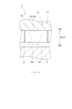
- FIG. 1 is a schematic diagram illustrating an example of a cross section perpendicular to an axial direction of a rotating machine 2 according to an embodiment of the present invention.
- 2 is a schematic diagram illustrating an example of a cross section along an axial direction of the rotary machine 2 illustrated in FIG. 1 .
- FIG. 3 is a schematic diagram for explaining the flow of a swirl in the cross section shown in FIG. 2 .
- FIG. 4 is a schematic diagram for explaining the flow of a swirl in a part of the cross section AA in FIG. 3.
- FIG. 5 is a diagram showing the relationship between the leakage flow rate and the effective damping of axial vibration of the rotor 4 for the embodiment and comparative examples 1 to 4 described with reference to FIGS.
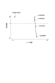
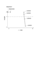
- FIG. 5 is a diagram showing the relationship between the axial position in the gap g between the outer peripheral surface 4a of the rotor 4 and the inner peripheral surface 12a of the seal main body 12 and the swirl ratio for each of the embodiments and comparative form 1 described using FIGS. 1 to 4.
- 4 is a schematic diagram illustrating another example of a cross section along the axial direction of the rotating machine 2 according to an embodiment.
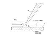
- FIG. 11 is a schematic cross-sectional view for explaining the effective cross-sectional area of the leakage flow when the stationary fin portion 18 is not inclined relative to the radial direction.
- FIG. 11 is a schematic cross-sectional view for explaining the effective cross-sectional area of the leakage flow when the stationary fin portion 18 is inclined toward the axial upstream side as it moves radially inward.
- FIG. 11 is a schematic cross-sectional view for explaining the effective cross-sectional area of the leakage flow when the stationary fin portion 18 is inclined toward the axial upstream side as it moves radially inward.
- FIG. 8 is a schematic diagram for explaining the flow of a swirl in the cross section shown in FIG. 7 .
- FIG. 8 is a diagram showing the leakage flow rate and the effective damping of the axial vibration of the rotor 4 in the embodiment shown in FIG. 7 in comparison with the comparative embodiments 1 to 4.
- 4 is a schematic diagram illustrating another example of a cross section along the axial direction of the rotating machine 2 according to an embodiment.
- expressions indicating that things are in an equal state such as “identical,””equal,” and “homogeneous,” not only indicate a state of strict equality, but also indicate a state in which there is a tolerance or a difference to the extent that the same function is obtained.
- expressions describing shapes such as a rectangular shape or a cylindrical shape do not only refer to rectangular shapes, cylindrical shapes, etc. in the strict geometric sense, but also refer to shapes that include uneven portions, chamfered portions, etc., to the extent that the same effect is obtained.
- the expressions “comprise,””include,””have,””includes,” or “have” of one element are not exclusive expressions excluding the presence of other elements.
- the rotary machine 2 may be, for example, a turbine such as a steam turbine or a compressor.
- the rotary machine 2 includes a rotor 4 and a casing 6 that houses the rotor 4.
- the casing 6 includes a casing body 8 that houses the rotor 4, and a seal device 10 (seal device for a rotary machine).
- axial direction means the axial direction of the rotor 4 unless otherwise specified
- circumferential direction means the circumferential direction of the rotor 4 unless otherwise specified
- radial direction means the radial direction of the rotor 4 unless otherwise specified.
- the upstream side in the axial direction means the upstream side of the axial flow of the fluid in the gap g between the rotor 4 and the casing 6 (the gap between the rotor 4 and the inner circumferential surface 12a of the seal body 12 described below), i.e., the high-pressure side in the axial direction in the gap g
- the downstream side in the axial direction means the downstream side of the axial flow of the fluid in the gap g, i.e., the low-pressure side in the axial direction in the gap g.
- the seal device 10 includes a seal body portion 12 and a plurality of stationary fin portions 18.
- the seal body portion 12 is formed in an annular (e.g., cylindrical) shape and is held on the inner surface 8a of the casing body 8.
- the seal body portion 12 includes an inner peripheral surface 12a, which is a stationary wall surface facing the outer peripheral surface 4a of the rotor 4, and an outer peripheral surface 12b fixed to the inner surface 8a of the casing body 8.
- a plurality of holes 16 are formed in the inner circumferential surface 12a of the seal body 12.
- the plurality of holes 16 formed in the inner circumferential surface 12a of the seal body 12 includes a plurality of holes 16 spaced apart in the circumferential direction.
- FIG. 2 is a schematic diagram showing an example of a cross section along the axial direction of the rotary machine 2 shown in FIG. 1.
- the multiple holes 16 formed in the inner circumferential surface 12a of the seal body 12 include multiple holes 16 arranged at intervals in the axial direction.
- the shape of a cross section perpendicular to the radial direction of each of the multiple holes 16 formed in the inner circumferential surface 12a of the seal body 12 may be circular. That is, in the exemplary embodiment shown in FIG. 2, each of the multiple holes 16 formed in the inner circumferential surface 12a of the seal body 12 may be a bottomed recess that forms a cylindrical cavity.
- the seal device 10 includes a plurality of stationary fin portions 18 spaced apart in the axial direction on the inner peripheral surface 12a of the seal body 12.
- Each of the stationary fin portions 18 extends circumferentially and protrudes radially inward from the inner peripheral surface 12a of the seal body 12 toward the outer peripheral surface 4a of the rotor 4.
- Each of the stationary fin portions 18 may be formed in an annular shape centered on the rotational axis of the rotor 4.
- each of the multiple stationary fin portions 18 may be provided at a position between two axially adjacent holes 16 on the inner peripheral surface 12a of the seal body portion 12.
- the holes 16 and the stationary fin portions 18 are arranged alternately in the axial direction.
- the tip portion of each of the stationary fin portions 18 may have a tapered shape (a shape in which the thickness decreases toward the radially inward direction), and in that case, the tip end surface 18t of each of the stationary fin portions 18 may include an inclined surface 18t1 that is inclined toward the axially upstream side as it moves toward the radially inward direction in order to suppress an increase in leakage flow through the gap g.
- the rotary machine 2 includes a plurality of rotor fin portions 20 (a plurality of first rotor fin portions) provided on the outer peripheral surface 4a of the rotor 4.
- Each of the plurality of rotor fin portions 20 extends along the circumferential direction and protrudes from the outer peripheral surface 4a of the rotor 4 toward the corresponding hole 16.
- each of the rotor fin portions 20 is formed at a position facing the bottom surface 16s of each hole 16, and is provided at a central position Pc of the hole 16 in the axial direction.
- FIG. 1 the exemplary embodiment shown in FIG.
- each of the rotor fin portions 20 is provided at a position between two axially adjacent stationary fin portions 18 among the plurality of stationary fin portions 18.
- the axial thickness t of each of the rotor fin portions 20 is smaller than the axial dimension w of each of the holes 16, and may satisfy, for example, t ⁇ 0.3w.
- the tip of each of the rotor fins 20 may have a tapered shape (a shape in which the thickness decreases as it moves radially outward), and in this case, the tip end surface 20t of each of the rotor fins 20 may include an inclined surface 20t1 that is inclined toward the axial upstream side as it moves radially outward, in order to suppress an increase in leakage flow from the gap g.
- the rotating machine 2 described above is provided with multiple stationary fin portions 18 and multiple rotor fin portions 20, so that the contact area between the outer peripheral surface 4a of the rotor 4 and the inner peripheral surface 12a of the seal body portion 12 when the rotor 4 is displaced in a direction perpendicular to the axial direction can be reduced compared to a case where multiple stationary fin portions 18 and multiple rotor fin portions 20 are not provided.
- This reduces the risk of contact between the rotor 4 and a stationary wall surface, i.e., the risk of thermal bending of the rotor 4 caused by frictional heat between the outer peripheral surface 4a of the rotor 4 and the inner peripheral surface 12a of the seal body portion 12.
- the swirl (leakage flow) flowing through the gap g between the outer peripheral surface 4a of the rotor 4 and the inner peripheral surface 12a of the seal body 12 is likely to flow along the rotor fin portion 20 into the hole 16 in the inner peripheral surface 12a of the seal body 12.
- arrow F2 in FIG. 4 a schematic diagram showing a part of the A-A cross section in FIG. 3
- the swirl turns within the hole 16 and becomes a reverse swirl flowing in the opposite direction to the rotation direction r of the rotor 4, and flows out of the hole 16, thereby reducing the swirl.
- the excitation force component (component in the direction perpendicular to the axial direction) of the fluid force acting on the outer peripheral surface 4a of the rotor 4 can be reduced, and the damping effect of the axial vibration of the rotor 4 can be improved, thereby achieving high axial stability of the rotor 4.
- FIG. 5 is a diagram showing the flow rate of leakage flow through the gap g (hereinafter referred to as the "leak flow rate") and the effective damping of the axial vibration of the rotor 4 for the rotary machine 2 according to the embodiment described with reference to FIGS. 1 to 4, in comparison with comparative forms 1 to 4.
- comparative form 1 corresponds to a configuration in which the plurality of stationary fin portions 18 and the plurality of rotor fin portions 20 are removed from the rotary machine 2
- comparative form 2 corresponds to a configuration in which the height of the inner peripheral surface 12a of the seal body portion 12 from the outer peripheral surface 4a of the rotor 4 is lowered compared to comparative form 1
- comparative form 3 corresponds to a configuration in which the height of the inner peripheral surface 12a of the seal body portion 12 from the outer peripheral surface 4a of the rotor 4 is lowered compared to comparative form 2
- comparative form 4 corresponds to a configuration in which the height of the inner peripheral surface 12a of the seal body portion 12 from the outer peripheral surface 4a of the rotor 4 is lowered compared to comparative form 3.
- the height of the inner circumferential surface 12a of the seal body 12 from the outer circumferential surface 4a of the rotor 4 in the above embodiment is the same as the height of the inner circumferential surface 12a of the seal body 12 from the outer circumferential surface 4a of the rotor 4 in comparative embodiment 1.
- Figure 6 shows the relationship between the axial position in the gap g between the outer circumferential surface 4a of the rotor 4 and the inner circumferential surface 12a of the seal body 12 and the non-dimensional circumferential velocity of the swirl (leakage flow) for each of the above embodiment and comparative embodiment 1.
- the non-dimensional circumferential velocity is the value obtained by dividing the circumferential velocity at each position by the circumferential velocity at the 0 mm position in the axial direction.
- the swirl ratio can be reduced in the range where the holes 16 are formed in the axial direction, compared to comparative embodiment 1, and therefore the axial vibration of the rotor 4 can be effectively damped.
- FIG. 7 is a schematic diagram showing another example of a cross section along the axial direction of a rotating machine 2 according to one embodiment.
- reference numerals common to the components shown in FIG. 2 indicate the same components as those shown in FIG. 2 unless otherwise specified, and description thereof will be omitted.
- each of the stationary fin portions 18 may be inclined toward the upstream side in the axial direction as it moves radially inward.
- each of the rotor fin portions 20 may be inclined toward the upstream side in the axial direction as it moves radially outward.
- each of the rotor fin portions 20 protrudes toward the upstream wall surface 16a1 of the inner surface 16a of the corresponding hole 16.
- each of the rotor fin portions 20 may be formed so that the line L intersects with the upstream wall surface 16a1 of the inner surface 16a of the hole 16 corresponding to the rotor fin portion 20.
- the effect of the contraction caused by each of the stationary fin portion 18 and the rotor fin portion 20 can be enhanced, and the leakage flow rate in the gap g between the outer peripheral surface 4a of the rotor 4 and the inner peripheral surface 12a of the seal body portion 12 can be effectively reduced.
- the stationary fin portion 18 is not inclined in the radial direction as shown in FIG. 8A, when the stationary fin portion 18 is inclined toward the upstream side in the axial direction as it moves toward the inside in the radial direction as shown in FIG.
- the flow is bent near the tip of the stationary fin portion 18, and the downward velocity component becomes stronger, so that the backflow area near the tip of the stationary fin portion 18 becomes larger, and the effective cross-sectional area of the leakage flow can be reduced.
- the leakage flow in the axial direction in the gap g can be redirected by the rotor fin portion 20 and circulated within the hole 16, effectively reducing the leakage flow rate.
- FIG. 9 is a diagram showing the leakage flow rate and effective damping of the axial vibration of the rotor 4 in the embodiment shown in FIG. 7, in comparison with the embodiment shown in FIG. 2 and the above-mentioned comparative forms 1 to 4.
- the embodiment shown in FIG. 7 can also achieve large effective damping while significantly reducing the leakage flow rate compared to each of the comparative forms 1 to 4, and can simultaneously reduce the risk of contact between the rotor 4 and the inner circumferential surface 12a of the seal main body 12 and increase the damping effect of the axial vibration of the rotor 4.
- the effect of reducing the leakage flow rate is even greater.
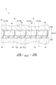
- FIG. 10 is a schematic diagram showing another example of a cross section along the axial direction of a rotating machine 2 according to one embodiment.
- reference numerals common to the components shown in FIG. 2 indicate the same components as those shown in FIG. 2 unless otherwise specified, and description thereof will be omitted.
- the multiple stationary fin portions 18 formed on the inner peripheral surface 12a of the seal body portion 12 are referred to as stationary fin portions 18a, 18b, 18c, 18d, and 18e, in order from the upstream side in the axial direction
- the multiple rotor fin portions 20 formed on the outer peripheral surface 4a of the rotor 4 are referred to as rotor fin portions 20a, 20b, 20c, and 20d, in order from the upstream side in the axial direction.
- stationary fin portion 18b is located downstream in the axial direction from stationary fin portion 18a
- stationary fin portion 18c is located downstream in the axial direction from stationary fin portion 18b
- stationary fin portion 18d is located downstream in the axial direction from stationary fin portion 18c
- stationary fin portion 18e is located downstream in the axial direction from stationary fin portion 18d.
- rotor fin portion 20a is located between stationary fin portion 18a and stationary fin portion 18b
- rotor fin portion 20b is located between stationary fin portion 18b and stationary fin portion 18c
- rotor fin portion 20c is located between stationary fin portion 18c and stationary fin portion 18d
- rotor fin portion 20d is located between stationary fin portion 18d and stationary fin portion 18e.
- the multiple holes 16 formed in the inner peripheral surface 12a of the seal body 12 include a hole 161 formed in the range between stationary fin portion 18a and stationary fin portion 18b in the axial direction, and a hole 162 formed in the range between stationary fin portion 18b and stationary fin portion 18cb in the axial direction.
- the inner peripheral surface 12a of the seal body 12 includes a hole-free region 12a1 where no hole 16 is formed between stationary fin portion 18c and stationary fin portion 18d in the axial direction, and a hole-free region 12a2 where no hole 16 is formed between stationary fin portion 18d and stationary fin portion 18e in the axial direction.
- rotor fin portion 20a is provided at the center of hole 161 in the axial direction and protrudes toward bottom surface 16s of hole 161.
- Rotor fin portion 20b is provided at the center of hole 16i in the axial direction and protrudes toward bottom surface 16s of hole 162.
- Rotor fin portion 20c is provided at the center of hole non-formation region 12a1 in the axial direction and protrudes toward hole non-formation region 12a1.
- Rotor fin portion 20d is provided at the center of hole non-formation region 12a2 in the axial direction and protrudes toward hole non-formation region 12a2.
- the distance d1 corresponds to the distance between the bottom surface 16s of the hole 161 and the rotor fin portion 20a
- the distance d2 corresponds to the distance between the bottom surface 16s of the hole 162 and the rotor fin portion 20b
- the distance d3 corresponds to the distance between the hole non-forming region 12a1 and the rotor fin portion 20c
- the distance d4 corresponds to the distance between the hole non-forming region 12a2 and the rotor fin portion 20d.
- the cross-sectional shape perpendicular to the radial direction of each of the holes 16 is circular, but the cross-sectional shape perpendicular to the radial direction of each of the holes 16 may be rectangular.
- each of the holes 16 may be a bottomed recess that forms a cavity in the shape of a rectangular prism. This can promote the turning of the flow within the hole 16 and enhance the above-described effect of reducing swirl.
- casing body 8, the seal body portion 12, and the stationary fin portion 18 do not need to be configured as separate parts, and any combination of these may be integrally configured as a single part.
- each of the multiple stationary fin portions 18 may be provided so as to straddle the multiple holes 16. In other words, when viewed in the radial direction, each of the multiple stationary fin portions 18 may be provided so as to overlap at least a portion of the multiple holes 16.
- only one of all the stationary fin portions 18 of the sealing device 10 may be provided at a position between two circumferentially adjacent holes 16 on the inner circumferential surface 12a of the seal body portion 12, or any number of all the stationary fin portions 18 of the sealing device 10 may be provided at a position between two circumferentially adjacent holes 16 on the inner circumferential surface 12a of the seal body portion 12.
- only one of all the stationary fin portions 18 of the sealing device 10 may be inclined toward the upstream side of the rotation direction r of the rotor 4 as it moves radially inward, or any number of all the stationary fin portions 18 of the sealing device 10 may be inclined toward the upstream side of the rotation direction r of the rotor 4 as it moves radially inward.
- only one of all rotor fin portions 20 of the rotary machine 2 may be inclined toward the upstream side of the rotation direction r of the rotor 4 as it moves radially outward, and any number of stationary fin portions 18 of all rotor fin portions 20 of the sealing device 10 may be inclined toward the upstream side of the rotation direction r of the rotor 4 as it moves radially outward.
- each of the multiple stationary fin portions 18 of the sealing device 10 may be inclined toward the upstream side of the rotation direction r of the rotor 4 as it moves radially inward, and each of the multiple rotor fin portions 20 may extend along the radial direction (along a plane perpendicular to the axial direction).Furthermore, each of the multiple stationary fin portions 18 of the sealing device 10 may be inclined toward the upstream side of the rotation direction r of the rotor 4 as it moves radially outward.
- a rotary machine (e.g., rotary machine 2) according to at least one embodiment of the present disclosure includes: A rotor (e.g., rotor 4); an annular seal body (e.g., seal body 12) including an inner circumferential surface (e.g., inner circumferential surface 12a) which is a stationary wall surface facing an outer circumferential surface (e.g., outer circumferential surface 4a) of the rotor, and a plurality of holes (e.g., a plurality of holes 16) formed on the inner circumferential surface; a plurality of stationary fin portions (e.g., the plurality of stationary fin portions 18) provided on the inner peripheral surface of the rotor at intervals in the axial direction of the rotor; and at least one first rotor fin portion (e.g., the plurality of rotor fin portions 20 or the rotor fin portions 20a, 20b) provided on the outer peripheral surface of the rotor.
- a rotor e.g., rot
- each of the plurality of stationary fin portions extends along a circumferential direction of the rotor and protrudes from the inner peripheral surface toward the outer peripheral surface of the rotor;
- Each of the at least one first rotor fin portion extends along the circumferential direction and protrudes from the outer circumferential surface of the rotor toward the hole.
- the rotating machine described in (1) above by providing a plurality of stationary fin portions and at least one rotor fin portion, it is possible to reduce the contact area between the outer peripheral surface of the rotor and the stationary wall surface when the rotor is displaced in a direction perpendicular to the axial direction, thereby reducing the risk of contact between the rotor and the stationary wall surface, i.e., the risk of thermal bending of the rotor due to frictional heat between the outer peripheral surface of the rotor and the stationary wall surface.
- the swirl (leakage flow) flowing in the gap between the outer circumferential surface of the rotor and the inner circumferential surface (stationary wall surface) of the seal body is more likely to flow along the rotor fins into the holes in the inner circumferential surface of the seal body, where the swirl turns inside the holes and becomes a reverse swirl flowing in the opposite direction to the rotational direction of the rotor before exiting the holes, thereby reducing the swirl and reducing the excitation force component (component perpendicular to the axial direction) of the fluid force acting on the outer circumferential surface of the rotor.
- This improves the damping effect of the rotor's axial vibration and achieves high axial stability of the rotor.
- each of the plurality of stationary fin portions is less than the dimension of the hole in the axial direction.
- the rotating machine described in (2) above can achieve high axial stability of the rotor while reducing the risk of contact between the rotor and a stationary wall surface.
- At least one of the plurality of stationary fin portions is provided at a position between two of the holes adjacent in the axial direction on the inner circumferential surface of the seal body portion.
- the stationary fin portion can be more firmly fixed to the seal body than in the case where the stationary fin portion is provided across the holes.
- the first rotor fin portion is provided at a center position of the hole in the axial direction.
- the rotating machine described in (4) above by providing the first rotor fin portion at the center position of the hole in the axial direction, a robust structure can be achieved that can suppress deterioration of sealing performance, such as a sudden decrease in effective damping or a sudden increase in leakage flow rate, even if an axial thermal expansion difference occurs between the stationary wall surface and the rotor and the axial relative position of the first rotor fin portion with respect to the hole changes.
- the shape of a cross section of the hole perpendicular to the radial direction of the rotor is rectangular.
- At least one of the plurality of stationary fin portions is inclined toward the upstream side in the axial direction as it moves toward the inside in the radial direction of the rotor.
- the rotary machine described in (7) above can enhance the effect of the contraction flow caused by the stationary fin portion, thereby reducing the amount of leakage flow that flows through the gap between the outer circumferential surface of the rotor and the stationary wall surface.
- the first rotor fin portion is inclined toward the upstream side in the axial direction as it moves toward the outside in the radial direction of the rotor.
- the rotary machine described in (8) above can enhance the contraction effect of the first rotor fin portion, thereby reducing the amount of leakage flow that flows through the gap between the outer circumferential surface of the rotor and the stationary wall surface.
- the contact area between the first rotor fin portion and the seal body portion can be reduced when the rotor is displaced in a direction perpendicular to the axial direction, thereby reducing the risk of contact between the rotor and the stationary wall surface, i.e., the risk of thermal bending of the rotor caused by frictional heat between the outer circumferential surface of the rotor and the stationary wall surface.
- the plurality of stationary fin portions include a first stationary fin portion (e.g., the above-mentioned stationary fin portion 18a or stationary fin portion 18b), a second stationary fin portion (e.g., the above-mentioned stationary fin portion 18b or stationary fin portion 18c) located downstream in the axial direction from the first stationary fin portion, a third stationary fin portion (e.g., the above-mentioned stationary fin portion 18c or stationary fin portion 18d) located downstream in the axial direction from the second stationary fin portion, and a fourth stationary fin portion (e.g., the above-mentioned stationary fin portion 18d or stationary fin portion 18e) located downstream of the third stationary fin portion,
- the plurality of holes include holes (e.g., the above-mentioned holes 161 or 162) formed in a range between the first stationary fin portion and the second stationary fin portion in the axial direction,
- the inner circumferential surface of the seal body includes a hole-
- Each of the first rotor fin portions is formed so that, in a cross section along the axial direction, a straight line connecting the base end of the first rotor fin portion and the tip of the first rotor fin portion intersects with the upstream wall surface in the axial direction on the inner surface of the hole corresponding to the first rotor fin portion.
- the axial leakage flow in the gap between the outer peripheral surface of the rotor and the inner peripheral surface of the seal body can be redirected by the first rotor fin portion and circulated within the hole, effectively reducing the flow rate of the leakage flow.
Landscapes
- Engineering & Computer Science (AREA)
- General Engineering & Computer Science (AREA)
- Mechanical Engineering (AREA)
- Sealing Using Fluids, Sealing Without Contact, And Removal Of Oil (AREA)
- Turbine Rotor Nozzle Sealing (AREA)
Abstract
Description
本願は、2023年6月16日に日本国特許庁に出願された特願2023-099099号に基づき優先権を主張し、その内容をここに援用する。
ロータと、
前記ロータの外周面に対向する静止壁面である内周面と、前記内周面に形成された複数のホールとを含む環状のシール本体部と、
前記ロータの軸方向に間隔を空けて前記内周面に設けられた複数の静止フィン部と
前記ロータの前記外周面に設けられた少なくとも1つの第1ロータフィン部と、
を備え、
前記複数の静止フィン部の各々は、前記ロータの周方向に沿って延在するとともに前記内周面から前記ロータの前記外周面に向けて突出し、
前記少なくとも1つの第1ロータフィン部の各々は、前記周方向に沿って延在するとともに前記ロータの前記外周面から前記ホールに向けて突出している。
例えば、「ある方向に」、「ある方向に沿って」、「平行」、「直交」、「中心」、「同心」或いは「同軸」等の相対的或いは絶対的な配置を表す表現は、厳密にそのような配置を表すのみならず、公差、若しくは、同じ機能が得られる程度の角度や距離をもって相対的に変位している状態も表すものとする。
例えば、「同一」、「等しい」及び「均質」等の物事が等しい状態であることを表す表現は、厳密に等しい状態を表すのみならず、公差、若しくは、同じ機能が得られる程度の差が存在している状態も表すものとする。
例えば、四角形状や円筒形状等の形状を表す表現は、幾何学的に厳密な意味での四角形状や円筒形状等の形状を表すのみならず、同じ効果が得られる範囲で、凹凸部や面取り部等を含む形状も表すものとする。
一方、一の構成要素を「備える」、「具える」、「具備する」、「含む」、又は、「有する」という表現は、他の構成要素の存在を除外する排他的な表現ではない。
図1に示すように、回転機械2は、ロータ4と、ロータ4を収容するケーシング6とを含む。ケーシング6は、ロータ4を収容するケーシング本体8と、シール装置10(回転機械用シール装置)とを備える。
ロータ(例えばロータ4)と、
前記ロータの外周面(例えば外周面4a)に対向する静止壁面である内周面(例えば内周面12a)と、前記内周面に形成された複数のホール(例えば複数のホール16)とを含む環状のシール本体部(例えばシール本体部12)と、
前記ロータの軸方向に間隔を空けて前記内周面に設けられた複数の静止フィン部(例えば上述の複数の静止フィン部18)と
前記ロータの前記外周面に設けられた少なくとも1つの第1ロータフィン部(例えば上述の複数のロータフィン部20又はロータフィン部20a,20b)と、
を備え、
前記複数の静止フィン部の各々は、前記ロータの周方向に沿って延在するとともに前記内周面から前記ロータの前記外周面に向けて突出し、
前記少なくとも1つの第1ロータフィン部の各々は、前記周方向に沿って延在するとともに前記ロータの前記外周面から前記ホールに向けて突出している。
また、ロータの外周面とシール本体部の内周面(静止壁面)との隙間を流れるスワール(漏れ流れ)がロータフィン部に沿ってシール本体部の内周面のホールに流れ込みやすくなり、スワールがホール内で転向して、ロータの回転方向と反対方向に流れる逆スワールとなってホールから流出することで、スワールを低減することができ、ロータの外周面に作用する流体力の励振力成分(軸方向と直交する方向の成分)を低減することができる。このため、ロータの軸振動の減衰効果を高めてロータの高い軸安定性を実現することができる。
前記複数の静止フィン部の各々の厚さは、前記軸方向における前記ホールの寸法よりも小さい。
前記複数の静止フィン部の少なくとも1つは、前記シール本体部の前記内周面における前記軸方向に隣り合う2つの前記ホールの間の位置に設けられる。
前記第1ロータフィン部は、前記軸方向において前記ホールの中央の位置に設けられる。
前記ホールにおける前記ロータの径方向に直交する断面の形状は円形である。
前記ホールにおける前記ロータの径方向に直交する断面の形状は四角形である。
前記複数の静止フィン部の少なくとも1つは、前記ロータの径方向における内側に向かうにつれて前記軸方向の上流側に向かうように傾斜している。
前記第1ロータフィン部は、前記ロータの径方向における外側に向かうにつれて前記軸方向の上流側に向かうように傾斜している。
前記第1ロータフィン部の先端部は先細形状を有する、請求項1に記載の回転機械。
前記複数の静止フィン部は、第1静止フィン部(例えば上述の静止フィン部18a又は静止フィン部18b)と、前記第1静止フィン部より前記軸方向における下流側に位置する第2静止フィン部(例えば上述の静止フィン部18b又は静止フィン部18c)と、前記第2静止フィン部より前記軸方向における下流側に位置する第3静止フィン部(例えば上述の静止フィン部18c又は静止フィン部18d)と、前記第3静止フィン部より下流側に位置する第4静止フィン部(例えば上述の静止フィン部18d又は静止フィン部18e)とを含み、
前記複数のホールは、前記軸方向における前記第1静止フィン部と前記第2静止フィン部との間の範囲に形成されたホール(例えば上述のホール161又はホール162)を含み、
前記シール本体部の前記内周面は、前記軸方向における前記第3静止フィン部と前記第4静止フィン部との間にホールが形成されていないホール不形成領域(例えば上述のホール不形成領域12a1又はホール不形成領域12a2)を含み、
前記回転機械は、前記軸方向における前記第3静止フィン部と前記第4静止フィン部との間の位置において前記ロータの前記外周面に設けられた第2ロータフィン部(例えば上述のロータフィン部20c又はロータフィン部20d)を含み、
前記第2ロータフィン部は前記周方向に沿って延在するとともに前記内周面の前記ホール不形成領域に向けて突出している。
前記軸方向に沿った断面において、前記第1ロータフィン部の基端と前記第1ロータフィン部の先端とを結ぶ直線と、前記第1ロータフィン部に対応する前記ホールの内面における前記軸方向の上流側の壁面とが交差するように、前記第1ロータフィン部の各々が形成される。
4 ロータ
4a 外周面
6 ケーシング
8 ケーシング本体
8a 内面
10 シール装置
12 シール本体部
12a 内周面
12a1,12a2 ホール不形成領域
12b 外周面
16 ホール
16a 内面
16a1 壁面
16s 底面
18,18a,18b,18c,18d,18e 静止フィン部
20,20a,20b,20c,20d ロータフィン部
L 直線
Pc 位置
d1,d2,d3,d4 距離
g 隙間
r 回転方向
w 寸法
Claims (11)
- ロータと、
前記ロータの外周面に対向する静止壁面である内周面と、前記内周面に形成された複数のホールとを含む環状のシール本体部と、
前記ロータの軸方向に間隔を空けて前記内周面に設けられた複数の静止フィン部と
前記ロータの前記外周面に設けられた少なくとも1つの第1ロータフィン部と、
を備え、
前記複数の静止フィン部の各々は、前記ロータの周方向に沿って延在するとともに前記内周面から前記ロータの前記外周面に向けて突出し、
前記少なくとも1つの第1ロータフィン部の各々は、前記周方向に沿って延在するとともに前記ロータの前記外周面から前記ホールに向けて突出に向けて突出している、回転機械。 - 前記複数の静止フィン部の各々の厚さは、前記軸方向における前記ホールの寸法よりも小さい、請求項1に記載の回転機械。
- 前記複数の静止フィン部の少なくとも1つは、前記シール本体部の前記内周面における前記軸方向に隣り合う2つの前記ホールの間の位置に設けられた、請求項1に記載の回転機械。
- 前記第1ロータフィン部は、前記軸方向における前記ホールの中央の位置に設けられた、請求項1に記載の回転機械。
- 前記ホールにおける前記ロータの径方向に直交する断面の形状は円形である、請求項1に記載の回転機械。
- 前記ホールにおける前記ロータの径方向に直交する断面の形状は四角形である、請求項1に記載の回転機械。
- 前記複数の静止フィン部の少なくとも1つは、前記ロータの径方向における内側に向かうにつれて前記軸方向の上流側に向かうように傾斜している、請求項1に記載の回転機械。
- 前記第1ロータフィン部は、前記ロータの径方向における外側に向かうにつれて前記軸方向の上流側に向かうように傾斜している、請求項1に記載の回転機械。
- 前記第1ロータフィン部の先端部は先細形状を有する、請求項1に記載の回転機械。
- 前記複数の静止フィン部は、第1静止フィン部と、前記第1静止フィン部より前記軸方向における下流側に位置する第2静止フィン部と、前記第2静止フィン部より前記軸方向における下流側に位置する第3静止フィン部と、前記第3静止フィン部より下流側に位置する第4静止フィン部とを含み、
前記複数のホールは、前記軸方向における前記第1静止フィン部と前記第2静止フィン部との間の範囲に形成されたホールを含み、
前記シール本体部の前記内周面は、前記軸方向における前記第3静止フィン部と前記第4静止フィン部との間にホールが形成されていないホール不形成領域を含み、
前記回転機械は、前記軸方向における前記第3静止フィン部と前記第4静止フィン部との間の位置において前記ロータの前記外周面に設けられた第2ロータフィン部を含み、
前記第2ロータフィン部は前記周方向に沿って延在するとともに前記内周面の前記ホール不形成領域に向けて突出している、請求項1に記載の回転機械。 - 前記軸方向に沿った断面において、前記第1ロータフィン部の基端と前記第1ロータフィン部の先端とを結ぶ直線と、前記第1ロータフィン部に対応する前記ホールの内面における前記軸方向の上流側の壁面とが交差するように、前記第1ロータフィン部の各々が形成された、請求項1に記載の回転機械。
Priority Applications (4)
| Application Number | Priority Date | Filing Date | Title |
|---|---|---|---|
| DE112024001577.8T DE112024001577T5 (de) | 2023-06-16 | 2024-06-05 | Drehmaschine |
| CN202480032630.9A CN121127682A (zh) | 2023-06-16 | 2024-06-05 | 旋转机械 |
| KR1020257036744A KR20250170098A (ko) | 2023-06-16 | 2024-06-05 | 회전 기계 |
| JP2025527860A JPWO2024257664A1 (ja) | 2023-06-16 | 2024-06-05 |
Applications Claiming Priority (2)
| Application Number | Priority Date | Filing Date | Title |
|---|---|---|---|
| JP2023099099 | 2023-06-16 | ||
| JP2023-099099 | 2023-06-16 |
Publications (1)
| Publication Number | Publication Date |
|---|---|
| WO2024257664A1 true WO2024257664A1 (ja) | 2024-12-19 |
Family
ID=93851921
Family Applications (1)
| Application Number | Title | Priority Date | Filing Date |
|---|---|---|---|
| PCT/JP2024/020502 Ceased WO2024257664A1 (ja) | 2023-06-16 | 2024-06-05 | 回転機械 |
Country Status (5)
| Country | Link |
|---|---|
| JP (1) | JPWO2024257664A1 (ja) |
| KR (1) | KR20250170098A (ja) |
| CN (1) | CN121127682A (ja) |
| DE (1) | DE112024001577T5 (ja) |
| WO (1) | WO2024257664A1 (ja) |
Citations (2)
| Publication number | Priority date | Publication date | Assignee | Title |
|---|---|---|---|---|
| JP2016153654A (ja) * | 2012-11-13 | 2016-08-25 | 三菱重工コンプレッサ株式会社 | 回転機械 |
| JP2018063006A (ja) * | 2016-10-13 | 2018-04-19 | 株式会社神戸製鋼所 | ラビリンスシール |
Family Cites Families (1)
| Publication number | Priority date | Publication date | Assignee | Title |
|---|---|---|---|---|
| JP7502934B2 (ja) | 2020-08-27 | 2024-06-19 | 三協立山株式会社 | バリアフリー化建具およびバリアフリー化建具の製造方法 |
-
2024
- 2024-06-05 DE DE112024001577.8T patent/DE112024001577T5/de active Pending
- 2024-06-05 CN CN202480032630.9A patent/CN121127682A/zh active Pending
- 2024-06-05 KR KR1020257036744A patent/KR20250170098A/ko active Pending
- 2024-06-05 WO PCT/JP2024/020502 patent/WO2024257664A1/ja not_active Ceased
- 2024-06-05 JP JP2025527860A patent/JPWO2024257664A1/ja active Pending
Patent Citations (2)
| Publication number | Priority date | Publication date | Assignee | Title |
|---|---|---|---|---|
| JP2016153654A (ja) * | 2012-11-13 | 2016-08-25 | 三菱重工コンプレッサ株式会社 | 回転機械 |
| JP2018063006A (ja) * | 2016-10-13 | 2018-04-19 | 株式会社神戸製鋼所 | ラビリンスシール |
Also Published As
| Publication number | Publication date |
|---|---|
| DE112024001577T5 (de) | 2026-03-26 |
| KR20250170098A (ko) | 2025-12-04 |
| JPWO2024257664A1 (ja) | 2024-12-19 |
| CN121127682A (zh) | 2025-12-12 |
Similar Documents
| Publication | Publication Date | Title |
|---|---|---|
| CN109812493B (zh) | 空气箔片径向轴承 | |
| CN104471293B (zh) | 具有螺旋形式或螺旋‑圆筒形混合形式的高阻尼迷宫密封件 | |
| JP2008008490A (ja) | セグメント間の「l」字形突合せギャップシールを備えるシール組立体及び回転機械 | |
| CN104520540B (zh) | 轴流式流体机械 | |
| JP2012041923A (ja) | タービンエンジンシール | |
| US11111956B2 (en) | Squeeze film damper bearing and rotary machine including the same | |
| WO2015115558A1 (ja) | シール構造、及び回転機械 | |
| WO2014091599A1 (ja) | 回転流体機械 | |
| WO2014077058A1 (ja) | 回転機械 | |
| US10808752B2 (en) | Sliding members | |
| JP5643245B2 (ja) | ターボ機械 | |
| JP2019157662A (ja) | 動翼側シール装置、静翼側シール装置及び回転機械 | |
| AU2019339800B2 (en) | Damper bearing and damper | |
| JP7258050B2 (ja) | 軸受装置及びこれを備えたターボチャージャ | |
| JP2005214144A (ja) | 流体機械の旋回流防止装置 | |
| CN108699915B (zh) | 密封构造及涡轮机械 | |
| JP2010116944A (ja) | 浮動ブッシュ軸受式の軸受装置及びこれを備える内燃機関の過給機 | |
| JP2018135847A (ja) | 軸流回転機械 | |
| KR20250170098A (ko) | 회전 기계 | |
| JP2025001496A (ja) | 回転機械用シール装置及び回転機械 | |
| WO2019087890A1 (ja) | ティルティングパッド軸受 | |
| JP6088029B2 (ja) | シール装置 | |
| JP7445495B2 (ja) | ラビリンスシール及びガスタービン | |
| JP7519201B2 (ja) | ラビリンスシール及びガスタービン | |
| US11719124B2 (en) | Turbocharger |
Legal Events
| Date | Code | Title | Description |
|---|---|---|---|
| 121 | Ep: the epo has been informed by wipo that ep was designated in this application |
Ref document number: 24823283 Country of ref document: EP Kind code of ref document: A1 |
|
| ENP | Entry into the national phase |
Ref document number: 1020257036744 Country of ref document: KR Free format text: ST27 STATUS EVENT CODE: A-0-1-A10-A15-NAP-PA0105 (AS PROVIDED BY THE NATIONAL OFFICE) |
|
| WWE | Wipo information: entry into national phase |
Ref document number: KR1020257036744 Country of ref document: KR |
|
| ENP | Entry into the national phase |
Ref document number: 2025527860 Country of ref document: JP Kind code of ref document: A |
|
| WWE | Wipo information: entry into national phase |
Ref document number: 202517109595 Country of ref document: IN |
|
| WWE | Wipo information: entry into national phase |
Ref document number: 112024001577 Country of ref document: DE |
|
| WWP | Wipo information: published in national office |
Ref document number: 202517109595 Country of ref document: IN |
|
| WWP | Wipo information: published in national office |
Ref document number: 112024001577 Country of ref document: DE |