WO2024257596A1 - 車載中継装置、中継方法および中継プログラム - Google Patents
車載中継装置、中継方法および中継プログラム Download PDFInfo
- Publication number
- WO2024257596A1 WO2024257596A1 PCT/JP2024/019433 JP2024019433W WO2024257596A1 WO 2024257596 A1 WO2024257596 A1 WO 2024257596A1 JP 2024019433 W JP2024019433 W JP 2024019433W WO 2024257596 A1 WO2024257596 A1 WO 2024257596A1
- Authority
- WO
- WIPO (PCT)
- Prior art keywords
- unit
- vehicle
- packet
- relay device
- data size
- Prior art date
- Legal status (The legal status is an assumption and is not a legal conclusion. Google has not performed a legal analysis and makes no representation as to the accuracy of the status listed.)
- Ceased
Links
Images



Classifications
-
- B—PERFORMING OPERATIONS; TRANSPORTING
- B60—VEHICLES IN GENERAL
- B60R—VEHICLES, VEHICLE FITTINGS, OR VEHICLE PARTS, NOT OTHERWISE PROVIDED FOR
- B60R16/00—Electric or fluid circuits specially adapted for vehicles and not otherwise provided for; Arrangement of elements of electric or fluid circuits specially adapted for vehicles and not otherwise provided for
- B60R16/02—Electric or fluid circuits specially adapted for vehicles and not otherwise provided for; Arrangement of elements of electric or fluid circuits specially adapted for vehicles and not otherwise provided for electric constitutive elements
- B60R16/023—Electric or fluid circuits specially adapted for vehicles and not otherwise provided for; Arrangement of elements of electric or fluid circuits specially adapted for vehicles and not otherwise provided for electric constitutive elements for transmission of signals between vehicle parts or subsystems
-
- H—ELECTRICITY
- H04—ELECTRIC COMMUNICATION TECHNIQUE
- H04L—TRANSMISSION OF DIGITAL INFORMATION, e.g. TELEGRAPHIC COMMUNICATION
- H04L12/00—Data switching networks
- H04L12/28—Data switching networks characterised by path configuration, e.g. LAN [Local Area Networks] or WAN [Wide Area Networks]
-
- H—ELECTRICITY
- H04—ELECTRIC COMMUNICATION TECHNIQUE
- H04L—TRANSMISSION OF DIGITAL INFORMATION, e.g. TELEGRAPHIC COMMUNICATION
- H04L12/00—Data switching networks
- H04L12/28—Data switching networks characterised by path configuration, e.g. LAN [Local Area Networks] or WAN [Wide Area Networks]
- H04L12/46—Interconnection of networks
Definitions
- the present disclosure relates to an in-vehicle relay device, a relay method, and a relay program.
- This application claims priority based on Japanese Patent Application No. 2023-99499, filed on June 16, 2023, the disclosure of which is incorporated herein in its entirety.
- Patent Document 1 JP Patent Publication 2015-147446A discloses the following vehicle control device. That is, the vehicle control device has a plurality of unit vehicle control devices mounted on a vehicle and connected via a network, and a vehicle identification code for identifying the vehicle is stored in at least one unit vehicle control device. Each of the unit vehicle control devices has a node that exchanges messages with an external diagnostic device via communication, and one of the nodes is a representative node, and the unique identification information held by the representative node is transferred to and stored in other nodes as vehicle identification information.
- each of the nodes In response to a vehicle identification request message sent from the diagnostic device to each of the nodes, each of the nodes replies with either a vehicle identification response message including the vehicle identification code and the vehicle identification information stored in each node itself, or a vehicle identification response message including the vehicle identification information stored in each node itself without the vehicle identification code.
- the vehicle-mounted relay device disclosed herein is an in-vehicle relay device that relays packets transmitted and received between functional units, and includes a setting unit that sets a window size, which is the maximum data size of the packet that the source functional unit, which is the functional unit that sent the packet, can send to the vehicle-mounted relay device, and which is notified to the source functional unit when a communication connection between the source functional unit and the vehicle-mounted relay device is established, and a communication unit that notifies the source functional unit of the window size set by the setting unit, and when the communication unit receives the packet from the source functional unit after notifying the window size, performs a response process in which a response packet for the received packet is sent to the source functional unit including control information for controlling a requested data size, which is the data size of the packet that the source functional unit is requested to send, and the setting unit sets the window size to a value larger than the requested data size.
- One aspect of the present disclosure can be realized not only as an in-vehicle relay device equipped with such a characteristic processing unit, but also as a semiconductor integrated circuit that realizes part or all of the in-vehicle relay device, or as a system that includes the in-vehicle relay device.
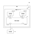
- FIG. 1 is a diagram illustrating a configuration of a communication system according to a first embodiment of the present disclosure.
- FIG. 2 is a diagram illustrating an example of an IP packet transmitted and received between the vehicle-mounted relay device according to the first embodiment of the present disclosure and the diagnostic device.
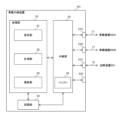
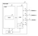
- FIG. 3 is a diagram illustrating a configuration of an in-vehicle relay device according to the first embodiment of the present disclosure.
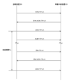
- FIG. 4 is a diagram showing an example of a processing sequence of a diagnostic device and an in-vehicle relay device in a communication system of a comparative example.
- FIG. 5 is a diagram illustrating an example of a correspondence table stored by the vehicle-mounted relay device according to the first embodiment of the present disclosure.
- FIG. 1 is a diagram illustrating a configuration of a communication system according to a first embodiment of the present disclosure.
- FIG. 2 is a diagram illustrating an example of an IP packet transmitted and received between the vehicle-mounted relay device according to the first embodiment of the present disclosure and the diagnostic device.
- FIG. 6 is a sequence illustrating an example of processing of the diagnostic device and the vehicle-mounted relay device in the communication system according to the first embodiment of the present disclosure.
- FIG. 7 is a sequence diagram illustrating another example of the processing of the diagnostic device and the vehicle-mounted relay device in the communication system according to the first embodiment of the present disclosure.
- FIG. 8 is a diagram illustrating an example of an updated correspondence table stored in the vehicle-mounted relay device according to the first embodiment of the present disclosure.
- FIG. 9 is a flowchart defining an operation procedure when the vehicle-mounted relay device according to the first embodiment of the present disclosure performs the setting process and the response process.
- FIG. 10 is a diagram illustrating a configuration of a modified example of the communication system according to the first embodiment of the present disclosure.
- FIG. 11 is a diagram illustrating a configuration of a modified example of the vehicle-mounted relay device according to the first embodiment of the present disclosure.
- FIG. 12 is a diagram illustrating an example of an updated correspondence table stored in the modified example of the vehicle-mounted relay device according to the first embodiment of the present disclosure.
- FIG. 13 is a diagram illustrating a configuration of an in-vehicle relay device according to the second embodiment of the present disclosure.
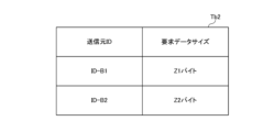
- FIG. 14 is a diagram illustrating an example of a correspondence table stored by the vehicle-mounted relay device according to the second embodiment of the present disclosure.
- FIG. 15 is a flowchart defining an operation procedure when the vehicle-mounted relay device according to the second embodiment of the present disclosure performs the setting process and the response process.
- vehicle-mounted relay devices have been developed that relay packets sent and received between functional units.
- the present disclosure has been made to solve the above-mentioned problems, and its purpose is to provide an in-vehicle relay device, a relay method, and a relay program that can achieve stable throughput in packet transmission in an in-vehicle network.
- a stable throughput can be achieved in packet transmission in an in-vehicle network.
- An in-vehicle relay device is an in-vehicle relay device that relays packets transmitted and received between functional units, and includes a setting unit that sets a window size, which is the maximum data size of the packet that a source functional unit, which is the functional unit from which the packet is sent, can send to the in-vehicle relay device, and which is to be notified to the source functional unit when a communication connection between the source functional unit and the in-vehicle relay device is established, and a communication unit that notifies the source functional unit of the window size set by the setting unit, wherein when the communication unit receives the packet from the source functional unit after notifying the window size, the communication unit performs a response process in which a response packet for the received packet is sent to the source functional unit including control information for controlling a requested data size, which is the data size of the packet that the source functional unit is requested
- the functional unit when a communication connection is established with the functional unit that is the source of a packet, the functional unit is notified of a window size larger than the requested data size notified in the response process.
- This makes it possible to receive a larger number of packets per unit time than the number of packets to be sent to the destination functional unit, so that already received packets can be sent to the destination functional unit during the period until the requested new packets arrive from the source functional unit. This makes it possible to achieve stable throughput in packet transmission.
- This configuration makes it possible to adjust the request data size notified to the source functional unit according to the target throughput value between the vehicle-mounted relay device and the destination functional unit, thereby stabilizing the throughput and bringing it closer to the target value.
- the setting unit may perform a calculation process to calculate the requested data size based on a round-trip time from when the communication unit transmits the response packet to when the communication unit receives the packet in response to the response packet, and the communication unit may notify the source function unit of the control information for controlling the requested data size calculated by the setting unit in the response process.
- the requested data size notified to the source functional unit can be adjusted according to the round-trip time of the packet between the in-vehicle relay device and the source functional unit, so that the requested data size that takes into account the length of the round-trip time can be notified to the source functional unit.
- the vehicle-mounted relay device may include a measurement unit that measures the round-trip time, and the setting unit may calculate the requested data size in the calculation process based on the round-trip time measured by the measurement unit.
- This configuration allows the source functional unit to be notified of the requested data size based on the actual measured round trip time, making it possible to notify the source functional unit of a more accurate requested data size according to the load status of the in-vehicle network.
- the communication unit may communicate with a plurality of the source function units
- the vehicle relay device may further include a round-trip time determination unit that determines the round-trip time depending on the source function unit
- the setting unit may calculate the requested data size in the calculation process based on the round-trip time determined by the round-trip time determination unit.
- This configuration makes it possible to notify the appropriate requested data size according to the round-trip time for each source functional unit, thereby achieving a more stable throughput when packets from each source functional unit are sent to the destination functional unit.
- the communication unit may communicate with a plurality of the source function units, and when the packet is received by the communication unit, the setting unit may determine the requested data size depending on the source function unit, and the communication unit may notify the source function unit of the control information for controlling the requested data size determined by the setting unit in the response process.
- This configuration allows each source functional unit to be notified of the appropriate requested data size, making it possible to achieve more stable throughput when packets from each source functional unit are sent to the destination functional unit.
- the communication unit notifies the source function unit of the acknowledgement number included in the response packet as the control information in the response process.
- This configuration allows the requested data size to be notified to the sending functional unit through simple processing that uses the existing acknowledgment number.
- the source function unit may be provided outside the vehicle network including the vehicle relay device and connected to the vehicle relay device via a LAN cable, and the communication unit may relay the packet to the function unit provided in the vehicle network.
- This configuration makes it possible to achieve stable throughput in packet transmissions in the in-vehicle network to which the diagnostic device is connected, for example when diagnosing vehicle faults.
- a relay method is a relay method in an in-vehicle relay device that relays packets transmitted and received between functional units, and includes the steps of: setting a window size, which is a data size equivalent to the maximum number of packets per unit time that a source functional unit, which is the functional unit from which the packets are transmitted, can transmit to the in-vehicle relay device, and which is to be notified to the source functional unit when a communication connection between the source functional unit and the in-vehicle relay device is established; notifying the source functional unit of the set window size; and performing a response process in which, when the packet is received from the source functional unit after notifying the window size, a response packet for the received packet is sent to the source functional unit including control information for controlling a requested data size, which is a data size equivalent to the number of packets per unit time that the source functional unit is requested to transmit, and in the step of setting the window size, the window size is set to a value larger than the requested data size.
- the functional unit when a communication connection is established with the functional unit that is the source of a packet, the functional unit is notified of a window size larger than the requested data size notified in the response process.
- This makes it possible to receive a larger number of packets per unit time than the number of packets to be sent to the destination functional unit, so that already received packets can be sent to the destination functional unit during the period until the requested new packets arrive from the source functional unit. This makes it possible to achieve stable throughput in packet transmission.
- a relay program is a relay program used in an in-vehicle relay device that relays packets transmitted and received between functional units, and causes a computer to function as a setting unit that sets a window size, which is the maximum data size of the packet that a source functional unit, which is the functional unit that transmits the packet, can transmit to the in-vehicle relay device, and which is notified to the source functional unit when a communication connection between the source functional unit and the in-vehicle relay device is established, and a communication unit that notifies the source functional unit of the window size set by the setting unit, and when the communication unit receives the packet from the source functional unit after notifying the window size, performs a response process in which a response packet for the received packet is transmitted to the source functional unit including control information for controlling a requested data size, which is the data size of the packet that the source functional unit is requested to transmit, and the setting unit sets the window size to a value larger than the requested data size.
- the functional unit when a communication connection is established with the functional unit that is the source of a packet, the functional unit is notified of a window size larger than the requested data size notified in the response process.
- This makes it possible to receive a larger number of packets per unit time than the number of packets to be sent to the destination functional unit, so that already received packets can be sent to the destination functional unit during the period until the requested new packets arrive from the source functional unit. This makes it possible to achieve stable throughput in packet transmission.
- Fig. 1 is a diagram showing a configuration of a communication system according to a first embodiment of the present disclosure.
- a communication system 501 includes an in-vehicle system 301 and a diagnostic device 201.
- the in-vehicle system 301 is mounted on a vehicle 1.
- the diagnostic device 201 is a diagnostic tool that complies with, for example, DoIP (Diagnostics over Internet Protocol), which is a communication standard defined in ISO13400, and performs a fault diagnosis of the in-vehicle system 301.
- DoIP Diagnostics over Internet Protocol
- the diagnostic device 201 is an example of a functional unit.
- the in-vehicle system 301 includes an in-vehicle relay device 101 and multiple in-vehicle devices 202.
- the in-vehicle devices 202 are an example of a functional unit.
- the in-vehicle devices 202 include an autonomous driving ECU (Electronic Control Unit), an engine ECU, a body control ECU, a TCU (Telematics Communication Unit), sensors, a navigation device, a human-machine interface, and a camera.
- ECU Electronic Control Unit
- engine ECU Engine Control Unit
- body control ECU body control ECU
- TCU Telematics Communication Unit
- sensors a navigation device
- human-machine interface a camera.
- the in-vehicle system 301 includes in-vehicle devices 202A and 202B that are in-vehicle devices 202.
- the in-vehicle relay device 101 and the multiple in-vehicle devices 202 form an in-vehicle network 401.
- the in-vehicle system 301 is not limited to a configuration having two in-vehicle devices 202, but may be a configuration having one or three or more in-vehicle devices 202.
- the in-vehicle relay device 101 is, for example, a gateway device.
- the in-vehicle relay device 101 can relay data between multiple in-vehicle devices 202 connected to it.
- Each in-vehicle device 202 is connected to the in-vehicle relay device 101 via, for example, an Ethernet (registered trademark) cable 11.
- the vehicle-mounted relay device 101 has multiple communication ports 51.
- the communication ports 51A, 51B, and 51C are terminals to which an Ethernet cable 11 can be connected, for example.
- the vehicle-mounted devices 202A and 202B are connected to the communication ports 51A and 51B, respectively, via the Ethernet cable 11.
- the in-vehicle relay device 101 is not limited to being connected to the in-vehicle device 202 via an Ethernet cable 11, but may be connected to the in-vehicle device 202 via a bus conforming to standards such as CAN (Controller Area Network), CAN FD (CAN with Flexible Data Rate), FlexRay (registered trademark), MOST (Media Oriented System Transport) (registered trademark), LIN (Local Interconnect Network), and CXPI (Clock Extension Peripheral Interface) (registered trademark).
- CAN Controller Area Network
- CAN FD CAN with Flexible Data Rate
- FlexRay registered trademark
- MOST Media Oriented System Transport
- LIN Local Interconnect Network
- CXPI Chip Extension Peripheral Interface
- the vehicle-mounted relay device 101 can also relay data between the diagnostic device 201 and the vehicle-mounted device 202 connected to it.
- the diagnostic device 201 is provided outside the vehicle network 401 including the vehicle relay device 101, and is connected to the vehicle relay device 101 via a LAN (Local Area Network) cable 12 such as an Ethernet cable.
- LAN Local Area Network
- the communication port 51D which is the communication port 51 in the vehicle-mounted relay device 101, is, for example, a terminal to which the LAN cable 12 can be connected.
- the diagnostic device 201 is connected to the communication port 51D via the LAN cable 12.
- vehicle relay device 101 is not limited to a configuration having four communication ports 51, but may be a configuration having two, three, or five or more communication ports 51.
- IP packets are stored in Ethernet frames and transmitted.
- the diagnostic device 201 transmits and receives IP packets including messages to and from the vehicle-mounted relay device 101 by establishing a communication connection for exchanging predetermined messages according to a connection-based protocol.
- FIG. 2 is a diagram showing an example of an IP packet transmitted and received between an in-vehicle relay device and a diagnostic device according to the first embodiment of the present disclosure.
- the diagnostic device 201 and the in-vehicle relay device 101 transmit and receive IP packets according to TCP (Transmission Control Protocol)/IP.
- TCP Transmission Control Protocol
- the diagnostic device 201 and the in-vehicle relay device 101 establish a TCP connection, which is a communication connection that complies with TCP/IP, by a three-way handshake.
- the diagnostic device 201 creates an IP packet (hereinafter also referred to as a "SYN packet") that includes a TCP packet in which the SYN (synchronize) flag in the TCP header is set to on, and transmits the created SYN packet to the vehicle-mounted relay device 101.
- SYN packet an IP packet
- TCP packet in which the SYN (synchronize) flag in the TCP header is set to on
- the in-vehicle relay device 101 When the in-vehicle relay device 101 receives a SYN packet from the diagnostic device 201, it creates an IP packet (hereinafter also referred to as a "SYN/ACK packet") including a TCP packet with the SYN flag and ACK (acknowledgement) flag in the TCP header set to on, and transmits the IP packet including the created SYN/ACK packet to the diagnostic device 201.
- SYN/ACK packet IP packet including a TCP packet with the SYN flag and ACK (acknowledgement) flag in the TCP header set to on
- the diagnostic device 201 When the diagnostic device 201 receives a SYN/ACK packet from the vehicle-mounted relay device 101, it creates an IP packet (hereinafter also referred to as an "ACK packet") including a TCP packet with the ACK flag in the TCP header set to ON, and transmits the created ACK packet to the vehicle-mounted relay device 101. This establishes a TCP connection between the diagnostic device 201 and the vehicle-mounted relay device 101.
- ACK packet IP packet
- the diagnostic device 201 when the diagnostic device 201 terminates the TCP connection with the vehicle-mounted relay device 101, it creates an IP packet (hereinafter also referred to as a "FIN packet") that includes a TCP packet with the FIN (finish) flag in the TCP header set to on, and transmits the created FIN packet to the vehicle-mounted relay device 101.
- FIN packet IP packet
- the in-vehicle relay device 101 When the in-vehicle relay device 101 receives a FIN packet from the diagnostic device 201, it creates an IP packet (hereinafter also referred to as a "FIN/ACK packet") that includes a TCP packet in which the FIN flag and the ACK flag in the TCP header are set to ON, and transmits the created FIN/ACK packet to the diagnostic device 201.
- FIN/ACK packet an IP packet
- the diagnostic device 201 When the diagnostic device 201 receives the FIN/ACK packet from the in-vehicle relay device 101, it creates an ACK packet and transmits the created ACK packet to the in-vehicle relay device 101. This ends the TCP connection between the diagnostic device 201 and the in-vehicle relay device 101.
- the diagnostic device 201 transmits one or more IP packets to the destination in-vehicle device 202 via the in-vehicle relay device 101.
- diagnostic device 201 creates an IP packet (hereinafter also referred to as a "DoIP packet") that includes a message conforming to the DoIP standard and includes its own IP address and the IP address of the destination in-vehicle device 202 as the source IP address and destination IP address, respectively. Then, diagnostic device 201 transmits the created DoIP packet to the destination in-vehicle device 202 via in-vehicle relay device 101.
- DoIP packet an IP packet that includes a message conforming to the DoIP standard and includes its own IP address and the IP address of the destination in-vehicle device 202 as the source IP address and destination IP address, respectively.
- the in-vehicle relay device 101 includes a plurality of communication ports 51, a relay unit 52, a processing unit 53, and a storage unit 54.
- the relay unit 52 includes a buffer 55.
- the processing unit 53 includes a setting unit 61, a measurement unit 62, and an update unit 63.
- One or both of the relay unit 52 and the processing unit 53 are realized, for example, by a processing circuit (Circuitry) including one or more processors.
- the storage unit 54 is, for example, a non-volatile memory included in the processing circuit.
- the relay unit 52 is an example of a communication unit.
- the relay unit 52 performs relay processing to relay data transmitted and received between devices connected to its own vehicle-mounted relay device 101.
- the relay unit 52 can perform relay processing according to, for example, layer 2 and layer 3, which is higher than layer 2.
- the relay unit 52 relays IP packets transmitted and received between the in-vehicle devices 202.
- the relay unit 52 receives an IP packet from a certain in-vehicle device 202, it transmits the received IP packet to the destination in-vehicle device 202.
- the relay unit 52 also performs packet relay processing to relay IP packets transmitted and received between the diagnostic device 201 and the in-vehicle device 202.
- the relay unit 52 when the relay unit 52 receives a DoIP packet from the diagnostic device 201, it stores the received DoIP packet in the buffer 55 and performs a conversion process to convert the destination IP address included in the received DoIP packet.
- the storage unit 54 stores an ARP (Address Resolution Protocol) table that indicates the correspondence between IP addresses and MAC (Media Access Control) addresses.
- ARP Address Resolution Protocol
- the relay unit 52 When the relay unit 52 receives a DoIP packet from the diagnostic device 201, it refers to the ARP table in the storage unit 54 to identify the MAC address that corresponds to the destination IP address included in the DoIP packet as the destination MAC address.
- the storage unit 54 further stores an address table Tb10 that indicates the correspondence between destination MAC addresses and communication ports.
- the relay unit 52 When the relay unit 52 identifies the destination MAC address, it identifies the communication port 51 that corresponds to the destination MAC address by referring to the address table Tb10 in the storage unit 54. Then, the relay unit 52 transmits the DoIP packet stored in the buffer 55 from the identified communication port 51 to the relay destination in-vehicle device 202.
- the in-vehicle device 202 When the in-vehicle device 202 receives a DoIP packet from the in-vehicle relay device 111, it performs a predetermined process based on the received DoIP packet. For example, if the DoIP packet contains a message requesting the acquisition of data necessary for the diagnostic device 201 to perform a fault diagnosis, the in-vehicle device 202 acquires the data.
- [Problem Description] 4 is a diagram showing an example of a sequence of processes of a diagnostic device and an in-vehicle relay device in a communication system according to a comparative example.
- DoIP packets transmitted in the communication system according to the comparative example are indicated by white rectangles.
- the diagnostic device 211 which is a comparative diagnostic device, transmits one DoIP packet to the vehicle-mounted relay device 111 (step S2) while a communication connection is established with the vehicle-mounted relay device 111, which is a comparative vehicle-mounted relay device (step S1).
- the in-vehicle relay device 111 performs a conversion process on the DoIP packet received from the diagnostic device 211, and transmits the converted DoIP packet to the in-vehicle device 202 (step S3).
- the in-vehicle repeater 111 transmits to the diagnostic device 211 a transmission request packet, which is an IP packet requesting the diagnostic device 211 to transmit a DoIP packet, in accordance with DoIP.
- the in-vehicle repeater 111 transmits to the diagnostic device 211 a transmission request packet requesting the transmission of one DoIP packet (step S4).
- the diagnostic device 211 receives a transmission request packet from the vehicle-mounted relay device 111, it transmits one DoIP packet to the vehicle-mounted relay device 111 (step S5).
- step S6 the processes from step S3 to step S5 are repeated in the same manner. Then, the diagnostic device 211 and the in-vehicle relay device 111 terminate the TCP connection (step S6).
- the vehicle-mounted relay device 111 waits from sending a transmission request packet to the diagnosis device 211 until it receives a DoIP packet from the diagnosis device 211. That is, in the communication system of the comparative example, the period from when the vehicle-mounted relay device 111 sends a transmission request packet to the diagnosis device 211 until it receives the DoIP packet from the diagnosis device 211 is an idle time during which the vehicle-mounted relay device 111 is not performing packet relay processing or conversion processing. Therefore, in the communication system of the comparative example, the throughput between the diagnosis device 211 and the vehicle-mounted relay device 111 is reduced and unstable due to this idle time.
- the vehicle-mounted relay device 101 solves the above problem by adopting the following configuration and operation.
- the setting unit 61 in the vehicle-mounted relay device 101 sets a maximum value M of the number of DoIP packets per unit time that a source functional unit of a packet (hereinafter also referred to as a "source functional unit”) can transmit to the vehicle-mounted relay device 101. More specifically, the setting unit 61 performs a setting process to set the maximum value M to be notified to the source functional unit when a communication connection is established between the source functional unit and the vehicle-mounted relay device 101. The relay unit 52 notifies the source functional unit of the maximum value M set by the setting unit 61.
- the source functional unit will be described as the diagnostic device 201 shown in FIG. 1.
- the relay unit 52 transmits and receives packets to and from the diagnostic device 201 in accordance with the above-mentioned TCP/IP.
- the setting unit 61 monitors packets received by the relay unit 52 and checks the contents of the packets by referencing the TCP headers of the packets.
- the setting unit 61 determines that a communication connection between the diagnostic device 201 and its own vehicle-mounted relay device 101 has been established.
- the relay unit 52 when the relay unit 52 receives a DoIP packet from the diagnostic device 201, it performs a response process of transmitting a response packet P2 to the diagnostic device 201 in response to the DoIP packet.
- the response packet P2 includes the total value of the data size of the DoIP packets that the diagnostic device 201 is requested to transmit (hereinafter, also referred to as the "requested data size Dr").
- the relay unit 52 includes in the response packet P2 the number of DoIP packets per unit time (hereinafter also referred to as the "number of requested packets Nr") that corresponds to the requested data size Dr.
- the setting unit 61 determines that a communication connection between the diagnostic device 201 and its own in-vehicle relay device 101 has been established, it calculates the initial value of the number of request packets Nr contained in the response packet P2.
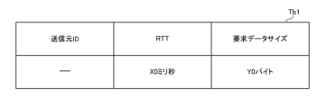
- FIG. 5 is a diagram showing an example of a correspondence table stored by an in-vehicle relay device according to the first embodiment of the present disclosure.
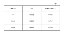
- the storage unit 54 stores a correspondence table Tb1 indicating the correspondence between the ID (Identifier) of the source functional unit (hereinafter also referred to as the "source ID") and the requested data size Dr.
- the correspondence table Tb1 is registered in the storage unit 54 by the manufacturer of the vehicle 1, for example, when the vehicle 1 is shipped.
- the "RTT" shown in FIG. 5 will be described later.
- the memory unit 54 further stores the data size Ds of each DoIP packet sent from the diagnostic device 201.
- the setting unit 61 determines that a communication connection between the diagnostic device 201 and its own vehicle-mounted relay device 101 has been established, it uses the correspondence table Tb1 and the data size Ds per DoIP packet stored in the memory unit 54 to calculate the number of requested packets Nr equivalent to the requested data size Dr of "Y0 bytes.”
- the setting unit 61 When the setting unit 61 calculates the number of requested packets Nr, in the setting process, it sets the TCP window size (hereinafter also simply referred to as "window size"), which is the data size equivalent to the maximum value M, to a value larger than the requested data size Dr equivalent to the calculated number of requested packets Nr, i.e., it limits the number of requested packets Nr to a value smaller than the maximum value M. Then, the setting unit 61 notifies the relay unit 52 of the set window size.
- window size which is the data size equivalent to the maximum value M
- the relay unit 52 When the relay unit 52 receives the notification from the setting unit 61, it creates an IP packet (hereinafter also referred to as "notification packet P0") that includes the notified window size and includes the IP address of its own vehicle-mounted relay device 101 and the IP address of the diagnostic device 201 as the source address and destination IP address, respectively. The relay unit 52 then transmits the created notification packet P0 to the diagnostic device 201.
- notification packet P0 an IP packet
- the relay unit 52 When a communication connection is established between the source function unit and its own vehicle-mounted relay device 101, the relay unit 52 receives a number of DoIP packets (hereinafter also referred to as "packets P10") corresponding to the maximum value M from the source function unit.
- packets P10 a number of DoIP packets
- the diagnostic device 201 when the diagnostic device 201 receives a notification packet P0 from the in-vehicle relay device 101, it transmits to the in-vehicle relay device 101 a number of packets P10 corresponding to the window size contained in the received notification packet P0.
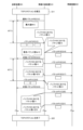
- FIG. 6 is a sequence diagram showing an example of the processing of a diagnostic device and an in-vehicle relay device in a communication system according to a first embodiment of the present disclosure.
- DoIP packets transmitted in communication system 501 are indicated by white rectangles.
- the in-vehicle relay device 101 transmits a notification packet P0 including a window size equivalent to the maximum value M to the diagnostic device 201.
- the diagnostic device 201 when the diagnostic device 201 receives notification packet P0 from the in-vehicle relay device 101, it transmits three packets P10 to the in-vehicle relay device 101 (step S13).
- the in-vehicle relay device 101 receives three packets P10 from the diagnostic device 201, it performs conversion processing on each of the received packets P10, and stores the three packets P10 after conversion processing in the buffer 55.
- the in-vehicle relay device 101 transmits to the in-vehicle device 202, a number of DoIP packets determined according to the throughput Th between the in-vehicle device 202 and the relay destination.
- the number of DoIP packets after conversion processing that the in-vehicle relay device 101 transmits to the in-vehicle device 202 is one.
- the number of packets P10 stored in the buffer 55 of the in-vehicle relay device 101 becomes two (step S14). Note that steps S15 and onward shown in FIG. 6 will be described later.
- the setting unit 61 determines the requested data size Dr based on the target value G of the throughput Th between its own vehicle-mounted relay device 101 and the vehicle-mounted equipment 202 to which the received packet P10 is to be relayed.
- the setting unit 61 performs a calculation process to calculate the number of requested packets Nr based on the target value G of the throughput Th and the round-trip time from when the relay unit 52 transmits the response packet P2 until it receives a DoIP packet (hereinafter also referred to as "packet P11") in response to the response packet P2.
- packet P11 a DoIP packet
- the round-trip time is also referred to as "RTT" (Round Trip Time).
- the relay unit 52 transmits a notification packet P0 to the diagnostic device 201, it outputs a transmission notification R0 indicating that the notification packet P0 has been transmitted to the measurement unit 62.
- the measurement unit 62 measures the RTT. For example, when the measurement unit 62 receives a transmission notification R0 from the relay unit 52, it starts a timer (not shown).
- the relay unit 52 When the relay unit 52 receives packet P10 in response to notification packet P0 from the diagnostic device 201, it outputs a reception notification R1 indicating that packet P10 has been received to the measurement unit 62.
- the measurement unit 62 When the measurement unit 62 receives the reception notification R1 from the relay unit 52, it stops the timer. The measurement unit 62 then measures the time from when the timer starts to when it stops as the RTT. After measuring the RTT, the measurement unit 62 reads out the correspondence table Tb1 in the memory unit 54.
- the correspondence table Tb1 shown in FIG. 5 further shows the correspondence between the sender ID and the RTT.
- the RTT "X0 milliseconds" is registered as the initial value.
- the measurement unit 62 checks whether the measured RTT matches the RTT indicated in the correspondence table Tb1 by referring to the correspondence table Tb1.
- the measurement unit 62 If the measured RTT matches the initial value of the RTT shown in the correspondence table Tb1, the measurement unit 62 outputs to the setting unit 61 measurement result information K1 indicating that the measured RTT matches the initial value and indicating the measured RTT.
- the measurement unit 62 outputs to the setting unit 61 measurement result information K2 indicating that the measured RTT differs from the initial value and indicating the measured RTT.
- the memory unit 54 further stores a target value G of the throughput Th.
- the target value G is registered in the memory unit 54 by the manufacturer of the vehicle 1, for example, when the vehicle 1 is shipped.
- the setting unit 61 calculates the requested data size Dr by multiplying the RTT indicated by the measurement result information K1 or K2 received from the measurement unit 62 by the target value G of the throughput Th stored in the memory unit 54.
- the setting unit 61 calculates the number of requested packets Nr using the calculated requested data size Dr and the data size Ds per DoIP packet stored in the memory unit 54, and outputs the calculated number of requested packets Nr to the relay unit 52. Furthermore, when the setting unit 61 calculates the requested data size Dr using the measurement result information K2 from the measurement unit 62, it outputs table update information T1 including the RTT indicated by the measurement result information K2 and the calculated requested data size Dr to the update unit 63.
- the relay unit 52 When the relay unit 52 receives a packet P10 from the diagnostic device 201 after notifying the maximum value M, the relay unit 52 performs a response process of transmitting a response packet P2 in response to the received packet P10 to the diagnostic device 201. For example, in the response process, the relay unit 52 notifies the diagnostic device 201 of control information for controlling the requested data size Dr determined by the setting unit 61.
- the relay unit 52 notifies the diagnostic device 201 of the acknowledgement response number (hereinafter also referred to as the "ACK number") contained in the response packet P2 as control information.
- ACK number the acknowledgement response number
- the relay unit 52 notifies the diagnostic device 201 of the number of request packets Nr calculated by the setting unit 61 by adjusting the ACK number included in the response packet P2.
- the relay unit 52 when the relay unit 52 receives the calculation result from the setting unit 61, it creates a response packet P2 that includes an ACK number obtained by adding the number of requested packets Nr indicated by the calculation result to the sequence number included in the packet P10 received from the diagnostic device 201. The relay unit 52 then transmits the created response packet P2 to the diagnostic device 201.
- the diagnostic device 201 When the diagnostic device 201 receives the response packet P2 from the in-vehicle relay device 101, it transmits to the in-vehicle relay device 101 packets P11 whose number is calculated by subtracting the sequence number contained in packet P10 from the ACK number contained in the received response packet P2.
- the vehicle-mounted relay device 101 transmits a response packet P2 to the diagnostic device 201.
- the vehicle-mounted relay device 101 measures the RTT1, which is the round trip time between the vehicle-mounted relay device 101 and the diagnostic device 201.
- the vehicle-mounted relay device 101 then multiplies the measured RTT1 by the target value G of the throughput Th to calculate the requested data size Dr and the number of requested packets Nr.
- the number of requested packets Nr is two.
- the vehicle-mounted relay device 101 transmits a response packet P2 including an ACK number adjusted so that the number of requested packets Nr is two to the diagnostic device 201 (step S15).
- the in-vehicle relay device 101 transmits one packet P10 after the conversion process to the in-vehicle device 202 as the relay destination.
- the number of packets P10 stored in the buffer 55 of the in-vehicle relay device 101 becomes one (step S16).
- the in-vehicle relay device 101 transmits one packet P10 after the conversion process to the in-vehicle device 202 as the relay destination.
- the number of packets P10 stored in the buffer 55 of the in-vehicle relay device 101 becomes zero (step S17).
- the in-vehicle repeater 101 receives two packets P11 from the diagnostic device 201 after RTT1 has elapsed since sending the response packet P2.
- the in-vehicle repeater 101 then performs a conversion process on each of the received packets P11, and stores the two packets P11 after the conversion process in the buffer 55 (step S18).
- the in-vehicle relay device 101 transmits a response packet P2 to the diagnostic device 201, the response packet P2 including a sequence number adjusted so that the number of requested packets Nr is two (step S19).
- the in-vehicle relay device 101 transmits the converted packet P11 to the in-vehicle device 202 as the relay destination.
- the number of packets P11 stored in the buffer 55 of the in-vehicle relay device 101 becomes one (step S20).
- the in-vehicle relay device 101 transmits the converted packet P11 to the in-vehicle device 202 as the relay destination.
- the number of packets P11 stored in the buffer 55 of the in-vehicle relay device 101 becomes zero (step S21).
- step S22 the diagnostic device 201 and the in-vehicle relay device 101 terminate the TCP connection.
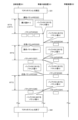
- FIG. 7 is a sequence diagram showing another example of the processing of the diagnostic device and the vehicle-mounted relay device in the communication system according to the first embodiment of the present disclosure.
- DoIP packets transmitted in the communication system 501 are indicated by white rectangles.
- step S31 to step S34 are similar to the processes from step S11 to step S14 shown in FIG. 6.
- the vehicle-mounted relay device 101 transmits a response packet P2 to the diagnostic device 201.
- the vehicle-mounted relay device 101 measures RTT2, which is the round-trip time between the vehicle-mounted relay device 101 and the diagnostic device 201, and calculates the requested data size Dr.
- RTT2 is a value smaller than RTT1 shown in FIG. 6.
- the in-vehicle relay device 101 transmits one packet P10 after the conversion process to the in-vehicle device 202 as the relay destination.
- the number of packets P10 stored in the buffer 55 of the in-vehicle relay device 101 becomes one (step S36).
- the in-vehicle repeater 101 receives one packet P11 from the diagnostic device 201 after RTT2 has elapsed since sending the response packet P2.
- the in-vehicle repeater 101 then performs a conversion process on the received packet P11, and stores the one packet P11 after the conversion process in the buffer 55.
- one packet P10 and one packet P11 are stored in the buffer 55.
- the number of DoIP packets stored in the buffer 55 becomes two (step S37).
- the in-vehicle relay device 101 transmits one of the converted packets P10 and P11 to the in-vehicle device 202 as the relay destination.
- the in-vehicle relay device 101 transmits one converted packet P10 to the in-vehicle device 202 as the relay destination.
- the number of DoIP packets stored in the buffer 55 becomes one, packet P11 (step S38).
- the in-vehicle relay device 101 transmits a response packet P2 to the diagnostic device 201, the response packet P2 including an ACK number adjusted so that the number of requested packets Nr is 1 (step S39).
- the in-vehicle repeater 101 receives one packet P11 from the diagnostic device 201 after RTT2 has elapsed since sending the response packet P2.
- the in-vehicle repeater 101 then performs a conversion process on the received packet P11, and stores the one packet P11 after the conversion process in the buffer 55. As a result, the number of packets P11 stored in the buffer 55 becomes two (step S40).
- the in-vehicle relay device 101 transmits one packet P11 after the conversion process to the in-vehicle device 202 as the relay destination.
- the number of packets P11 stored in the buffer 55 of the in-vehicle relay device 101 becomes one (step S41).
- step S42 the diagnostic device 201 and the in-vehicle relay device 101 terminate the TCP connection.
- Table update process For example, when the update unit 63 receives table update information T1 from the setting unit 61, the update unit 63 performs a table update process to update the correspondence table Tb1.
- the update unit 63 when the update unit 63 receives table update information T1 from the setting unit 61, it outputs ID request information indicating a request to transmit the ID of the diagnostic device 201 to the relay unit 52.
- the ARP table in the memory unit 54 further indicates the correspondence between the source ID and the destination IP address.
- the relay unit 52 When the relay unit 52 receives ID request information from the update unit 63, it refers to the ARP table in the storage unit 54 to identify the source ID that corresponds to the destination IP address included in the DoIP packet stored in the buffer 55. The relay unit 52 then notifies the update unit 63 of the identified source ID.
- the update unit 63 When the update unit 63 receives a notification from the relay unit 52, it reads out the correspondence table Tb1 in the storage unit 54. The update unit 63 then registers in the correspondence table Tb1 the sender ID notified by the relay unit 52 and the RTT and requested data size Dr included in the table update information T1 received from the setting unit 61 in association with each other.
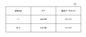
- FIG. 8 shows an example of an updated correspondence table stored by an in-vehicle relay device according to the first embodiment of the present disclosure.
- the sender ID "ID-A”, the RTT "X1 milliseconds”, and the requested data size "Y1 bytes" are registered in correspondence with each other.
- the setting unit 61 determines the requested data size Dr based on the updated correspondence table Tb1.
- the relay unit 52 when the relay unit 52 receives packet P11 after sending response packet P2, it refers to the ARP table in the storage unit 54 to identify the source ID corresponding to the destination IP address included in the received packet P11, and notifies the setting unit 61 of the identified source ID.
- the setting unit 61 When the setting unit 61 receives a notification from the relay unit 52, it reads out the correspondence table Tb1 in the storage unit 54. The setting unit 61 then refers to the correspondence table Tb1 to identify the requested data size Dr that corresponds to the sender ID notified by the relay unit 52.
- the setting unit 61 uses the data size Ds of each DoIP packet stored in the memory unit 54 to calculate the number of requested packets Nr that corresponds to the identified requested data size Dr, and notifies the relay unit 52 of the calculated number of requested packets Nr.
- the setting unit 61 may store the calculation result in the storage unit 54. In this case, upon receiving a notification from the relay unit 52, the setting unit 61 notifies the relay unit 52 of the number of requested packets Nr stored in the storage unit 54.
- the relay unit 52 When the relay unit 52 receives a notification from the setting unit 61, it notifies the diagnostic device 201 of the notified number of request packets Nr in the response process.
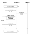
- FIG. 9 is a flowchart defining an operation procedure when the vehicle-mounted relay device according to the first embodiment of the present disclosure performs the setting process and the response process.
- the in-vehicle relay device 101 sets a maximum value M to be notified to the diagnostic device 201. For example, as described above, the in-vehicle relay device 101 sets a window size equivalent to the maximum value M of the number of DoIP packets that the diagnostic device 201 can send to itself per unit time (step S102).
- the in-vehicle relay device 101 transmits a notification packet P0 including the set window size to the diagnostic device 201 (step S103).
- the vehicle-mounted relay device 101 waits for the arrival of packet P10 from the diagnostic device 201 in response to the notification packet P0 (NO in step S104), and when it receives packet P10 (YES in step S104), it measures the RTT (step S105).
- the vehicle-mounted relay device 101 calculates the requested data size Dr. For example, as described above, the vehicle-mounted relay device 101 calculates the requested data size Dr by multiplying the measured RTT by the target value G of the throughput Th stored in the memory unit 54 (step S106).
- the vehicle-mounted relay device 101 performs a table update process to update the correspondence table Tb1. For example, as described above, the vehicle-mounted relay device 101 registers the sender ID of the diagnostic device 201, the measured RTT, and the calculated requested data size Dr in the correspondence table Tb1 in association with each other (step S108).
- the vehicle-mounted repeater 101 completes the table update process (step S108), or if the measured RTT is the same as the initial RTT value indicated in the correspondence table Tb1 (NO in step S107), it transmits a response packet P2 based on the requested data size Dr to the diagnostic device 201.
- the vehicle-mounted repeater 101 notifies the diagnostic device 201 of the number of requested packets Nr equivalent to the calculated requested data size Dr by adjusting the ACK number included in the response packet P2 (step S109).
- the vehicle-mounted relay device 101 waits for the arrival of packet P11 in response to response packet P2 (NO in step S110).
- the in-vehicle relay device 101 receives packet P11 in response to response packet P2 from the diagnostic device 201 (YES in step S110), it transmits a response packet P2 based on the requested data size Dr to the diagnostic device 201 (step S109).
- step S111 the vehicle relay device 101 waits for a new TCP connection to be established (NO in step S101).
- the vehicle relay device 101 may be configured to perform the following process for determining the number of requested packets Nr.
- FIG. 10 is a diagram showing the configuration of a modified communication system according to the first embodiment of the present disclosure.
- communication system 501A includes in-vehicle system 301 and multiple diagnostic devices 201, that is, diagnostic devices 201A and 201B.
- the sender IDs of diagnostic devices 201A and 201B are assumed to be "ID-A1" and "ID-A2", respectively.
- the sender ID is a unique ID for each diagnostic device 201.
- the diagnostic devices 201A and 201B are connected to the communication ports 51C and 51D of the vehicle-mounted relay device 101 via the LAN cables 12A and 12B, respectively.
- the communication system 501A is not limited to a configuration including two diagnostic devices 201, and may be a configuration including three or more diagnostic devices 201.
- FIG. 11 is a diagram showing the configuration of a modified example of an in-vehicle relay device according to the first embodiment of the present disclosure.
- the in-vehicle relay device 101A in comparison with the in-vehicle relay device 101 shown in FIG. 3, includes a relay unit 52A instead of the relay unit 52.
- the processing unit 53 in the in-vehicle relay device 101A includes an update unit 63A instead of the update unit 63.
- the update unit 63A is an example of a round trip time determination unit.
- the relay unit 52A communicates with multiple diagnostic devices 201. More specifically, for example, the relay unit 52A transmits and receives packets to and from each diagnostic device 201 in accordance with TCP/IP.
- the relay unit 52A When the relay unit 52A receives packet P10 in response to notification packet P0 from each diagnostic device 201, it notifies the measurement unit 62 of the source ID of the diagnostic device 201.
- the measurement unit 62 starts the timer when it receives the above-mentioned transmission notification R0 from the relay unit 52A, and then stops the timer when it receives the reception notification R21 from the relay unit 52A.
- the measurement unit 62 measures the RTT and checks whether the measured RTT matches the initial value of the RTT indicated in the correspondence table Tb1 in the memory unit 54.
- the RTT between the in-vehicle relay device 101 and the diagnostic device 201A, and the RTT between the in-vehicle relay device 101 and the diagnostic device 201B are assumed to be different from the initial RTT value "X0 milliseconds" shown in the correspondence table Tb1 shown in FIG. 5.
- the measurement unit 62 If the measured RTT differs from the initial value of the RTT indicated in the correspondence table Tb1, the measurement unit 62 outputs to the setting unit 61 measurement result information K21 indicating that the measured RTT differs from the initial value, the measured RTT, and the source ID notified by the relay unit 52A.
- the setting unit 61 calculates the number of requested packets Nr using the measurement result information K21 from the measurement unit 62, it outputs table update information T2 to the update unit 63A, the table update information T2 including the source ID and RTT indicated by the measurement result information K21, and the requested data size Dr corresponding to the calculated number of requested packets Nr.
- the update unit 63A determines the RTT depending on the diagnostic device 201. More specifically, when the update unit 63A receives table update information T2 from the setting unit 61, it reads out the correspondence table Tb1 in the storage unit 54. Then, the update unit 63A registers the sender ID, RTT, and requested data size Dr included in the table update information T2 in correspondence table Tb1.
- FIG. 12 is a diagram showing an example of an updated correspondence table stored in a modified example of an in-vehicle relay device according to the first embodiment of the present disclosure.
- the sender ID "ID-A1”, the RTT “X1 milliseconds”, and the requested data size Dr “Y1 bytes” are registered in association with each other.
- the sender ID "ID-A2”, the RTT “X2 milliseconds”, and the requested data size Dr “Y2 bytes” are registered in association with each other.
- the update unit 63A When the update unit 63A completes the table update process, it outputs an update completion notification to the setting unit 61, indicating that the table update process has been completed.
- the setting unit 61 calculates the number of requested packets Nr based on the RTT determined by the update unit 63A.
- the setting unit 61 when the setting unit 61 receives an update completion notification from the update unit 63A and a source ID from the relay unit 52A, it reads the correspondence table Tb1 in the storage unit 54. The setting unit 61 then refers to the correspondence table Tb1 to identify the requested data size Dr that corresponds to the source ID received from the relay unit 52A.
- the setting unit 61 uses the data size Ds of each DoIP packet stored in the memory unit 54 to calculate the number of requested packets Nr that corresponds to the specified requested data size Dr, and outputs the calculated number of requested packets Nr to the relay unit 52A.
- the vehicle-mounted relay device 101 is configured to determine the requested data size Dr based on the target value G of the throughput Th between the vehicle-mounted device 202 to which the DoIP packets are to be relayed, and the RTT between the vehicle-mounted relay device 101 and the diagnostic device 201, but this is not limited to the above.
- the vehicle-mounted relay device 101 may be configured to determine the requested data size Dr based on either the target value G of the throughput Th or the RTT.
- the vehicle-mounted relay device 101 is configured to notify the diagnostic device 201 of the number of request packets Nr equivalent to the requested data size Dr in the response process, but this is not limited to this.
- the vehicle-mounted relay device 101 may be configured to notify the diagnostic device 201 of the requested data size Dr in the response process.
- the diagnostic device 201 stores the data size Ds of one DoIP packet. Then, the diagnostic device 201 uses the data size Ds to calculate the number of request packets Nr equivalent to the requested data size Dr notified by the vehicle-mounted relay device 101.
- the vehicle relay device 101 is configured to measure the RTT between the vehicle relay device 101 and the diagnostic device 201 and calculate the requested data size Dr based on the measured RTT, but this is not limited to the above.
- the RTT may be registered in advance in the storage unit 54 by the manufacturer of the vehicle 1.
- the vehicle relay device 101 does not measure the RTT, but calculates the requested data size Dr based on the RTT stored in the storage unit 54.
- the storage unit of the diagnostic device 201 may be configured to store the RTT.
- the vehicle relay device 101 does not measure the RTT, and for example, when a communication connection between the vehicle relay device 101 and the diagnostic device 201 is established, the vehicle relay device 101 requests the diagnostic device 201 to transmit information indicating the RTT. Then, the vehicle relay device 101 calculates the requested data size Dr based on the information received from the diagnostic device 201.
- the vehicle-mounted relay device 101 is configured to notify the diagnosis device 201 of the confirmation response number included in the response packet P2 as control information, but this is not limited to this.
- the vehicle-mounted relay device 101 may also be configured to include the number of request packets Nr in the response packet P2 and transmit it to the diagnosis device 201.
- the in-vehicle relay device 101 is configured to establish a TCP connection with one diagnostic device 201 and notify the diagnostic device 201 of the calculated number of requested packets Nr, but this is not limited to the above.
- the in-vehicle relay device 101 may be configured to notify each diagnostic device 201 of a common number of requested packets Nr.
- the storage unit 54 in the vehicle-mounted relay device 101 is configured to store the target value G of the throughput Th registered by the manufacturer of the vehicle 1, but this is not limited to this.
- the vehicle-mounted relay device 101 may be configured to update the target value G according to the state of its own resources, for example, the usage rate of at least one of the buffer 55 and the CPU (Central Processing Unit).
- the in-vehicle relay device 101 performs setting processing and response processing in a configuration in which the IP packet from the diagnostic device 201 is relayed to the in-vehicle device 202.
- the in-vehicle relay device 102 performs setting processing and response processing in a configuration in which the IP packet from the in-vehicle device 202 is relayed to the diagnostic device 201.
- Contents other than those described below are the same as those of the in-vehicle relay device 101 according to the first embodiment.
- FIG. 13 is a diagram showing the configuration of an in-vehicle relay device according to a second embodiment of the present disclosure.
- the in-vehicle relay device 102 includes a relay unit 252 instead of the relay unit 52, and a processing unit 253 instead of the processing unit 53.
- the processing unit 253 includes a setting unit 261 instead of the setting unit 61.
- One or both of the relay unit 252 and the processing unit 253 are realized, for example, by a processing circuit including one or more processors.
- the storage unit 54 is, for example, a non-volatile memory included in the processing circuit.
- the relay unit 252 communicates with multiple in-vehicle devices 202. Specifically, for example, the relay unit 252 transmits and receives IP packets to and from each in-vehicle device 202 in accordance with TCP/IP, similar to the relay unit 52 shown in FIG. 3.
- the vehicle-mounted device 202 creates an IP packet (hereinafter also referred to as "packet P31") that includes diagnostic information used in fault diagnosis and includes its own IP address and the IP address of the diagnostic device 201 as the source IP address and destination IP address, respectively.
- packet P31 an IP packet that includes diagnostic information used in fault diagnosis and includes its own IP address and the IP address of the diagnostic device 201 as the source IP address and destination IP address, respectively.
- the vehicle-mounted device 202 then transmits the created packet P31 to the diagnostic device 201 via the vehicle-mounted relay device 102.
- the relay unit 252 when the relay unit 252 receives packet P31 from the in-vehicle device 202, it stores the received packet P31 in the buffer 55 and transmits packet P31 to the diagnostic device 201.
- the storage unit 54 further stores an address table Tb20 that indicates the correspondence between destination IP addresses and communication ports.
- the relay unit 252 When the relay unit 252 receives a packet P31 from the in-vehicle device 202, it identifies the communication port 51 that corresponds to the destination IP address included in the packet P31 by referring to the address table Tb20 in the storage unit 54. Then, the relay unit 252 transmits the packet P31 received from the in-vehicle device 202 to the diagnostic device 201 from the identified communication port 51.
- the diagnostic device 201 When the diagnostic device 201 receives the packet P31 from the in-vehicle relay device 102, the diagnostic device 201 performs a predetermined process based on the received packet P31. For example, the diagnostic device 201 performs a fault diagnosis of the in-vehicle device 202 based on the diagnostic information contained in the packet P31 received from the in-vehicle relay device 102.
- the setting unit 261 performs a setting process for setting the maximum value M when a communication connection between the vehicle-mounted device 202 and the vehicle-mounted relay device 102 is established.
- the setting unit 261 monitors IP packets received by the relay unit 252, and when it determines that a communication connection between the in-vehicle device 202 and its own in-vehicle relay device 102 has been established, it outputs an ID request notification to the relay unit 252, requesting the transmission of the sender ID.
- the relay unit 252 When the relay unit 252 receives an ID request notification from the setting unit 261, it notifies the setting unit 261 of the sender ID included in the IP packet received by its own in-vehicle relay device 102 during the process of establishing a TCP connection with the in-vehicle device 202.
- FIG. 14 is a diagram showing an example of a correspondence table stored by an in-vehicle relay device according to the second embodiment of the present disclosure.
- the storage unit 54 stores, for example, a correspondence table Tb2 indicating the correspondence between the sender ID and the requested data size.
- the requested data size corresponding to sender ID "ID-B1" is “Z1 bytes.”
- the requested data size corresponding to sender ID "ID-B2" is "Z2 bytes.”
- the setting unit 261 when the setting unit 261 receives a notification from the relay unit 252, it refers to the correspondence table Tb2 in the storage unit 54 to identify the requested data size Dr that corresponds to the sender ID notified by the relay unit 252.
- the setting unit 261 calculates the number of requested packets Nr that corresponds to the requested data size Dr based on the identified requested data size Dr and the data size Ds per packet P31 stored in the memory unit 54.
- the setting unit 261 calculates the number of requested packets Nr, in the setting process, it sets the maximum value M to a value smaller than the calculated number of requested packets Nr. Then, the setting unit 261 notifies the relay unit 252 of the window size equivalent to the maximum value M.
- the relay unit 252 When the relay unit 252 receives the notification from the setting unit 261, it creates an IP packet (hereinafter also referred to as "notification packet P30") that includes the notified window size and that includes the IP address of its own in-vehicle relay device 102 and the IP address of the diagnostic device 201 as the source address and destination IP address, respectively. Then, the relay unit 252 transmits the created notification packet P30 to the in-vehicle device 202.
- notification packet P30 an IP packet that includes the notified window size and that includes the IP address of its own in-vehicle relay device 102 and the IP address of the diagnostic device 201 as the source address and destination IP address, respectively. Then, the relay unit 252 transmits the created notification packet P30 to the in-vehicle device 202.
- the in-vehicle device 202 When the in-vehicle device 202 receives a notification packet P30 from the in-vehicle relay device 102, it transmits to the in-vehicle relay device 102 a number of packets P31 equivalent to the window size contained in the received notification packet P30.
- the setting unit 261 determines the requested data size Dr depending on the type of the in-vehicle device 202.
- the storage unit 54 further stores an address table Tb20 that indicates the correspondence between destination IP addresses and source IDs.
- the relay unit 252 When the relay unit 252 receives packet P31 from the in-vehicle device 202 after notifying the window size equivalent to the maximum value M, the relay unit 252 identifies the source ID corresponding to the destination IP address included in packet P31 by referring to the address table Tb20 in the memory unit 54, and notifies the setting unit 261 of the identified source ID.
- the setting unit 261 When the setting unit 261 receives a notification from the relay unit 252, it refers to the correspondence table Tb2 in the memory unit 54 to identify the requested data size Dr that corresponds to the sender ID notified by the relay unit 252.
- the setting unit 261 calculates the number of requested packets Nr equivalent to the requested data size Dr based on the identified requested data size Dr and the data size Ds per packet P31 stored in the memory unit 54. The setting unit 261 then notifies the relay unit 252 of the calculated number of requested packets Nr.
- the setting unit 261 may store the calculated number of requested packets Nr in the storage unit 54 in the above setting process. In this case, upon receiving a notification from the relay unit 252, the setting unit 261 notifies the relay unit 252 of the number of requested packets Nr stored in the storage unit 54.
- the relay unit 252 notifies the source in-vehicle device 202 of the number of requested packets Nr determined by the setting unit 261.
- the relay unit 252 when the relay unit 252 receives a notification from the setting unit 261, it creates a response packet P2 that includes a sequence number obtained by adding the number of request packets Nr notified by the setting unit 261 to the sequence number included in the immediately preceding packet P31 from the source in-vehicle device 202. The relay unit 252 then transmits the created response packet P2 to the source in-vehicle device 202.
- [Operation flow] 15 is a flowchart that defines an operation procedure when the in-vehicle relay device according to the second embodiment of the present disclosure performs a setting process and a response process.
- the operation procedure when the in-vehicle relay device 102 performs the setting process and the response process in the case where the in-vehicle relay device 102 relays the packet P31 from the in-vehicle device 202A to the diagnostic device 201 will be described.
- the in-vehicle repeater 102 sets a maximum value M to be notified to the in-vehicle device 202 that is the source of the packet P31. For example, as described above, the in-vehicle repeater 101 sets a window size equivalent to the maximum value M of the number of packets P31 that the in-vehicle device 202 can send to itself per unit time (step S202).
- the in-vehicle relay device 102 transmits a notification packet P30 including the set window size to the in-vehicle device 202A (step S203).
- the in-vehicle relay device 102 waits for the arrival of packet P31 from the in-vehicle device 202A in response to the notification packet P30 (NO in step S204), and upon receiving packet P31 (YES in step S204), determines the requested data size Dr. For example, as described above, the in-vehicle relay device 102 identifies the requested data size Dr corresponding to the sender ID of the in-vehicle device 202A by referring to the correspondence table Tb2 in the memory unit 54 (step S205).
- the in-vehicle relay device 102 transmits a response packet P2 based on the determined number of request packets Nr to the in-vehicle device 202A. For example, as described above, the in-vehicle relay device 102 notifies the in-vehicle device 202A of the number of request packets Nr equivalent to the calculated request data size Dr by adjusting the ACK number included in the response packet P2 (step S206).
- the vehicle-mounted relay device 102 waits for the arrival of packet P31 in response to response packet P2 (NO in step S207).
- the in-vehicle relay device 102 receives packet P31 in response to response packet P2 from the in-vehicle device 202A (YES in step S207), it transmits a response packet P2 based on the requested data size Dr to the in-vehicle device 202A (step S206).
- the vehicle-mounted relay device 102 waits for a new TCP connection to be established (NO in step S201).
- the in-vehicle relay device 102 is configured to determine the requested data size Dr according to the in-vehicle device 202 and notify the in-vehicle device 202 of the requested packet number Nr corresponding to the determined requested data size Dr, but this is not limited to the above.
- the in-vehicle relay device 102 may also be configured to notify each in-vehicle device 202 of a common requested packet number Nr.
- the in-vehicle relay device 102 is configured to determine the requested data size Dr based on the correspondence table Tb2, but this is not limited to the above.
- the in-vehicle relay device 102 may be configured to measure the RTT between the in-vehicle device 202 and determine the requested data size Dr based on the measured RTT and the target value of the throughput between the diagnostic device to which the packet P31 is relayed, similar to the in-vehicle relay device 101 according to the first embodiment.
- Each process (each function) in the above-mentioned embodiments is realized by a processing circuit including one or more processors.
- the processing circuit may be composed of an integrated circuit or the like that combines one or more memories, various analog circuits, and various digital circuits in addition to the one or more processors.
- the one or more memories store programs (instructions) that cause the one or more processors to execute each of the above processes.
- the one or more processors may execute each of the above processes according to the programs read from the one or more memories, or may execute each of the above processes according to a logic circuit designed in advance to execute each of the above processes.
- the processor may be various processors suitable for computer control, such as a CPU, a GPU (Graphics Processing Unit), a DSP (Digital Signal Processor), an FPGA (Field Programmable Gate Array), and an ASIC (Application Specific Integrated Circuit).
- the physically separated processors may cooperate with each other to execute the above processes.
- the processors mounted on each of the physically separated computers may cooperate with each other via a network such as a LAN (Local Area Network), a WAN (Wide Area Network), and the Internet to execute the above processes.
- the above program may be installed into the memory from an external server device or the like via the network, or may be distributed in a state stored on a recording medium such as a CD-ROM (Compact Disc Read Only Memory), DVD-ROM (Digital Versatile Disc Read Only Memory), or semiconductor memory, and installed into the memory from the recording medium.
- a recording medium such as a CD-ROM (Compact Disc Read Only Memory), DVD-ROM (Digital Versatile Disc Read Only Memory), or semiconductor memory, and installed into the memory from the recording medium.
- An in-vehicle relay device that relays packets transmitted and received between functional units, A processing circuit is provided, The processing circuitry includes: a window size is set as a maximum value of a data size of the packet that a source functional unit, which is a source of the packet, can transmit to the vehicle-mounted relay device, and is to be notified to the source functional unit when a communication connection between the source functional unit and the vehicle-mounted relay device is established; notifying the source functional unit of the set window size; when receiving the packet from the source functional unit after notifying the source functional unit of the window size, a response process is performed in which a response packet for the received packet includes control information for controlling a requested data size, which is a data size of the packet that is requested to be transmitted by the source functional unit, and the response packet is transmitted to the source functional unit; The vehicle-mounted relay device sets the window size to a value larger than the requested data size.
Landscapes
- Engineering & Computer Science (AREA)
- Computer Networks & Wireless Communication (AREA)
- Signal Processing (AREA)
- Mechanical Engineering (AREA)
- Small-Scale Networks (AREA)
Abstract
車載中継装置は、パケットの送信元機能部が前記車載中継装置へ送信可能な前記パケットのデータサイズの最大値であって、前記送信元機能部と前記車載中継装置との通信接続が確立した場合に前記送信元機能部へ通知する前記最大値であるウィンドウサイズを設定する設定部と、前記設定部によって設定された前記ウィンドウサイズを前記送信元機能部へ通知する通信部とを備え、前記通信部は、前記ウィンドウサイズの通知後に前記送信元機能部から前記パケットを受信した場合、受信した前記パケットに対する応答パケットに、前記送信元機能部に送信を要求する前記パケットの要求データサイズを制御するための制御情報を含めて前記送信元機能部へ送信する応答処理を行い、前記設定部は、前記ウィンドウサイズを前記要求データサイズより大きい値に設定する。
Description
本開示は、車載中継装置、中継方法および中継プログラムに関する。
この出願は、2023年6月16日に出願された日本出願特願2023-99499号を基礎とする優先権を主張し、その開示のすべてをここに取り込む。
この出願は、2023年6月16日に出願された日本出願特願2023-99499号を基礎とする優先権を主張し、その開示のすべてをここに取り込む。
特許文献1(特開2015-147446号公報)には、以下のような車両制御装置が開示されている。すなわち、車両制御装置は、車両に搭載されネットワークによって接続される複数の単位車両制御装置を有し、少なくとも1つの単位車両制御装置に車両を識別する車両識別コードを記憶した車両制御装置であって、前記単位車両制御装置の夫々は通信を介して外部の診断装置とメッセージのやり取りを行うノードを備えており、前記夫々のノードの一つを代表ノードとし、前記代表ノードが有する固別識別情報を車両識別用情報として他のノードに転送、記憶させ、前記診断装置から前記夫々のノードに対して送信される車両識別要求メッセージに対して前記各ノードは、前記車両識別コードと前記各ノード自身に記憶された前記車両識別用情報を含む車両識別応答メッセージ、或いは前記車両識別コードを含まず前記各ノード自身に記憶された前記車両識別用情報を含む車両識別応答メッセージのいずれかを返信することを特徴とする。
本開示の車載中継装置は、機能部間において送受信されるパケットを中継する車載中継装置であって、前記パケットの送信元の前記機能部である送信元機能部が前記車載中継装置へ送信可能な前記パケットのデータサイズの最大値であって、前記送信元機能部と前記車載中継装置との通信接続が確立した場合に前記送信元機能部へ通知する前記最大値であるウィンドウサイズを設定する設定部と、前記設定部によって設定された前記ウィンドウサイズを前記送信元機能部へ通知する通信部とを備え、前記通信部は、前記ウィンドウサイズの通知後に前記送信元機能部から前記パケットを受信した場合、受信した前記パケットに対する応答パケットに、前記送信元機能部に送信を要求する前記パケットのデータサイズである要求データサイズを制御するための制御情報を含めて前記送信元機能部へ送信する応答処理を行い、前記設定部は、前記ウィンドウサイズを前記要求データサイズより大きい値に設定する。
本開示の一態様は、このような特徴的な処理部を備える車載中継装置として実現され得るだけでなく、車載中継装置の一部または全部を実現する半導体集積回路として実現され得たり、車載中継装置を含むシステムとして実現され得る。
従来、機能部間において送受信されるパケットを中継する車載中継装置が開発されている。
[本開示が解決しようとする課題]
車載中継装置は、たとえば、パケットを中継先の機能部へ送信した後に、当該パケットの送信元の機能部に新たなパケットの送信を要求する場合がある。この場合、車載中継装置がパケットを中継先の機能部へ送信してから新たなパケットを送信元の機能部から受信するまでの空き時間が発生し、当該送信元の機能部と車載中継装置との間のスループットが低下または不安定となる可能性がある。車載ネットワークにおける限られたリソースの中で安定したスループットを実現することが可能な技術が望まれる。
車載中継装置は、たとえば、パケットを中継先の機能部へ送信した後に、当該パケットの送信元の機能部に新たなパケットの送信を要求する場合がある。この場合、車載中継装置がパケットを中継先の機能部へ送信してから新たなパケットを送信元の機能部から受信するまでの空き時間が発生し、当該送信元の機能部と車載中継装置との間のスループットが低下または不安定となる可能性がある。車載ネットワークにおける限られたリソースの中で安定したスループットを実現することが可能な技術が望まれる。
本開示は、上述の課題を解決するためになされたもので、その目的は、車載ネットワークのパケット伝送において安定したスループットを実現することが可能な車載中継装置、中継方法および中継プログラムを提供することである。
[本開示の効果]
本開示によれば、車載ネットワークのパケット伝送において安定したスループットを実現することができる。
本開示によれば、車載ネットワークのパケット伝送において安定したスループットを実現することができる。
[本開示の実施形態の説明]
最初に、本開示の実施の形態の内容を列記して説明する。
(1)本開示の実施の形態に係る車載中継装置は、機能部間において送受信されるパケットを中継する車載中継装置であって、前記パケットの送信元の前記機能部である送信元機能部が前記車載中継装置へ送信可能な前記パケットのデータサイズの最大値であって、前記送信元機能部と前記車載中継装置との通信接続が確立した場合に前記送信元機能部へ通知する前記最大値であるウィンドウサイズを設定する設定部と、前記設定部によって設定された前記ウィンドウサイズを前記送信元機能部へ通知する通信部とを備え、前記通信部は、前記ウィンドウサイズの通知後に前記送信元機能部から前記パケットを受信した場合、受信した前記パケットに対する応答パケットに、前記送信元機能部に送信を要求する前記パケットのデータサイズである要求データサイズを制御するための制御情報を含めて前記送信元機能部へ送信する応答処理を行い、前記設定部は、前記ウィンドウサイズを前記要求データサイズより大きい値に設定する。
最初に、本開示の実施の形態の内容を列記して説明する。
(1)本開示の実施の形態に係る車載中継装置は、機能部間において送受信されるパケットを中継する車載中継装置であって、前記パケットの送信元の前記機能部である送信元機能部が前記車載中継装置へ送信可能な前記パケットのデータサイズの最大値であって、前記送信元機能部と前記車載中継装置との通信接続が確立した場合に前記送信元機能部へ通知する前記最大値であるウィンドウサイズを設定する設定部と、前記設定部によって設定された前記ウィンドウサイズを前記送信元機能部へ通知する通信部とを備え、前記通信部は、前記ウィンドウサイズの通知後に前記送信元機能部から前記パケットを受信した場合、受信した前記パケットに対する応答パケットに、前記送信元機能部に送信を要求する前記パケットのデータサイズである要求データサイズを制御するための制御情報を含めて前記送信元機能部へ送信する応答処理を行い、前記設定部は、前記ウィンドウサイズを前記要求データサイズより大きい値に設定する。
このように、パケットの送信元の機能部との通信接続を確立した場合、当該機能部に対して、応答処理において通知する要求データサイズより大きいウィンドウサイズを通知する構成により、中継先の機能部へ送信するパケットの単位時間あたりの数より大きい数のパケットを受信することができるため、要求した新たなパケットが送信元の機能部から到着するまでの期間において、受信済のパケットを中継先の機能部へ送信することができる。したがって、パケット伝送において安定したスループットを実現することができる。
(2)上記(1)において、前記設定部は、前記通信部が前記ウィンドウサイズの通知後に前記送信元機能部から前記パケットを受信した場合、前記車載中継装置と受信された前記パケットの中継先の前記機能部との間のスループットの目標値に基づいて、前記要求データサイズを決定してもよく、前記通信部は、前記応答処理において、前記設定部によって決定された前記要求データサイズを制御するための前記制御情報を前記送信元機能部へ通知してもよい。
このような構成により、車載中継装置と中継先の機能部との間のスループットの目標値に応じて、送信元の機能部へ通知する要求データサイズを調整することができるため、当該スループットを安定させ、かつ目標値に近づけることができる。
(3)上記(1)または(2)において、前記設定部は、前記通信部が前記ウィンドウサイズの通知後に前記送信元機能部から前記パケットを受信した場合、前記通信部が前記応答パケットを送信してから前記応答パケットに対する前記パケットを受信するまでの往復時間に基づいて、前記要求データサイズを算出する算出処理を行ってもよく、前記通信部は、前記応答処理において、前記設定部によって算出された前記要求データサイズを制御するための前記制御情報を前記送信元機能部へ通知してもよい。
このような構成により、車載中継装置および送信元の機能部間におけるパケットの往復時間に応じて、送信元の機能部へ通知する要求データサイズを調整することができるため、当該往復時間の大小を考慮した要求データサイズを送信元の機能部へ通知することができる。
(4)上記(3)において、前記車載中継装置は、前記往復時間を計測する計測部を備えてもよく、前記設定部は、前記算出処理において、前記計測部によって計測された前記往復時間に基づいて、前記要求データサイズを算出してもよい。
このような構成により、往復時間の実測値に基づく要求データサイズを送信元の機能部へ通知することができるため、車載ネットワークの負荷状況に応じたより正確な要求データサイズを送信元の機能部へ通知することができる。
(5)上記(3)において、前記通信部は、複数の前記送信元機能部と通信を行ってもよく、前記車載中継装置は、さらに、前記送信元機能部の別に応じて前記往復時間を決定する往復時間決定部を備えてもよく、前記設定部は、前記算出処理において、前記往復時間決定部によって決定された前記往復時間に基づいて、前記要求データサイズを算出してもよい。
このような構成により、送信元の機能部ごとの往復時間に応じた適切な要求データサイズを通知することができるため、各送信元の機能部からのパケットを中継先の機能部へ送信する場合においてより安定したスループットを実現することができる。
(6)上記(1)または(2)において、前記通信部は、複数の前記送信元機能部と通信を行ってもよく、前記設定部は、前記通信部によって前記パケットが受信された場合、前記送信元機能部の別に応じて前記要求データサイズを決定してもよく、前記通信部は、前記応答処理において、前記設定部によって決定された前記要求データサイズを制御するための前記制御情報を前記送信元機能部へ通知してもよい。
このような構成により、各送信元の機能部に対して適切な要求データサイズを通知することができるため、各送信元の機能部からのパケットを中継先の機能部へ送信する場合においてより安定したスループットを実現することができる。
(7)上記(1)から(6)のいずれかにおいて、前記通信部は、前記応答処理において、前記応答パケットに含まれる確認応答番号を前記制御情報として前記送信元機能部へ通知する。
このような構成により、既存の確認応答番号を利用した簡易な処理で要求データサイズを送信元の機能部へ通知することができる。
(8)上記(1)から(7)のいずれかにおいて、前記送信元機能部は、前記車載中継装置を含む車載ネットワークの外部に設けられ、LANケーブルを介して前記車載中継装置と接続されてもよく、前記通信部は、前記車載ネットワークに設けられた前記機能部へ前記パケットを中継してもよい。
このような構成により、たとえば車両の故障診断を行う場合において、診断用の装置が接続される車載ネットワークのパケット伝送において安定したスループットを実現することができる。
(9)本開示の実施の形態に係る中継方法は、機能部間において送受信されるパケットを中継する車載中継装置における中継方法であって、前記パケットの送信元の前記機能部である送信元機能部が前記車載中継装置へ送信可能な前記パケットの単位時間あたりの数の最大値に相当するデータサイズであって、前記送信元機能部と前記車載中継装置との通信接続が確立した場合に前記送信元機能部へ通知する前記データサイズであるウィンドウサイズを設定するステップと、設定した前記ウィンドウサイズを前記送信元機能部へ通知するステップと、前記ウィンドウサイズの通知後に前記送信元機能部から前記パケットを受信した場合、受信した前記パケットに対する応答パケットに、前記送信元機能部に送信を要求する前記パケットの単位時間あたりの数に相当するデータサイズである要求データサイズを制御するための制御情報を含めて前記送信元機能部へ送信する応答処理を行うステップとを含み、前記ウィンドウサイズを設定するステップにおいて、前記ウィンドウサイズを前記要求データサイズより大きい値に設定する。
このように、パケットの送信元の機能部との通信接続を確立した場合、当該機能部に対して、応答処理において通知する要求データサイズより大きいウィンドウサイズを通知する構成により、中継先の機能部へ送信するパケットの単位時間あたりの数より大きい数のパケットを受信することができるため、要求した新たなパケットが送信元の機能部から到着するまでの期間において、受信済のパケットを中継先の機能部へ送信することができる。したがって、パケット伝送において安定したスループットを実現することができる。
(10)本開示の実施の形態に係る中継プログラムは、機能部間において送受信されるパケットを中継する車載中継装置において用いられる中継プログラムであって、コンピュータを、前記パケットの送信元の前記機能部である送信元機能部が前記車載中継装置へ送信可能な前記パケットのデータサイズの最大値であって、前記送信元機能部と前記車載中継装置との通信接続が確立した場合に前記送信元機能部へ通知する前記最大値であるウィンドウサイズを設定する設定部と、前記設定部によって設定された前記ウィンドウサイズを前記送信元機能部へ通知する通信部、として機能させるためのプログラムであり、前記通信部は、前記ウィンドウサイズの通知後に前記送信元機能部から前記パケットを受信した場合、受信した前記パケットに対する応答パケットに、前記送信元機能部に送信を要求する前記パケットのデータサイズである要求データサイズを制御するための制御情報を含めて前記送信元機能部へ送信する応答処理を行い、前記設定部は、前記ウィンドウサイズを前記要求データサイズより大きい値に設定する。
このように、パケットの送信元の機能部との通信接続を確立した場合、当該機能部に対して、応答処理において通知する要求データサイズより大きいウィンドウサイズを通知する構成により、中継先の機能部へ送信するパケットの単位時間あたりの数より大きい数のパケットを受信することができるため、要求した新たなパケットが送信元の機能部から到着するまでの期間において、受信済のパケットを中継先の機能部へ送信することができる。したがって、パケット伝送において安定したスループットを実現することができる。
以下、本開示の実施の形態について図面を用いて説明する。なお、図中同一または相当部分には同一符号を付してその説明は繰り返さない。また、以下に記載する実施の形態の少なくとも一部を任意に組み合わせてもよい。
<第1の実施の形態>
[通信システム]
図1は、本開示の第1の実施の形態に係る通信システムの構成を示す図である。図1を参照して、通信システム501は、車載システム301と、診断装置201とを備える。車載システム301は、車両1に搭載される。診断装置201は、たとえば、ISO13400において規定される通信規格であるDoIP(Diagnostics over Internet Protocol)に従う診断ツールであり、車載システム301の故障診断を行う。診断装置201は、機能部の一例である。
[通信システム]
図1は、本開示の第1の実施の形態に係る通信システムの構成を示す図である。図1を参照して、通信システム501は、車載システム301と、診断装置201とを備える。車載システム301は、車両1に搭載される。診断装置201は、たとえば、ISO13400において規定される通信規格であるDoIP(Diagnostics over Internet Protocol)に従う診断ツールであり、車載システム301の故障診断を行う。診断装置201は、機能部の一例である。
車載システム301は、車載中継装置101と、複数の車載機器202とを備える。車載機器202は、機能部の一例である。
車載機器202は、自動運転ECU(Electronic Control Unit)、エンジンECU、ボディ制御ECU、TCU(Telematics Communication Unit)、センサ、ナビゲーション装置、ヒューマンマシンインターフェース、およびカメラ等である。
図1に示す例では、車載システム301は、車載機器202である車載機器202A,202Bを備える。車載中継装置101および複数の車載機器202は、車載ネットワーク401を構成する。
なお、車載システム301は、2つの車載機器202を備える構成に限らず、1つまたは3つ以上の車載機器202を備える構成であってもよい。
車載中継装置101は、たとえばゲートウェイ装置である。車載中継装置101は、自己に接続される複数の車載機器202間のデータを中継可能である。
各車載機器202は、たとえば、イーサネット(登録商標)ケーブル11を介して車載中継装置101と接続される。
より詳細には、車載中継装置101は、複数の通信ポート51を備える。通信ポート51である通信ポート51A,51B,51Cは、たとえば、イーサネットケーブル11を接続可能な端子である。車載機器202A,202Bは、イーサネットケーブル11を介して通信ポート51A,51Bとそれぞれ接続される。
なお、車載中継装置101は、イーサネットケーブル11を介して車載機器202と接続される構成に限らず、CAN(Controller Area Network)、CAN FD(CAN with Flexible Data Rate)、FlexRay(登録商標)、MOST(Media Oritend System Transport)(登録商標)、LIN(Local Interconnect Network)およびCXPI(Clock Extention Peripheral Interface)(登録商標)等の規格に従うバスを介して車載機器202と接続される構成であってもよい。
また、車載中継装置101は、自己に接続される診断装置201および車載機器202間のデータを中継可能である。
より詳細には、たとえば、診断装置201は、車載中継装置101を含む車載ネットワーク401の外部に設けられ、イーサネットケーブル等のLAN(Local Area Network)ケーブル12を介して車載中継装置101と接続される。
具体的には、車載中継装置101における通信ポート51である通信ポート51Dは、たとえば、LANケーブル12を接続可能な端子である。診断装置201は、LANケーブル12を介して通信ポート51Dに接続される。
なお、車載中継装置101は、4つの通信ポート51を備える構成に限らず、2つ、3つまたは5つ以上の通信ポート51を備える構成であってもよい。
車載中継装置101および車載機器202、ならびに車載中継装置101および診断装置201では、たとえば、IPパケットを用いて情報のやり取りが行われる。IPパケットは、イーサネットフレームに格納されて伝送される。
(TCPコネクション)
診断装置201は、コネクション型のプロトコルに従って、所定のメッセージをやり取りするための通信接続を確立することにより、車載中継装置101との間でメッセージを含むIPパケットの送受信を行う。
診断装置201は、コネクション型のプロトコルに従って、所定のメッセージをやり取りするための通信接続を確立することにより、車載中継装置101との間でメッセージを含むIPパケットの送受信を行う。
図2は、本開示の第1の実施の形態に係る車載中継装置が診断装置との間で送受信するIPパケットの一例を示す図である。
図2を参照して、診断装置201および車載中継装置101は、TCP(Transmission Control Protocol)/IPに従ってIPパケットの送受信を行う。診断装置201および車載中継装置101は、3ウェイハンドシェイクにより、TCP/IPに従う通信接続であるTCPコネクションを確立する。
より詳細には、診断装置201は、TCPヘッダにおけるSYN(synchronize)フラグがオンにセットされたTCPパケットを含むIPパケット(以下、「SYNパケット」とも称する。)を作成し、作成したSYNパケットを車載中継装置101へ送信する。
車載中継装置101は、診断装置201からSYNパケットを受信すると、TCPヘッダにおけるSYNフラグおよびACK(acknoledgement)フラグがオンにセットされたTCPパケットを含むIPパケット(以下、「SYN/ACKパケット」とも称する。)を作成し、作成したSYN/ACKパケットを含むIPパケットを診断装置201へ送信する。
診断装置201は、車載中継装置101からSYN/ACKパケットを受信すると、TCPヘッダにおけるACKフラグがオンにセットされたTCPパケットを含むIPパケット(以下、「ACKパケット」とも称する。)を作成し、作成したACKパケットを車載中継装置101へ送信する。これにより、診断装置201と車載中継装置101とのTCPコネクションが確立される。
また、診断装置201は、車載中継装置101とのTCPコネクションを終了する場合、TCPヘッダにおけるFIN(finish)フラグがオンにセットされたTCPパケットを含むIPパケット(以下、「FINパケット」とも称する。)を作成し、作成したFINパケットを車載中継装置101へ送信する。
車載中継装置101は、診断装置201からFINパケットを受信すると、TCPヘッダにおけるFINフラグおよびACKフラグがオンにセットされたTCPパケットを含むIPパケット(以下、「FIN/ACKパケット」とも称する。)を作成し、作成したFIN/ACKパケットを診断装置201へ送信する。
診断装置201は、車載中継装置101からFIN/ACKパケットを受信すると、ACKパケットを作成し、作成したACKパケットを車載中継装置101へ送信する。これにより、診断装置201と車載中継装置101とのTCPコネクションが終了する。
診断装置201は、車載中継装置101とのTCPコネクションの接続期間Tcにおいて、1または複数のIPパケットを車載中継装置101経由で宛先の車載機器202へ送信する。
具体的には、たとえば、診断装置201は、接続期間Tcにおいて、DoIPの規格に従うメッセージを含み、送信元IPアドレスおよび宛先IPアドレスとして、自己のIPアドレスおよび宛先の車載機器202のIPアドレスをそれぞれ含むIPパケット(以下、「DoIPパケット」とも称する。)を作成する。そして、診断装置201は、作成したDoIPパケットを車載中継装置101経由で宛先の車載機器202へ送信する。
[車載中継装置]
図3は、本開示の第1の実施の形態に係る車載中継装置の構成を示す図である。図3を参照して、車載中継装置101は、複数の通信ポート51と、中継部52と、処理部53と、記憶部54とを備える。中継部52は、バッファ55を含む。処理部53は、設定部61と、計測部62と、更新部63とを含む。中継部52および処理部53の一方または両方は、たとえば、1または複数のプロセッサを含む処理回路(Circuitry)により実現される。記憶部54は、たとえば上記処理回路に含まれる不揮発性メモリである。中継部52は、通信部の一例である。
図3は、本開示の第1の実施の形態に係る車載中継装置の構成を示す図である。図3を参照して、車載中継装置101は、複数の通信ポート51と、中継部52と、処理部53と、記憶部54とを備える。中継部52は、バッファ55を含む。処理部53は、設定部61と、計測部62と、更新部63とを含む。中継部52および処理部53の一方または両方は、たとえば、1または複数のプロセッサを含む処理回路(Circuitry)により実現される。記憶部54は、たとえば上記処理回路に含まれる不揮発性メモリである。中継部52は、通信部の一例である。
中継部52は、自己の車載中継装置101に接続される装置間において送受信されるデータを中継する中継処理を行う。
より詳細には、中継部52は、たとえば、レイヤ2、およびレイヤ2よりも上位のレイヤ3に従って中継処理を行うことが可能である。
具体的には、中継部52は、車載機器202間において送受信されるIPパケットを中継する。中継部52は、ある車載機器202からIPパケットを受信すると、受信したIPパケットを宛先の車載機器202へ送信する。
また、中継部52は、診断装置201と車載機器202との間において送受信されるIPパケットを中継するパケット中継処理を行う。
より詳細には、たとえば、中継部52は、診断装置201からDoIPパケットを受信すると、受信したDoIPパケットをバッファ55に保存するとともに、受信したDoIPパケットを含まれる宛先IPアドレスを変換する変換処理を行う。
具体的には、たとえば、記憶部54は、IPアドレスとMAC(Media Access Control)アドレスとの対応関係を示すARP(Address Resolution Protocol)テーブルを記憶する。
中継部52は、診断装置201からDoIPパケットを受信すると、記憶部54におけるARPテーブルを参照することにより、当該DoIPパケットに含まれる宛先IPアドレスに対応するMACアドレスを宛先MACアドレスとして特定する。
記憶部54は、さらに、宛先MACアドレスと通信ポートとの対応関係を示すアドレステーブルTb10を記憶する。
中継部52は、宛先MACアドレスを特定すると、記憶部54におけるアドレステーブルTb10を参照することにより、当該宛先MACアドレスに対応する通信ポート51を特定する。そして、中継部52は、バッファ55に保存されているDoIPパケットを、特定した通信ポート51から中継先の車載機器202へ送信する。
車載機器202は、車載中継装置111からDoIPパケットを受信すると、受信したDoIPパケットに基づいて所定の処理を行う。たとえば、車載機器202は、診断装置201が故障診断を行うために必要なデータの取得を要求するメッセージがDoIPパケットに含まれている場合、当該データを取得する。
[課題の説明]
図4は、比較例の通信システムにおける診断装置および車載中継装置の処理のシーケンスの一例を示す図である。図4において、比較例に係る通信システムにおいて伝送されるDoIPパケットは、白抜きの長方形によって示されている。
図4は、比較例の通信システムにおける診断装置および車載中継装置の処理のシーケンスの一例を示す図である。図4において、比較例に係る通信システムにおいて伝送されるDoIPパケットは、白抜きの長方形によって示されている。
図4を参照して、まず、比較例の診断装置である診断装置211は、比較例の車載中継装置である車載中継装置111との通信接続が確立している状態において(ステップS1)、1個のDoIPパケットを車載中継装置111へ送信する(ステップS2)。
次に、車載中継装置111は、診断装置211から受信したDoIPパケットに対して変換処理を行い、変換処理後のDoIPパケットを車載機器202へ送信する(ステップS3)。
次に、車載中継装置111は、DoIPに従い、診断装置211にDoIPパケットの送信を要求するIPパケットである送信要求パケットを診断装置211へ送信する。図4に示す例では、車載中継装置111は、1個のDoIPパケットの送信を要求する送信要求パケットを診断装置211へ送信する(ステップS4)。
次に、診断装置211は、車載中継装置111から送信要求パケットを受信すると、1個のDoIPパケットを車載中継装置111へ送信する(ステップS5)。
その後、同様にして、ステップS3からステップS5までの処理が繰り返される。そして、診断装置211および車載中継装置111は、TCPコネクションを終了する(ステップS6)。
車載中継装置111は、送信要求パケットを診断装置211へ送信してから、DoIPパケットを診断装置211から受信するまで待機している。すなわち、比較例の通信システムでは、車載中継装置111が送信要求パケットを診断装置211へ送信してからDoIPパケットを診断装置211から受信するまでの期間は、車載中継装置111において、パケット中継処理および変換処理が行われていない空き時間である。そのため、比較例の通信システムでは、診断装置211と車載中継装置111との間のスループットが当該空き時間によって低下し、安定しない。
そこで、本開示の実施の形態に係る車載中継装置101では、以下のような構成および動作により、上記課題を解決する。
[車載中継装置の構成]
(設定処理)
再び図3を参照して、車載中継装置101における設定部61は、パケットの送信元の機能部(以下、「送信元機能部」とも称する。)が車載中継装置101へ送信可能なDoIPパケットの単位時間あたりの数の最大値Mを設定する。より詳細には、設定部61は、送信元機能部と車載中継装置101との通信接続が確立された場合に当該送信元機能部へ通知する最大値Mを設定する設定処理を行う。中継部52は、設定部61によって設定された最大値Mを送信元機能部へ通知する。本開示の第1の実施の形態では、送信元機能部は、図1に示す診断装置201であるとして説明する。
(設定処理)
再び図3を参照して、車載中継装置101における設定部61は、パケットの送信元の機能部(以下、「送信元機能部」とも称する。)が車載中継装置101へ送信可能なDoIPパケットの単位時間あたりの数の最大値Mを設定する。より詳細には、設定部61は、送信元機能部と車載中継装置101との通信接続が確立された場合に当該送信元機能部へ通知する最大値Mを設定する設定処理を行う。中継部52は、設定部61によって設定された最大値Mを送信元機能部へ通知する。本開示の第1の実施の形態では、送信元機能部は、図1に示す診断装置201であるとして説明する。
より詳細には、中継部52は、上述したTCP/IPに従って、診断装置201との間でパケットの送受信を行う。
設定部61は、中継部52により受信されたパケットを監視し、当該パケットのTCPヘッダを参照することにより、当該パケットの内容を確認する。
設定部61は、中継部52により受信されたパケットがSYN/ACKパケットに対するACKパケットである場合、診断装置201と自己の車載中継装置101との通信接続が確立されたと判断する。
ここで、中継部52は、診断装置201からDoIPパケットを受信した場合、DoIPパケットに対する応答パケットP2を診断装置201へ送信する応答処理を行う。応答パケットP2には、診断装置201に送信を要求するDoIPパケットのデータサイズの合計値(以下、「要求データサイズDr」とも称する。)が含まれる。
具体的には、たとえば、中継部52は、応答処理において、要求データサイズDrに相当する、DoIPパケットの単位時間あたりの数(以下、「要求パケット数Nr」とも称する。)を応答パケットP2に含める。
設定部61は、診断装置201と自己の車載中継装置101との通信接続が確立されたと判断すると、応答パケットP2に含まれる要求パケット数Nrの初期値を算出する。
図5は、本開示の第1の実施の形態に係る車載中継装置が保存する対応テーブルの一例を示す図である。
図5を参照して、記憶部54は、送信元機能部のID(Identifer)(以下、「送信元ID」とも称する。)と要求データサイズDrとの対応関係を示す対応テーブルTb1を記憶する。対応テーブルTb1は、たとえば、車両1の出荷時に、車両1の製造事業者によって記憶部54に登録される。図5に示す「RTT」については、後述する。
対応テーブルTb1において、送信元ID「該当なし」、および要求データサイズDr「Y0バイト」が初期値として登録されている。
再び図3を参照して、記憶部54は、さらに、診断装置201から送信されるDoIPパケットの1個あたりのデータサイズDsを記憶する。
設定部61は、診断装置201と自己の車載中継装置101との通信接続が確立されたと判断すると、記憶部54に保存されている、対応テーブルTb1およびDoIPパケットの1個あたりのデータサイズDsを用いて、要求データサイズDr「Y0バイト」に相当する要求パケット数Nrを算出する。
設定部61は、要求パケット数Nrを算出すると、設定処理において、最大値Mに相当するデータサイズであるTCPウィンドウサイズ(以下、単に「ウィンドウサイズ」とも称する。)を、算出した要求パケット数Nrに相当する要求データサイズDrより大きい値に設定する、すなわち要求パケット数Nrを最大値Mより小さい値に制限する。そして、設定部61は、設定したウィンドウサイズを中継部52へ通知する。
中継部52は、設定部61からの通知を受けると、通知されたウィンドウサイズを含み、かつ送信元アドレスおよび宛先IPアドレスとして、自己の車載中継装置101のIPアドレスおよび診断装置201のIPアドレスをそれぞれ含むIPパケット(以下、「通知パケットP0」とも称する。)を作成する。そして、中継部52は、作成した通知パケットP0を診断装置201へ送信する。
中継部52は、送信元機能部と自己の車載中継装置101との通信接続が確立された場合、当該送信元機能部から最大値Mに応じた数のDoIPパケット(以下、「パケットP10」とも称する。)を受信する。
より詳細には、診断装置201は、車載中継装置101から通知パケットP0を受信すると、受信した通知パケットP0に含まれるウィンドウサイズに相当する数のパケットP10を車載中継装置101へ送信する。
図6は、本開示の第1の実施の形態に係る通信システムにおける診断装置および車載中継装置の処理の一例を示すシーケンスである。図6において、通信システム501において伝送されるDoIPパケットは、白抜きの長方形によって示されている。
図6を参照して、まず、車載中継装置101は、診断装置201とのTCPコネクションが確立された場合(ステップS11)、最大値Mに相当するウィンドウサイズを含む通知パケットP0を診断装置201へ送信する。ここでは、通知パケットP0に含まれるウィンドウサイズは、「最大値M=3」に相当するウィンドウサイズであるとする(ステップS12)。
次に、診断装置201は、車載中継装置101から通知パケットP0を受信すると、3個のパケットP10を車載中継装置101へ送信する(ステップS13)。
次に、車載中継装置101は、診断装置201から3個のパケットP10を受信すると、受信した各パケットP10に対して変換処理を行い、変換処理後の3個のパケットP10をバッファ55に保存する。そして、車載中継装置101は、中継先の車載機器202との間のスループットThに応じて定まる数のDoIPパケットを当該車載機器202へ送信する。ここでは、車載中継装置101が中継先の車載機器202へ送信する、変換処理後のDoIPパケットの数は、1個であるとする。これにより、車載中継装置101のバッファ55に保存されているパケットP10の数は、2個となる(ステップS14)。なお、図6に示すステップS15以降については、後述する。
(要求データサイズの算出)
再び図3を参照して、たとえば、設定部61は、中継部52が最大値Mの通知後に診断装置201からパケットP10を受信した場合、自己の車載中継装置101と受信されたパケットP10の中継先の車載機器202との間のスループットThの目標値Gに基づいて、要求データサイズDrを決定する。
再び図3を参照して、たとえば、設定部61は、中継部52が最大値Mの通知後に診断装置201からパケットP10を受信した場合、自己の車載中継装置101と受信されたパケットP10の中継先の車載機器202との間のスループットThの目標値Gに基づいて、要求データサイズDrを決定する。
より詳細には、たとえば、設定部61は、スループットThの目標値Gと、中継部52が応答パケットP2を送信してから応答パケットP2に対するDoIPパケット(以下、「パケットP11」とも称する。)を受信するまでの往復時間とに基づいて、要求パケット数Nrを算出する算出処理を行う。以下、往復時間を「RTT」(Round Trip Time)とも称する。
具体的には、たとえば、中継部52は、通知パケットP0を診断装置201へ送信すると、通知パケットP0を送信した旨を示す送信通知R0を計測部62へ出力する。
計測部62は、RTTを計測する。たとえば、計測部62は、中継部52から送信通知R0を受けると、図示しないタイマを起動する。
中継部52は、通知パケットP0に対するパケットP10を診断装置201から受信すると、パケットP10を受信した旨を示す受信通知R1を計測部62へ出力する。
計測部62は、中継部52から受信通知R1を受けると、タイマを停止させる。そして、計測部62は、タイマが起動してから停止するまでの時間をRTTとして計測する。計測部62は、RTTを計測すると、記憶部54における対応テーブルTb1を読み出す。
図5に示す対応テーブルTb1は、さらに、送信元IDとRTTとの対応関係を示す。対応テーブルTb1において、RTT「X0ミリ秒」が初期値として登録されている。
計測部62は、対応テーブルTb1を参照することにより、計測したRTTと、対応テーブルTb1の示すRTTとが一致するか否かを確認する。
計測部62は、計測したRTTと、対応テーブルTb1の示すRTTの初期値とが一致する場合、計測したRTTと当該初期値とが一致する旨、および計測したRTTを示す計測結果情報K1を設定部61へ出力する。
一方、計測部62は、計測したRTTと、対応テーブルTb1の示すRTTの初期値とが異なる場合、計測したRTTと当該初期値とが異なる旨、および計測したRTTを示す計測結果情報K2を設定部61へ出力する。
記憶部54は、さらに、スループットThの目標値Gを記憶する。目標値Gは、たとえば、車両1の出荷時に、車両1の製造事業者によって記憶部54に登録される。
設定部61は、計測部62から計測結果情報K1または計測結果情報K2を受けると、算出処理において、計測部62から受けた計測結果情報K1または計測結果情報K2の示すRTTと、記憶部54に保存されている、スループットThの目標値Gとを乗算することにより、要求データサイズDrを算出する。
そして、設定部61は、算出した要求データサイズDr、および記憶部54に保存されている、DoIPパケットの1個あたりのデータサイズDsを用いて、要求パケット数Nrを算出し、算出した要求パケット数Nrを中継部52へ出力する。また、設定部61は、計測部62からの計測結果情報K2を用いて要求データサイズDrを算出した場合、計測結果情報K2の示すRTTと、算出した要求データサイズDrとを含むテーブル更新情報T1を更新部63へ出力する。
(要求データサイズの通知)
中継部52は、最大値Mの通知後に診断装置201からパケットP10を受信した場合、受信したパケットP10に対する応答パケットP2を診断装置201へ送信する応答処理を行う。たとえば、中継部52は、応答処理において、設定部61によって決定された要求データサイズDrを制御するための制御情報を診断装置201へ通知する。
中継部52は、最大値Mの通知後に診断装置201からパケットP10を受信した場合、受信したパケットP10に対する応答パケットP2を診断装置201へ送信する応答処理を行う。たとえば、中継部52は、応答処理において、設定部61によって決定された要求データサイズDrを制御するための制御情報を診断装置201へ通知する。
より詳細には、たとえば、中継部52は、応答処理において、応答パケットP2に含まれる確認応答番号(以下、「ACK番号」とも称する。)を制御情報として診断装置201へ通知する。
具体的には、たとえば、中継部52は、応答処理において、応答パケットP2に含まれるACK番号を調整することにより、設定部61によって算出された要求パケット数Nrを診断装置201へ通知する。
たとえば、中継部52は、設定部61から算出結果を受けると、診断装置201から受信したパケットP10に含まれるシーケンス番号に、当該算出結果の示す要求パケット数Nrを加算したACK番号を含む応答パケットP2を作成する。そして、中継部52は、作成した応答パケットP2を診断装置201へ送信する。
診断装置201は、車載中継装置101から応答パケットP2を受信すると、受信した応答パケットP2に含まれるACK番号から、パケットP10に含まれるシーケンス番号を減算した数のパケットP11を車載中継装置101へ送信する。
再び図6を参照して、ステップS15以降の処理について説明する。車載中継装置101は、応答パケットP2を診断装置201へ送信する。図6に示す例では、車載中継装置101は、通知パケットP0に対するパケットP10を受信すると(ステップS13)、診断装置201との間における往復時間であるRTT1を計測する。そして、車載中継装置101は、計測したRTT1、およびスループットThの目標値Gを乗算することにより、要求データサイズDrおよび要求パケット数Nrを算出する。ここでは、要求パケット数Nrが2個であるとする。この場合、車載中継装置101は、要求パケット数Nrが2個となるように調整したACK番号を含む応答パケットP2を診断装置201へ送信する(ステップS15)。
次に、車載中継装置101は、変換処理後の1個のパケットP10を中継先の車載機器202へ送信する。これにより、車載中継装置101のバッファ55に保存されているパケットP10の数は、1個となる(ステップS16)。
次に、車載中継装置101は、変換処理後の1個のパケットP10を中継先の車載機器202へ送信する。これにより、車載中継装置101のバッファ55に保存されているパケットP10の数は、ゼロ個となる(ステップS17)。
次に、車載中継装置101は、応答パケットP2を送信してからRTT1経過後に、2個のパケットP11を診断装置201から受信する。そして、車載中継装置101は、受信した各パケットP11に対して変換処理を行い、変換処理後の2個のパケットP11をバッファ55に保存する(ステップS18)。
次に、車載中継装置101は、要求パケット数Nrが2個となるように調整したシーケンス番号を含む応答パケットP2を診断装置201へ送信する(ステップS19)。
次に、車載中継装置101は、変換処理後の1個のパケットP11を中継先の車載機器202へ送信する。これにより、車載中継装置101のバッファ55に保存されているパケットP11の数は、1個となる(ステップS20)。
次に、車載中継装置101は、変換処理後の1個のパケットP11を中継先の車載機器202へ送信する。これにより、車載中継装置101のバッファ55に保存されているパケットP11の数は、ゼロ個となる(ステップS21)。
その後、ステップS18からステップS21までと同様の処理が繰り返される。そして、診断装置201および車載中継装置101は、TCPコネクションを終了する(ステップS22)。
図7は、本開示の第1の実施の形態に係る通信システムにおける診断装置および車載中継装置の処理の他の例を示すシーケンスである。図7において、通信システム501において伝送されるDoIPパケットは、白抜きの長方形によって示されている。
図7を参照して、ステップS31からステップS34までの処理は、図6に示すステップS11からステップS14までの処理とそれぞれ同様である。
次に、車載中継装置101は、応答パケットP2を診断装置201へ送信する。図7に示す例では、車載中継装置101は、通知パケットP0に対するパケットP10を受信すると(ステップS33)、診断装置201との間における往復時間であるRTT2を計測し、要求データサイズDrを算出する。ここでは、RTT2は、図6に示すRTT1より小さい値であるとする。この場合、たとえば、要求パケット数Nrは、図6に示す「要求パケット数Nr=2」より小さい1個である。そのため、車載中継装置101は、要求パケット数Nrが1個となるように調整したACK番号を含む応答パケットP2を診断装置201へ送信する(ステップS35)。
次に、車載中継装置101は、変換処理後の1個のパケットP10を中継先の車載機器202へ送信する。これにより、車載中継装置101のバッファ55に保存されているパケットP10の数は、1個となる(ステップS36)。
次に、車載中継装置101は、応答パケットP2を送信してからRTT2経過後に、1個のパケットP11を診断装置201から受信する。そして、車載中継装置101は、受信したパケットP11に対して変換処理を行い、変換処理後の1個のパケットP11をバッファ55に保存する。これにより、バッファ55には、1個のパケットP10および1個のパケットP11が保存される状態となる。すなわち、バッファ55に保存されているDoIPパケットの数は、2個となる(ステップS37)。
次に、車載中継装置101は、変換処理後の1個の、パケットP10およびパケットP11のいずれか一方を中継先の車載機器202へ送信する。ここでは、車載中継装置101は、変換処理後の1個のパケットP10を中継先の車載機器202へ送信する。これにより、バッファ55に保存されているDoIPパケットの数は、パケットP11の1個となる(ステップS38)。
次に、車載中継装置101は、要求パケット数Nrが1個となるように調整したACK番号を含む応答パケットP2を診断装置201へ送信する(ステップS39)。
次に、車載中継装置101は、応答パケットP2を送信してからRTT2経過後に、1個のパケットP11を診断装置201から受信する。そして、車載中継装置101は、受信したパケットP11に対して変換処理を行い、変換処理後の1個のパケットP11をバッファ55に保存する。これにより、バッファ55に保存されているパケットP11の数は、2個となる(ステップS40)。
次に、車載中継装置101は、変換処理後の1個のパケットP11を中継先の車載機器202へ送信する。これにより、車載中継装置101のバッファ55に保存されているパケットP11の数は、1個となる(ステップS41)。
その後、ステップS39からステップS41までと同様の処理が繰り返される。そして、診断装置201および車載中継装置101は、TCPコネクションを終了する(ステップS42)。
(テーブル更新処理)
たとえば、更新部63は、設定部61からテーブル更新情報T1を受けると、対応テーブルTb1を更新するテーブル更新処理を行う。
たとえば、更新部63は、設定部61からテーブル更新情報T1を受けると、対応テーブルTb1を更新するテーブル更新処理を行う。
より詳細には、更新部63は、設定部61からテーブル更新情報T1を受けた場合、診断装置201のIDの送信を要求する旨を示すID要求情報を中継部52へ出力する。
記憶部54におけるARPテーブルは、さらに、送信元IDと、宛先IPアドレスとの対応関係を示す。
中継部52は、更新部63からID要求情報を受けると、記憶部54におけるARPテーブルを参照することにより、バッファ55に保存されているDoIPパケットに含まれる宛先IPアドレスに対応する送信元IDを特定する。そして、中継部52は、特定した送信元IDを更新部63へ通知する。
更新部63は、中継部52からの通知を受けると、記憶部54における対応テーブルTb1を読み出す。そして、更新部63は、対応テーブルTb1において、中継部52から通知された送信元ID、ならびに設定部61から受けたテーブル更新情報T1に含まれるRTTおよび要求データサイズDrを対応付けて登録する。
図8は、本開示の第1の実施の形態に係る車載中継装置が保存する更新後の対応テーブルの一例を示す図である。
図8を参照して、更新後の対応テーブルTb1において、送信元ID「ID-A」、RTT「X1ミリ秒」および要求データサイズ「Y1バイト」が対応付けて登録されている。
(応答パケットP2に対するパケットP11を受信した場合)
たとえば、設定部61は、中継部52が応答パケットP2に対するパケットP11を受信した場合、更新後の対応テーブルTb1に基づいて、要求データサイズDrを決定する。
たとえば、設定部61は、中継部52が応答パケットP2に対するパケットP11を受信した場合、更新後の対応テーブルTb1に基づいて、要求データサイズDrを決定する。
より詳細には、たとえば、中継部52は、応答パケットP2の送信後にパケットP11を受信した場合、記憶部54におけるARPテーブルを参照することにより、受信したパケットP11に含まれる宛先IPアドレスに対応する送信元IDを特定し、特定した送信元IDを設定部61へ通知する。
設定部61は、中継部52からの通知を受けると、記憶部54における対応テーブルTb1を読み出す。そして、設定部61は、対応テーブルTb1を参照することにより、中継部52から通知された送信元IDに対応する要求データサイズDrを特定する。
そして、設定部61は、要求データサイズDrを特定すると、記憶部54に保存されている、DoIPパケットの1個あたりのデータサイズDsを用いて、特定した要求データサイズDrに相当する要求パケット数Nrを算出し、算出した要求パケット数Nrを中継部52へ通知する。
なお、設定部61は、上記算出処理において、計測したRTT、およびスループットThの目標値Gを用いて要求パケット数Nrを算出した場合、算出結果を記憶部54に保存してもよい。この場合、設定部61は、中継部52からの通知を受けると、記憶部54に保存されている要求パケット数Nrを中継部52へ通知する。
中継部52は、設定部61からの通知を受けると、応答処理において、通知された要求パケット数Nrを診断装置201へ通知する。
[動作の流れ]
図9は、本開示の第1の実施の形態に係る車載中継装置が設定処理および応答処理を行う際の動作手順を定めたフローチャートである。
図9は、本開示の第1の実施の形態に係る車載中継装置が設定処理および応答処理を行う際の動作手順を定めたフローチャートである。
図9を参照して、まず、車載中継装置101は、診断装置201とのTCPコネクションが確立すると(ステップS101においてYES)、診断装置201へ通知する最大値Mを設定する。たとえば、上述したように、車載中継装置101は、診断装置201が自己へ送信可能なDoIPパケットの単位時間あたりの数の最大値Mに相当するウィンドウサイズを設定する(ステップS102)。
次に、車載中継装置101は、設定したウィンドウサイズを含む通知パケットP0を診断装置201へ送信する(ステップS103)。
次に、車載中継装置101は、通知パケットP0に対する診断装置201からのパケットP10の到着を待ち受け(ステップS104においてNO)、パケットP10を受信すると(ステップS104においてYES)、RTTを計測する(ステップS105)。
次に、車載中継装置101は、要求データサイズDrを算出する。たとえば、上述したように、車載中継装置101は、計測したRTTと、記憶部54に保存されているスループットThの目標値Gとを乗算することにより、要求データサイズDrを算出する(ステップS106)。
次に、車載中継装置101は、RTTの計測結果と、記憶部54における対応テーブルTb1の示すRTTの初期値とが異なる場合(ステップS107においてYES)、対応テーブルTb1を更新するテーブル更新処理を行う。たとえば、上述したように、車載中継装置101は、対応テーブルTb1において、診断装置201の送信元IDと、計測したRTTと、算出した要求データサイズDrとを対応付けて登録する(ステップS108)
次に、車載中継装置101は、テーブル更新処理を完了するか(ステップS108)、またはRTTの計測結果と、対応テーブルTb1の示すRTTの初期値とが同じである場合(ステップS107においてNO)、要求データサイズDrに基づく応答パケットP2を診断装置201へ送信する。たとえば、上述したように、車載中継装置101は、応答パケットP2に含まれるACK番号を調整することにより、算出した要求データサイズDrに相当する要求パケット数Nrを診断装置201へ通知する(ステップS109)。
次に、車載中継装置101は、応答パケットP2に対するパケットP11の到着を待ち受ける(ステップS110においてNO)。
そして、車載中継装置101は、応答パケットP2に対するパケットP11を診断装置201から受信すると(ステップS110においてYES)、要求データサイズDrに基づく応答パケットP2を診断装置201へ送信する(ステップS109)。
車載中継装置101は、診断装置201とのTCPコネクションが終了した場合(ステップS111においてYES)、当該TCPコネクションが新たに確立されることを待ち受ける(ステップS101においてNO)。
[変形例]
車載中継装置101は、複数の診断装置201と通信を行う場合、要求パケット数Nrを決定する以下のような処理を行う構成であってもよい。
車載中継装置101は、複数の診断装置201と通信を行う場合、要求パケット数Nrを決定する以下のような処理を行う構成であってもよい。
図10は、本開示の第1の実施の形態に係る通信システムの変形例の構成を示す図である。図10を参照して、変形例では、通信システム501Aは、車載システム301と、複数の診断装置201である診断装置201A,201Bとを備える。以下、診断装置201A,201Bの送信元IDは、それぞれ「ID-A1」,「ID-A2」であるとする。送信元IDは、診断装置201ごとに固有のIDである。
診断装置201A,201Bは、それぞれLANケーブル12A,12Bを介して車載中継装置101の通信ポート51C,51Dと接続される。なお、通信システム501Aは、2つの診断装置201を備える構成に限らず、3つ以上の診断装置201を備える構成であってもよい。
図11は、本開示の第1の実施の形態に係る車載中継装置の変形例の構成を示す図である。図11を参照して、車載中継装置101Aは、図3に示す車載中継装置101と比べて、中継部52の代わりに中継部52Aを備える。また、車載中継装置101Aにおける処理部53は、図3に示す車載中継装置101と比べて、更新部63の代わりに更新部63Aを含む。更新部63Aは、往復時間決定部の一例である。
中継部52Aは、複数の診断装置201と通信を行う。より詳細には、たとえば、中継部52Aは、TCP/IPに従って、各診断装置201との間でパケットの送受信を行う。
中継部52Aは、通知パケットP0に対するパケットP10を各診断装置201から受信すると、診断装置201の送信元IDを計測部62へ通知する。
計測部62は、中継部52Aから上述の送信通知R0を受けてタイマを起動した後に、中継部52Aから受信通知R21を受けると、タイマを停止させる。
そして、計測部62は、RTTを計測し、計測したRTTと、記憶部54における対応テーブルTb1の示すRTTの初期値とが一致するか否かを確認する。
ここで、車載中継装置101と診断装置201Aとの間におけるRTT、および車載中継装置101と診断装置201Bとの間におけるRTTは、図5に示す対応テーブルTb1の示すRTTの初期値「X0ミリ秒」と異なるものとする。
計測部62は、計測したRTTと、対応テーブルTb1の示すRTTの初期値とが異なる場合、計測したRTTと当該初期値とが異なる旨と、計測したRTTと、中継部52Aから通知された送信元IDとを示す計測結果情報K21を設定部61へ出力する。
設定部61は、計測部62からの計測結果情報K21を用いて要求パケット数Nrを算出した場合、計測結果情報K21の示す送信元IDおよびRTT、ならびに算出した要求パケット数Nrに相当する要求データサイズDrを含むテーブル更新情報T2を更新部63Aへ出力する。
たとえば、更新部63Aは、診断装置201の別に応じてRTTを決定する。より詳細には、更新部63Aは、設定部61からテーブル更新情報T2を受けると、記憶部54における対応テーブルTb1を読み出す。そして、更新部63Aは、対応テーブルTb1において、テーブル更新情報T2に含まれる送信元ID、RTTおよび要求データサイズDrを対応付けて登録する。
図12は、本開示の第1の実施の形態に係る車載中継装置の変形例が保存する更新後の対応テーブルの一例を示す図である。
図12を参照して、変形例では、更新後の対応テーブルTb1において、送信元ID「ID-A1」、RTT「X1ミリ秒」および要求データサイズDr「Y1バイト」が対応付けて登録されている。送信元ID「ID-A2」、RTT「X2ミリ秒」および要求データサイズDr「Y2バイト」が対応付けて登録されている。
更新部63Aは、テーブル更新処理を完了すると、テーブル更新処理を完了した旨を示す更新完了通知を設定部61へ出力する。
再び図3を参照して、設定部61は、算出処理において、更新部63Aによって決定されたRTTに基づいて、要求パケット数Nrを算出する。
より詳細には、設定部61は、更新部63Aから更新完了通知を受け、かつ中継部52Aから送信元IDを受けると、記憶部54における対応テーブルTb1を読み出す。そして、設定部61は、対応テーブルTb1を参照することにより、中継部52Aから受けた送信元IDに対応する要求データサイズDrを特定する。
そして、設定部61は、記憶部54に保存されている、DoIPパケットの1個あたりのデータサイズDsを用いて、特定した要求データサイズDrに相当する要求パケット数Nrを算出し、算出した要求パケット数Nrを中継部52Aへ出力する。
なお、本開示の第1の実施の形態に係る通信システム501において、車載中継装置101は、DoIPパケットの中継先の車載機器202とのスループットThの目標値G、および診断装置201との間におけるRTTに基づいて、要求データサイズDrを決定する構成であるとしたが、これに限定するものではない。車載中継装置101は、スループットThの目標値GおよびRTTのいずれか一方に基づいて、要求データサイズDrを決定する構成であってもよい。
また、本開示の第1の実施の形態に係る通信システム501において、車載中継装置101は、応答処理において、要求データサイズDrに相当する要求パケット数Nrを診断装置201へ通知する構成であるとしたが、これに限定するものではない。車載中継装置101は、応答処理において、要求データサイズDrを診断装置201へ通知する構成であってもよい。この場合、診断装置201は、DoIPパケットの1個あたりのデータサイズDsを記憶する。そして、診断装置201は、データサイズDsを用いて、車載中継装置101から通知された要求データサイズDrに相当する要求パケット数Nrを算出する。
また、本開示の第1の実施の形態に係る通信システム501において、車載中継装置101は、診断装置201との間におけるRTTを計測し、計測したRTTに基づいて、要求データサイズDrを算出する構成であるとしたが、これに限定するものではない。車載中継装置101において、RTTは、車両1の製造事業者によって予め記憶部54に登録される構成であってもよい。この場合、車載中継装置101は、RTTを計測せず、記憶部54に保存されているRTTに基づいて、要求データサイズDrを算出する。また、診断装置201の記憶部が、RTTを記憶する構成であってもよい。この場合、車載中継装置101は、RTTを計測せず、たとえば、自己と診断装置201との通信接続が確立されると、RTTを示す情報の送信を診断装置201に要求する。そして、車載中継装置101は、診断装置201から受信した当該情報に基づいて、要求データサイズDrを算出する。
また、本開示の第1の実施の形態に係る通信システム501において、車載中継装置101は、応答パケットP2に含まれる確認応答番号を制御情報として診断装置201へ通知する構成であるとしたが、これに限定するものではない。車載中継装置101は、要求パケット数Nrを応答パケットP2に含めて診断装置201へ送信する構成であってもよい。
また、本開示の第1の実施の形態に係る通信システム501において、車載中継装置101は、1つの診断装置201とTCPコネクションを確立し、算出した要求パケット数Nrを診断装置201へ通知する構成であるとしたが、これに限定するものではない。車載中継装置101は、複数の診断装置201とTCPコネクションを確立する場合、共通の要求パケット数Nrを各診断装置201へ通知する構成であってもよい。
また、本開示の第1の実施の形態に係る通信システム501において、車載中継装置101における記憶部54は、車両1の製造事業者によって登録されたスループットThの目標値Gを記憶する構成であるとしたが、これに限定するものではない。車載中継装置101は、自己におけるリソースの状態、たとえば、バッファ55およびCPU(Central Processing Unit)の少なくともいずれか一方の使用率に応じて目標値Gを更新する構成であってもよい。
次に、本開示の他の実施の形態について図面を用いて説明する。なお、図中同一または相当部分には同一符号を付してその説明は繰り返さない。
<第2の実施の形態>
上述した本開示の第1の実施の形態では、車載中継装置101は、診断装置201からのIPパケットを車載機器202へ中継する構成において、設定処理および応答処理を行う。これに対して、本開示の第2の実施の形態では、車載中継装置102は、車載機器202からのIPパケットを診断装置201へ中継する構成において、設定処理および応答処理を行う。以下で説明する内容以外は第1の実施の形態に係る車載中継装置101と同様である。
上述した本開示の第1の実施の形態では、車載中継装置101は、診断装置201からのIPパケットを車載機器202へ中継する構成において、設定処理および応答処理を行う。これに対して、本開示の第2の実施の形態では、車載中継装置102は、車載機器202からのIPパケットを診断装置201へ中継する構成において、設定処理および応答処理を行う。以下で説明する内容以外は第1の実施の形態に係る車載中継装置101と同様である。
図13は、本開示の第2の実施の形態に係る車載中継装置の構成を示す図である。図13を参照して、車載中継装置102は、図3に示す車載中継装置101と比べて、中継部52の代わりに中継部252を備え、処理部53の代わりに処理部253を備える。処理部253は、図3に示す処理部53と比べて、設定部61の代わりに設定部261を含む。中継部252および処理部253の一方または両方は、たとえば、1または複数のプロセッサを含む処理回路により実現される。記憶部54は、たとえば上記処理回路に含まれる不揮発性メモリである。
中継部252は、複数の車載機器202と通信を行う。具体的には、たとえば、中継部252は、図3に示す中継部52と同様に、TCP/IPに従って、各車載機器202との間でIPパケットの送受信を行う。
車載機器202は、車載中継装置102とのTCPコネクションの接続期間Tcにおいて、故障診断において用いられる診断用情報を含み、かつ送信元IPアドレスおよび宛先IPアドレスとして、自己のIPアドレスおよび診断装置201のIPアドレスをそれぞれ含むIPパケット(以下、「パケットP31」とも称する。)を作成する。そして、車載機器202は、作成したパケットP31を車載中継装置102経由で診断装置201へ送信する。
車載中継装置102において、中継部252は、車載機器202からパケットP31を受信すると、受信したパケットP31をバッファ55に保存するとともに、パケットP31を診断装置201へ送信する。
記憶部54は、さらに、宛先IPアドレスと通信ポートとの対応関係を示すアドレステーブルTb20を記憶する。
中継部252は、車載機器202からパケットP31を受信すると、記憶部54におけるアドレステーブルTb20を参照することにより、当該パケットP31に含まれる宛先IPアドレスに対応する通信ポート51を特定する。そして、中継部252は、車載機器202から受信したパケットP31を、特定した通信ポート51から診断装置201へ送信する。
診断装置201は、車載中継装置102からパケットP31を受信すると、受信したパケットP31に基づいて所定の処理を行う。たとえば、診断装置201は、車載中継装置102から受信したパケットP31に含まれる診断用情報に基づいて、車載機器202の故障診断を行う。
(設定処理)
車載中継装置101において、設定部261は、車載機器202と車載中継装置102との通信接続が確立された場合、最大値Mを設定する設定処理を行う。
車載中継装置101において、設定部261は、車載機器202と車載中継装置102との通信接続が確立された場合、最大値Mを設定する設定処理を行う。
より詳細には、たとえば、設定部261は、中継部252によって受信されたIPパケットを監視し、車載機器202と自己の車載中継装置102との通信接続が確立されたと判断すると、送信元IDの送信を要求するID要求通知を中継部252へ出力する。
中継部252は、設定部261からID要求通知を受けると、自己の車載中継装置102が車載機器202とTCPコネクションを確立する処理において受信したIPパケットに含まれる送信元IDを設定部261へ通知する。
図14は、本開示の第2の実施の形態に係る車載中継装置が保存する対応テーブルの一例を示す図である。
図14を参照して、記憶部54は、たとえば、送信元IDと要求データサイズとの対応関係を示す対応テーブルTb2を記憶する。
対応テーブルTb2において、送信元ID「ID-B1」に対応する要求データサイズは「Z1バイト」である。送信元ID「ID-B2」に対応する要求データサイズは「Z2バイト」である。
再び図13を参照して、設定部261は、中継部252からの通知を受けると、記憶部54における対応テーブルTb2を参照することにより、中継部252から通知された送信元IDに対応する要求データサイズDrを特定する。
そして、設定部261は、特定した要求データサイズDr、および記憶部54に保存されている、パケットP31の1個あたりのデータサイズDsに基づいて、当該要求データサイズDrに相当する要求パケット数Nrを算出する。
設定部261は、要求パケット数Nrを算出した場合、設定処理において、算出した要求パケット数Nrより小さい値に最大値Mを設定する。そして、設定部261は、最大値Mに相当するウィンドウサイズを中継部252へ通知する。
中継部252は、設定部261からの通知を受けると、通知されたウィンドウサイズを含み、かつ送信元アドレスおよび宛先IPアドレスとして、自己の車載中継装置102のIPアドレスおよび診断装置201のIPアドレスをそれぞれ含むIPパケット(以下、「通知パケットP30」とも称する。)を作成する。そして、中継部252は、作成した通知パケットP30を車載機器202へ送信する。
車載機器202は、車載中継装置102から通知パケットP30を受信すると、受信した通知パケットP30に含まれるウィンドウサイズに相当する数のパケットP31を車載中継装置102へ送信する。
(応答処理)
たとえば、設定部261は、中継部252によってパケットP31が受信された場合、車載機器202の別に応じて要求データサイズDrを決定する。
たとえば、設定部261は、中継部252によってパケットP31が受信された場合、車載機器202の別に応じて要求データサイズDrを決定する。
より詳細には、記憶部54は、さらに、宛先IPアドレスと送信元IDとの対応関係を示すアドレステーブルTb20を記憶する。
中継部252は、最大値Mに相当するウィンドウサイズの通知後に車載機器202からパケットP31を受信すると、記憶部54におけるアドレステーブルTb20を参照することにより、パケットP31に含まれる宛先IPアドレスに対応する送信元IDを特定し、特定した送信元IDを設定部261へ通知する。
設定部261は、中継部252からの通知を受けると、記憶部54における対応テーブルTb2を参照することにより、中継部252から通知された送信元IDに対応する要求データサイズDrを特定する。
そして、設定部261は、特定した要求データサイズDr、および記憶部54に保存されている、パケットP31の1個あたりのデータサイズDsに基づいて、当該要求データサイズDrに相当する要求パケット数Nrを算出する。そして、設定部261は、算出した要求パケット数Nrを中継部252へ通知する。
なお、設定部261は、上記設定処理において、算出した要求パケット数Nrを記憶部54に保存してもよい。この場合、設定部261は、中継部252からの通知を受けると、記憶部54に保存されている要求パケット数Nrを中継部252へ通知する。
たとえば、中継部252は、応答処理において、設定部261によって決定された要求パケット数Nrを送信元の車載機器202へ通知する。
より詳細には、たとえば、中継部252は、設定部261からの通知を受けると、送信元の車載機器202からの直前のパケットP31に含まれるシーケンス番号に、設定部261から通知された要求パケット数Nrを加算したシーケンス番号を含む応答パケットP2を作成する。そして、中継部252は、作成した応答パケットP2を送信元の車載機器202へ送信する。
[動作の流れ]
図15は、本開示の第2の実施の形態に係る車載中継装置が設定処理および応答処理を行う際の動作手順を定めたフローチャートである。ここでは、一例として、車載中継装置102が、車載機器202AからのパケットP31を診断装置201へ中継する場合において、設定処理および応答処理を行う際の動作手順について説明する。
図15は、本開示の第2の実施の形態に係る車載中継装置が設定処理および応答処理を行う際の動作手順を定めたフローチャートである。ここでは、一例として、車載中継装置102が、車載機器202AからのパケットP31を診断装置201へ中継する場合において、設定処理および応答処理を行う際の動作手順について説明する。
図15を参照して、まず、車載中継装置102は、車載機器202AとのTCPコネクションが確立すると(ステップS201においてYES)、パケットP31の送信元の車載機器202へ通知する最大値Mを設定する。たとえば、上述したように、車載中継装置101は、当該車載機器202が自己へ送信可能なパケットP31の単位時間あたりの数の最大値Mに相当するウィンドウサイズを設定する(ステップS202)。
次に、車載中継装置102は、設定したウィンドウサイズを含む通知パケットP30を車載機器202Aへ送信する(ステップS203)。
次に、車載中継装置102は、通知パケットP30に対する車載機器202AからのパケットP31の到着を待ち受け(ステップS204においてNO)、パケットP31を受信すると(ステップS204においてYES)、要求データサイズDrを決定する。たとえば、上述したように、車載中継装置102は、記憶部54における対応テーブルTb2を参照することにより、車載機器202Aの送信元IDに対応する要求データサイズDrを特定する(ステップS205)。
次に、車載中継装置102は、決定した要求パケット数Nrに基づく応答パケットP2を車載機器202Aへ送信する。たとえば、上述したように、車載中継装置102は、応答パケットP2に含まれるACK番号を調整することにより、算出した要求データサイズDrに相当する要求パケット数Nrを車載機器202Aへ通知する(ステップS206)。
次に、車載中継装置102は、車載中継装置102は、応答パケットP2に対するパケットP31の到着を待ち受ける(ステップS207においてNO)。
そして、車載中継装置102は、応答パケットP2に対するパケットP31を車載機器202Aから受信すると(ステップS207においてYES)、要求データサイズDrに基づく応答パケットP2を車載機器202Aへ送信する(ステップS206)。
車載中継装置102は、車載機器202AとのTCPコネクションが終了した場合(ステップS208においてYES)、当該TCPコネクションが新たに確立されることを待ち受ける(ステップS201においてNO)。
なお、本開示の第2の実施の形態に係る車載システム301において、車載中継装置102は、車載機器202の別に応じて要求データサイズDrを決定し、決定した要求データサイズDrに相当する要求パケット数Nrを車載機器202へ通知する構成であるとしたが、これに限定するものではない。車載中継装置102は、共通の要求パケット数Nrを各車載機器202へ通知する構成であってもよい。
また、本開示の第2の実施の形態に係る車載システムにおいて、車載中継装置102は、対応テーブルTb2に基づいて、要求データサイズDrを決定する構成であるとしたが、これに限定するものではない。車載中継装置102は、第1の実施の形態に係る車載中継装置101と同様に、車載機器202との間におけるRTTを計測し、計測したRTTおよびパケットP31の中継先の診断装置との間におけるスループットの目標値に基づいて、要求データサイズDrを決定する構成であってもよい。
その他の構成および動作は第1の実施の形態に係る車載中継装置101と同様であるため、ここでは詳細な説明を繰り返さない。
上記実施の形態は、すべての点で例示であって制限的なものではないと考えられるべきである。本発明の範囲は、上記説明ではなく請求の範囲によって示され、請求の範囲と均等の意味および範囲内でのすべての変更が含まれることが意図される。
上述の実施形態の各処理(各機能)は、1または複数のプロセッサを含む処理回路により実現される。上記処理回路は、上記1または複数のプロセッサに加え、1または複数のメモリ、各種アナログ回路、各種デジタル回路が組み合わされた集積回路等で構成されてもよい。上記1または複数のメモリは、上記各処理を上記1または複数のプロセッサに実行させるプログラム(命令)を格納する。上記1または複数のプロセッサは、上記1または複数のメモリから読み出した上記プログラムに従い上記各処理を実行してもよいし、予め上記各処理を実行するように設計された論理回路に従って上記各処理を実行してもよい。上記プロセッサは、CPU、GPU(Graphics Processing Unit)、DSP(Digital Signal Processor)、FPGA(Field Programmable Gate Array)、およびASIC(Application Specific Integrated Circuit)等、コンピュータの制御に適合する種々のプロセッサであってよい。なお、物理的に分離した上記複数のプロセッサが互いに協働して上記各処理を実行してもよい。たとえば、物理的に分離した複数のコンピュータのそれぞれに搭載された上記プロセッサがLAN(Local Area Network)、WAN(Wide Area Network)、およびインターネット等のネットワークを介して互いに協働して上記各処理を実行してもよい。上記プログラムは、外部のサーバ装置等から上記ネットワークを介して上記メモリにインストールされても構わないし、CD-ROM(Compact Disc Read Only Memory)、DVD-ROM(Digital Versatile Disk Read Only Memory)、および半導体メモリ等の記録媒体に格納された状態で流通し、上記記録媒体から上記メモリにインストールされても構わない。
以上の説明は、以下に付記する特徴を含む。
[付記1]
機能部間において送受信されるパケットを中継する車載中継装置であって、
処理回路を備え、
前記処理回路は、
前記パケットの送信元の前記機能部である送信元機能部が前記車載中継装置へ送信可能な前記パケットのデータサイズの最大値であって、前記送信元機能部と前記車載中継装置との通信接続が確立した場合に前記送信元機能部へ通知する前記最大値であるウィンドウサイズを設定し、
設定した前記ウィンドウサイズを前記送信元機能部へ通知し、
前記ウィンドウサイズの通知後に前記送信元機能部から前記パケットを受信した場合、受信した前記パケットに対する応答パケットに、前記送信元機能部に送信を要求する前記パケットのデータサイズである要求データサイズを制御するための制御情報を含めて前記送信元機能部へ送信する応答処理を行い、
前記ウィンドウサイズを前記要求データサイズより大きい値に設定する、車載中継装置。
[付記1]
機能部間において送受信されるパケットを中継する車載中継装置であって、
処理回路を備え、
前記処理回路は、
前記パケットの送信元の前記機能部である送信元機能部が前記車載中継装置へ送信可能な前記パケットのデータサイズの最大値であって、前記送信元機能部と前記車載中継装置との通信接続が確立した場合に前記送信元機能部へ通知する前記最大値であるウィンドウサイズを設定し、
設定した前記ウィンドウサイズを前記送信元機能部へ通知し、
前記ウィンドウサイズの通知後に前記送信元機能部から前記パケットを受信した場合、受信した前記パケットに対する応答パケットに、前記送信元機能部に送信を要求する前記パケットのデータサイズである要求データサイズを制御するための制御情報を含めて前記送信元機能部へ送信する応答処理を行い、
前記ウィンドウサイズを前記要求データサイズより大きい値に設定する、車載中継装置。
1 車両
11 イーサネットケーブル
12,12A,12B LANケーブル
51,51A,51B,51C,51D 通信ポート
52,52A,252 中継部
53,253 処理部
54 記憶部
61,261 設定部
62 計測部
63,63A 更新部
101,101A,102 車載中継装置
201,201A,201B 診断装置
202,202A,202B 車載機器
301 車載システム
401 車載ネットワーク
501,501A 通信システム
11 イーサネットケーブル
12,12A,12B LANケーブル
51,51A,51B,51C,51D 通信ポート
52,52A,252 中継部
53,253 処理部
54 記憶部
61,261 設定部
62 計測部
63,63A 更新部
101,101A,102 車載中継装置
201,201A,201B 診断装置
202,202A,202B 車載機器
301 車載システム
401 車載ネットワーク
501,501A 通信システム
Claims (10)
- 機能部間において送受信されるパケットを中継する車載中継装置であって、
前記パケットの送信元の前記機能部である送信元機能部が前記車載中継装置へ送信可能な前記パケットのデータサイズの最大値であって、前記送信元機能部と前記車載中継装置との通信接続が確立した場合に前記送信元機能部へ通知する前記最大値であるウィンドウサイズを設定する設定部と、
前記設定部によって設定された前記ウィンドウサイズを前記送信元機能部へ通知する通信部とを備え、
前記通信部は、前記ウィンドウサイズの通知後に前記送信元機能部から前記パケットを受信した場合、受信した前記パケットに対する応答パケットに、前記送信元機能部に送信を要求する前記パケットのデータサイズである要求データサイズを制御するための制御情報を含めて前記送信元機能部へ送信する応答処理を行い、
前記設定部は、前記ウィンドウサイズを前記要求データサイズより大きい値に設定する、車載中継装置。 - 前記設定部は、前記通信部が前記ウィンドウサイズの通知後に前記送信元機能部から前記パケットを受信した場合、前記車載中継装置と受信された前記パケットの中継先の前記機能部との間のスループットの目標値に基づいて、前記要求データサイズを決定し、
前記通信部は、前記応答処理において、前記設定部によって決定された前記要求データサイズを制御するための前記制御情報を前記送信元機能部へ通知する、請求項1に記載の車載中継装置。 - 前記設定部は、前記通信部が前記ウィンドウサイズの通知後に前記送信元機能部から前記パケットを受信した場合、前記通信部が前記応答パケットを送信してから前記応答パケットに対する前記パケットを受信するまでの往復時間に基づいて、前記要求データサイズを算出する算出処理を行い、
前記通信部は、前記応答処理において、前記設定部によって算出された前記要求データサイズを制御するための前記制御情報を前記送信元機能部へ通知する、請求項1または請求項2に記載の車載中継装置。 - 前記車載中継装置は、さらに、
前記往復時間を計測する計測部を備え、
前記設定部は、前記算出処理において、前記計測部によって計測された前記往復時間に基づいて、前記要求データサイズを算出する、請求項3に記載の車載中継装置。 - 前記通信部は、複数の前記送信元機能部と通信を行い、
前記車載中継装置は、さらに、
前記送信元機能部の別に応じて前記往復時間を決定する往復時間決定部を備え、
前記設定部は、前記算出処理において、前記往復時間決定部によって決定された前記往復時間に基づいて、前記要求データサイズを算出する、請求項3に記載の車載中継装置。 - 前記通信部は、複数の前記送信元機能部と通信を行い、
前記設定部は、前記通信部によって前記パケットが受信された場合、前記送信元機能部の別に応じて前記要求データサイズを決定し、
前記通信部は、前記応答処理において、前記設定部によって決定された前記要求データサイズを前記送信元機能部へ通知する、請求項1または請求項2に記載の車載中継装置。 - 前記通信部は、前記応答処理において、前記応答パケットに含まれる確認応答番号を前記制御情報として前記送信元機能部へ通知する、請求項1から請求項6のいずれか1項に記載の車載中継装置。
- 前記送信元機能部は、前記車載中継装置を含む車載ネットワークの外部に設けられ、LANケーブルを介して前記車載中継装置と接続され、
前記通信部は、前記車載ネットワークに設けられた前記機能部へ前記パケットを中継する、請求項1から請求項7のいずれか1項に記載の車載中継装置。 - 機能部間において送受信されるパケットを中継する車載中継装置における中継方法であって、
前記パケットの送信元の前記機能部である送信元機能部が前記車載中継装置へ送信可能な前記パケットのデータサイズの最大値であって、前記送信元機能部と前記車載中継装置との通信接続が確立した場合に前記送信元機能部へ通知する前記最大値であるウィンドウサイズを設定するステップと、
設定した前記ウィンドウサイズを前記送信元機能部へ通知するステップと、
前記ウィンドウサイズの通知後に前記送信元機能部から前記パケットを受信した場合、受信した前記パケットに対する応答パケットに、前記送信元機能部に送信を要求する前記パケットのデータサイズである要求データサイズを制御するための制御情報を含めて前記送信元機能部へ送信する応答処理を行うステップとを含み、
前記ウィンドウサイズを設定するステップにおいて、前記ウィンドウサイズを前記要求データサイズより大きい値に設定する、中継方法。 - 機能部間において送受信されるパケットを中継する車載中継装置において用いられる中継プログラムであって、
コンピュータを、
前記パケットの送信元の前記機能部である送信元機能部が前記車載中継装置へ送信可能な前記パケットのデータサイズの最大値であって、前記送信元機能部と前記車載中継装置との通信接続が確立した場合に前記送信元機能部へ通知する前記最大値であるウィンドウサイズを設定する設定部と、
前記設定部によって設定された前記ウィンドウサイズを前記送信元機能部へ通知する通信部、
として機能させるためのプログラムであり、
前記通信部は、前記ウィンドウサイズの通知後に前記送信元機能部から前記パケットを受信した場合、受信した前記パケットに対する応答パケットに、前記送信元機能部に送信を要求する前記パケットのデータサイズである要求データサイズを制御するための制御情報を含めて前記送信元機能部へ送信する応答処理を行い、
前記設定部は、前記ウィンドウサイズを前記要求データサイズより大きい値に設定する、中継プログラム。
Priority Applications (1)
| Application Number | Priority Date | Filing Date | Title |
|---|---|---|---|
| CN202480038551.9A CN121312106A (zh) | 2023-06-16 | 2024-05-27 | 车载中继装置、中继方法以及中继程序 |
Applications Claiming Priority (2)
| Application Number | Priority Date | Filing Date | Title |
|---|---|---|---|
| JP2023-099499 | 2023-06-16 | ||
| JP2023099499A JP2024180067A (ja) | 2023-06-16 | 2023-06-16 | 車載中継装置、中継方法および中継プログラム |
Publications (1)
| Publication Number | Publication Date |
|---|---|
| WO2024257596A1 true WO2024257596A1 (ja) | 2024-12-19 |
Family
ID=93851738
Family Applications (1)
| Application Number | Title | Priority Date | Filing Date |
|---|---|---|---|
| PCT/JP2024/019433 Ceased WO2024257596A1 (ja) | 2023-06-16 | 2024-05-27 | 車載中継装置、中継方法および中継プログラム |
Country Status (3)
| Country | Link |
|---|---|
| JP (1) | JP2024180067A (ja) |
| CN (1) | CN121312106A (ja) |
| WO (1) | WO2024257596A1 (ja) |
Citations (3)
| Publication number | Priority date | Publication date | Assignee | Title |
|---|---|---|---|---|
| US20140215491A1 (en) * | 2011-01-14 | 2014-07-31 | Cisco Technology, Inc. | System and method for internal networking, data optimization and dynamic frequency selection in a vehicular environment |
| JP2020077915A (ja) * | 2018-11-05 | 2020-05-21 | 住友電気工業株式会社 | スイッチ装置、通信制御方法および通信制御プログラム |
| CN115766606A (zh) * | 2022-11-04 | 2023-03-07 | 长城汽车股份有限公司 | 一种数据传输方法、装置、车载终端及存储介质 |
-
2023
- 2023-06-16 JP JP2023099499A patent/JP2024180067A/ja active Pending
-
2024
- 2024-05-27 CN CN202480038551.9A patent/CN121312106A/zh active Pending
- 2024-05-27 WO PCT/JP2024/019433 patent/WO2024257596A1/ja not_active Ceased
Patent Citations (3)
| Publication number | Priority date | Publication date | Assignee | Title |
|---|---|---|---|---|
| US20140215491A1 (en) * | 2011-01-14 | 2014-07-31 | Cisco Technology, Inc. | System and method for internal networking, data optimization and dynamic frequency selection in a vehicular environment |
| JP2020077915A (ja) * | 2018-11-05 | 2020-05-21 | 住友電気工業株式会社 | スイッチ装置、通信制御方法および通信制御プログラム |
| CN115766606A (zh) * | 2022-11-04 | 2023-03-07 | 长城汽车股份有限公司 | 一种数据传输方法、装置、车载终端及存储介质 |
Also Published As
| Publication number | Publication date |
|---|---|
| CN121312106A (zh) | 2026-01-09 |
| JP2024180067A (ja) | 2024-12-26 |
Similar Documents
| Publication | Publication Date | Title |
|---|---|---|
| JP7289332B2 (ja) | 電子制御ユニット、フレーム生成方法及びプログラム | |
| CN101385296B (zh) | 用于总线间信息自动路由的网关 | |
| CN100440820C (zh) | 连接ieee1394远程设备与设备群的方法 | |
| US6728268B1 (en) | Method and system to connect internet protocol hosts via an application specific bus | |
| EP1601158A2 (en) | Method for the discovery of devices connected to an IP network and device to carry out said method | |
| CN108370343A (zh) | 网络集线器、转送方法以及车载网络系统 | |
| JPH1093573A (ja) | 通信システム及び通信経路制御方法 | |
| WO2017203905A1 (ja) | ネットワークハブ、転送方法及び車載ネットワークシステム | |
| US6631415B1 (en) | Method and system for providing a communication connection using stream identifiers | |
| CN111788795B (zh) | 交换机装置、监测方法和计算机可读存储介质 | |
| US20210344522A1 (en) | Switch device, communication control method, and communication control program | |
| Han et al. | On AUTOSAR TCP/IP performance in in-vehicle network environments | |
| JP2024180067A (ja) | 車載中継装置、中継方法および中継プログラム | |
| KR20030043999A (ko) | 네트워크에서 타임아웃 지연을 결정하기 위한 방법 | |
| JP5116319B2 (ja) | メッセージ中継装置及び方法 | |
| Cena et al. | Seamless integration of CAN in intranets | |
| WO2017203904A1 (ja) | 電子制御ユニット、フレーム生成方法及びプログラム | |
| JP7631858B2 (ja) | ネットワーク中継装置、ネットワーク中継方法およびネットワーク中継プログラム | |
| CN108632898B (zh) | 一种通信设备以及封包传送的方法 | |
| JP7816525B2 (ja) | 管理装置、車両通信管理方法および車両通信管理プログラム | |
| JP6688122B2 (ja) | 通信装置およびその制御方法 | |
| WO2025234480A1 (ja) | 車載中継装置、中継方法および中継プログラム | |
| US20250301054A1 (en) | Relay device, data relay method, and program | |
| JP7433559B1 (ja) | 通信制御装置、通信システム、通信制御方法およびプログラム | |
| JP4611974B2 (ja) | Ieee1394バスの再初期化メッセージを転送する方法、及びかかる方法を実行する装置 |
Legal Events
| Date | Code | Title | Description |
|---|---|---|---|
| 121 | Ep: the epo has been informed by wipo that ep was designated in this application |
Ref document number: 24823216 Country of ref document: EP Kind code of ref document: A1 |
|
| WWE | Wipo information: entry into national phase |
Ref document number: CN2024800385519 Country of ref document: CN |
|
| NENP | Non-entry into the national phase |
Ref country code: DE |