WO2024257340A1 - 通信制御システム - Google Patents
通信制御システム Download PDFInfo
- Publication number
- WO2024257340A1 WO2024257340A1 PCT/JP2023/022426 JP2023022426W WO2024257340A1 WO 2024257340 A1 WO2024257340 A1 WO 2024257340A1 JP 2023022426 W JP2023022426 W JP 2023022426W WO 2024257340 A1 WO2024257340 A1 WO 2024257340A1
- Authority
- WO
- WIPO (PCT)
- Prior art keywords
- unit
- flow
- per
- buffer
- buffer unit
- Prior art date
- Legal status (The legal status is an assumption and is not a legal conclusion. Google has not performed a legal analysis and makes no representation as to the accuracy of the status listed.)
- Ceased
Links
Images









Classifications
-
- H—ELECTRICITY
- H04—ELECTRIC COMMUNICATION TECHNIQUE
- H04L—TRANSMISSION OF DIGITAL INFORMATION, e.g. TELEGRAPHIC COMMUNICATION
- H04L47/00—Traffic control in data switching networks
- H04L47/10—Flow control; Congestion control
Definitions
- This disclosure relates to a communication control system that controls communication for each application.
- the end-to-end network can be divided into wireless and wired sections.
- EDCA Enhanced Distributed Channel Access
- IEEE802.11 a priority control function called Enhanced Distributed Channel Access (EDCA) of IEEE802.11 as an existing technology (see, for example, Non-Patent Documents 1 and 2).
- EDCA provides control on a per-terminal (destination) basis, and cannot provide multiple communication services with different network requirements to the same terminal. For this reason, it is difficult to control quality on an application-by-application basis with EDCA. Therefore, a system has been proposed that provides per-application flow buffer units and performs scheduling for each per-flow buffer unit, making it possible to achieve quality control on an application-by-application basis (see, for example, non-patent document 3).
- IEEE802.11e A wireless LAN standard that realizes QoS
- Non-Patent Document 3 quality control can be performed on an application-by-application basis by providing a per-flow buffer unit for each application.
- providing a per-flow buffer unit for all applications that can be used on a terminal places a load on the terminal.
- this disclosure aims to reduce the load on terminals in a communication control system that performs quality control on an application-by-application basis.
- the communication device of the present disclosure comprises: a per-flow buffer unit that accumulates transmission data of a predetermined application; a scheduler unit that performs transmission control of the transmission data for each of the per-flow buffer units; Equipped with If there is an unused per-flow buffer unit, that per-flow buffer unit is deleted.
- the method of the present disclosure is a method executed by a communication device of the present disclosure, A procedure in which a per-flow buffer unit stores transmission data of a predetermined application; a procedure in which a scheduler unit controls transmission of the transmission data for each of the per-flow buffer units; a step of the communication device deleting the per-flow buffer unit if the per-flow buffer unit is not being used; Equipped with.
- the communication control system of the present disclosure can reduce the load on terminals in a communication control system that performs quality control on an application basis.
- the communication device disclosed herein includes a database unit that links a flag in the transmission data to the flow unit buffer unit, and an allocation unit that allocates the transmission data to the flow unit buffer unit linked in the database unit based on the flag in the transmission data, and when an unused flow unit buffer unit exists, the database unit may delete the description of the unused flow unit buffer unit.
- the communication device disclosed herein may include an unregistered buffer unit that accumulates transmission data other than that of the predetermined application, and the scheduler unit may control the transmission of the transmission data for each of the per-flow buffer unit and the unregistered buffer unit.
- the communication device disclosed herein may include a counter unit that records the usage time of the flow unit buffer unit for each flow unit, and may delete a flow unit buffer unit that has been in use for a specified period of time since the usage time of the counter unit.
- the communication device disclosed herein may include a detection unit that detects the termination of an application, and may delete the flow-unit buffer unit that corresponds to the application detected by the detection unit.
- the communication control system of the present disclosure includes the communication device of the present disclosure and a control device that performs transmission control of the communication device for each of the flow unit buffer units.
- the scheduler unit of the communication device performs transmission control of the transmission data for each of the flow unit buffer units in accordance with instructions from the control device.
- the communication device may be a terminal device that executes an application.
- the communication device may also be a relay device that relays between the terminal device and a communication partner.
- FIG. 1 illustrates an example configuration of a communication control system according to the present disclosure.
- 1 shows an example of application of a communication device according to the present disclosure to a terminal.
- 1 illustrates an example of application of a communication device according to the present disclosure to an access point.
- 1 illustrates an example embodiment of a control device.
- 4 shows an example of a buffer management database provided in a database unit of the control device.
- 1 shows an example of a packet transmission flow in a terminal.
- 1 illustrates an example of a packet transmission flow at an access point.
- 1 shows an example of a scheduling flow in a control device.
- 1 shows an example of a counter unit in a terminal.
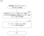
- FIG. 1 is a flow diagram illustrating an example embodiment of a method of the present disclosure.
- FIG. 4 shows an example of a flag management database provided in a database unit of the control device.
- 1 shows an example of application of a communication device according to the present disclosure to a terminal.
- 1 shows an example of a database unit in a terminal.
- 13 shows an example of the operation of a distribution unit in the terminal. 13 shows an example of a de-registration procedure in a terminal and a control device.
- 4 shows an example of a buffer management database provided in a database unit of the control device.
- 1 shows an example of a database unit in a terminal.
- 1 illustrates an example of application of a communication device according to the present disclosure to an access point.
- 1 shows an example of application of a communication device according to the present disclosure to a terminal.
- FIG. 1 is a flow diagram illustrating an example embodiment of a method of the present disclosure.
- (First embodiment) 1 shows an example of a system configuration according to the present disclosure.
- the communication control system according to the present disclosure is a system that executes communication control of communication devices connected to the same network infrastructure.
- the network infrastructure is a wireless network 50
- the communication devices connected to the wireless network 50 are a plurality of terminals 10 and an access point 20.
- the terminal 10 is a terminal device that executes an application.
- the access point 20 is a relay device that relays between the terminal 10 and the communication partner of the terminal 10.
- the access point 20 is connected to the public network via the upper network device 40. This allows multiple terminals 10 to communicate with communication partners such as servers according to their respective applications.
- FIG. 2 shows an example of the configuration of the terminal 10 of this embodiment.
- the terminal 10 has a per-flow buffer unit 13 that accumulates transmission data of a predetermined application 14.
- the application 14 transmits a packet in which the transmission data is stored.
- the terminal 10 uses the per-flow buffer unit 13 and a main signal buffer unit 12 to manage the order of transmission and reception in the main signal transmission and reception unit 11. In this way, the terminal 10 of this embodiment uses different applications 14 and per-flow buffer units 13 for each communication service and network requirements used.
- the terminal 10 is provided with a configuration for controlling transmission for each per-flow buffer unit 13.
- a configuration for controlling transmission for each per-flow buffer unit 13 includes a packet amount notification unit 16 that notifies the amount of packets in the per-flow buffer unit 13, a control signal transmission/reception unit 17 that communicates with the control device 30, and a scheduler unit 15 that schedules packets stored in the per-flow buffer unit 13.
- FIG. 3 shows an example of the configuration of the access point 20.
- the access point 20 has a configuration for performing communication for each application.
- the configuration for performing communication for each application includes a flow-based buffer unit 23 that accumulates packets received by the upper-side main signal transceiver unit 24 for each application 14, and an example is shown in which a main signal buffer unit 22 is used to manage the order of transmission and reception in the lower-side main signal transceiver unit 21.
- the access point 20 is provided with a configuration for control from the control device 30.
- a configuration for control from the control device 30 includes a packet amount notification unit 26 that notifies the amount of packets in the per-flow buffer unit 23, a control signal transmission/reception unit 27 that communicates with the control device 30, and a scheduler unit 25 that schedules the packets stored in the per-flow buffer unit 23.
- FIG. 4 shows an example of the configuration of the control device 30.
- the control device 30 receives the amount of packets transmitted from the control signal transmission/reception units 17 and 27 using the control signal transmission/reception unit 31, and manages the amount of packets in the per-flow buffer units 13 and 23 in the terminal 10 and the access point 20 using a buffer management database provided in the database unit 33.
- the scheduling unit 32 then schedules the packet transmission of the terminal 10 and the access point 20 based on the buffer management database.
- FIG. 5 shows an example of the buffer management database.
- the buffer management database manages the amount of packets for each per-flow buffer unit 13 and 23 provided in the terminal 10 and the access point 20.
- the per-flow buffer units 13 and 23 are identified using the node number, which is the identifier of the terminal 10 and the access point 20, and the buffer number, which is the identifier of the per-flow buffer units 13 and 23.
- the terminal 10 and the access point 20 in this embodiment are provided with unregistered buffer units 52 and 62 that store transmission data other than that of applications. These unregistered buffer units 52 and 62 have unique buffer numbers. This buffer number is arbitrary, but in this embodiment it is described as "unregistered” for ease of understanding.
- the terminal 10 uses the unregistered buffer unit 52 instead of the flow unit buffer unit 13 to be used by the new application 51.
- This configuration in the terminal 10 may be provided in all of the multiple terminals 10, but it is sufficient that at least one of the multiple terminals 10 has the configuration.
- terminal 10#N has the configuration
- the packet is output to the unregistered buffer unit 62.
- the following embodiment shows an example in which the communication control system controls communication for both the terminal 10 and the access point 20. That is, in a wireless network 50 in which multiple terminals 10 are connected to the access point 20, the control device 30 performs quality control for both the multiple terminals 10 and the access point 20 for each of the per-flow buffer units 13 and 23 and for each of the unregistered buffer units 52 and 62.
- FIG. 6 shows an example of a packet transmission flow in the terminal 10.
- an application 14 transmits a packet (S111)
- the packet is stored in the per-flow buffer unit 13 defined for each application 14.
- a new application 51 for which no per-flow buffer unit 13 is defined transmits a packet in step S111
- the packet is allocated to the unregistered buffer unit 52 in step S112.
- the packet amount notification unit 16 notifies the control device 30 of the amount of packets stored in the flow-unit buffer unit 13 and the unregistered buffer unit 52 (S113).
- the terminal 10 then receives the packet transmission time and transmission duration from the control device 30 (S114).
- the scheduler unit 15 of the terminal 10 moves the packets stored in the flow-unit buffer unit 13 and the unregistered buffer unit 52 to the main signal buffer unit 12 according to the packet transmission time and transmission duration notified by the control device 30, and transmits them from the main signal transmission/reception unit 11 (S115).
- FIG. 7 shows an example of a packet transmission flow in the access point 20.
- the upper-side main signal transmitting/receiving unit 24 receives a packet (S121), it distributes the packet to the per-flow buffer units 23#1-#K (S122). At this time, if there is a packet that cannot be distributed to the per-flow buffer units 23#1-#K, it is distributed to the unregistered buffer unit 62.
- the packet amount notifying unit 26 notifies the control device 30 of the packet amount stored in the per-flow buffer units 23#1-#K and the unregistered buffer unit 62 (S123).
- the scheduler unit 25 When the scheduler unit 25 receives the packet transmission time and transmission duration from the control device 30 (S124), it moves the packet stored in the per-flow buffer unit 23 and the unregistered buffer unit 62 to the main signal buffer unit 22 according to the packet transmission time and transmission duration notified from the control device 30, and transmits it from the lower-side main signal transmitting/receiving unit 21 (S125).
- Figure 8 shows an example of a scheduling flow in the control device 30.
- the received packet amount is stored in the buffer management database (S132).
- the buffer numbers of the unregistered buffer units 52 and 62 are entered as "unregistered" based on the buffer management database.
- the scheduling unit 32 determines the transmission time and transmission duration for the terminal 10 and the access point 20 for each buffer number based on the buffer management database (S133). Then, the control signal transmitting/receiving unit 31 notifies the terminal 10 and the access point 20 of the packet transmission time and transmission duration for each buffer number determined by the scheduling unit 32 (S134).
- the terminal 10 and the access point 20 are provided with unregistered buffer units 52 and 62, and the control device 30 also performs scheduling on packets stored in the unregistered buffer units 52 and 62. Therefore, in this embodiment, packet transmission control can be performed even if an application that is not registered in the database unit 33 of the control device 30 exists.
- the method of the present disclosure is executed in the terminal 10 including the per-flow buffer unit 13 and the scheduler unit 15, and the access point 20 including the per-flow buffer unit 23 and the scheduler unit 25.
- the method of the present disclosure is executed by the communication device of the present disclosure, and includes the steps of: A procedure in which the per-flow buffer unit 13 or 23 stores transmission data of a predetermined application; a procedure in which the scheduler unit 15 or 25 controls transmission of the transmission data for each of the per-flow buffer units 13 or 23; a step of deleting the per-flow buffer unit 13 or 23 when the per-flow buffer unit 13 or 23 that is not being used is present in either the communication device of the terminal 10 or the access point 20; Equipped with.
- the terminal 10 includes a counter unit 55.
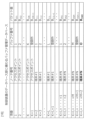
- An example of the counter unit 55 included in the terminal 10#N is shown in FIG. 9.
- the counter unit 55 records the usage time of each flow unit buffer unit 13 for each flow unit buffer unit 13. In this manner, in this embodiment, the usage time of each flow unit buffer unit 13 is managed, and a flow unit buffer unit 13 for which a predetermined time has elapsed since the usage time of the counter unit 55 is determined.
- the operation of the terminal 10 will be described below with reference to FIG. 10.
- the per-flow buffer unit 13#M notifies the packet amount notifying unit 16 of the amount of stored packets (S411).
- the packet amount notifying unit 16 notifies the counter unit 55 of the number #M of the per-flow buffer unit from which the packet amount notification was received and the time of use (S412).
- the counter unit records the notified per-flow buffer unit number #M and the time of use (S413).
- the counter unit 55 determines whether or not there is a per-flow buffer unit 13 that has not been used for a certain period of time (S414). When the per-flow buffer unit 13#M is not being used, the counter unit 55 deletes the per-flow buffer unit 13#M in the terminal 10 (S415).
- step S414 the counter unit 55 sets a time (timer) for determining that each flow unit buffer unit 13 is not in use.
- the counter unit 55 compares the difference between the current time and the time of use with the timer. If the difference is greater than the timer, the flow unit buffer unit 13 with that flow unit buffer number is deleted.
- the access point 20 also includes a counter unit 65 that records the usage time of each per-flow buffer unit 23. As a result, the access point 20, like the terminal 10, deletes a per-flow buffer unit 23 that has been in use for a period of time determined for each application since the usage time of the counter unit 65.
- this embodiment provides the terminal 10 and the access point 20 with counter units 55 and 65, and deletes the per-flow buffer units 13 and 23 that have been in use for a specified period of time. This makes it possible to reduce the load on the terminal 10 in a communication control system that performs quality control on an application-by-application basis.
- the communication control system of this embodiment also includes unregistered buffer units 52 and 62 in the terminal 10 and the access point 20, and the control device 30 also performs scheduling on packets stored in the unregistered buffer units 52 and 62. Therefore, the communication control system of this embodiment can perform packet transmission control even if an application that is not registered in the database unit 33 of the control device 30 exists.
- the application 14 of this embodiment sets a flag for each application and stores it in the packet.
- the flag can be any information that can identify the application. For example, the ToS value in the IP header, the CoS value in the Ethernet frame, the source IP address, the source port number, the destination IP address, the destination port number, the protocol number, or a combination of these can be set as the flag.
- the database 33 of the control device 30 includes a flag management database that manages a list of flags that can be used within the system.
- the flag management database manages the location of the flag in the packet information and the flag value written in that location. For example, if the flag is a ToS value in the IP header, the location of the flag is the ToS field in the IP header, and the flag value is the value written in the ToS field.
- any information about the packet may be included instead of or in addition to the location of the flag in the packet information. In this embodiment, this information is used to determine whether to add per-flow buffer units 13 and 23.
- FIG. 12 shows an example of the configuration of the terminal 10 of this embodiment.
- the terminal 10 includes a database unit 53 and a distribution unit 54.
- the distribution unit 54 performs distribution according to the settings of the database unit 53.
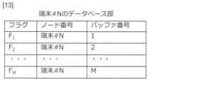
- FIG. 13 shows an example of the database unit 53 in the terminal 10.
- the database unit 53 holds distribution settings to the per-flow buffer unit 13 and the unregistered buffer unit 52 for flags. For example, the database unit 53 sets the node number of the terminal 10 and the buffer numbers of the per-flow buffer unit 13 and the unregistered buffer unit 52 for each flag.
- the allocation unit 54 queries the external control device 30 as to whether or not to add a flow unit buffer unit 13. If the allocation unit 54 receives a response from the control device 30 indicating that a flow unit buffer unit 13 should be added, it adds a flow unit buffer unit 13#M+1 having the buffer number obtained in the response, and links the buffer number of the added flow unit buffer unit 13#M+1 to the new flag in the database unit 53.
- the allocation unit 54 can use the unregistered buffer unit 52 instead of the flow unit buffer unit 13 to be used by the new application 51.
- Figure 14 shows an example of the operation of the distribution unit 54.
- the distribution unit 54 receives a packet (S211), it reads the flag in the packet (S212) and checks in the database unit 53 whether there is a per-flow buffer unit 13 linked to the flag (S213). If the flag is linked to a per-flow buffer unit 13 (Yes in S213), the distribution unit 54 distributes the packet to the per-flow buffer unit 13 returned from the database unit 53 (S214). If the flag in the packet is not registered in the database unit 53 (No in step S213), the distribution unit 54 distributes the packet to the unregistered buffer unit 52 (S215).
- step S213 when the flag in the packet is not registered in the database unit 53 (No in step S213), an unregistered procedure is executed. For example, when new applications 51#1 and 51#2 transmit packets, values corresponding to the flags contained in these packets are not registered in the database unit 53. When transmitting these packets, the communication control system of this embodiment executes the following process.
- FIG. 15 shows an example of an unregistered procedure in the terminal 10 and the control device 30.
- the distribution unit 54 transmits information about a packet that includes a flag that is not registered in the database unit 53 to the control device 30 (S311).
- the control device 30 checks whether the information of the received packet matches the information registered in the flag management database of the database unit 33 (S321). If the information is registered in the flag management database (Yes in step S321), the control device 30 determines to add a per-flow buffer unit 13 (S322).
- step S322 the control device 30 determines the flag and the buffer number of the flow unit buffer unit 13 linked thereto. For example, it determines that a flow unit buffer unit 13 with buffer number O is to be added to flag Fo in terminal 10#N. As a result, buffer number O of terminal 10#N is registered in the buffer management database of database unit 33 shown in FIG. 16. The control device 30 notifies the terminal 10 of the flag and the buffer number of the flow unit buffer unit 13 linked thereto (S323).
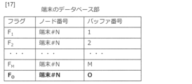
- the distribution unit 54 of the terminal 10 When the distribution unit 54 of the terminal 10 receives the flag and the information on the flow unit buffer unit 13, as shown in FIG. 17, it registers the flag Fo and the buffer number O of the newly created flow unit buffer unit 13 in the database unit 53 (S312). Accordingly, the terminal 10 adds a flow unit buffer unit 13 #M+1 with buffer number O (S312).
- the allocation unit 54 allocates the packet with flag Fo, which has been inquired of by the control device 30, to the per-flow buffer unit 13 with buffer number O (S112). For example, when flag Fo is stored in a packet from new application 51#2, the allocation unit 54 allocates the packet to per-flow buffer unit 13#M+1.
- the subsequent steps are the same as steps S113 to S115.
- control device 30 If the control device 30 does not have a corresponding flag registered in the flag management database (No in step S321), the control device 30 notifies the terminal 10 that the corresponding flag does not exist (S324).
- the distribution unit 54 of the terminal 10 distributes the packet to the unregistered buffer unit 52 (S112), similar to step S215. For example, the distribution unit 54 distributes packets from the new application 51#2 to the unregistered buffer unit 52.
- the subsequent steps are similar to steps S113 to S115.
- the sorting unit 54 may not need to check with the control device 30. In addition, the sorting unit 54 may record information about the packet for which the corresponding flag does not exist in the database unit 53.
- confirmation may be made with the control device 30 for each one, and multiple flow unit buffer units 13 may be newly created.
- FIG. 18 shows an example of the configuration of the access point 20.
- the access point 20 of this embodiment includes a database unit 63 and a distribution unit 64.
- the distribution unit 64 performs distribution according to the settings of the database unit 63, similar to the distribution unit 54. If the packets received by the upper-side main signal transmission/reception unit 24 include a packet of an application that does not correspond to any of the flow unit buffer units 23, the distribution unit 64 outputs the packet to the unregistered buffer unit 62.
- the database unit 63 is similar to the database unit 53 in the terminal 10, and holds allocation settings for the per-flow buffer unit 23 in response to flags. For example, the database unit 63 sets the node number of the access point 20 and the buffer number of the per-flow buffer unit 23 for each flag.
- the allocation unit 64 registers flag information in the database unit 63 based on information from the control device 30, and creates a new per-flow buffer unit 23.
- the communication control system of this embodiment can add a per-flow buffer 13 to each terminal 10 by registering the flags of the applications 14 expected to be executed in each terminal 10 in the flag management database of the database unit 33. Therefore, by adopting this embodiment, it becomes possible to automatically perform quality control for new applications 14 added to the terminal 10. In addition, the number of unregistered buffers in each terminal 10 can be kept to a necessary minimum.
- step S414 shown in FIG. 10 if the difference is greater than the timer, the database unit 53 is notified of that flow unit buffer number #M. Then, in step S415, the database unit 53 deletes the notified flow unit buffer number #M from the database unit 53.
- this embodiment provides the terminal 10 and the access point 20 with counter units 55 and 65, and deletes the entries in the per-flow buffer units 13 and 23 and the corresponding database units 53 and 63 for which a specified time has elapsed since the time of use. This makes it possible to reduce the load on the terminal 10 in a communication control system that performs quality control on an application-by-application basis.
- the terminal 10 may perform a process of terminating the application 14 that has not been used for a certain period of time. Also, the user may manually force-terminate the application 14. Therefore, in this embodiment, as in the second embodiment, the termination of the application 14 is detected, and the information in the per-flow buffer unit 13 and the database unit 53 corresponding to the terminated application 14 is deleted.
- FIG. 19 shows an example of the configuration of the terminal 10 of this embodiment.
- the terminal 10 has a detection unit 56 instead of a counter unit 55.
- the detection unit 56 can be any means capable of detecting the termination of the application 14.
- FIG. 20 shows an example of the operation of the terminal 10 when the new application 51#2 launched in the second embodiment is forcibly terminated.
- the detection unit 56 detects the end of the new application 51#2, it notifies the database unit 53 to delete the information of the unit flow buffer unit 13#M (S421). As a result, the column of the unit flow buffer unit 13#M is deleted from the database unit 53. Furthermore, when the detection unit 56 detects the end of the new application 51#2, it deletes the per-flow buffer unit 13#M (S422).
- the end of the application 14 is detected, and the information in the database unit 53 and the flow unit buffer unit 13 are deleted. This makes it possible to immediately delete unused flow unit buffer units 13 and the information of unused flow unit buffer units 13 in the database unit 53.
- the terminal 10, access point 20, and control device 30 of the present disclosure can also be realized by a computer and a program, and the program can be recorded on a recording medium or provided via a network.
- This disclosure has shown an example in which both the multiple terminals 10 and the access point 20 have an unregistered buffer unit, but the communication control system of this disclosure may be configured so that either the terminal 10 or the access point 20 has an unregistered buffer unit.
- the wireless network 50 can be any communication network available to the terminal 10.
- the access point 20 can be any relay device according to the communication network used by the terminal 10.
- the terminal 10 can be any terminal device that can use a communication network.
- Terminal 11 Main signal transmitting/receiving unit 12, 22: Main signal buffer unit 13, 23: Flow unit buffer unit 14: Application 15, 25: Scheduler unit 16, 26: Packet amount notification unit 17, 27: Control signal transmitting/receiving unit 20: Access point 21: Lower side main signal transmitting/receiving unit 24: Upper side main signal transmitting/receiving unit 30: Control device 31: Control signal transmitting/receiving unit 32: Scheduling unit 33: Database unit 40: Upper network device 50: Wireless network 51: New application 52, 62: Unregistered buffer unit 53, 63: Database unit 54, 64: Distribution unit 55, 65: Counter unit 56: Detection unit
Landscapes
- Engineering & Computer Science (AREA)
- Computer Networks & Wireless Communication (AREA)
- Signal Processing (AREA)
- Data Exchanges In Wide-Area Networks (AREA)
Abstract
本開示は、予予め定められたアプリケーションの送信データを蓄積するフロー単位バッファ部と、前記フロー単位バッファ部ごとに前記送信データの送信制御を行うスケジューラ部と、を備え、使用されていない前記フロー単位バッファ部が存在する場合、その前記フロー単位バッファ部を削除する、通信装置である。
Description
本開示は、アプリケーションごとに通信制御を行う通信制御システムに関する。
近年、同一のネットワーク基盤上に、様々なネットワーク要件をもつ複数の通信サービスを収容する検討が進められている。そのためには、“端末から端末まで”や“端末からアプリケーションサーバまで”のEnd-End区間において、各通信サービスで要求される品質を保証しなければならない。
ネットワークのEnd-Endは、無線と有線の区間に分けることができる。その中でも無線区間では、既存技術としてIEEE802.11のEnhanced Distributed Channel Access(EDCA)と呼ばれる優先制御機能が存在する(例えば、非特許文献1及び2参照。)。
EDCAは端末(宛先)単位での制御であり、同一端末に対してネットワーク要件の異なる複数の通信サービスを提供することはできない。このため、EDCAはアプリケーション単位での品質制御は困難である。そこで、アプリケーション単位のフロー単位バッファ部を設け、フロー単位バッファ部ごとにスケジューリングを行うことで、アプリケーション単位での品質制御を実現可能にするシステムが提案されている(例えば、非特許文献3参照。)。
IEEE 802.11e-2005 - IEEE Standard for Information technology--Local and metropolitan area networks--Specific requirements--Part 11: Wireless LAN Medium Access Control (MAC) and Physical Layer (PHY) Specifications - Amendment 8: Medium Access Control (MAC) Quality of Service Enhancements
QoSを実現する無線LAN規格 IEEE802.11e" 映像情報メディア学会誌 Vol. 57, No. 11 (2003)
無線NWに依存しない集中制御による品質制御技術の提案、坂上裕希、相浦一樹、福井達也、津上諒平、谷口友宏、南勝也、電子情報通信学会総合大会、B-6-5(2021)
非特許文献3では、アプリケーションごとにフロー単位バッファ部を備えることで、アプリケーション単位での品質制御を行うことができる。しかし、端末において使用しうる全てのアプリケーションに対してフロー単位バッファ部を用意すると、端末に負荷が生じる。
そのため本開示では、アプリケーション単位での品質制御を行う通信制御システムにおいて、端末の負荷を軽減することを目的とする。
本開示の通信装置は、
予め定められたアプリケーションの送信データを蓄積するフロー単位バッファ部と、
前記フロー単位バッファ部ごとに前記送信データの送信制御を行うスケジューラ部と、
を備え、
使用されていない前記フロー単位バッファ部が存在する場合、その前記フロー単位バッファ部を削除する。
予め定められたアプリケーションの送信データを蓄積するフロー単位バッファ部と、
前記フロー単位バッファ部ごとに前記送信データの送信制御を行うスケジューラ部と、
を備え、
使用されていない前記フロー単位バッファ部が存在する場合、その前記フロー単位バッファ部を削除する。
本開示の方法は、本開示の通信装置が実行する方法であって、
フロー単位バッファ部が、予め定められたアプリケーションの送信データを蓄積する手順と、
スケジューラ部が、前記フロー単位バッファ部ごとに前記送信データの送信制御を行う手順と、
通信装置が、使用されていない前記フロー単位バッファ部が存在する場合、その前記フロー単位バッファ部を削除する手順と、
を備える。
フロー単位バッファ部が、予め定められたアプリケーションの送信データを蓄積する手順と、
スケジューラ部が、前記フロー単位バッファ部ごとに前記送信データの送信制御を行う手順と、
通信装置が、使用されていない前記フロー単位バッファ部が存在する場合、その前記フロー単位バッファ部を削除する手順と、
を備える。
本開示は、フロー単位バッファ部のなかで使用されていないフロー単位バッファ部が存在する場合、使用されていないフロー単位バッファ部を削除する。これにより、本開示の通信制御システムは、アプリケーション単位での品質制御を行う通信制御システムにおいて、端末の負荷を軽減することができる。
本開示の通信装置では、前記送信データ内のフラグと前記フロー単位バッファ部とを紐づけるデータベース部と、前記送信データ内のフラグに基づき、前記データベース部において紐づけられている前記フロー単位バッファ部に前記送信データを振り分ける振り分け部と、を備え、前記データベース部は、使用されていない前記フロー単位バッファ部が存在する場合、使用されていない前記フロー単位バッファ部の記載を削除してもよい。
本開示の通信装置では、前記予め定められたアプリケーション以外の送信データを蓄積する登録外バッファ部を備え、前記スケジューラ部は、前記フロー単位バッファ部及び前記登録外バッファ部ごとに前記送信データの送信制御を行ってもよい。
本開示の通信装置では、前記フロー単位バッファ部の使用時刻を前記フロー単位バッファ部ごとに記録するカウンタ部を備え、前記カウンタ部の使用時刻から定められた時間を経過した前記フロー単位バッファ部を削除してもよい。
本開示の通信装置では、アプリケーションの終了を検知する検知部を備え、前記検知部において検知されたアプリケーションに対応する前記フロー単位バッファ部を削除してもよい。
本開示の通信制御システムは、本開示の通信装置と、前記通信装置の送信制御を前記フロー単位バッファ部ごとに行う制御装置と、を備える。前記通信装置に備わる前記スケジューラ部は、前記制御装置からの指示に従って、前記フロー単位バッファ部ごとに前記送信データの送信制御を行う。
前記通信装置は、アプリケーションを実行する端末装置でありうる。又、前記通信装置は、前記端末装置と通信相手を中継する中継装置でありうる。
なお、上記各開示は、可能な限り組み合わせることができる。
本開示によれば、アプリケーション単位での品質制御を行う通信制御システムにおいて、端末の負荷を軽減することができる。
以下、本開示の実施形態について、図面を参照しながら詳細に説明する。なお、本開示は、以下に示す実施形態に限定されるものではない。これらの実施の例は例示に過ぎず、本開示は当業者の知識に基づいて種々の変更、改良を施した形態で実施することができる。なお、本明細書及び図面において符号が同じ構成要素は、相互に同一のものを示すものとする。
(第1の実施形態)
図1に、本開示のシステム構成例を示す。本開示の通信制御システムは、同一のネットワーク基盤に接続されている通信装置の通信制御を実行するシステムである。本実施形態では、ネットワーク基盤が無線ネットワーク50であり、無線ネットワーク50に接続されている通信装置が複数の端末10及びアクセスポイント20である例を示す。
図1に、本開示のシステム構成例を示す。本開示の通信制御システムは、同一のネットワーク基盤に接続されている通信装置の通信制御を実行するシステムである。本実施形態では、ネットワーク基盤が無線ネットワーク50であり、無線ネットワーク50に接続されている通信装置が複数の端末10及びアクセスポイント20である例を示す。
端末10はアプリケーションを実行する端末装置である。アクセスポイント20は、端末10と端末10の通信相手とを中継する中継装置である。アクセスポイント20は上位ネットワーク装置40を介して公衆網に接続されている。これにより、複数の端末10はそれぞれアプリケーションに応じたサーバ等の通信相手と通信を行うことができる。
図2に、本実施形態の端末10の構成例を示す。端末10は、予め定められたアプリケーション14の送信データを蓄積するフロー単位バッファ部13を備える。本実施形態では、アプリケーション14が送信データの格納されたパケットを送信する例を示す。また、端末10が、フロー単位バッファ部13と、主信号送受信部11での送受信の順序を管理するために主信号バッファ部12と、を用いる例を示す。このように、本実施形態の端末10は、利用する通信サービスやネットワーク要件ごとに、異なるアプリケーション14及びフロー単位バッファ部13を用いる。
端末10は、フロー単位バッファ部13ごとに送信制御を行うための構成を備える。本実施形態では、フロー単位バッファ部13のパケット量を通知するパケット量通知部16、制御装置30との通信を行う制御信号送受信部17、フロー単位バッファ部13に蓄積されているパケットのスケジューリングを行うスケジューラ部15、を備える例を示す。
図3に、アクセスポイント20の構成例を示す。アクセスポイント20は、アプリケーションごとに通信を行うための構成を備える。本実施形態では、アプリケーションごとに通信を行うための構成として、上位側主信号送受信部24の受信するパケットをアプリケーション14ごとに蓄積するフロー単位バッファ部23を備え、下位側主信号送受信部21での送受信の順序を管理するために主信号バッファ部22を用いる例を示す。
アクセスポイント20は、制御装置30からの制御を行うための構成を備える。本実施形態では、フロー単位バッファ部23のパケット量を通知するパケット量通知部26、制御装置30との通信を行う制御信号送受信部27、フロー単位バッファ部23に蓄積されているパケットのスケジューリングを行うスケジューラ部25、を備える例を示す。
図4に、制御装置30の構成例を示す。制御装置30は、制御信号送受信部31を用いて制御信号送受信部17及び27から送信されたパケット量を受信し、データベース部33に備わるバッファ管理データベースで端末10及びアクセスポイント20におけるフロー単位バッファ部13及び23のパケット量を管理する。そしてスケジューリング部32は、バッファ管理データベースに基づいて、端末10及びアクセスポイント20のパケット送信をスケジューリングする。
図5に、バッファ管理データベースの一例を示す。バッファ管理データベースでは、端末10及びアクセスポイント20に備わるフロー単位バッファ部13及び23ごとのパケット量を管理する。本実施形態では、端末10及びアクセスポイント20の識別子であるノード番号と、フロー単位バッファ部13及び23の識別子であるバッファ番号と、を用いてフロー単位バッファ部13及び23を識別する例を示す。
本実施形態の端末10及びアクセスポイント20は、アプリケーション以外の送信データを蓄積する登録外バッファ部52及び62を備えている。これらの登録外バッファ部52及び62は、固有のバッファ番号を持つ。このバッファ番号は任意であるが、本実施形態では理解が容易になるよう「登録外」と記載する。
端末10に新規アプリケーション51がインストールされたとき、新規アプリケーション51の使用するフロー単位バッファ部13が定められていない。そこで、端末10は、新規アプリケーション51の使用するフロー単位バッファ部13に代えて、登録外バッファ部52を用いる。
端末10におけるこの構成は、複数の端末10のすべてが備わっていてもよいが、複数の端末10のうちの少なくともいずれかが備えていればよい。以下の実施形態では、端末10#Nにこの構成を備える例について説明する。
アクセスポイント20においても、上位側主信号送受信部24の受信したパケットの中に、どのフロー単位バッファ部23にも該当しないアプリケーションのパケットが存在する場合、そのパケットを登録外バッファ部62に出力する。
以下の実施形態では通信制御システムが端末10及びアクセスポイント20の両方の通信制御を行う例を示す。すなわち、複数の端末10がアクセスポイント20に接続されている無線ネットワーク50において、制御装置30が複数の端末10及びアクセスポイント20の両方の品質制御を、フロー単位バッファ部13及び23ごとかつ登録外バッファ部52及び62ごとに実行する例を示す。
図6に、端末10におけるパケット送信フローの一例を示す。アプリケーション14がパケットを送信すると(S111)、アプリケーション14ごとに定められたフロー単位バッファ部13にパケットが蓄積される。手順S111において、フロー単位バッファ部13の定められていない新規アプリケーション51がパケットを送信すると、手順S112において、そのパケットは登録外バッファ部52に振り分けられる。
パケット量通知部16は、フロー単位バッファ部13及び登録外バッファ部52に格納されたパケット量を制御装置30に通知する(S113)。その後、端末10は、パケット送信時刻と送信継続時間を、制御装置30から受信する(S114)。端末10のスケジューラ部15は、制御装置30から通知されたパケット送信時刻及び送信継続時間に従い、フロー単位バッファ部13及び登録外バッファ部52に格納されたパケットを主信号バッファ部12に移動させ、主信号送受信部11から送信する(S115)。
図7に、アクセスポイント20におけるパケット送信フローの一例を示す。上位側主信号送受信部24がパケットを受信すると(S121)、フロー単位バッファ部23#1~#Kにパケットを振り分ける(S122)。このとき、フロー単位バッファ部23#1~#Kに振り分けられないパケットが存在すると、登録外バッファ部62に振り分けられる。パケット量通知部26は、フロー単位バッファ部23#1~#K及び登録外バッファ部62に格納されたパケット量を制御装置30に通知する(S123)。制御装置30からパケット送信時刻と送信継続時間を受信すると(S124)、スケジューラ部25は、制御装置30から通知されたパケット送信時刻及び送信継続時間に従い、フロー単位バッファ部23及び登録外バッファ部62に格納されたパケットを主信号バッファ部22に移動させ、下位側主信号送受信部21から送信する(S125)。
図8に、制御装置30におけるスケジューリングフローの一例を示す。端末10又はアクセスポイント20からパケット量を受信すると(S131)、受信したパケット量をバッファ管理データベースに格納する(S132)。このとき、登録外バッファ部52及び62のパケット量が含まれている場合、登録外バッファ部52及び62のバッファ番号「登録外」を記載する。スケジューリング部32は、バッファ管理データベースに基づいて、端末10及びアクセスポイント20の送信する送信時刻と送信継続時間を、バッファ番号ごとに決定する(S133)。そして、制御信号送受信部31は、スケジューリング部32で決定したバッファ番号ごとのパケット送信時刻と送信継続時間を、端末10及びアクセスポイント20に通知する(S134)。
このように、本実施形態は、端末10及びアクセスポイント20に登録外バッファ部52及び62を備え、制御装置30が登録外バッファ部52及び62に格納されているパケットに対してもスケジューリングを行う。このため、本実施形態は、制御装置30のデータベース部33に登録されていないアプリケーションが存在する場合であっても、パケット送信制御を行うことができる。
ここで、本開示では、フロー単位バッファ部13及びスケジューラ部15を備える端末10、及びフロー単位バッファ部23及びスケジューラ部25を備えるアクセスポイント20において、本開示の方法を実行する。具体的には、本開示の方法は、本開示の通信装置が実行する方法であって、
フロー単位バッファ部13又は23が、予め定められたアプリケーションの送信データを蓄積する手順と、
スケジューラ部15又は25が、前記フロー単位バッファ部13又は23ごとに前記送信データの送信制御を行う手順と、
端末10及びアクセスポイント20のいずれかの通信装置が、使用されていない前記フロー単位バッファ部13又は23が存在する場合、その前記フロー単位バッファ部13又は23を削除する手順と、
を備える。
フロー単位バッファ部13又は23が、予め定められたアプリケーションの送信データを蓄積する手順と、
スケジューラ部15又は25が、前記フロー単位バッファ部13又は23ごとに前記送信データの送信制御を行う手順と、
端末10及びアクセスポイント20のいずれかの通信装置が、使用されていない前記フロー単位バッファ部13又は23が存在する場合、その前記フロー単位バッファ部13又は23を削除する手順と、
を備える。
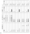
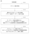
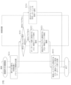
具体的には、端末10はカウンタ部55を備える。端末10#Nに備わるカウンタ部55の一例を図9に示す。カウンタ部55は、フロー単位バッファ部13の使用時刻をフロー単位バッファ部13ごとに記録する。これにより、本実施形態では、各フロー単位バッファ部13の使用時刻を管理し、カウンタ部55の使用時刻から定められた時間を経過したフロー単位バッファ部13を判定する。以下、図10を参照しながら、端末10における動作について説明する。
フロー単位バッファ部13#Mはパケット量通知部16に蓄積したパケット量を通知する(S411)。
パケット量通知部16はカウンタ部55にパケット量通知が来たフロー単位バッファ部の番号#Mと使用時刻を通知する(S412)。
カウンタ部は通知されたフロー単位バッファ部の番号#Mと使用時刻を記録する(S413)。
カウンタ部55は、一定時間使用していないフロー単位バッファ部13があるか否かを判定する(S414)。
カウンタ部55は、フロー単位バッファ部13#Mが使用されていないとき、端末10はフロー単位バッファ部13#Mを削除する(S415)。
パケット量通知部16はカウンタ部55にパケット量通知が来たフロー単位バッファ部の番号#Mと使用時刻を通知する(S412)。
カウンタ部は通知されたフロー単位バッファ部の番号#Mと使用時刻を記録する(S413)。
カウンタ部55は、一定時間使用していないフロー単位バッファ部13があるか否かを判定する(S414)。
カウンタ部55は、フロー単位バッファ部13#Mが使用されていないとき、端末10はフロー単位バッファ部13#Mを削除する(S415)。
ここで、手順S414に関し、カウンタ部55には、図9に示すように、フロー単位バッファ部13ごとに、使用してないと判断する時間(タイマー)を設定する。カウンタ部55は、現在時刻と使用時刻の差と、タイマーを比較する。タイマーよりもその差が大きい場合、そのフロー単位バッファ番号のフロー単位バッファ部13を削除する。
アクセスポイント20においても、図9に示すように、フロー単位バッファ部23の使用時刻をフロー単位バッファ部23ごとに記録するカウンタ部65を備える。これにより、アクセスポイント20も、端末10と同様に、カウンタ部65の使用時刻からアプリケーションごとに定められた時間を経過したフロー単位バッファ部23を削除する。
以上説明したように、本実施形態は、端末10及びアクセスポイント20にカウンタ部55及び65を備え、使用時刻から定められた時間を経過したフロー単位バッファ部13及び23を削除する。これにより、本実施形態は、アプリケーション単位での品質制御を行う通信制御システムにおいて、端末10の負荷を軽減することができる。
また本実施形態の通信制御システムは、端末10及びアクセスポイント20に登録外バッファ部52及び62を備え、制御装置30が登録外バッファ部52及び62に格納されているパケットに対してもスケジューリングを行う。このため、本実施形態態の通信制御システムは、制御装置30のデータベース部33に登録されていないアプリケーションが存在する場合であっても、パケット送信制御を行うことができる。
(第2の実施形態)
本実施形態のアプリケーション14は、アプリケーション毎にフラグを設定し、パケットの中に格納する。フラグは、アプリケーションを識別可能な任意の情報を用いることができる。例えば、IPヘッダ内のToS値、イーサネットフレーム内のCoS値、送信元IPアドレス、送信元ポート番号、宛先IPアドレス、宛先ポート番号、プロトコル番号のほか、これらの組み合わせなどをフラグとして設定できる。
本実施形態のアプリケーション14は、アプリケーション毎にフラグを設定し、パケットの中に格納する。フラグは、アプリケーションを識別可能な任意の情報を用いることができる。例えば、IPヘッダ内のToS値、イーサネットフレーム内のCoS値、送信元IPアドレス、送信元ポート番号、宛先IPアドレス、宛先ポート番号、プロトコル番号のほか、これらの組み合わせなどをフラグとして設定できる。
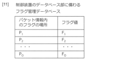
制御装置30のデータベース33は、システム内において使用されうるフラグの一覧を管理するフラグ管理データベースを備える。フラグ管理データベースには、図11に示すように、パケット情報内のフラグの場所と、その場所に記載されているフラグ値と、を管理する。例えば、フラグがIPヘッダ内のToS値であれば、フラグの場所はIPヘッダ内のToSフィールドであり、フラグ値はToSフィールドに記載されている値である。ここで、パケット情報内のフラグの場所に代えて、又はこれと共に、パケットの任意の情報を含みうる。本実施形態では、これらの情報を用いて、フロー単位バッファ部13及び23を追加するか否かを判定する。
図12に、本実施形態の端末10の構成例を示す。端末10は、第1の実施形態の構成に加え、データベース部53及び振り分け部54を備える。振り分け部54は、データベース部53の設定に従って振り分けを行う。図13に、端末10におけるデータベース部53の一例を示す。データベース部53は、フラグに対するフロー単位バッファ部13及び登録外バッファ部52への振り分け設定を保持する。例えば、データベース部53は、端末10のノード番号と、フロー単位バッファ部13及び登録外バッファ部52のバッファ番号と、をフラグごとに設定する。
振り分け部54は、データベース部53に定めのない新たなフラグが存在する場合、フロー単位バッファ部13を追加するか否を外部の制御装置30に問い合わせる。そして、振り分け部54は、フロー単位バッファ部13を追加する旨の回答が制御装置30から得られた場合、前記回答で得られたバッファ番号を有するフロー単位バッファ部13#M+1を追加し、前記追加したフロー単位バッファ部13#M+1のバッファ番号と前記新たなフラグとをデータベース部53において紐づける。
端末10に新規アプリケーション51がインストールされたとき、新規アプリケーション51の使用するフロー単位バッファ部13が定められていない。そこで、振り分け部54は、新規アプリケーション51の使用するフロー単位バッファ部13に代えて、登録外バッファ部52を用いることができる。
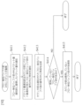
図14に、振り分け部54の動作の一例を示す。振り分け部54は、パケットを受信すると(S211)、パケット内のフラグを読み出し(S212)、フラグに紐づけられているフロー単位バッファ部13があるかをデータベース部53で確認する(S213)。フラグに対してフロー単位バッファ部13の紐づけがあるとき(S213においてYes)、振り分け部54は、パケットをデータベース部53から返ってきたフロー単位バッファ部13へ振り分ける(S214)。パケット内のフラグがデータベース部53に登録されていないとき(手順S213においてNo)、振り分け部54は、登録外バッファ部52にパケットを振り分ける(S215)。
本実施形態では、手順S213において、パケット内のフラグがデータベース部53に登録されていないとき(手順S213においてNo)、登録外手順を実行する。例えば、新規アプリケーション51#1及び51#2がパケットを送信した場合、これらのパケットに含まれるフラグに相当する値はデータベース部53に登録されていない。これらのパケットの送信に際し、本実施形態の通信制御システムは、以下の処理を実行する。
図15に、端末10及び制御装置30における登録外手順の一例を示す。振り分け部54は、データベース部53に登録されていないフラグを含むパケットの情報を、制御装置30へ送信する(S311)。
制御装置30は、受信したパケットの情報がデータベース部33のフラグ管理データベースに登録されている情報と一致するかを確認する(S321)。フラグ管理データベースに登録されている場合(手順S321においてYes)、制御装置30は、フロー単位バッファ部13を追加すると判定する(S322)。
手順S322では、制御装置30は、フラグとこれに紐づけられるフロー単位バッファ部13のバッファ番号を定める。例えば、端末10#NにおいてフラグFoに対してバッファ番号Oのフロー単位バッファ部13を追加すると定める。これにより、図16に示すデータベース部33のバッファ管理データベースに、端末10#Nのバッファ番号Oが登録される。制御装置30は、フラグとこれに紐づけられるフロー単位バッファ部13のバッファ番号を端末10に通知する(S323)。
端末10の振り分け部54は、フラグ及びフロー単位バッファ部13の情報を受信すると、図17に示すように、データベース部53にフラグFoと新設するフロー単位バッファ部13のバッファ番号Oを登録する(S312)。これに伴い、端末10は、バッファ番号Oのフロー単位バッファ部13#M+1を追加する(S312)。
振り分け部54は、制御装置30に問い合わせたフラグFoのパケットを、バッファ番号Oのフロー単位バッファ部13に振り分ける(S112)。例えば、新規アプリケーション51#2からのパケットにフラグFoが格納されているとき、振り分け部54は、フロー単位バッファ部13#M+1に振り分ける。これ以降の手順は、手順S113~S115と同様である。
なお、制御装置30において、フラグ管理データベースに該当するフラグが登録されていない場合(手順S321においてNo)、制御装置30は、該当するフラグが存在しないことを端末10へ通知する(S324)。この場合、端末10の振り分け部54は、手順S215と同様に、登録外バッファ部52にパケットを振り分ける(S112)。例えば、振り分け部54は、新規アプリケーション51#2からのパケットを、登録外バッファ部52に振り分ける。これ以降の手順は、手順S113~S115と同様である。
振り分け部54は、手順S324において該当するフラグが存在しないことを通知されたパケットと同様のパケットが再度到来した場合、制御装置30へ確認しなくてもよい。また、該当するフラグが存在しないパケット情報をデータベース部53に記録してもよい。
複数の新規アプリケーションが存在する場合、それぞれに対して制御装置30へ確認を実施し、複数のフロー単位バッファ部13を新設してもよい。
図18に、アクセスポイント20の構成例を示す。本実施形態のアクセスポイント20は、第1の実施形態の構成に加え、データベース部63及び振り分け部64を備える。振り分け部64は、振り分け部54と同様に、データベース部63の設定に従って振り分けを行う。上位側主信号送受信部24の受信したパケットの中に、どのフロー単位バッファ部23にも該当しないアプリケーションのパケットが存在する場合、振り分け部64は、そのパケットを登録外バッファ部62に出力する。
データベース部63は、端末10におけるデータベース部53と同様であり、フラグに対するフロー単位バッファ部23の振り分け設定を保持する。例えば、データベース部63は、アクセスポイント20のノード番号と、フロー単位バッファ部23のバッファ番号と、をフラグごとに設定する。振り分け部64は、制御装置30からの情報に基づき、データベース部63にフラグの情報を登録し、フロー単位バッファ部23を新設する。
このように、本実施形態の通信制御システムは、各端末10において実行することの予想されるアプリケーション14のフラグをデータベース部33のフラグ管理データベースに登録することで、各端末10にフロー単位バッファ13を追加することができる。このため、本実施形態を採用することで、端末10において追加される新規のアプリケーション14に対し、自動で品質制御を行うことが可能になる。また、各端末10における登録外バッファの数を必要最小限にすることができる。
ここで、本実施形態では、図10に示す手順S414に関し、タイマーよりもその差が大きい場合は、データベース部53のそのフロー単位バッファ番号#Mを通知する。すると、手順S415において、データベース部53は、通知されたフロー単位バッファ番号#Mをデータベース部53から削除する。
以上説明したように、本実施形態は、端末10及びアクセスポイント20にカウンタ部55及び65を備え、使用時刻から定められた時間を経過したフロー単位バッファ部13及び23と、それに該当するデータベース部53及び63の記載を削除する。これにより、本実施形態は、アプリケーション単位での品質制御を行う通信制御システムにおいて、端末10の負荷を軽減することができる。
(第3の実施形態)
端末10の負荷を軽減するため、端末10は、起動中のアプリケーション14のなかで一定時間使用しないものが存在する場合、一定時間使用しないアプリケーション14を終了する処理を行うことがある。また、ユーザの手でアプリケーション14を強制終了することもある。そこで、本実施形態では、第2の実施形態において、アプリケーション14の終了を検知し、終了したアプリケーション14に対応するフロー単位バッファ部13及びデータベース部53の情報を削除する。
端末10の負荷を軽減するため、端末10は、起動中のアプリケーション14のなかで一定時間使用しないものが存在する場合、一定時間使用しないアプリケーション14を終了する処理を行うことがある。また、ユーザの手でアプリケーション14を強制終了することもある。そこで、本実施形態では、第2の実施形態において、アプリケーション14の終了を検知し、終了したアプリケーション14に対応するフロー単位バッファ部13及びデータベース部53の情報を削除する。
図19に、本実施形態の端末10の構成例を示す。端末10は、カウンタ部55に代えて検知部56を備える。検知部56は、アプリケーション14の終了を検知しうる任意の手段でありうる。
図20に、第2の実施形態で起動した新規アプリケーション51#2を強制終了したときの端末10の動作の一例を示す。
検知部56は、新規アプリケーション51#2の終了を検知すると、フロー単位バッファ部13#Mの情報削除をデータベース部53に通知する(S421)。これにより、データベース部53からフロー単位バッファ部13#Mの欄が削除される。
また検知部56は、新規アプリケーション51#2の終了を検知すると、フロー単位バッファ部13#Mを削除する(S422)。
検知部56は、新規アプリケーション51#2の終了を検知すると、フロー単位バッファ部13#Mの情報削除をデータベース部53に通知する(S421)。これにより、データベース部53からフロー単位バッファ部13#Mの欄が削除される。
また検知部56は、新規アプリケーション51#2の終了を検知すると、フロー単位バッファ部13#Mを削除する(S422)。
以上説明したように、本実施形態では、アプリケーション14の終了を検知し、データベース部53の情報およびフロー単位バッファ部13の削除を実施する。これにより、使用しないフロー単位バッファ部13と、データベース部53における使用しないフロー単位バッファ部13の情報を即座に削除することができる。
(その他の実施形態)
本開示の端末10、アクセスポイント20、及び制御装置30は、コンピュータとプログラムによっても実現でき、プログラムを記録媒体に記録することも、ネットワークを通して提供することも可能である。
本開示の端末10、アクセスポイント20、及び制御装置30は、コンピュータとプログラムによっても実現でき、プログラムを記録媒体に記録することも、ネットワークを通して提供することも可能である。
本開示は、複数の端末10及びアクセスポイント20の両方が登録外バッファ部を備える例を示したが、本開示の通信制御システムは、端末10及びアクセスポイント20のいずれか一方に登録外バッファ部を備えていればよい。
また、無線ネットワーク50は端末10の利用可能な任意の通信ネットワークでありうる。アクセスポイント20は、端末10の利用する通信ネットワークに応じた任意の中継装置でありうる。端末10は、通信ネットワークを利用可能な任意の端末装置でありうる。
10:端末
11:主信号送受信部
12、22:主信号バッファ部
13、23:フロー単位バッファ部
14:アプリケーション
15、25:スケジューラ部
16、26:パケット量通知部
17、27:制御信号送受信部
20:アクセスポイント
21:下位側主信号送受信部
24:上位側主信号送受信部
30:制御装置
31:制御信号送受信部
32:スケジューリング部
33:データベース部
40:上位ネットワーク装置
50:無線ネットワーク
51:新規アプリケーション
52、62:登録外バッファ部
53、63:データベース部
54、64:振り分け部
55、65:カウンタ部
56:検知部
11:主信号送受信部
12、22:主信号バッファ部
13、23:フロー単位バッファ部
14:アプリケーション
15、25:スケジューラ部
16、26:パケット量通知部
17、27:制御信号送受信部
20:アクセスポイント
21:下位側主信号送受信部
24:上位側主信号送受信部
30:制御装置
31:制御信号送受信部
32:スケジューリング部
33:データベース部
40:上位ネットワーク装置
50:無線ネットワーク
51:新規アプリケーション
52、62:登録外バッファ部
53、63:データベース部
54、64:振り分け部
55、65:カウンタ部
56:検知部
Claims (8)
- 予め定められたアプリケーションの送信データを蓄積するフロー単位バッファ部と、
前記フロー単位バッファ部ごとに前記送信データの送信制御を行うスケジューラ部と、
を備え、
使用されていない前記フロー単位バッファ部が存在する場合、その前記フロー単位バッファ部を削除する、
通信装置。 - 前記送信データ内のフラグと前記フロー単位バッファ部とを紐づけるデータベース部と、
前記送信データ内のフラグに基づき、前記データベース部において紐づけられている前記フロー単位バッファ部に前記送信データを振り分ける振り分け部と、
を備え、
前記データベース部は、使用されていない前記フロー単位バッファ部が存在する場合、使用されていない前記フロー単位バッファ部の記載を削除する、
請求項1に記載の通信装置。 - 前記予め定められたアプリケーション以外の送信データを蓄積する登録外バッファ部を備え、
前記スケジューラ部は、前記フロー単位バッファ部及び前記登録外バッファ部ごとに前記送信データの送信制御を行う、
請求項1に記載の通信装置。 - 前記フロー単位バッファ部の使用時刻を前記フロー単位バッファ部ごとに記録するカウンタ部を備え、
前記カウンタ部の使用時刻から定められた時間を経過した前記フロー単位バッファ部を削除する、
請求項1に記載の通信装置。 - アプリケーションの終了を検知する検知部を備え、
前記検知部において検知されたアプリケーションに対応する前記フロー単位バッファ部を削除する、
請求項1に記載の通信装置。 - 請求項1から5のいずれかに記載の通信装置と、
前記通信装置の送信制御を前記フロー単位バッファ部ごとに行う制御装置と、
を備え、
前記通信装置に備わる前記スケジューラ部は、前記制御装置からの指示に従って、前記フロー単位バッファ部ごとに前記送信データの送信制御を行う、
通信制御システム。 - 前記通信装置は、アプリケーションを実行する端末装置、又は前記端末装置と通信相手を中継する中継装置である、
請求項6に記載の通信制御システム。 - フロー単位バッファ部が、予め定められたアプリケーションの送信データを蓄積する手順と、
スケジューラ部が、前記フロー単位バッファ部ごとに前記送信データの送信制御を行う手順と、
通信装置が、使用されていない前記フロー単位バッファ部が存在する場合、その前記フロー単位バッファ部を削除する手順と、
を備える方法。
Priority Applications (2)
| Application Number | Priority Date | Filing Date | Title |
|---|---|---|---|
| PCT/JP2023/022426 WO2024257340A1 (ja) | 2023-06-16 | 2023-06-16 | 通信制御システム |
| JP2025527187A JPWO2024257340A1 (ja) | 2023-06-16 | 2023-06-16 |
Applications Claiming Priority (1)
| Application Number | Priority Date | Filing Date | Title |
|---|---|---|---|
| PCT/JP2023/022426 WO2024257340A1 (ja) | 2023-06-16 | 2023-06-16 | 通信制御システム |
Publications (1)
| Publication Number | Publication Date |
|---|---|
| WO2024257340A1 true WO2024257340A1 (ja) | 2024-12-19 |
Family
ID=93851691
Family Applications (1)
| Application Number | Title | Priority Date | Filing Date |
|---|---|---|---|
| PCT/JP2023/022426 Ceased WO2024257340A1 (ja) | 2023-06-16 | 2023-06-16 | 通信制御システム |
Country Status (2)
| Country | Link |
|---|---|
| JP (1) | JPWO2024257340A1 (ja) |
| WO (1) | WO2024257340A1 (ja) |
Citations (2)
| Publication number | Priority date | Publication date | Assignee | Title |
|---|---|---|---|---|
| JP2021170814A (ja) * | 2017-11-10 | 2021-10-28 | 日本電気株式会社 | サーバ装置及びサーバ装置の方法 |
| WO2023067768A1 (ja) * | 2021-10-21 | 2023-04-27 | 日本電信電話株式会社 | 制御システム、制御方法、コントローラ、及びプログラム |
-
2023
- 2023-06-16 JP JP2025527187A patent/JPWO2024257340A1/ja active Pending
- 2023-06-16 WO PCT/JP2023/022426 patent/WO2024257340A1/ja not_active Ceased
Patent Citations (2)
| Publication number | Priority date | Publication date | Assignee | Title |
|---|---|---|---|---|
| JP2021170814A (ja) * | 2017-11-10 | 2021-10-28 | 日本電気株式会社 | サーバ装置及びサーバ装置の方法 |
| WO2023067768A1 (ja) * | 2021-10-21 | 2023-04-27 | 日本電信電話株式会社 | 制御システム、制御方法、コントローラ、及びプログラム |
Also Published As
| Publication number | Publication date |
|---|---|
| JPWO2024257340A1 (ja) | 2024-12-19 |
Similar Documents
| Publication | Publication Date | Title |
|---|---|---|
| CN112889254B (zh) | 使用策略处理数据包的方法和系统 | |
| CN113302880B (zh) | 用于支持局域网(lan)的方法和装置 | |
| CN111758279B (zh) | 跟踪QoS违规事件 | |
| EP1021015B1 (en) | System for policy-based network configuration | |
| WO2020155940A1 (zh) | 一种通信方法及通信装置 | |
| CN112586040B (zh) | 选择移动网络运营商的方法、电信网络、可读存储介质 | |
| CN113228562B (zh) | 针对检测和执行规则集合处理预配置简档的功能和方法 | |
| WO2018066977A1 (ko) | 네트워크 슬라이스를 지원하는 로밍 환경에서의 단말의 어태치 및 홈 라우팅된 pdu 세션의 생성을 위한 방법 및 장치 | |
| JP2023504763A (ja) | QoSマッピング | |
| WO2016105010A1 (ko) | 이동 통신 시스템에서 전송 차별화를 제공하는 방법 및 장치 | |
| US9130848B2 (en) | Method and apparatus for enhancing QoS during home network remote access | |
| US20240306031A1 (en) | Method for data traffic correlation and transmission | |
| WO2021235769A1 (ko) | 이동통신 네트워크에서 단말에 deterministic communication을 지원하는 방법 및 장치 | |
| WO2024235251A1 (zh) | 网络管理方法、通信装置、及存储介质 | |
| US11849351B2 (en) | Removal of application identifier | |
| WO2013151252A1 (ko) | 무선 통신망의 이용요건을 변경하면서 복수 이종망들을 이용하는 방법 및 장치 | |
| US8059598B2 (en) | Wireless communication system and method for managing service flow identifier in the same | |
| WO2024241413A1 (ja) | 通信制御システム | |
| CN115665822B (zh) | 流量异常处理方法、装置、用户面功能实体及存储介质 | |
| JP2017126955A (ja) | 情報処理装置、情報処理方法、およびプログラム | |
| JP2003516040A (ja) | 移動電気通信網内のエラー報告 | |
| JP2008524959A (ja) | 多層wlanにおける無線バックホールの方法 | |
| JP7790598B2 (ja) | 無線通信システム | |
| JP7552861B2 (ja) | 制御システム、制御方法、コントローラ、及びプログラム | |
| JP6829290B2 (ja) | 情報処理装置及び情報処理方法 |
Legal Events
| Date | Code | Title | Description |
|---|---|---|---|
| 121 | Ep: the epo has been informed by wipo that ep was designated in this application |
Ref document number: 23941642 Country of ref document: EP Kind code of ref document: A1 |
|
| ENP | Entry into the national phase |
Ref document number: 2025527187 Country of ref document: JP Kind code of ref document: A |
|
| WWE | Wipo information: entry into national phase |
Ref document number: 2025527187 Country of ref document: JP |
|
| NENP | Non-entry into the national phase |
Ref country code: DE |