WO2024257217A1 - 無線送信装置、無線受信装置、無線中継装置、制御回路、記憶媒体、通信システムおよび通信方法 - Google Patents
無線送信装置、無線受信装置、無線中継装置、制御回路、記憶媒体、通信システムおよび通信方法 Download PDFInfo
- Publication number
- WO2024257217A1 WO2024257217A1 PCT/JP2023/021912 JP2023021912W WO2024257217A1 WO 2024257217 A1 WO2024257217 A1 WO 2024257217A1 JP 2023021912 W JP2023021912 W JP 2023021912W WO 2024257217 A1 WO2024257217 A1 WO 2024257217A1
- Authority
- WO
- WIPO (PCT)
- Prior art keywords
- wireless
- signal
- wired
- control signal
- communication
- Prior art date
- Legal status (The legal status is an assumption and is not a legal conclusion. Google has not performed a legal analysis and makes no representation as to the accuracy of the status listed.)
- Ceased
Links
Images


Classifications
-
- H—ELECTRICITY
- H04—ELECTRIC COMMUNICATION TECHNIQUE
- H04B—TRANSMISSION
- H04B1/00—Details of transmission systems, not covered by a single one of groups H04B3/00 - H04B13/00; Details of transmission systems not characterised by the medium used for transmission
- H04B1/38—Transceivers, i.e. devices in which transmitter and receiver form a structural unit and in which at least one part is used for functions of transmitting and receiving
- H04B1/40—Circuits
-
- H—ELECTRICITY
- H04—ELECTRIC COMMUNICATION TECHNIQUE
- H04B—TRANSMISSION
- H04B17/00—Monitoring; Testing
- H04B17/30—Monitoring; Testing of propagation channels
- H04B17/309—Measuring or estimating channel quality parameters
-
- H—ELECTRICITY
- H04—ELECTRIC COMMUNICATION TECHNIQUE
- H04L—TRANSMISSION OF DIGITAL INFORMATION, e.g. TELEGRAPHIC COMMUNICATION
- H04L25/00—Baseband systems
- H04L25/02—Details ; arrangements for supplying electrical power along data transmission lines
-
- H—ELECTRICITY
- H04—ELECTRIC COMMUNICATION TECHNIQUE
- H04L—TRANSMISSION OF DIGITAL INFORMATION, e.g. TELEGRAPHIC COMMUNICATION
- H04L27/00—Modulated-carrier systems
- H04L27/18—Phase-modulated carrier systems, i.e. using phase-shift keying
- H04L27/20—Modulator circuits; Transmitter circuits
- H04L27/2032—Modulator circuits; Transmitter circuits for discrete phase modulation, e.g. in which the phase of the carrier is modulated in a nominally instantaneous manner
- H04L27/2053—Modulator circuits; Transmitter circuits for discrete phase modulation, e.g. in which the phase of the carrier is modulated in a nominally instantaneous manner using more than one carrier, e.g. carriers with different phases
- H04L27/206—Modulator circuits; Transmitter circuits for discrete phase modulation, e.g. in which the phase of the carrier is modulated in a nominally instantaneous manner using more than one carrier, e.g. carriers with different phases using a pair of orthogonal carriers, e.g. quadrature carriers
-
- H—ELECTRICITY
- H04—ELECTRIC COMMUNICATION TECHNIQUE
- H04L—TRANSMISSION OF DIGITAL INFORMATION, e.g. TELEGRAPHIC COMMUNICATION
- H04L27/00—Modulated-carrier systems
- H04L27/32—Carrier systems characterised by combinations of two or more of the types covered by groups H04L27/02, H04L27/10, H04L27/18 or H04L27/26
- H04L27/34—Amplitude- and phase-modulated carrier systems, e.g. quadrature-amplitude modulated carrier systems
-
- H—ELECTRICITY
- H04—ELECTRIC COMMUNICATION TECHNIQUE
- H04L—TRANSMISSION OF DIGITAL INFORMATION, e.g. TELEGRAPHIC COMMUNICATION
- H04L43/00—Arrangements for monitoring or testing data switching networks
- H04L43/14—Arrangements for monitoring or testing data switching networks using software, i.e. software packages
-
- H—ELECTRICITY
- H04—ELECTRIC COMMUNICATION TECHNIQUE
- H04W—WIRELESS COMMUNICATION NETWORKS
- H04W28/00—Network traffic management; Network resource management
- H04W28/02—Traffic management, e.g. flow control or congestion control
- H04W28/04—Error control
-
- H—ELECTRICITY
- H04—ELECTRIC COMMUNICATION TECHNIQUE
- H04W—WIRELESS COMMUNICATION NETWORKS
- H04W28/00—Network traffic management; Network resource management
- H04W28/02—Traffic management, e.g. flow control or congestion control
- H04W28/06—Optimizing the usage of the radio link, e.g. header compression, information sizing, discarding information
Definitions
- This disclosure relates to a wireless transmitting device, a wireless receiving device, a wireless relay device, a control circuit, a storage medium, a communication system, and a communication method for making part of wired communication wireless.
- Patent Document 1 discloses a technology for converting wired signals into millimeter waves for wireless transmission. Millimeter waves are suitable for high-capacity, low-latency wireless transmission because they are less likely to interfere with other communications due to their high line-propagation properties and because it is easy to secure a wide bandwidth.
- the above conventional technology only discloses a method of remodulating a wired signal into a wireless bit pattern and transmitting it, and there is a problem in that it is not possible to perform communication management such as measuring communication quality or adjusting communication rates in the wireless transmission section.
- the present disclosure has been made in consideration of the above, and aims to obtain a wireless transmission device that enables communication management in a wireless transmission section in which part of the wired communication is wirelessized.
- the wireless transmission device disclosed herein is characterized by comprising a wired receiving unit that receives a wired signal that is a signal transmitted by wire and is composed of a plurality of frames, a wireless control signal providing unit that inserts a wireless control signal, which is a control signal for managing wireless communication, into a section where no information transmission is taking place between frames of the received wired signal, and a wireless signal generating unit that generates a wireless signal to be transmitted wirelessly using the received bit pattern of the wired signal and the wireless control signal.
- the wireless transmission device disclosed herein has the effect of enabling communication management in a wireless transmission section where part of the wired communication is made wireless.
- FIG. 1 is a diagram showing a functional configuration of a wireless transmission device according to a first embodiment
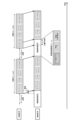
- FIG. 1 illustrates a wired signal received by a wireless transmission device and a wireless signal transmitted by the wireless transmission device when an Ethernet frame is used.
- FIG. 1 is a diagram showing a functional configuration of a wireless receiving device according to a first embodiment
- FIG. 1 illustrates an example of the configuration of a communication system including a wireless transmitting device and a wireless receiving device.
- FIG. 1 shows an example of the configuration of a communication system including a wireless transmitting device, a wireless receiving device, and a wireless relay device.
- FIG. 13 is a diagram showing a functional configuration of a wireless relay device according to a second embodiment.
- FIG. 1 is a diagram showing an example of the configuration of a communication system including a communication device having a bidirectional communication function.
- FIG. 1 shows an example of a hardware configuration.
- wireless transmitting device wireless receiving device
- wireless relay device control circuit, storage medium, communication system, and communication method according to the embodiments of the present disclosure are described in detail with reference to the drawings.
- Embodiment 1. 1 is a diagram illustrating a functional configuration of a wireless transmission device 1 according to a first embodiment.
- the wireless transmission device 1 is an example of a communication device having a function of receiving a wired signal, which is a signal transmitted by a wire, and a function of converting the wired signal into a wireless signal and wirelessly transmitting the wireless signal.
- the wireless transmitting device 1 has wired receiving units 101A and 101B, a wired signal detection unit 102, a wireless control signal providing unit 103, a wireless signal generating unit 104, a wireless transmitting unit 105, and a transmitting antenna unit 106.
- the wired receiving units 101A and 101B each perform similar processing, hereinafter, when there is no need to particularly distinguish between the wired receiving unit 101A and the wired receiving unit 101B, they may be simply referred to as the wired receiving unit 101.
- the signal system of the wired signal received by the wired receiving unit 101A is referred to as signal system #A
- the signal system of the wired signal received by the wired receiving unit 101B is referred to as signal system #B.
- the wired receiver 101 receives a wired signal.
- the wired receiver 101 performs wired communication according to a communication method such as Ethernet (registered trademark), RS-232C, RS-422, or RS-485. All of these communication methods perform burst transmission in which frames are treated as a single block of wired communication.
- the wired receiver 101 generates demodulated data of the received wired signal and outputs the bit string of the generated demodulated data to both the wired signal detector 102 and the wireless signal generator 104.
- the wired signal detection unit 102 detects a section where no information is transmitted between frames of the wired signal received by the wired receiving unit 101.
- the wired signal detection unit 102 outputs information indicating the detected section to the wireless control signal providing unit 103.
- FIG. 2 is a diagram showing a wired signal received by the wireless transmission device 1 and a wireless signal transmitted by the wireless transmission device 1 when an Ethernet frame is used.
- the wired signal received by the wireless transmission device 1 is composed of multiple wired frames.
- Each wired frame can include a preamble, a header, a payload, and a checksum.
- the wired frame is an Ethernet frame.
- SFD Start Frame Delimiter
- the presence of an Ethernet frame is recognized by using a predetermined bit pattern called an SFD (Start Frame Delimiter) present in the preamble or in the header received following the preamble as a marker, and the payload in the Ethernet frame is decoded and the payload data is handed over to a higher layer.
- SFD Start Frame Delimiter
- guard time section Between frames, there is a guard time section called an IPG (Inter Packet Gap) or IFG (Inter Frame Gap).
- IPG Inter Packet Gap
- IFG Inter Frame Gap
- a synchronization signal between transmission and reception may be transmitted in the wired physical layer.
- the guard time section which is the synchronization signal, is passed to the function responsible for the MAC (Media Access Control) layer, so from the perspective of the MAC layer, this guard time section is judged to be a section where there is no signal, in other words, a section where no information is being transmitted.
- a chunk of data surrounded by a start bit and a stop bit is transmitted as one burst, and there is a guard time interval from the stop bit to the next start bit during which no information is transmitted.
- the wired signal detection unit 102 outputs information indicating a section where no information transmission occurs between frames of the wired signal as described above to the wireless control signal providing unit 103.
- the "information indicating a section where no information transmission occurs between frames of the wired signal" may be, for example, information indicating a section where a wired burst exists, and a section other than a section where a wired burst exists may be determined to be a "section where no information transmission occurs between frames of the wired signal".
- the wireless control signal providing unit 103 inserts a wireless control signal, which is a control signal for wireless communication, into a section where no information transmission is taking place between frames of a wired signal.
- the wireless control signal is composed of one or more wireless control information frames.
- the wireless control information frame includes a wireless preamble, a wireless header, and wireless control information. Note that although it has been stated that a wireless control signal is inserted into a section where no information transmission is taking place, if the wired signal includes a long preamble such as an Ethernet frame and includes information in the header such as an SFD that indicates the start position of the frame body, as shown in FIG. 2, a part of the preamble of the wired frame may be overwritten with the wireless control signal.
- the wireless signal includes information included in the wired frame of the wired signal and the wireless control signal, and in the example shown in FIG. 2, a part of the preamble of wired frame #2 is overwritten with the wireless control signal. In this case, it becomes possible to transmit a wireless control signal that is longer than the guard time section by the length of the overwrite section. If part of the preamble of a wired frame is overwritten with a wireless control signal, a valid wired signal can be restored by re-adding the preamble to the beginning when the SFD is received on the receiving side.
- the wireless signal generating unit 104 generates a wireless signal to be wirelessly transmitted by the wireless transmitting unit 105 using the reception bit pattern of the wired signal received by the wired receiving unit 101 and the wireless control signal inserted by the wireless control signal adding unit 103.
- the wireless signal generating unit 104 outputs the generated wireless signal to the wireless transmitting unit 105.
- the wireless transmission unit 105 wirelessly transmits the wireless signal generated by the wireless signal generation unit 104 via the transmission antenna unit 106.
- the wireless signal transmitted from the wireless transmission device 1 has a wireless control signal inserted in the section where no information is transmitted between the wired frames of the wired signal, as shown in FIG. 2.
- Ethernet frames often have an error detection function called FCS (Frame Check Sequence) using CRC (Cyclic Redundancy Check).
- FCS Full Check Sequence
- CRC Cyclic Redundancy Check
- the wireless transmission device 1 does not necessarily need to perform a CRC check to remove frames in which errors are detected. This is because if all frames are received before the CRC calculation is completed and then a decision is made as to whether to send the frame before sending it to a later stage, the amount of delay will be large.
- the CRC check can be performed by a communication device that performs upper layer processing, and error detection does not need to be performed in a device that relays and transfers Ethernet frames, etc. equivalently as they are, such as the wireless transmission device 1.
- radio control information included in a radio control signal is a known sequence for channel estimation, such as BPSK (Binary Phase Shift Keying), which is necessary for synchronous detection. If the phase rotation amount of the known sequence can be corrected on the receiving side, synchronous detection can be realized, and signal multiplexing using QPSK (Quadrature Phase Shift Keying) or spreading codes, which will be described later, can also be realized. Furthermore, by transmitting a known sequence as radio control information, it becomes possible to measure the signal level and noise level based on the reception result of the known sequence, and it is also possible to use adaptive modulation that uses a modulation method according to the reception environment.
- BPSK Binary Phase Shift Keying
- reception SNR Signal-to-Noise Ratio
- a noise-resistant modulation method such as BPSK or binary ASK can be used, and if the reception SNR exceeds the threshold, multi-value transmission can be performed.
- transmission parameters such as the modulation method can also be stored as radio control information.
- the wireless control information frame can include the above-mentioned known sequence, transmission parameters, etc. as wireless control information.
- the wireless control information frame can include information that indicates that the frame is dedicated to wireless control, the type of control information, and the control information itself. In this case, if the application that transmits and receives the original wired frame aims to minimize the transmission delay of the wired frame, it is better to configure the frame size of the wireless control information as small as possible, because if the next wired frame arrives during the transmission of wireless control information, reception of the wireless control information frame must be interrupted midway to avoid loss of information in the wired frame.
- the wireless control information frame is a frame of a different form from the wired frame.
- the wireless control information frame may be a frame of a form such as an Ethernet frame having a long preamble and header like the wired frame. For example, if an Ethernet frame is transmitted by wire and it is known that the time occupancy rate of the wired frame is not high in the system, for example, if it is known that wireless has a transmission capacity of 1 Gbps but Ethernet has a rate of up to 100 Mbps, the duty ratio of the wired signal is considered to be small.
- the receiving side can select and output only the information included in the wired frame.
- the duty ratio of the wired signal is expected to be high, a configuration in which a data block with a small header such as 64b/66b is used as one wireless control information frame is also considered.
- the wireless control information frame can have any configuration as long as it can be identified as information contained in the wired signal on the receiving side.
- the multiple signal systems received by the wireless transmission device 1 may be processed in parallel by the wired signal detection unit 102 and the wireless control signal providing unit 103, and the multiple signal systems may be multiplexed by the wireless signal generation unit 104.
- the wireless transmission device 1 receives signal system #A and signal system #B, so the wired signal detection unit 102 and the wireless control signal providing unit 103 process signal system #A and signal system #B in parallel, and the wireless signal generation unit 104 can multiplex signal system #A and signal system #B.
- the wireless transmission rate must be equal to or greater than the sum of the transmission rates of each wired connection.
- a multiplexing method in the case of multiplexing two signal systems, a method of mapping the series of each signal system to the real axis and the imaginary axis using a transmission method that can obtain orthogonal channels such as QPSK can be considered.
- a method such as 64QAM (Quadrature Amplitude Modulation) that assigns multiple bits to each of the real and imaginary axes. Since 64QAM can assign three bits to each of the real and imaginary axes, it can accommodate up to six signal systems.
- 64QAM can assign three bits to each of the real and imaginary axes, it can accommodate up to six signal systems.
- An example of a spread code is a method that uses Walsh codes, which have good cross-correlation characteristics.
- Another method of multiplexing multiple signal systems is to switch and map the signal system assigned to each wireless modulation symbol or bit, as in P/S (Parallel to Serial) conversion.
- P/S Parallel to Serial
- the environment must have a sufficiently high wireless transmission speed.
- data must be supplied even in sections where there is no information to be transmitted by a specific signal system.
- by inserting a wireless control signal into a section where no information is being transmitted by a wired signal it is possible to eliminate the section where no information is being transmitted, and it becomes possible to correctly restore the original signal series on the receiving side.
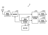
- FIG. 3 is a diagram showing the functional configuration of the wireless receiving device 3 according to the first embodiment.
- the wireless receiving device 3 is an example of a communication device having a function of receiving a wireless signal transmitted by the wireless transmitting device 1, converting the received wireless signal into a wired signal, and transmitting the wired signal.
- the wireless receiving device 3 has a receiving antenna unit 300, a wireless receiving unit 301, a demodulation unit 302, a wireless control signal processing unit 303, a wired signal generating unit 304, wired transmitting units 305A and 305B, and a display unit 306.
- the wireless receiving unit 301 receives the wireless signal emitted into the air as radio waves by the wireless transmitting device 1 using the receiving antenna unit 300, and outputs the received signal to the demodulating unit 302.
- the demodulation unit 302 performs demodulation processing on the received signal corresponding to the modulation method used on the transmitting side, and outputs the bit string of the demodulation result to each of the wired signal generation unit 304 and the wireless control signal processing unit 303. If the modulation method is fixed, the demodulation unit 302 performs demodulation processing using the fixed demodulation method, thereby being able to correctly demodulate the data contained in the received signal.
- the demodulation unit 302 performs demodulation processing corresponding to a predetermined modulation method on the wireless control signal, decodes the modulation method for the signal sequence included in the wired frame, and performs demodulation processing corresponding to the decoded modulation method. It is also possible to limit the candidates for modulation methods for the wireless control signal to about two types. In this case, the demodulation unit 302 may perform demodulation processing corresponding to each of the predetermined modulation method candidates, for example, and attempt to decode each demodulation result, and adopt the demodulation result whose header can be read.
- the wireless control signal processing unit 303 can perform processing based on the wireless control signal. For example, when the wireless control signal includes a known pilot signal, the wireless control signal processing unit 303 can measure communication quality using the received pilot signal. In addition, in a BPSK modulation system, when the wireless control signal includes a known sequence for channel estimation, the wireless control signal processing unit 303 can realize a synchronous detection function including phase tracking such as a PLL (Phase Locked Loop) by observing the phase rotation amount of the known sequence and applying feedback to the down converter of the demodulation unit 302. In addition, the wireless control signal processing unit 303 can measure the SNR using a known signal included in the wireless control signal and treat the SNR as an indicator of communication quality.
- phase tracking such as a PLL (Phase Locked Loop)
- the wireless control signal processing unit 303 can also perform error detection from the demodulation result of the known signal included in the wireless control signal and treat the error detection result as an indicator of communication quality. For example, when the wireless control signal processing unit 303 determines that reception of multiple frames has failed consecutively, it can display communication error information using the display unit 306.
- the display unit 306 may be a display device such as an LED (Light Emitting Diode), or may be an interface that outputs information to an external device such as a serial console.
- the display unit 306 may display not only the wireless control signal but also the FCS result of the wired frame. In this case, the wireless control signal processing unit 303 reads the wired frame from the data obtained from the demodulation unit 302 and executes the FCS.
- the wired signal generating unit 304 extracts the original wired frame, with the wireless control signal removed, from the received signal, and generates a wired signal that is a signal to be transmitted by wire.
- the wired signal generating unit 304 outputs the generated wired signal to either the wired transmitting unit 305A or 305B.
- the wired transmitting unit 305A which is the output destination of the wired signal generating unit 304, corresponds to the wired receiving unit 101A of the wireless transmitting device 1, and the wired transmitting unit 305B corresponds to the wired receiving unit 101B of the wireless transmitting device 1.
- the wired transmitting unit 305A corresponds to the signal system #A
- the wired transmitting unit 305B corresponds to the signal system #B.
- the wired receiving unit 101A and the wired transmitting unit 305A are directly connected, and the wired receiving unit 101B and the wired transmitting unit 305B can be treated as if they were directly connected, without being aware of the presence of a wireless transmission path in between.
- the wired signal generating unit 304 can select the output destination of the received signal from the wired transmitting unit 305A, 305B based on, for example, address information included in the Ethernet frame.
- the wireless control signal processing unit 303 outputs information that allows the wired signal generating unit 304 to determine the output destination of each signal sequence, so that the wired signal generating unit 304 can select the output destination of the generated wired signal. Note that if the preamble of the original wired signal is overwritten when the wireless control signal is inserted, the wired signal generating unit 304 can restore the original wired signal by re-assigning the preamble, which is a predetermined sequence, based on the position of the SFD.
- the wireless transmitting device 1 shown in FIG. 1 and the wireless receiving device 3 shown in FIG. 3 are shown in a case where the number of signal systems transmitted via wired communication is two, but the number of signal systems may be one, or three or more.
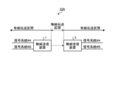
- FIG. 4 is a diagram showing an example of the configuration of a communication system 10A including a wireless transmitting device 1 and a wireless receiving device 3.
- the communication system 10A includes one wireless transmitting device 1 and one wireless receiving device 3 that receives a wireless signal transmitted by the wireless transmitting device 1.
- the wireless transmitting device 1 converts a wired signal into a wireless signal and transmits the wireless signal wirelessly, and the wireless receiving device 3 receives the wireless signal, converts it into a wired signal, and transmits it via wire.
- the wireless transmitting device 1 inserts a wireless control signal, which is a control signal for wireless use, into a section in which no information transmission is performed between multiple frames included in the wired signal, so that it becomes possible to transmit wireless control information for performing various controls in the wireless transmission section to the wireless receiving device 3.
- the wireless receiving device 3 removes the wireless control signal from the received signal and restores the original wired signal, that is, the wired signal received by the wireless transmitting device 1, and transmits it via wire.
- the wired transmission section multiple devices are connected, including the source device and destination device of the wired signal of each signal system.
- the wired signal transmitted in the wired transmission section does not change before and after the wireless transmission section, so each device connected to the wired transmission section can operate without being aware of the existence of the wireless transmission section, that is, in the wireless transmission section, in the same way as if it were connected by wire instead of wirelessly.
- the wireless transmission device 1 is characterized by including wired receiving units 101A and 101B for receiving a wired signal that is a signal transmitted by wire and is composed of a plurality of frames, a wireless control signal providing unit 103 for inserting a wireless control signal, which is a control signal for wireless communication management, into a section where no information transmission is performed between frames of the received wired signal, and a wireless signal generating unit 104 for generating a wireless signal to be transmitted wirelessly using a received bit pattern of the wired signal and the wireless control signal.
- wired receiving units 101A and 101B for receiving a wired signal that is a signal transmitted by wire and is composed of a plurality of frames
- a wireless control signal providing unit 103 for inserting a wireless control signal, which is a control signal for wireless communication management, into a section where no information transmission is performed between frames of the received wired signal
- a wireless signal generating unit 104 for generating a wireless signal to be transmitted wirelessly using a received bit pattern of the wired signal and the wireless
- the wireless transmission device 1 when it receives a wired signal, it transmits a wireless signal in which a wireless control signal, which is a control signal for wireless communication management, is inserted into a section where no information transmission is performed between frames of the wired signal, so that in a wireless transmission section where part of the wired communication is wireless, it is possible to perform wireless communication management of the wireless transmission section using the wireless control signal.
- Wireless communication management refers to grasping the communication environment, such as the communication quality of the wireless transmission section, and adjusting parameters related to wireless communication, such as the communication rate. This makes it possible to externally monitor the wireless communication environment, isolate the cause of communication problems, and check the communication status when a communication failure occurs. It also provides a means to select the wireless transmission mode according to the communication quality, making it possible to flexibly provide various communication functions such as adjusting the transmission rate and signal multiplexing.
- the wireless signal generating unit 104 can generate a wireless signal including a wireless control signal that is longer than the section in which no information is transmitted between frames of the wired signal by overwriting the preamble included in the frame with the wireless control signal.
- the wireless transmission device 1 does not need to perform error detection processing even if the wired signal includes an error detection code. This makes it possible to suppress the occurrence of delay jitter and to easily achieve low delay, low delay fluctuation, and communication quality.
- the wireless transmission device 1 also includes multiple wired receiving units 101A, 101B corresponding to the multiple signal systems, and one wireless transmission unit 105 that transmits wireless signals.
- the wireless signal generation unit 104 multiplexes the multiple signal systems to generate a wireless signal, and the single wireless transmission unit 105 can multiplex and transmit the multiple signal systems.
- a wired connection requires one wire for each signal system
- the wireless transmission device 1 makes it possible to transmit and receive multiple signal systems with a single antenna. In this case, by using a channel that controls interference between the signal systems, the effects of interference can be suppressed and communication quality can be maintained, even when multiple signal systems are transmitted and received simultaneously with a single antenna.
- the frames that make up the wired signal may be Ethernet frames.
- the wireless receiving device 3 that receives the wireless signal transmitted by the wireless transmitting device 1 can include a wireless control signal processing unit 303 that performs wireless communication management in the wireless transmission section by the wireless signal based on the wireless control signal included in the wireless signal.
- a wireless control signal processing unit 303 that performs wireless communication management in the wireless transmission section by the wireless signal based on the wireless control signal included in the wireless signal.
- the wireless control signal processing unit 303 can perform at least one of measuring the wireless communication quality in the wireless transmission section and controlling the operation of the reception processing of the wireless signal transmitted by the wireless transmitting device 1 as wireless communication management.
- the wireless receiving device 3 can further include a wired signal generating unit 304 that removes the wireless control signal from the received wireless signal to restore the wired signal received by the wireless transmitting device 1, and wired transmitting units 305A, 305B that transmit the restored wired signal via a wired connection.
- a wired signal generating unit 304 that removes the wireless control signal from the received wireless signal to restore the wired signal received by the wireless transmitting device 1, and wired transmitting units 305A, 305B that transmit the restored wired signal via a wired connection.
- the preamble portion of the frame may be overwritten.
- the wired signal generating unit 304 of the wireless receiving device 3 cannot detect a preamble of a predetermined bit pattern in the frame portion for transmitting information of the received wireless signal, the wired signal is restored by re-adding the preamble. Therefore, even if the preamble portion of the frame is overwritten by a wireless control signal in the wireless transmitting device 1, it is possible to reliably restore the original wired signal.
- the functions of the wireless transmission device 1 according to the first embodiment can be realized using a control circuit, as described below.
- This control circuit controls the wireless transmission device 1, which receives a wired signal that is a signal transmitted by wire and is composed of a plurality of frames, converts the wired signal into a wireless signal, and transmits it, and can cause the wireless transmission device 1 to execute a step of inserting a wireless control signal, which is a control signal for managing wireless communication, into a section in which no information transmission is taking place between frames of the received wired signal.
- This storage medium stores a program for controlling the wireless transmission device 1, which receives a wired signal that is a signal transmitted by wire and is composed of a plurality of frames, converts the wired signal into a wireless signal, and transmits the signal.
- the program can cause the wireless transmission device 1 to execute a step of inserting a wireless control signal, which is a control signal for wireless communication, into a section between frames of the received wired signal where no information transmission is taking place.
- the communication system 10A also includes a wireless transmitting device 1 that converts part of the wired communication into a wireless signal, receives a wired signal that is a signal transmitted by wire and is composed of a plurality of frames, generates a wireless signal by inserting a wireless control signal, which is a control signal for wireless communication, into a section where no information transmission occurs between the frames of the received wired signal, and transmits the generated wireless signal; and a wireless receiving device 3 that receives the wireless signal transmitted by the wireless transmitting device 1, performs wireless communication management in the wireless transmission section by the wireless signal based on the wireless control signal contained in the received wireless signal, removes the wireless control signal from the received wireless signal, restores the wired signal received by the wireless transmitting device 1, and transmits the restored wired signal via a wired connection.
- a wireless transmitting device 1 that converts part of the wired communication into a wireless signal, receives a wired signal that is a signal transmitted by wire and is composed of a plurality of frames, generates a wireless signal by
- a communication method for making part of wired communication wireless includes the steps of: a wireless transmitting device 1 receiving a wired signal that is a signal transmitted by wire and is composed of a plurality of frames; a wireless transmitting device 1 generating a wireless signal by inserting a wireless control signal, which is a control signal for wireless communication, into a section where no information transmission is performed between frames of the received wired signal; a wireless transmitting device 1 transmitting the generated wireless signal; a wireless receiving device 3 receiving the wireless signal; a wireless receiving device 3 performing wireless communication management in the wireless transmission section by the wireless signal based on the wireless control signal included in the received wireless signal; a wireless receiving device 3 removing the wireless control signal from the received wireless signal to restore the wired signal received by the wireless transmitting device 1; and a wireless receiving device 3 transmitting the restored wired signal by wire.
- Embodiment 2 the wireless signal transmitted by the wireless transmitting device 1 is directly transmitted to the wireless receiving device 3 , but the wireless signal may be transmitted via the wireless relay device 4 .
- FIG. 5 is a diagram showing an example of the configuration of a communication system 10B including a wireless transmitting device 1, a wireless receiving device 3, and a wireless relay device 4. Note that, although the configuration of the communication system 10B including one wireless relay device 4 is shown here, the configuration may also be such that a wireless signal transmitted by the wireless transmitting device 1 is relayed in series by two wireless relay devices 4 and transmitted to the wireless receiving device 3.
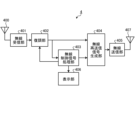
- FIG. 6 is a diagram showing the functional configuration of the wireless relay device 4 according to the second embodiment.
- the wireless relay device 4 has a receiving antenna unit 400, a wireless receiving unit 401, a demodulation unit 402, a wireless control signal processing unit 403, a wireless retransmission signal generating unit 404, a wireless transmitting unit 405, a display unit 406, and a transmitting antenna unit 407.
- the receiving antenna unit 400 has the same function as the receiving antenna unit 300.
- the wireless receiving unit 401 has the same function as the wireless receiving unit 301.
- the demodulation unit 402 has the same function as the demodulation unit 302.
- the display unit 406 has the same function as the display unit 306.
- the wireless control signal processing unit 403 has a function of generating a wireless control signal for a signal to be transmitted as a relay signal in the same manner as the wireless control signal providing unit 103, and outputting the generated wireless control signal as a bit string to the wireless retransmission signal generating unit 404.
- the wireless control signal generated by the wireless control signal processing unit 403 may be the same as the received wireless control signal, or may be, for example, the received wireless control signal plus information such as the number of relays indicating how many hops the signal will be relayed through.
- a different control signal from the previous link may be sent by selecting a different sequence as a pilot signal that has good orthogonality to the signal of the previous link.
- the wireless retransmission signal generating unit 404 generates a wireless retransmission signal, which is a signal to be retransmitted as a relay signal, based on the received bit pattern of the wireless signal output by the demodulating unit 402 and the bit sequence of the wireless control signal output by the wireless control signal processing unit 403, and outputs the generated wireless retransmission signal to the wireless transmitting unit 405.
- the wireless transmission unit 405 has the same function as the wireless transmission unit 105, and transmits the wireless retransmission signal output by the wireless retransmission signal generation unit 404 using the transmission antenna unit 407.
- the transmission antenna unit 407 has the same function as the transmission antenna unit 106.
- the wireless relay device 4 shown in FIG. 6 has both a function for receiving wireless signals and a function for transmitting wireless signals, all of the functions of the wireless relay device 4 do not have to be housed in a single housing and realized as a single device.
- the demodulation function on the receiving side and the signal generation function on the transmitting side may be implemented in physically separate locations.
- the demodulation unit 402 and the wireless retransmission signal generation unit 404 may be connected by a cable of about several meters. Note that not only between the demodulation unit 402 and the wireless retransmission signal generation unit 404, but also between any other components, the connection may be made by a cable of about several meters. This provides the effect of making it easier to ensure communication performance by combining a wired connection, which is more resistant to electromagnetic noise than wireless.
- the wireless relay device 4 is a wireless relay device 4 that relays a wireless signal transmitted by the wireless transmission device 1, and can include a wireless retransmission signal generation unit 404 that generates a wireless retransmission signal, which is a wireless signal to be retransmitted, based on the received wireless signal, and a wireless transmission unit 405 that transmits the wireless retransmission signal.
- a wireless retransmission signal generation unit 404 that generates a wireless retransmission signal, which is a wireless signal to be retransmitted, based on the received wireless signal
- a wireless transmission unit 405 that transmits the wireless retransmission signal.
- the wireless relay device 4 further includes a wireless control signal processing unit 403 that adds information about the number of relays to the wireless control signal included in the received wireless signal to generate a wireless control signal for a wireless retransmission signal, and the wireless retransmission signal generating unit 404 generates a wireless retransmission signal that includes the wireless control signal generated by the wireless control signal processing unit 403.
- the wireless relay device 4 By using the wireless relay device 4, it becomes possible to extend the wireless transmission distance of a wireless signal that is generated by converting a wired signal and has a wireless control signal inserted therein.
- the wireless transmitting device 1 having the function of transmitting wireless signals and the wireless receiving device 3 having the function of receiving wireless signals are separate devices, but a single communication device 6 may have both the functions of the wireless transmitting device 1 and the wireless receiving device 3.
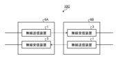
- FIG. 7 is a diagram showing an example configuration of a communication system 10C including communication devices 6A and 6B with two-way communication capabilities. Note that here, the two communication devices 6 with two-way communication capabilities are distinguished by being referred to as communication devices 6A and 6B.
- Communication system 10C includes communication device 6A and communication device 6B.
- Each of the communication devices 6A and 6B has a wireless transmitting device 1 and a wireless receiving device 3.
- the function of the wireless transmitting device 1 is the same as that described with reference to FIG. 1, and therefore a description thereof will be omitted here.
- the function of the wireless receiving device 3 is the same as that described with reference to FIG. 3, and therefore a description thereof will be omitted here.
- the wireless receiving device 3 of the communication device 6B receives the wireless signal that the wireless transmitting device 1 of the communication device 6A converts a wired signal into a wireless signal and transmits wirelessly.
- the wireless receiving device 3 of the communication device 6B can perform various wireless control processing based on the demodulation result of the wireless control signal included in the received wireless signal.
- the wireless receiving device 3 of the communication device 6A receives the wireless signal that the wireless transmitting device 1 of the communication device 6B converts a wired signal into a wireless signal and transmits wirelessly.
- the wireless receiving device 3 of the communication device 6A can also perform various wireless control processing based on the demodulation result of the wireless control signal included in the received wireless signal. In this way, by using communication devices 6A and 6B equipped with wireless transmitting device 1 and wireless receiving device 3, it is possible to wirelessly communicate in both directions between two points that are part of a wired system. Since wireless control signals are included in the wireless signals between communication devices 6A and 6B, it is possible to realize various wireless control processes even when part of the wired communication is wireless.
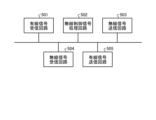
- FIG. 8 is a diagram showing an example of the hardware configuration.
- the communication device 6 performs bidirectional communication using FDD (Frequency Division Duplex) or TDD (Time Division Duplex), and has the functions of both a wireless transmitting device 1 and a wireless receiving device 3.
- FDD Frequency Division Duplex
- TDD Time Division Duplex
- the communication device 6 has a wired signal receiving circuit 501, a wireless control signal processing circuit 502, a wireless signal transmitting circuit 503, a wireless signal receiving circuit 504, and a wired signal transmitting circuit 505.
- the wired signal receiving circuit 501 has a function of receiving a wired signal and generating demodulated data.
- the wireless control signal processing circuit 502 has a function of providing a wireless control signal, processing the wireless control signal, and displaying the communication quality.
- the wireless signal transmitting circuit 503 has a function of generating and modulating a wireless signal, and converting it to a wireless frequency.
- the wireless signal receiving circuit 504 has a function of converting a wireless signal from a wireless frequency to a baseband or intermediate frequency, and performing demodulation processing.
- the wired signal transmitting circuit 505 has a function of generating a wired signal and transmitting the generated wired signal.
- the functions of the wired receivers 101A, 101B and the wired signal detector 102 are realized by the wired signal receiver circuit 501.
- the function of the wireless control signal provider 103 is realized by the wireless control signal processor circuit 502.
- the functions of the wireless signal generator 104 and the wireless transmitter 105 are realized by the wireless signal transmitter circuit 503.
- the functions of the wireless transmitter 1 can be realized by the wired signal receiver circuit 501, the wireless control signal processor circuit 502, and the wireless signal transmitter circuit 503.
- the functions of the wireless receiving unit 301 and the demodulating unit 302 are realized by the wireless signal receiving circuit 504.
- the functions of the wireless control signal processing unit 303 and the display unit 306 are realized by the wireless control signal processing circuit 502.
- the functions of the wired signal generating unit 304 and the wired transmitting units 305A and 305B are realized by the wired signal transmitting circuit 505.
- the functions of the wireless receiving device 3 can be realized by the wireless signal receiving circuit 504, the wireless control signal processing circuit 502, and the wired signal transmitting circuit 505.
- the functions of the wireless receiver 401 and demodulator 402 are realized by the wireless signal receiver circuit 504.
- the functions of the wireless control signal processor 403 and display 406 are realized by the wireless control signal processor circuit 502.
- the functions of the wireless retransmission signal generator 404 and wireless transmitter 405 are realized by the wireless signal transmitter circuit 503.
- the functions of the wireless relay device 4 can be realized by the wireless signal receiver circuit 504, the wireless control signal processor circuit 502, and the wireless signal transmitter circuit 503.
- each of the wired signal receiving circuit 501, the wireless control signal processing circuit 502, the wireless signal transmitting circuit 503, the wireless signal receiving circuit 504, and the wired signal transmitting circuit 505 is a processing circuit.
- These processing circuits may be dedicated hardware or a control circuit using a CPU (Central Processing Unit).
- the processing circuit is a single circuit, a composite circuit, a programmed processor, a parallel programmed processor, an ASIC (Application Specific Integrated Circuit), an FPGA (Field Programmable Gate Array), or a combination of these.
- the processing circuit has a CPU and a memory, and the CPU can realize the processing of each component by reading and executing a program stored in the memory.
- the CPU is also called an arithmetic unit, a microprocessor, a microcomputer, a DSP (Digital Signal Processor), etc.
- Examples of memory include non-volatile or volatile semiconductor memory such as RAM (Random Access Memory), ROM (Read Only Memory), flash memory, EPROM (Erasable Programmable ROM), EEPROM (Electrically EPROM), magnetic disks, flexible disks, optical disks, compact disks, mini disks, and DVDs (Digital Versatile Disks).
- Memory is also used as temporary memory for each process executed by the CPU.
- the programs executed by the CPU may be provided in a state stored in a storage medium, or may be provided via a network such as the Internet.
Landscapes
- Engineering & Computer Science (AREA)
- Computer Networks & Wireless Communication (AREA)
- Signal Processing (AREA)
- Quality & Reliability (AREA)
- Physics & Mathematics (AREA)
- Electromagnetism (AREA)
- Power Engineering (AREA)
- Computer Security & Cryptography (AREA)
- Mobile Radio Communication Systems (AREA)
Abstract
Description
図1は、実施の形態1にかかる無線送信装置1の機能構成を示す図である。無線送信装置1は、有線で伝送される信号である有線信号を受信する機能と、有線信号を無線信号に変換して無線送信する機能とを有する通信装置の一例である。
図4では、無線送信装置1が送信した無線信号は、無線受信装置3に直接伝送されることとしたが、無線信号は無線中継装置4を介して伝送されてもよい。
Claims (15)
- 有線で伝送される信号であって複数のフレームから構成される有線信号を受信する有線受信部と、
受信した前記有線信号のフレーム間の情報伝送を行っていない区間に、無線通信管理用の制御信号である無線制御信号を挿入する無線制御信号付与部と、
前記有線信号の受信ビットパターンと前記無線制御信号とを用いて、無線送信する無線信号を生成する無線信号生成部と、
を備えることを特徴とする無線送信装置。 - 前記無線信号生成部は、前記フレームに含まれるプリアンブルを前記無線制御信号で上書きすることによって、前記有線信号のフレーム間の情報伝送を行っていない前記区間よりも長い前記無線制御信号を含む前記無線信号を生成することを特徴とする請求項1に記載の無線送信装置。
- 前記有線信号が誤り検出符号を含む場合であっても、誤り検出処理を実行しないことを特徴とする請求項1または2に記載の無線送信装置。
- 複数の信号系統のそれぞれに対応する複数の前記有線受信部と、
前記無線信号を送信する1つの無線送信部と、
を備え、
前記無線信号生成部は、複数の前記信号系統を多重して前記無線信号を生成し、
1つの前記無線送信部で複数の前記信号系統を多重伝送することを特徴とする請求項1から3のいずれか1項に記載の無線送信装置。 - 前記有線信号を構成する前記フレームは、イーサネットフレームであることを特徴とする請求項1から4のいずれか1項に記載の無線送信装置。
- 請求項1から5のいずれか1項に記載の無線送信装置が送信した前記無線信号を受信する無線受信装置であって、
前記無線信号に含まれる前記無線制御信号に基づいて、前記無線信号による無線伝送区間における無線通信管理を行う無線制御信号処理部と、
を備えることを特徴とする無線受信装置。 - 前記無線制御信号処理部は、前記無線通信管理として、前記無線伝送区間における無線通信品質の測定と、前記無線送信装置が送信した前記無線信号の受信処理の動作制御とのうち少なくとも一方を行うことを特徴とする請求項6に記載の無線受信装置。
- 受信した前記無線信号から前記無線制御信号を取り除いて前記無線送信装置が受信した前記有線信号を復元する有線信号生成部と、
復元した前記有線信号を有線送信する有線送信部と、
をさらに備えることを特徴とする請求項6に記載の無線受信装置。 - 前記有線信号生成部は、受信した前記無線信号の情報伝送用のフレーム部分に予め定められたプリアンブルが検出できない場合、前記プリアンブルを再付与することによって前記有線信号を復元することを特徴とする請求項8に記載の無線受信装置。
- 請求項1から5のいずれか1項に記載の無線送信装置が送信した前記無線信号を中継する無線中継装置であって、
受信した前記無線信号に基づいて、再送信する無線信号である無線再送信信号を生成する無線再送信信号生成部と、
前記無線再送信信号を送信する無線送信部と、
を備えることを特徴とする無線中継装置。 - 受信した前記無線信号に含まれる前記無線制御信号に、中継回数の情報を加えて前記無線再送信信号の無線制御信号を生成する無線制御信号処理部、
をさらに備え、
前記無線再送信信号生成部は、前記無線制御信号処理部が生成する前記無線制御信号を含む前記無線再送信信号を生成することを特徴とする請求項10に記載の無線中継装置。 - 有線で伝送される信号であって複数のフレームから構成される有線信号を受信し、前記有線信号を無線信号に変換して送信する無線送信装置を制御する制御回路であって、
受信した前記有線信号のフレーム間の情報伝送を行っていない区間に、無線通信管理用の制御信号である無線制御信号を挿入するステップ、
を前記無線送信装置に実行させることを特徴とする制御回路。 - 有線で伝送される信号であって複数のフレームから構成される有線信号を受信し、前記有線信号を無線信号に変換して送信する無線送信装置を制御するためのプログラムを記憶した記憶媒体において、該プログラムは、
受信した前記有線信号のフレーム間の情報伝送を行っていない区間に、無線通信用の制御信号である無線制御信号を挿入するステップ、
を前記無線送信装置に実行させることを特徴とする記憶媒体。 - 有線通信の一部を無線化する通信システムであって、
有線で伝送される信号であって複数のフレームから構成される有線信号を受信し、受信した前記有線信号のフレーム間の情報伝送を行っていない区間に、無線通信用の制御信号である無線制御信号を挿入した無線信号を生成し、生成した前記無線信号を送信する無線送信装置と、
前記無線送信装置が送信する前記無線信号を受信し、受信した前記無線信号に含まれる前記無線制御信号に基づいて、前記無線信号による無線伝送区間における無線通信管理を行うと共に、受信した前記無線信号から前記無線制御信号を取り除いて、前記無線送信装置が受信した前記有線信号を復元し、復元した前記有線信号を有線送信する無線受信装置と、
を備えることを特徴とする通信システム。 - 有線通信の一部を無線化する通信方法であって、
無線送信装置が、有線で伝送される信号であって複数のフレームから構成される有線信号を受信するステップと、
前記無線送信装置が、受信した前記有線信号のフレーム間の情報伝送を行っていない区間に、無線通信用の制御信号である無線制御信号を挿入した無線信号を生成するステップと、
前記無線送信装置が、生成した前記無線信号を送信するステップと、
無線受信装置が、前記無線信号を受信するステップと、
前記無線受信装置が、受信した前記無線信号に含まれる前記無線制御信号に基づいて、前記無線信号による無線伝送区間における無線通信管理を行うステップと、
前記無線受信装置が、受信した前記無線信号から前記無線制御信号を取り除いて、前記無線送信装置が受信した前記有線信号を復元するステップと、
前記無線受信装置が、復元した前記有線信号を有線送信するステップと、
を含むことを特徴とする通信方法。
Priority Applications (7)
| Application Number | Priority Date | Filing Date | Title |
|---|---|---|---|
| CN202380099224.XA CN121312188A (zh) | 2023-06-13 | 2023-06-13 | 无线发送装置、无线接收装置、无线中继装置、控制电路、存储介质、通信系统及通信方法 |
| DE112023006150.5T DE112023006150T5 (de) | 2023-06-13 | 2023-06-13 | Drahtlos-Übertrager, Drahtlos-Empfänger, Drahtlos-Relais, Steuerschaltung, Speichermedium, Kommunikationssystem und Kommunikationsverfahren |
| KR1020257040194A KR20250177400A (ko) | 2023-06-13 | 2023-06-13 | 무선 송신 장치, 무선 수신 장치, 무선 중계 장치, 제어 회로, 기억 매체, 통신 시스템, 및 통신 방법 |
| PCT/JP2023/021912 WO2024257217A1 (ja) | 2023-06-13 | 2023-06-13 | 無線送信装置、無線受信装置、無線中継装置、制御回路、記憶媒体、通信システムおよび通信方法 |
| JP2023568748A JP7471539B1 (ja) | 2023-06-13 | 2023-06-13 | 無線送信装置、無線受信装置、無線中継装置、制御回路、記憶媒体、通信システムおよび通信方法 |
| TW112147403A TW202502000A (zh) | 2023-06-13 | 2023-12-06 | 無線傳送裝置、無線接收裝置、無線中繼裝置、控制電路、記憶媒體、通訊系統及通訊方法 |
| US19/386,667 US20260067750A1 (en) | 2023-06-13 | 2025-11-12 | Wireless transmitter, wireless receiver, wireless relay, control circuit, storage medium, communication system, and communication method |
Applications Claiming Priority (1)
| Application Number | Priority Date | Filing Date | Title |
|---|---|---|---|
| PCT/JP2023/021912 WO2024257217A1 (ja) | 2023-06-13 | 2023-06-13 | 無線送信装置、無線受信装置、無線中継装置、制御回路、記憶媒体、通信システムおよび通信方法 |
Related Child Applications (1)
| Application Number | Title | Priority Date | Filing Date |
|---|---|---|---|
| US19/386,667 Continuation US20260067750A1 (en) | 2023-06-13 | 2025-11-12 | Wireless transmitter, wireless receiver, wireless relay, control circuit, storage medium, communication system, and communication method |
Publications (1)
| Publication Number | Publication Date |
|---|---|
| WO2024257217A1 true WO2024257217A1 (ja) | 2024-12-19 |
Family
ID=90716069
Family Applications (1)
| Application Number | Title | Priority Date | Filing Date |
|---|---|---|---|
| PCT/JP2023/021912 Ceased WO2024257217A1 (ja) | 2023-06-13 | 2023-06-13 | 無線送信装置、無線受信装置、無線中継装置、制御回路、記憶媒体、通信システムおよび通信方法 |
Country Status (7)
| Country | Link |
|---|---|
| US (1) | US20260067750A1 (ja) |
| JP (1) | JP7471539B1 (ja) |
| KR (1) | KR20250177400A (ja) |
| CN (1) | CN121312188A (ja) |
| DE (1) | DE112023006150T5 (ja) |
| TW (1) | TW202502000A (ja) |
| WO (1) | WO2024257217A1 (ja) |
Citations (4)
| Publication number | Priority date | Publication date | Assignee | Title |
|---|---|---|---|---|
| JP2001197074A (ja) * | 2000-01-13 | 2001-07-19 | Root Inc | データ送受信装置を利用したローカルエリアネットワーク、および、ローカルエリアネットワークに利用される中継装置 |
| JP2005198019A (ja) * | 2004-01-07 | 2005-07-21 | Hitachi Cable Ltd | 無線端末 |
| US20130170375A1 (en) * | 2011-12-30 | 2013-07-04 | Electronics And Telecommunications Research Institute | Wired/wireless converged mac adaptor and method of transmitting frame using wired/wireless converged mac adaptor |
| JP2017112395A (ja) * | 2014-03-17 | 2017-06-22 | 日本電気株式会社 | 無線通信装置、無線通信システム、自動設定方法及びプログラム |
Family Cites Families (2)
| Publication number | Priority date | Publication date | Assignee | Title |
|---|---|---|---|---|
| JP4199639B2 (ja) * | 2003-10-28 | 2008-12-17 | 株式会社日立国際電気 | フレームフォーマット変換方式 |
| DE102016213076A1 (de) | 2016-07-18 | 2018-01-18 | Te Connectivity Germany Gmbh | Kontaktloser übertragungskoppler für datennetze |
-
2023
- 2023-06-13 DE DE112023006150.5T patent/DE112023006150T5/de active Pending
- 2023-06-13 CN CN202380099224.XA patent/CN121312188A/zh active Pending
- 2023-06-13 WO PCT/JP2023/021912 patent/WO2024257217A1/ja not_active Ceased
- 2023-06-13 JP JP2023568748A patent/JP7471539B1/ja active Active
- 2023-06-13 KR KR1020257040194A patent/KR20250177400A/ko active Pending
- 2023-12-06 TW TW112147403A patent/TW202502000A/zh unknown
-
2025
- 2025-11-12 US US19/386,667 patent/US20260067750A1/en active Pending
Patent Citations (4)
| Publication number | Priority date | Publication date | Assignee | Title |
|---|---|---|---|---|
| JP2001197074A (ja) * | 2000-01-13 | 2001-07-19 | Root Inc | データ送受信装置を利用したローカルエリアネットワーク、および、ローカルエリアネットワークに利用される中継装置 |
| JP2005198019A (ja) * | 2004-01-07 | 2005-07-21 | Hitachi Cable Ltd | 無線端末 |
| US20130170375A1 (en) * | 2011-12-30 | 2013-07-04 | Electronics And Telecommunications Research Institute | Wired/wireless converged mac adaptor and method of transmitting frame using wired/wireless converged mac adaptor |
| JP2017112395A (ja) * | 2014-03-17 | 2017-06-22 | 日本電気株式会社 | 無線通信装置、無線通信システム、自動設定方法及びプログラム |
Also Published As
| Publication number | Publication date |
|---|---|
| CN121312188A (zh) | 2026-01-09 |
| US20260067750A1 (en) | 2026-03-05 |
| DE112023006150T5 (de) | 2026-03-05 |
| TW202502000A (zh) | 2025-01-01 |
| JPWO2024257217A1 (ja) | 2024-12-19 |
| KR20250177400A (ko) | 2025-12-23 |
| JP7471539B1 (ja) | 2024-04-19 |
Similar Documents
| Publication | Publication Date | Title |
|---|---|---|
| US12457040B2 (en) | Optical transmission system and transmission mode selecting method | |
| US8660425B2 (en) | Optical transmitting device and optical receiving device | |
| JP5355078B2 (ja) | 送信装置、受信装置及び通信方法 | |
| EP1735935B1 (en) | Wireless audio transmission system and method with dynamic slot allocation | |
| US6990059B1 (en) | Interference mitigation in a wireless communication system | |
| US8750266B2 (en) | Dual transmission for communication networks | |
| US7855948B2 (en) | Interference mitigation in a wireless communication system | |
| US8401038B2 (en) | False lock detection for physical layer frame synchronization | |
| US20080170540A1 (en) | Communication system, communication device, and communication method | |
| US7826340B2 (en) | Hierarchical modulation reverse link interface node providing multiple service levels | |
| KR20040092826A (ko) | 이동통신 시스템에서의 신호전송 방법 및 장치 | |
| RU2369019C2 (ru) | Эффективное обнаружение фактов ошибочной интерпретации сообщений о подтверждении приема (аск) как сообщений о неподтверждении приема (nack) | |
| KR20010049892A (ko) | 무선 시스템용 데이터 링크 프로토콜 | |
| US7613977B2 (en) | Retransmission control method and transmitter in wireless communication system | |
| JP2008193305A (ja) | 通信システム並びに通信装置 | |
| JP7471539B1 (ja) | 無線送信装置、無線受信装置、無線中継装置、制御回路、記憶媒体、通信システムおよび通信方法 | |
| US20090052375A1 (en) | Hierarchical modulation reverse link interface node | |
| JP4653680B2 (ja) | データ伝送装置およびデータ伝送システム | |
| KR20040092915A (ko) | 초광대역 통신 시스템에서 채널 상태에 따른 변조 및 코딩방식 제어 장치 및 방법 | |
| Brahma et al. | Quilt: A decode/quantize-interleave-transmit approach to cooperative relaying | |
| Volkhausen et al. | Efficient cooperative relaying in wireless multi-hop networks with commodity WiFi hardware | |
| WO2003017560A1 (en) | Retransmission method and apparatus for wireless communications systems | |
| KR100551858B1 (ko) | 다중 입출력 이동 통신 시스템에서의 데이터 신호송수신방법 | |
| WO2009029600A2 (en) | Hierarchical modulation reverse link interface node | |
| JP2008154297A (ja) | データ伝送装置およびデータ伝送システム |
Legal Events
| Date | Code | Title | Description |
|---|---|---|---|
| WWE | Wipo information: entry into national phase |
Ref document number: 2023568748 Country of ref document: JP |
|
| 121 | Ep: the epo has been informed by wipo that ep was designated in this application |
Ref document number: 23941525 Country of ref document: EP Kind code of ref document: A1 |
|
| ENP | Entry into the national phase |
Ref document number: 1020257040194 Country of ref document: KR Free format text: ST27 STATUS EVENT CODE: A-0-1-A10-A15-NAP-PA0105 (AS PROVIDED BY THE NATIONAL OFFICE) |
|
| WWE | Wipo information: entry into national phase |
Ref document number: 1020257040194 Country of ref document: KR |
|
| WWE | Wipo information: entry into national phase |
Ref document number: 112023006150 Country of ref document: DE |
|
| WWP | Wipo information: published in national office |
Ref document number: 1020257040194 Country of ref document: KR |
|
| WWP | Wipo information: published in national office |
Ref document number: 112023006150 Country of ref document: DE |