WO2024253206A1 - 空気清浄機及びその制御方法 - Google Patents
空気清浄機及びその制御方法 Download PDFInfo
- Publication number
- WO2024253206A1 WO2024253206A1 PCT/JP2024/020949 JP2024020949W WO2024253206A1 WO 2024253206 A1 WO2024253206 A1 WO 2024253206A1 JP 2024020949 W JP2024020949 W JP 2024020949W WO 2024253206 A1 WO2024253206 A1 WO 2024253206A1
- Authority
- WO
- WIPO (PCT)
- Prior art keywords
- detection unit
- air
- gas passage
- inner case
- air quality
- Prior art date
- Legal status (The legal status is an assumption and is not a legal conclusion. Google has not performed a legal analysis and makes no representation as to the accuracy of the status listed.)
- Ceased
Links
Images





Classifications
-
- F—MECHANICAL ENGINEERING; LIGHTING; HEATING; WEAPONS; BLASTING
- F24—HEATING; RANGES; VENTILATING
- F24F—AIR-CONDITIONING; AIR-HUMIDIFICATION; VENTILATION; USE OF AIR CURRENTS FOR SCREENING
- F24F7/00—Ventilation
- F24F7/003—Ventilation in combination with air cleaning
-
- F—MECHANICAL ENGINEERING; LIGHTING; HEATING; WEAPONS; BLASTING
- F24—HEATING; RANGES; VENTILATING
- F24F—AIR-CONDITIONING; AIR-HUMIDIFICATION; VENTILATION; USE OF AIR CURRENTS FOR SCREENING
- F24F11/00—Control or safety arrangements
- F24F11/30—Control or safety arrangements for purposes related to the operation of the system, e.g. for safety or monitoring
-
- F—MECHANICAL ENGINEERING; LIGHTING; HEATING; WEAPONS; BLASTING
- F24—HEATING; RANGES; VENTILATING
- F24F—AIR-CONDITIONING; AIR-HUMIDIFICATION; VENTILATION; USE OF AIR CURRENTS FOR SCREENING
- F24F11/00—Control or safety arrangements
- F24F11/89—Arrangement or mounting of control or safety devices
-
- F—MECHANICAL ENGINEERING; LIGHTING; HEATING; WEAPONS; BLASTING
- F24—HEATING; RANGES; VENTILATING
- F24F—AIR-CONDITIONING; AIR-HUMIDIFICATION; VENTILATION; USE OF AIR CURRENTS FOR SCREENING
- F24F8/00—Treatment, e.g. purification, of air supplied to human living or working spaces otherwise than by heating, cooling, humidifying or drying
- F24F8/80—Self-contained air purifiers
-
- F—MECHANICAL ENGINEERING; LIGHTING; HEATING; WEAPONS; BLASTING
- F24—HEATING; RANGES; VENTILATING
- F24F—AIR-CONDITIONING; AIR-HUMIDIFICATION; VENTILATION; USE OF AIR CURRENTS FOR SCREENING
- F24F2110/00—Control inputs relating to air properties
- F24F2110/30—Velocity
Definitions
- This application relates to the field of air purification, and in particular to an air purifier and a control method thereof.
- the main way to improve the air quality within a space is to purify the air within the space using air purification equipment.
- the air to be purified is drawn into the equipment, where it is purified using adsorption technology, negative (positive) ion technology, catalyst technology, photocatalysis technology, ultra-structured photomineralization technology, HEPA high-efficiency filtration technology, electrostatic precipitator technology, etc., and then discharged outside the equipment.
- the air quality within a space is not only related to the air quality outside the space, but also to human activity within the space.
- pollutants such as harmful gases volatilizing from interior materials, oily smoke from cooking, and blanket-like fibers from textiles all affect the air quality inside the room.
- pollutants such as harmful gases volatilizing from decorative materials and exhaust gases recirculating inside the car also affect the air quality inside the car.
- airborne pollutants are usually distributed unevenly in space or time.
- formaldehyde when a decorative material releases harmful gases such as formaldehyde, the formaldehyde concentration will be higher in areas closer to the decorative material, and in terms of time, the concentration of oily smoke during cooking will be higher than the concentration of oily smoke when not cooking.
- air purification equipment in conventional technology cannot intentionally purify situations where such pollutants are distributed unevenly in space or time, and the purification efficiency is low.
- an embodiment of the present application provides an air purifier and a control method thereof.
- an air purifier in a first aspect of the embodiment of the present application, includes a purifier body and a detection unit that is provided in the purifier body and detects air quality in multiple directions in the circumferential direction of the purifier body in a stepwise manner.
- an air purifier control method for controlling the air purifier described in the first aspect of the embodiment of the present application including controlling the detection unit to detect air quality in multiple directions in the circumferential direction of the purifier body in a stepwise manner.
- One of the beneficial effects of the embodiment of the present application is that by using the detection unit to detect the air quality in multiple directions in the circumferential direction of the purifier body in stages, the direction of the cleaning process can be determined based on the detection results in different directions. This allows for highly directional air cleaning process and improves cleaning efficiency.
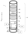
- FIG. 1 is a schematic diagram of an air purifier according to an embodiment of the present application.
- FIG. 1 is a perspective view of an embodiment of an air purifier according to an embodiment of the present application.
- FIG. 3 is a schematic diagram of the air purifier shown in FIG. 2 in an operating state.
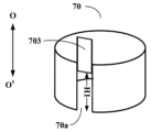
- FIG. 2 is a schematic diagram of an embodiment of an inner case according to an embodiment of the present application.
- FIG. 13 is a schematic diagram of another embodiment of the inner case according to the embodiment of the present application.
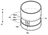
- 13 is a schematic diagram of a further embodiment of an inner case according to an embodiment of the present application.
- 13 is a schematic diagram of a further embodiment of an inner case according to an embodiment of the present application.
- FIG. 2 is a schematic diagram of a control method for an air purifier according to an embodiment of the present application.
- the direction of gravity will be referred to as the "axial direction,” and the direction around the “axial direction” will be referred to as the “circumferential direction.”
- FIG. 1 is a schematic diagram of an air purifier according to an embodiment of the present application.
- the air purifier 1 includes a purifier main body 10 and a detection unit 20 provided in the purifier main body 10.
- the purifier body 10 has a columnar structure and includes an intake port 110 provided on the outer peripheral surface, a filter 120 provided inside, a fan 130, and an exhaust port 140 provided on the upper part.
- the intake port 110, the filter 120, the fan 130, and the exhaust port 140 are provided, for example, along the axial direction OO'.
- the fan 130 operates to suck air around the purifier body 10 from the intake port 110 into the inside of the purifier body 10, and the sucked air is filtered by the filter 120 before being discharged from the exhaust port 140.
- the embodiment of the present application is not limited thereto, and for example, the purifier body 10 may not include the filter 120.
- the purifier body 10 may also include an air catalyst device that catalyzes harmful gases in the air and converts them into harmless gases. Furthermore, the embodiments of the present application are not limited in terms of the shape and structure of the purifier body 10, the installation positions of the above-mentioned components, or the cleaning process method, and for specific details, reference may be made to related art.
- the detection unit 20 detects the air quality in multiple directions in the circumferential direction of the purifier main body 10 in stages. This makes it possible to determine the direction that needs to be cleaned based on the results detected in stages by the detection unit 20.
- detecting in a stepwise manner refers to the detection unit 20 detecting the air quality in different directions sequentially or one by one according to a fixed or predetermined order.
- the detection unit 20 detects the air quality in one circumferential direction at a time, and detects the air quality in multiple directions one by one in sequence.
- the detection unit 20 switches one detection direction at a time and detects the air quality in the switched direction.
- the detection unit 20 can switch the detection direction in the circumferential direction of the purifier main body 10, and is controlled to detect the air quality in the switched direction when the detection direction is switched.
- the air quality in different directions is detected one by one at a predetermined time interval.
- the "multiple directions" may be multiple directions that have been set in advance, for example, six directions may be determined by dividing a 360° range in the circumferential direction of the purifier body 10 at intervals of a predetermined angle (for example, 60°), or each of consecutive directions in the circumferential direction, i.e., all directions in the entire circumferential direction.
- the "multiple directions" may dynamically adjust the directions that need to be detected based on the actual detection results of the detection unit 20.
- the "multiple directions" may be set to directions that need to be detected depending on the actual usage scene. For example, if air purifier 1 is placed in the living room, directions such as bedroom A direction, bedroom B direction, and kitchen direction may be set as the multiple directions. Also, for example, in a scene where it is necessary to detect the formaldehyde content inside a house, cabinets, walls, etc. are the main sources of formaldehyde emission, and directions such as the cabinet direction and wall direction may be set as the multiple directions.
- the number of "multiple directions," the specific directions, and the method for determining the “multiple directions” are not limited.
- the "air quality" detected by the detection unit 20 may be expressed by a specific numerical value. For example, it may be expressed by the concentration of pollutants in the air, with a higher concentration of pollutants indicating poorer air quality. It may also be expressed by, for example, the concentration of oxygen or carbon dioxide in the air, with a higher concentration of oxygen indicating better air quality and a higher concentration of carbon dioxide indicating poorer air quality.
- pollutants include particulate matter and/or harmful gases.
- Particulate matter includes, but is not limited to, PM2.5, PM10, flocs, kitchen fumes, cigarette smoke, etc.
- Harmful gases include, but are not limited to, formaldehyde, TVOCs, coal gas, ozone, nitrogen oxides, sulfides, etc.
- the "air quality" detected by the detection unit 20 may be expressed by a level.
- a higher level may indicate better air quality, or a higher level may indicate worse air quality.
- the detection unit 20 includes at least one type of sensor. For example, if the air quality to be detected is the concentration of formaldehyde, the detection unit 20 includes a sensor for detecting formaldehyde, and if the air quality to be detected includes the concentration of particulate matter, the detection unit 20 includes a sensor for detecting particulate matter.
- the multiple types of sensors may be provided separately or integrated into a single sensor.
- the type of sensor included in the detection unit 20 and the detection results i.e., the specific content of the air quality, may be determined according to the actual application scenario, and the embodiments of the present application are not limited thereto.
- one detection unit 20 is illustrated as an example in FIG. 1, but the embodiments of the present application are not limited to this, and the number of detection units 20 may be multiple.
- the number of detection units 20 may be two or other numbers.
- the two detection units 20 may each be capable of detecting air quality in two directions.
- the directions detected by the two detection units 20 may be spaced apart by 180°.
- the embodiments of the present application are not limited to these. Below, each embodiment of the present application will be described using one detection unit 20 as an example, but it is known to those skilled in the art that each embodiment of the present application can be similarly applied to other numbers of detection units 20.
- the purifier has one detection unit 20, detection of air quality in multiple directions can be achieved with a simple structure and operation.
- the detection unit 20 in FIG. 1 is located outside the purifier body 10, the embodiment of the present application is not limited to this.
- the detection unit 20 may be located at any position of the purifier body 10.
- the detection unit 20 may be located inside the purifier body 10.
- the embodiment of the present application does not limit the relative position of the detection unit 20 with respect to the purifier body 10, and may be set according to the actual situation.
- FIG. 2 is a perspective view of one embodiment of an air purifier according to the present application.
- the detection unit 20 can detect the air quality in multiple directions in the circumferential direction of the purifier body 10 in stages by rotating around the circumferential direction of the purifier body 10.
- the detection unit 20 can be provided in the circumferential direction of the purifier body 10.
- the air purifier 1 further includes a first drive unit 30 that can drive the detection unit 20 to rotate around the circumferential direction of the purifier body 10.
- the purifier body 10 is provided with, for example, an annular opening 40 extending in the circumferential direction.
- the first drive unit 30 drives the detection unit 20 to move along the annular opening 40.
- the purifier body 10 may include an annular guide rail 50 that is provided along the annular opening 40.
- the detection unit 20 is movably connected to the annular guide rail 50, and the first drive unit 30 drives the detection unit 20 to move while being guided by the annular guide rail 50.
- the first drive unit 30 may employ various drive methods.
- the first drive unit 30 may realize the movement of the detection unit 20 by magnetic drive.
- the first drive unit 30 may include a link.
- the link has the detection unit 20 attached to one end and is rotatable around the other end, so that the detection unit 20 can be rotated around the circumferential direction of the purifier body 10.
- the detection unit 20 can be rotated around the circumferential direction of the purifier body 10.
- the embodiments of the present application are not limited to an embodiment in which the detection unit 20 rotates around the circumferential direction of the purifier body 10.
- FIG. 2 shows the first drive unit 30 diagrammatically, the actual position of the first drive unit 30 may be provided inside the purifier body 10.
- the detection unit 20 can detect the air quality in multiple directions around the purifier body 10 in stages by switching the detection direction.
- the detection unit 20 can switch the detection direction by rotating on its own axis.
- a rotation device can be provided at the top or bottom of the purifier body 10, the detection unit 20 can be attached to the rotation device, and the rotation device can be driven to rotate the detection unit 20 on its own axis, allowing the detection unit 20 to detect in multiple directions.
- step-by-step detection can be achieved.
- the detection unit 20 may switch the detection direction by an introduction unit capable of selecting the suction direction.
- an air guide tube may be provided on the detection surface of the detection unit 20, and the air guide tube may suck in air in multiple directions in the circumferential direction of the purifier body 10, thereby allowing the detection unit 20 to perform detection in multiple directions.
- stepwise detection may be achieved by controlling the speed or frequency at which the suction direction of the air guide tube is switched.
- the air guide tube may be, for example, a tube shaped like an elephant's trunk or a bendable and expandable tube, and any tube capable of changing the intake direction may be used, and the embodiments of the present application are not limited thereto.
- the detection unit 20 may switch the detection direction in other ways, and for specific examples, reference may be made to related art, and the embodiments of the present application are not limited thereto.
- control described in the examples of this application may be realized by hardware, software, or a combination of hardware and software.
- reference may be made to related art, and the examples of this application are not limited thereto.
- the purifier body 10 is provided with a gas passage, and the direction of the gas passage changes depending on the air quality detected by the detection unit. This allows for intentional air purification, thereby improving the purification efficiency.
- the gas passage in the embodiments of the present application may be an inlet passage, an outlet passage, or may further include an inlet passage and an outlet passage, and may be installed according to actual needs.
- the embodiments of the present application are not limited to these.
- the purifier body 10 can include an outer case 60 and an inner case 70 provided inside the outer case 60.
- the inner case 70 and the outer case 60 can cooperate to form a gas passage, and the direction of the gas passage can be controlled by the relative movement of the inner case 70 and the outer case 60.
- the outer case 60 is provided with an annular opening 60a extending along the circumferential direction.
- the inner case 70 has a notch 70a extending along the axial direction in the circumferential direction, and the annular opening 60a of the outer case 60 and the notch 70a of the inner case 70 can cooperate to form a gas passage.
- the annular opening 60a may be the same as the annular opening 40 in the above-mentioned embodiment, may overlap with it, or may be an opening different from the annular opening 40.
- the embodiments of the present application are not limited to these, and may be installed according to actual needs. Below, an example in which the annular opening 60a and the annular opening 40 are the same opening will be described.
- the air purifier 1 may further include a second drive unit 80 that can drive the inner case 70 to rotate in a circumferential direction so as to change the direction of the gas passage.
- FIG. 2 shows the second drive unit 80 diagrammatically, the actual position of the second drive unit 80 may be provided inside the purifier main body 10.
- FIG 3 is a schematic diagram of the air purifier shown in Figure 2 in operation.
- the annular opening 60a of the outer case 60 and the notch 70a of the inner case 70 can cooperate to form a gas passage.
- the wall of the inner case 70 blocks a portion of the circumferential direction of the annular opening 60a, and the portion of the annular opening 60a that overlaps with the notch 70a in the circumferential direction forms the gas passage CH.
- the air purifier 1 may further include a third drive unit 90.
- the third drive unit 90 can drive the inner case 70 to move in the axial direction OO' relative to the outer case 60 between a first position (the position where the inner case 70 is located in Fig. 2) and a second position (the position where the inner case 70 is located in Fig. 3).
- a first position the position where the inner case 70 is located in Fig. 2
- a second position the position where the inner case 70 is located in Fig. 3
- the annular opening 60a of the outer case 60 is in an open state.
- Figs. 2 and 3 show the third drive unit 90 in a schematic manner, and the actual position of the third drive unit 90 may be provided inside the purifier body 10.
- drive units or drive devices may be realized by the same drive unit or drive device, and some of the drive units or drive devices may be realized by different drive units or drive devices. Furthermore, the drive unit or drive device according to the embodiments of the present application may or may not be provided in the purifier body 10 of the air purifier 1, and the embodiments of the present application are not limited thereto.
- the detection unit 20 and the notch 70a of the inner case 70 correspond to each other in the axial direction, and the detection unit 20 and the inner case 70 can rotate synchronously, and the inner case 70 and the detection unit 20 can move relatively in the axial direction.
- the detection unit 20 and the notch 70a of the inner case 70 are misaligned in the axial direction.
- the detection unit 20 is not located in the notch 70a of the inner case 70, the two are still in corresponding positions in the axial direction.
- the detection unit 20 After the detection unit 20 completes the detection of air quality in multiple directions in the circumferential direction by rotating along the circumferential direction, it rotates in a direction in which air purification processing is required based on the detection results, and the inner case 70 moves to a second position in the axial direction. Since the detection unit 20 and the notch 70a of the inner case 70 correspond to each other in the axial direction, the detection unit 20 is located in the notch 70a of the inner case 70.
- the position of the notch can be checked and moved in a synchronized manner.
- the direction of the gas passage can be checked in a synchronized manner, thereby improving the operating efficiency of the air purifier.
- the detection unit 20 in the embodiment of the present application can rotate in synchronization with the inner case 70.
- the detection unit 20 is provided in the inner case 70, and the detection unit 20 rotates with the rotation of the inner case 70.
- the inner case 70 rotates with the rotation of the detection unit 20.
- the drive device that drives the rotation of the detection unit 20 is the same drive device as the drive device that drives the rotation of the inner case 70.
- the drive device that drives the rotation of the detection unit 20 is independent from the drive device that drives the rotation of the inner case 70, and the two drive devices drive in synchronization.
- the embodiment of the present application is not limited to these.
- the detection unit 20 is located in the notch 70a of the inner case 70 in the circumferential direction. This allows the detection unit 20 to intentionally detect the air quality in the direction in which the gas passage CH faces.
- the detection unit 20 is provided integrally with the inner case 70 and is located at a position corresponding to the notch 70a of the inner case 70.
- the inner case 70 when it is necessary to detect air quality, the inner case 70 is located, for example, at a first position shown in Figure 2, and the detection unit 20 is controlled to rotate around the circumferential direction of the purifier body 10 to detect air quality in multiple directions in the circumferential direction of the purifier body 10. For example, the direction with the worst air quality is determined based on the detected results, and then the inner case 70 is controlled to move to the second position shown in Figure 3 in the axial direction OO', and the inner case 70 is controlled to rotate relative to the outer case 60.
- the gas passage CH is oriented in the direction with the worst air quality by rotating the notch 70a of the inner case 70 to an angle corresponding to the direction with the worst air quality.
- the gas passage CH is, for example, an intake passage.
- the fan 130 starts to operate, sucking the air to be cleaned in that direction into the inside of the purifier body 10 through the suction passage, and the air to be cleaned is subjected to a cleaning process by the filter 120 or the like inside the purifier body 10 before being discharged from the purifier body 10.
- the cleaning process continues until a predetermined condition is satisfied (for example, until a predetermined time has passed or the air quality in that direction is acceptable).
- the inner case 70 may be controlled to return to its original state. That is, the inner case 70 may be controlled to return to the state shown in FIG. 2.
- the opening of the gas passage CH is adjustable.
- FIG. 4 is a schematic diagram of one embodiment of an inner case according to an embodiment of the present application
- FIG. 5 is a schematic diagram of another embodiment of an inner case according to an embodiment of the present application
- FIG. 6 is a schematic diagram of a further embodiment of an inner case according to an embodiment of the present application.
- the inner case 70 can include a first half case 701 and a second half case 702 that can rotate relative to one another.
- a notch 70a is formed between one circumferential end 701a of the first half case 701 and one circumferential end 702a of the second half case 702.
- the size L1 of the notch 70a is, for example, the width of the notch 70a in the circumferential direction.
- at least one of the first half case 701 and the second half case 702 can be driven by the second drive unit 80 to rotate along the circumferential direction.
- the inner case 70 includes a slider 703 that engages with the notch 70a, and the size H1 of the notch 70a can be adjusted by sliding the slider 703 in the axial direction OO' to adjust the opening degree of the gas passage CH.
- the size H1 of the notch 70a is, for example, the height of the notch 70a in the axial direction.
- the inner case 70 includes a baffle portion 704 located on one side of the notch 70a in the axial direction OO'.
- the distance S1 between the baffle portion 704 and the edge 60a1 of the annular opening 60a of the outer case 60 can be adjusted, thereby adjusting the opening degree of the gas passage CH.
- the axial dimension of the inner case 70 is larger than the axial dimension of the annular opening 60a, and the baffle portion 704 is provided on the upper side of the axial direction OO' (i.e., the O side) of the notch 70a, so that the inner case 70 can be moved to the lower side of the axial direction OO' (i.e., the O' side) relative to the outer case 60 until the inner case 70 completely covers the annular opening 60a in the axial direction.
- the opening of the gas passage is at its maximum, and if the inner case 70 continues to move downward in the axial direction OO' relative to the outer case 60, the distance S1 between the lower edge of the baffle portion 704 and the lower edge 60a1 of the annular opening 60a becomes smaller. This makes it possible to reduce the opening of the gas passage CH.
- the baffle portion 704 may be provided below the notch 70a in the axial direction OO' (i.e., on the O' side).
- the inner case 70 can be moved upward in the axial direction OO' (i.e., toward the O side) relative to the outer case 60 until the inner case 70 completely covers the annular opening 60a in the axial direction.
- the opening of the gas passage is maximized, and if the inner case 70 continues to be moved upward in the axial direction OO' relative to the outer case 60, the distance between the upper edge of the baffle portion 704 and the upper edge 60a2 of the annular opening 60a becomes smaller. This makes it possible to reduce the opening of the gas passage CH.
- FIG. 7 is a schematic diagram of a further embodiment of an inner case according to an embodiment of the present application.
- the inner case may further include a plurality of subcases connected in series in an annular shape. At least one of the plurality of subcases moves axially relative to the other subcases, and a notch in the inner case is formed due to the misalignment of the at least one subcase with the other subcases.
- the inner case 70 includes a plurality of subcases 705.
- subcases 705-1 to 705-5 are shown in FIG. 7, but the embodiment of the present application does not limit the number of subcases.
- subcase 705-1 may move axially relative to the other subcases 705-2 to 705-5, causing subcase 705-1 to be misaligned from adjacent subcases 705-2 and 705-4, forming notch 70a.
- the embodiment of the present application is not limited thereto, and for example, subcases 705-1 and 705-2 may move axially, causing subcases 705-1 and 705-2 to be misaligned from adjacent subcases 705-3 and 705-4, forming notch 70a.
- subcase 705-1 and subcase 705-5 may be displaced from adjacent subcases in the axial direction, forming two notches.
- the specific subcase that is to be moved in the axial direction may be set according to actual needs, and the embodiment of the present application is not limited thereto.
- FIG. 7 illustrates an example of a rectangular subcase and a rectangular ring inner case
- the embodiment of the present application is not limited to this.
- the shapes of the inner case 70 and the subcase 705 may be provided according to actual needs.
- the subcase may be tiled, and a cylindrical inner case is formed by connecting multiple tiled subcases.
- the embodiment of the present application is not limited to an embodiment in which the subcase moves in the axial direction, and for example, the subcase 705 may be driven to move in the axial direction by a driving device or the like.
- the opening of the gas passage formed in cooperation between the notch in the inner case and the annular opening in the outer case may be adjusted by controlling at least one subcase to move axially relative to the other subcases, thereby adjusting the distance between the at least one subcase and the edge of the annular opening in the outer case.
- the subcase 705-1 is controlled to move back and forth in the axial direction as shown in FIG. 7, and the opening degree of the gas passage CH can be adjusted by changing the distance between the axial edge 705b of the subcase 705-1 and, for example, the axial edge 60a1 of the outer case 60 shown in FIG. 6, or by changing the distance between the axial edge 705a of the subcase 705-1 and, for example, the axial edge 60a2 of the outer case 60 shown in FIG. 6, thereby adjusting the axial size of the notch 70a.
- the opening of the gas passage formed in cooperation between the notch in the inner case and the annular opening in the outer case may be adjusted by further controlling the number of at least one subcase that is moved axially relative to the other subcases.
- subcases 705-1, 705-2, 705-5, etc. can be controlled to move relative to adjacent subcases, and if it is necessary to decrease the opening of the gas passage, a smaller number of subcases can be controlled to move. For example, only subcase 705-1 can be controlled to move.
- the detection unit detects the air quality in multiple directions in the circumferential direction of the purifier body in stages, and the direction of the cleaning process can be determined based on the detection results in different directions, thereby achieving highly directional air cleaning process and improving cleaning efficiency.
- a second aspect of the present invention provides a method for controlling an air purifier.
- the method can be used to control the air purifier according to the first aspect of the invention, and the relevant contents of the first aspect of the invention are incorporated herein and will not be described in detail.
- FIG. 8 is a schematic diagram of a method for controlling an air purifier according to an embodiment of the present application.
- control method 800 may include the following steps:
- step 801 the detection unit is controlled to detect the air quality in multiple directions in the circumferential direction of the purifier body in a stepwise manner.
- control method according to the embodiment of the present application will be explained using the air purifier 1 shown in Figures 2 and 3 as an example. However, those skilled in the art should understand that the control method according to the embodiment of the present application can be applied to any of the air purifiers according to each embodiment of the first aspect.
- the detection unit 20 can be controlled to detect air quality in multiple directions in the circumferential direction of the purifier body 10 in a stepwise manner.
- the detection direction of the detection unit 20 may be changed to detect air quality in multiple directions.
- the detection unit 20 may be driven to rotate around the circumferential direction of the purifier body 10 so as to change the detection direction.
- the detection unit 20 may be driven to rotate on its axis so as to change the detection direction.
- the detection direction of the detection unit 20 may be changed in accordance with the rotation of the purifier body 10.
- the air quality in multiple directions may be detected by controlling air from different directions to enter the detection unit 20.
- an air introduction pipe is provided on the detection surface of the detection unit 20, and the position and direction of the suction port of the introduction pipe is changed to change the air source detected by the detection surface, thereby realizing the stepwise detection of air quality in multiple directions in the circumferential direction of the purifier body 10.
- step 801 may further include storing the results of air quality detection in multiple directions.
- control method 800 may further include the following steps:
- step 802 the direction of the gas passage in the purifier body is changed according to the air quality in the multiple directions detected by the detection unit.
- step 802 for example, a direction in which the air quality is the worst among a plurality of directions is determined, and the direction of the gas passage is changed to the direction in which the air quality is the worst. This allows the air to be purified in the direction in which the air quality is the worst, thereby improving the purification efficiency.
- the embodiments of the present application do not limit the evaluation criteria for air quality; for example, when the detection unit 20 detects the concentration of pollutants in the air, the higher the concentration of the pollutants, the worse the air quality is considered to be, and the direction in which the detected concentration of the pollutants is the highest can be determined as the direction in which the air quality is the worst.
- the detection unit 20 detects the concentration of oxygen
- the lower the concentration of oxygen the worse the air quality is considered to be, and the direction in which the concentration of oxygen is the lowest can be determined as the direction in which the air quality is the worst.
- step 802 for example, an average value of the air quality in multiple directions is calculated, a direction in which the difference between the air quality in the multiple directions and the average value is greatest is determined, and the direction of the gas passage is changed to the direction in which the difference between the air quality and the average value is greatest.
- the air is purified in the direction in which the difference between the air quality and the average value is greatest, making the air quality in the space more uniform and making the user feel more comfortable.
- air quality may be evaluated by the concentration of pollutants, the average value of the pollutant concentrations may be set as the average air quality value, and the direction corresponding to the concentration of the pollutant that is higher than the average and has the largest difference may be set as the "direction in which the difference between the air quality and the average is the largest".
- air quality may be evaluated at different levels, the higher the level, the better the air quality, the average of the levels may be set as the average air quality, and the direction corresponding to the level that is lower than the average and has the largest difference may be set as the "direction in which the difference between the air quality and the average is the largest".
- a weighted average may be calculated to calculate the "average". For example, the concentration of one or more pollutants may be detected, and the concentration of one or more pollutants may be weighted and averaged according to a preset weight.
- control method 800 may include drive control related to changing the direction of the gas passage, and the specific control may refer to the relevant explanation in the embodiment of the first aspect, or the control method 800 may not include the drive control, and the embodiment of the present application is not limited thereto.
- control method 800 may further include the following steps:
- step 803 the purifier body is controlled to purify the air in a direction corresponding to the direction of the gas passage.
- step 804 the cleaning process is terminated if a first predetermined condition is satisfied.
- the gas passage CH may be an intake passage.
- the air purifier 1 starts the fan 130, and the operation of the fan 130 draws the air around the purifier body 10 from the intake passage CH into the inside of the purifier body 10, and the drawn-in air is filtered by the filter 120 and then discharged to the outside of the air purifier 1, and for example, the gas passage CH may be an exhaust passage.
- the purified air is discharged from the exhaust passage CH, thereby realizing the air purification process.
- terminating the cleaning process may be a temporary stop of the cleaning process.
- the cleaning process may be continued when a predetermined condition is met, such as when it is detected that the concentration of the pollutant has exceeded a threshold value, or when it is detected that the rate of change in the concentration of the pollutant has exceeded a threshold value.
- terminating the cleaning process may be a stop of an intentional cleaning process in a corresponding direction and a general cleaning process of the entire circumferential direction of the purifier body 10.
- terminating the cleaning process may be a stop of the operation of the air purifier 1. The embodiments of the present application are not limited to these.
- the inner case may be controlled to return to its original state.
- the inner case 70 may be controlled to return to the state shown in FIG. 2.
- the first predetermined condition is at least one of the detection unit detecting that the air quality in a direction corresponding to the direction of the gas passage satisfies a second predetermined condition and the time of the cleaning process reaching a predetermined time.
- the second predetermined condition may include that the concentration of the pollutant representing the air quality is equal to or less than a first threshold value.
- the first threshold value is an average value or a predetermined value of the concentration of the pollutant in multiple directions detected by the detection unit.
- the predetermined value may be, for example, a standard value conforming to a specific standard, a value customized by a user, or a value set by a manufacturer. For example, taking the concentration of formaldehyde as an example, in step 804, if the content of formaldehyde in the measured air is equal to or less than the average value of the content of formaldehyde in multiple directions detected, the cleaning process may be terminated.
- the cleaning process may be terminated.
- the cleaning process may be terminated.
- control method may further include timing the cleaning process and terminating the cleaning process when the time of the cleaning process exceeds a preset time.
- the preset time may be a cleaning time length customized by the user or a cleaning time length preset by the manufacturer, and may be a cleaning end time or time period customized by the user, for example, 8 p.m. or from 6 a.m. to 6 p.m.
- the embodiments of the present application are not limited thereto.
- control method described in the embodiment of the second aspect of the present application controls the detection unit to detect air quality in multiple directions in the circumferential direction of the purifier body in stages, and the direction of the cleaning process can be determined based on the detection results in different directions, thereby achieving highly directional air cleaning and improving cleaning efficiency.
- the control method according to the embodiments of the present application may be controlled by software.
- a control program is stored in a storage medium, and the control program is executed by a processor to realize the control method described in the embodiments of the present application.
- the control method according to the embodiments of the present application may be controlled by hardware.
- the operation of the detection unit and the drive unit is controlled by a relay.
- the control method may be controlled by a combination of software and hardware.
Landscapes
- Engineering & Computer Science (AREA)
- Chemical & Material Sciences (AREA)
- Combustion & Propulsion (AREA)
- Mechanical Engineering (AREA)
- General Engineering & Computer Science (AREA)
- Filtering Of Dispersed Particles In Gases (AREA)
Abstract
清浄機本体(10)と、清浄機本体(10)に設けられ清浄機本体(10)の周方向における複数の方向の空気質を段階的に検出する検出部(20)と、を含む空気清浄機(1)を提供する。これにより、検出部(20)によって清浄機本体(10)の周方向における複数の方向の空気質を段階的に検出することによって、異なる方向の検出結果に基づいて清浄処理する方向を決定することができるため、指向性の高い空気清浄処理を実現し、清浄効率を向上させることができる。
Description
本願は、空気清浄の分野に関し、特に空気清浄機及びその制御方法に関する。
科学技術の発展と生活水準の向上に伴い、人々は空気質に対してますます注目している。また、屋外の空気質よりも、例えば家屋内の空気質、又は自動車内の空気質などの特定空間内の空気質に注目している。
現在、空間内の空気質に対する改善は、主に空気清浄設備によって空間内の空気を清浄することであり、通常、清浄すべき空気を設備内部に吸い込み、設備内部で吸着技術、負(正)イオン技術、触媒技術、光触媒技術、超構造光鉱化技術、HEPA高効率ろ過技術、電気集塵技術などによって空気を清浄した後、設備外に排出するものである。
以上の技術的背景に対する説明は、本願の技術的解決手段を明確で、完全に説明しやすく、かつ、当業者の理解を容易にするために説明されるものに過ぎないことに注意すべきである。これらの解決手段が本願の背景技術の部分に説明されただけで上記技術的解決手段は当業者にとって公知であると考えられない。
ある空間内の空気質は、空間外の空気質に関係するだけでなく、空間内の人類の活動にも関係する。例えば、家屋内において、内装材から揮発した有害ガス、調理時の油煙、織物の毛布状の繊維などの汚染物質は、いずれも室内の空気質に影響を与える。また、例えば、自動車内において、装飾材から揮発した有害ガス、車内に還流した排気ガスなどの汚染物質も自動車内の空気質に影響を与える。
実際に、空気中の汚染物質は、空間的又は時間的には分布が通常不均一である。例えば、空間的には、装飾材がホルムアルデヒドなどの有害ガスを放出すると、装飾材に近い領域ほどホルムアルデヒドの濃度が高くなり、時間的には、調理中の油煙の濃度は調理しない場合の油煙の濃度よりも高くなる。しかし、従来の技術における空気清浄設備は、このような汚染物質が空間的又は時間的に不均一に分布する状況を意図的に清浄処理することができず、清浄効率が低い。
上記課題のうちの少なくとも1つに対して、本願の実施例は、空気清浄機及びその制御方法を提供する。
本願の実施例の第1の態様により、清浄機本体と、清浄機本体に設けられ、清浄機本体の周方向における複数の方向の空気質を段階的に検出する検出部とを含む空気清浄機を提供する。
本願の実施例の第2の態様により、本願の実施例の第1の態様に記載の空気清浄機を制御するための空気清浄機の制御方法を提供し、制御方法は、清浄機本体の周方向における複数の方向の空気質を段階的に検出させるように検出部を制御することを含む。
本願の実施例の有益な効果の1つは、検出部によって清浄機本体の周方向における複数の方向の空気質を段階的に検出することによって、異なる方向の検出結果に基づいて清浄処理する方向を決定することができる。このため、指向性の高い空気清浄処理を実現し、清浄効率を向上させることができる。
後述の説明と図面を参照して、本願の特定の実施形態が詳しく開示されており、本願の原理が採用され得る態様が明示されている。本願の実施形態は範囲上でこれによって規制されないと理解されるべきである。添付した特許請求の範囲の主旨と条項の範囲内で、本願の実施形態には、多くの変更、修正及び同等が含まれている。
含まれている図面は、本願の実施例に対してさらに理解するために提供されるものであり、明細書の一部を構成し、本願の実施形態を例示するとともに、文字記載とともに本願の原理を説明する。明らかに、下記の図面はただ本願のいくつかの実施例に過ぎず、当業者にとって、進歩的な労働を要しない前提において、これらの図面に基づいて他の図面を得ることもできる。各図面は以下の通りである。
本願の実施例に係る空気清浄機の模式図である。
本願の実施例に係る空気清浄機の一実施形態の斜視図である。
図2に示す空気清浄機の作動状態における模式図である。
本願の実施例に係るインナーケースの一実施形態の模式図である。
本願の実施例に係るインナーケースの別の実施形態の模式図である。
本願の実施例に係るインナーケースの更なる実施形態の模式図である。
本願の実施例に係るインナーケースの更なる実施形態の模式図である。
本願の実施例に係る空気清浄機の制御方法の模式図である。
図面を参照して、下記の明細書によって、本願の上記及び他の特徴が明らかになる。明細書と図面において、具体的に本願の特定した実施形態が開示され、本願の原則を採用可能な一部の実施形態が示されている。本願は記載されている実施形態に限定されず、逆に、本願は、記載されている特許請求の範囲内に収まるすべての補正、変形及び同等物を含むと理解されるべきである。
本願の実施例において、「第1」、「第2」、「上」、「下」などの用語は、異なる要素を称呼から区別するために使用されるが、これらの要素の空間配列又は時間順序などを示すものではなく、これらの要素はこれらの用語によって限定されるべきではない。用語の「及び/又は」は、関連して列挙された用語の1つ又は複数のうちのいずれか1つ及びすべての組み合わせを含む。「含める」、「含む」、「有する」などの用語は、記載されている特徴、要素、素子或いは部品の存在を指すが、一つ又は複数の他の特徴、要素、素子或いは部品の存在/付加を排除しない。
本願の実施例では、コンテキストで特に明記されていない限り、単数形「一」、「該」などは、複数形を含み、「一つ」の意味に限定されるものではなく、広義的に「1種類」又は「1種別」と理解されるべきであり、さらに用語の「前記」は、単数形と複数形の両方を含むと理解されるべきである。また、コンテキストで特に明記されていない限り、「に応じて」という用語は「少なくとも部分的には…に応じて」と理解されるべきであり、「に基づいて」という用語は「少なくとも部分的には…に基づいて」と理解されるべきである。
なお、本願の以下の説明では、説明の便宜上、重力方向を「軸方向」と呼び、「軸方向」回りの方向を「周方向」と呼ぶ。
以下、図面を参照しながら本願の実施例を説明する。
[第1の態様に係る実施例]
本願の実施例の第1の態様は、空気清浄機を提供する。図1は、本願の実施例に係る空気清浄機の模式図である。
本願の実施例の第1の態様は、空気清浄機を提供する。図1は、本願の実施例に係る空気清浄機の模式図である。
図1に示すように、空気清浄機1は、清浄機本体10と、清浄機本体10に設けられる検出部20とを含む。
いくつかの実施例において、図1に示すように、清浄機本体10は、柱状構造であり、外周面に設けられる吸気口110と、内部に設けられるフィルタ120と、ファン130と、上部に設けられる出気口140とを含む。吸気口110、フィルタ120、ファン130及び出気口140は、例えば軸方向OO’に沿って設けられる。例えば、空気清浄機1は、清浄処理する場合、ファン130が作動して、清浄機本体10の周囲の空気を吸気口110から清浄機本体10の内部に吸い込み、吸い込まれた空気をフィルタ120で濾過してから出気口140から排出する。しかし、本願の実施例は、これに限定されず、例えば、清浄機本体10は、フィルタ120を含まなくてもよい。また、清浄機本体10は、空気中の有害ガスを触媒して無害ガスに変換する空気触媒装置等を含んでもよい。さらに、本願の実施例は、清浄機本体10の形状、構造、上記各部材の設置位置、及び清浄処理の方式についても限定せず、具体的には、関連技術を参照することができる。
いくつかの実施例において、検出部20は、清浄機本体10の周方向における複数の方向の空気質を段階的に検出する。これにより、検出部20が段階的に検出した結果に基づいて清浄処理する必要がある方向を決定することができる。
本願の実施例において、「段階的に検出する」とは、検出部20が一定又は所定の順序に従って異なる方向の空気質を逐次的又は1つずつ検出することを指す。
例えば、検出部20は、一回に周方向における一つの方向の空気質を検出し、複数の方向に順に1つずつ検出する。
また、例えば、検出部20は、一回に1つの検出方向を切り替え、切り替えられた方向の空気質を検出する。例えば、検出部20は、検出方向を清浄機本体10の周方向に切り替え可能であり、検出方向が切り替えられた場合、切り替えられた方向の空気質を検出するように制御される。
また、例えば、所定の時間間隔で異なる方向の空気質を1つずつ検出する。
本願の実施例において、「複数の方向」は、予め設定された複数の方向であってもよく、例えば、所定の角度(例えば60°)の間隔で、清浄機本体10の周方向における360°の範囲を分割することによって、例えば6つの方向を決定してもよく、又は、周方向に連続する各方向、即ち、周方向全体における全ての方向であってもよい。
あるいは、「複数の方向」は、検出部20の実際の検出結果に基づいて検出する必要がある方向を動的に調整してもよい。
あるいは、「複数の方向」は、実際の使用シーンに応じて検出する必要がある方向を設定してもよい。例えば、空気清浄機1がリビングに置かれた場合、寝室A方向、寝室B方向、キッチン方向などの方向を複数の方向として設定してもよい。また、例えば、家屋内のホルムアルデヒド含有量を検出する必要があるシーンでは、キャビネット、壁面などがホルムアルデヒドの主な放出源であり、キャビネット方向、壁面方向などの方向を複数の方向として設定してもよい。
本願の実施例において、「複数の方向」の数、具体的な方向、及び「複数の方向」の決定方法は限定されない。
本願の実施例において、検出部20によって検出された「空気質」は、具体的な数値によって表してもよい。例えば、空気中の汚染物質の濃度によって表し、汚染物質の濃度が高いほど空気質が悪いことを示してもよい。また、例えば、空気中の酸素の濃度又は二酸化炭素の濃度によって表し、酸素の濃度が高いほど空気質が良いことを示し、二酸化炭素の濃度が高いほど空気質が悪いことを示してもよい。
例えば、汚染物質は、粒子状物質及び/又は有害ガスを含む。粒子状物質は、例えば、PM2.5、PM10、フロック、キッチン油煙、タバコ燃焼後の煙などを含むが、これらに限定されない。有害ガスは、例えば、ホルムアルデヒド、TVOC、石炭ガス、オゾン、窒素酸化物、硫化物などを含むが、これらに限定されない。
あるいは、検出部20によって検出された「空気質」は、レベルによって表してもよい。例えば、レベルが高いほど空気質が良いことを示し、又は、レベルが高いほど空気質が悪いことを示してもよい。
いくつかの実施例において、検出部20は、少なくとも1種のセンサを含む。例えば、検出する必要がある空気質がホルムアルデヒドの濃度である場合、検出部20は、ホルムアルデヒドを検出するためのセンサを含み、検出する必要がある空気質が粒子状物質の濃度を含む場合、検出部20は、粒子状物質を検出するためのセンサを含む。
いくつかの実施例において、検出部20が複数種のセンサを含む場合、複数種のセンサは個別に設けられてもよく、1つのセンサに集積されてもよい。
検出部20に含まれるセンサのタイプ及び検出結果であって、空気質の具体的な内容は、実際の応用シーンに応じて決定されてもよく、本願の実施例はこれを限定しない。
本願の実施例において、図1において、1つの検出部20を例として図示したが、本願の実施例は、これに限定されず、検出部20の数は、複数であってもよい。例えば、検出部20は、2つ又は他の数であってもよい。例えば、2つの検出部20は、それぞれ2つの方向の空気質を検出することができてもよい。例えば、2つの検出部20が検出する方向は180°だけ離間していてもよい。本願の実施例は、これらを限定しない。以下、1つの検出部20を例として本願の各実施例を説明するが、他の数の検出部20に対しても本願の各実施例も同様に適用されることを当業者に知られている。
清浄機が1つの検出部20を有する場合、簡単な構造と操作で空気質に対する複数の方向の検出が実現できる。
さらに、図1における検出部20は、清浄機本体10の外部に位置するが、本願の実施例はこれに限定されない。検出部20は、清浄機本体10の任意の位置に位置してもよい。例えば、検出部20は、清浄機本体10の内部に位置してもよい。本願の実施例は、清浄機本体10に対する検出部20の相対的な位置を限定せず、実際の状況に応じて設定してもよい。
図2は、本願の実施例に係る空気清浄機の一実施形態の斜視図である。
いくつかの実施例において、検出部20は、清浄機本体10の周方向回りに回転することによって、清浄機本体10の周方向における複数の方向の空気質を段階的に検出することができる。
例えば、図2に示すように、検出部20を清浄機本体10の周方向に設けることができる。空気清浄機1は、検出部20を清浄機本体10の周方向回りに回転させるように駆動することができる第1の駆動部30をさらに含む。
いくつかの実施例において、図2に示すように、清浄機本体10には、例えば、周方向に延びる環状開口40が設けられる。第1の駆動部30は、検出部20を環状開口40に沿って移動させるように駆動する。
例えば、図2に示すように、清浄機本体10は、環状開口40に沿って設けられる環状ガイドレール50を含むことができる。検出部20は、環状ガイドレール50に可動的に接続され、第1の駆動部30は、検出部20を環状ガイドレール50による案内で移動させるように駆動する。
いくつかの実施例において、第1の駆動部30は、様々な駆動方式を採用することができる。例えば、第1の駆動部30は、磁力駆動によって検出部20の移動を実現してもよい。又は、第1の駆動部30は、リンクを含んでもよい。リンクは、一端には、検出部20が取り付けられるとともに、他端回りに回転可能となることによって、検出部20を清浄機本体10の周方向回りに回転させることができる。又は、他の関連技術を参照して、検出部20が清浄機本体10の周方向回りに回転することを実現できる。本願の実施例は、検出部20が清浄機本体10の周方向回りに回転する実施形態を限定しない。
さらに、図2では、第1の駆動部30を模式的に示しているが、第1の駆動部30の実際の位置は、清浄機本体10の内部に設けられてもよい。
いくつかの実施例において、検出部20は、検出方向を切り替えることによって、清浄機本体10の周方向における複数の方向の空気質を段階的に検出することができる。
例えば、検出部20は、自転することによって検出方向を切り替えることができる。例えば、清浄機本体10の頂部又は底部に自転装置を設け、検出部20を該自転装置に取り付け、該自転装置が検出部20を自転させるように駆動することによって、検出部20が複数の方向で検出することができる。さらに、自転装置の回転角度、速度又は周波数を制御することによって、段階的に検出することが実現できる。
また、例えば、検出部20は、吸込方向を選択可能な導入部によって検出方向を切り替えてもよい。例えば、検出部20の検出面に導気管を設け、導気管が清浄機本体10の周方向における複数の方向で空気を吸い込むようにすることによって、検出部20が複数の方向で検出を行うことができる。さらに、導気管の吸込方向を切り替える速度又は周波数を制御することによって、段階的な検出を実現してもよい。導気管は、例えば、象の鼻の形状の管路又は折り曲げ可能で伸縮可能な管路であり、吸気方向を変換可能な管であればよく、本願の実施例はこれを限定しない。さらに、検出部20が検出方向を切り替えることを他の方式で実現してもよく、具体的には、関連技術を参照することができ、本願の実施例はこれを限定しない。
検出部20を清浄機本体10の周方向回りに回転させたり、検出方向を切り替えたりすることによって、清浄機本体10の周方向における異なる方向の空気質を段階的に検出することができる。この場合、清浄機本体10の位置や向きを移動させる必要がないため、簡単な構造で異なる方向の空気質の検出を実現でき、操作がより便利で、効率的であり、ユーザ体験が向上する。
なお、本願の実施例に記載の「制御」は、ハードウェアによって実現されてもよく、ソフトウェアによって実現されてもよく、又はハードウェアとソフトウェアとを組み合わせた態様によって実現されてもよい。具体的な実施形態は、関連技術を参照することができ、本願の実施例はこれを限定しない。
いくつかの実施例において、清浄機本体10には、気体通路が設けられ、気体通路の向きが検出部によって検出された空気質に応じて変化する。これにより、意図的な空気清浄ができることによって、清浄効率が向上する。
本願の実施例に係る気体通路は、吸込通路であってもよく、吐出通路であってもよく、吸込通路及び吐出通路をさらに含んでもよく、実際の必要に応じて設置されてもよい。本願の実施例はこれらを限定しない。
例えば、図2に示すように、清浄機本体10は、アウターケース60と、アウターケース60の内部に設けられるインナーケース70とを含むことができる。インナーケース70とアウターケース60とが協働して気体通路を形成することができるとともに、気体通路の向きをインナーケース70とアウターケース60との相対的な動きによって制御できる。
いくつかの実施例において、図2に示すように、アウターケース60には、周方向に沿って延びる環状開口60aが設けられる。インナーケース70は、周方向において軸方向に沿って延びる切欠き70aを有し、アウターケース60の環状開口60aとインナーケース70の切欠き70aとの協働により気体通路を形成することができる。なお、環状開口60aは、上述の実施例における環状開口40と同じであってもよく、重なっていてもよく、環状開口40と異なる開口であってもよい。本願の実施例はこれらを限定せず、実際の必要に応じて設置してもよい。以下では、環状開口60aと環状開口40とが同じ開口である例を説明する。
いくつかの実施例において、図2に示すように、空気清浄機1は、気体通路の向きを変化させるようにインナーケース70を周方向に沿って回転させるように駆動することができる第2の駆動部80をさらに含んでもよい。さらに、図2では、第2の駆動部80を模式的に示すが、第2の駆動部80の実際の位置は、清浄機本体10の内部に設けられてもよい。
図3は、図2に示す空気清浄機の作動状態における模式図である。
図3に示すように、アウターケース60の環状開口60aとインナーケース70の切欠き70aとが協働して気体通路を形成することができる。例えば、図3に示すように、インナーケース70が軸方向OO’においてアウターケース60の環状開口60aの範囲内に位置する場合、インナーケース70の壁が環状開口60aの周方向の一部を遮蔽し、環状開口60aの周方向における切欠き70aと重なる部分が気体通路CHを形成する。
いくつかの実施例において、図2及び図3に示すように、空気清浄機1は、第3の駆動部90をさらに含んでもよい。第3の駆動部90は、第1の位置(図2におけるインナーケース70が位置する位置)と第2の位置(図3におけるインナーケース70が位置する位置)との間で、アウターケース60に対して軸方向OO’に移動させるように、インナーケース70を駆動することができる。図2に示すように、インナーケース70が第1の位置に位置する場合、アウターケース60の環状開口60aは開いた状態にある。図3に示すように、インナーケース70が第2の位置に位置する場合、インナーケース70がアウターケース60の環状開口60aの一部を遮蔽し、インナーケース70の切欠き70aとアウターケース60の環状開口60aとの間で協働して気体通路CHを形成する。さらに、図2及び図3では、第3の駆動部90を模式的に示し、第3の駆動部90の実際の位置は、清浄機本体10の内部に設けられてもよい。
なお、説明の便宜上、本願の実施例において、「第1の駆動部30」、「第2の駆動部80」、「第3の駆動部90」を用いて異なる駆動方式又は異なる駆動対象を区別したが、異なる駆動装置を3つ用いて上記の駆動をそれぞれ実現する必要があることを示すものではない。つまり、「第1の駆動部30」、「第2の駆動部80」、「第3の駆動部90」は、同一の駆動装置によって実現されてもよく、異なる駆動装置によって実現されてもよく、本願の実施例はこれらを限定しない。特に説明しない限り、本願の実施例に記載の全ての駆動部又は全ての駆動装置は、同一の駆動部又は駆動装置により実現されてもよく、異なる駆動部又は駆動装置により実現されてもよい。一部の駆動部又は駆動装置は、同一の駆動部又は駆動装置により実現されて、一部の駆動部又は駆動装置は、異なる駆動部又は駆動装置により実現されてもよい。さらに、本願の実施例に係る駆動部又は駆動装置は、空気清浄機1の清浄機本体10に設けられてもよく、清浄機本体10に設けられなくてもよく、本願の実施例はこれらを限定しない。
いくつかの実施例において、検出部20とインナーケース70の切欠き70aとは軸方向に対応し、検出部20とインナーケース70とは同期して回動できるとともに、インナーケース70と検出部20とは軸方向に相対的に移動可能である。例えば、インナーケース70が軸方向において第1の位置に位置するとき、検出部20とインナーケース70の切欠き70aとは軸方向にずれている。検出部20はインナーケース70の切欠き70a内に位置しないが、両者は軸方向において依然として対応する位置にある。検出部20が周方向に沿って回動することによって周方向における複数方向での空気質の検出が完了した後で、検出結果に基づいて空気清浄処理をする必要がある方向に回動し、インナーケース70は軸方向において第2の位置に移動する。検出部20とインナーケース70の切欠き70aとは軸方向において対応するため、検出部20はインナーケース70の切欠き70a内に位置する。
これにより、検出部20の位置を確認して移動させることによって、切欠きの位置を同期して確認して移動させることができる。すなわち、気体通路の向きを同期して確認することができ、これによって、空気清浄機の作動効率が向上する。
上記のように、本願の実施例に係る検出部20は、インナーケース70と同期して回転できる。例えば、検出部20は、インナーケース70に設けられ、検出部20は、インナーケース70の回転に伴って回転する。又は、インナーケース70は、検出部20の回転に伴って回転する。又は、検出部20の回転を駆動する駆動装置は、インナーケース70の回転を駆動する駆動装置と同一の駆動装置である。又は、検出部20の回転を駆動する駆動装置は、インナーケース70の回転を駆動する駆動装置と独立し、且つ2つの駆動装置が同期して駆動する。本願の実施例は、これらを限定しない。
いくつかの実施例において、図3に示すように、周方向において、検出部20は、インナーケース70の切欠き70a内に位置する。これにより、検出部20は、気体通路CHが向く方向の空気質を意図的に検出することができる。例えば、検出部20は、インナーケース70と一体に設けられ、インナーケース70の切欠き70aに対応した位置に位置する。
本願の実施例をより明確にするために、以下、図2及び図3を例として本願の実施例に係る空気清浄機1により空気質を検出する一実施形態を説明するが、当業者であれば、以下の説明は本願の実施例を限定するものではないことを知るすべきである。
いくつかの実施例において、図2及び図3に示すように、空気質を検出する必要がある場合、インナーケース70は、例えば、図2に示す第1の位置に位置し、清浄機本体10の周方向回りに回転して、清浄機本体10の周方向における複数の方向の空気質を検出させるように検出部20を制御する。例えば、検出された結果に基づいて空気質の最も悪い方向を決定し、次に、軸方向OO’において図3に示す第2の位置に移動させるようにインナーケース70を制御するとともに、アウターケース60に対して回転させるようにインナーケース70を制御する。インナーケース70の切欠き70aを空気質の最も悪い方向に対応する角度に回転させることによって、気体通路CHを空気質の最も悪い方向に向ける。気体通路CHが例えば吸込通路である。次に、ファン130が作動し始め、該方向における清浄すべき空気を吸込通路を介して清浄機本体10の内部に吸い込み、清浄すべき空気が清浄機本体10の内部でフィルタ120などによる清浄処理を経た後で清浄機本体10から排出される。例えば、所定条件が満たされるまで(例えば、所定時間が経過したり、該方向における空気質が合格になったりするまで)、該清浄処理を継続する。さらに、復帰させるようにインナーケース70を制御してもよい。すなわち、図2に示す状態に戻すようにインナーケース70を制御してもよい。
いくつかの実施例において、気体通路CHの開度は調整可能である。
図4は、本願の実施例に係るインナーケースの一実施形態の模式図であり、図5は、本願の実施例に係るインナーケースの別の実施形態の模式図であり、図6は、本願の実施例に係るインナーケースのさらなる実施形態の模式図である。
例えば、図4に示すように、インナーケース70は、相対的に回動可能な第1の半ケース701と第2の半ケース702とを含むことができる。第1の半ケース701の周方向における一端701aと第2の半ケース702の周方向における一端702aとの間で切欠き70aが形成される。第1の半ケース701と第2の半ケース702との少なくとも一方を回動させることによって、切欠き70aの大きさL1を調整することによって、気体通路CHの開度を調整する。切欠き70aの大きさL1は、例えば、切欠き70aの周方向における幅である。例えば、第2の駆動部80により周方向に沿って回動させるように第1の半ケース701と第2の半ケース702との少なくとも一方を駆動することができる。
例えば、図5に示すように、インナーケース70は、切欠き70aと係合するスライダ703を含み、軸方向OO’にスライダ703をスライドさせることによって切欠き70aの大きさH1を調整することによって、気体通路CHの開度を調整することができる。切欠き70aの大きさH1は、例えば、切欠き70aの軸方向における高さである。
例えば、図6に示すように、インナーケース70は、切欠き70aの軸方向OO’の一方側に位置するバッフル部704を含む。アウターケース60に対して軸方向OO’にインナーケース70を移動させるように制御することによって、バッフル部704とアウターケース60の環状開口60aの縁60a1との間の距離S1を調整することによって、気体通路CHの開度を調整することができる。例えば、図6に示すように、インナーケース70の軸方向における寸法が環状開口60aの軸方向の寸法よりも大きく、かつ、バッフル部704が切欠き70aの軸方向OO’の上側(すなわち、O側)に設けられることによって、インナーケース70が環状開口60aを軸方向に完全に覆うまで、インナーケース70をアウターケース60に対して軸方向OO’の下側(すなわち、O’側)に移動させることができる。このとき、気体通路の開度が最大となり、インナーケース70をアウターケース60に対して軸方向OO’の下側に移動させ続けると、バッフル部704の下側縁と環状開口60aの下側の縁60a1との距離S1が小さくなる。これにより、気体通路CHの開度を小さくすることができる。
いくつかの実施例において、バッフル部704を切欠き70aの軸方向OO’の下側(即ち、O’側)に設けてもよい。この場合、インナーケース70が環状開口60aを軸方向に完全に覆うまで、インナーケース70をアウターケース60に対して軸方向OO’の上側(即ち、O側)に移動させることができる。このとき、気体通路の開度が最大となり、インナーケース70をアウターケース60に対して軸方向OO’の上側に移動させ続けると、バッフル部704の上側縁と環状開口60aの上側の縁60a2との距離が小さくなる。これにより、気体通路CHの開度を小さくすることができる。
図7は本願の実施例に係るインナーケースのさらなる実施形態の模式図である。
いくつかの実施例において、インナーケースは、環状に順次接続された複数のサブケースをさらに含むことができる。複数のサブケースのうちの少なくとも1つは、他のサブケースに対して軸方向に移動し、該少なくとも1つのサブケースと他のサブケースとの位置ずれによりインナーケースの切欠きが形成される。
例えば、図7に示すように、インナーケース70は、複数のサブケース705を含む。説明の便宜上、図7には、サブケース705-1乃至サブケース705-5のみが示されているが、本願の実施例は、サブケースの数を限定しない。例えば、サブケース705-1が他のサブケース705-2-705-5に対して軸方向に移動することによって、サブケース705-1が隣接するサブケース705-2及びサブケース705-4から位置ずれ、切欠き70aが形成されてもよい。しかし、本願の実施例はこれに限定されず、例えば、サブケース705-1及びサブケース705-2が軸方向に移動することによって、サブケース705-1及びサブケース705-2が隣接するサブケース705-3及びサブケース705-4から位置ずれ、切欠き70aが形成されてもよい。又は、サブケース705-1及びサブケース705-5が軸方向に移動することによって、隣接するサブケースから位置ずれ、2つの切欠きが形成されてもよい。具体的に、どのサブケースを軸方向に移動させるかは実際の必要に応じて設定されてもよく、本願の実施例はこれを限定しない。
さらに、図7において、矩形サブケースと矩形リングのインナーケースを例として図示したが、本願の実施例は、これを限定しない。インナーケース70とサブケース705の形状は、実際の必要に応じて対応して設けられてもよい。例えば、サブケースは、タイル状であってもよく、複数のタイル状のサブケースが接続されることによって円筒状のインナーケースが形成される。さらに、本願の実施例は、サブケースが軸方向に移動する実施形態を限定せず、例えば、駆動装置などによりサブケース705を軸方向に移動させるように駆動してもよい。
いくつかの実施例において、さらに、他のサブケースに対して軸方向に移動させるように少なくとも1つのサブケースを制御することによって、該少なくとも1つのサブケースとアウターケースの環状開口縁との間の距離を調整することによって、インナーケースの切欠きとアウターケースの環状開口との間で協働して形成される気体通路の開度を調整してもよい。
例えば、アウターケース60(図7では図示せず)に対する図7に示すインナーケース70の軸方向における位置が、図6に示すインナーケース70とアウターケース60との相対的な位置と同じ又は類似する場合、図7に示すように、軸方向に往復移動させるようにサブケース705-1を制御し、サブケース705-1の軸方向側の縁705bと例えば図6に示すアウターケース60の軸方向側の縁60a1との間の距離を変化させることによって、又は、サブケース705-1の軸方向側の縁705aと、例えば図6に示すアウターケース60の軸方向側の縁60a2との間の距離を変化させることによって、切欠き70aの軸方向における大きさを調整することによって、気体通路CHの開度を調整することができる。
いくつかの実施例において、さらに、他のサブケースに対して軸方向に移動させる少なくとも1つのサブケースの数を制御することによって、インナーケースの切欠きとアウターケースの環状開口との間で協働して形成される気体通路の開度を調整してもよい。
例えば、図7に示すように、気体通路の開度を大きくする必要がある場合、多くの数のサブケースを移動させるように制御することができる。例えば、サブケース705-1、705-2、705-5等を隣接するサブケースに対して移動させるように制御し、気体通路の開度を小さくする必要がある場合、少ない数のサブケースを移動させるように制御することができる。例えば、サブケース705-1のみを移動させるように制御する。
本願の第1の態様の実施例に係る空気清浄機により、検出部により清浄機本体の周方向における複数の方向の空気質を段階的に検出することによって、異なる方向の検出結果に基づいて清浄処理する方向を決定することができるため、指向性の高い空気清浄処理を実現し、清浄効率を向上させることができる。
[第2の態様の実施例]
本願の実施例の第2の態様は、空気清浄機の制御方法を提供する。制御方法は、第1の態様の実施例に記載の空気清浄機を制御するために用いられることができ、第1の態様の実施例に記載の関連内容はここに合併され、詳細な説明を省略する。
本願の実施例の第2の態様は、空気清浄機の制御方法を提供する。制御方法は、第1の態様の実施例に記載の空気清浄機を制御するために用いられることができ、第1の態様の実施例に記載の関連内容はここに合併され、詳細な説明を省略する。
図8は、本願の実施例に係る空気清浄機の制御方法の模式図である。
図8に示すように、制御方法800は以下のステップを含むことができる。
ステップ801であって、清浄機本体の周方向における複数の方向の空気質を段階的に検出させるように検出部を制御する。
以下、図2及び図3に示す空気清浄機1を例として本願の実施例に係る制御方法を説明する。ただし、当業者は、本願の実施例に係る制御方法が第1の態様の各実施例に係る空気清浄機のいずれにも適用されることを理解すべきである。
ステップ801において、清浄機本体10の周方向における複数の方向の空気質を段階的に検出させるように検出部20を制御することができる。例えば、検出部20の検出方向を変化させることによって複数の方向における空気質を検出してもよい。例えば、検出方向を変化させるように清浄機本体10の周方向回りに回転させるように検出部20を駆動してもよい。検出方向を変化させるように検出部20を自転させるように駆動してもよい。さらに、検出部20が清浄機本体10の回転に伴って検出方向を変化させてもよい。また、例えば、異なる方向の空気が検出部20に入るように制御することによって、複数の方向における空気質を検出してもよい。例えば、検出部20の検出面に空気導入管路を設け、導入管路の吸込口の位置及び方向を変化させることによって、検出面により検出される空気源を変化させることで、清浄機本体10の周方向における複数の方向の空気質を段階的に検出することを実現する。
さらに、ステップ801において、複数の方向の空気質の検出結果を記憶することをさらに含んでもよい。
いくつかの実施例において、図8に示すように、制御方法800は、以下のステップをさらに含んでもよい。
ステップ802であって、該検出部によって検出された該複数の方向の空気質に応じて、該清浄機本体における気体通路の向きを変化させる。
これにより、意図的な空気清浄を行うことができ、これによって、清浄効率が向上する。
いくつかの実施例において、ステップ802において、例えば、複数の方向のうちの空気質が最も悪い方向を決定し、気体通路の向きを空気質が最も悪い方向に変化させる。これにより、空気質が最も悪い方向に対して空気を清浄することができ、清浄効率を向上させることができる。
本願の実施例は、空気質の評価基準を限定せず、例えば、検出部20が空気中の汚染物質の濃度を検出する場合、汚染物質の濃度が高いほど空気質が悪いと考えられ、検出された汚染物質の濃度が最も高い方向を空気質が最も悪い方向として決定することができる。又は、検出部20が酸素の濃度を検出する場合、酸素の濃度が低いほど空気質が悪いと考えられ、酸素の濃度が最も低い方向を空気質が最も悪い方向として決定することができる。
いくつかの実施例において、ステップ802において、例えば、複数の方向の空気質の平均値を算出し、複数の方向における空気質と該平均値との差が最大となる方向を決定し、前記気体通路の向きを空気質と該平均値との差が最大となる方向に変化させる。これにより、空気質と平均値との差が最も大きい方向に対して空気を清浄することで、空間における空気質をより均一にし、ユーザがより快適に感じられる。
本願の実施例は、「空気質」の計量値を限定せず、例えば、汚染物質の濃度で空気質を評価し、汚染物質の濃度の平均値を空気質の平均値とし、平均値よりも高く且つ差が最も大きい汚染物質の濃度に対応する方向を「空気質と平均値との差が最大となる方向」としてもよい。例えば、異なるレベルで空気質を評価し、レベルが高いほど空気質が良いことを示し、レベルの平均値を空気質の平均値とし、平均値よりも低く且つ差が最も大きいレベルに対応する方向を「空気質と平均値との差が最大となる方向」としてもよい。さらに、「平均値」の算出について、加重平均値を算出してもよく、例えば、1種又は複数種の汚染物質の濃度を検出し、予め設定された重みに従って1種又は複数種の汚染物質の濃度を加重平均してもよい。
気体通路の向きをどのように変化させるかについて、第1の態様の実施例における関連説明を参照されることができ、ここで、詳細な説明を省略する。さらに、制御方法800は、気体通路の向きを変化させる際に係る駆動制御を含んでもよく、具体的な制御は、第1の態様の実施例における関連説明を参照してもよく、又は、制御方法800は、該駆動制御を含まなくてもよく、本願の実施例は、これを限定しない。
いくつかの実施例において、図8に示すように、制御方法800は、以下のステップをさらに含んでもよい。
ステップ803であって、該気体通路の向きに対応する方向の空気を清浄処理させるように該清浄機本体を制御する。
ステップ804であって、第1の所定条件が満たされた場合に該清浄処理を終了する。
これにより、清浄処理を意図的にし、清浄効率が向上する。
本願の実施例は清浄処理の具体的な実施形態を限定せず、例えば、図3に示すように、気体通路CHは、吸込通路であってもよい。空気清浄機1は、ファン130を起動し、ファン130の動作によって清浄機本体10の周囲の空気を吸込通路CHから清浄機本体10の内部に吸い込み、吸い込まれた空気はフィルタ120により濾過された後に空気清浄機1の外部に排出され、例えば、気体通路CHは、吐出通路であってもよい。清浄された空気は、吐出通路CHから排出されることによって、空気の清浄処理が実現できる。
さらに、ステップ804において、清浄処理を終了することは、清浄処理を一時的に停止するものであってもよい。例えば所定条件が満たされた場合に清浄処理を継続してもよく、該所定条件について、例えば、汚染物質の濃度が閾値を超えたことが検出されたり、汚染物質の濃度の変化率が閾値を超えたことが検出されたりする等の条件である。又は、清浄処理を終了することは、対応する方向に向けた意図的な清浄処理を停止して清浄機本体10の周方向全体の一般的な清浄処理を行うものであってもよい。又は、清浄処理を終了することは、空気清浄機1が作動を停止するものであってもよい。本願の実施形態は、これらを限定しない。
さらに、ステップ804において、清浄処理を終了した後、インナーケースを復帰させるように制御してもよい。例えば、図2に示すように、インナーケース70を図2に示す状態に復帰させるように制御する。
いくつかの実施例において、該第1の所定条件は、検出部が気体通路の向きに対応する方向の空気質が第2の所定条件を満たすことを検出したこと、及び清浄処理の時間が所定時間に達したことのうちの少なくとも1つである。
例えば、第2の所定条件は、前記空気質を表す汚染物質の濃度が第1の閾値以下であることを含むことができる。該第1の閾値が検出部によって検出された複数の方向の汚染物質の濃度の平均値又は所定値である。所定値は、例えば、特定の標準に適合する標準値、ユーザによってカスタマイズされた値、又はメーカーによって設定された値などである。例えば、ホルムアルデヒドの濃度を例として、ステップ804において、被測定空気におけるホルムアルデヒドの含有量が検出された複数の方向におけるホルムアルデヒドの含有量の平均値以下である場合、清浄処理を終了することができる。又は、被測定空気におけるホルムアルデヒドの含有量が室内空気質の標準値以下である場合、清浄処理を終了することができる。又は、被測定空気におけるホルムアルデヒドの含有量がユーザーによってカスタマイズされた値又はメーカーによって設定された値以下である場合、清浄処理を終了することができる。
さらに、制御方法は、清浄処理の時間を計時し、清浄処理の時間が予め設定された時間を超えたときに清浄処理を終了することをさらに含んでもよい。該予め設定された時間は、ユーザーによってカスタマイズされた清浄時間長又はメーカーによって予め設定された清浄時間長であってもよく、ユーザーによってカスタマイズされた清浄終了時刻又は時間帯、例えば、夜8時、又は午前6時から午後6時までであってもよい。本願の実施例はこれを限定しない。
本願の第2の態様の実施例に記載の制御方法により、清浄機本体の周方向における複数の方向の空気質を段階的に検出させるように検出部を制御することによって、異なる方向の検出結果に基づいて清浄処理する方向を決定することができるため、指向性の高い空気清浄を実現し、清浄効率を向上させることができる。
なお、本願の実施例に係る制御方法は、ソフトウェアによって制御されてもよい。例えば、記憶媒体に制御プログラムが記憶され、該制御プログラムがプロセッサによって実行されることで本願の実施例に記載の制御方法を実現する。又は、本願の実施例に係る制御方法は、ハードウェアによって制御されてもよい。例えば、リレーによって検出部及び駆動部の動作を制御する。又は、ソフトウェアとハードウェアとの組み合わせによって制御されてもよく、具体的には、関連技術を参照することができ、本願の実施例は、これらを限定しない。
以上、具体的な実施形態を組み合わせて本願を記載したが、当業者にとって、これらの記載は例示的なものであって、本願の特許請求する範囲に対する制限ではないということは明らかである。当業者は、本願の思想と原理に基づいて、本願に対して各種の変形と修正をすることができ、これらの変形と修正も本願の範囲内にある。
Claims (29)
- 清浄機本体と、
前記清浄機本体に設けられ、前記清浄機本体の周方向における複数の方向の空気質を段階的に検出する検出部と、
を含む、ことを特徴とする空気清浄機。 - 前記検出部は、前記清浄機本体の周方向回りに回転することによって、前記清浄機本体の周方向における複数方向の空気質を段階的に検出する、
請求項1に記載の空気清浄機。 - 前記検出部は、前記清浄機本体の周方向に設けられ、
前記空気清浄機は、前記検出部を前記清浄機本体の周方向回りに回転させるように駆動する第1の駆動部、をさらに含む、
請求項2に記載の空気清浄機。 - 前記清浄機本体には、周方向に沿って延びる環状開口が設けられ、
第1の駆動部が、前記検出部を前記環状開口に沿って移動させるように駆動する、
請求項3に記載の空気清浄機。 - 前記環状開口に沿って設けられる環状ガイドレール、
をさらに含み、
前記検出部が、前記環状ガイドレールに可動的に接続され、
前記第1の駆動部が、前記検出部を前記環状ガイドレールによる案内で移動させるように駆動する、
請求項4に記載の空気清浄機。 - 前記第1の駆動部が、磁力によって前記検出部を移動させるように駆動する、
請求項3乃至5のいずれか1項に記載の空気清浄機。 - 前記第1の駆動部は、リンクを含み、
前記リンクは、一端には前記検出部が取り付けられ、他端回りに回転して、前記検出部を前記清浄機本体の周方向回りに回転させるように駆動する、
請求項3乃至5のいずれか1項に記載の空気清浄機。 - 前記検出部が検出方向を切り替えることによって、前記清浄機本体の周方向における複数方向の空気質を段階的に検出する、
請求項1に記載の空気清浄機。 - 前記検出部が自転によって検出方向を切り替える、
又は、
前記検出部が吸込方向を選択可能な導入部によって検出方向を切り替える、
請求項8に記載の空気清浄機。 - 前記清浄機本体には、気体通路が設けられ、
前記気体通路の向きが、前記検出部によって検出された空気質に応じて変化する、
請求項1に記載の空気清浄機。 - 前記清浄機本体は、アウターケースと、前記アウターケースの内部に設けられるインナーケースと、を含み、
前記インナーケースと前記アウターケースとが協働して前記気体通路を形成するとともに、
前記気体通路の向きを前記インナーケースと前記アウターケースとの相対的な動きによって制御する、
請求項10に記載の空気清浄機。 - 前記アウターケースには、周方向に沿って延びる環状開口が設けられ、
前記インナーケースが、周方向において軸方向に沿って延びる切欠きを有し、
前記アウターケースの前記環状開口と前記インナーケースの前記切欠きとが協働して、前記気体通路を形成する、
請求項11に記載の空気清浄機。 - 前記気体通路の向きを変化させるように前記インナーケースを周方向に沿って回転させるように駆動する第2の駆動部、
をさらに含む、
請求項12に記載の空気清浄機。 - 第1の位置と第2の位置との間で、前記アウターケースに対して軸方向に移動させるように前記インナーケースを駆動する第3の駆動部、
をさらに含み、
前記インナーケースが前記第1の位置に位置する場合、前記アウターケースの前記環状開口は開いた状態にあり、
前記インナーケースが前記第2の位置に位置する場合、前記インナーケースが前記アウターケースの前記環状開口の一部を遮蔽し、前記インナーケースの前記切欠きと前記アウターケースの前記環状開口との間で協働して前記気体通路を形成する、
請求項12に記載の空気清浄機。 - 前記検出部と前記インナーケースの前記切欠きとが軸方向に対応する、
請求項12に記載の空気清浄機。 - 前記気体通路の開度が調整可能である、
請求項12に記載の空気清浄機。 - 前記インナーケースは、相対的に回動可能な第1の半ケースと第2の半ケースとを含み、
前記第1の半ケースの周方向における一端と前記第2の半ケースの周方向における一端との間で、前記切欠きが形成され、
前記第1の半ケースと前記第2の半ケースとの少なくとも一方を回動させることによって、前記切欠きの大きさを調整することによって、前記気体通路の開度を調整する、
請求項16に記載の空気清浄機。 - 前記インナーケースが、前記切欠きと係合するスライダを含み、
軸方向に前記スライダをスライドさせることによって前記切欠きの大きさを調整することによって、前記気体通路の開度を調整する、
請求項16に記載の空気清浄機。 - 前記インナーケースは、前記切欠きの軸方向の一方側に位置するバッフル部を含み、
前記アウターケースに対して軸方向に移動させるように前記インナーケースを制御することによって、前記バッフル部と前記アウターケースの前記環状開口の縁との間の距離を調整することによって、前記気体通路の開度を調整する、
請求項16に記載の空気清浄機。 - 前記インナーケースが、環状に順次接続された複数のサブケースを含み、
前記複数のサブケースのうちの少なくとも1つは、他のサブケースに対して軸方向に移動し、前記少なくとも1つのサブケースと前記他のサブケースとの位置ずれにより前記切欠きが形成される、
請求項12に記載の空気清浄機。 - 前記他のサブケースに対して軸方向に移動させるように前記少なくとも1つのサブケースを制御することによって、前記少なくとも1つのサブケースと前記アウターケースの前記環状開口の縁との間の距離を調整することによって、前記インナーケースの前記切欠きと前記アウターケースの前記環状開口との間で協働して形成される気体通路の開度を調整する、
又は、
前記他のサブケースに対して軸方向に移動する前記少なくとも1つのサブケースの数を制御することによって、前記インナーケースの前記切欠きと前記アウターケースの前記環状開口との間で協働して形成される気体通路の開度を調整する、
請求項20に記載の空気清浄機。 - 前記気体通路は、吸込通路と吐出通路との少なくとも一つを含む、
請求項10乃至21の何れか1項に記載の空気清浄機。 - 請求項1乃至22の何れか1項に記載の空気清浄機の制御方法であって、
前記清浄機本体の周方向における複数の方向の空気質を段階的に検出させるように前記検出部を制御すること、
を含む、ことを特徴とする空気清浄機の制御方法。 - 前記検出部によって検出された前記複数の方向の空気質に基づいて、前記清浄機本体における気体通路の向きを変化させること、
をさらに含む、請求項23に記載の制御方法。 - 前記検出部によって検出された前記複数の方向の空気質に基づいて、前記清浄機本体における気体通路の向きを変化させることは、
前記複数の方向のうちの空気質が最も悪い方向を決定し、
前記気体通路の向きを前記空気質が最も悪い方向に変化させること、
を含む、
請求項24に記載の制御方法。 - 前記検出部によって検出された前記複数の方向の空気質に基づいて、前記清浄機本体における気体通路の向きを変化させることは、
前記複数の方向の空気質の平均値を算出し、前記複数の方向における空気質と前記平均値との差が最大となる方向を決定することと、
前記気体通路の向きを前記空気質と前記平均値との差が最大となる方向に変化させることと、
を含む、
請求項24に記載の制御方法。 - 前記気体通路の向きに対応する方向の空気を清浄処理させるように前記清浄機本体を制御することと、
第1の所定条件が満たされた場合に前記清浄処理を終了することと、
をさらに含む、
請求項24に記載の制御方法。 - 前記第1の所定条件は、
前記検出部が前記気体通路の向きに対応する方向の空気質が第2の所定条件を満たすことを検出したこと、
及び、
前記清浄処理の時間が所定時間に達したこと、
のうちの少なくとも1つである、
請求項27に記載の制御方法。 - 前記第2の所定条件は、前記空気質を表す汚染物質の濃度が第1の閾値以下であることを含み、
前記第1の閾値が、前記検出部によって検出された前記複数の方向の汚染物質の濃度の平均値又は所定値である、
請求項28に記載の制御方法。
Priority Applications (1)
| Application Number | Priority Date | Filing Date | Title |
|---|---|---|---|
| JP2025526176A JPWO2024253206A1 (ja) | 2023-06-08 | 2024-06-07 |
Applications Claiming Priority (2)
| Application Number | Priority Date | Filing Date | Title |
|---|---|---|---|
| CN202310681530.6A CN119103629A (zh) | 2023-06-08 | 2023-06-08 | 空气净化器及其控制方法 |
| CN202310681530.6 | 2023-06-08 |
Publications (1)
| Publication Number | Publication Date |
|---|---|
| WO2024253206A1 true WO2024253206A1 (ja) | 2024-12-12 |
Family
ID=93718321
Family Applications (1)
| Application Number | Title | Priority Date | Filing Date |
|---|---|---|---|
| PCT/JP2024/020949 Ceased WO2024253206A1 (ja) | 2023-06-08 | 2024-06-07 | 空気清浄機及びその制御方法 |
Country Status (3)
| Country | Link |
|---|---|
| JP (1) | JPWO2024253206A1 (ja) |
| CN (1) | CN119103629A (ja) |
| WO (1) | WO2024253206A1 (ja) |
Citations (11)
| Publication number | Priority date | Publication date | Assignee | Title |
|---|---|---|---|---|
| JPS475916Y1 (ja) * | 1966-12-05 | 1972-02-29 | ||
| JP2003164717A (ja) * | 2001-12-03 | 2003-06-10 | Matsushita Electric Ind Co Ltd | 空気浄化装置 |
| JP2004325020A (ja) * | 2003-04-28 | 2004-11-18 | Sharp Corp | 自走式掃除機 |
| JP2007190469A (ja) * | 2006-01-18 | 2007-08-02 | Matsushita Electric Ind Co Ltd | 空気清浄機 |
| KR20100019824A (ko) * | 2008-08-11 | 2010-02-19 | 웅진코웨이주식회사 | 공기 청정기 및 그 제어방법 |
| JP2017122554A (ja) * | 2016-01-08 | 2017-07-13 | 株式会社Cmc | 空気清浄機および扇風機として機能する装置およびその制御方法 |
| KR101907313B1 (ko) * | 2017-05-22 | 2018-12-07 | 엘지전자 주식회사 | 공조 시스템 및 공조 시스템의 제어 방법 |
| CN109185204A (zh) * | 2018-10-27 | 2019-01-11 | 浙江理工大学 | 一种360度摆头风扇 |
| JP2022139714A (ja) * | 2021-03-12 | 2022-09-26 | シャープ株式会社 | 空気清浄機制御システム及び空気清浄機 |
| CN217938070U (zh) * | 2022-05-25 | 2022-12-02 | 仝达产品开发(惠州)有限公司 | 一种智能吸尘器 |
| US20230064532A1 (en) * | 2020-02-19 | 2023-03-02 | Lg Electronics Inc. | Air purifier |
-
2023
- 2023-06-08 CN CN202310681530.6A patent/CN119103629A/zh active Pending
-
2024
- 2024-06-07 JP JP2025526176A patent/JPWO2024253206A1/ja active Pending
- 2024-06-07 WO PCT/JP2024/020949 patent/WO2024253206A1/ja not_active Ceased
Patent Citations (11)
| Publication number | Priority date | Publication date | Assignee | Title |
|---|---|---|---|---|
| JPS475916Y1 (ja) * | 1966-12-05 | 1972-02-29 | ||
| JP2003164717A (ja) * | 2001-12-03 | 2003-06-10 | Matsushita Electric Ind Co Ltd | 空気浄化装置 |
| JP2004325020A (ja) * | 2003-04-28 | 2004-11-18 | Sharp Corp | 自走式掃除機 |
| JP2007190469A (ja) * | 2006-01-18 | 2007-08-02 | Matsushita Electric Ind Co Ltd | 空気清浄機 |
| KR20100019824A (ko) * | 2008-08-11 | 2010-02-19 | 웅진코웨이주식회사 | 공기 청정기 및 그 제어방법 |
| JP2017122554A (ja) * | 2016-01-08 | 2017-07-13 | 株式会社Cmc | 空気清浄機および扇風機として機能する装置およびその制御方法 |
| KR101907313B1 (ko) * | 2017-05-22 | 2018-12-07 | 엘지전자 주식회사 | 공조 시스템 및 공조 시스템의 제어 방법 |
| CN109185204A (zh) * | 2018-10-27 | 2019-01-11 | 浙江理工大学 | 一种360度摆头风扇 |
| US20230064532A1 (en) * | 2020-02-19 | 2023-03-02 | Lg Electronics Inc. | Air purifier |
| JP2022139714A (ja) * | 2021-03-12 | 2022-09-26 | シャープ株式会社 | 空気清浄機制御システム及び空気清浄機 |
| CN217938070U (zh) * | 2022-05-25 | 2022-12-02 | 仝达产品开发(惠州)有限公司 | 一种智能吸尘器 |
Also Published As
| Publication number | Publication date |
|---|---|
| JPWO2024253206A1 (ja) | 2024-12-12 |
| CN119103629A (zh) | 2024-12-10 |
Similar Documents
| Publication | Publication Date | Title |
|---|---|---|
| JP6741050B2 (ja) | 送風機器 | |
| JP2018175113A (ja) | 空気清浄装置 | |
| KR20180007206A (ko) | 벽체관통형 선택적 청정공기 공급장치 | |
| CN108036416B (zh) | 一种基于物联网的具有清洁管道功能的智能型空气净化器 | |
| CN207797311U (zh) | 一种阻止室外空气污染物入室系统 | |
| WO2011127812A1 (zh) | 空气净化器及其空气处理方法 | |
| KR102168453B1 (ko) | 공기 청정기 및 이를 갖는 실내 공기 청정 시스템 | |
| JP3748046B2 (ja) | 空気調和機 | |
| KR102129528B1 (ko) | 공기 조절형 환기 청정기 | |
| KR102234699B1 (ko) | 분산형 소규모 공기 정화 시스템 | |
| CN106984107A (zh) | 一种工业节能减排式烟尘净化器 | |
| CN109780608A (zh) | 吸油烟机 | |
| KR20200065454A (ko) | 공기 청정기 및 이를 갖는 실내 공기 정화 시스템 | |
| CN107490105A (zh) | 一种高效可靠型的智能化的空气净化器 | |
| KR100539568B1 (ko) | 공기청정겸용 환기시스템 | |
| CN111981594A (zh) | 一种空气净化器 | |
| KR101808120B1 (ko) | 실별 제어가 가능한 공기청정 시스템 | |
| CN216481496U (zh) | 一种空气净化器及其智能香氛装置 | |
| CN119103629A (zh) | 空气净化器及其控制方法 | |
| KR102259561B1 (ko) | 환기 겸용 공기청정기 | |
| KR102247346B1 (ko) | 복수 개의 가변형 관을 이용한 공기 정화 시스템 | |
| KR20080102740A (ko) | 소음기 및 그 소음기를 포함하는 공기청정기 | |
| CN205783542U (zh) | 一种地下空间变频电机控制通风系统 | |
| CN108981009B (zh) | 一种智能新风净化系统及新风净化处理控制方法 | |
| KR102645713B1 (ko) | 실내 공기정화 시스템 및 이를 이용한 실내 공기정화 방법 |
Legal Events
| Date | Code | Title | Description |
|---|---|---|---|
| 121 | Ep: the epo has been informed by wipo that ep was designated in this application |
Ref document number: 24819433 Country of ref document: EP Kind code of ref document: A1 |
|
| ENP | Entry into the national phase |
Ref document number: 2025526176 Country of ref document: JP Kind code of ref document: A |
|
| NENP | Non-entry into the national phase |
Ref country code: DE |
|
| 122 | Ep: pct application non-entry in european phase |
Ref document number: 24819433 Country of ref document: EP Kind code of ref document: A1 |