WO2024253166A1 - 無機コーテッドサンドおよびその製造方法、無機コーテッドサンド組成物、ならびに鋳造用鋳型 - Google Patents
無機コーテッドサンドおよびその製造方法、無機コーテッドサンド組成物、ならびに鋳造用鋳型 Download PDFInfo
- Publication number
- WO2024253166A1 WO2024253166A1 PCT/JP2024/020736 JP2024020736W WO2024253166A1 WO 2024253166 A1 WO2024253166 A1 WO 2024253166A1 JP 2024020736 W JP2024020736 W JP 2024020736W WO 2024253166 A1 WO2024253166 A1 WO 2024253166A1
- Authority
- WO
- WIPO (PCT)
- Prior art keywords
- coated sand
- inorganic
- metasilicate
- mass
- inorganic coated
- Prior art date
- Legal status (The legal status is an assumption and is not a legal conclusion. Google has not performed a legal analysis and makes no representation as to the accuracy of the status listed.)
- Ceased
Links
Classifications
-
- B—PERFORMING OPERATIONS; TRANSPORTING
- B22—CASTING; POWDER METALLURGY
- B22C—FOUNDRY MOULDING
- B22C1/00—Compositions of refractory mould or core materials; Grain structures thereof; Chemical or physical features in the formation or manufacture of moulds
-
- B—PERFORMING OPERATIONS; TRANSPORTING
- B22—CASTING; POWDER METALLURGY
- B22C—FOUNDRY MOULDING
- B22C1/00—Compositions of refractory mould or core materials; Grain structures thereof; Chemical or physical features in the formation or manufacture of moulds
- B22C1/02—Compositions of refractory mould or core materials; Grain structures thereof; Chemical or physical features in the formation or manufacture of moulds characterised by additives for special purposes, e.g. indicators, breakdown additives
- B22C1/10—Compositions of refractory mould or core materials; Grain structures thereof; Chemical or physical features in the formation or manufacture of moulds characterised by additives for special purposes, e.g. indicators, breakdown additives for influencing the hardening tendency of the mould material
-
- B—PERFORMING OPERATIONS; TRANSPORTING
- B22—CASTING; POWDER METALLURGY
- B22C—FOUNDRY MOULDING
- B22C1/00—Compositions of refractory mould or core materials; Grain structures thereof; Chemical or physical features in the formation or manufacture of moulds
- B22C1/16—Compositions of refractory mould or core materials; Grain structures thereof; Chemical or physical features in the formation or manufacture of moulds characterised by the use of binding agents; Mixtures of binding agents
- B22C1/18—Compositions of refractory mould or core materials; Grain structures thereof; Chemical or physical features in the formation or manufacture of moulds characterised by the use of binding agents; Mixtures of binding agents of inorganic agents
Definitions
- the present invention relates to inorganic coated sand and its manufacturing method, an inorganic coated sand composition, and a casting mold.
- Patent Document 1 WO 2018/097180
- Patent Document 2 JP-B-53-025803
- Patent Document 3 JP-A-2020-11296
- Patent Document 2 describes a method for producing a mold, which comprises adding an alkali metasilicate solution prepared by adding a caustic alkali to water glass to refractory particles such as silica sand and kneading the solution with the refractory particles, or further adding an alcohol during kneading, thereby precipitating and coating a crystalline alkali silicate on the surfaces of the refractory particles such as silica sand, and then adding and mixing fine dust generated during Fe-Si refining and mainly composed of SiO2 to produce a powder-and-granular mixed sand, which is then heated to at least the melting point of the crystalline alkali silicate and hardened.
- an alkali metasilicate solution prepared by adding a caustic alkali to water glass to refractory particles such as silica sand and kneading the solution with the refractory particles, or further adding an alcohol during kneading, thereby
- Patent Document 3 discloses a dry inorganic coated sand having a refractory aggregate and an inorganic binder layer formed on the surface of the refractory aggregate, in which the inorganic binder layer contains at least one metasilicate hydrate selected from sodium metasilicate pentahydrate and sodium metasilicate nonahydrate.
- the conventional inorganic coated sand disclosed in Patent Documents 1 to 3 becomes wet during storage, which can result in failure to produce a mold thereafter.
- the mechanical strength of a mold made using the inorganic coated sand may not be sufficient.
- the present invention relates to achieving both higher storage stability in dry inorganic coated sand and improved mechanical strength of molds made from the coated sand after storage.
- the inventors conducted research into achieving both storage stability in inorganic coated sand and the mechanical strength of molds made from the coated sand after storage, and discovered that it is effective to set the melt viscosity of the inorganic binder in the inorganic binder layer within a specific range, to set the amount of water of hydration of the metasilicate hydrate in the inorganic binder layer within a specific range, and to have the inorganic coated sand have a fusion point of 40°C or higher and 60°C or lower according to JACT Test Method C-1 Fusion Point Test Method, thereby completing the present invention.
- a dry inorganic coated sand having a refractory aggregate and an inorganic binder layer covering a surface of the refractory aggregate is provided, in which the inorganic binder layer contains metasilicate hydrate and amorphous SiO2- containing fine particles, and the inorganic binder constituting the inorganic binder layer has a melt viscosity at 80°C of 32 mPa ⁇ s or more and 150 mPa ⁇ s or less.
- a dry inorganic coated sand having a refractory aggregate and an inorganic binder layer covering a surface of the refractory aggregate is provided, in which the inorganic binder layer contains metasilicate hydrate and amorphous SiO2- containing fine particles, and the amount of water of hydration of the metasilicate hydrate is 6 or more and 8 or less.
- the inorganic binder layer contains metasilicate hydrate and amorphous SiO2- containing microparticles
- An inorganic coated sand is provided, which has a fusion point of 40° C. or more and 60° C. or less according to the JACT Test Method C-1 Fusion Point Test Method.
- the present invention also provides an inorganic coated sand composition containing the above-mentioned inorganic coated sand.
- the present invention also provides a casting mold using the above-mentioned inorganic coated sand.
- the present invention also provides a casting mold using the above-mentioned inorganic coated sand composition.
- a method for producing dry inorganic coated sand having a refractory aggregate and an inorganic binder layer covering a surface of the refractory aggregate comprising: (1) mixing the refractory aggregate, metasilicate nonahydrate, and metasilicate pentahydrate to obtain a mixture; (2) cooling the mixture; Including,
- the step (1) comprises mixing the metasilicate nonahydrate and the metasilicate pentahydrate at a temperature equal to or higher than the melting point of the mixture,
- the step (2) the mixture of the metasilicate nonahydrate and the metasilicate pentahydrate is cooled to a temperature lower than the melting point of the mixture.
- the method for producing the inorganic coated sand described above comprises the steps of: (3) mixing the refractory aggregate with a solution containing water glass, caustic alkali, and water to obtain a mixture containing metasilicate hydrate;
- a method for producing an inorganic coated sand comprising:
- the present invention provides inorganic coated sand that has good storage stability while improving the mechanical strength of the mold in which it is used.
- the inorganic coated sand of the present embodiment is a dry inorganic coated sand containing a refractory aggregate and an inorganic binder layer covering the surface of the refractory aggregate, the inorganic binder layer containing metasilicate hydrate and amorphous SiO2- containing fine particles, and satisfying at least one of the following (i) to (iii): (i) the inorganic binder constituting the inorganic binder layer has a melt viscosity at 80° C.
- the fusion point of the inorganic coated sand is 40°C or higher and 60°C or lower. This makes it possible to achieve both good storage stability of the dry inorganic coated sand containing refractory aggregate and an inorganic binder layer covering the surface of the refractory aggregate, and good mechanical strength of a mold using the same.
- the metasilicate constituting the inorganic binder layer is hydrated. This improves the crystallinity of the inorganic binder layer, and the inorganic coated sand is in a dry state, which makes it excellent in room temperature fluidity and improves the strength of the mold using the inorganic coated sand. Furthermore, the inorganic binder layer further contains amorphous SiO2- containing fine particles, which allows the particles of the inorganic coated sand to be more firmly bonded to each other via the amorphous SiO2- containing fine particles, making it easier to improve the strength of the mold.
- the melt viscosity at 80°C of the inorganic binder constituting the inorganic binder layer is set to 32 mPa ⁇ s or more and 150 mPa ⁇ s or less. This is thought to contribute to improving the mechanical strength of a casting mold using the inorganic coated sand by agglomerating the inorganic binder at the bonding points between the inorganic coated sand particles when the inorganic binder layer melts to form an adhesive layer, and to suppress the tendency of the inorganic coated sand to become wet due to excessive reactivity with other components such as refractory aggregate and amorphous SiO2- containing fine particles.
- the inorganic coated sand of this embodiment can have (ii) a metasilicate hydrate with a water content of 6 or more and 8 or less.
- the inventors have found that the amount of hydration water of metasilicate hydrate affects the mechanical strength of the mold and the storage stability of inorganic coated sand. Specifically, it has been found that the more the amount of hydration water of metasilicate hydrate, the more likely the inorganic coated sand becomes wet during storage, while the mold strength immediately after the inorganic coated sand is produced tends to be high.
- the amount of water of hydration of the metasilicate hydrate is preferably 6 or more, thereby improving the mechanical strength of the mold, while the amount of water of hydration of the metasilicate hydrate is preferably 8 or less, thereby improving the storage stability of the inorganic coated sand while maintaining good mechanical strength of the mold.
- the inorganic coated sand of this embodiment by setting the amount of water of hydration of the metasilicate hydrate to 6 or more and 8 or less, can achieve a higher level of balance between the mechanical strength and storage stability of the mold than inorganic coated sand in which the amount of water of hydration of the metasilicate hydrate is not 6 or more and 8 or less.
- the amount of water of hydration of metasilicate hydrate can be adjusted by the method described below.
- the amount of water of hydration of the metasilicate hydrate in the inorganic coated sand can be confirmed by the following method.
- Measurement of Moisture Content (%) (A) in Inorganic Coated Sand The moisture content (%) A in inorganic coated sand can be measured by either method 1 or 2 below.
- Method 1 10 g of inorganic coated sand to which additives such as amorphous SiO2- containing fine particles have not yet been added is weighed and placed in the pre-baked and weighed crucible, and the moisture content (%) (A) in the inorganic coated sand is calculated using the mass loss (%) after exposure to heat at 900°C for 1 hour.
- A [(M1-M2)/M3] ⁇ 100 (M1: total mass (g) of the crucible and the inorganic coated sand before firing, M2: total mass (g) of the crucible and the inorganic coated sand after firing, M3: mass (g) of the inorganic coated sand before firing) (Method 2)
- the inorganic coated sand before adding additives such as amorphous SiO2- containing fine particles is measured under the following conditions using a differential thermal-thermogravimetric simultaneous measurement device (for example, Thermo plus EVO2 TG-DTA8122 (manufactured by Rigaku Corporation)), and the weight loss (%) (A) at 200 ° C is calculated.
- the solid content (%) of metasilicate hydrate in the inorganic coated sand (B) can be measured by either method 1 or 2 below.
- Method 1 100 g of inorganic coated sand before adding additives such as amorphous SiO2- containing fine particles is weighed, immersed in 200 mL or more of water or hot water and stirred for 1 hour or more to extract metasilicate hydrate.
- the refractory aggregate is removed from the obtained extract by filtration, and the water is removed by vacuum distillation using a rotary evaporator at 40°C and an internal pressure of 15 mmHg or less.
- the mixture is then dried by heating at a temperature of 120°C to 180°C for 1 to 3 hours, and the weight of the dried product is weighed.
- the dry solid content (%) (B) of metasilicate hydrate in the inorganic coated sand is calculated.
- B (M12/M11) ⁇ 100 (M11: mass of inorganic coated sand (g), M12: dry weight (g)) (Method 2) Measurements are carried out according to the following procedure: ⁇ Preparation of extract> 30 g of inorganic coated sand before adding additives such as amorphous SiO2- containing fine particles is collected in a 200 ml tall beaker, 100 ml of pure water is added, and the mixture is stirred with a magnetic stirrer for 25 minutes to prepare an extract. The supernatant of the extract is then filtered through a membrane filter (pore size: 0.45 ⁇ m), and 10 ml of the filtrate is collected in a 100 ml beaker.
- additives such as amorphous SiO2- containing fine particles
- an automatic titrator e.g., Eco Titrator (manufactured by Metrohm)
- the inorganic coated sand is in a dry state.
- Dry coated sand means coated sand for which a measurement value is obtained when measuring the dynamic angle of repose regardless of the moisture content.
- the dynamic angle of repose is preferably 80° or less, more preferably 45° or less, and even more preferably 30° or less.
- the dynamic angle of repose can be measured by the following method. (Method of measuring dynamic angle of repose) A cylindrical transparent plastic bottle is filled with half the volume of coated sand, and while holding it so that its axis is horizontal, it is rotated at a constant speed around the horizontal axis. The inclined surface of the coated sand layer flowing inside the cylinder becomes flat. The angle formed between this inclined surface and the horizontal plane is measured. Note that if the coated sand does not flow inside the cylinder, or if it does flow but the inclined surface of the coated sand layer does not form a flat surface, and as a result the dynamic angle of repose cannot be measured, it is in a wet state.
- the inorganic coated sand is specifically composed of a group of inorganic coated sand particles, and the refractory aggregate is specifically composed of a group of refractory aggregate particles.
- the inorganic coated sand is preferably spherical.
- spherical inorganic coated sand refers to sand having a round shape like a ball. More specifically, from the viewpoints of improving fluidity, mold quality, and mold strength, and of ease of mold making, the sphericity of the inorganic coated sand is preferably 0.75 or more, more preferably 0.80 or more, and even more preferably 0.82 or more. The upper limit of the sphericity is specifically 1 or less. In this embodiment, the sphericity of the inorganic coated sand specifically coincides with the sphericity of the refractory aggregate.
- a digital scope e.g., Keyence Model VH-8000
- the average particle size of the inorganic coated sand is preferably 0.05 mm or more, more preferably 0.1 mm or more, from the viewpoints of improving mold quality and mold strength, and of ease of mold making.
- the average particle size of the inorganic coated sand is equal to or more than the above lower limit, the amount of coating layer used during mold production can be reduced, which is also preferable in that the inorganic coated sand can be easily regenerated.
- the average particle size of the inorganic coated sand is preferably 2 mm or less, more preferably 1 mm or less, and even more preferably 0.5 mm or less.
- the average particle size of the inorganic coated sand is equal to or less than the above upper limit, it is also preferable in that the porosity is reduced during mold production, and the mold strength can be increased.
- the average particle size of the inorganic coated sand and the refractory aggregate described below can be specifically measured by the following method.
- the major axis diameter and minor axis diameter of a particle can be determined by taking an image (photograph) of the particle using an optical microscope or a digital scope (for example, VH-8000 model, manufactured by Keyence Corporation) and subjecting the obtained image to image analysis.
- the inorganic coated sand may also have (iii) a fusion point of 40° C. or more and 60° C. or less, as measured in accordance with JACT Test Method C-1 Fusion Point Test Method for Inorganic Coated Sand.
- the fusion point of the inorganic coated sand may be 40° C. or higher, preferably 42° C. or higher, from the viewpoint of facilitating molding of a mold of a complex shape. Also, from the viewpoint of improving mold strength, it may be 60° C. or lower, more preferably 58° C. or lower, even more preferably 55° C. or lower, and most preferably 50° C. or lower.
- the fusion point (°C) of the inorganic coated sand can be measured in accordance with JACT Test Method C-1 Fusion Point Test Method ("Test Method for Molds and Mold Materials", published in May 1999 by the Japan Small and Medium Enterprise Corporation, Information and Technology Department, Technical Support Division).
- the fire-resistant aggregate according to this embodiment may be natural sand or artificial sand.
- natural sand include silica sand, which is mainly composed of quartz, chromite sand, zircon sand, olivine sand, and alumina sand.
- artificial sand examples include synthetic mullite sand, SiO2 -based foundry sand mainly composed of SiO2 , Al2O3 -based foundry sand mainly composed of Al2O3, SiO2 / Al2O3 -based foundry sand, SiO2 / MgO - based foundry sand, SiO2 / Al2O3 / ZrO2 - based foundry sand, SiO2 / Al2O3 / Fe2O3 - based foundry sand, slag-derived foundry sand, etc.
- the main component refers to the component that is most abundant among the components contained in the sand .
- Artificial sand is not found in nature, but is found in sand that has been artificially prepared from metal oxide components and melted or sintered.
- recycled sand made from recycled refractory aggregate and recycled sand that has been regenerated can also be used. These may be used alone or in combination of two or more.
- the refractory aggregate according to this embodiment preferably contains one or more selected from the group consisting of SiO2 and Al2O3 .
- the refractory aggregate according to this embodiment is preferably artificial sand, and among the artificial sands, at least one type selected from the group consisting of synthetic mullite sand, SiO2 -based foundry sand, Al2O3 - based foundry sand, SiO2 / Al2O3 - based foundry sand , SiO2 / Al2O3 / ZrO2 - based foundry sand, and SiO2 / Al2O3 / Fe2O3 -based foundry sand is preferable.
- each component such as SiO 2 , Al 2 O 3 , Fe 2 O 3 and the like in the refractory aggregate can be measured by using a known analytical method, for example, fluorescent X-ray analysis, etc.
- Fluorescent X-ray analysis can be performed by the following method.
- the refractory aggregate is adjusted to 0.1 ⁇ m or less using a vibration mill and heated at 1050° C. for 1 hour.
- 5 g of lithium tetraborate and 0.5 g of the refractory aggregate are mixed and heated at 1200° C. for 10 minutes to melt, and then cooled to prepare a glassy sample (glass bead method).
- the sample is subjected to X-ray fluorescence analysis by the Fundamental Parameter (FP) method using a ZSX Primus II X-ray fluorescence analyzer (manufactured by Rigaku Corporation).
- FP Fundamental Parameter
- the degree of amorphization of the refractory aggregate is preferably 30% or more, more preferably 50% or more, even more preferably 65% or more, and even more preferably 80% or more, from the viewpoint of smoothing the surface of the aggregate to improve mold strength and obtaining low thermal expansion properties.
- the upper limit of the degree of amorphization of the refractory aggregate is not limited, but may be, for example, 100% or less, and may be 99% or less.
- a manufacturing method that rapidly cools the molten material.
- the cooling method can be selected appropriately at various speeds depending on the material and particle size.
- Another possible method is to amorphize something that has already crystallized by heat treatment and cooling treatment.
- the degree of amorphization of the refractory aggregate can be determined by the X-ray diffraction method described below.
- the refractory aggregate is crushed in a mortar and pressed against an X-ray glass holder of a powder X-ray diffractometer to measure.
- the crystallinity is calculated using the software attached to the device, and the degree of amorphousness is calculated by subtracting it from 100. Specifically, for the area above the background, the amorphous peak (halo) and each crystalline component are separated by curve fitting, and the respective areas are calculated, and the degree of amorphousness (%) is calculated using the following formula.
- Amorphous degree (%) (area of halo)/(area of crystalline component+area of halo) ⁇ 100
- the refractory aggregate is preferably spherical from the viewpoint of improving the fluidity of the inorganic coated sand and further improving the fillability into a mold.
- the preferred range of sphericity of the refractory aggregate is the same as that of the inorganic coated sand.
- the sphericity of the refractory aggregate can be measured in the same manner as the sphericity of the inorganic coated sand.
- the preferred range of the average particle size of the refractory aggregate is the same as that of the inorganic coated sand.
- the average particle size of the refractory aggregate can be measured in the same manner as the average particle size of the inorganic coated sand.
- the inorganic binder layer is formed on the surface of the refractory aggregate, and serves as a coating layer that covers the surface of the refractory aggregate.
- the term "covering the surface” does not necessarily mean that the layer is continuous, and may include discontinuous regions.
- the inorganic binder layer contains an inorganic binder and is composed of metasilicate hydrate and amorphous SiO 2- containing fine particles as essential components.
- the inorganic binder layer can be a layer in which metasilicate hydrate and amorphous SiO 2- containing fine particles are mixed and coated; a layer in which amorphous SiO 2- containing fine particles are further coated on a layer coated with metasilicate hydrate; or a layer in which amorphous SiO 2- containing fine particles are further coated on a layer in which metasilicate hydrate and amorphous silica are mixed and coated.
- the coating amount of the inorganic binder layer contained in the inorganic coated sand is, for example, 0.1 parts by mass or more relative to 100 parts by mass of the refractory aggregate, preferably 0.2 parts by mass or more, more preferably 0.5 parts by mass or more, even more preferably 1 part by mass or more, and even more preferably 2 parts by mass or more.
- the coating amount of the inorganic binder layer contained in the inorganic coated sand is, for example, 15 parts by mass or less, preferably 10 parts by mass or less, and more preferably 8 parts by mass or less, relative to 100 parts by mass of the refractory aggregate, from the viewpoint of obtaining a high-strength casting mold.
- the water content (including water of crystallization) in the inorganic binder layer contained in the inorganic coated sand is preferably 75 parts by mass or more, more preferably 80 parts by mass or more, and even more preferably 85 parts by mass or more per 100 parts by mass of metasilicate (anhydrous equivalent) from the viewpoints of obtaining a high-strength casting mold and of easily manufacturing the mold, and is preferably 130 parts by mass or less, more preferably 125 parts by mass or less, and even more preferably 120 parts by mass or less from the viewpoints of improving the fluidity and further improving the filling property into the mold.
- the inorganic binder has a function of firmly binding the mold sands together so that a desired mold can be obtained when the mold is made using the inorganic coated sand.
- the inorganic binder is also one component constituting the inorganic binder layer.
- the inorganic binder includes, for example, a water-soluble silicic acid compound, and preferably includes at least one selected from sodium silicate and sodium metasilicate.
- the inorganic binder may further include a binder mainly composed of a water-soluble silicic acid compound other than the above. Specific examples of silicic acid compounds other than sodium silicate and sodium metasilicate include potassium silicate, potassium metasilicate, lithium silicate, and ammonium silicate.
- the inorganic binder has a melt viscosity at 80° C. of 32 mPa ⁇ s or more, and preferably 35 mPa ⁇ s or more, from the viewpoint of improving the mechanical strength of the mold.
- the melt viscosity of the inorganic binder at 80° C. is 150 mPa ⁇ s or less, preferably 120 mPa ⁇ s or less, from the viewpoint of improving the storage stability of the inorganic coated sand while maintaining good mechanical strength of the mold.
- the melt viscosity of the inorganic binder at 80° C. can be measured using a rheometer with a parallel plate (PP60) as a jig at a temperature setting of 80° C. and a shear rate of 100 s ⁇ 1 .
- PP60 parallel plate
- the metasilicate hydrate is one of the components constituting the inorganic binder layer, and is also one of the components constituting the inorganic binder.
- the use of the metasilicate hydrate is preferable because it can improve the crystallinity of the inorganic binder layer, and furthermore, the inorganic coated sand becomes a dry state and has excellent fluidity at room temperature.
- the use of the metasilicate hydrate allows the inorganic binder layer to be formed on the surface of the refractory aggregate without being dissolved in water.
- the process of producing the inorganic coated sand more specifically, in the process of mixing the refractory aggregate and the inorganic binder, it is not necessary to use an aqueous solution of the metasilicate hydrate, so the process of removing water can be omitted, and the production method can be simplified.
- the metasilicate of the inorganic binder layer is a hydrate, it is not necessary to ventilate water vapor to harden the mold, and the equipment can be simplified.
- the metasilicate hydrate can also be produced using a mixed liquid obtained by mixing metasilicate hydrate crystals, water glass, caustic alkali, and water in a specific ratio, a mixed liquid obtained by mixing metasilicate anhydrous and water in a specific ratio, a mixed liquid obtained by mixing metasilicate pentahydrate and water in a specific ratio, or a metasilicate melt obtained by volatilizing a specific amount of water from a melt of metasilicate nonahydrate.
- These raw materials can also be added separately to a refractory aggregate to form a metasilicate hydrate composition on the surface of the refractory aggregate.
- metasilicate refers to a silicate compound having a SiO 2 /Na 2 O molar ratio of 0.9 to 1.1.
- the water glass is preferably at least one selected from sodium silicate No. 1 and sodium silicate No. 2.
- the amount of water of hydration of the metasilicate hydrate is 6 or more and 8 or less. By setting it in this numerical range, it is possible to obtain good storage stability of the inorganic coated sand while improving the mechanical strength of the mold using it. Furthermore, by setting the amount of water of hydration of the metasilicate hydrate to be equal to or more than the above-mentioned lower limit, it is possible to improve the mechanical strength of the mold while maintaining good storage stability. On the other hand, by setting the amount of water of hydration of the metasilicate hydrate to be equal to or less than the above-mentioned upper limit, it is possible to improve the storage stability while maintaining good mechanical strength of the mold.
- the salt of metasilicate hydrate is preferably an alkali metal, more preferably one or more selected from lithium, sodium, and potassium, more preferably at least one of sodium and potassium, and even more preferably sodium.
- the content of metasilicate hydrate in the inorganic binder layer is preferably 25% by mass or more, more preferably 30% by mass or more, even more preferably 35% by mass or more, and even more preferably 40% by mass or more, based on the entire inorganic binder layer, from the viewpoint of improving the strength of the mold and improving the surface shape of the mold. Also, from the viewpoint of improving the surface shape of the mold, the content of metasilicate hydrate in the inorganic binder layer is preferably 95% by mass or less, more preferably 90% by mass or less, based on the entire inorganic binder layer.
- the content of metasilicate (anhydride equivalent) in the inorganic binder is preferably 11% by mass or more, more preferably 45% by mass or more, from the viewpoint of improving the storage stability of the inorganic coated sand, while it is preferably 56% by mass or less, more preferably 48% by mass or less, from the viewpoint of improving the mold strength.
- the content of metasilicate hydrate in the inorganic coated sand is preferably 0.1 part by mass or more, more preferably 0.2 part by mass or more, even more preferably 0.5 part by mass or more, still more preferably 0.8 part by mass or more, and especially preferably 1 part by mass or more, per 100 parts by mass of the refractory aggregate, from the viewpoint of improving the strength of the mold and improving the surface shape of the mold.
- the content of metasilicate hydrate in the inorganic coated sand is preferably 9 parts by mass or less, more preferably 8 parts by mass or less, even more preferably 5 parts by mass or less, and even more preferably 4 parts by mass or less, per 100 parts by mass of the refractory aggregate.
- Amorphous SiO2- containing fine particles are used because of their high reactivity with metasilicate hydrate. This makes it easier to improve mechanical strength.
- amorphous SiO 2- containing microparticles include precipitated silica, calcined silica produced in an electric arc or by flame hydrolysis, silica produced by thermal decomposition of ZrSiO 4 , silica produced during the manufacture of Fe-Si, silica produced by oxidation of metal silicon with an oxygen-containing gas, and spherical particles of quartz glass powder produced from crystalline quartz by melting and subsequent quenching. These can be used alone, or two or more of them can be mixed together.
- the degree of amorphization of the amorphous SiO 2 -containing fine particles is preferably 80% or more, more preferably 90% or more, even more preferably 93% or more, even more preferably 95% or more, and especially preferably 98% or more, from the viewpoint of more firmly binding the particles of the inorganic coated sand via the amorphous SiO 2-containing fine particles.
- the upper limit of the degree of amorphization of the amorphous SiO 2- containing fine particles is not limited, but may be, for example, 100% or less, 99.8% or less, or 99% or less.
- the degree of amorphization of the amorphous SiO2- containing fine particles can be determined by the same X-ray diffraction method as that for the refractory aggregate.
- the amorphous SiO2- containing fine particles are preferably in particulate form.
- the average particle diameter of the amorphous SiO 2- containing fine particles is preferably 0.1 ⁇ m or more, more preferably 0.3 ⁇ m or more, from the viewpoint of improving mold strength per unit mass and improving handleability. Also, from the viewpoint of improving mold strength per unit mass, the average particle diameter of the amorphous SiO 2- containing fine particles is preferably 2.0 ⁇ m or less, more preferably 1.0 ⁇ m or less, even more preferably 0.8 ⁇ m or less, and even more preferably 0.6 ⁇ m or less.
- the average particle size of the amorphous SiO 2- containing fine particles is obtained from the observation image of a scanning electron microscope, and various image analysis methods can be used at that time. Irregular particle selection may be performed as a pretreatment. For example, after determining the amorphous SiO 2- containing fine particles based on elements, 100 arbitrary amorphous SiO 2- containing fine particles are selected, their particle sizes are measured, and the average value of the particle sizes of 80 amorphous SiO 2-containing fine particles, which are 10 particles counted from the maximum particle size and 10 particles counted from the minimum particle size, and 20 amorphous SiO 2 - containing fine particles in total, can be taken as the average particle size of the amorphous SiO 2- containing fine particles.
- the SiO 2 mass% in the amorphous SiO 2 -containing fine particles is preferably 50 mass% or more, more preferably 70 mass% or more, even more preferably 80 mass% or more, particularly preferably 85 mass% or more, and even more particularly preferably 90 mass% or more.
- the SiO 2 mass% in the amorphous SiO 2 -containing fine particles can be measured by a fluorescent X-ray method in the same manner as the refractory aggregate.
- the content of the amorphous SiO2- containing fine particles is, from the viewpoint of improving the mold strength and improving the mold surface shape while obtaining storage stability, and from the viewpoint of suppressing dust scattering, preferably 0.1 parts by mass or more, more preferably 0.2 parts by mass or more, and is preferably 10 parts by mass or less, more preferably 5 parts by mass or less, and even more preferably 3 parts by mass or less, relative to 100 parts by mass of the refractory aggregate.
- the content of the amorphous SiO2- containing fine particles is preferably 25 parts by mass or more, more preferably 30 parts by mass or more, and is preferably 200 parts by mass or less, more preferably 150 parts by mass or less, and even more preferably 145 parts by mass or less, relative to 100 parts by mass of the metasilicate (anhydrous equivalent).
- the inorganic binder layer may contain, as components other than the metasilicate hydrate and the amorphous SiO 2 -containing fine particles, other additives such as inorganic particles other than the amorphous SiO 2 -containing fine particles, coupling agents, lubricants, and release agents.
- inorganic particles other than the amorphous SiO2- containing fine particles include, but are not limited to, carbonates such as crystalline silica, silicon, zinc carbonate, basic zinc carbonate, iron carbonate, manganese carbonate, copper carbonate, aluminum carbonate, barium carbonate, magnesium carbonate, calcium carbonate, lithium carbonate, potassium carbonate, and sodium carbonate; borates such as sodium tetraborate, potassium tetraborate, lithium tetraborate, ammonium tetraborate, calcium tetraborate, strontium tetraborate, silver tetraborate, sodium metaborate, potassium metaborate, lithium metaborate, ammonium metaborate, calcium metaborate, silver metaborate, copper metaborate, lead metaborate, and magnesium metaborate; sodium sulfate, potassium sulfate.
- carbonates such as crystalline silica, silicon, zinc carbonate, basic zinc carbonate, iron carbonate, manganese carbonate, copper carbonate
- Suitable oxides include sulfates such as lithium sulfate, magnesium sulfate, calcium sulfate, strontium sulfate, barium sulfate, titanium sulfate, aluminum sulfate, zinc sulfate, and copper sulfate; phosphates such as sodium phosphate, sodium hydrogen phosphate, potassium phosphate, potassium hydrogen phosphate, lithium phosphate, lithium hydrogen phosphate, magnesium phosphate, calcium phosphate, titanium phosphate, aluminum phosphate, and zinc phosphate; hydroxides such as lithium hydroxide, magnesium hydroxide, calcium hydroxide, strontium hydroxide, barium hydroxide, aluminum hydroxide, and zinc hydroxide; and oxides such as silicon, zinc, magnesium, aluminum, calcium, lithium, copper, iron, boron, and zirconium.
- sulfates such as lithium sulfate, magnesium sulfate, calcium sulfate, strontium s
- the coupling agent is not limited, but examples thereof include silane coupling agents, zircon coupling agents, and titanium coupling agents.
- lubricants include, but are not limited to, waxes such as paraffin wax, synthetic polyethylene wax, and montanic acid wax; fatty acid amides such as stearic acid amide, oleic acid amide, and erucic acid amide; alkylene fatty acid amides such as methylene bis-stearic acid amide and ethylene bis-stearic acid amide; stearic acid; stearyl alcohol; metal stearates such as lead stearate, zinc stearate, calcium stearate, and magnesium stearate; stearic acid monoglyceride; stearyl stearate; and hydrogenated oils.
- the method for producing inorganic coated sand of the present embodiment is a method for producing dry inorganic coated sand having a refractory aggregate and an inorganic binder layer covering the surface of the refractory aggregate, the inorganic binder layer containing metasilicate hydrate and amorphous SiO2- containing fine particles, and satisfying at least one of the following (i) to (iii): (i) the inorganic binder constituting the inorganic binder layer has a melt viscosity at 80° C.
- the fusion point of the inorganic coated sand is 40°C or higher and 60°C or lower.
- an example of a method for producing the inorganic coated sand of the present embodiment includes a production method including the following steps (1) and (2).
- Step (1) A step of mixing a refractory aggregate, metasilicate nonahydrate, and metasilicate pentahydrate to obtain a mixture.
- Step (2) A step of cooling the mixture.
- Step (1) is carried out at a temperature equal to or higher than the melting point of the mixture of metasilicate nonahydrate and metasilicate pentahydrate used, which can be obtained by mixing metasilicate nonahydrate and metasilicate pentahydrate in any ratio.
- an inorganic binder having a melt viscosity of 32 to 150 mPa ⁇ s at 80°C is obtained, and inorganic coated sand having the metasilicate hydrate with an amount of water of hydration of 6 or more and 8 or less is obtained.
- the amount of water of hydration of the metasilicate hydrate can be controlled to be 8.
- Examples of a method for mixing the refractory aggregate with the metasilicate nonahydrate and metasilicate pentahydrate at a temperature equal to or higher than the melting point of a mixture of metasilicate nonahydrate and metasilicate pentahydrate include a method in which the metasilicate nonahydrate and metasilicate pentahydrate are added to the refractory aggregate heated to a temperature equal to or higher than the melting point of the mixture, and the refractory aggregate and the metasilicate hydrate are mixed while melting the metasilicate hydrate (step (1A)), or a method in which the mixture of the metasilicate nonahydrate and metasilicate pentahydrate that has been heated and melted is added to the refractory aggregate and mixed (step (1B)).
- step (1C) a method in which a refractory aggregate heated to a temperature equal to or higher than the melting point of a mixture of metasilicate nonahydrate and metasilicate pentahydrate is added to the mixture, and the refractory aggregate and the metasilicate hydrate are mixed while melting the metasilicate hydrate
- step (1D) a method in which a refractory aggregate is added to a mixture of metasilicate nonahydrate and metasilicate pentahydrate that has been heated and melted to a temperature equal to or higher than the melting point of the mixture, and the mixture is mixed.
- the step (1B) is preferred from the viewpoint of shortening the time required for covering the surface of the refractory aggregate with the fluidized metasilicate hydrate.
- step (1) metasilicate nonahydrate and metasilicate pentahydrate are mixed without being previously prepared into an aqueous solution, and it is also preferable that step (1) does not include a step of intentionally adding water.
- the mixing conditions such as the stirring speed and processing time when mixing the refractory aggregate with the metasilicate nonahydrate and metasilicate pentahydrate can be appropriately determined depending on the amount of the mixture to be processed.
- step (2) the mixture obtained in step (1) is cooled to a temperature below the melting point of the mixture to reduce the fluidity of the metasilicate hydrate and fix the metasilicate hydrate to the surface of the refractory aggregate, thereby forming a metasilicate hydrate layer, i.e., an inorganic binder layer.
- a metasilicate hydrate layer i.e., an inorganic binder layer.
- Step (3) Mixing the refractory aggregate with a solution containing water glass, caustic alkali, and water to obtain a mixture containing metasilicate hydrate.
- the molten liquid of metasilicate hydrate of this embodiment can be prepared by adjusting the mole ratio of SiO 2 :M 2 O (M is an alkali metal):H 2 O molecules in the mixture of water glass, caustic alkali, and water to 1:1:6 to 8.
- M is an alkali metal
- H 2 O molecules in the mixture of water glass, caustic alkali, and water to 1:1:6 to 8.
- the water glass serves as an inorganic binder constituting the inorganic binder layer.
- caustic alkali examples include caustic soda (sodium hydroxide; NaOH) and caustic potash (potassium hydroxide; KOH).
- the conditions for mixing the water glass, the caustic alkali, and the water are not particularly limited, and a known method can be used. For example, the mixing may be performed at ambient temperature, and if the molten liquid generates heat, the mixing may be continued and then allowed to stand until the temperature reaches the ambient temperature.
- Methods for mixing the refractory aggregate with the solution containing water glass, caustic alkali, and water include, for example, a method in which the solution is poured into the refractory aggregate and mixed (step (3A)), or a method in which the refractory aggregate is poured into the solution and mixed (step (3B)).
- the casting mold according to this embodiment is formed from inorganic coated sand.
- the method for producing a casting mold includes the following steps (4) and (5).
- the mold is preferably preheated to keep it warm.
- the heating temperature is preferably 100°C or higher, more preferably 150°C or higher, and is preferably 300°C or lower, more preferably 250°C or lower.
- the mold filled with the inorganic coated sand is heated without passing water vapor through it.
- the inorganic coated sand of this embodiment the inorganic coated sand can be hardened without passing water vapor through it, and equipment for passing water vapor through it is not necessary.
- the heating temperature is preferably 100° C. or higher, more preferably 150° C. or higher, and also preferably 300° C. or lower, more preferably 250° C. or lower.
- the heating time is preferably 30 seconds or higher, more preferably 60 seconds or higher, and also preferably 600 seconds or lower.
- the inorganic coated sand of this embodiment can be used alone or in combination with other known refractory aggregates and other additives to produce the desired casting mold.
- the inorganic coated sand composition of the present embodiment is a mixture of the above-mentioned inorganic coated sand with refractory aggregate, inorganic particles, a coupling agent, a lubricant, a mold release agent, etc. It is also possible to manufacture a casting mold using the inorganic coated sand composition in the same manner as the above-mentioned inorganic coated sand.
- the content of the inorganic coated sand in the total amount of the inorganic coated sand composition is preferably 70 mass % or more, more preferably 80 mass % or more, and even more preferably 90 mass % or more, in order to obtain good strength and the like due to the inorganic coated sand.
- the refractory aggregate, inorganic particles, coupling agents, lubricants, release agents, etc. used in the inorganic coated sand composition are the same as those used in the inorganic coated sand described above.
- the present invention further discloses the following inorganic coated sand, a method for manufacturing inorganic coated sand, and a method for manufacturing a casting mold.
- the inorganic binder layer contains metasilicate hydrate and amorphous SiO2- containing microparticles, Inorganic coated sand having a fusion point of 40°C or higher and 60°C or lower, as determined by the JACT Test Method C-1 Fusion Point Test Method.
- ⁇ 4> The inorganic coated sand according to any one of ⁇ 1> to ⁇ 3>, The inorganic coated sand, wherein the amount of water of hydration of the metasilicate hydrate is 6 or more and 8 or less.
- the inorganic coated sand according to any one of ⁇ 1> to ⁇ 4>, has an inorganic binder layer contained therein in an amount of 0.1 parts by mass or more, preferably 0.2 parts by mass or more, more preferably 0.5 parts by mass or more, even more preferably 1 part by mass or more, still more preferably 2 parts by mass or more, and is 15 parts by mass or less, preferably 10 parts by mass or less, more preferably 8 parts by mass or less, relative to 100 parts by mass of the fire-resistant aggregate.
- the inorganic coated sand according to any one of ⁇ 1> to ⁇ 8>, The sphericity of the refractory aggregate is preferably 0.80 or more, more preferably 0.85 or more, even more preferably 0.90 or more, still more preferably 0.95 or more, and still more preferably 0.97 or more.
- the average particle size of the refractory aggregate is preferably 0.05 mm or more, more preferably 0.1 mm or more, and is preferably 2 mm or less, more preferably 1 mm or less, and even more preferably 0.5 mm or less.
- the inorganic coated sand according to any one of ⁇ 1> to ⁇ 10>,
- the water content (including water of crystallization) in the inorganic binder layer contained in the inorganic coated sand is preferably 75 parts by mass or more, more preferably 80 parts by mass or more, and even more preferably 85 parts by mass or more, relative to 100 parts by mass of metasilicate (anhydride equivalent), and is preferably 130 parts by mass or less, more preferably 125 parts by mass or less, and even more preferably 120 parts by mass or less.
- the content of metasilicate hydrate in the inorganic binder layer is preferably 25% by mass or more, more preferably 30% by mass or more, even more preferably 35% by mass or more, and particularly preferably 40% by mass or more, and is preferably 95% by mass or less, more preferably 90% by mass or less, based on the entire inorganic binder layer.
- the inorganic coated sand according to any one of ⁇ 1> to ⁇ 12>,
- the inorganic coated sand, wherein the content of metasilicate (anhydride equivalent) in the inorganic binder is preferably 11% by mass or more, more preferably 45% by mass or more, and is preferably 56% by mass or less, more preferably 48% by mass or less.
- the inorganic coated sand according to any one of ⁇ 1> to ⁇ 13>,
- the content of metasilicate hydrate in the inorganic coated sand is preferably 0.1 parts by mass or more, more preferably 0.2 parts by mass or more, even more preferably 0.5 parts by mass or more, still more preferably 0.8 parts by mass or more, particularly preferably 1 part by mass or more, and is preferably 9 parts by mass or less, more preferably 8 parts by mass or less, even more preferably 5 parts by mass or less, and still more preferably 4 parts by mass or less, relative to 100 parts by mass of the refractory aggregate.
- the degree of amorphization of the amorphous SiO2 - containing fine particles is preferably 80% or more, more preferably 90% or more, even more preferably 93% or more, still more preferably 95% or more, and especially preferably 98% or more, and is 100% or less.
- the average particle size of the amorphous SiO2 - containing fine particles is preferably 0.1 ⁇ m or more, more preferably 0.3 ⁇ m or more, and also preferably 2.0 ⁇ m or less, more preferably 1.0 ⁇ m or less, even more preferably 0.8 ⁇ m or less, and even more preferably 0.6 ⁇ m or less.
- ⁇ 17> A casting mold using the inorganic coated sand according to any one of ⁇ 1> to ⁇ 16>.
- ⁇ 18> An inorganic coated sand composition comprising the inorganic coated sand according to any one of ⁇ 1> to ⁇ 16>.
- the inorganic coated sand composition according to ⁇ 18> wherein the content of the inorganic coated sand relative to the total amount of the inorganic coated sand composition is preferably 70 mass% or more, more preferably 80 mass% or more, and even more preferably 90 mass% or more.
- a method for producing the inorganic coated sand according to any one of ⁇ 1> to ⁇ 16> (1) mixing the refractory aggregate, metasilicate nonahydrate, and metasilicate pentahydrate to obtain a mixture; (2) cooling the mixture; Including, The step (1) comprises mixing the metasilicate nonahydrate and the metasilicate pentahydrate at a temperature equal to or higher than the melting point of the mixture, The step (2) comprises cooling the mixture of the metasilicate nonahydrate and the metasilicate pentahydrate to a temperature lower than the melting point of the mixture.
- a method for producing the inorganic coated sand according to any one of ⁇ 1> to ⁇ 16> comprising the step (3) of mixing the refractory aggregate with a solution containing water glass, caustic alkali, and water to obtain a mixture containing metasilicate hydrate.
- Refractory aggregate 1 Mikawa silica sand R6 (manufactured by Mikawa Siliceki Co., Ltd., average particle size: 200 ⁇ m, amorphousness 0.2%, sphericity 0.85)
- Refractory aggregate 2 Espearl #60L (manufactured by Yamakawa Sangyo Co., Ltd., average particle size: 241 ⁇ m, amorphous degree 45%, sphericity 0.97)
- Metasilicate hydrate (inorganic binder) Metasilicate 1: Sodium metasilicate nonahydrate (Na 2 SiO 3.9H 2 O) manufactured by Nippon Chemical Industry Co., Ltd., melting point 47° C.
- Metasilicate 2 Sodium metasilicate pentahydrate (Na 2 SiO 3.5H 2 O) manufactured by Nippon Chemical Industry Co., Ltd., melting point 72° C.
- Metasilicate 3 Sodium metasilicate anhydrous manufactured by Fujifilm Wako Pure Chemical Industries, Ltd.
- Metasilicates 4 to 6 Each water glass-containing aqueous solution prepared by the following procedure
- Amorphous SiO2- containing fine particles Amorphous SiO2 -containing microparticles 1: Denka fused silica SFP-20M manufactured by Denka Co., Ltd. (average particle size: 0.4 ⁇ m, degree of amorphization: 99.5% or more, SiO2 mass%: 99% or more)
- the hydrate amount shown in Table 2 was measured using this dry sand by the hydrate amount measurement method described later. Then, the amorphous SiO 2 -containing fine particles in the amount (parts by mass) shown in Table 2 were further put in and kneaded for 2 minutes. Table 2 shows the blending composition of the obtained inorganic coated sand. The melting points of the mixtures of metasilicate 1 and metasilicate 2 were all below 80° C., and were in the range of 48-63° C. when the amount of water of hydration was 8-6.
- Example 2 The inorganic coated sand shown in Table 2 was obtained in the same manner as in Example 1, except that the mixture of metasilicate 3 and water and the amorphous SiO2- containing fine particles in the amounts (parts by mass) shown in Table 2 were added to the fire-resistant aggregate 1 (100 parts by mass).
- Example 5 The inorganic coated sand shown in Table 2 was obtained in the same manner as in Example 1, except that the mixture of metasilicate 2 and water and the amorphous SiO2- containing fine particles in the amounts (parts by mass) shown in Table 2 were added to the fire-resistant aggregate 1 (100 parts by mass).
- Examples 9 to 11 The inorganic coated sand shown in Table 2 was obtained in the same manner as in Example 1, except that any one of metasilicates 4 to 6 and amorphous SiO2- containing fine particles were added to the refractory aggregate 1 (100 parts by mass) in the amounts (parts by mass) shown in Table 2.
- Example 12 to 15 Comparative Examples 7 to 8>
- the inorganic coated sand shown in Table 2 was obtained in the same manner as in Example 1, except that metasilicate 1, metasilicate 2, and amorphous SiO2- containing fine particles were added in the amounts (parts by mass) shown in Table 2 to refractory aggregate 2 (100 parts by mass).
- Examples 16 to 18 The inorganic coated sand shown in Table 2 was obtained in the same manner as in Example 1, except that any one of metasilicates 4 to 6 and amorphous SiO2- containing fine particles were added to the refractory aggregate 2 (100 parts by mass) in the amounts (parts by mass) shown in Table 2.
- A [(M1-M2)/M3] ⁇ 100 (M1: total mass (g) of the crucible and the inorganic coated sand before firing, M2: total mass (g) of the crucible and the inorganic coated sand after firing, M3: mass (g) of the inorganic coated sand before firing) (2) 100 g of inorganic coated sand before adding additives such as amorphous SiO2- containing fine particles was weighed, immersed in 200 mL or more of hot water and stirred for 1 hour or more to extract metasilicate hydrate.
- additives such as amorphous SiO2- containing fine particles
- the refractory aggregate was removed from the obtained extract by filtration, and the water was removed by vacuum distillation using a rotary evaporator at 40 ° C and an internal pressure of 15 mmHg or less, and then heated and dried at a temperature of 180 ° C for 3 hours, and the weight of the dried product was weighed.
- the dry solid content (%) (B) of metasilicate hydrate in the inorganic coated sand was calculated.
- B (M12/M11) ⁇ 100 (M11: mass of inorganic coated sand (g), M12: dry weight (g)) (3)
- the water content (%) (A) in the obtained inorganic coated sand and the dry solid content (%) (B) of the metasilicate hydrate were applied to the following formula to calculate the amount of water of hydration of the metasilicate hydrate.
- Amount of water of hydration of metasilicate hydrate [(A)/molecular weight of water]/[(B)/molecular weight of metasilicate anhydride]
- fusion point (°C) of the inorganic coated sand was measured in accordance with JACT Test Method C-1 Fusion Point Test Method ("Test Method for Molds and Mold Materials", published in May 1999 by the Japan Small and Medium Enterprise Corporation, Information and Technology Department, Technical Support Division).
- JACT Test Method C-1 Fusion Point Test Method Test Method for Molds and Mold Materials
- the measurement method was as follows: Two hot plates (Type 1900 Hot Plate, manufactured by Barnstead) were arranged at an interval of about 18 cm, and a rectangular parallelepiped metal bar (made of SUS) with a width of 1.5 cm, a length of 22 cm, and a thickness of 0.5 cm was placed on the hot plate so that each end was placed about 2 cm.
- the hot plates were heated with a memory of 200 ° C.
- the temperature of the metal bar on the heated hot plate was measured with a contact thermometer (MC1000, manufactured by Chino Co., Ltd.) to confirm that it was 100 ° C or higher, and similarly, the temperature of the metal bar on the unheated hot plate was confirmed to be about 25 ° C.
- inorganic coated sand was quickly spread on the metal bar, and after 60 seconds, the metal bar was rotated 180 ° C around its long axis so that the inorganic coated sand spread surface was facing downward.
- the mold strength (MPa) of each of the obtained mold test pieces was measured using a universal strength tester PFG type manufactured by George Fischer Co., Ltd., to which a PBV flexural attachment had been attached in advance.
- the mold test pieces were left in a constant temperature and humidity room at 25°C/55% RH for 1 hour after being removed from the metal mold.
Landscapes
- Engineering & Computer Science (AREA)
- Chemical & Material Sciences (AREA)
- Materials Engineering (AREA)
- Mechanical Engineering (AREA)
- Mold Materials And Core Materials (AREA)
Abstract
Description
このような無機コーテッドサンドに関する技術としては、例えば、特許文献1(国際公開第2018/097180号)、特許文献2(特公昭53-025803号公報)および特許文献3(特開2020-11296号公報)に記載のものが挙げられる。
耐火性骨材と、前記耐火性骨材の表面を覆う無機粘結剤層と、を有する乾態の無機コーテッドサンドであって、
前記無機粘結剤層がメタケイ酸塩水和物と非晶質SiO2含有微粒子を含有し、当該無機粘結剤層を構成する無機粘結剤の80℃における溶融粘度が32mPa・s以上、150mPa・s以下である、無機コーテッドサンドが提供される。
耐火性骨材と、前記耐火性骨材の表面を覆う無機粘結剤層と、を有する乾態の無機コーテッドサンドであって、
前記無機粘結剤層がメタケイ酸塩水和物および非晶質SiO2含有微粒子を含有し、当該メタケイ酸塩水和物の水和水量が6以上、8以下である、無機コーテッドサンドが提供される。
耐火性骨材と、前記耐火性骨材の表面を覆う無機粘結剤層と、を有する乾態の無機コーテッドサンドであって、
前記無機粘結剤層がメタケイ酸塩水和物および非晶質SiO2含有微粒子を含有し、
JACT試験法 C-1 融着点試験法に準じた融着点が40℃以上、60℃以下である、無機コーテッドサンドが提供される。
耐火性骨材と、前記耐火性骨材の表面を覆う無機粘結剤層と、を有する乾態の無機コーテッドサンドの製造方法であって、
前記耐火性骨材と、メタケイ酸塩9水和物と、メタケイ酸塩5水和物と、を混合して混合物を得る工程(1)と、
該混合物を冷却する工程(2)と、
を含み、
前記工程(1)は、前記メタケイ酸塩9水和物および前記メタケイ酸塩5水和物からなる混合体の溶融点以上の温度で混合し、
前記工程(2)は、前記メタケイ酸塩9水和物および前記メタケイ酸塩5水和物からなる混合体の溶融点未満の温度以下となるように冷却する、無機コーテッドサンドの製造方法が提供される。
上記の無機コーテッドサンドの製造方法であって、
前記耐火性骨材と、水ガラス、苛性アルカリ、および水を含む溶液と、を混合して、メタケイ酸塩水和物を含む混合物を得る工程(3)
を含む、無機コーテッドサンドの製造方法が提供される。
本実施形態の無機コーテッドサンドは、耐火性骨材と、前記耐火性骨材の表面を覆う無機粘結剤層と、を含有する乾態の無機コーテッドサンドであって、当該無機粘結剤層がメタケイ酸塩水和物と非晶質SiO2含有微粒子を含み、以下の(i)~(iii)の少なくとも一以上を満たすものである。
(i)当該無機粘結剤層を構成する無機粘結剤の80℃における溶融粘度が32mPa・s以上、150mPa・s以下である、
(ii)メタケイ酸塩水和物の水和水量が6以上、8以下である、
(iii)無機コーテッドサンドのJACT試験法 C-1 融着点試験法に準じた融着点が40℃以上、60℃以下である。
これにより、耐火性骨材と、前記耐火性骨材の表面を覆う無機粘結剤層と、を含有する乾態の無機コーテッドサンドの良好な保存安定性と、これを用いた鋳型の良好な機械的強度を両立できる。
そこで、本実施形態の無機コーテッドサンドにおいては、メタケイ酸塩水和物の水和水量を好ましくは6以上とすることで、鋳型の機械的強度を向上できる一方で、メタケイ酸塩水和物の水和水量を好ましくは8以下とすることで、良好な鋳型の機械的強度を保持しつつ、無機コーテッドサンドの保存安定性を向上できる。より具体的には、本実施形態の無機コーテッドサンドは、同じ耐火性骨材を用いた無機コーテッドサンドを対比した場合でも、メタケイ酸塩水和物の水和水量を6以上、8以下とすることで、メタケイ酸塩水和物の水和水量を6以上、8以下ではない無機コーテッドサンドよりも鋳型の機械的強度と保存安定性のバランスを高水準で実現できるものである。
[1]無機コーテッドサンド中の水分量(%)(A)の測定
下記の方法1または2のいずれかで無機コーテッドサンド中の水分量(%)Aを測定することができる。
(方法1)
空焼きして秤量した坩堝に、非晶質SiO2含有微粒子などの添加剤を添加する前の無機コーテッドサンドを10g秤量して収容し、900℃にて1時間曝熱した後の質量減少量(%)を用いて、無機コーテッドサンド中の水分量(%)(A)を算出する。
A=[(M1-M2)/M3]×100
(M1:焼成前の坩堝と無機コーテッドサンドの合計質量(g)、M2:焼成後の坩堝と無機コーテッドサンドの合計質量(g)、M3:焼成前の無機コーテッドサンドの質量(g))
(方法2)
示差熱-熱重量同時測定装置(例えば、Thermo plus EVO2 TG-DTA8122(リガク社製))で非晶質SiO2含有微粒子などの添加剤を添加する前の無機コーテッドサンドを下記条件で測定し、200℃での重量減少量(%)(A)を算出する。
<測定条件>
測定雰囲気:Air
サンプル量:8mg程度
昇温レート:10.0℃/分
下記の方法1または2のいずれかで無機コーテッドサンド中のメタケイ酸塩水和物の固形分(%)(B)を測定することができる。
(方法1)
非晶質SiO2含有微粒子などの添加剤を添加する前の無機コーテッドサンド100gを秤量し、水または熱水200mL以上に浸漬して1時間以上攪拌し、メタケイ酸塩水和物を抽出する。得られた抽出液から耐火性骨材を濾過して取り除き、さらにロータリーエバポレーターを用いて40℃、内部気圧15mmHg以下の条件で減圧蒸留して水分を取り除き、その後、120℃~180℃の温度で1~3時間加熱乾燥し、乾燥物重量を秤量する。無機コーテッドサンド中のメタケイ酸塩水和物の乾燥固形分(%)(B)を算出する。
B=(M12/M11)×100
(M11:無機コーテッドサンドの質量(g)、M12:乾燥物重量(g))
(方法2)
以下の手順で測定を行う
<抽出液の調整>
非晶質SiO2含有微粒子などの添加剤を添加する前の無機コーテッドサンド30gを200mlトールビーカーに採取し、純水100mlを加えてマグネチックスターラーで25分間撹拌し、抽出液を作製する。その後、抽出液の上澄み液をメンブレンフィルター(孔径:0.45μm)でろ過し、ろ液10mlを100mlビーカーに採取する。
<滴定>
上記でろ液10mlを採取した100mlビーカーに0.1mol/lのHCl水溶液を20ml添加した後、マグネチックスターラーで撹拌しながら自動滴定装置(例えば、Ecoタイトレーター(Metrohm社製))で0.1mol/lのNaOH水溶液を滴定し、pHメーターでpHが7になる滴定量X(ml)を測定した。
<メタケイ酸塩固形分の算出>
酸消費量Y(mol)=([HCl水溶液量(ml)]―[滴定量X(ml)])/1000×[HCl水溶液濃度(mol/l)]=(20-X)/1000×0.1
B=([酸消費量Y(mol)]×10×[メタケイ酸塩無水物の分子量]/[Na価数])/(無機コーテッドサンド量(g))×100=(Y×10×メタケイ酸塩無水物の分子量/2)/30×100
得られた無機コーテッドサンド中の水分量(%)(A)、およびメタケイ酸塩水和物の固形分(%)(B)を以下の式に当てはめ、メタケイ酸塩水和物の水和水量を算出する。
メタケイ酸塩水和物の水和水量=[(A)/水の分子量]/[(B)/メタケイ酸塩無水物の分子量]
(動的安息角の測定方法)
円筒形透明プラスチックボトルにその体積の半分量のコーテッドサンドを入れ、軸心が水平方向になるように保持して、一定の速度にて水平な軸心周りに回転させる。円筒内で流動しているコーテッドサンド層の斜面が平坦面状となる。かかる斜面と水平面との間に形成される角度を測定する。なお、円筒内でコーテッドサンドが流動せず、または流動してもコーテッドサンド層の斜面が平坦面として形成されず、その結果、動的安息角を測定することができない場合は、湿態である。
流動性を良好にし、成型金型への充填性をより一層向上させる観点から、無機コーテッドサンドは球状であることが好ましい。ここで、無機コーテッドサンドが球状とはボールのような丸い形状をしたものをいう。
より具体的には、流動性、鋳型品質および鋳型強度向上の観点や、鋳型の造型しやすさの観点から、無機コーテッドサンドの球形度は好ましくは0.75以上であり、より好ましくは0.80以上であり、さらに好ましくは0.82以上である。また、球形度の上限値については、具体的には1以下である。本実施形態において、無機コーテッドサンドの球形度は、具体的には耐火性骨材の球形度と一致する。
無機コーテッドサンドの平均粒子径は、鋳型品質および鋳型強度向上の観点や、鋳型の造型しやすさの観点から、2mm以下が好ましく、1mm以下がより好ましく、0.5mm以下がさらに好ましい。また、無機コーテッドサンドの平均粒子径が上記上限値以下であると、鋳型の製造の際に、空隙率が小さくなり、鋳型強度を高められる点においても好ましい。
粒子の粒子投影断面からの球形度=1の場合は直径(mm)を測定し、一方、球形度<1の場合はランダムに配向させた粒子の長軸径(mm)と短軸径(mm)を測定して(長軸径+短軸径)/2を求め、任意の100個の粒子につき、それぞれ得られた値を平均して平均粒子径(mm)とする。長軸径と短軸径は、以下のように定義される。粒子を平面上に安定させ、その粒子の平面上への投影像を2本の平行線ではさんだとき、その平行線の間隔が最小となる粒子の幅を短軸径といい、一方、この平行線に直角な方向の2本の平行線で粒子をはさむときの距離を長軸径という。
粒子の長軸径と短軸径は、光学顕微鏡またはデジタルスコープ(例えば、キーエンス社製、VH-8000型)により該粒子の像(写真)を撮影し、得られた像を画像解析することにより求めることができる。
無機コーテッドサンドの融着点は、複雑形状の鋳型を造型しやすくする観点から、40℃以上としてもよく、42℃以上が好ましい。また、鋳型強度を向上する観点から、60℃以下としてもよく、58℃以下がより好ましく、55℃以下が更に好ましく、50℃以下が殊更に好ましい。
無機コーテッドサンドの融着点(℃)は、JACT試験法 C-1 融着点試験法(「鋳型および鋳型材料に関する試験方法」、平成11年5月刊行:中小企業事業団 情報・技術部 技術支援課)に準じて測定することができる。
本実施形態に係る耐火性骨材は、天然砂であってもよく、人工砂であってもよい。
天然砂としては、例えば、石英質を主成分とする珪砂、クロマイト砂、ジルコン砂、オリビン砂、アルミナ砂等が挙げられる。
人工砂としては、例えば、合成ムライト砂、SiO2を主成分とするSiO2系の鋳物砂、Al2O3を主成分とするAl2O3系の鋳物砂、SiO2/Al2O3系の鋳物砂、SiO2/MgO系の鋳物砂、SiO2/Al2O3/ZrO2系の鋳物砂、SiO2/Al2O3/Fe2O3系の鋳物砂、スラグ由来の鋳物砂等が挙げられる。ここで、主成分とは、砂の含有成分の中で最も多い成分をいう。
人工砂とは、天然より産出する鋳物砂ではなく、人工的に金属酸化物の成分を調製し、溶融または焼結した鋳物砂のことを表す。また、使用済みの耐火性骨材を回収した回収砂や、回収砂に再生処理を施した再生砂なども使用できる。
これらは単独で用いてもよく、2種以上を併用してもよい。
本実施形態に係る耐火性骨材は、鋳型強度向上の観点から、人工砂が好ましく、人工砂の中でも、合成ムライト砂、SiO2系の鋳物砂、Al2O3系の鋳物砂、SiO2/Al2O3系の鋳物砂、SiO2/Al2O3/ZrO2系の鋳物砂およびSiO2/Al2O3/Fe2O3系の鋳物砂からなる群より選ばれる少なくとも1種以上が好ましい。
耐火性骨材を振動ミルで0.1μm以下に調整し、1050℃で1時間加熱する。その後、四ホウ酸リチウム5g、耐火性骨材0.5gを混合して1200℃で10分間加熱して溶融させた後、冷却してガラス状にした試料を調製する(ガラスビード法)。試料は蛍光X線分析装置ZSX Primus II(リガク社製)を用いて、ファンダメンタル・パラメータ(Fundamental Parameter:FP)法にて蛍光X線分析を行う。
耐火性骨材の非晶化度の上限は限定されないが、例えば、100%以下であり、99%以下であってもよい。
(X線回折法)
耐火性骨材を乳鉢で粉砕し、粉末X線回折装置のX線ガラスホルダーに圧着して測定する。粉末X線回折装置は、理学電機社製MultiFlex(光源CuKα線、管電圧40kV、管電流40mA)を用い、2θ=5~90°の範囲で走査間隔0.01°、走査速度2°/min、スリット DS1、SS1、RS0.3mmにて行う。2θ=10°~50°の範囲で、低角度側及び高角度側のX線強度を直線で結び、直線下の面積をバックグラウンドとし、機器付属のソフトを用いて結晶化度を求め、100から引いて非晶化度とする。具体的には、バックグラウンドより上の面積について、非晶質ピーク(ハロー)と各結晶性成分をカーブフィッティングにより分離し、それぞれの面積を求め、下記式にて非晶化度(%)を計算する。
非晶化度(%)=(ハローの面積)/(結晶性成分面積+ハロー面積)×100
耐火性骨材の球形度は、無機コーテッドサンドの球形度と同様の方法で測定することができる。
耐火性骨材の平均粒子径は、無機コーテッドサンドの平均粒子径と同様の方法で測定することができる。
無機粘結剤層は、耐火性骨材の表面に形成され、耐火性骨材の表面を覆う被覆層となる。ただし、表面を覆うとは連続である場合に限らず、非連続な領域があってもよい。
また、無機コーテッドサンドに含まれる無機粘結剤層の被覆量は、高強度の鋳造用鋳型を得る観点から、耐火性骨材100質量部に対して、例えば15質量部以下であり、好ましくは10質量部以下、より好ましくは8質量部以下である。
無機粘結剤は、無機コーテッドサンドを用いて鋳型を造型する際に、所望の鋳型が得られるように鋳型砂同士を固く結着させる機能を有する。また、無機粘結剤は、無機粘結剤層を構成する一成分である。
無機粘結剤は、たとえば水溶性のケイ酸化合物を含み、好ましくはケイ酸ナトリウム及びメタケイ酸ナトリウムから選ばれる少なくとも1種を含む。無機粘結剤は、上記以外の水溶性のケイ酸化合物を主成分とするものをさらに含んでもよい。ケイ酸ナトリウム及びメタケイ酸ナトリウム以外のケイ酸化合物の具体例として、ケイ酸カリウム、メタケイ酸カリウム、ケイ酸リチウム、ケイ酸アンモニウムが挙げられる。
一方、無機粘結剤の80℃における溶融粘度は、良好な鋳型の機械的強度を保持しつつ、無機コーテッドサンドの保存安定性を向上する観点から、150mPa・s以下であり、好ましくは120mPa・s以下である。
メタケイ酸塩水和物は無機粘結剤層の構成成分の一つであり、また、上記の無機粘結剤を構成する成分の一つでもある。メタケイ酸塩水和物を用いると、無機粘結剤層の結晶性を向上でき、さらに無機コーテッドサンドが乾態となり、常温流動性に優れるため好ましい。また、メタケイ酸塩水和物を用いることにより、水に溶かさない状態で耐火性骨材の表面に無機粘結剤層を形成することができる。すなわち、無機コーテッドサンドを製造する工程において、より具体的には、耐火性骨材と無機粘結剤を混合する工程において、メタケイ酸塩水和物の水溶液を用いる必要がないために水を除去する工程を省くことができ、製造方法を簡略化できる。また、無機粘結剤層のメタケイ酸塩が水和物であるため、鋳型を硬化させるために水蒸気を通気する必要がなく、設備を簡略化できる。
また、メタケイ酸塩水和物は、メタケイ酸塩水和物結晶や水ガラス、苛性アルカリ、水を特定の比率で混合した混合液、メタケイ酸塩無水物と水を特定の比率で混合した混合液、メタケイ酸塩5水和物と水を特定の比率で混合した混合液、メタケイ酸塩9水和物の溶融液から水を特定量揮発させたメタケイ酸塩溶融液を用いることで作製することもでき、これらの原料を別々に耐火性骨材に添加して、耐火性骨材の表面でメタケイ酸塩水和物組成とすることもできる。
なお、本実施形態でのメタケイ酸塩とはケイ酸塩中、SiO2/Na2Oモル比が、0.9~1.1の化合物を指す。
ケイ酸ナトリウム1号:SiO2/Na2Oのモル比=2.0~2.3
ケイ酸ナトリウム2号:SiO2/Na2Oのモル比=2.4~2.6
ケイ酸ナトリウム3号:SiO2/Na2Oのモル比=2.8~3.3
ケイ酸ナトリウム4号:SiO2/Na2Oのモル比=3.3~3.5
ケイ酸ナトリウム5号:SiO2/Na2Oのモル比=3.6~3.8
また、2種以上のケイ酸ナトリウムを混合することで、SiO2/Na2Oのモル比を所望の程度に調整してもよい。
水ガラスは、好ましくは、ケイ酸ナトリウム1号およびケイ酸ナトリウム2号から選択される少なくとも1種である。
また、成型金型への充填性を向上させる観点から、無機コーテッドサンド中のメタケイ酸塩水和物の含有量は、耐火性骨材100質量部に対して好ましくは9質量部以下であり、より好ましくは8質量部以下であり、さらに好ましくは5質量部以下であり、さらにより好ましくは4質量部以下である。
非晶質SiO2含有微粒子はメタケイ酸塩水和物との反応性が高い観点から用いられる。これにより機械的強度を向上しやすくなる。非晶質SiO2含有微粒子としては、沈殿シリカ、電気アーク中又は火炎加水分解で生成した焼成シリカ、ZrSiO4の熱分解により生成したシリカ、Fe-Siの製造時に生成したシリカ、酸素を含むガスで金属珪素の酸化により生成したシリカ、溶融及びその後の急冷により結晶石英から生成された球状粒子の石英ガラス粉末等を、例示することが出来る。これらは、単独で用いられ得ることは勿論のこと、2種以上のものを混合して用いることも可能である。
非晶質SiO2含有微粒子の平均粒子径は、単位質量当たりの鋳型強度向上やハンドリング性向上の観点から、好ましくは0.1μm以上であり、より好ましくは0.3μm以上である。また、単位質量当たりの鋳型強度向上の観点から、非晶質SiO2含有微粒子の平均粒子径は、好ましくは2.0μm以下であり、より好ましくは1.0μm以下、さらに好ましくは0.8μm以下、さらにより好ましくは0.6μm以下である。
ここで、非晶質SiO2含有微粒子の平均粒子径は、走査型電子顕微鏡の観察画像から求められるが、その際、種々の画像解析手法を用いることができる。前処理として不規則な粒子選別を行ってもよい。例えば、元素を頼りに非晶質SiO2含有微粒子を判定した後に、任意の非晶質SiO2含有微粒子を100個選択し、それらの粒子径を測定し、最大粒子径から数えて10個と最低粒子径から数えて10個の合計20個の非晶質SiO2含有微粒子を除いた80個の非晶質SiO2含有微粒子の粒子径の平均値を非晶質SiO2含有微粒子の平均粒子径とすることができる。
また、非晶質SiO2含有微粒子の含有量は、メタケイ酸塩(無水物換算)100質量部に対して、25質量部以上が好ましく、30質量部以上がより好ましく、そして、200質量部以下が好ましく、150質量部以下がより好ましく、145質量部以下が更に好ましい。
無機粘結剤層はメタケイ酸塩水和物と非晶質SiO2含有微粒子以外の成分として上記非晶質SiO2含有微粒子以外の無機粒子、カップリング剤、滑剤、離型剤等のその他の添加剤を含有してもよい。
滑剤としては限定されないが、例えば、パラフィンワックス、合成ポリエチレンワックス、モンタン酸ワックス等のワックス類;ステアリン酸アマイド、オレイン酸アマイド、エルカ酸アマイド等の脂肪酸アマイド類;メチレンビスステアリン酸アマイド、エチレンビスステアリン酸アマイド等のアルキレン脂肪酸アマイド類;ステアリン酸;ステアリルアルコール;ステアリン酸鉛、ステアリン酸亜鉛、ステアリン酸カルシウム、ステアリン酸マグネシウム等のステアリン酸金属塩;ステアリン酸モノグリセリド;ステアリルステアレート;硬化油等が挙げられる。
離型剤としては限定されないが、例えば、パラフィン、ワックス、軽油、マシン油、スピンドル油、絶縁油、廃油、植物油、脂肪酸エステル、有機酸、黒鉛微粒子、雲母、蛭石、フッ素系離型剤、シリコーン系離型剤等が挙げられる。
次に、無機コーテッドサンドの製造方法について説明する。
本実施形態の無機コーテッドサンドの製造方法は、耐火性骨材と、前記耐火性骨材の表面を覆う無機粘結剤層と、を有する乾態の無機コーテッドサンドであって、前記無機粘結剤層がメタケイ酸塩水和物と非晶質SiO2含有微粒子を含有し、以下の(i)~(iii)の少なくとも一以上を満たす無機コーテッドサンドを製造するための製造方法である。
(i)当該無機粘結剤層を構成する無機粘結剤の80℃における溶融粘度が32mPa・s以上、150mPa・s以下である、
(ii)メタケイ酸塩水和物の水和水量が6以上、8以下である、
(iii)無機コーテッドサンドのJACT試験法 C-1 融着点試験法に準じた融着点が40℃以上、60℃以下である。
工程(1):耐火性骨材と、メタケイ酸塩9水和物と、メタケイ酸塩5水和物と、を混合して混合物を得る工程
工程(2):該混合物を冷却する工程
当該混合体の融点以上の温度で、耐火性骨材と、メタケイ酸塩9水和物と、メタケイ酸塩5水和物と、を混合することによって、80℃における溶融粘度が32~150mPa・sである無機粘結剤が得られ、かつメタケイ酸塩水和物の水和水量を6以上、8以下とした無機コーテッドサンドが得られる。
また、例えば、メタケイ酸塩9水和物とメタケイ酸塩5水和物とを75:25(モル比)の割合で混合し、混合手順や混合条件を適宜調整することで、メタケイ酸塩水和物の水和水量が8となるように制御できる。
これらの中でも、耐火性骨材の表面に、流動化したメタケイ酸塩水和物を被覆する時間を短くできる観点から、工程(1B)が好ましい。
耐火性骨材とメタケイ酸塩9水和物およびメタケイ酸塩5水和物とを混合するときの攪拌速度や処理時間等の混合条件は、混合物の処理量によって適宜決定することができる。
これにより、本実施形態に係る無機コーテッドサンドを得ることができる。
工程(3):耐火性骨材と、水ガラス、苛性アルカリ、および水を含む溶液と、を混合してメタケイ酸塩水和物を含む混合物を得る工程
水ガラスは、無機粘結剤層を構成する無機粘結剤となるものである。
また、苛性アルカリとしては、苛性ソーダ(水酸化ナトリウム;NaOH)、苛性カリ(水酸化カリウム;KOH)等が挙げられる。
水ガラス、苛性アルカリ、および水の混合条件は、特に限定されず、公知の方法を用いることができる。例えば、混合は環境温度で行ってもよく、また、溶融液の発熱が生じた場合はそのまま混合を続け、その後環境温度になるまで放置してもよい。
つぎに、本実施形態に係る鋳造用鋳型について説明する。
本実施形態に係る鋳造用鋳型は、無機コーテッドサンドにより形成される。
鋳造用鋳型の製造方法は、以下の工程(4)及び工程(5)を含む。
工程(4):無機コーテッドサンドを、目的とする鋳型を与える金型に充填する工程。
工程(5):無機コーテッドサンドが充填された金型を、加熱して、無機コーテッドサンドを硬化させる工程。
加熱する温度は、鋳型生産性を向上させる観点から、及び、鋳型強度を向上させる観点から、好ましくは100℃以上であり、より好ましくは150℃以上であり、また、好ましくは300℃以下であり、より好ましくは250℃以下である。また、加熱する時間は安定した鋳型強度を得る観点から、好ましくは30秒以上であり、より好ましくは60秒以上であり、また、好ましくは600秒以下である。
本実施形態の無機コーテッドサンド組成物は、上記の無機コーテッドサンドと、耐火性骨材、無機粒子、カップリング剤、滑剤、および離型剤などとの混合物である。無機コーテッドサンド組成物を用いて、上記の無機コーテッドサンドと同様にして、鋳造用鋳型を製造することも可能である。
無機コーテッドサンド組成物全量に対する無機コーテッドサンドの含有量は、無機コーテッドサンドによる良好な強度等を得る点から、70質量%以上とすることが好ましく、80質量%以上とすることがより好ましく、90質量%以上とすることがさらに好ましい。
なお、無機コーテッドサンド組成物に用いられる耐火性骨材、無機粒子、カップリング剤、滑剤、および離型剤などは、上記無機コーテッドサンドにおいて用いられるものと同様のものが挙げられる。
前記無機粘結剤層がメタケイ酸塩水和物および非晶質SiO2含有微粒子を含有し、当該無機粘結剤層を構成する無機粘結剤の80℃における溶融粘度が32mPa・s以上、150mPa・s以下である、無機コーテッドサンド。
<2> 耐火性骨材と、前記耐火性骨材の表面を覆う無機粘結剤層と、を有する乾態の無機コーテッドサンドであって、
前記無機粘結剤層がメタケイ酸塩水和物および非晶質SiO2含有微粒子を含有し、前記無機粘結剤層がメタケイ酸塩水和物および非晶質SiO2含有微粒子を含有し、当該メタケイ酸塩水和物の水和水量が6以上、8以下である、無機コーテッドサンド。
<3> 耐火性骨材と、前記耐火性骨材の表面を覆う無機粘結剤層と、を有する乾態の無機コーテッドサンドであって、
前記無機粘結剤層がメタケイ酸塩水和物および非晶質SiO2含有微粒子を含有し、
JACT試験法 C-1 融着点試験法に準じた融着点が40℃以上、60℃以下である、無機コーテッドサンド。
<4> <1>乃至<3>のいずれか一つに記載の無機コーテッドサンドであって、
前記メタケイ酸塩水和物の水和水量が6以上、8以下である、無機コーテッドサンド。
<5> <1>乃至<4>のいずれか一つに記載の無機コーテッドサンドであって、
前記無機コーテッドサンドに含まれる前記無機粘結剤層が、前記耐火性骨材100質量部に対して、0.1質量部以上であり、好ましくは0.2質量部以上、より好ましくは0.5質量部以上、さらに好ましくは1質量部以上、さらにより好ましくは2質量部以上であり、また、15質量部以下であり、好ましくは10質量部以下、より好ましくは8質量部以下である、無機コーテッドサンド。
<6> <1>乃至<5>のいずれか一つに記載の無機コーテッドサンドであって、
非晶質SiO2含有微粒子の含有量が、前記耐火性骨材100質量部に対して、0.1質量部以上であり、好ましくは0.2質量部以上、また、10質量部以下であり、好ましくは5質量部以下、より好ましくは3質量部以下である、無機コーテッドサンド。
<7> <1>乃至<6>のいずれか一つに記載の無機コーテッドサンドであって、
無機コーテッドサンドの動的安息角は、好ましくは80°以下、より好ましくは45°以下、さらに好ましくは30°以下である、無機コーテッドサンド。
<8> <1>乃至<7>のいずれか一つに記載の無機コーテッドサンドであって、
耐火性骨材の非晶化度は、30%以上が好ましく、50%以上がより好ましく、65%以上がさらに好ましく、80%以上がより更に好ましく、一方、好ましくは100%以下であり、より好ましくは99%以下である、無機コーテッドサンド。
<9> <1>乃至<8>のいずれか一つに記載の無機コーテッドサンドであって、
耐火性骨材の球形度が、好ましくは0.80以上、より好ましくは0.85以上、さらに好ましくは0.90以上、さらにより好ましくは0.95以上、より更に好ましくは0.97以上である、無機コーテッドサンド。
<10> <1>乃至<9>のいずれか一つに記載の無機コーテッドサンドであって、
耐火性骨材の平均粒子径は、0.05mm以上が好ましく、0.1mm以上がより好ましく、また、2mm以下が好ましく、1mm以下がより好ましく、0.5mm以下がさらに好ましい、無機コーテッドサンド。
<11> <1>乃至<10>のいずれか一つに記載の無機コーテッドサンドであって、
無機コーテッドサンドに含まれる無機粘結剤層中の水の含有量(結晶水を含む)は、メタケイ酸塩(無水物換算)100質量部に対して、好ましくは75質量部以上、より好ましくは80質量部以上、更に好ましくは85質量部以上であり、また、好ましくは130質量部以下、より好ましくは125質量部以下、更に好ましくは120質量部以下である、無機コーテッドサンド。
<12> <1>乃至<11>のいずれか一つに記載の無機コーテッドサンドであって、
無機粘結剤層中のメタケイ酸塩水和物の含有量は、無機粘結剤層全体に対して、好ましくは25質量%以上、より好ましくは30質量%以上、さらに好ましくは35質量%以上、ことさらに好ましくは40質量%以上であり、また、好ましくは95質量%以下、より好ましくは90質量%以下である、無機コーテッドサンド。
<13> <1>乃至<12>のいずれか一つに記載の無機コーテッドサンドであって、
無機粘結剤中のメタケイ酸塩(無水物換算)の含有量は、好ましくは11質量%以上であり、より好ましくは45質量%以上であり、また、好ましくは56質量%以下であり、より好ましくは48質量%以下である、無機コーテッドサンド。
<14> <1>乃至<13>のいずれか一つに記載の無機コーテッドサンドであって、
無機コーテッドサンド中のメタケイ酸塩水和物の含有量は、耐火性骨材100質量部に対して、好ましくは0.1質量部以上であり、より好ましくは0.2質量部以上であり、さらに好ましくは0.5質量部以上であり、さらにより好ましくは0.8質量部以上であり、殊更好ましくは1質量部以上であり、また、好ましくは9質量部以下であり、より好ましくは8質量部以下であり、さらに好ましくは5質量部以下であり、さらにより好ましくは4質量部以下である、無機コーテッドサンド。
<15> <1>乃至<14>のいずれか一つに記載の無機コーテッドサンドであって、
非晶質SiO2含有微粒子の非晶化度は、好ましくは80%以上、より好ましくは90%以上、さらに好ましくは93%以上、さらにより好ましくは95%以上、殊更好ましくは98%以上であり、また、100%以下である、無機コーテッドサンド。
<16> <1>乃至<15>のいずれか一つに記載の無機コーテッドサンドであって、
非晶質SiO2含有微粒子の平均粒子径は、好ましくは0.1μm以上であり、より好ましくは0.3μm以上であり、また、好ましくは2.0μm以下であり、より好ましくは1.0μm以下、さらに好ましくは0.8μm以下、さらにより好ましくは0.6μm以下である、無機コーテッドサンド。
<17> <1>乃至<16>のいずれか一つに記載の無機コーテッドサンドを用いた鋳造用鋳型。
<18> <1>乃至<16>のいずれか一つに記載の無機コーテッドサンドを含有する、無機コーテッドサンド組成物。
<19> <18>に記載の無機コーテッドサンド組成物であって、無機コーテッドサンド組成物全量に対する無機コーテッドサンドの含有量が、70質量%以上とすることが好ましく、80質量%以上とすることがより好ましく、90質量%以上とすることがさらに好ましい、無機コーテッドサンド組成物。
<20> <18>または<19>に記載の無機コーテッドサンド組成物を用いた鋳造用鋳型。
<21> <1>乃至<16>のいずれか一つに記載の無機コーテッドサンドの製造方法であって、
前記耐火性骨材と、メタケイ酸塩9水和物と、メタケイ酸塩5水和物と、を混合して混合物を得る工程(1)と、
該混合物を冷却する工程(2)と、
を含み、
前記工程(1)は、前記メタケイ酸塩9水和物および前記メタケイ酸塩5水和物からなる混合体の溶融点以上の温度で混合し、
前記工程(2)は、前記メタケイ酸塩9水和物および前記メタケイ酸塩5水和物からなる混合体の溶融点未満の温度以下となるように冷却する、無機コーテッドサンドの製造方法。
<22> <1>乃至<16>のいずれか一つに記載の無機コーテッドサンドの製造方法であって、
前記耐火性骨材と、水ガラス、苛性アルカリ、および水を含む溶液と、を混合して、メタケイ酸塩水和物を含む混合物を得る工程(3)を含む、無機コーテッドサンドの製造方法。
以下の実施例および比較例において使用した材料について説明する。
・耐火性骨材1:三河珪砂R6(三河珪石社製、平均粒子径:200μm、非晶化度0.2%、球形度0.85)
・耐火性骨材2:エスパール#60L(山川産業社製、平均粒子径:241μm、非晶化度45%、球形度0.97)
・メタケイ酸塩1:日本化学工業社製メタケイ酸ナトリウム9水和物(Na2SiO3・9H2O)、融点47℃
・メタケイ酸塩2:日本化学工業社製メタケイ酸ナトリウム5水和物(Na2SiO3・5H2O)、融点72℃
・メタケイ酸塩3:富士フィルム和光純薬社製メタケイ酸ナトリウム無水物
・メタケイ酸塩4~6:以下の手順で調製した各水ガラス含有水溶液
以下の表1に示す比率(質量部)にて水ガラス、苛性ソーダ(NaOH)、および水を混合機にて10分間混合し、表1に示す水和水量のメタケイ酸塩4~6をそれぞれ得た。

・1号59水ガラス:富士化学社製、SiO2(%)=36.2、Na2O(%)=18.2、固形分54.4質量%
・NaOH:苛性ソーダ、富士フィルム和光純薬社製NaOH、粒状
・非晶質SiO2含有微粒子1:デンカ社製デンカ溶融シリカSFP-20M(平均粒子径:0.4μm、非晶化度99.5%以上、SiO2質量%:99質量%以上)
・非晶質SiO2含有微粒子2:巴工業製シリカフュームEFACO(平均粒子径:0.3μm、非晶化度95%以上、SiO2質量%:92.4質量%)
<実施例1、3~4、6~8、比較例1~6>
耐火性骨材1(100質量部)を撹拌機に投入した。次いで、表2に示す量(質量部)のメタケイ酸塩1およびメタケイ酸塩2の混合体を80℃に加熱して溶融させ溶融液を得た。次に、前記溶融液を、上記の撹拌機に投入して耐火性骨材1と均一に混錬を開始した。撹拌を継続しながらメタケイ酸塩1およびメタケイ酸塩2の混合体の溶融点未満となるように自然冷却し、混錬開始から7分後に撹拌を停止し、常温流動性を有する乾態砂を得た。この乾態砂を用いて後記の水和物量測定方法にて表2記載の水和物量を測定した。その後、さらに、表2に示す量(質量部)の非晶質SiO2含有微粒子を投入して、2分間混練を行った。表2に、得られた無機コーテッドサンドの配合組成を示す。
メタケイ酸塩1およびメタケイ酸塩2の混合体の溶融点はいずれも80℃よりも低く、水和水量が8~6の場合、48~63℃の範囲内であった。
耐火性骨材1(100質量部)に対して、表2に示す量(質量部)のメタケイ酸塩3および水の混合体および非晶質SiO2含有微粒子を添加した以外は、実施例1と同様にして、表2に示す無機コーテッドサンドを得た。
耐火性骨材1(100質量部)に対して、表2に示す量(質量部)のメタケイ酸塩2および水の混合体および非晶質SiO2含有微粒子を添加した以外は、実施例1と同様にして、表2に示す無機コーテッドサンドを得た。
耐火性骨材1(100質量部)に対して、メタケイ酸塩4~6のいずれか、および非晶質SiO2含有微粒子を表2に示す量(質量部)で添加した以外は、実施例1と同様にして、表2に示す無機コーテッドサンドを得た。
耐火性骨材2(100質量部)に対して、メタケイ酸塩1およびメタケイ酸塩2、および非晶質SiO2含有微粒子を表2に示す量(質量部)で添加した以外は、実施例1と同様にして、表2に示す無機コーテッドサンドを得た。
耐火性骨材2(100質量部)に対してメタケイ酸塩4~6のいずれか、および非晶質SiO2含有微粒子を表2に示す量(質量部)で添加した以外は、実施例1と同様にして、表2に示す無機コーテッドサンドを得た。
各メタケイ酸塩水和物(無機粘結剤)、または各無機コーテッドサンドについて、以下の評価・測定を行った。
(1)空焼きして秤量した坩堝に、非晶質SiO2含有微粒子などの添加剤を添加する前の無機コーテッドサンドを10g秤量して収容し、900℃にて1時間曝熱した後の質量減少量(%)を用いて、無機コーテッドサンド中の水分量(%)(A)を算出した。
A=[(M1-M2)/M3]×100
(M1:焼成前の坩堝と無機コーテッドサンドの合計質量(g)、M2:焼成後の坩堝と無機コーテッドサンドの合計質量(g)、M3:焼成前の無機コーテッドサンドの質量(g))
(2)非晶質SiO2含有微粒子などの添加剤を添加する前の無機コーテッドサンド100gを秤量し、熱水200mL以上に浸漬して1時間以上攪拌し、メタケイ酸塩水和物を抽出した。得られた抽出液から耐火性骨材を濾過して取り除き、さらにロータリーエバポレーターを用いて40℃、内部気圧15mmHg以下の条件で減圧蒸留して水分を取り除き、その後、180℃の温度で3時間加熱乾燥し、乾燥物重量を秤量した。無機コーテッドサンド中のメタケイ酸塩水和物の乾燥固形分(%)(B)を算出した。
B=(M12/M11)×100
(M11:無機コーテッドサンドの質量(g)、M12:乾燥物重量(g))
(3)得られた無機コーテッドサンド中の水分量(%)(A)、およびメタケイ酸塩水和物の乾燥固形分(%)(B)を以下の式に当てはめ、メタケイ酸塩水和物の水和水量を算出した。
メタケイ酸塩水和物の水和水量=[(A)/水の分子量]/[(B)/メタケイ酸塩無水物の分子量]
80℃に加熱した各メタケイ酸塩水和物をサーモサイエンティフィック社製レオメーターMARS40でパラレルプレート(PP60)を用いて、80℃設定にて剪断速度=100s―1の粘度を測定した。評価結果を表2に示す。
無機コーテッドサンドの融着点(℃)は、JACT試験法 C-1 融着点試験法(「鋳型および鋳型材料に関する試験方法」、平成11年5月刊行:中小企業事業団 情報・技術部 技術支援課)に準じて測定した。ただし、無機コーテッドサンドの特性を考慮して、測定方法を下記の通りとした。
ホットプレート(バーンステッド社製、Type 1900 Hot Plate)2台を18cm程度の間隔を空けて並べ、ホットプレート上に幅1.5cm、長さ22cm、厚み0.5cmの直方体の金属棒(SUS製)をそれぞれの端が2cm程度載るように置いた。その後、片側のホットプレートのみをメモリ200℃にして加熱した。30分程度経過後、加熱したホットプレートに載っている部分の金属棒の温度を接触式温度計(チノー社製MC1000)にて測定して100℃以上であることを確認し、同様に加熱していないホットプレートに載っている部分の金属棒の温度が25℃程度であることを確認した。その後、金属棒上にすばやく無機コーテッドサンドを散布し、60秒後に金属棒を無機コーテッドサンド散布面が下方になるように長軸を180℃回転させた。無機コーテッドサンドが残留した部分と残留していない部分の境界部分で最も高温になる部分の温度を接触式温度計にて測定した。この操作を3回繰り返し、測定した温度の平均値を無機コーテッドサンドの融着点とした。
測定結果を表2に示す。
各無機コーテッドサンドを用いて、以下の手順で鋳型を作製し、鋳型強度の測定を行った。評価結果を表2に示す。
(手順)
22.3mm×22.3mm×180mm試験片(5本取り)用の金型を180℃に加熱した。上記実施例および比較例の各無機コーテッドサンドをCSR-43ブロー造型機にて、ブロー圧0.3MPaで180℃に加熱された当該金型に充填し、そのまま、金型内で無機コーテッドサンドを150秒間静置することで硬化させ、鋳型試験片を得た。
(測定)
あらかじめPBV抗折アタッチメントを取り付けたジョージフィッシャー社製万能強度試験機PFG型を用いて、得られた各鋳型試験片の鋳型強度(MPa)を測定した。なお、鋳型試験片は、金型から取り出したあと25℃/55%RHの恒温恒湿室で1時間放置したものを用いた。
上記実施例および比較例の各無機コーテッドサンドを作製して直ぐに、無機コーテッドサンド2kgをポリ袋に入れて密閉し、12時間、25℃の条件で保管したのち速やかに上記<鋳型強度>と同様の手順で、鋳型試験片を作製し、鋳型強度の測定を行った。測定結果を表2に示す。
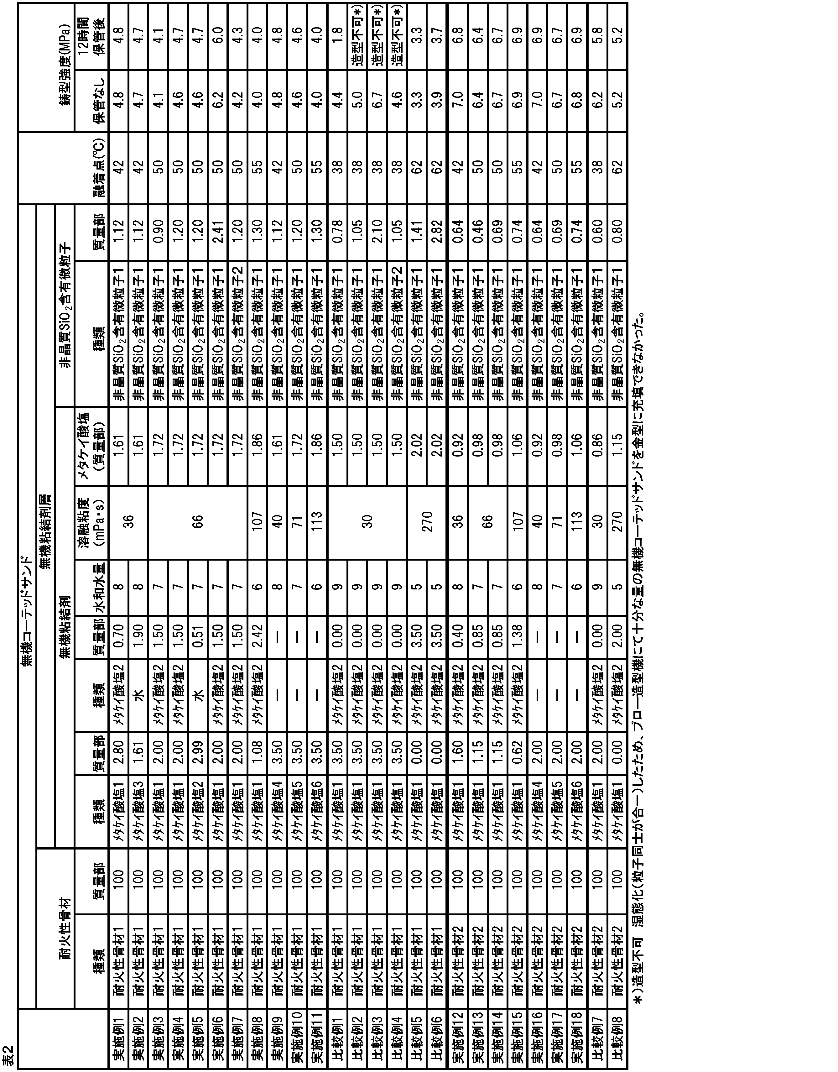
Claims (10)
- 耐火性骨材と、前記耐火性骨材の表面を覆う無機粘結剤層と、を有する乾態の無機コーテッドサンドであって、
前記無機粘結剤層がメタケイ酸塩水和物と非晶質SiO2含有微粒子を含有し、当該無機粘結剤層を構成する無機粘結剤の80℃における溶融粘度が32mPa・s以上、150mPa・s以下である、無機コーテッドサンド。 - 耐火性骨材と、前記耐火性骨材の表面を覆う無機粘結剤層と、を有する乾態の無機コーテッドサンドであって、
前記無機粘結剤層がメタケイ酸塩水和物および非晶質SiO2含有微粒子を含有し、当該メタケイ酸塩水和物の水和水量が6以上、8以下である、無機コーテッドサンド。 - 耐火性骨材と、前記耐火性骨材の表面を覆う無機粘結剤層と、を有する乾態の無機コーテッドサンドであって、
前記無機粘結剤層がメタケイ酸塩水和物および非晶質SiO2含有微粒子を含有し、
JACT試験法 C-1 融着点試験法に準じた融着点が40℃以上、60℃以下である、無機コーテッドサンド。 - 請求項1乃至3のいずれか一項に記載の無機コーテッドサンドであって、
前記無機コーテッドサンドに含まれる前記無機粘結剤層が、前記耐火性骨材100質量部に対して、0.2質量部以上、15質量部以下である、無機コーテッドサンド。 - 請求項1乃至4のいずれか一項に記載の無機コーテッドサンドであって、
前記非晶質SiO2含有微粒子の含有量が、前記耐火性骨材100質量部に対して、0.1質量部以上、10質量部以下である、無機コーテッドサンド。 - 請求項1乃至5のいずれか一項に記載の無機コーテッドサンドを用いた鋳造用鋳型。
- 請求項1乃至5のいずれか一項に記載の無機コーテッドサンドを含有する、無機コーテッドサンド組成物。
- 請求項7に記載の無機コーテッドサンド組成物を用いた鋳造用鋳型。
- 請求項1乃至5のいずれか一項に記載の無機コーテッドサンドの製造方法であって、
前記耐火性骨材と、メタケイ酸塩9水和物と、メタケイ酸塩5水和物と、を混合して混合物を得る工程(1)と、
該混合物を冷却する工程(2)と、
を含み、
前記工程(1)は、前記メタケイ酸塩9水和物および前記メタケイ酸塩5水和物からなる混合体の溶融点以上の温度で混合し、
前記工程(2)は、前記メタケイ酸塩9水和物および前記メタケイ酸塩5水和物からなる混合体の溶融点未満の温度以下となるように冷却する、無機コーテッドサンドの製造方法。 - 請求項1乃至5のいずれか一項に記載の無機コーテッドサンドの製造方法であって、
前記耐火性骨材と、水ガラス、苛性アルカリ、および水を含む溶液と、を混合して、メタケイ酸塩水和物を含む混合物を得る工程(3)を含む、無機コーテッドサンドの製造方法。
Priority Applications (3)
| Application Number | Priority Date | Filing Date | Title |
|---|---|---|---|
| KR1020257039302A KR20260003092A (ko) | 2023-06-08 | 2024-06-06 | 무기 코티드 샌드 및 그 제조 방법, 무기 코티드 샌드 조성물, 그리고 주조용 주형 |
| CN202480037978.7A CN121263260A (zh) | 2023-06-08 | 2024-06-06 | 无机覆膜砂及其制造方法、无机覆膜砂组合物以及铸造用铸型 |
| MX2025013953A MX2025013953A (es) | 2023-06-08 | 2025-11-21 | Arena recubierta inorganica y metodo de fabricacion de la misma, composicion de arena recubierta inorganica y molde de vaciado |
Applications Claiming Priority (4)
| Application Number | Priority Date | Filing Date | Title |
|---|---|---|---|
| JP2023094824 | 2023-06-08 | ||
| JP2023-094824 | 2023-06-08 | ||
| JP2024-092070 | 2024-06-06 | ||
| JP2024092070A JP2024177122A (ja) | 2023-06-08 | 2024-06-06 | 無機コーテッドサンドおよびその製造方法、無機コーテッドサンド組成物、ならびに鋳造用鋳型 |
Publications (1)
| Publication Number | Publication Date |
|---|---|
| WO2024253166A1 true WO2024253166A1 (ja) | 2024-12-12 |
Family
ID=93796085
Family Applications (1)
| Application Number | Title | Priority Date | Filing Date |
|---|---|---|---|
| PCT/JP2024/020736 Ceased WO2024253166A1 (ja) | 2023-06-08 | 2024-06-06 | 無機コーテッドサンドおよびその製造方法、無機コーテッドサンド組成物、ならびに鋳造用鋳型 |
Country Status (3)
| Country | Link |
|---|---|
| KR (1) | KR20260003092A (ja) |
| MX (1) | MX2025013953A (ja) |
| WO (1) | WO2024253166A1 (ja) |
Citations (7)
| Publication number | Priority date | Publication date | Assignee | Title |
|---|---|---|---|---|
| JPS4853929A (ja) * | 1971-11-10 | 1973-07-28 | ||
| JPS5020543B1 (ja) * | 1969-11-07 | 1975-07-16 | ||
| JPS5026498B1 (ja) * | 1969-05-27 | 1975-09-01 | ||
| JPS5325803B2 (ja) * | 1972-03-03 | 1978-07-28 | ||
| JP2000176612A (ja) * | 1998-12-14 | 2000-06-27 | Mintekku Japan Kk | タンデイッシュ用表面被覆材 |
| WO2020012934A1 (ja) * | 2018-07-09 | 2020-01-16 | 花王株式会社 | 無機コーテッドサンド |
| JP2021194647A (ja) * | 2020-06-09 | 2021-12-27 | 富士化学株式会社 | 鋳物用砂型製造用組成物、及び鋳物用砂型の製造方法 |
Family Cites Families (2)
| Publication number | Priority date | Publication date | Assignee | Title |
|---|---|---|---|---|
| JPS5325803A (en) | 1976-08-24 | 1978-03-10 | Toshiba Corp | Coil dismantling method in core of rotary machine |
| JP7055753B2 (ja) | 2016-11-22 | 2022-04-18 | 旭有機材株式会社 | コーテッドサンド及びその製造方法並びにこれを用いた鋳型の製造方法 |
-
2024
- 2024-06-06 KR KR1020257039302A patent/KR20260003092A/ko active Pending
- 2024-06-06 WO PCT/JP2024/020736 patent/WO2024253166A1/ja not_active Ceased
-
2025
- 2025-11-21 MX MX2025013953A patent/MX2025013953A/es unknown
Patent Citations (7)
| Publication number | Priority date | Publication date | Assignee | Title |
|---|---|---|---|---|
| JPS5026498B1 (ja) * | 1969-05-27 | 1975-09-01 | ||
| JPS5020543B1 (ja) * | 1969-11-07 | 1975-07-16 | ||
| JPS4853929A (ja) * | 1971-11-10 | 1973-07-28 | ||
| JPS5325803B2 (ja) * | 1972-03-03 | 1978-07-28 | ||
| JP2000176612A (ja) * | 1998-12-14 | 2000-06-27 | Mintekku Japan Kk | タンデイッシュ用表面被覆材 |
| WO2020012934A1 (ja) * | 2018-07-09 | 2020-01-16 | 花王株式会社 | 無機コーテッドサンド |
| JP2021194647A (ja) * | 2020-06-09 | 2021-12-27 | 富士化学株式会社 | 鋳物用砂型製造用組成物、及び鋳物用砂型の製造方法 |
Also Published As
| Publication number | Publication date |
|---|---|
| KR20260003092A (ko) | 2026-01-06 |
| MX2025013953A (es) | 2026-01-07 |
Similar Documents
| Publication | Publication Date | Title |
|---|---|---|
| JP7721615B2 (ja) | 無機コーテッドサンド | |
| CN112703071A (zh) | 制备用于制造铸造模具和型芯的粒状耐火组合物的方法、相应的用途以及用于热处理的再生混合物 | |
| JP6832469B1 (ja) | 無機コーテッドサンド | |
| JP6865715B2 (ja) | 耐火性骨材 | |
| JP2024018294A (ja) | 無機コーテッドサンドおよびその製造方法、ならびに無機コーテッドサンドの保存安定性向上方法 | |
| WO2024253166A1 (ja) | 無機コーテッドサンドおよびその製造方法、無機コーテッドサンド組成物、ならびに鋳造用鋳型 | |
| JP2024177122A (ja) | 無機コーテッドサンドおよびその製造方法、無機コーテッドサンド組成物、ならびに鋳造用鋳型 | |
| CN113825575A (zh) | 包括微粒状合成非晶二氧化硅作为用于模制材料混合物的添加剂的粒子材料的应用、相应的方法、混合物和试剂盒 | |
| JP2025034473A (ja) | 無機コーテッドサンドの製造方法および鋳造用鋳型の製造方法 | |
| JP2024018288A (ja) | 無機コーテッドサンドおよびその製造方法、ならびに無機コーテッドサンドの保存安定性向上方法 | |
| JP7853102B2 (ja) | 無機コーテッドサンド | |
| WO2022244280A1 (ja) | 無機コーテッドサンド | |
| JP2025048800A (ja) | 乾態の無機コーテッドサンド、乾態の無機コーテッドサンドの製造方法および鋳型の製造方法 | |
| WO2025063245A1 (ja) | 乾態の無機コーテッドサンド、乾態の無機コーテッドサンドの製造方法および鋳型の製造方法 | |
| JP2025033496A (ja) | 無機コーテッドサンドの製造方法、および鋳型の製造方法 | |
| JP7700317B2 (ja) | 無機コーテッドサンドおよびその製造方法、鋳造用鋳型、ならびに無機コーテッドサンドの保存安定性の向上方法 | |
| WO2026028892A1 (ja) | コーテッドサンドの製造方法 | |
| JP7490626B2 (ja) | 無機コーテッドサンド | |
| JP2025104451A (ja) | 無機コーテッドサンドおよび無機コーテッドサンドの製造方法 | |
| JP2026025946A (ja) | コーテッドサンドの製造方法 | |
| JP2025098412A (ja) | 無機コーテッドサンドおよび無機コーテッドサンドの製造方法 | |
| KR20260057126A (ko) | 건조 형태의 무기 코티드 샌드, 건조 형태의 무기 코티드 샌드의 제조 방법 및 주형의 제조 방법 | |
| JP7671898B2 (ja) | 鋳型用鋳物砂およびその製造方法、鋳造用鋳型、ならびに鋳型用鋳物砂の保存安定性の向上方法 | |
| CN105073298A (zh) | 制造用于铸造目的的芯砂和/或型砂的方法 | |
| WO2024237147A1 (ja) | 無機コーテッドサンドおよびその製造方法、鋳造用鋳型、ならびに無機コーテッドサンドの保存安定性の向上方法 |
Legal Events
| Date | Code | Title | Description |
|---|---|---|---|
| 121 | Ep: the epo has been informed by wipo that ep was designated in this application |
Ref document number: 24819394 Country of ref document: EP Kind code of ref document: A1 |
|
| WWE | Wipo information: entry into national phase |
Ref document number: MX/A/2025/013953 Country of ref document: MX |
|
| ENP | Entry into the national phase |
Ref document number: 1020257039302 Country of ref document: KR Free format text: ST27 STATUS EVENT CODE: A-0-1-A10-A15-NAP-PA0105 (AS PROVIDED BY THE NATIONAL OFFICE) |
|
| WWE | Wipo information: entry into national phase |
Ref document number: 202517124762 Country of ref document: IN |
|
| WWP | Wipo information: published in national office |
Ref document number: 202517124762 Country of ref document: IN |
|
| WWP | Wipo information: published in national office |
Ref document number: MX/A/2025/013953 Country of ref document: MX |
|
| NENP | Non-entry into the national phase |
Ref country code: DE |